Vintage Aprilia 2007 - Altervista
85
Vintage Aprilia 2007 Vintage Aprilia 2007
Transcript of Vintage Aprilia 2007 - Altervista
Vintage Aprilia 2007
Vintage Aprilia 2007
125A GGIQ RNAMENT O ERRATA COR RIGEIro
DESCRIZIONE CORRETTAOESCRIZ IONE PA£C EDENTEPAG.
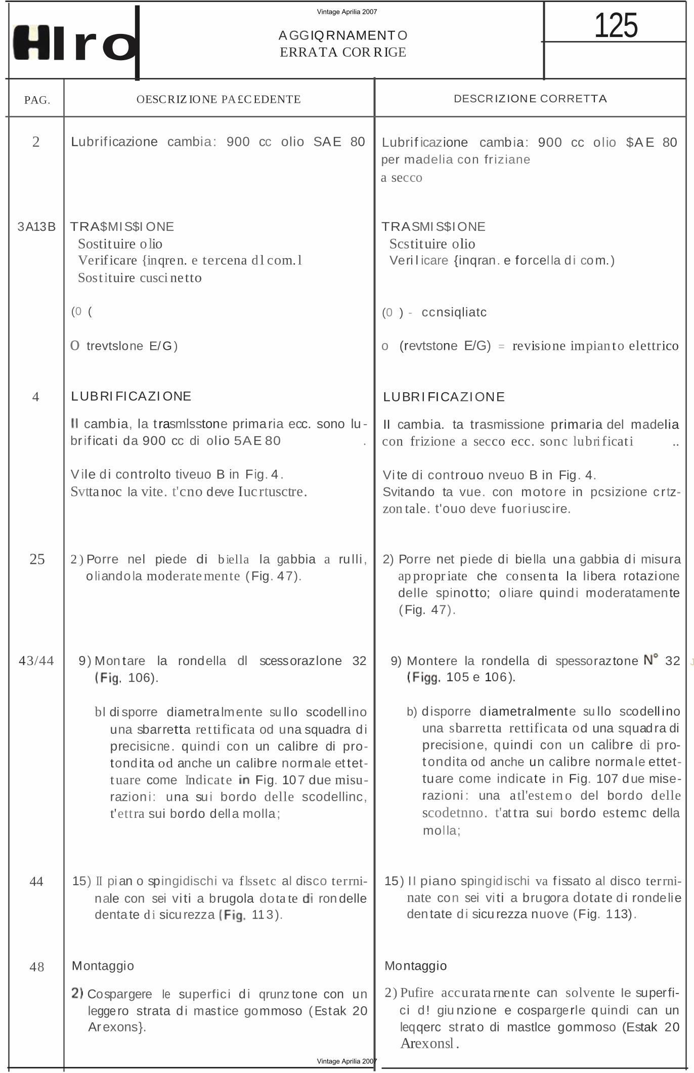
2 Lubrif icazione cambia: 900 cc olio SAE 80
3A13B TRA$MIS$I ONE Sostituire olio Verif icare {inqren. e tercena d l com. l Sost ituire cusci netto
(0 (
o trevtslone E/ G )
4 LUBRI FICAZI ONE
cambia, la t rasmlsstone primaria ecc. sono lu -br if icat i da 900 cc di ol io 5AE 80 .
V ile d i controlto tiveuo B in Fig. 4 . Svttanoc la vite. t'cno deve Iuc rtusctre.
25 2 ) Porre nel piede di b iella la gabbia o liando la moderate mente (Fig. 47).
a ru lli ,
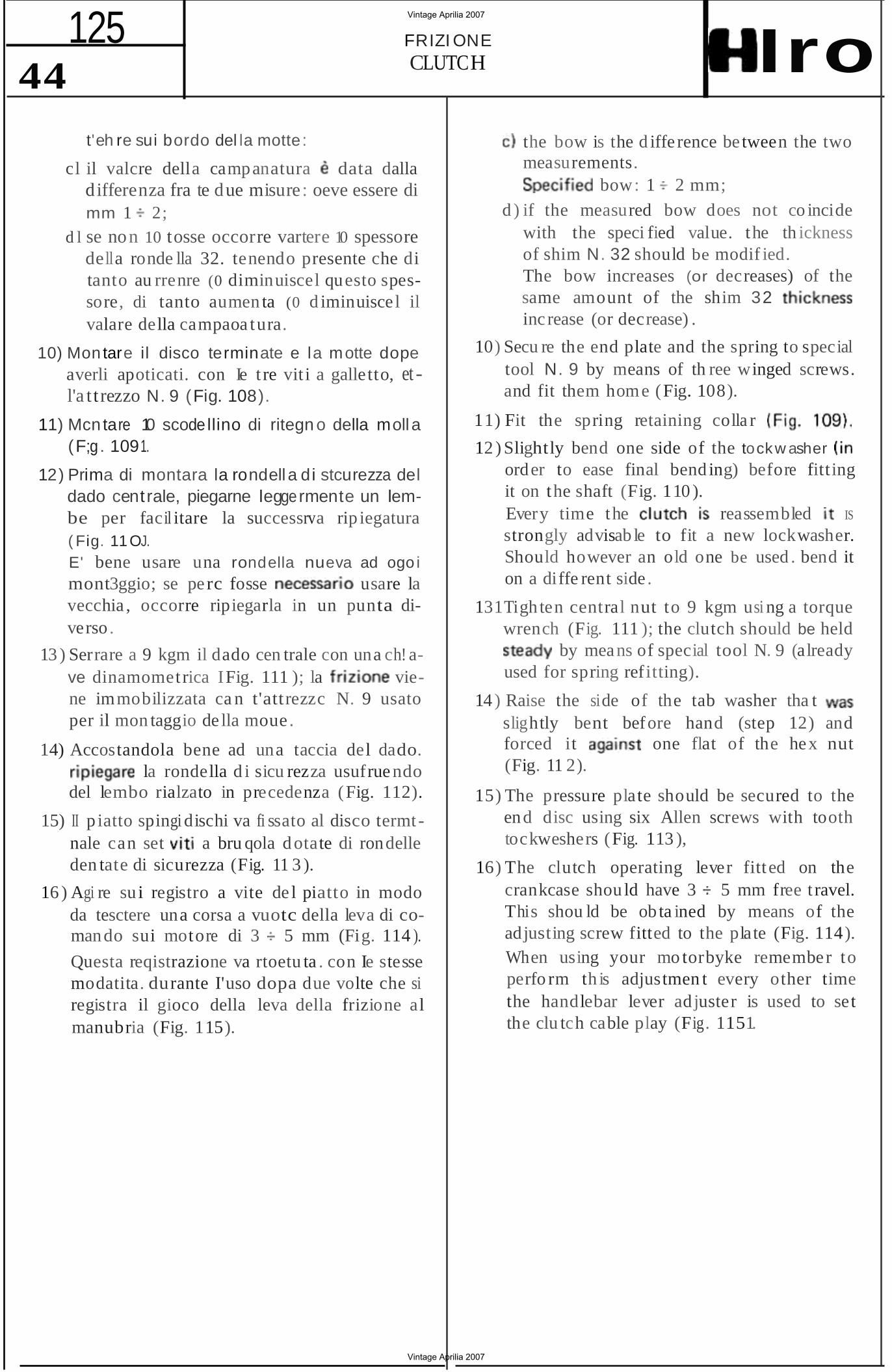
43/44 9) Mon tare la 106).
rondella dl scessorazlone 32
b l di sporre diametra lmente su llo scodell ino una sbarretta re t tificata od una squadra d i precisicne. quind i con un calibre di protond ita od anche un calibre normaIe et tett uare come Indicate Fig. 107 due misurazion i: una su i bordo delle scodellinc, t'ettra sui bordo della molla ;
44 15) II pian o spingidischi va flssetc al disco terrninale con sei vi ti a brugola dota te ron delle denta te d i sicu rezza 11 3 ).
Lubrif icazione cambia: 900 cc olio $A E 80 per madelia con fr iziane
a secco
TRASMI S$IONE Scstituire olio Veri l icare {inqran. e forcel la d i com.)
(0 ) - ccnsiqliatc
o (revtstone E/G) = revisione impian to elettrico
LUBRI FICAZIONE
II cambia. ta trasmissione primaria del madelia con frizione a secco ecc. sonc lubri ficat i ..
Vi te di controuo nveuo B in Fig. 4.Svitando ta vue. con motore in pcsizione c r tzzon tale. t'ouo deve f uoriusc ire.
2) Porre net piede di biella una gabbia d i misura ap propr iate che consen ta la libera rotazione delle spinotto; o liare quind i moderatamente (Fig. 47).
9) Montere la rondella di spessoraztone 32 J
105 e 106).
b) d isporre d iametralmente su llo scodell ino una sbarre tta rettifica ta od una squadra di precisione, quindi con un calibre di protondita od anche un calibre normale ettettuare come indicate in Fig. 107 due miserazioni : una atl'estem o del bordo delle scodetnno. t'at t ra sui bordo estemc della mol la;
15) I I piano spingid ischi va f issato al disco terrninate con sei vi ti a brugora dotate d i rondelie den tate d i sicu rezza nuove (Fig. 113).
Montaggio
Cospargere Ie superfic i d i qrunz tone con un leggero strata d i mast ice gommoso ( Estak 20 Arexons}.
Montaggio
2) Pufire accurata rnente can solvente Ie superfici d ! giu nzione e cospargerle quindi can un leqqerc st rat o di mastlce gommoso (Estak 20 Arexonsl .
48
Vintage Aprilia 2007
Vintage Aprilia 2007
-------
125 AGGIORNAMENTOERRATA CORRIGE IIlro
PAG. DESCRlZ10 NE PRECEDENTE DESCRI ZION E CORR ET TA
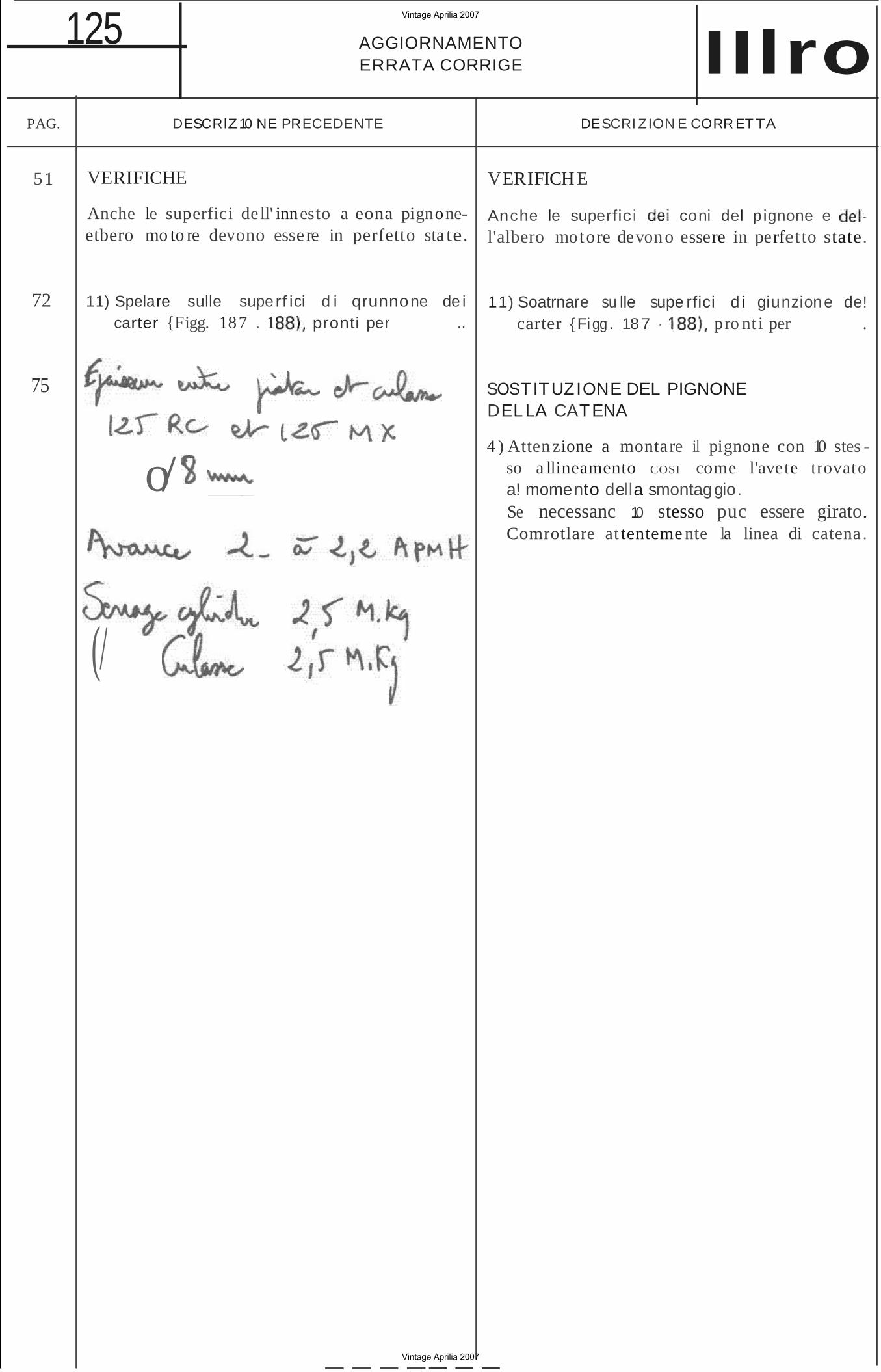
VERIFICHE 51
Anche le superfici de ll' innesto a eona pignoneetbero mo to re devono essere in perfetto sta te.
72 11) Spelare sulle superf ici d i qrunnone de i carter {Figg. 187 . 1 pronti per ..
75
o/
(/
VERIFICHE
Anche le superfici coni del p ignone e l'albero motore devon o essere in perfetto state.
11) Soatrnare su lle supe rfici d i giunzione de! carter { Figg . 18 7 · pro nt i per .
SOSTITUZIONE DEL PIGNONE DEL LA CATENA
4 ) Atten zione a montare il pignone con 10 stes so a llineamento COSI come l'avete trovato a! momento della smontaggio. Se necessanc 10 stesso puc essere girato. Comrotlare at tenteme nte la linea di catena .
Vintage Aprilia 2007
Vintage Aprilia 2007
2
125UP-DATING ERRATA CORRIGE IIlro
PAGE PREVIOUS DESCRIPT ION
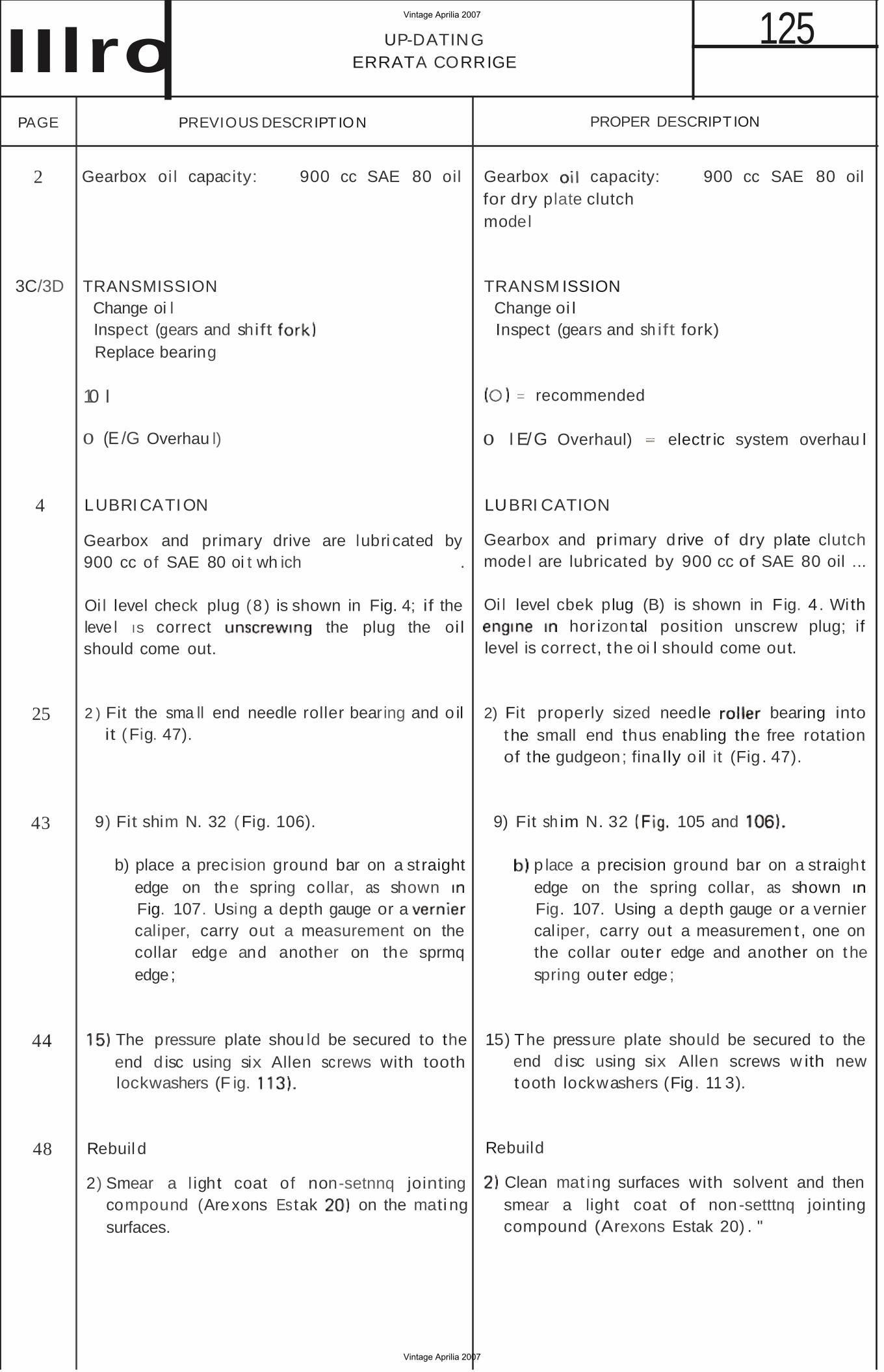
Gearbox oi l capacity: 900 cc SAE 80 oil
3C/3D
4
25
43
44
48
TRANSMISSION Change oi l Inspect (gears and shift Replace bearing
10 I
o (E /G Overhau l)
LUBRI CATION
Gearbox and primary drive 900 cc of SAE 80 oi t wh ich
are lubri cated by .
Oi l level check plug (8 ) is shown in Fig. 4; if the leve l IS correct the plug the oi l should come out.
2 ) Fit the sma ll end needle roller bearing and o il it (Fig. 47).
9) Fit shim N. 32 (Fig. 106).
b) place a prec ision ground bar on a st raight edge on the spring collar, as shown Fig. 107. Using a depth gauge or a caliper, carry out a measurement on the collar edge and another on the sprmq edge;
The pressure plate shou ld be secured to the end d isc using six Allen screws with tooth lockwashers (F ig.
Rebuil d
2) Smear a l ight coat of non-setnnq jointing compound (Arexons Estak on the mati ng surfaces.
PROPER DESCRIPT ION
Gearbox capacity: 900 cc SAE 80 oil for dry plate clutch model
TRANSM ISSION Change oi l Inspect (gears and sh ift fork)
= recommended
o I E/G Overhaul) electr ic system overhau l
LUBRI CATION
Gearbox and primary d rive of dry plate clutch mode l are lubricated by 900 cc of SAE 80 oil ...
Oi l level cbek plug (B) is shown in Fig. 4 . With hor izon tal position unscrew plug; if
level is correct, t he oi l should come out.
2) Fit properly sized needle bearing into the small end thus enabling the free rotation of the gudgeon; fina lly o il it (Fig . 47).
9) Fit sh im N. 32 105 and
p lace a precision ground bar on a st raight edge on the spring collar, as shown Fig. 107. Using a depth gauge or a vernier cal iper, carry out a measuremen t , one on the collar outer edge and another on the spring outer edge;
15) The pressure plate should be secured to the end d isc using six Allen screws w ith new t ooth lockwashers (Fig. 11 3).
Rebuild
Clean mat ing surfaces with solvent and then smear a light coat of non-setttnq jointing compound (Arexons Estak 20) . "
Vintage Aprilia 2007
Vintage Aprilia 2007
125 UP-DATINGERRATA CORR IGE Hlro
PAGE PRE VIO US DESCRI PTIO N PROPER DESCR IPTION
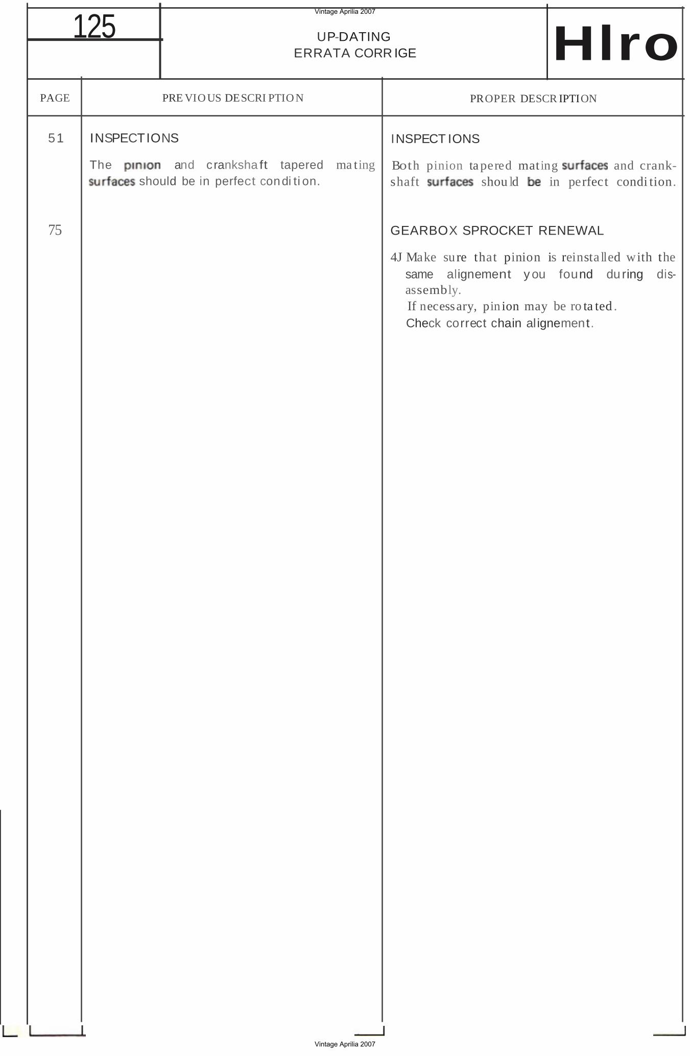
51 INSPECTIONS INSPECT IONS
The and cranksha ft tapered ma ting Both pinion ta pered mating and crankshould be in perfect condi ti on. shaft shou ld in perfect condi tion.
75 GEARBOX SPROCKET RENEWAL
4J Make sure that pinion is reinsta lled with the same alignement y ou found du ring disassembly. If necessary, pin ion may be ro ta ted . Check correct chain al ignement.
L
Vintage Aprilia 2007
Vintage Aprilia 2007
125INDI CEINDEXHlro
paqtna page
Caran ens tic be tecnicbe 1 Technical featu res 1 Sche ma ingomb ro 2A Overal l d iagram 2A Attrezzi speci a l! 3 Specia l t ools 3
Schema d i manutenzione - usa agonistico 3A Maintena nce schedule - 3C Schema d i manu tenz ion e - usa stradaIe 3B Maintenance schedule . tour ism 3D Smontaggio e reVISlo ne . lubri f ica zione 4 Disassembli ng and overhautinq . Lubrication. 4 Carburatore 7 Carbu retor 7 lmpianto ele tt rico 11 Elect r ica l system 11 Testa . ci lindro - oistone 19 Cyl inder bead - cy l inder ' p iston 19 Albero motore 30 Crankshaft 30 Frizione 37 Clutch 37 Trasmissio ne prtmar!a 4 7 d r ive 4 7 Disposi t ivo di avviamen to 55 Ki ckstarte r mechanism 55 Co mando del camb ia 6 1 Gea rshi ft mechanism 61 Cambi a 62 Gearbox 62
Vintage Aprilia 2007
Vintage Aprilia 2007
125 Vintage Aprilia 2007
Vintage Aprilia 2007
125CA RATTERISTICHE TECNICHEHlro TECHN ICAL FEATURES 1
e corsa 54)(54 mm
123,6 cc
Volume camera d i : 9 ·9.2ee SCOPP IO (esclcso tnenc candela)
Cil indro in al lumi nio con cann a ero
mata lr icromabi le)
benz ina con o lio mctcee tse o l io normale in
mercia)
benzme con di
OIL 2T5 Carburato re to PHBE 32 as · Gen a max
· Getto m in . aueners! ailel· Sp illo
· vervora case · Polverizza tore
· Gen o starter
Carbura lore cross Dell'Orto PH BE 36 BS
.· Geno max
· Gen o min .
· Spillo
· vatcota · Pcivenzzatore
· Gen a Slart er
Distnbozic ne rego1ar.
aitenerst aile
regol azio n i
del la Case
· Scarico 198°
· 1340 136"
·
Distribuzione cross
· Sea-icc 20 2° 2040
· Trevesi 1340 .;. 1360
· Aspirazione 190° + 19 2°
Cande la Magneti Ma re lli CWP 10 l (file tto
{fa gli ele trrodi : 0 .5 .;. 0.6 mm
Anticipo acceestone 2 .2 mm p rima PMS
Volano Mato p lat mod. con generator!! oorenea 6V .
' OW vctenc cross Motopla t mod. 9600 193·1 0
9 600993 ·1
Biella in ecct e rc stampatc con ru lli
ingabb iati alia e a! p iede
Albef n mo tore in tee mcntatc su cu
sctoen t a stere
Friziooe a secco a d ischi. muhi pli
con a diaf ramma
p . co n in secrete a
den t i
r apportc 3.588 61/1 7
rimaria
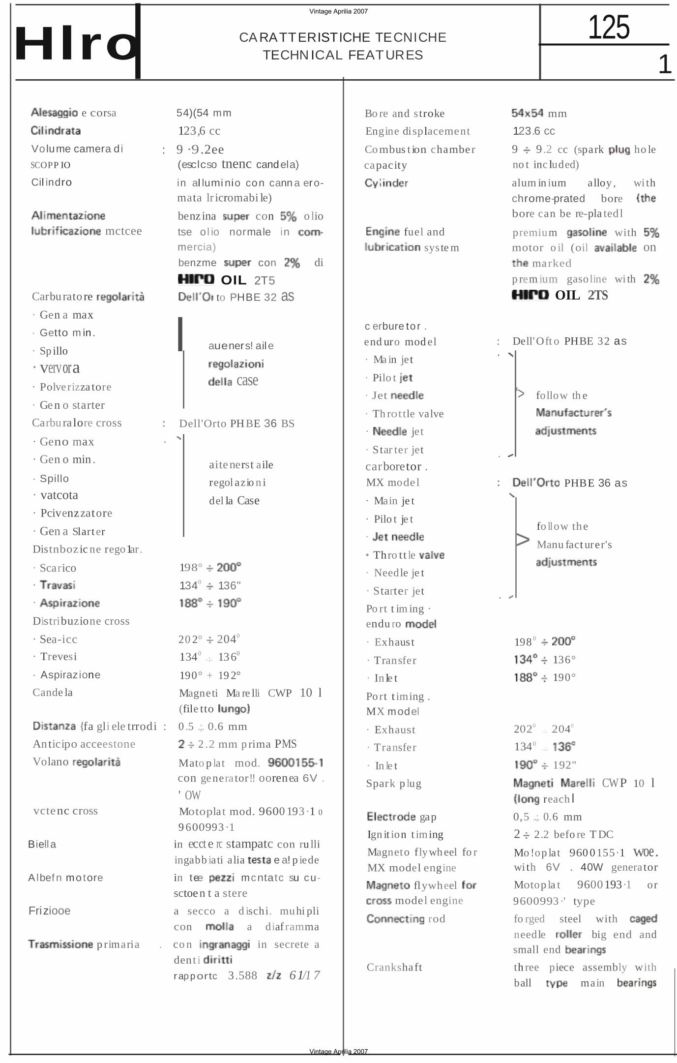
Bo re and stroke
Engine displacement
Co mbus t ion chamber
capacity
fuel and
sys te m
c erbure to r .
end uro mod el
· Ma in jet
· Pilo t
· Jet
· Th rottle valve
· jet
· S tar ter jet
mm
123.6 cc
9 9.2 cc (spark ho le no t inc luded)
alum in ium alloy , wi th
chrome-prated bore bore can be re-pla tedl
premium with motor o il (oil on
marked
p rem ium gasoline wi th
OIL 2TS
: Dell'Oft o PHBE 32 as ·
'> follow th e
· carboretor . MX model PHBE 36 as
· Main je t
· Pilo t je t
·
• Thro tt le
· Needle je t
fo llow the
> Manu fact urer's
· Starter jet · Po rt t im ing · endu ro
· Exhaus t
· Transfer
· In le t
Po rt t iming . MX model
· Exhaust
· Transfer
· In le t
Spark p lug
gap
Ign it ion t iming
Magneto flywheel fo r
MX model engine
flywheel model engine
rod
Crankshaft
198 0
136°
190°
2020
1340
..;.
..;.
2040
192"
CWP 10 l reach I
0,5 ..;. 0.6 mm
2 2.2 befo re T DC
Mo!op lat 960 0155·1 woe. wi th 6V . 40W generator
Motop la t 9600193·1 or
9600993 ·' type
fo rged steel with
needle big end and small end
th ree piece assembly with
ball main
Vintage Aprilia 2007
Vintage Aprilia 2007
2 125 CARATTER ISTlCHE TECNICHE
TECHNICAL FEATURES
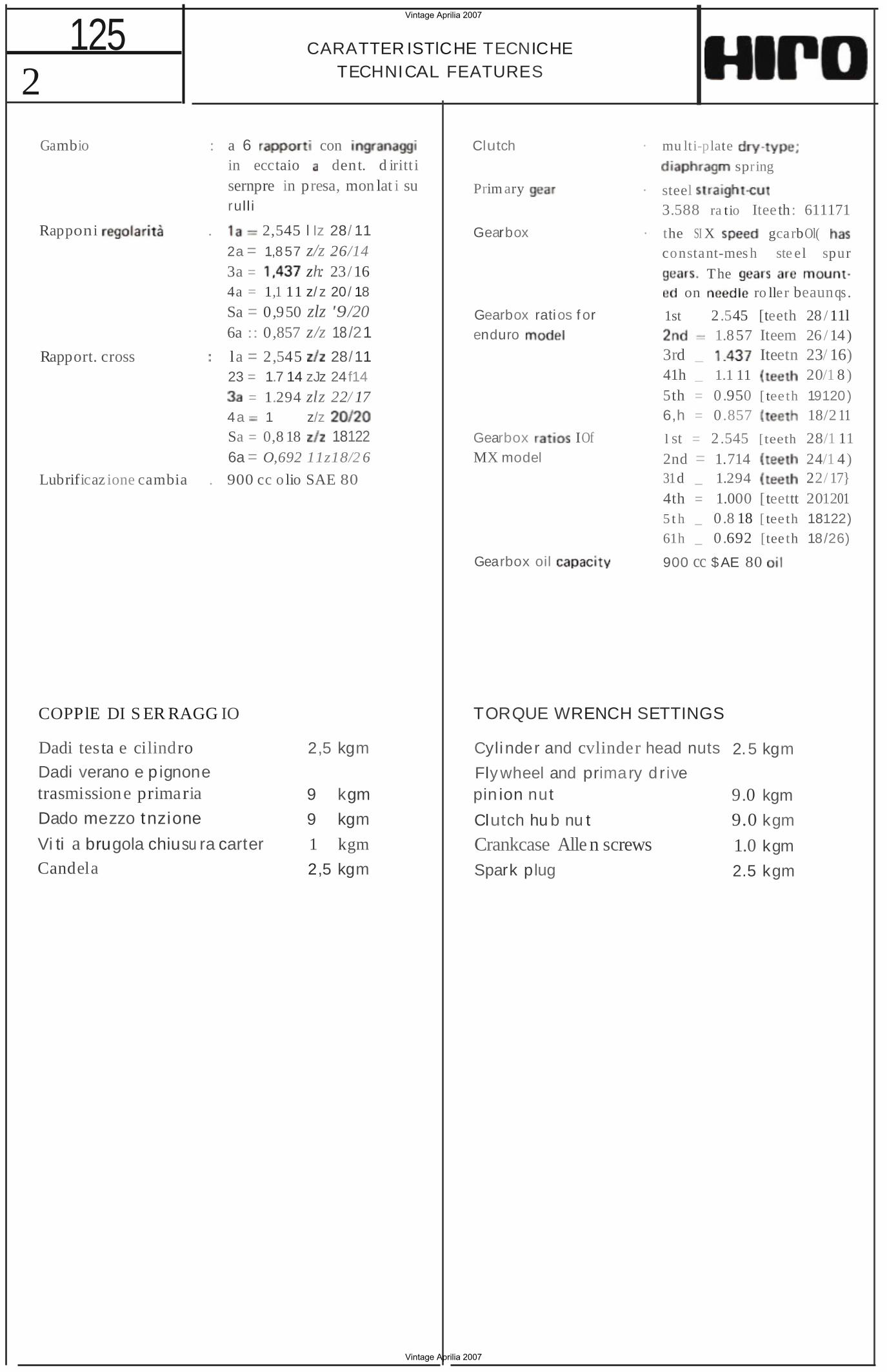
Gambio : a 6 in ecctaio
con dent. d iritt i
sernpre rull i
in presa, mon lat i su
Rapponi . 2,545 l Iz 28/ 11 2a = 1,8 57 z/z 26/14 3a = zh: 23/ 16 4a = 1,1 11 z/ z 20/ 18
Sa = 0,950 zlz '9/20 6a :: 0,857 z/z 18 /21
Rapport. cross la = 23 =
2,545 28/11 1.7 14 zJz 24f14
= 1.294 zlz 22/ 17 4a 1 z/z Sa = 0,8 18 18122 6a = O,692 11z18/2 6
Lubrificaz ione cambia . 900 cc o lio SAE 80
COPPlE DI S ER RAGG IO
Dadi testa e cilindro 2,5 kgm
Dadi verano e p ignone trasmissione primaria 9 kgm
Dado mezzo tnzione 9 kgm
Vi ti a brugola chiusu ra carter 1 kgm
Candela 2,5 kgm
Clutch · mu lti-plate
spring
Prim ary · steel 3.588 ra tio Itee th: 611171
Gearbox · the SI X gcarbOl( constant-mes h ste el spur
The on ro ller beaunqs.
Gearbox ratios f or 1st 2 .545 [teeth 28 / 11l enduro 1.857 Iteem 26 / 14)
3rd _ Iteetn 23/ 16) 41h _ 1.1 11 20/1 8 ) 5th = 0.950 [ tee th 19120) 6,h = 0.857 18/2 11
Gearbox IOf l st = 2.545 [teeth 28/1 11 MX model 2nd = 1.714 24/1 4)
31d _ 1.294 22/ 17} 4th = 1.000 [teettt 201201 5 t h _ 0 .8 18 [ tee th 18122) 61h _ 0 .692 [tee th 18/26)
Gearbox oil 900 cc $AE 80
TORQUE WRENCH SETTINGS
Cylinder and cvlinder head nuts 2.5 kgm
Fly wheel and primary d rive pin ion nut 9.0 kgm
Clutch hu b nu t 9.0 kgm
Crankcase Alle n screws 1.0 kgm
Spark plug 2.5 kgm
Vintage Aprilia 2007
Vintage Aprilia 2007
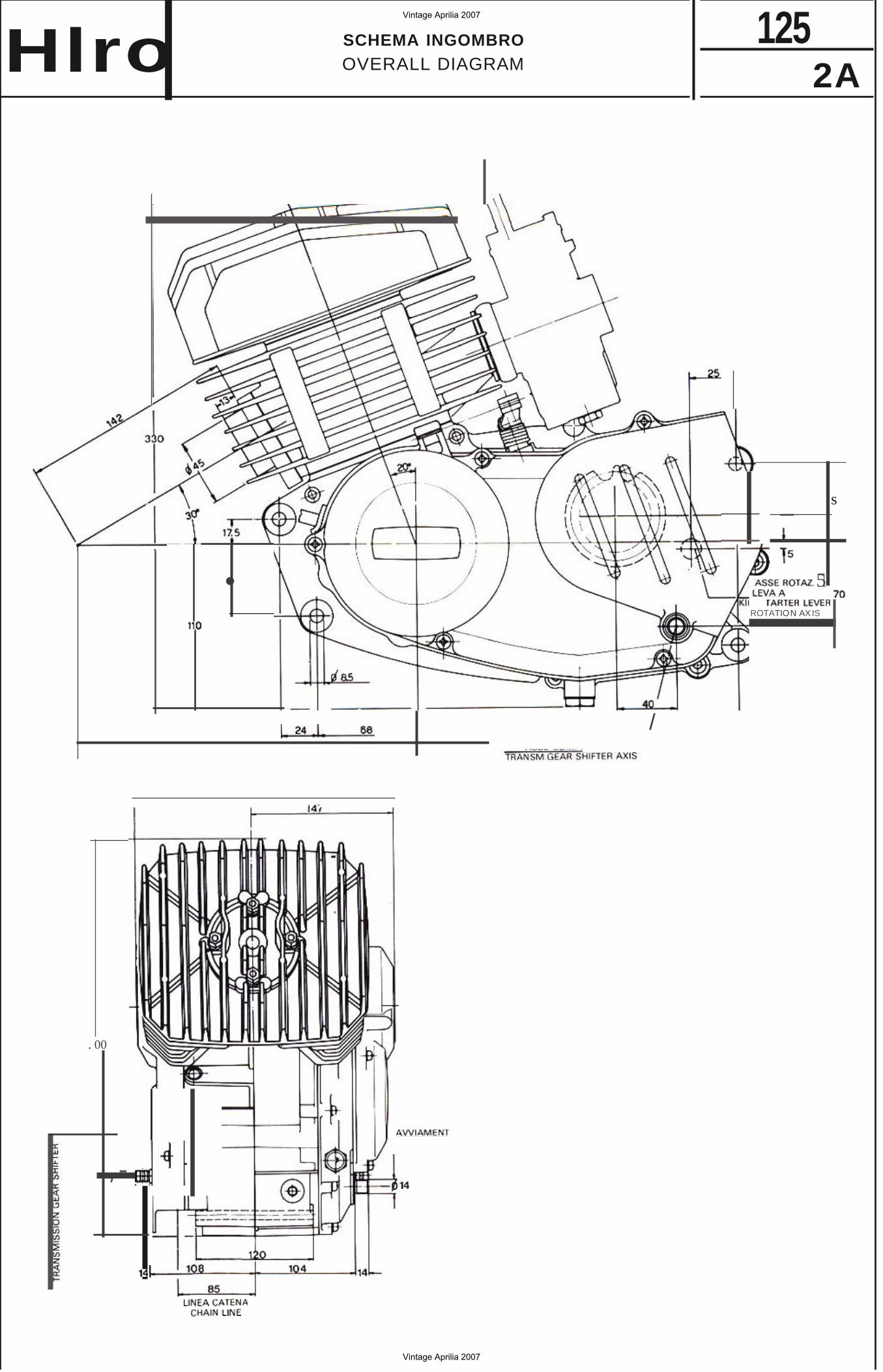
125SCHEMA INGOMBROOVERALL DIAGRAMHlro 2A
•
s
51'
ROTATION AXIS
/
. 00
,
Vintage Aprilia 2007
Vintage Aprilia 2007
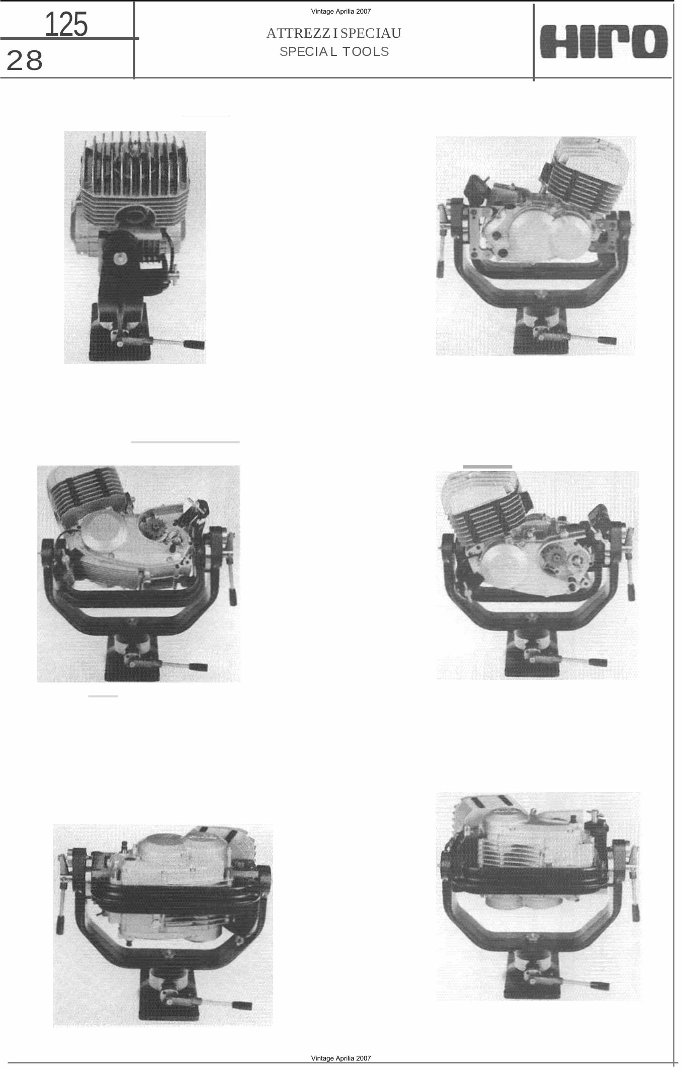
125 28
ATTREZZ I SPECIAU SPECIA L TOOLS
Vintage Aprilia 2007
Vintage Aprilia 2007
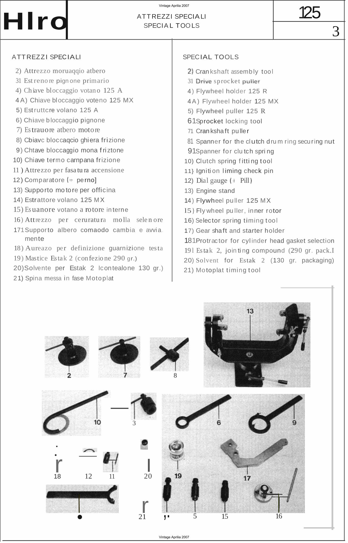
3 125 ATT REZZI SPECIA LI
SPECIA L TOO LSHlro ATTREZZ I SPECIALI
2) Attrezzo moruaqqio atbero
31 Est reno re pign one primario
4) Ch iave bloccaggio votan o 125 A4 A) Chiave bloccaggio voteno 125 MX
5) Est ruttcre volano 125 A
6) Chiave b loccaggio pignone
7) Es trauore atbero motore 8) Cbiavc bloccaqcio ghiera fr izione
9) Chtave bloccaggio mona f ri ztone
10) Chiave terrno carnpana fr izione
11 ) Attrezzo per fasa tu ra accensione
12 ) Comparatore perno]
13) Supporto mo to re per offic ina
14) Estrattore volano 125 M X
15) Es uanore votano a rotore in terne
16) Attrezzo pe r ceruratu ra mo lla sele n ore
171Suppor to albero comaodo cambia e avvia. mente
18) Aureazo per definizione guarn izione tes ta
19) Mastice Estak 2 (confezio ne 290 gr.)
20)Solvente per Estak 2 Icon tealone 130 gr.)
21) Spina messa in fase Motoplat
SPECIAL TOOLS
Cran kshaft assemb ly too l
31 sp rocket
4 ) Flywheel holder 125 R
4 A ) Flywheel holder 125 MX
5) Flywheel puller 125 R
61Sprocket locking tool
71 Cran ksha ft pu lle r
81 Spanner for the clutch dru m ring securing nut
91Spanner fo r clu tch spri ng
10) Clutch spring f itti ng t ool
11} Igni ti on l iming check pin
12) Dial gauge Pill
13) Engine stand
14) Flywheel pu ller 125 M X
l5} Fly wheel pu ller , inner rotor
16) Selec tor spring t iming t oo l
17) Gear sha ft and starter holder
181Protrac tor for cyl inder head gasket selection
19 l Es tak 2, join ti ng compound (290 gr. pack.I
20) Solvent for Estak 2 (130 gr. packaging)
21) Motoplat t iming t ool
8
3
•
•
r I 18 12 11 20 19 17
r 5 15 1621 ,.•
Vintage Aprilia 2007
Vintage Aprilia 2007
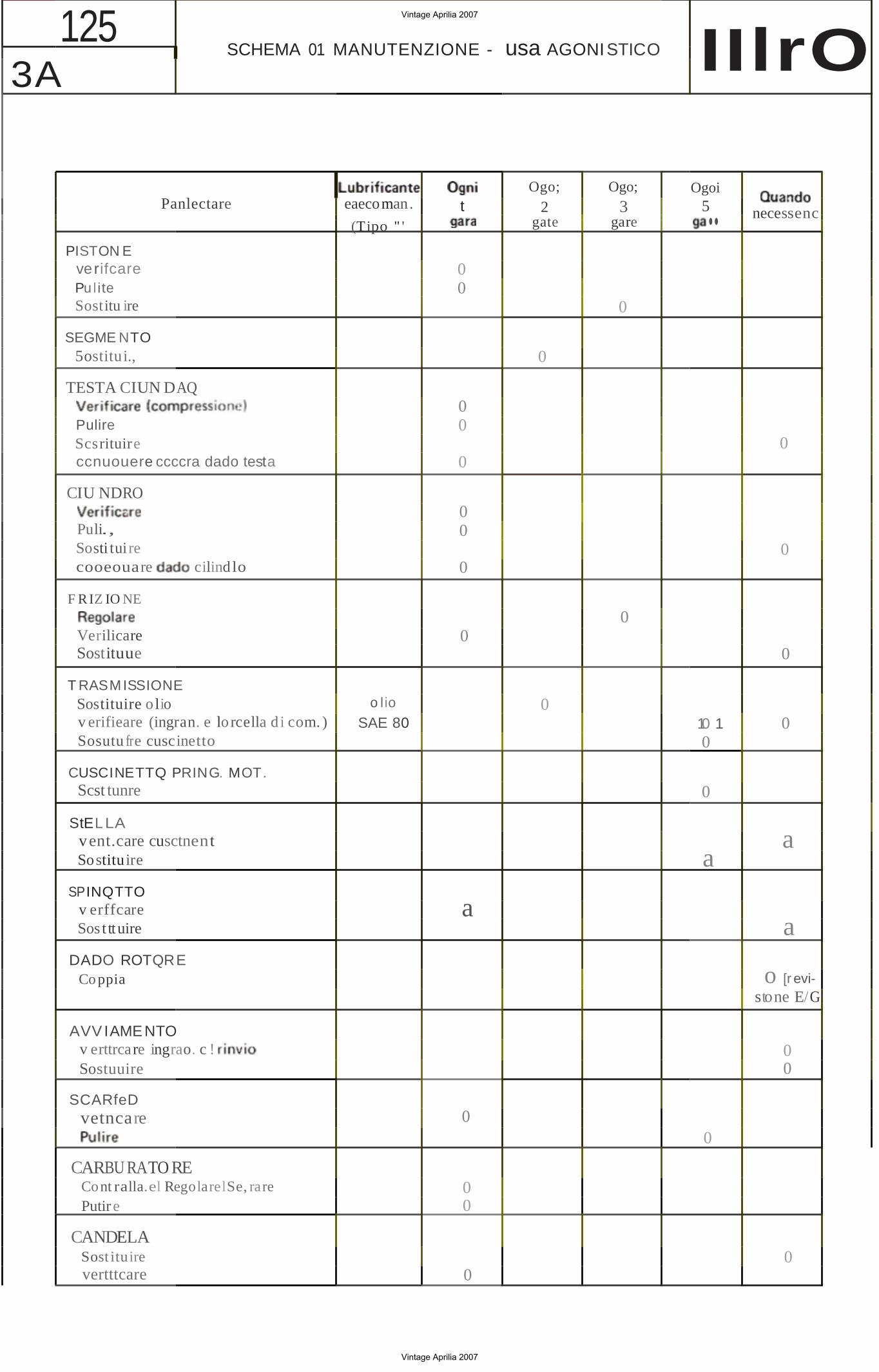
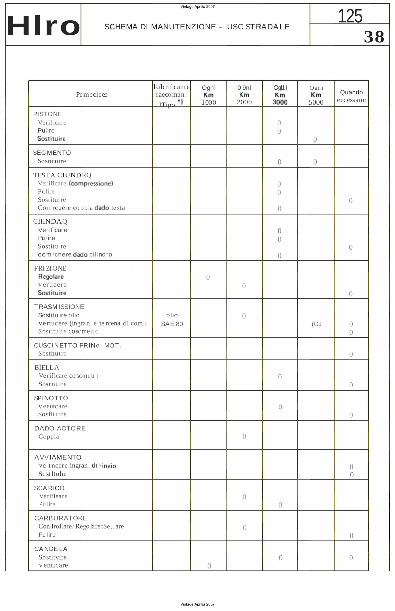
125 SCHEMA 01 MANUTENZIONE - usa AGONISTICO IIlrO3A
Panlectare
PISTON E verifcare Pu lite Sostitu ire
SEGME NTO 5ostitui.,
TESTA CIUN DAQ
Pulire Scsrituire ccnuouere ccccra dado testa
CIU NDRO
Puli., Sosti tui re cooeouare cilindlo
F RIZ IO NE
Verilicare Sostituue
T RASMISSIONE Sostituire o lio v erifieare (ingran. e lo rcella d i com. ) Sosutu fre cuscinetto
CUSCINETTQ PRING. MOT. Scst tunre
StELLA vent.care cusctnentSostituire
SPINQTTO v erffcare Sos t ttuire
DADO ROTQRE Co ppia
AVVIAMENTO v erttrcare ingrao. c ! Sostuuire
SCARfeD vetncare
CARBU RATO RE Cont ralla.el RegolarelSe, rare Putir e
CANDELASost ituirevertttcare
eaecoman.
(Tipo " '
o l io
SAE 80
t
00
00
0
00
0
0
a
0
00
0
Ogo;
2gate
0
0
Ogo;
3gare
0
0
Ogoi5..
10 1 0
0
a
0
necessenc
0
0
0
0
a
a
o [r evistone E/G!
00
0
Vintage Aprilia 2007
Vintage Aprilia 2007
38 Hlro SCHEMA DI MANUTENZIONE - USC STRADA LE
lubrificante Ogni 0 9ni Ogl1 i Pemccleee raeco man.
20001000ITipo PISTONE
Veril icare Pulire
$EG MENTO Sosntu tre
TESTA CIUNDRQ Ver ificare Pulire Sosriturre Comrcuere co ppia testa
ClllNDAQ Veri f icare Pul ire Sostitu-re ccm rcnere cil indro
.FRI ZIONE
v erueere
T RASM ISSIONE Sostitu ire o l io vertucere (ingran. e te rcena d i com.I Sost ituire coscrr eu c
CUSCIN ETTO PRINe. MOT. Scsthutre
BIELLA Veriflcare cosoneu t Sosrnuire
SPI NOTTO v eeutcareSosfit uire
DADO AOTORE Coppia
AVVIAMENTO ve-t ncere ingran. di Scst ltuhe
SCA RICO Ver ifiearePulire
CARBURATORE Con Irollare/ Rego larefSe,. are
00
0
00
0
0 0
0
0 0
olio 0 SAE 80
0
0
0
0 0
0 Pu l ire
CA NDE LA Sostitvire 0 v enticare 0
125
Ogn i Quando
eecessanc5000
0
0
0
0
0
(OJ 00
0
0
0
0 0
0
0
Vintage Aprilia 2007
Vintage Aprilia 2007
••
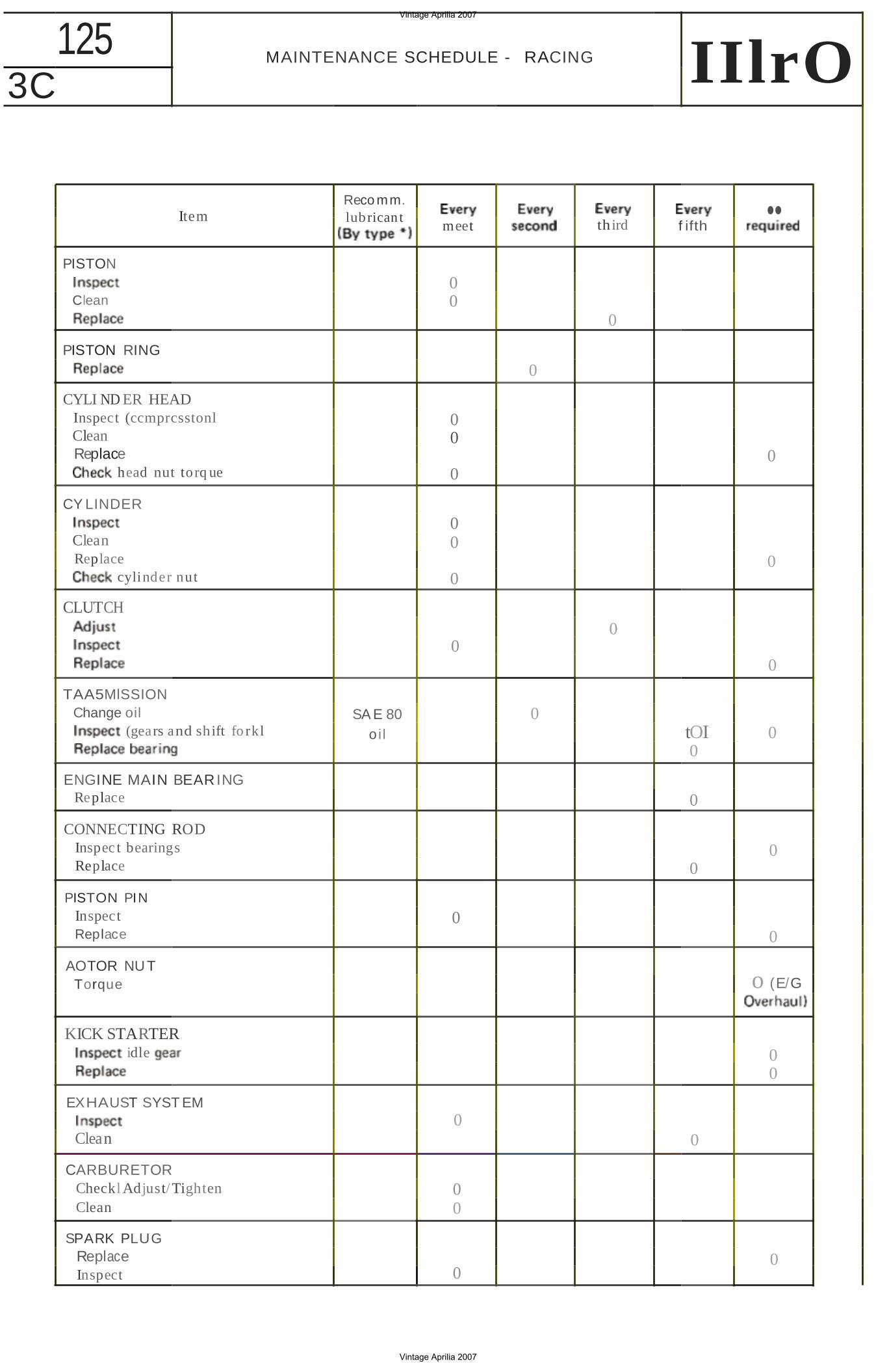
125 MAINTENANCE SCHEDULE - RACING IIlrO3C
Item
PISTON
Clean
PISTON RING
CYLI ND ER HEAD Inspect (ccmprcsstonl Clean Replace
head nut torq ue
CY LINDER
Clean Replace
cylinder nut
CLUTCH
TAA5MlSSION Change oil
(gears and shift fo rkl
ENGINE MAIN BEARING Replace
CONNECTING ROD Inspec t bearings Replace
PISTON PIN Inspect Replace
AOTOR NUT Torque
KICK STARTER idle
EXHAUST SYST EM
Clean
CARBURETOR Checkl Adjust/Tighten Clean
SPARK PLUG Replace Inspect
Reco mm. lubrican t
SA E 80oil
meet
00
00
0
00
0
0
0
0
00
0
third f ifth
0
0
0
0
0
0
0tOI 0 0
0
0 0
0
o (E/G
00
0
0
Vintage Aprilia 2007
Vintage Aprilia 2007
4 125
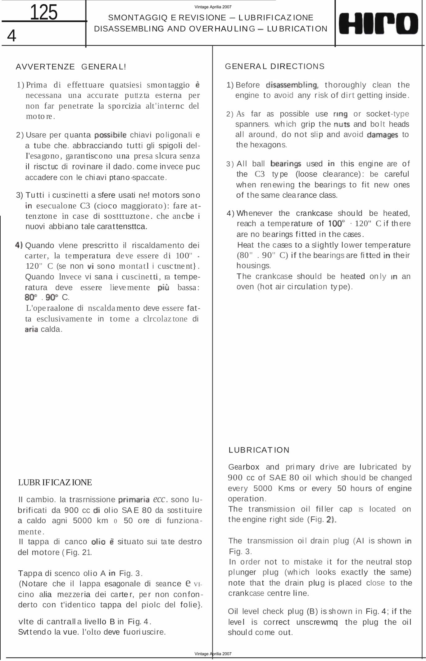
AVVERTENZE GENERA L!
1) Prima di effettuare quatsiesi smon taggio necessana una accu rate puttzta esterna per non far penetrate la spo rcizia alt 'internc del moto re .
2) Usare per quanta chiavi po ligonali e a tube che. abbracciando tutti gli spigoli delI'esagono , garantiscono una presa slcura senza il risctuc di rovinare i l dado. come invece puc accadere con le chi avi ptano -spaccate.
3) Tu tti i cuscinetti a sfere usati ne! motors sono esecualone C3 (cioco maggiorato): fare at
tenztone in case di sostttuztone . che ancbe i nuovi abbiano tale carat tensttca.
Quando vlene prescritto il riscaldamento dei carter, la temperatura deve essere di 100" 120" C (se non sono montat l i cusc tne nt} . Quando lnvece vi sana i cuscinet ti , ra temperatura deve essere lieve mente bassa :
. C. L'ope raalone di nscalda mento deve essere fatta esclusivamen te in tome a clrcolaz tone di
calda.
LUBR IFICAZ IONE
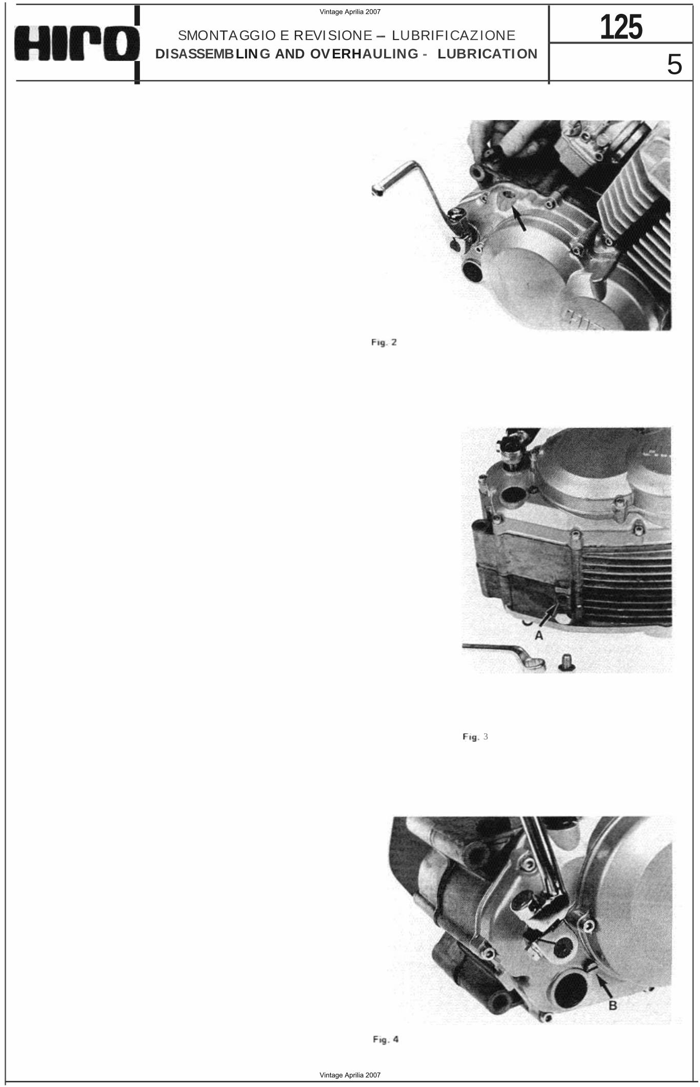
II cambio. la trasrnissione ecc. sono lubrificati da 900 cc ol io SA E 80 da sosti tuire a caldo agni 5000 km 0 50 ore di funzionamente . II tappa di canco situato sui ta te destrodel motore ( Fig. 21.
Tappa di scenco olio A Fig. 3.(Notare che il lappa esagonale di seance e VI
cino alia mezzeria dei carte r, pe r non con fonderto con t'iden tico tappa del piolc del fo lie}.
vlte di cantrall a livello B in Fig. 4 .Svt tendo la vue. l'olto deve fuori uscire.
SMONTAGGIQ E REVIS lONE L UBRIFICAZ IONEDISASSEMBLING AND OVERHAU LING LU BRICATION
GENERA L DIRECTIONS
1) Before thoroughly clean the engine to avoid any r isk of dirt getting inside.
2) As far as possible use or socket-type spanners. wh ich grip the and bo lt heads all around, do not slip and avoid to the hexagons.
3 ) All ball used this engine are o f the C3 ty pe (loose clearance) : be careful when renewing the bearings to fit new ones of the same clea rance class.
4 ) Whenever the crankcase should be heated, reach a temperature of · 120" C i f there are no bearings f i tted in the cases . Heat the cases to a sl ightly lower temperature (80" . 90" C) if the bearings are fi tted their housings. The crankcase should be heated on ly an oven (hot air ci rculation ty pe).
LUBRICAT ION
Gearbox and pri mary drive are lubricated by900 cc of SAE 80 oil which should be changedevery 5000 Kms or every 50 hours of engineoperation.The t ransmission oi l fil ler cap IS located onthe engine right side (Fig.
The transmission oi l drain plug (AI is shown Fig. 3.In order not to mistake i t for the neutral stopplunger plug (wh ich looks exactly the same)note that the drain plug is placed close to thecrankcase cent re line.
Oil level check plug (B) is sh own in Fig. 4; if theleve l is correct unscrewmq the plug the oi lshould come out.
Vintage Aprilia 2007
Vintage Aprilia 2007
5 125SMONTAGGIO E REVISIONE LUBRIFICAZIONE
DISASSEMBLING AND OV ERHAULING - LUBRICATION
3
Vintage Aprilia 2007
Vintage Aprilia 2007
8 125 CARBURATORE
CARBURETOR Hlro 21Avvi tare la vite A (Fig. 7) (regolazione vetvo!a
gas) fino ad ottene re un minima abbastanza alto.
3) Ruotare la vite B (Fig. 7) Ireqotanone miscela] fino ad ottenere la rotaziooe del motore piu vetoce e regolare possibne.
4 ) Svitare leggermente la vite A provocando un abbassamento del poi ructare co n precauzione ta vite B cercando sempre il regime di rotaziooe piu elevate e regolare. Agenda questa modo. altemativamente. suue due vi ti A e B. arrivare al regime min ima desi derata.
L1VE llATURA GAllEGGIANTE
Accertarsi che galleggian te sia del peso s tabilito ed Indicate sc uc stesso. non presenti alcuna deformazione e ruoti tiberamente sui suo perno. -Tenere i l ccrpc carbu ratore postztone ind io cata in modo che il bttenc tere galleggian te sia a leggero con tat to can 10 spillo e 10 spillo stesso con ta sede . In ques ta condizione con t rottare che i due semigalleggianti steno. rispetto al piano del co rpo. alia quota presc ritta (Fig.
2 ) Turn the throttle s top screw A (F ig. 7) crock. wise unt il the engi ne runs at a fast idle speed .
3 ) Turn the air adjusting screw B (Fig. 7) un til an even fast runnin g is obtained .
4 ) Slightly tu rn screw A an ticlockwise so that (he engine speed decreases, then carefully ad just screw B until the idle is even . Go on act ing on both screws in this way un ti l (he specified idle speed IS obtained .
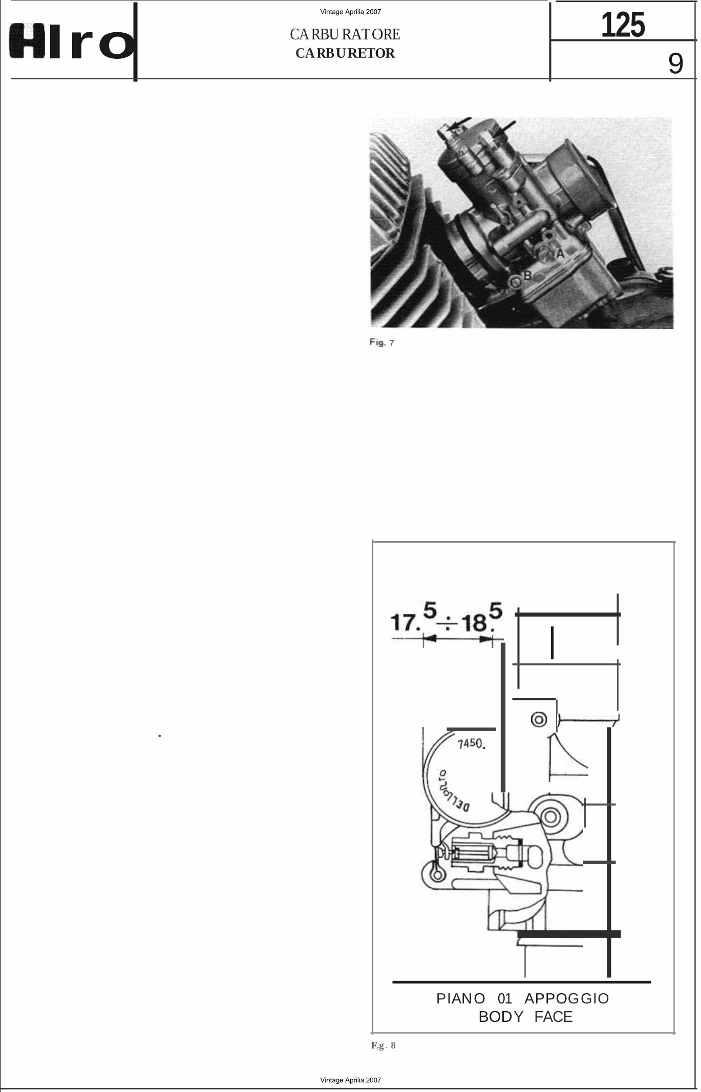
FLOAT LEV EL CHECK AND ADJUSTMENT
Make sure that the weight of the float is the one. (the weight is marked on the
floatl . tha t the float does not show any t race of warpage and tha t it moves freely on his pivo t.
Place the carburetor bod y in the pos it ion shown. so that the float arm is in ligh t contact with the need le valve and tha t the needle is contact with its seat .
The d istance be tween each o f the floats and the floa t bowl gaske t face o f the carburetor body shou ld coi ncide with the specif ied value (Fig. 8 ).
Vintage Aprilia 2007
Vintage Aprilia 2007
9 125CA RBU RATORE
CA RBURETORIro
•
7
PIANO 01 APPOGGIO BODY FACE
F.g . 8
Vintage Aprilia 2007
Vintage Aprilia 2007
10 125 IMPIAN TO E l ETTRI CO
ELECT RICA L SYSTEM IIlro
14
Vintage Aprilia 2007
Vintage Aprilia 2007
11 125IMPIANTO ElETTRI CO
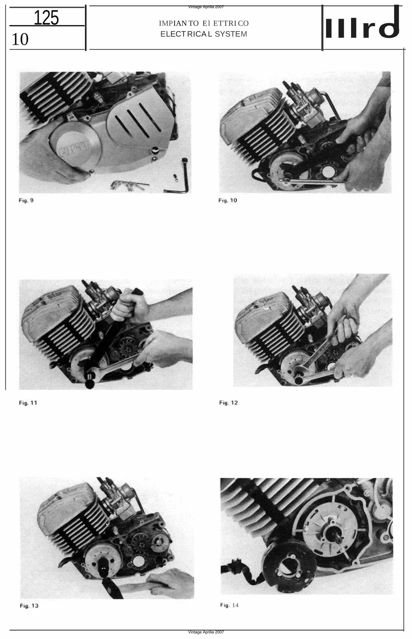
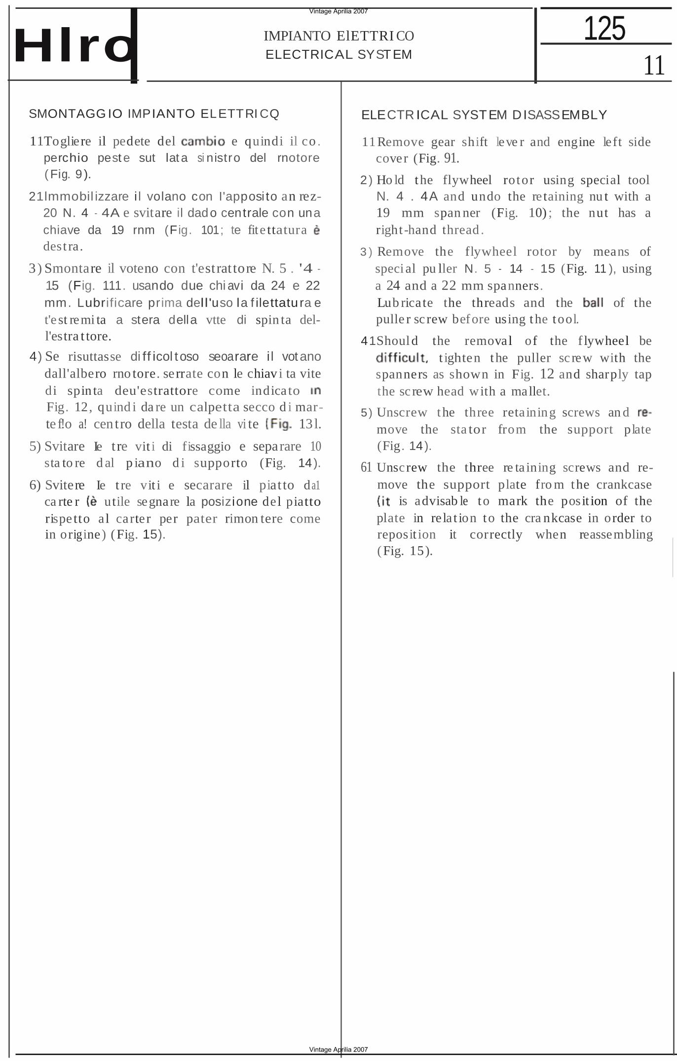
ELECTRICAL SYSTEMHlro SMONTAGG IO IMPIANTO ELETTRI CQ
11Togliere il pedete del e quindi il co . perchio pest e sut lat a si nistro del rnotore ( Fig. 9 ).
21lmmobil izzare i l volano con I'apposi to an rez20 N. 4 4A e svitare il dado centrale con una chiave da 19 rnm (Fig. 101; te fit e ttatura dest ra.
3 ) Smontare il voteno con t'estrat tore N. 5 . '4 15 (Fig. 111. usando due chi avi da 24 e 22 mm. Lubrificare prima dell'uso la f ilettatu ra e t'e st remi ta a stera della vtte di spin ta dell'estra t tore.
4) Se risuttasse di ff icol t oso seoarare i l vot ano dall'albero rno tore. serrate con le chiav i ta vite di spin ta deu'estrattore come indica to Fig. 12, quind i da re un calpetta secco d i marte f!o a! cen tro della testa de lla vi te 13 l.
5) Svitare Ie t re vit i di fissaggio e separare 10 sta to re d al p iano d i supporto (Fig. 14).
6) Svitere Ie t re vit i e secarare il piat to da1 ca rte r utile segnare la posizione del piatto rispetto a l carte r per pater rimon tere come in origine) (Fig. 15).
ELECTR ICAL SYSTEM D ISASSEMBLY
11Remove gear shift leve r and engine left side cover (Fig. 91.
2) Ho ld the flywheel rotor using special tool N. 4 . 4A and undo the re taining nu t with a 19 mm span ner (Fig. 10) ; the nut has a right -hand thread .
3 ) Remove the flywheel rotor by means of speci al pu ller N. 5 14 15 (Fig. 11 ), usinga 24 and a 22 mm spanners.Lub rica te the threads and the of thepulle r sc rew before using the tool.
41Should the removal of the f lywheel be t ighten the puller sc rew with the
spanners as shown in Fig. 12 and sharply tap the sc rew head with a mallet.
5) Unscrew the three reta ining screws an d move the sta tor from the support plate (Fig. 14).
61 Unscrew the three re ta ining screws and remove the support plate fro m the crankcase
is advisab le to mark the posit ion of the plate in re la t ion to the cra nkcase in order to reposit ion it correctly when reassembling (Fig. 15).
Vintage Aprilia 2007
Vintage Aprilia 2007
12 125 IMPIANTQ ELETTRICO
EL ECTRICA L SYSTEM Hlro V ERI FI CA IMPIA NTO 01 ACCENSIONE
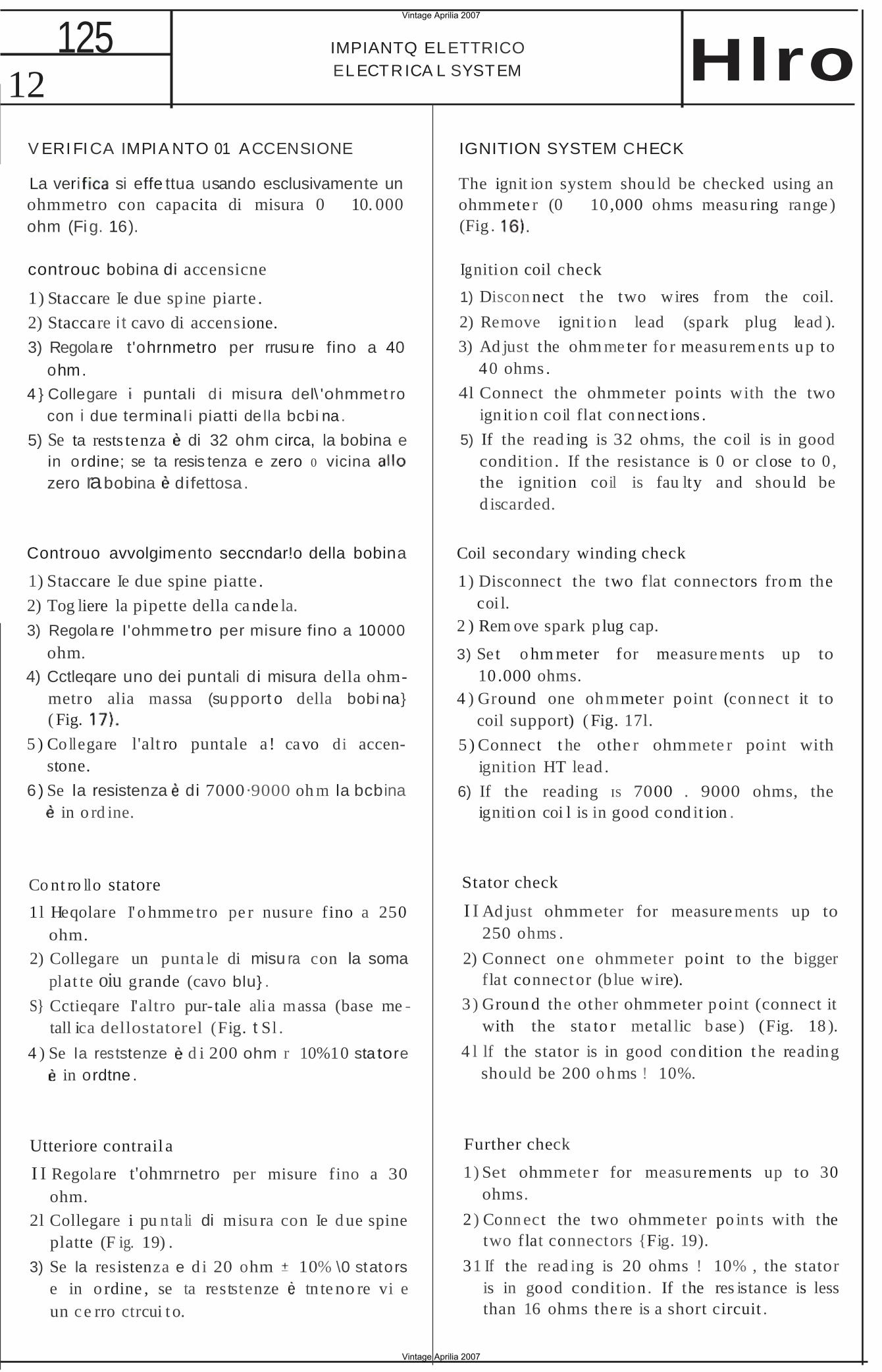
La veri si effe ttua usando esclusivamente un ohmmetro con capacita di misura 0 10. 000 ohm (Fig. 16).
controuc bobina di accensicne
1) Staccare Ie due spine piarte .
2) Staccare i t cavo di accensione.
3) Regola re t'ohrnmetro per rrusu re fino a 40 ohm.
4 } Collegare puntali d i misu ra del\ 'ohmmet ro con i due termina l i piatti de lla bcbi na .
5) Se ta rests tenza di 32 ohm circa, la bobina e in ordine; se ta resis tenza e zero 0 vicina zero rabobina difettosa .
Controuo avvolgimento seccndar!o della bobina
1) Staccare Ie due spine piatte .
2) Tog liere la pipette della ca nde la.
3) Regola re I'ohmmetro per misure fino a 10000
ohm. 4) Cctleqare uno dei puntali di misura della ohm
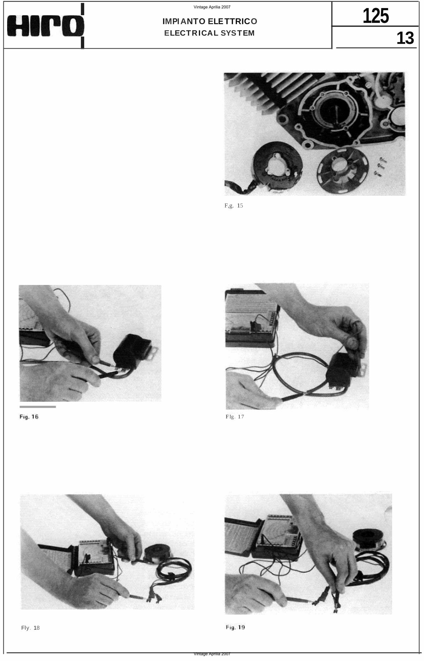
metro alia massa (support o della bobi na} ( Fig.
5 ) Co llegare l'alt ro puntale a! cavo di accenstone.
6 ) Se la resistenza di 7000·9000 oh m la bcbina in o rd ine.
Co nt ro llo statore
1l Heqolare I' o hmme tro pe r nusure fino a 250 ohm.
2) Collegare un punta le di misu ra con la soma plat te oiu grande (cavo blu} .
S} Cctieqare I'altro pur- tale alia massa (base me tall ica dellostatorel (Fig. t Sl .
4 ) Se la reststenze d i 200 ohm r 10%10 sta tore in ordtne .
Utteriore contrail a
I I Regola re t'ohmrnetro per misure fino a 30 ohm.
2l Collegare i pu n ta li di misu ra con Ie d ue spine platte (F ig. 19) .
3) Se la resistenza e d i 20 ohm 10% \0 stators e in o rdine , se ta reststenze tn te no re vi e un c e rro ctrcui t o.
IGNITION SYSTEM CHECK
The ignit ion system shou ld be checked using an ohmmete r (0 10,000 ohms measu ring range ) (Fig .
Ignition coil check
1) Discon nect t he two wires from the coil.
2) Remove igni t io n lead (spark plug lead ).
3) Ad just the ohm me ter fo r measu rem en ts u p to 40 ohms .
4l Connect the ohmmeter points with the two ign it io n coil flat con nect ions .
5) If the read ing is 32 ohms, the coil is in good condition . If the resistance is 0 or close to 0 , the ignition coil is fau lty and shou ld be d iscarded.
Coil secondary winding check
1) Disconnect the two flat connectors fro m the coi l.
2 ) Rem ove spark p lug cap.
3) Set o hm meter for measure ments up to 10 .000 ohms.
4 ) Ground one oh mmeter point (connect it to coil support) ( Fig. 17l.
5 ) Connect t he othe r ohmmete r point with ignition HT lead .
6) If the reading IS 7000 . 9000 ohms, the ignition coi l is in good cond it ion .
Stator check
I I Ad just ohmmeter for measure ments up to 250 ohms .
2) Connect on e ohmmeter point to the bigger flat connect or (b lue wire).
3 ) Groun d the other ohmmeter point (connect it with the sta to r metal lic base ) (Fig. 18 ).
4 l lf the stator is in good con dition t he reading should be 200 o hms ! 10%.
Further check
1) Set ohmmete r for measu rements up to 30 ohms.
2 ) Conn ect the two ohmmeter po in ts with the two flat connectors {Fig. 19).
31 If the read ing is 20 ohms ! 10% , the stator is in good condition . If the res istance is less than 16 ohms the re is a short circuit .
Vintage Aprilia 2007
Vintage Aprilia 2007
13 125IMPI ANTO ELETTRICO
ELECTRICAL SYSTEM
F,g. 15
F Ig . 1 7
Fly. 18
Vintage Aprilia 2007
Vintage Aprilia 2007
14 125 IMPIANTO ELETTRI CO
ELECTRICAL SYSTEM Iro
-Fig.20 f ,g.
•• •
F,g. 24
Vintage Aprilia 2007
Vintage Aprilia 2007
15 125IMPIANTQ ElETTRICO
ELECTRICAL SYSTEM
MONTAGG IO·MESSA IN FASE IMPIANTO ACCENSIONE
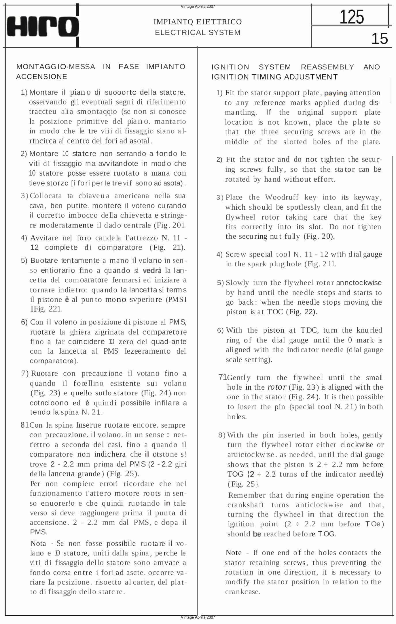
1) Montare il pian o di suooortc del la statc re. osservando gl i even tuali segn i di riferi men to traccteu ali a smontaqqio (se non si conosce la posizione primitive del pian o. manta rio in modo che le tre vii i d i fissaggio siano a lrtncirca a! centro del fori ad asotal .
2) Montare 10 statc re non serrando a f ondo Ie viti d i f issaggio rna avvitandote in mod o che 10 statore posse essere ruotato a mana con tieve storzc [ i fo r i per Ie tre vif sono ad asota) .
3) Collocata ta cbiave u a americana nella sua cava , ben putite. montere il voteno cu rando
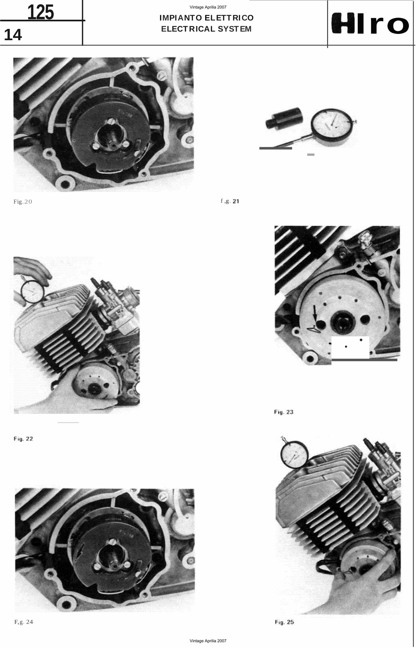
corret to imbocco de lla chievetta e stringere moderatamente il dad o cent rale (Fig . 20 1.
4) Avvitare nel fo ro cande la l'att rezzo N. 11 12 comple te d i comparatore (Fig. 21).
5) Buotare tentamente a mano il vclano in sen 50 entiorario fino a qu ando si la Iance tta del comoaratore fermarsi ed iniziare a tornare indie t ro: qua ndo la lancet ta si term s il pistone al pun to mono svperio re (PMSI IFig. 221.
6) Con i l voleno in posizione d i pistone al PMS, ruotare la ghiera zigrinata del ccmparetore fino a far coincidere 10 zero del quad-ante con la Iancetta al PMS Iezeeramento del cornpa ratcre).
7) Ruotare con precauz ione il votano fino a q uando il fo re llino esistente sui volan o (Fig. 23) e quel!o sutlo statore (Fig. 24 ) non cotncioono ed quind i possibile infila re a tendo la spina N. 21.
81Con la spina Inserue ruota re encore. sempre con precau zione. i l volano. in un sense 0 ne tt'ett ro a seconda del casi. fino a quando il comparatore non indichera che otstone s! trove 2 - 2.2 mm prima del PMS (2 - 2.2 gir i della lanceua grande ) (Fig. 25). Per non comp iere error! ricordare che nel funzionamento t' attero motore roots in senso enuorer!o e cbe quindi ruotando ta le verso si deve raggiungere prima il pun ta d i accensione . 2 - 2.2 mm dal PMS, e dopa il PMS.
Nota · Se non fosse possibile ruota re vola no e 10 statore, uniti dalla spina , pe rche le vi t i d i fissaggio del lo sta tore sono amvate a fondo corsa en tre i fori ad ascte. occor re variare Ia pcsizione . risoetto al carte r, del pla t to di f issaggio de ll o s tatc re.
IGNITI ON SYSTEM REASSEMBLY ANO IGNITI ON TIMING ADJUSTMENT
1) Fit the stator support plate, attention to any reference marks applied during disma ntling . If the original suppo rt plate locat ion is not known , place the p la te so tha t the th ree secu ring screws are in the middle of the slotted holes of the plate.
2) Fit the sta tor and do not t ighten the secu ring screws fully , so that the sta tor can be rota ted by ha nd without effort.
3 ) Place the Woodruff key into its keyway , which should be spotlessly clean, and fit the flywheel rotor taking care tha t the key fits correc tl y into its slot. Do not t ighten the secu ring nu t fu lly (Fig. 20).
4) Screw special too l N. 11 - 12 with d ial gauge in the spark p lug hole (Fig. 2 11.
5) Slowly turn the flywheel rotor annctockwise by hand until the nee dle stops and starts to go back : when the needle stops moving the piston is a t T OC (Fig. 22).
6) With the piston a t T DC, tu rn the knu rled ring o f the d ial gauge unt il the 0 mark is aligned with the indi cator needle (d ial gauge scale se tt ing).
71Gentl y turn the fly wheel until t he small hole in the rotor (Fig. 23 ) is al igned with the one in the stato r (Fig. 24 ). It is then possible to insert the pin (special tool N. 21) in both holes.
8) Wi th the pin inserted in both holes, gently turn the flywhee l rotor e ither clockwise or aruictockwtse . as nee ded , until the dial gauge shows that the pist on is 2 2.2 mm be fore TOG 2.2 turn s of the indicator need le) (Fig. 25 }.
Rem ember tha t du ring engine operation the cranksha ft turns anticlockwise and that , turning the flywhee l that di rec t ion the ignition point (2 2 .2 mm before T Oe ) should reached befo re T OG.
Note - If one end o f the holes contacts the sta tor retaining screws , thus preventing the rota t ion in one d irection, it is necessary to modify the sta tor position in re lation to the crankcase.
Vintage Aprilia 2007
Vintage Aprilia 2007
16 125 IMPIANTO ELETTR ICO
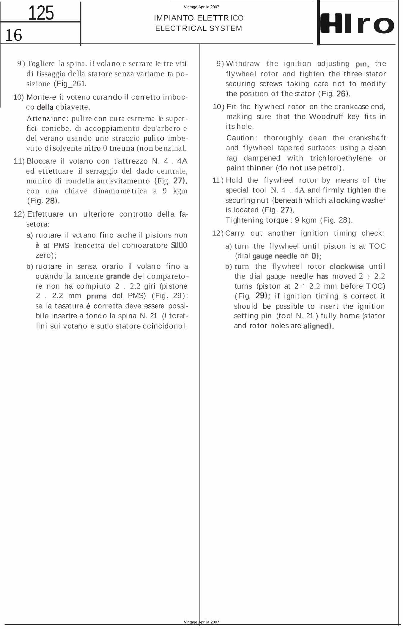
ELECT RICAL SYSTEM Iro 9 ) Togliere la sp ina. i ! volano e ser ra re Ie t re viti
di fissaggio della statore senza variame ta posizione (Fig_261.
10) Monte-e it voteno curando corretto irnbocco cbiavette. Attenz ione: pulire con cu ra es rrema Ie super fici conicbe. di accoppiamento deu'ar bero e del verano usando uno straccio puli to imbevu to d i solvente nitro 0 tneuna (non be nzinal.
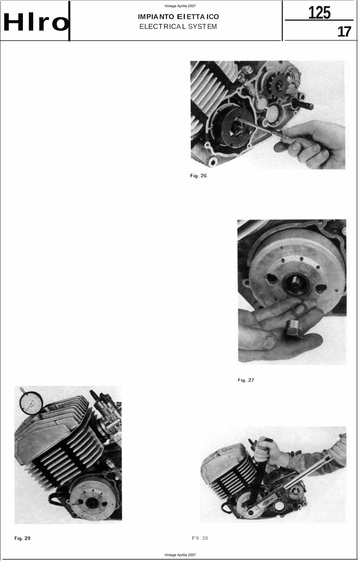
11) Bloccare il votano con t'at t rezzo N. 4 . 4A ed effettuare il serraggio del dado centrale, mu nito di rondella an t isvitamento {Fig. con una chiave d inamo me tr ica a 9 kgm (Fig.
12) Etfettuare un u lteriore con trotto dell a fasetora: a) ruotare il vct ano f ino ache il pistons non
at PMS Itencetta del comoaratore suuo zero);
b) ruotare in sensa orario il volano fino a quando la rancene del comparetore non ha compiuto 2 . 2.2 gir i (pi stone 2 . 2.2 mm del PMS) (Fig. 29) : se la t asatura corretta deve essere possibi le insertre a fondo la spina N. 21 (! tcret lini sui votano e sut!o stat ore ccincidono l .
9 ) Withdraw the ignition adjusting the flywheel rotor and t ighten the three stator securing screws taking care not to modify
position o f t he stator (Fig.
10 ) Fi t the fly wheel rotor on t he crankcase end, making sure that the Woodruff key fi ts in i ts hole.
Caution : thoroughly dean the cranksha ft and f lywheel tapered surfaces using a clean rag dampened with tr ich loroethylene or paint thinner (do not use petrol) .
11 ) Hold the f lywheel rotor by means of the special t oo l N. 4 . 4A and f irmly t ighten the securing nu t {beneat h wh ich a is located (Fig. Ti ghtening torque : 9 kgm (Fig. 28).
washer
12 ) Carry out another ignition t iming check :
a) turn the f lywheel unti l piston is at TOC (dial on
b) turn the flywheel ro tor unti l the d ial gauge needle moved 2 2.2 turns (pis ton at 2 2.2 mm before T OC) (Fig. i f ignit ion timi ng is correct it should be poss ible to inse rt the ignition setting pin (too! N. 21 ) fu lly home (s tator and ro tor holes are
Vintage Aprilia 2007
Vintage Aprilia 2007
17 125IMPIA NTO ElETTA ICO
ELECTRICA L SYSTEMHlro
F' lI. 28
Vintage Aprilia 2007
Vintage Aprilia 2007
125 18
TESTA CILI ND RO PI STONE CYLIN DER HEAD - CY LINDER - PISTON Hlro
Fig.
Fig . 3 1
32
Fig. 33
Fig. 35
Vintage Aprilia 2007
Vintage Aprilia 2007
Iro SMONTA GGIO TESTA
TESTA - CILINDRO PISTONE CY LI NDER HE AD - CYLINDER - PISTON
CY LI NDER HEAD REMOVAL
125 19
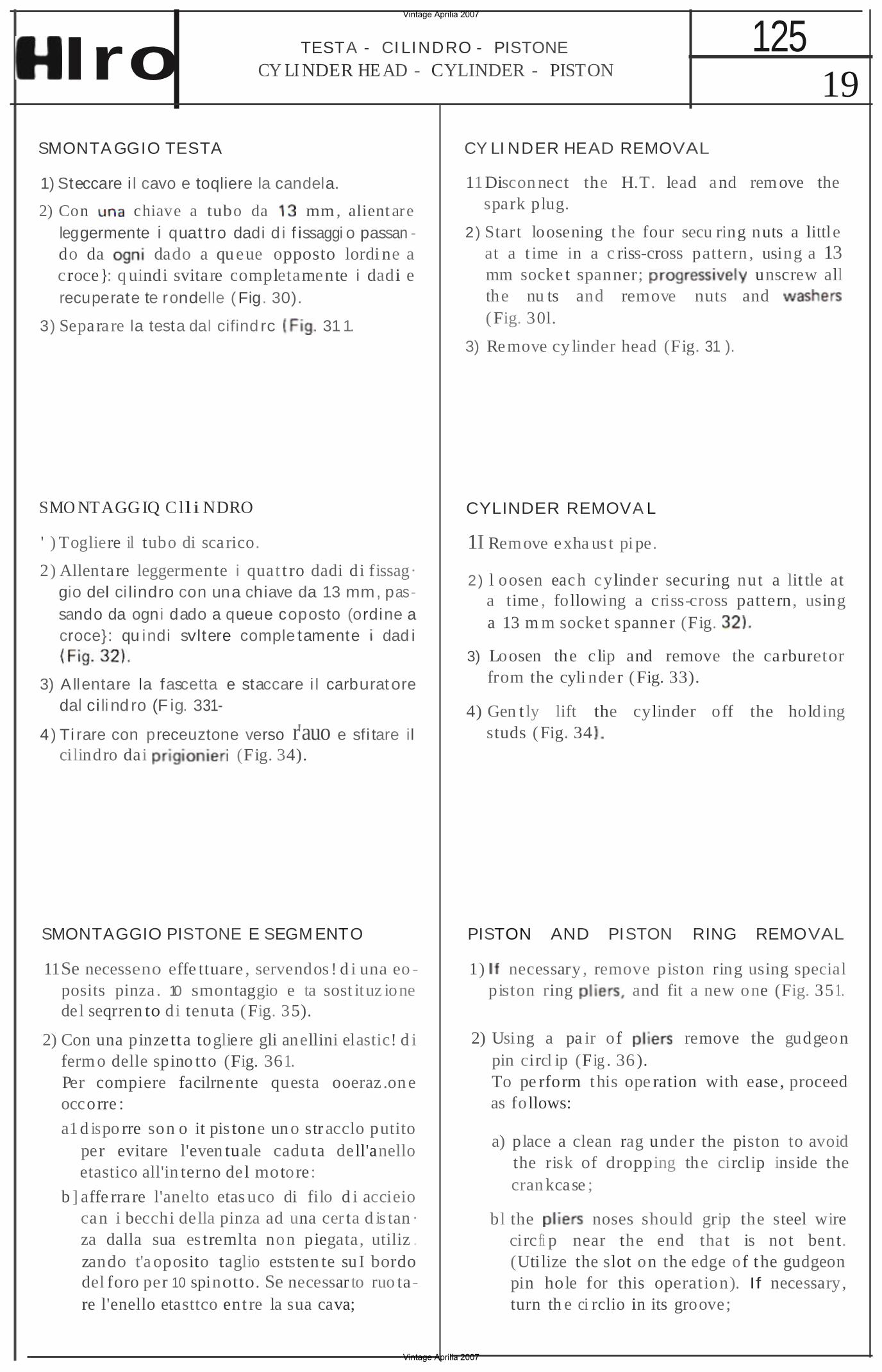
1) Steccare i l cavo e toqliere la candela.
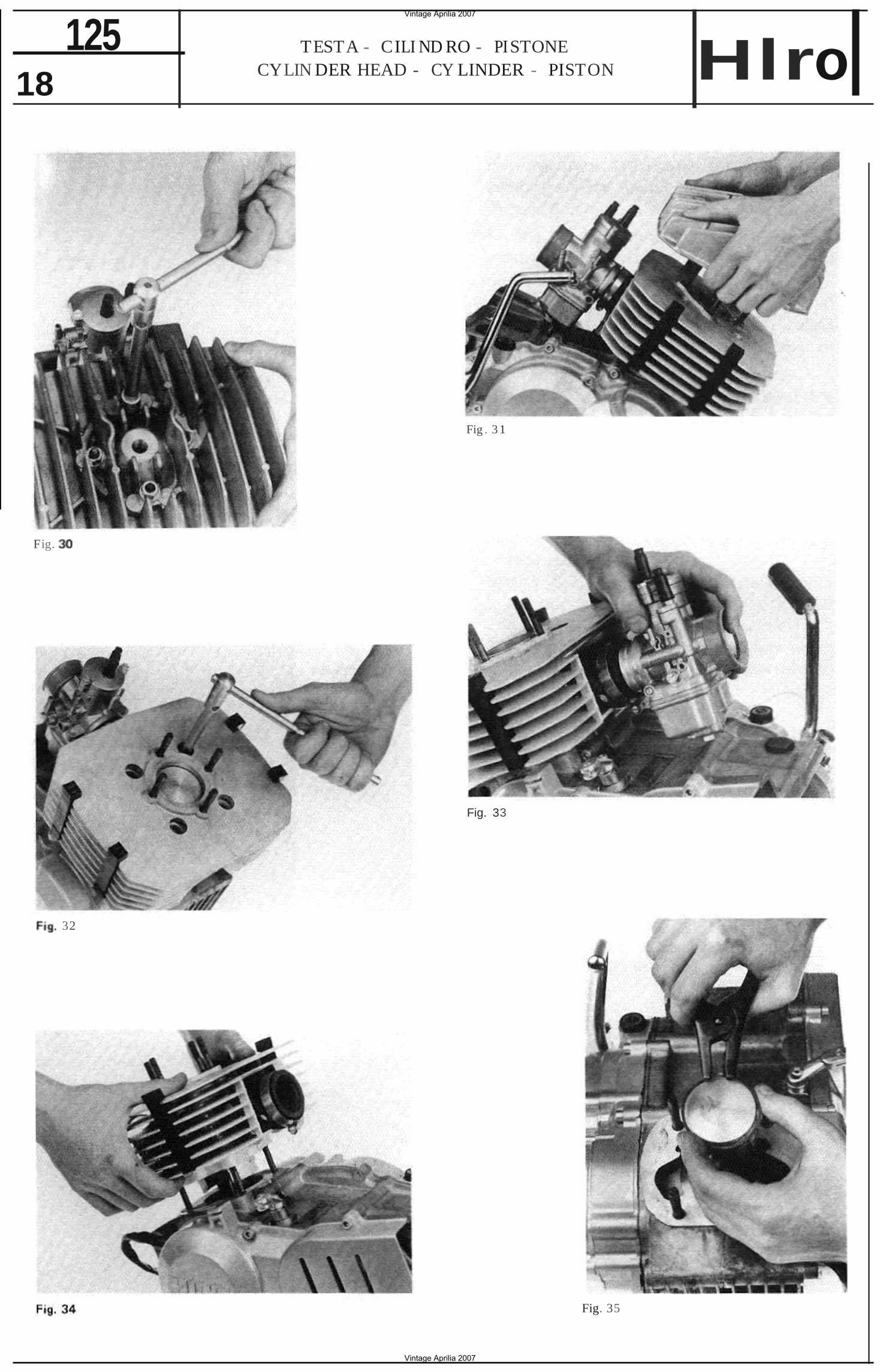
2) Con chiave a tubo da mm , alient are leggermente i quat tro dadi d i f issaggi o passan do da dado a queue opposto lordi ne a croce}: q uindi svitare completamente i dadi e recuperate te rondelle ( Fig. 30).
3) Separare la testa dal cifind rc 31 1.
SMO NTAGG IQ C lli NDRO
' ) Togliere il tubo di scarico.
2) Allenta re leggermente i quat t ro dadi di fissag· gio del ci lindro con una chiave da 13 mm, passando da ogni dado a queue coposto (ordine a croce}: qu indi svltere comple tamente dad i
3) A llentare la fascetta e staccare i l carburatore dal ci li nd ro (F ig. 331
4 ) Ti rare con preceuztone verso r'auo e sfi tare il cilindro dai (Fig. 34).
SMONTAGGIO PISTONE E SEGM ENTO
11Se necesseno effe ttuare , servendos ! d i una eo posits pinza . 10 smontaggio e ta sost ituz ione del seqrren to di tenuta (Fig. 35).
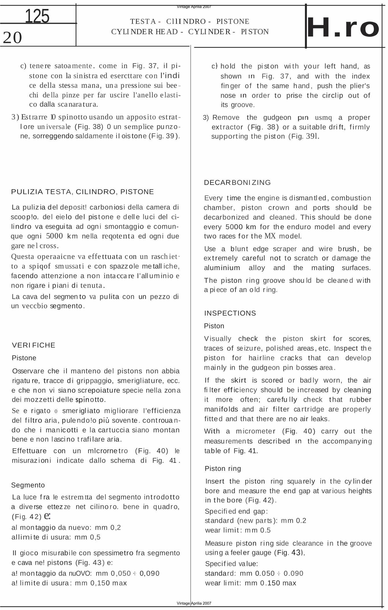
2) Con una pinzetta toglie re gli anellini elastic! d i ferm o delle spino tto (Fig. 361. Per compiere facilrnente questa ooeraz .on e occorre :
a1d ispo rre son o it pis tone un o str acclo putito per evitare l'even tuale cadu ta dell'anello etastico all'in terno del motore:
b ] affe rra re l'anelto etas uco di filo d i accieio can i becchi della pinza ad una cer ta d is tan · za dalla sua es tremlta non piegata, utiliz . zando t'a oposito taglio eststen te suI bordo del foro per 10 spinotto. Se necessar to ruo tare l'enello etasttco ent re la sua cava;
11 Discon nect the H.T. lead and rem ove the spark plug.
2) Start loosening the four secu ring nuts a little at a t ime in a c riss-cross pattern , using a 13 mm socke t spanner; unscrew all the nu ts and remove nuts and (Fig. 30l.
3) Remove cy linder head (Fig. 31 ).
CYLINDER REMOVA L
1I Remove exha us t pipe.
2) l oosen each cylinder securing nut a lit tle at a time , following a c risscross pattern, using a 13 m m socke t spanner (Fig.
3) Loosen the c lip and remove the carburetor from the cyli nder (Fig. 33).
4) Gen t ly lift the cylinder off the holding studs (Fig. 34
PISTON AND PISTON RING REMOVAL
1) necessary , remove piston ring using special piston ring and fit a new one (Fig. 351.
2) Using a pa ir of remove the gudgeon pin circl ip (Fig . 36). To pe rform this ope ration with ease , proceed as follows:
a) place a clean rag under the piston to avoid the risk of dropping the circlip inside the cran kcase ;
bl the noses should grip the steel wire circ fi p near the end tha t is not bent. (Utilize the slot on the edge of t he gudgeon pin hole for this operation). If necessary, turn th e ci rclio in its groove;
Vintage Aprilia 2007
Vintage Aprilia 2007
20 125 TEST A - Cl lI NDRO - PISTONE
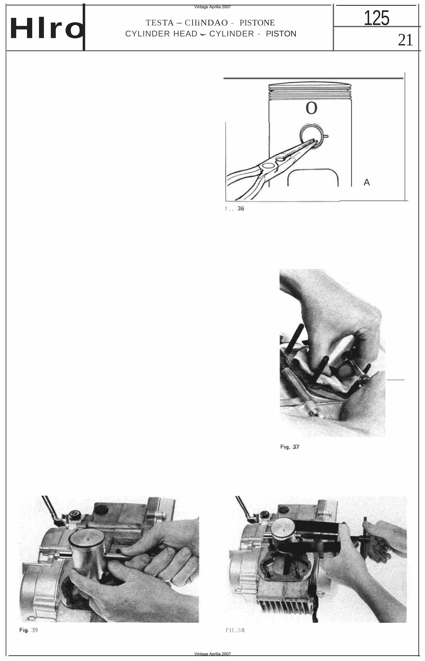
CYLI NDE R HE AD - CYLI NDE R - PI STON H.ro c) tene re satoa mente . come in Fig. 37, i l p i
stone con la sinist ra ed esercttare con l'indi ce della stessa mana, un a pressione sui bee chi de lla pinze per far uscire l'anello e lastico dalla scanara tura.
3 ) Est rarre 10 spinotto usando un apposito est rat l ore un iversale (Fig. 38) 0 un semplice pu nzone, sorreggendo saldamente i I ois tone (F ig. 39 ).
PULIZIA TESTA, CILINDRO, PISTONE
La puliz ia del deposit! carbon iosi della camera di scoop!o. del eielo del pis t one e dell e luci del ciIindro va esegui ta ad ogn i smontaggio e comunque ogn i 5000 k m nella reqotenta ed ogn i due gare ne l cross.
Questa operaaicne va effe ttuata con un rasch iet· to a sp iqof sm ussat i e con spazzole me tall iche, facendo attenzione a non intacca re I'all um inio e non rigare i p iani di tenuta .
La cava del segmen to va pu lita con un pezzo di un veccbio segmento .
VERI FICHE
Pistone
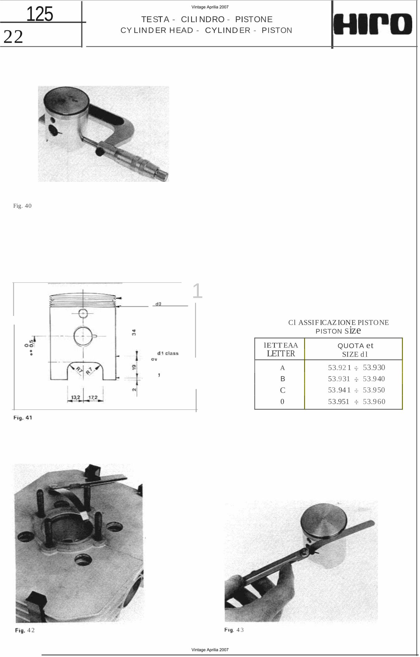
Osservare che i l manteno del pistons non abbia rigatu re, tracce d i grippaggio, smerigl iature, ecc. e che non vi siano screpoiature specie nella zona dei mozzett i delle otto.
Se e r igato 0 smer igl iato migl iorare I'eff icienza del f i ltro aria, pule ndo!o sovente . cont roua ndo che i manicotti e la cartuccia siano montan bene e non lasci no t rafi lare aria.
Effettuare con un mlcrorne tro (Fig. 40) Ie misuraz ion i indicate dallo schema di Fig. 41 .
Segmento
La luce f ra Ie estrem tta del segmento in t rodotto a dive rse ettez ze net cilino ro. bene in quadro, (Fig. 4 2) e: al mon taggio da nuevo: mm 0,2 allimi te di usura: mm 0,5
II gioco misu rabi le con spessimetro fra segmento e cava ne! pistons (Fig. 43 ) e:
a! mon taggio da nuOVO: mm 0 ,050 0,090 a! limi te di usura : mm 0,150 max
ho ld the pi st on wi th your left hand, as shown Fig. 37, and with the index fin ger of t he same hand , push the plier's nose order to prise t he circl ip out of its groove.
3) Remove the gudgeon usmq a proper ext ractor ( Fig. 38 ) or a suitable dri ft, f i rmly support ing the pist on (Fig. 39l.
DECARBONI ZING
Every t ime the engine is disman tl ed , combustion chamber, piston crown and ports should be decarbonized and cleaned. This should be done every 5000 km for th e enduro model and every two races f or t he MX model.
Use a blunt edge scraper and wire brush , be ex t remely careful not to scratch or damage the aluminium alloy and the mating surfaces.
The piston r ing groove shou ld be cleane d w ith a pi ece of an o ld r ing.
INSPECTIONS
Piston
V isually check th e piston skirt for scores, traces of se izu re, pol ished areas , etc. Inspect th e piston for hai r line cracks that can develop mainly in the gudgeon pin bosses area .
If the skirt is scored or bad ly worn, the air fi lter eff ic iency shou ld be increased by clean ing it more often; carefu l ly check t hat rubber man ifo lds and ai r f i lter ca rtr idge are properly fitted and that there are no air leaks.
With a m icrometer (Fig. 40 ) carry out the measuremen ts described the accompany ing table of Fig. 41.
Piston ring
Insert the piston ring squarely in t he cy lin der bore and measure the end gap at var ious heights in t he bore (Fig. 42) .
Specifi ed end gap: standard (new par ts ): mm 0.2 wear limi t : m m 0.5
Measure piston r ing side clearance in t he groove using a feeler gauge (Fig.
Specif ied va lue: standard: mm 0.050 0.090 wear li mit: mm 0 .150 max
Vintage Aprilia 2007
Vintage Aprilia 2007
Hlro TESTA ClliNDAO PISTONE CYLINDER HEAD CYLINDER - PISTON
125 21
o
f ...
39 f'1l ,38
A
Vintage Aprilia 2007
Vintage Aprilia 2007
••
• •
22 125 TESTA - CILI NDRO - PISTONE
CY LIND ER HEAD - CYLIND ER - PISTON
Fig. 40
1
,
Cl ASSIF ICAZ IONE PISTONE
lETT EAALETTER
A
B
C0
PISTON sizeQUOTA et
SIZE d l
53.92 1 53.93053.931 53.9 40
53.94 1 53.950
53.951 53.960
4 2 4 3
Vintage Aprilia 2007
Vintage Aprilia 2007
23 125T ESTA - C ILl NDRO - P ISTON E
CY LIN DE R HEAD - CYLIN DER - P ISTON
44
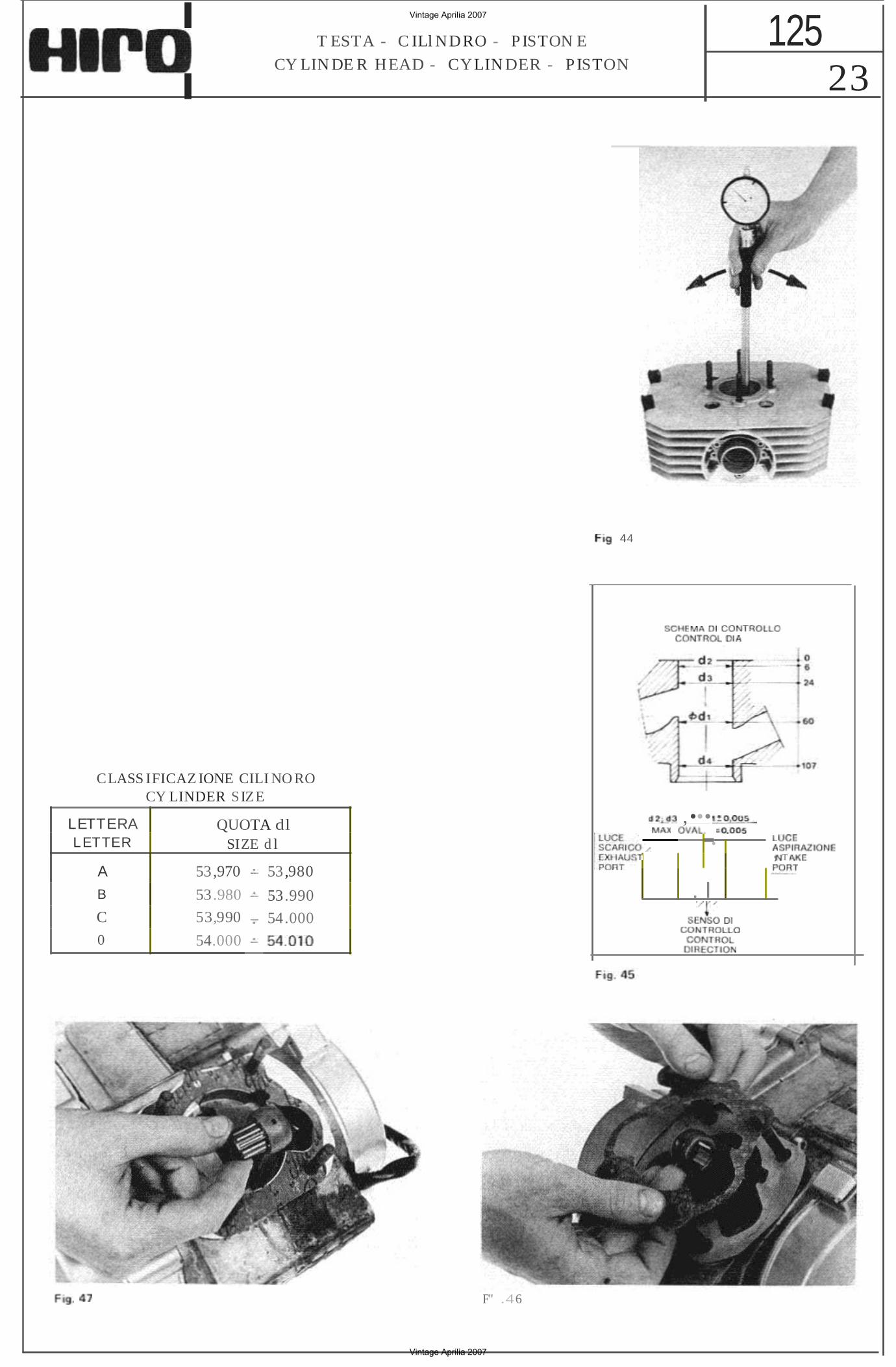
CLASS IFICAZ IONE CILI NO ROCY LINDER SIZE
LETTERA L ETTER
QUOTA dl SIZE d l
A 53,970 53,980
B 53.980 53.990 C 53,990 54.000 0 54.000
GIl .....
T
, •••• ,
. I
F" .46
Vintage Aprilia 2007
Vintage Aprilia 2007
24 125 TESTA - CILINDRO - PISTONE
CY LINDE R HEAD - CYLINDE R - PISTON Hlro
49
SO
Vintage Aprilia 2007
Vintage Aprilia 2007
Iro T ESTA - CllI NDRQ - PISTO NE
CY LINDER HEA D - CY LINDE R PISTON
125 25
Cilindro
Osservare se la superficie intema del cilindro s! presents leviqata 0 se con r igature. d i usura 0 d i grippaggio 0 add iri t tu ra con zone maocant! del nvestimento d i creme (il cif indro rio crorrebttel. Et te ttu are median te alesarne tro ( Fig. 44) le misuraz ion i ind icate da llo schema di Fig. 45.
Cy l inder
The cy l inder bore shou ld be visually inspected for scores. traces of wear or seizure, or damages to the chrome p lated surface. (The cy l inder bore can be re.ptetedl . Using a cylinder gauge (Fig. 44 ) carry out the measu rements referrin g to the tab le o f Fig. 45.
MONTAGGIQ
1) Montare ta guarn izione di base del cil ind ro I Fi g. 4 61. La scessore di ta le guarnizione di 0 ,5 mm.
2) Porre net piede di biella ra qabbia a rulti, oliandcla rnode ratamente (Fig. 4 71.
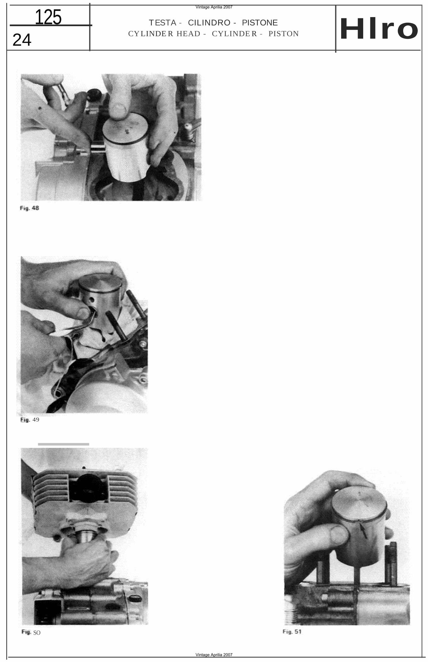
3) Montare i l oistone: t'tn troduzi ooe soi none. leggermen te tubnttcato. va effettuato a mana e non oresente di fficol ta. Non usare mai it martell o per compie re qu esta operazio ne. E' tmconan te osservare il verso di mc n taqqlo del ptstone: la treccia deve essere dire tta verso la parte anteriore del motore ctoe nel verso di avanzamento della mote (F ig. 48).
4 ) Con l'aiutc di una pinza a becchi montare due anell i elastici di fermo de lle spin otto (no tare la posizione del pol lice della mano sini. st ra e 10 straccio per impedire t'eventoete cadu ta dell'anello al l 'i nterno del motore l (Fig.49).
E' impc rtante che gli anelf elast ic! abbiano i ! qius to torzernento nelle cave in altoqqiano.
Percbe etc si verifich i occorre:
a) pulire pe rfe t ramente le cave pr ima del m ono taggio;
b) sosti tu ire ad ogni smontaggio gli anelfi , da to che faci lmente essi subiscono in questa operazione del le oetormaziooi permanenti ;
cl non detormere in modo permanente, strin . troppo, gl i anelli durante i l mon taq
glO.
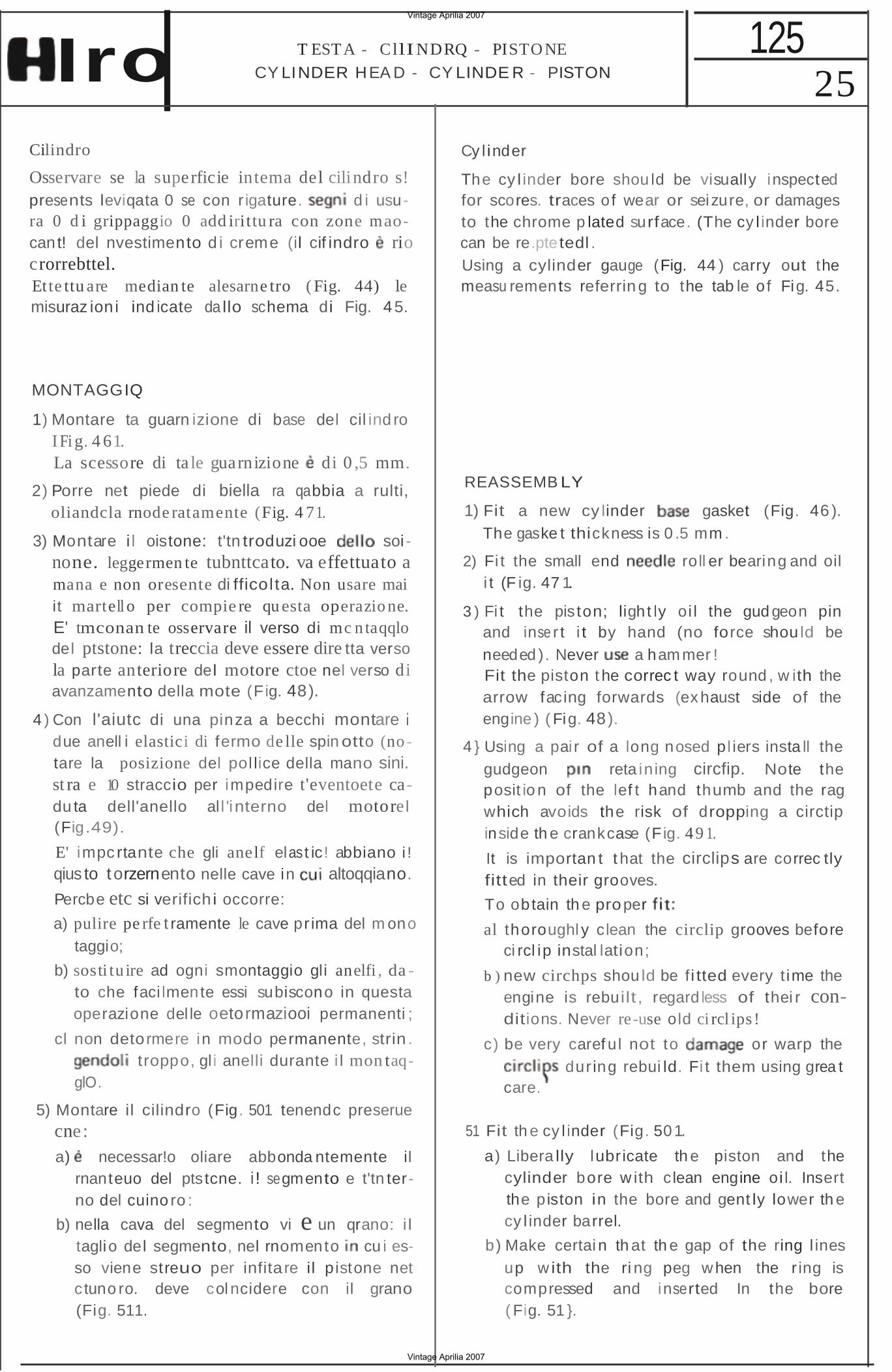
5) Montare il cilindro (Fig. 501 tenendc preserue cne: a) necessar!o oliare abbonda ntemente il
rnanteuo del pts tcne. i ! segmento e t'tn terno del cuino ro :
b) nella cava del segmento vi e un qrano: i l taglio del segmento, nel rnomento cu i esso viene streuo per infita re il p istone net c tuno ro. deve col ncidere con il grano (Fig. 511.
REASSEMB LY
1) Fit a new cy linder gasket (Fig. 46 ). The gaske t thickness is 0 .5 mm .
2) Fi t the small end roll er bearing and oil i t (F ig. 47 1.
3 ) Fi t the pis ton; ligh t ly oi l the gud geon pin and inse r t i t by hand (no force shou ld be needed ). Never a ham mer ! Fit the piston t he correc t way round , w ith the arrow facing forwards (ex haust side of the engine ) ( Fig. 48).
4 } Using a pai r of a long nosed pl iers insta ll the gudgeon reta in ing circfip. Note the posit io n of the lef t hand thumb and the rag which avoids the risk of dropping a circtip inside th e crankcase (F ig. 49 1.
It is importan t t hat the circlips are correc tly fitted in their grooves.
To obtain th e proper
al thoroughl y clean the circlip grooves before ci rcl ip instal lation;
b ) new circhps shou ld be f i tted every t ime the engine is rebuilt , regard less of thei r conditions. Never re-use old ci rcl ips !
c) be very caref ul not to or warp the dur ing rebui ld. Fi t them using grea t
care.
51 Fit th e cy l inder (Fig. 501.
a) Libera lly lubr icate th e piston and the cylinder bore w ith clean engine oi l. Insert the piston in the bore and gent ly lower th e cy l inder barrel.
b) Make certai n th at th e gap of the ring l ines up w ith the ri ng peg when the r ing is compressed and inserted In the bore ( Fig. 51 }.
Vintage Aprilia 2007
Vintage Aprilia 2007
26 125 TESTA - C l liNDRO PISTONE
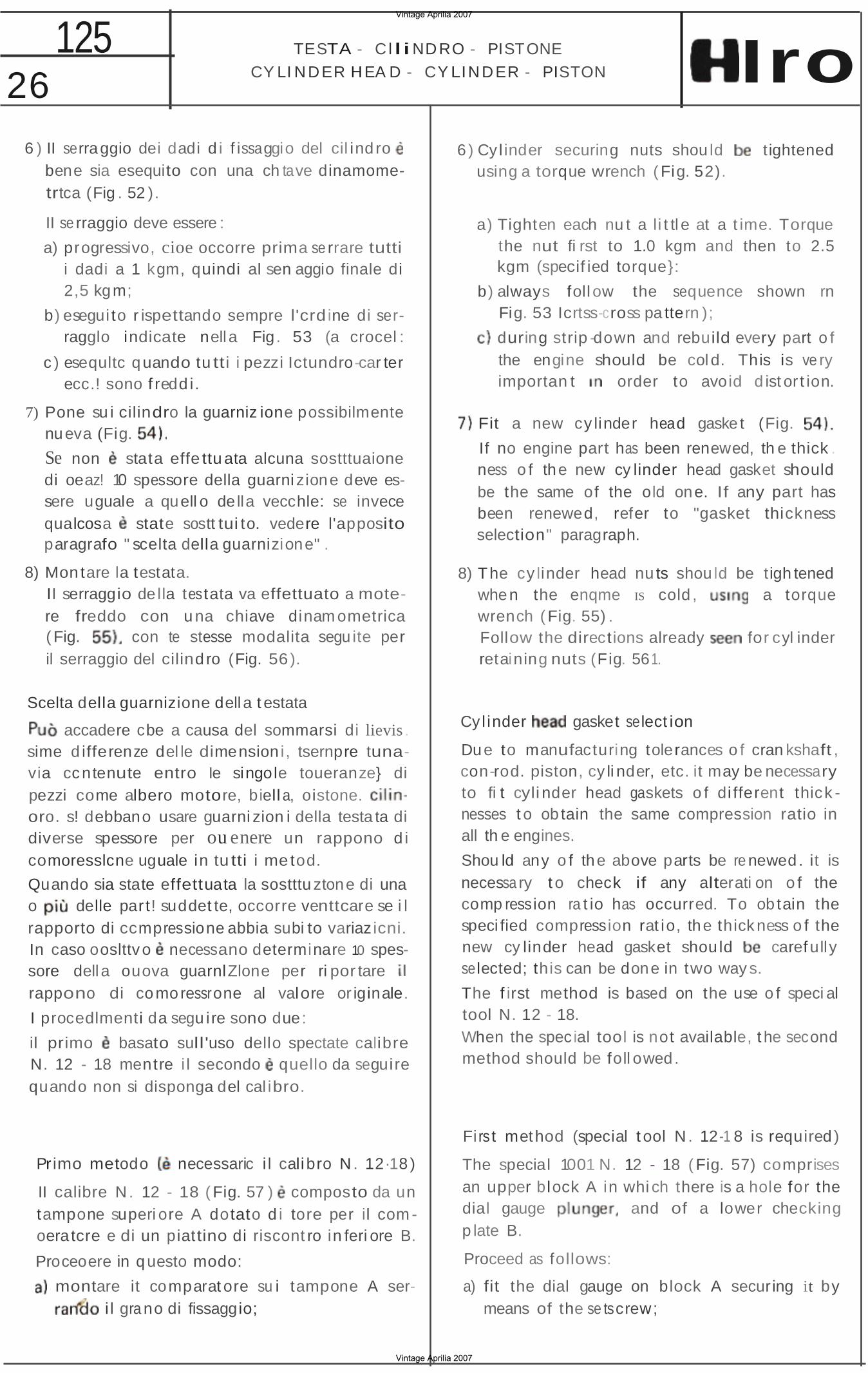
CY LI NDER HEA D CY LINDER PISTON Iro 6 ) II serraggio dei dadi d i f issaggio del cil ind ro
bene sia esequito con una ch tave dinamometrtca (Fig . 52 ).
II se rraggio deve essere :
a) progressivo, cioe occorre prima se rrare tutti i dadi a 1 kgm, quindi al sen aggio finale di 2,5 kgm;
b) esegui to r ispettando sempre l'crd ine di serragglo indicate nell a Fig . 53 (a crocel :
c ) esequltc quando tu tti i pezzi Ictundrocar ter ecc.! sono f redd i.
7) Pone su i cilindro la guarniz ione possibilmente nueva (Fig.
Se non stata effe ttu ata alcuna sostttuaione di oeaz! 10 spessore della guarni zione deve essere uguale a quell o de lla vecchle: se invece qualcosa state sostt tui to. vedere l'apposito paragrafo " scelta della guarnizione" .
6 ) Cy l inder securing nuts shou ld t ightened using a torque wrench ( Fig. 52).
a) Tighten each nu t a li t tl e at a t ime. Torque the nut fi rst to 1.0 kgm and then to 2.5 kgm (specif ied torque}:
b) always foll ow the sequence shown rn Fig. 53 Icrtss-cross pa ttern );
during strip -down and rebuild every part o f the engine should be cold. This is ve ry importan t order to avoid d ist or t ion.
Fit a new cy linder head gaske t (Fig.
If no engine part has been renewed, th e thick . ness o f the new cy linder head gasket should be the same of the old one. If any part has been renewed, refer to "gasket thickness selection" paragraph.
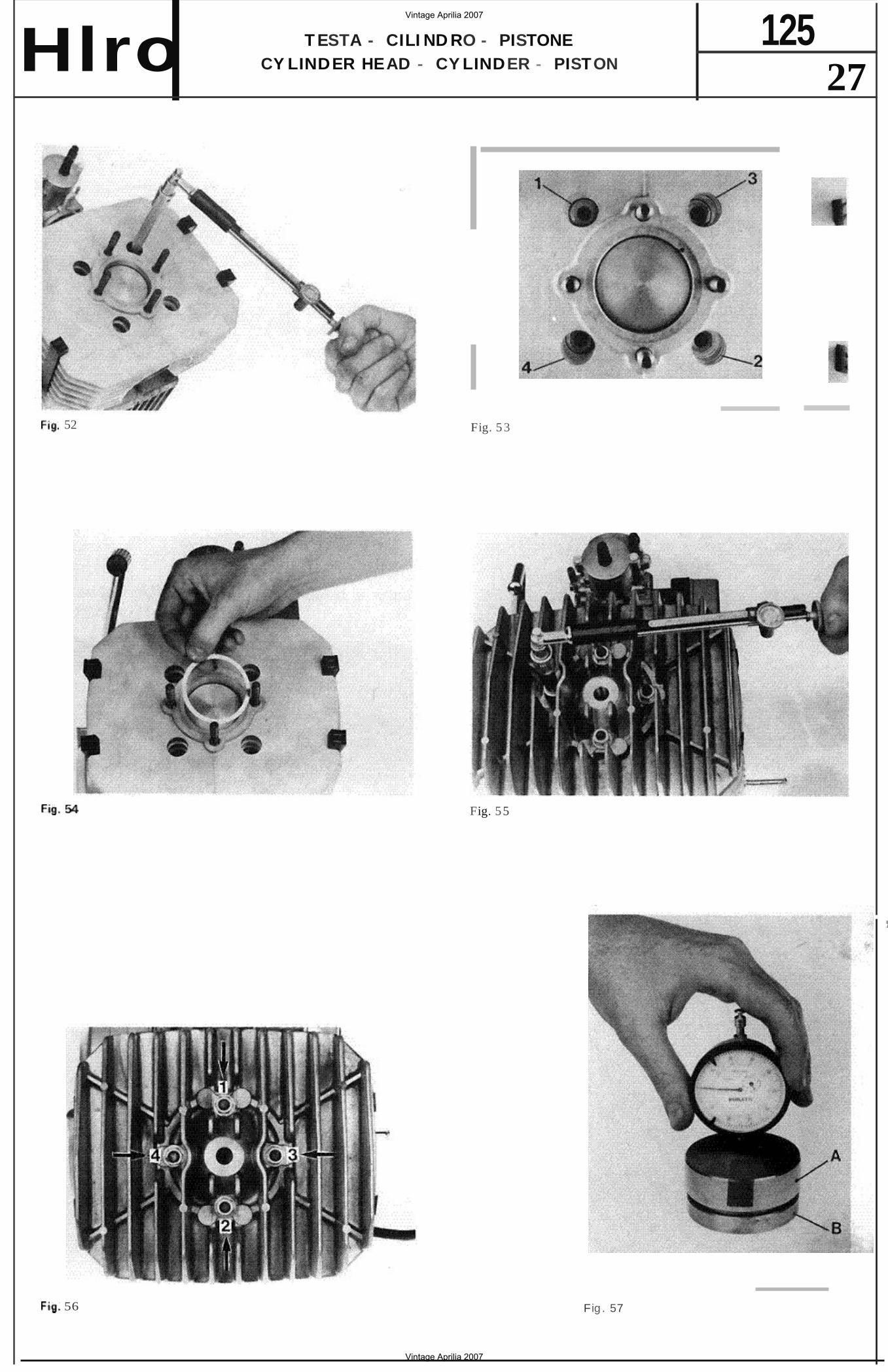
8) Mon tare la testata. II serraggio de lla testata va effettuato a motere freddo con u na chiave dinam ometrica ( Fig. con te stesse modalita segu ite per il serraggio del cilind ro (Fig. 56 ).
Scelta della guarnizione dell a t estata
accadere cbe a causa del sommarsi di lievis . sime d ifferenze del le dimension i, tsernpre tunavia ccntenute entro Ie singole toueranze} di pezzi come albero motore, biell a, oistone. oro. s! debbano usare guarni zion i della testa ta di diverse spessore per ou enere un rappono d i comoresslcne uguale in tu tti i me tod.
Quando sia state effettuata la sostttu ztone di una o delle par t! suddet te, occorre venttcare se i l rapporto di ccmpressione abbia subi to variaz icni. In caso ooslttvo necessano determinare 10 spessore dell a ouova guarnlZlone per ri por tare rappono di comoressrone al valore or iginale.
I procedlmenti da segu ire sono due:
il primo basato sull'uso dello spectate calibre N. 12 - 18 mentre i l secondo quello da seguire quando non si disponga del cal ibro.
Primo metodo necessaric i l calibro N . 12·18 )
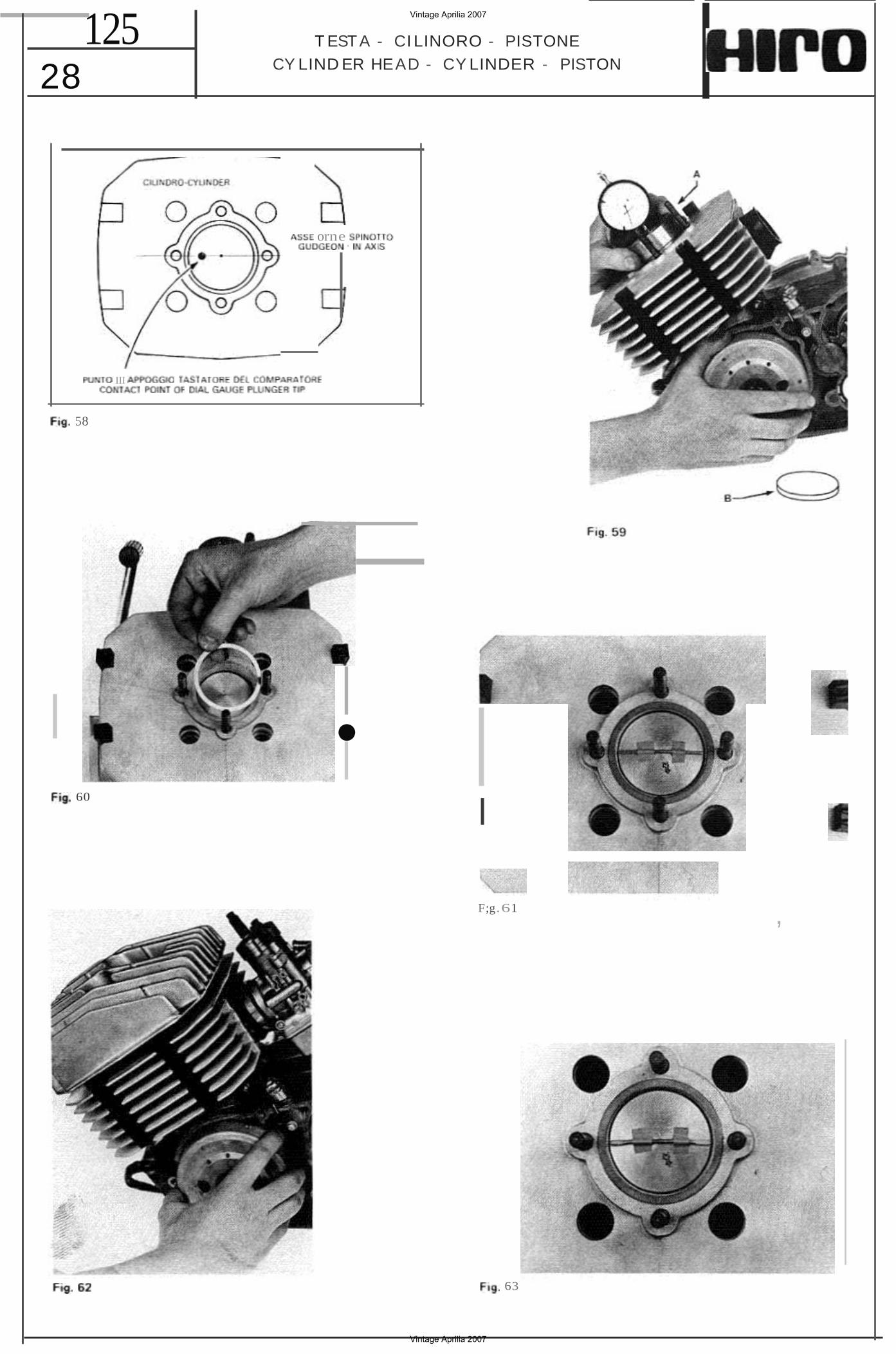
II calibre N . 12 - 18 ( Fig. 57 ) composto da un tampone superi ore A dotato d i tore per il com oera tcre e di un piattino di riscont ro in feri ore B.
Proceoere in questo modo:
montare it comparat ore su i tampone A seri l gra no di fissaggio;
8) The cy linder head nu ts shou ld be tigh tened when the enqme IS cold , a torque wrench ( Fig. 55) . Follow the directions already for cyl inder retaining nuts (Fig. 561.
Cy l inder gasket select ion
Due to manufacturing tolerances o f cran kshaft , conrod. piston, cy li nder, etc. it may be necessary to fi t cyli nder head gaskets o f di fferent thick nesses t o ob tain the same compression ratio in all th e engines.
Shou ld any o f the above parts be re newed. it is necessa ry t o check if any alterati on o f the comp ression ra t io has occurred. To ob tain the speci fied compression rat io, the thick ness o f the new cy linder head gasket shou ld carefully selected; this can be done in two way s.
The f irst method is based on the use o f speci al tool N. 12 - 18. When the special tool is not available, t he second method should be foll owed .
Fi rs t method (special t ool N . 12-1 8 is required )
The special 1001 N. 12 - 18 ( Fig. 57) comprises an upper block A in whi ch there is a hole for the dial gauge and of a lower checking p late B.
Proceed as follows:
a) fit the dial gauge on block A securing it by means of the se tscrew;
Vintage Aprilia 2007
Vintage Aprilia 2007
125T ESTA - CILI ND RO - PISTONECY LINDER HEAD - CY LINDER - PISTONHlro 27
52 Fig. 5 3
Fig. 55
,
56 Fig . 57
Vintage Aprilia 2007
Vintage Aprilia 2007
28 125 T ESTA - CI LINORO - PISTONE
CY LIND ER HEAD - CY LINDER - PISTON
III
orne '
58
• 60
l
F;g.61 ,
63
Vintage Aprilia 2007
Vintage Aprilia 2007
29 TESTA - CI LINDRO PISTONE 125
CY LINDER HE AD - CYLINDER - PISTON
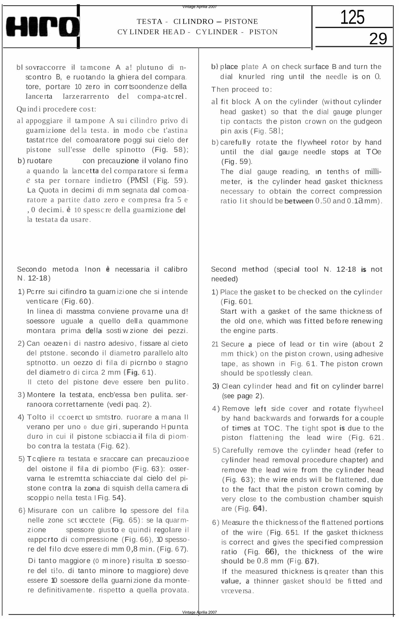
bl sovraccorre il tamcone A a! plu tuno di nscontro B, e ruo tando la ghiera del cornpara. tore, portare 10 ze ro in corr tsoondenze della Iance rta Iarzerarrento del compa-a tc rel .
Qu ind i procedere cos t:
a l appoggiare iI tampone A su i cilindro privo di guarnizione del la testa. in modo cbe t'astina tastat rtce del comoaratore poggi sui cielo der pis tone sull'esse delle spinotto (Fig. 58 );
b) ruotare a mana con precauzione i l volano f ino a quando Ia lance del cornpa ra tore si ferma e sta per tornare indie tro (PMSl (Fig. 59 ). La Quota in decim i di mm segnata dal com oaratore a partite datto zero e compresa fra 5 e , 0 decimi. 10 spessc re della guarnizionela testata da usare.
Secondo metoda l non necessaria i l cal ibro N . 12-18 )
1) Pc rre su i cifindro ta guarn izi one che si in tende ven tica re (Fig. 60 ). In l inea di rnasstma conviene provarne una d! soessore uguale a quello dell a quammone mon tara pr ima sosti w zione dei pezzi.
2) Can oeazen i d i nastro adesivo , f issare al cieto del ptstone. secondo i l diamet ro parallelo alto sptnotto. un oezzo di f ila di picrnbo 0 stagno del diametro d i ci rca 2 mm 6 1) . II cteto del pis tone deve essere ben pu lito .
3 ) Montere la test ata, encb'essa ben pulita. serranoora corret tarnente (vedi paq. 2).
4) Tolto i l cc oerct uo smtstro. ruorare a m ana II verano per uno 0 due giri , superando H punta duro in cui il pistone scbiacci a fi la di piom· bo con tra la testata (Fig. 62 ).
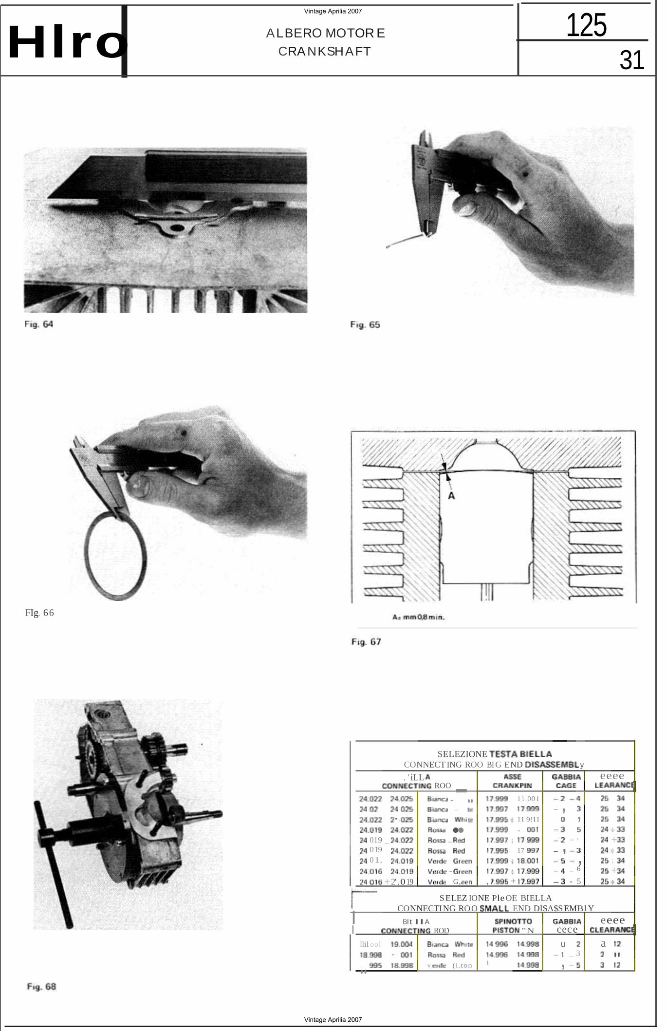
5) Tc qliere ra testata e sraccare can precauziooe del oistone il f il a di piombo (F ig. 63 ): osservarna Ie es t remt ta schiaccia te dal cielo del pistone con tra la di squish della camera scoppi o nella testa I Fig. 54}.
6} Misurare con un calibre spessore del f ila nelle zone sct uecctete (Fig. 65) : se la quarmzione e d spessore gius to e quind i regolare i l eappc r to di compressione (Fig. 66), 10 spessore del f i lo dcve essere di mm 0,8 min. (Fig. 6 7).
Di tant o maggiore (0 m inore) r isulta 10 soessore del ti!o. di tanto minore to maggiore) deve essere 10 soessore della guarni zione da montere definitivamente. rispetto a quella provata.
place plate A on check sur face B and turn the d ial knur led ring un til the needle is on O.
Then proceed to :
al f i t block A on the cyli nder (w i thout cyl inder head gaske t ) so that the dial gauge plunger t ip con tacts the piston crown on the gudgeon pin ax is ( Fig. 58l;
b) carefu ll y rota te the f lywheel rotor by hand until the d ial gauge needle stops at TOe (Fig . 59). The d ial gauge reading, tenths of rnillimeter, the cy l inder head gasket thickness necessary to obtain the correct compression rat io l i t shou ld be 0.50 and 0 .1amm).
Second method (special tool N. 12-18 not needed)
1) Place the gaske t to be ch ecked on the cyl inder (Fig. 60 1. Start w ith a gaske t of t he same thickness of the ol d one, which was f itted befo re renew ing the engine parts .
21 Secure piece of lead o r t in w ire (abou t 2 mm thick ) on the piston crown, using adhesive tape, as shown in Fig. 6 1. The piston crown should be spo tlessly cl ean.
Cl ean cy l inder head and fit on cy linder barrel (see page 2).
4 ) Remove side cover and rotate f lywheel by hand backwards and forwards f or a couple of at TOC. The t ight spot due to the piston f lattening the lead wire (Fi g. 6 21 .
5) Carefully remove the cy linde r head (refer to cy linder head removal procedure chapter) and remove the lead wi re from the cy li nder head ( Fig. 63 ); the w ire ends wi ll be f lattened, due t o t he fact that the piston crown com ing by very close t o the combustion chamber squish are ( Fig.
6 ) Measure the thickness of the fl attened portions of the wire ( Fig. 6 51. If the gasket th ickness is correct and gives the speci f ied compression rat io ( Fig. t he thickness of the wire should be 0.8 mm (F ig.
If the measured thickness is q reater t han t his thinner gasket shou ld be fi tted and
vrceversa .
Vintage Aprilia 2007
Vintage Aprilia 2007
125 ALBER Q MOTORECRANKSHAFT30
A LBERO MQTOAE
Smontaggio
1) Gli smo ntaggi prel iminari da cc m ple re secon do re ist ruzicn i impa rti te nei singoli capitof 501'10:
a ) testata , c ilind ro. pistone c he potrebbe subire da nneggiamen t i;
b) f r iziane at pun to 7 compreso d el capitala " Smo ntaggio tnaiooe ":
cl car ter e coron a della t rasmissione prima ria (vee! smontaggio parzia le della t rasmissione
orfrnerlal: d) alberc di comanoo del cambia con seu ore:
e) atbero oett'avviarrento con motte e innes to a de nti:
fl voteno complete di statore :
91pignone de lla t rasmissione ortmerte .
2) Separare i d ue carter come descrit to nei pun t! 2-3-4 del capi tola dedica te alia smon taggio del cambia.
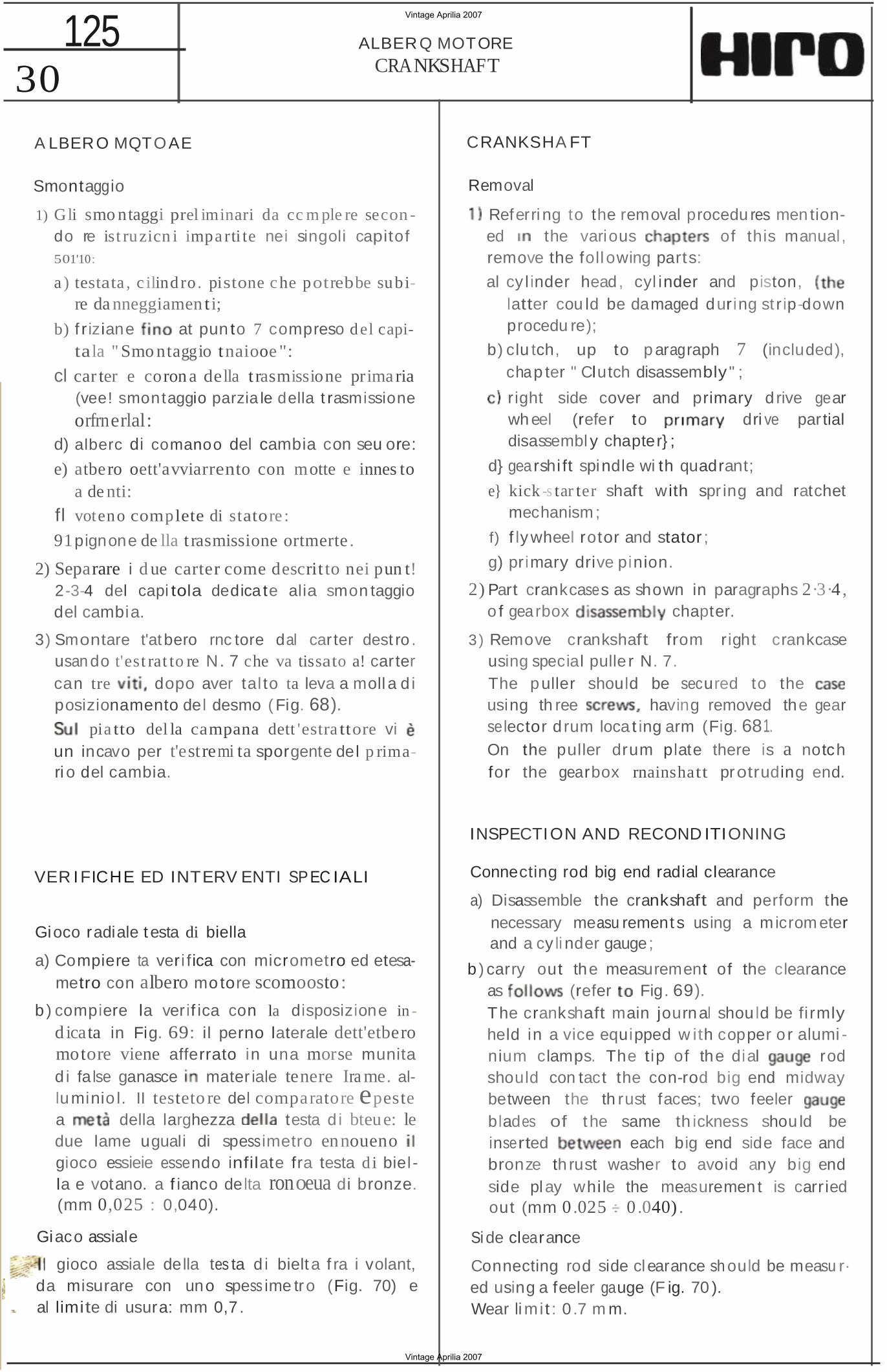
3) Smontare t'atbero rnc tore dal car ter dest ro . usan do t'est rat to re N. 7 che va tissato a! carter can tre dopo aver tal to ta leva a moll a d i posizionamento del desmo (Fig. 68).
pia tto del la campana dett 'estra ttore vi un incavo per t'est remi ta sporgente del p rimari o del cambia.
VER I FICHE ED INTERV ENTI SPEC IALI
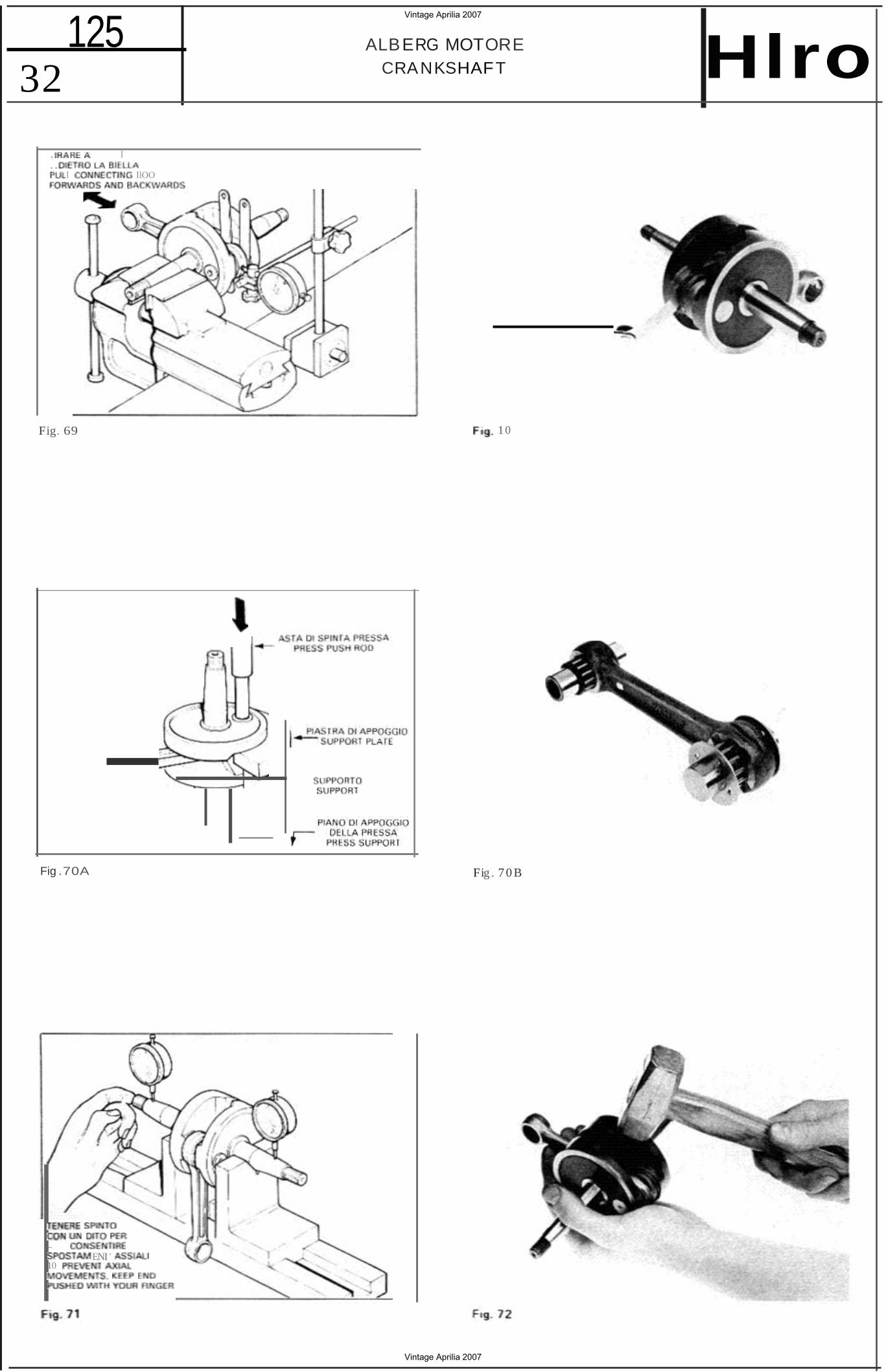
Gioco radiale t esta di biella
a) Compiere ta veri fica con micrometro ed etesametro con albero motore scomoosto:
b) compiere la verif ica con la disposizione in
d icata in Fig. 69: il perno laterale dett'etbero motore viene afferrato in una morse munita d i fa lse ganasce mater iale tenere Ira me. alluminio l. II testeto re del comparatore epeste a della larghezza testa d i bteue: le due lame uguali di spessimetro ennoueno gioco essieie essendo infilate fra testa d i biel la e votano. a f ianco delta ronoeua di bronze. (mm 0,025 : 0,040).
Giaco assiale
gioco assiale della tes ta d i bielt a f ra i volant, da misurare con uno spess ime tr o (Fig. 70) e al limite di usura: mm 0,7 .
CRANKSHA FT
Removal
Referri ng to the removal procedu res men tioned the various of this manual, remove the foll owing parts:
al cy l inder head, cyl inder and piston, latter cou ld be damaged during st r ip-down procedu re);
b) clu tch, up to p aragraph 7 (included), chap ter " Clutch disassembly " ;
r ight side cover and primary d rive gear wh eel (refer to dri ve partial disassembl y chapter} ;
d} gearshi ft spindle wi th quadrant;
e} kick -s tar ter shaft with spr ing and ratchet mechanism ;
f) f lywheel rotor and stator ;
g) primary drive pinion.
2) Part crankcases as shown in paragraphs 2·3·4 , o f gearbox chapter.
3 ) Remove crankshaft from right crankcase using special pulle r N. 7. The puller should be secured to the using th ree having removed the gear selector d rum loca t ing arm (Fig. 681. On the puller drum plate there is a notch for the gearbox rnainshatt protruding end.
INSPECTION AND RECOND ITIONING
Connecting rod big end radial clearance
a) Disassemble the crankshaft and perform the necessary measu rement s using a microm eter and a cy li nder gauge;
b ) carry out the measurement of the clearance as (refer Fig. 69). The crankshaft main journal shou ld be fi rmly held in a vice equipped w ith copper o r alumi nium clamps. The tip of the dial rod should con tact the con-rod big end midway between the th rust faces; two feeler blades of the same th ickness shou ld be inserted each big end side face and bronze th rust washer to avoid any big end side play whi le the measuremen t is carried out (mm 0.025 0 .040) .
Si de clearance
Connecting rod side clearance sh ould be measu r·ed using a feeler gauge (F ig. 70 ).Wear li m i t : 0 .7 m m.
Vintage Aprilia 2007
Vintage Aprilia 2007
31 125ALBERO MOTOR E
CRA NKSHAFTHlro
FIg. 66
SELEZIONE CONNECT ING ROO BI G END y
. ' iLL eeee ROO
--.. 11.00 1 _ ,
• . 11 9!11 , •• "
019 _ _ _ . +019 17 , 01. , ;
- _ 6 ++ 2'.019 G, , + - 5
S ELEZ IONE Ple OE BIELLA CONNECTING ROO END DISA$S EMBlY
I Bl t llA eeee I ROD "N cece
llil.ool u a " _ 3 " .. v (i.ton 1• . ,
Vintage Aprilia 2007
Vintage Aprilia 2007
125 32
ALBERG MOTORE CRANKSHAFT Hlro
, v. l ..
l IlOO
Fig. 69 1 0
Fig .70A Fig . 7 0 B
_ ENI '
10
Vintage Aprilia 2007
Vintage Aprilia 2007
33 125A LBE RO MOTORE
CRANKSHAFTHlro Scomposizione e albero motore
L'atberc motore in tre pezzi: i due votaoi e t'asse di accooptemento umn per piantaggio con lnterterenza. Montaggio e scomposlzlone awengono median te pressa idraulica a bil anciere: ta forza ricbiesta
di circa 5 t onn.
pi antaggio e 10 sflt emento dell'asse vengono eseguiti in un volano per volta ; du rante queste ooerazloni 11 votano in ques tione viene appoqqieto su un supporto adatto.
Prima del montaggio necessaria tubriflcere i f ori de i volent con sego e la gabbia a ru ll i della testa di bietla . con qrasso. Dope i l mootaggio I'albero motore va cenrrato.
Centretura albero motore
Med iante due stret ti support i a V e com paratore. ve rifieare i l cent raggio detl'atbero Ioccorre impedire quelsiasl spostamento den'albero entre i su pporti in senso assl ele pe r non falsare la misura, essenc e il testatore del comparatore poggiato su una su pe rficie conica (Fig. 71 I. In un giro la max eccentriclta misurata agli es t re rni del coni tateraf deve essere: mm 0,010.
L'escursione max della tancen e del comparators . che marca il doppio dett'eccentrtci ta, deve essere : mm 0,020.
La raddrizzatura va tatta con colpi di mazzuolo d i rame 0 con un cu neo che agisca fr a i vo!ani
Montaggio
1) Montare i cuscinetti e oaraotio con te stesse modatita sequlte al punt! 1·2 capitolo rete tlvo al montaggio de l cambio.
I cusci net t i a sfera se ne in esecuzto ne C3 (gio · co maggiorato l ; fare a t tenzione alia ron dell a che va conocata so t to il cuscine tto rnotore. allog9iato nel ca r te r destro ( Fig. 74 ). Nei pa raolio a doppio labbro il vane esiste nte fra i due labbri va riem pito con grasso a! silicone.
Crankshaft d isassembly and reassembly
The cran kshaft is bui lt up f rom three parts ; the c rank pin is an in te rfe rence fi t w it h the holes in the flywhee ls.
Cra nkshaft disassembly and reassembly should be ca rried ou t by means of an arbor or an hydrauli c press ; the required force IS abou t 5 tons.
The c rankshaft sh oul d be properly supported and the crankp in shou ld be pressed out from one flywheel at a time (this applies a lso to the crankpin refitting procedure) .
It is necessary to lubricate the flywheel holes wi th t all o w and the big end bearing with grease befo re asse mbly . After reassembl in g should be the c rankshaft caref ully al igned .
Crankshaft alignment
Check crankshaft a lignment using two narrow vee.blocks and a d ia l gauge. The t ip of the di al gauge stem contacts a tapered su rface; for th is reason any axial movement o f the cranksha ft should be avoided , to ca rry out a correct measurement (Fig. 71).
Rotate the cran kshaft one com plete turn : the run out measured a t the e nd of the should not exceed 0.0 10 m m.
Note t ha t the di a l gauge reads t he double of the c ran kshaft runout va lue , the refore th e dial gauge reading should not exceed 0 .020 mm .
The crankshaft should be a ligned using a coppe r mallet or a wooden wedge inserted between the flywheels ( Fig. 72).
Reassembly
1) The main bearings and the seals shou ld be fitted fo ll owi ng the procedure shown par agr aphs 1-2 (bearing replacement), gearbox chapte r.
The ball bearings used in this engine are of C3 (loose c learance ) class. A washe r should be fitted beneath the righ t mai n bearing ( Fig. 74) . The vane between t he two of the oil seals should be filled with sil icone grease .
Vintage Aprilia 2007
Vintage Aprilia 2007
34 125 A LBERO MOTO RE
CRANKSHAFT
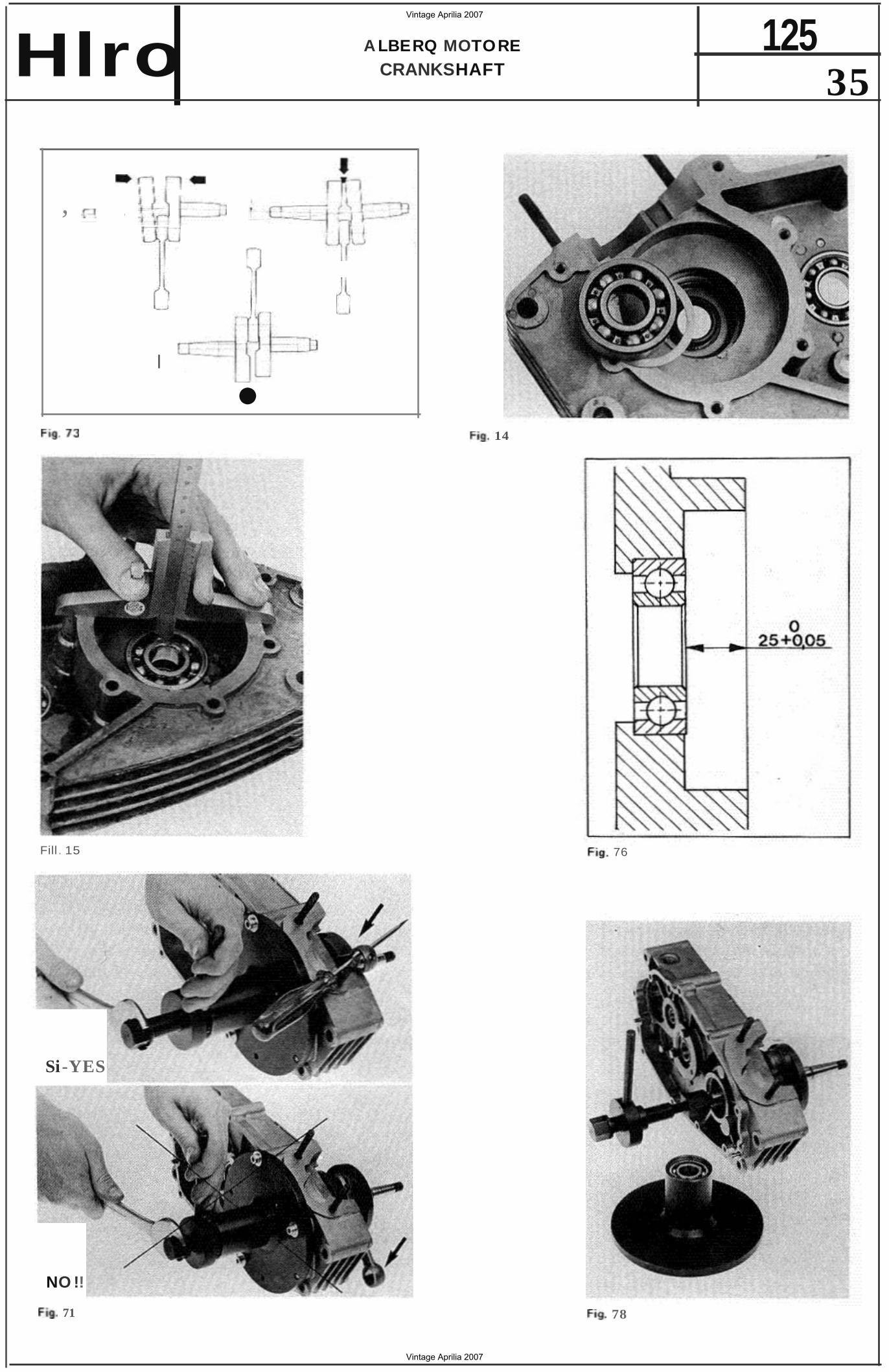
2) Misurare con un cafibro di prc fondi ta la distanza dall'anell o in terne del cuscinet to delI' imbiellaggio al piano di giunzione del carter
ambedue i carter) (Fig. La distenza deve essere per e ntrambi i carter:
o mm 25
+ 0,05
3) Mon tare t'ajbero moto re nel carter destro:
a] se disponibile un forn o a circotaziooe di ana cetda. scaldare il carte r compteto di cuscjnerti. in modo uni forme a 80° C (in questa caso non essere indlspensebile t'art rezzo N. 2).
b) dopa averio leggermente lubri ticato con sago 0 grasso , in fi lare i l perno laterale dell'albero motore nel cusctnetto: i l perno laterale in questione que ue con cono corte {d i accopplarren tc con picnone]:
cl collegare. mediante I'apoost to dado. la f i let tatura del perno dell'albero motore con la vite dell'attrezzo N. 2 (Fig. 771 (nella Fig. 78 per chiarezza la campana deu'att rezzo stata tor te}:
d ) tissare can viti i! oia tto del la campa na al carte r;
e) tenendo ferma la vite can una chieve. ru e tare te dell'attrezzo fino a Quando il pern o tate rafe dell' imb iel laggio non si in fi lato comp le tamente ne! cusclnet to.
Attenzione : importan tissi mo, per non dan neggiare la b ie lla , che esse. du rante il montaggio , non trovt ma i a forzare contra il carte r rna che essa venga ten uta corrispondenza delta Ieritcia di passaqqto
blelta stessa, esistente net carter alta base del cilind ro.
4 ) Completare il rnon taggio del carte r come descrit to ai punti 11· 12·13 del capi tole dedica to al montaggio del camb io .
2 ) Measure the distance between main bearing mner and crankcase mating surface, using a micrometer depth gauge . This should be done fo r bo th crankcase halves (Fig. 75).
The d istance for both cran kcases must be :
o mm 25 + 0,05
3 ) Ins tall the crankshaft in the right cran kcase:
al a hot air circula tion ove n is available , evenly heat the crankcase comple te with bea rings to 80° C. th is case speci al
N. 2 is unnecessary);
bl lightly lubricate the puuon shaft with tallow or grease and insert it in to the main bearing; the pinion shaft is the one with the
tape r (primary drive side);
cl using the proper nut secure the sha ft thread to the screw of special too l N. 2 (Fig. 77) Fig. 78 the tool drum has been removed for clari ty) ;
d1secu re the drum plate to the crankcase by means of screws;
e ) ho ld the special tool sc rew s teady using a span ner, and turn the hand le of the tool until the pinion shaf t is p roperl y fitted in the ma in bearing.
Warn ing: to avoid damage to the connect ing rod, be very carefu l du ring the above operation and maintain the con-rod correct ly a ligned with the cran kcase openmq through wh ich it sh ou ld pass.
4) Co mp le te crankcase reassemb ly as desc ri bed In paragraphs 11-1 2-13, gearbox rebu ild chapter.
Vintage Aprilia 2007
Vintage Aprilia 2007
35 125A LBERQ MOTORE
CRANKSHAFTHlro
,
I
• 14
Fill . 15 76
78
Si-YES
NO !!
71
Vintage Aprilia 2007
Vintage Aprilia 2007
125 36
FR IZ IQNE CLUTC H
Fig_79
F ill . 8 1
Fig. 83
Fig. 8 2
o o
Fiy . 84
Vintage Aprilia 2007
Vintage Aprilia 2007
37 125FRIZI QNE
CLUTCH
FRIZI ONE - S MO NTAGG IO
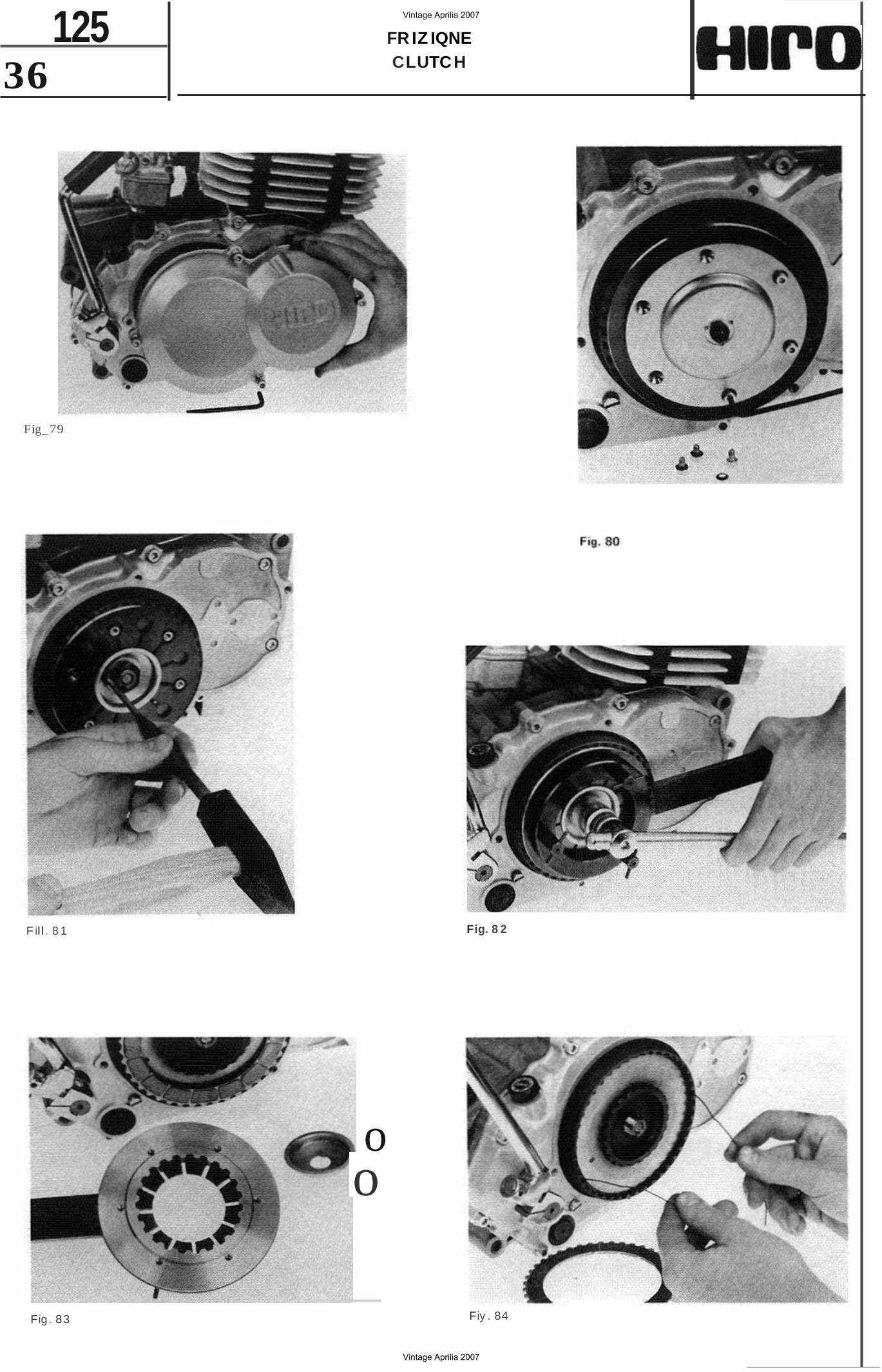
1) Togliere i l coperch io della t rizione peste suttato des tro del rnotore (Fi g.
2) Svita re Ie sei vit i a bru gola del platte spingid ischi tacendo attenzione a recuperare te ronde lie dentate (Fig. SOl.
3) Servenoos! di un cacctasotne 0 di un piccolo scetpetlo . raddrizzare la rondella di sicurezza del dado ce nt ra le (Fig. 81l .
4 ) Con una chiave da 22 mm svitare il dado centrale a tile t tatura des tra (Fig. 82 ), La tdzlone va immobil izzata con t'apposito attrezza N. 9 dotato di t re vit i a ga lle tto da avvitare tre dei sei fo ri f ilettat i eststen t i su i d isco terminate .
5) Svita to il dado centrale possibile srnon tare la ronoelte d i sicurezze. 10 scodettin o di rite900 de ll a mo ll a e la mol!a stessa insieme con i l disco terminale e J'attrezzo N. 9 (Fi g. 83). (Fig. 83).
61lnclinando i l motore a usando due gancetti di t il di ferro, far uscire dischi della carnpa. na (F ig.
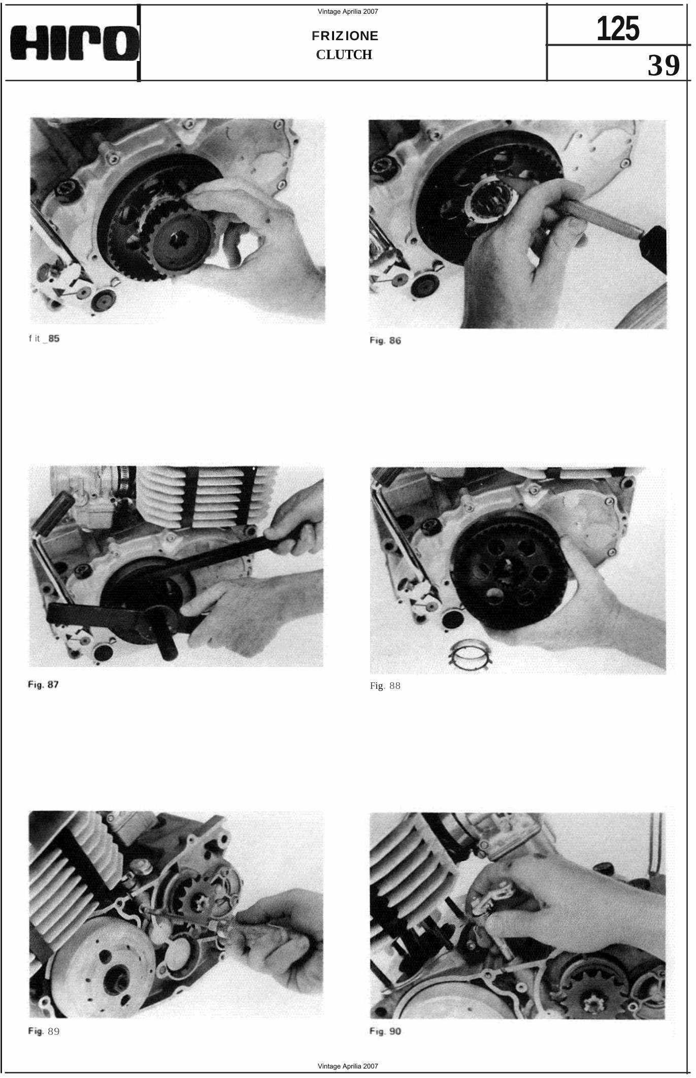
7) Smon tare il mozzo del la fr izione tlrandoto a mana t'estemo (Fig. 85).
8) Con un piccolo scalpello raddri zzare i l dente dell a rondef!a di srcu rezza dell a ghiera di bloccaggio della campana 86 ).
9) Svitare la di bl occaggio della campana della tr tztone. a titet ta tu ra dest ra (Fig. 87) .
Gl i attrezzi da usare sono: la chiave N. 10 dotata di dentatu ra per i l bloccaggio della campana e ta chiave a denti f ron tal! N. 8 per svitare ra ghiera. Per renoeme sicuro t'uso, ta chiave a dent i Irontaf N, 8 e dotata di un perno di cent raqgio cbe si impegna nell a parte spc rqente delI'albe rino.
10) Tlrandote a mano l 'estemo. smon tare la campana fr izione (Fig.
") Per srn ontare il clsoostt tvo di comando della tnzt one. occorre toqliere i l coperchio si nistro e svitare ccmptetemente la vite di ritegno della leva di comando (Fig.
Nota : 10 smon taggio del dispositive di comando dell a frizione e indipendente dall o smon taggio d i eltre pa r ti del la f r izione.
12) Tirandola verso t'e tto possibile smontare la leva di coma ndo; necessaria perc aver prevenrivarrente t alt o Ia testata e alzato il ci-
CLUTCH · DISASSEMBL Y
1) Remove the clutch cover, which is located on engine right side (Fig. 79 ).
2) Undo the si x Allen screws from the pressure p late, taki ng care not to lose the toothed washers 801 .
3) Bend back the central nut lock ing tab washer using a ch isel or a drift (Fig. 8 1).
4) Loosen the central nut USing a 22 mm spanner (r ight hand th read) (Fig. 82). The clu tch hub should be held by means of special tool N. 9 . Th e three winged screws of th e tool should be screwed th ree of the six threaded holes of the end d isc.
5) Having unscrewed the cent ral nu t , remove the lockwesher, the spri ng retaining collar and the spring with the end d isc and special tool N. 9 ( Fig. 83 ).
6) the engine sideways or use two hooked wires to remove the clu tch discs from the drum (Fig. 84 l.
7) Remove the clutch hub i t out by hand (F ig. 85).
8) With a small chisel f latten the tab of the lock ing washer of the drum securing r ing nut (F ig. 86) .
9) Undo the clutch d rum retaining r ing nut (righ t hand thread) (Fig.
For this operation use special t ools N. 10 (c lutch dru m holding tool) and N. 8 (peg spanned.
To ensure a proper use of the peg spanner [ N. there is an align ment pin which f its on the protru ding portion of the shaft.
10) Remove the clutch d rum pu ll ing it ou t by hand ( Fig. 881.
' 1) To remove the clu tch release mechanism necessary t o tak e left engine cover off and
to completely loosen the gear shift lever retaining screw (Fig. 89 ).
Note: t he clu tch release mechanism can be removed independently w i thou t dismantling the other parts of t he clutch assembly.
12) The clutch mechan ism operating lever can be removed pull ing i t upwards; it is necessa ry however t o remove the cy linder head and t o l ift up barrel a f ew inches (without removing
Vintage Aprilia 2007
Vintage Aprilia 2007
38 125 FRIZIONE
CLUTC H Hlro lindrc d i qualche centimetre senza sfilar tc dal pistone.
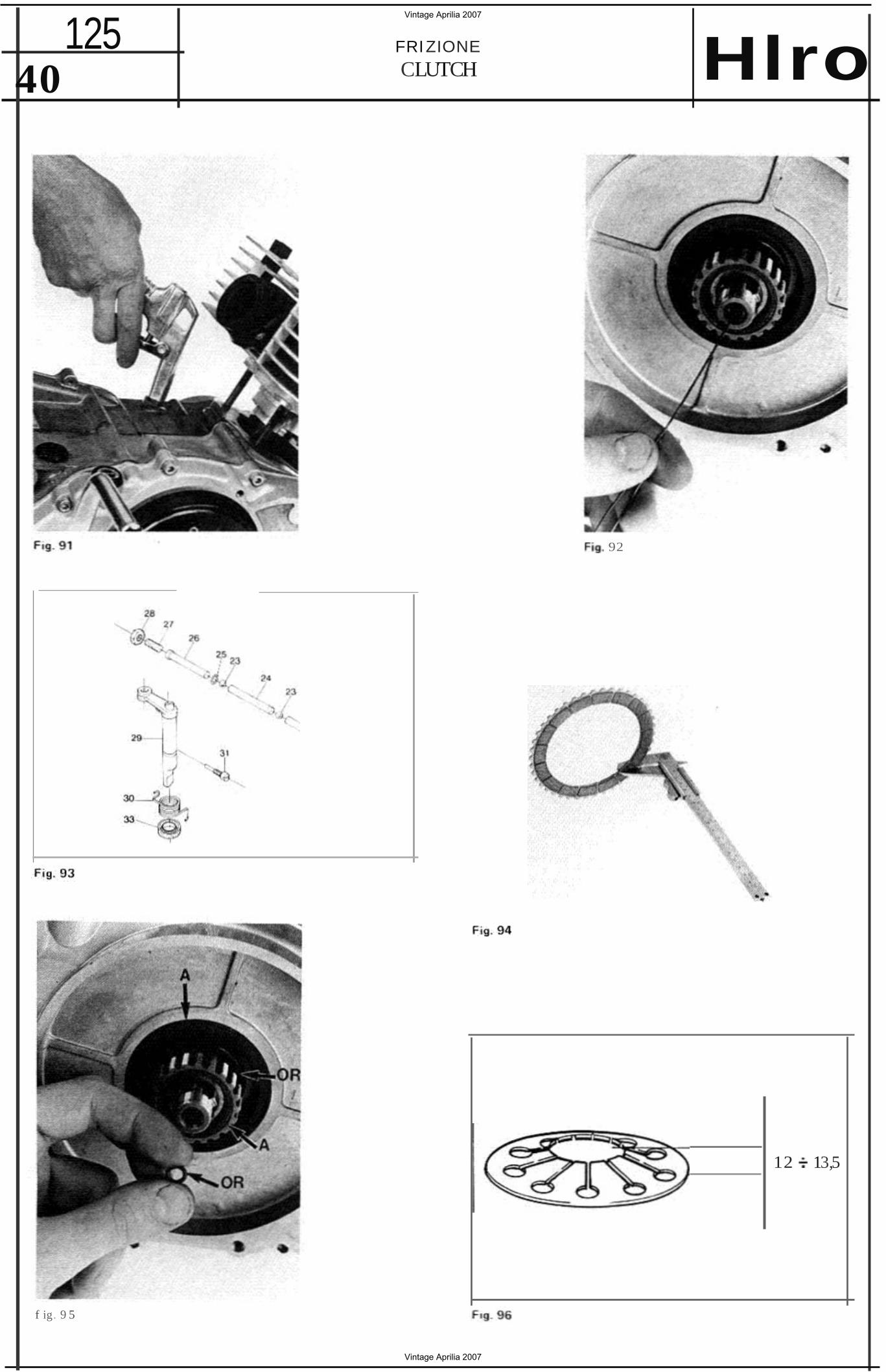
13) Per far fu oriuscire le asti ne di camanda della frizicne immettere ar ia compressa dal fo ro del la leva (Fig. Successivarrente, se necessaria. t irare fuori con un piccolo gancia di ti l d i ferro i l minuscolo OR alloqqia to nel foro dell'alberino (Fig. 92).
VERI FICHE
1) Osservere 10 state dentatur a dell a campana e del mozzo-trtz tone: protondi segni di usura possono impedire un regolare distacco dei
2 ) Osse rvere 10 state superficiale dei dischi me terlici che non devono esse re detorma tl . rigati 0 con d l su rriscaldamen to.
3) Osservere 10 state superf iciale del dischi guarniti : it ma te riale di art-ito deve esse re integra. non vetrificato 0 con profonde riqatu re 0 con sum. anormali ; verificare con un calibre 10 spessore (Fig. 94) :
spessore disco guarn i to da nuevo : mm 3,5 0 ,05.soesso re mi ni mo al l im ite di usura: mm 3,2.
4 ) Se sui disch i e nella campana si notassero treeee d i o lio oceorre veri f icare Ie ccndiz ioni dei due paraolio (A) e dei due OR (Fig. 951
5) Nei component ! dispositive di comando del la fr izione non si devono notare segni d i usura o surr iscaldamento. Occorre a tale scope osservare la parte atti va della leva di eomando e t'estremita piana dell'asti na su cui essa tavora, le estrerra ta delle ast ine che lavorano contrc la sfera e cen tro il registro a vite , ed anehe naturalmente quest i uttiml due corrconenti.
61 11 velo re campana tura dell a motte a d ia . framma (Fig. 96) deve essere:
a) a mona libera mm 12 til prima valore relative alia mo lla nu ova ment-e il secondo i l minimo amrnessol :
b ) a mo l la mon tara mm 1 -. 2 ( in questo caso la campanatura regolabi le tramlte rande lle di diverse spessore . vedi rncntaqqio) .
the pi ston f rom the bore), before the lever can be withdrawn.
13) To remove clutch pushrods, app ly a of compressed air to the lever hole (Fig. 91) . If necessary remove , wi th a hooked wire, the a ·r ing housed inside the sha ft hole (Fig. 92).
INSPECTIONS
1) The slots in t he clutch drum and in the hub shou ld show no wear grooves (which may cause the plates to drag).
2) Visually inspect t he steel plates, which shou ld be in good condi tion , wi th no grooves, warpage or si gns of overheating.
3) Check the f r iction plates surface; there should be no grooves, abnormal wear, glazing or any k ind o f damage. Meas ure fr icti on p lates thickness (Fig. 94) : standard value : 0.05 mm min. value l imi t : 3.2 m m }.
4 ) Should an y t race of oi l be detected on the plates or inside the drum, check the two oi l seals (A ) and the two Q·rings f or damage or wear (Fig. 95).
5) No traces of overheat ing or of wear should be not iceable in t he clu tch release mechanism . Carefully examine the opera ting lever work ing surface, the flattened end of the rod on whi ch the lever operates, the pushrod ends, the steel
and the adjusting screw.
6 ) The diaphragm spri ng bow shou ld be (Fig. 96) :
a) unmoun ted bow : 13,5 mm (new spring) min. 12 mm (wear lim it );
b) fi tted spring bow: 1 2 mm spring bow can be adjusted usmq
shims of various thi cknesses; refer to clu tch rebuild ].
Vintage Aprilia 2007
Vintage Aprilia 2007
39 FRIZ IONE 125 CLUTCH
f it _
Fig. 88
89
Vintage Aprilia 2007
Vintage Aprilia 2007
125 FRIZIONE
CLUTCH Hlro40
92
12 13,5
f ig. 9 5
Vintage Aprilia 2007
Vintage Aprilia 2007
Hlro FRI ZI ONE CLUTCH
125 41
1-_.__._ ...
97 Fig . 98
99
10 1 r 'lI . 102
Vintage Aprilia 2007
Vintage Aprilia 2007
42 125 FRIZ ION E
CLUTCH
FIg. 10 4
j ! !
105
, 10 6 Fo g. 101
Vintage Aprilia 2007
Vintage Aprilia 2007
Hlro FRIZIONE CLUTC H
125 43
MONTAGGIQ FR IZIONE CL UT CH REBUILD
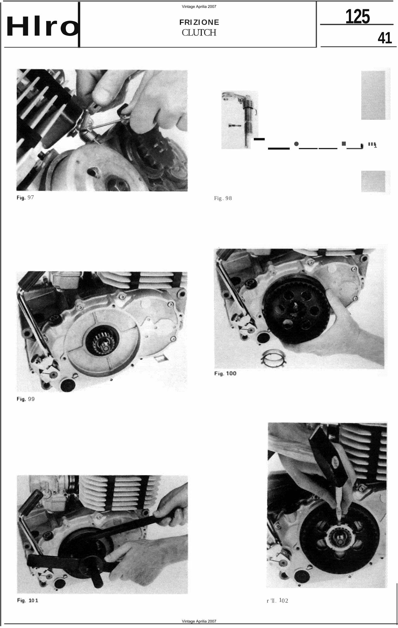
1) Inf i lare a tendo Ia leva di comando. quindi Inser t the operat ing lever f ull y home and, usanc e un piccolo cacciavite come leva, ag" using a small screwdriver, hoo k the top end qancia re t'es t remc supe rio re de lla mona alia of the sp ri ng t o the lever (Fig. 97). leva (Fig_9 71. The lever pivot and its cam-shaped end II pemc della leva e la sua esuemita a camma shou ld be lubricated before refitt ing. devono essere Iubrificati prim a del moo 2) T ighten the retaining screw. 1a99iO.
3) Lubrica te the th ree pushrods, t he two steel 2) Avvltare a fondo la vi le di r itegno. ba ll s and the a ' ri ng and insert t hem in the 3l ln fi la re ne t fo ro dell'a lbero , tu t te ben clia te , shaft hole. t he order shown
Ie tre astine. te due sferette e I'OR nett 'ordi Fig. 98. The flat end of t he p ushrod should ne indicato in Fig. 98 It'est remrta piana be fi tted towards the cam-shaped end o f the I'astlna va con t ra t'est remita a camma della ope rat ing lever. leva di comandol . Before install ing the end pushrod and the Prima d i in li lare t'astt na te rm inate e I'O R, O·ring, t urn the on i ts side and con i t motore dis post o o rlzzo ntatmente . far lubricate t he shaft hole wi th a few drops of cadere net f oro dett'atbertno poc he gocce di oil ( Fig. 99 ). olio lubrifican te (Fig. 4 ) Ligh t ly lubricate the oil seal l ip w ith clean
4 l Dope ave r leggermente oliato il la bbro del enqme oi l and refi t the clu tch drum peraoltc rnon tare la campana (Fig. 100). (Fig. 100).
5 ) Mon tare la rondella d i sicurezza e la ghiera. 5) Install locking t ab washe r and r ing nut . II serraggi o della ghiera va tettc can Ie chiavi The r ing nut shou ld be tigh tened using spec iali N. 8 e N. 10 con le stesse modatna speci al tools N . 8 and N. 10 (refer to clu tch dello smant aggio ( Fig. 10 1) . d ismant l ing paragraph) ( Fig. 101).
Dop o il serraggio , con un leggero colpo di 6 ) Havin g t ightened the nut, bend a martello e un cecclesptne. spingere pi egando· lockwasher tab in to a ring nut slot using a to. un dente della rondette di stcurezza entre punch and a mal let ( Fig. 102). un in tagl io delta ghiera (Fig. 102).
7) Install the clu tch hub on the splined port ion 7) Mantare i l mozzo della f rizione sull'estrem i of the shaft (Fig. 103 ).
scenetata deu'at bero (Fig. 103).
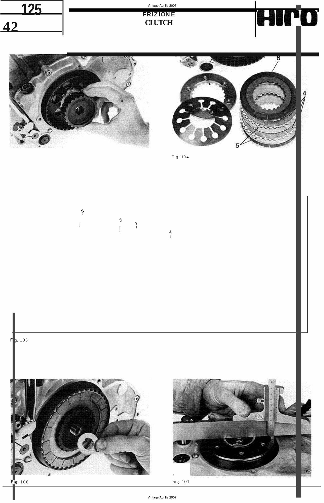
Montare di schi nell'o rdine indicate netle Figg. 104 e 105 : vi sona tre dischi quat . niti da ent rambe te pa rti, due dischi lise! IS} ed un disco (6 ) guarn i to da una sola par te che va appoggiata centro il f ondo della cam.
8 ) Insta ll t he clutch pl ates f oll owing the sequence shown in Fig. 104 and 105. There are t hree pl ates which are l ined on both sides, t wo steel p lates (5 ) and a pl ate which has only one side l ined and that shou ld be placed against the d rum bottom.
pana.
9 ) Montare la rondella di spessorazione 32 9) Fit shim N. 32 ( Fig. 106 ).
(Fig. 106). Th is shim adju sts the cl utch spnnq bow;
Med iante questa rondella, disponi bile in di · i t available in various t hi cknesses.
verst spesson. si regala la ca m panatura della To c heck and select the correct sh im,
molla a diaf ram ma; per effettuare i l cont rol proceed as f ol lows: 10 e la scer ta della soessore occorre:
, al fi t the shim t o be checked and carry out a) m onta re la rondel la da vertftcere e prosequi
the rebuild up to step 13 nut should re il montaggia f ino al punta 13 serrando be t igh tened f ully ); regalarmente il dado;
b) d isporre diamet ralmente su l lo scodellino b) pl ace a precision ground bar on a st raight una sba rre tta retti f icata ad una squadra di edge on the spring coll ar. as shown in orecistone. q uindi con un calib re di oro Fig. 107. Using a dep th gauge or a vern ier t ondi ta od anche un calibre no-mate effe t · cal iper, carry a measuremen t on the tuare come indicate in Fig. 10 7 due misu collar edge and another on the sprt ng raztcm: una sui bordo della scodetnno.
Vintage Aprilia 2007
Vintage Aprilia 2007
44 125 FRIZI ONE
CLUTCH Iro t'eh re sui bordo del la motte :
cl il valcre della campanatura data dalla d ifferenza fra te due misure: oeve essere di mm 1 2;
d l se non 10 tosse occorre vartere 10 spessore della ronde lla 32. tenendo presente che di tanto au rrenre (0 diminuiscel questo spessore, di tanto aumen ta (0 d iminuisce l il valare della campaoa tura.
10) Mon tare il disco terminate e la motte dope averli apoticati. con Ie t re vit i a galletto, et l'a t t rezzo N. 9 (Fig. 108).
11) Mcn tare 10 scode llino di ritegn o della molla (F;g. 1091.
12) Prima di montara la rondella di stcurezza del dado cent rale, piegarne leggermente un lembe per facil itare la successrva rip iegatura ( Fig. 11OJ. E' bene usare una rondella nueva ad ogo i mont3ggio; se pe rc fosse usare la vecchia , occorre ripiegarla in un punta diverso .
13 ) Serrare a 9 kgm il dado cen trale con una ch! ave dinamometrica IFig. 111 ); la viene immobilizzata ca n t'attrezzc N. 9 usato per il mon taggio de lla moue .
14) Accostandola bene ad una taccia del dado. la rondella d i sicu rezza usufruendo
del lembo rialzato in precedenza (Fig. 112).
15) II p iatto spingi dischi va fi ssato al disco termt nale can set a bru qola d otate di rondelle den tate di sicurezza (Fig. 11 3 ).
16 ) Agi re su i registro a vite de l piatto in modo da tesctere una corsa a vuotc della leva di comando sui motore di 3 5 mm (Fig. 114 ).
Questa reqistrazione va rtoetu ta . con Ie stesse modatita. durante I'uso dopa due volte che si registra il gioco della leva della frizione al manubria (Fig. 115).
the bow is the d iffe rence be tween the two measurements.
bow: 1 2 mm;
d ) if the measured bow does not co incide with the speci fied value. the th ickness of shim N. 32 should be modif ied. The bow increases (or decreases) of the same amount of the shim 32 inc rease (or decrease) .
10) Secu re the end plate and the spring to special tool N. 9 by means of th ree winged screws. and fit them home (Fig. 108).
11) Fit the spring retaining colla r
12 ) Slightly bend one side of the tockw asher order to ease final bend ing) before fitt ing it on the shaft (Fig. 110 ). Every time the reassembled IS
strongly advisab le to fit a new lockwasher. Should however an old one be used . bend it on a diffe rent side .
131Tigh ten central nut to 9 kgm usi ng a torque wrench (Fig. 111 ); the clutch should be held
by mea ns of special tool N. 9 (already used for spring refitting).
14 ) Raise the side of the tab washer tha t slightly bent before hand (step 12) and forced it one flat of the hex nut (Fig. 11 2).
15) The pressure plate should be secured to the end disc using six Allen screws with tooth tockweshers (Fig. 113 ),
16) The clutch operating lever fitt ed on the crankcase shou ld have 3 5 mm free t ravel. This shou ld be ob ta ined by means of the adjusting screw fitted to the plate (Fig. 114). When using your mo torbyke remember to perfo rm th is adjustmen t every other time the handlebar lever ad juster is used to set the clu tch cable play (Fig. 1151.
Vintage Aprilia 2007
Vintage Aprilia 2007
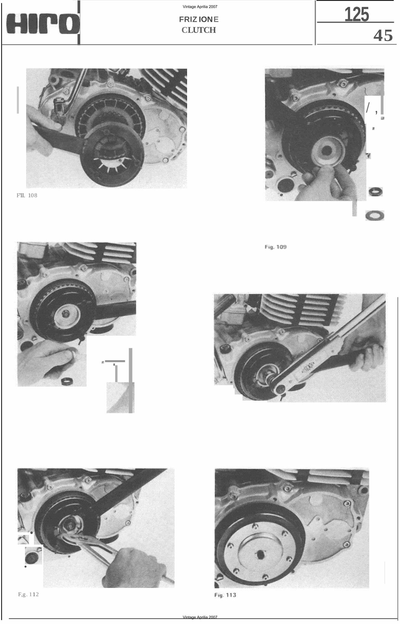
45 125FRIZ IONE
CLUTCH
/ ,
F'II. 108
•
•
F,g . 1 12
Vintage Aprilia 2007
Vintage Aprilia 2007
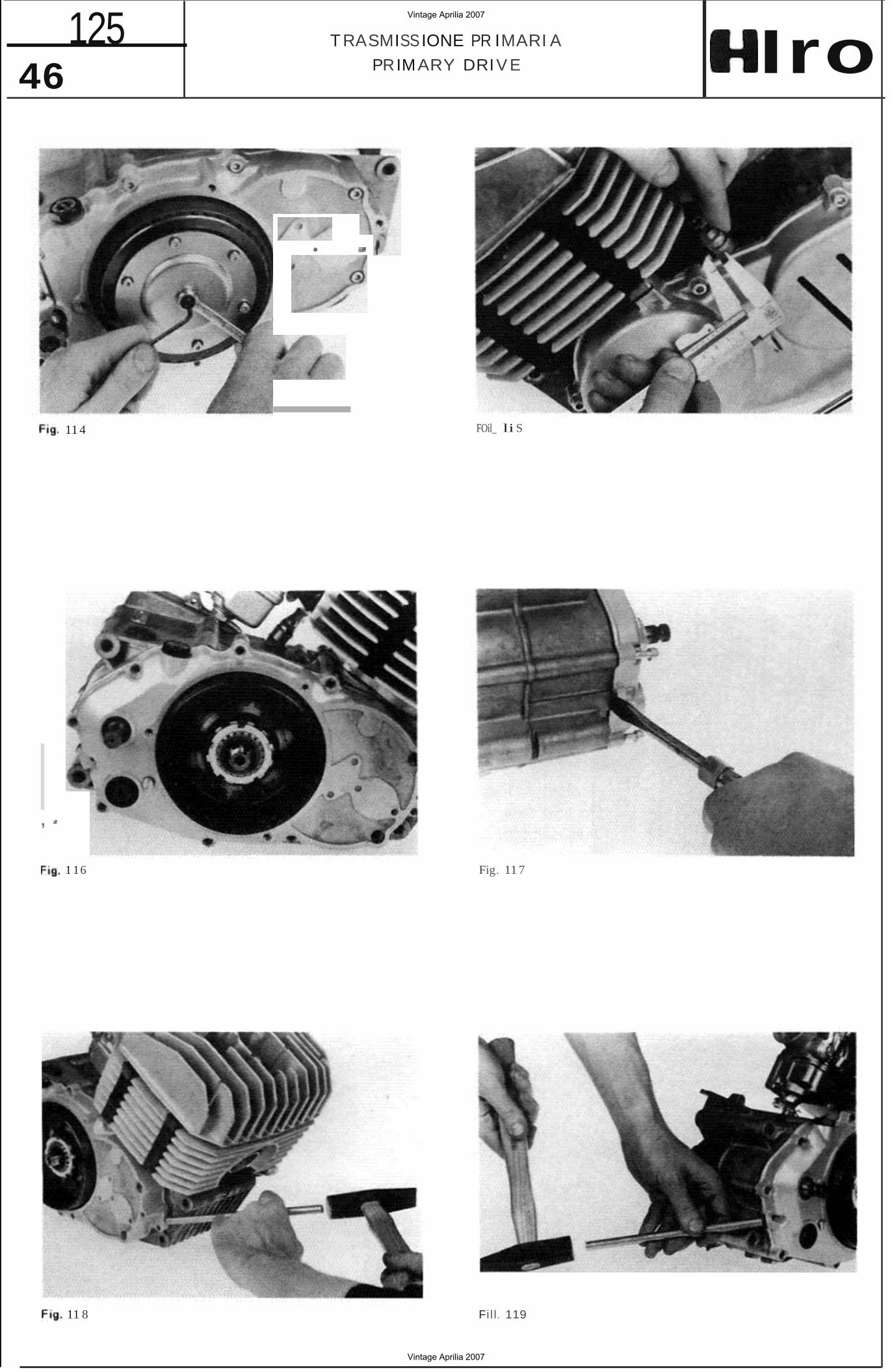
46 125 TRASMISSIONE PR IMARI A
PRIMARY DRIV E Iro
• I
11 4 FOil_ li S
Fig. 11 7
,
1 16
11 8 Fill. 119
Vintage Aprilia 2007
Vintage Aprilia 2007
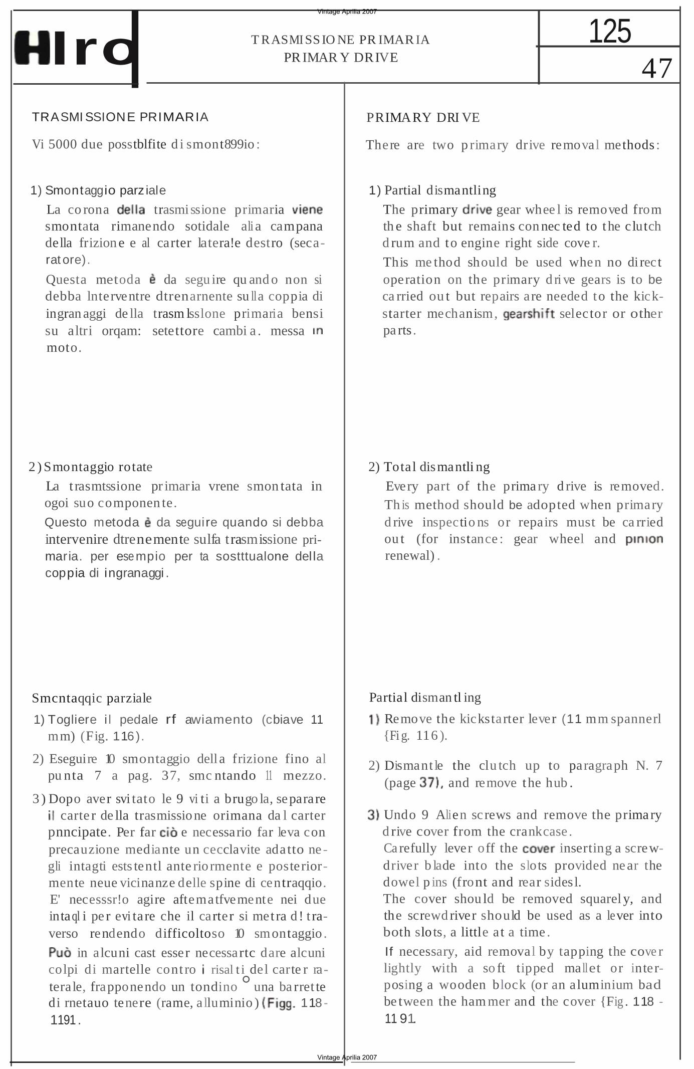
47 125T RASMI SS IO NE PR IMAR IA
PR IMAR Y DRIVEIro TRASMI SSIONE PRIMARIA
Vi 5000 due posstblfite d i smont899io :
1) Smontaggio parz iale
La co rona trasmissione primaria smontata rimanendo sotidale ali a campana della frizione e al carter latera!e destro (secarat ore).
Questa metoda da segu ire qu and o non si debba lnterventre dtrenarnente su lla coppia di ingran aggi de lla trasm lsslone primaria bensi su altri orqam: setettore cambi a . messa moto.
2 ) Smontaggio rotate
La t rasmtssione pr imaria vrene smon tata in ogoi suo componen te.
Questo metoda da seguire quando si debba intervenire dtrenemente sulfa trasmissione primaria. per ese mpio per ta sostttualone del la coppia di ingranaggi .
Smcntaqqic parziale
1) Togliere i l pedale rf awiamento (cbiave 11 mm) (Fig. 116).
2) Eseguire 10 smontaggio dell a frizione fino al pu nta 7 a pag. 37, smc ntando 11 mezzo.
3 ) Dopo aver svi tato le 9 vi ti a brugo la, separare carte r de lla trasmissione orimana da l carter
pnncipate. Per far e necessario far leva con precauzione mediante un cecclavite adatto ne gli intagti ests tentl ante rio rmente e posteriormente neue vicinanze delle spine di centraqqio. E' necesssr!o agire aftematfvemente nei due intaql i pe r evi tare che il carter si met ra d ! t raverso rendendo difficoltoso 10 smontaggio .
in alcuni cast esser necessartc dare alcuni colpi di martelle cont ro risal t i del carte r raterale, frapponendo un tondino ° una ba rret te di rnetauo tenere (rame, alluminio ) 118 1191 .
PRIMARY DRI VE
There are two p rimary drive removal methods :
1) Partial dismantling
The primary gear whee l is removed from th e shaft but remains con nec ted to the clutch d rum and to engine right side cove r.
This me thod should be used when no di rect operation on the primary d ri ve gears is to be ca rried ou t but repairs are needed to the kickstarter mechanism, selector or other pa rts .
2) Total dismantli ng
Every part of the prima ry d rive is removed. Th is method should be adopted when primary d rive inspectio ns or repairs must be ca rried ou t (for instance : gear wheel and renewal) .
Partial disman tl ing
Remove the kickstarter lever (11 mm spannerl {Fi g. 116 ).
2) Dismant le the clu tch up to paragraph N. 7 (page and remove the hub .
Undo 9 Alien sc rews and remove the prima ry d rive cover from the crankcase . Ca refully lever off the inserting a screwdriver b lade into the slots provided ne ar the dowel p ins (front and rear sidesl. The cover shou ld be removed squarel y, and the screwd river should be used as a lever into both slo ts, a little a t a time .
If necessary, aid removal by tapping the cove r lightly with a so ft tipped mallet or interposing a wooden block (or an aluminium bad be tween the ham mer and the cover {Fig . 118 11 91.
Vintage Aprilia 2007
Vintage Aprilia 2007
48 125 T RA$MI SSIONE PRIM A RI A
PRIMARY DRIV E
4) Come si vede in Fig. 121 la corona della trasrmsstone primaria rtrnane vincolata a! separatore . Se a questa pun to tosse necessaria separare la corona dal separators e della campana
friz ione vi sana due possibilita:
etterrare la dentatura oicco!a della corona in una morse munita di false qanasce in rnate riale tenere e svitare ta ghiera di fissaggio della carnpana con la chiave N. 8.
b) rimon tare iI separato re e la corona ed eftettua re 10 smon taggio secondo Ie ist ruzioni impartite per 10 smontaggio totale.
Montaggio
1) Montare I particctar i in tern! eventualmente smontati .
2) Cospargere Ie superfici di giunzione con un leggero straro di mastics gommoso {Estak 20 Arexonsl.
31 Montare i l sepatatore insieme can la corona curando i! corretto imbocco albert e degl i ingranaggi.
Completa re I'accostamento can leggeri col di mazzuo!o ben distribuiti, evitando che il separatore Sl metta di traverse (Fig. 1221.
4) Serrare Ie 9 viti a brugola di chiusura .
5) Montare la frizione secondo Ie istruzion i del capitclo relative ed il pedale della messa in mota.
Smo ntaggio t otale
1) Svitare completamente can una chiave da 11 mm il bullone di f issagg io del pedale di avvia mente e sfilare l ! perno stesso dall'albenno (Fig. 123}.
21 Smontare campietamente i l gruppo t r tztone come descritto net capi tcto relative.
3) Dopo aver svitato te 9 viti a brugola. seoarare il ca rter de lla trasmissione primaria dal carter principals.
Per far cio e necesseno far leva can precauzione mediante un aoarto cacctavtte negli intagli esistent! anteriormente e oostertormente nelle vtctnanze delle sotned! centraggio (F ig. 1241.
E' necessaria agire atternativarnente net due intagli per evitere cbe i l carter si metta di t ra verso, rendendo diffico ltoso 10 smontaggio.
Pub in alcun i cas! esser necessarto dare alcuni leggeri co lpi dl martello centro il risalto del carter laterale, f rapponendo un tond ino 0 una barrette di metallo tenero [rame. alluminio ) (F ig. 125).
4) As shown in Fig. 121, the primary drive gear wheel comes out with the side cover. If it necessary to remove it from the cover and from the clutch drum, two methods can be used:
a} hold the gear wheel in a vice equipped soft jaw and loosen the clutch drum ring nut special tool N. 8;
b) refit side cover and gear wheel and follow dismantling procedure shown in "total dismantling" chapter.
Rebu il d
1) Ref it the inner parts that have been removed.
2) Smear a l ight coat of non -settinq joint ing compound (Arex ons Estak 20 ) on the mating surfaces.
3) Replace the side cover with the gear wheel taking care of the cor rect shaft and gear engagements.
Push the cover home squarely using a soft faced mallet ( Fig. 1221.
4) Tighten the Allen that secure the cover to the crankcase.
51 Reassemble the clutch following the d irections given the relevant chapter and ref it the kickstarter lever.
Total dismantl ing
1) Complete ly loosen the k ickstarter lever retain ing bo lt using an 11 mm spanner and reo move the lever from the shaft 123l.
2) Remove the clutch assembly as described in the relevant chapter.
31 Undo 9 Allen screws and remove the prima ry drive cover from the crankcase.
Carefully lever off the cover a screwdriver blade into t he provided near thedowel and rea r ( Fig. 124 ).
The cover shou ld be removed squarely, andthe screwd river shou ld be used as a lever intoboth slots. a little at a time .
If necessary , aid removal by tapping the coverl ightl y with a soft tipped mallet or interposing a wooden block (or an alumin ium bar)between the hamme r and the cover (Fig. 125).
Vintage Aprilia 2007
Vintage Aprilia 2007
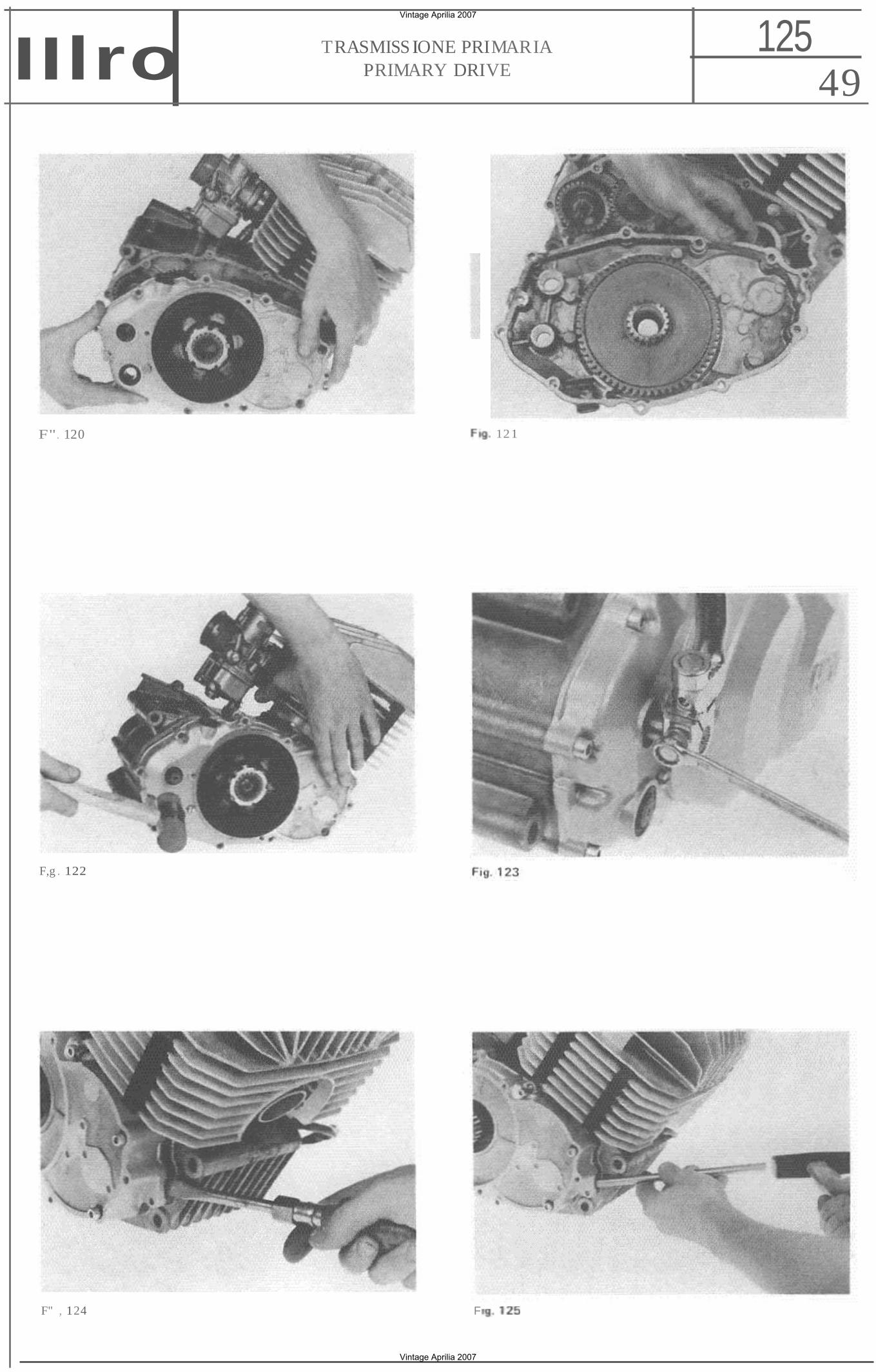
49 125TRASMISS IONE PRIMARIA
PRIMARY DRIVEIIlro
F". 120 12 1
F,g . 122
F" , 124 F
Vintage Aprilia 2007
Vintage Aprilia 2007
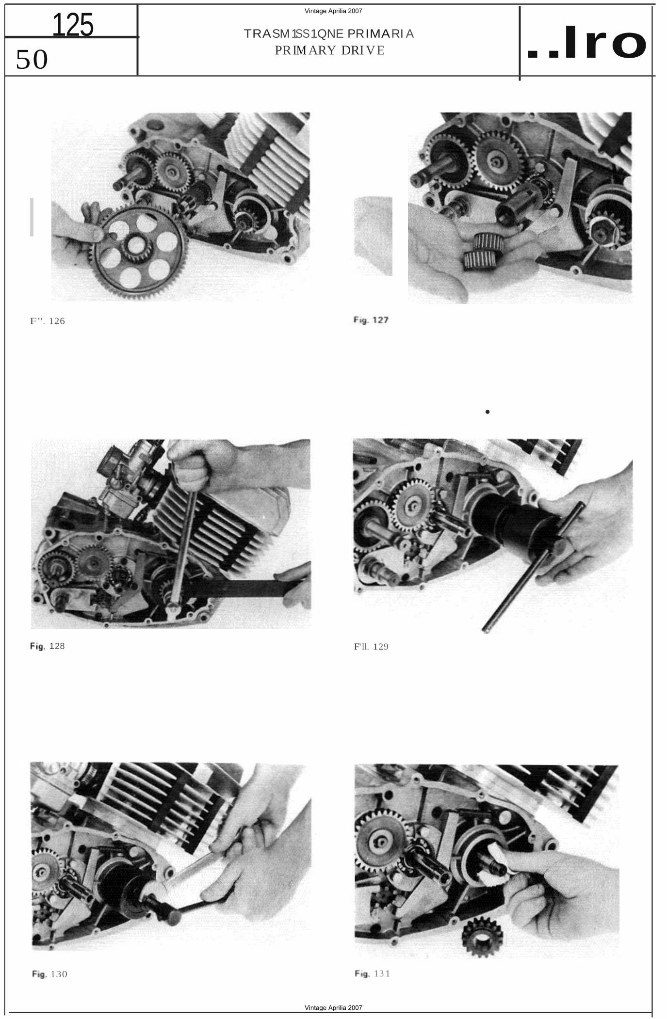
125 TRASM1SS1QNE PRIMARI A PRIM ARY DRI VE ..Iro50
F". 126
128
130
•
F' ll. 129
13 1
Vintage Aprilia 2007
Vintage Aprilia 2007
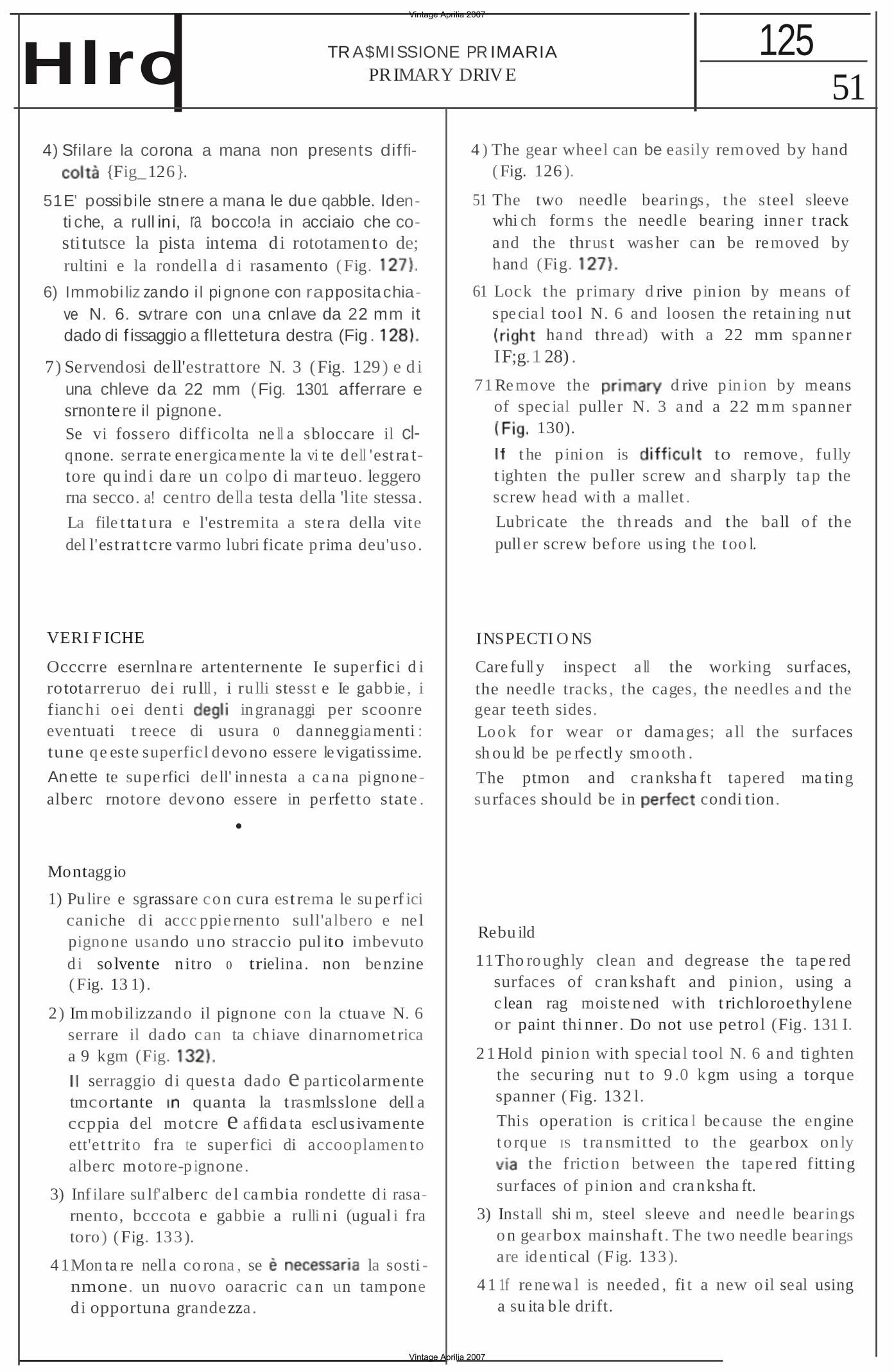
51 125TR A$MISSIONE PR IMARIA
PRIMARY DRIV EHlro 4) Sfilare la corona a mana non presents diffi
{Fig_126}.
51E' possibi le stnere a mana le due qabble. ldenti che, a rull ini, ra bocco!a in acciaio che costi tutsce la pista intema di rototamen to de; rultini e la rondell a d i rasamento ( Fig.
6) Immobi liz zando i l pignone con rappositachiave N. 6. svtrare con una cnlave da 22 mm it dado di f issaggio a fllettetura destra (Fig .
7) Servendosi de ll'estrattore N. 3 (Fig. 129) e d i una chleve da 22 mm (Fig. 1301 afferrare esrnonte re il pignone.Se vi fossero diff icolta ne ll a sbloccare il clqnone. serra te energica mente la vi te dell 'est ra ttore qu ind i da re un colpo di mar teuo. leggerorna secco. a! centro della testa della 'lite stessa.La file t ta t ura e l'estremita a ste ra della vite del l'est rat tcre varmo lubri ficate prima deu'uso.
VERI F ICHE
Occcrre esernlna re artenternente Ie superfici d i rototarreruo de i ru lll , i ru lli stesst e Ie gabbie , i fianc hi oei dent i ingranaggi per scoonre eventuati t reece di usura 0 danneggiamenti : tune qe este superficl devono essere le vigatissime.
An ette te supe rfici dell' innesta a ca na pignonealberc rnotore devono essere in pe rfetto state .
•
Montaggio
1) Pu lire e sgrassare con cura est rema le su pe rf ici caniche d i accc ppie rnento sull'albero e ne l pignone usando uno straccio pul ito imbevuto d i so lvente nitro 0 trielina . non benzine ( Fig. 13 1) .
2 ) Im mobilizzando il pignone con la ctuave N. 6 serrare il dado can ta chiave dinarnomet rica a 9 kgm (Fig.
serraggio d i quest a dado e pa rticolarmente tmcortante quanta la t rasmlsslone dell a ccppia del motcre e affida ta escl us ivamente ett'et tr it o fra te super fici di accooplamen to alberc motore-pignone.
3) Inf ilare su lf'alberc de l cambia rondette d i rasarnento, bcccota e gabbie a ru lli n i (ugual i fra toro) ( Fig. 133).
4 1Mon ta re nell a co rona , se la sosti nmone. un nuovo oaracric ca n un tampone d i opportuna grandezza .
4 ) The gear wheel can be easily rem oved by hand ( Fig. 126 ).
51 The two needle bearings , t he steel sleeve whi ch form s the needle bearing inne r t rack and the thrus t was her can be re moved by hand (Fig.
61 Lock t he primary d rive pinion by means of specia l too l N. 6 and loosen the retain ing nut
ha nd thread) with a 22 mm spanne r IF;g.1 28) .
71 Re move the d rive pin ion by means of spec ial puller N. 3 a nd a 22 m m spanner
130).
t he pini on is to remove , fu lly t ighten the puller screw an d sharply ta p the screw head wi th a mallet .
Lubricate the th reads and t he ball o f the puller screw before us ing t he t oo l.
INSPECTI O NS
Care fu ll y inspect a ll the working surfaces,the needle tracks , the cages, the needles a nd thegear teeth sides.Look fo r wear o r damages; a ll the surfacessh ou ld be pe rfectly smooth .
The ptmon and c ra nksha ft tapered ma tingsurfaces should be in condi tion.
Rebu ild
11Tho roughly clean and degrease the ta pe red surfaces of c ran kshaft and pinion , using a c lean rag moiste ned with t richloroethylene or paint thi nner . Do not use petro l (Fig. 131 I.
2 1 Hold pinion with specia l tool N. 6 a nd tighten the securing nu t t o 9 .0 kgm using a torque spanner ( Fig. 132 l.
This operation is c rit ica l because the engine t o rque IS t ra nsmitted to the gearbox on ly
t he friction between the tape red fitting surfaces of pin ion a nd cra nksha ft.
3) Install shi m, steel sleeve and need le bearings on gearbox mainshaft . The two needle bearings are ide ntical (Fig. 133).
4 1 1f re ne wa l is needed , fi t a new o il seal using a su ita ble drift.
Vintage Aprilia 2007
Vintage Aprilia 2007
52 125 TRASMISSIONE PR IMARI A
PR IMARY DRIVE
La rondelta posta sot to il pa raolio ha uno spi gala smussato che va r ival t o verso I' interno del motore (Fig. 134).
5) lnfltere ra corona sulle gabbie a rull ini dopo avert! leggermente lubrificat i (Fig. 13 5); far ingranare il pignoncino esistente su i reno delIa corona con " ingranaggio folie della rnessa in moto (Fig_ 136).
Accertarsi della presenza e delle buone condizioni del grande OR mon tato sulfa corona.
6) Dopo aver cosoarso Ie superf ici di giunzione con un leqqerc st rato d i mastlce gommoso {Estak 2 Arexons} , montere il cer ter ta tera!e. assestanootc . prima d i serrate Ie 9 vit i, con qualche leggero colpc di mazzuolo di p lasti ca, ben di st ribu ito su tutto il ca rter la te rale IF;g. 1371.
Beneath the o i l seal t here is a washer which shou ld be f i tted wi th the chamfered side facing towards the c rankcase (Fig. 1341.
5) Slightly lubricate the needle roller bearings and insert the gear wheel on them (Fig. 135 ). The small gear beh ind the pnmary drive crown wheel should engage wi th the kick . starter idle gear (Fig. 136).
Check tha t the large a ·ring is properly f i tted and is in good condi t ion.•
6) Smear the mating surfaces with a ligh t of non-sett ing j o intin g compound (Arexons Estak install t he side cover, tapping it w ith a plast ic t ip malle t (t he cover shoul d go home squarely ) and ti ghten the 9 A llen sc rews (Fig.
Vintage Aprilia 2007
Vintage Aprilia 2007
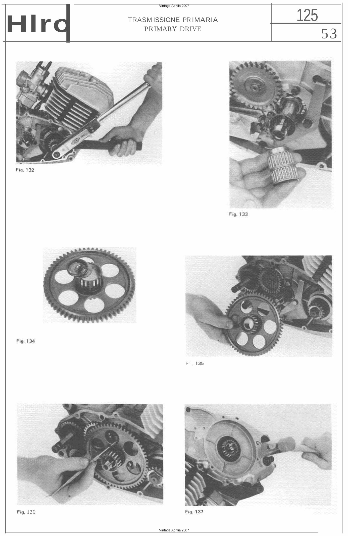
53 125TRASM ISSIONE PR IMARIA
PRIMARY DRIVEHlro
F" ,
136
Vintage Aprilia 2007
Vintage Aprilia 2007
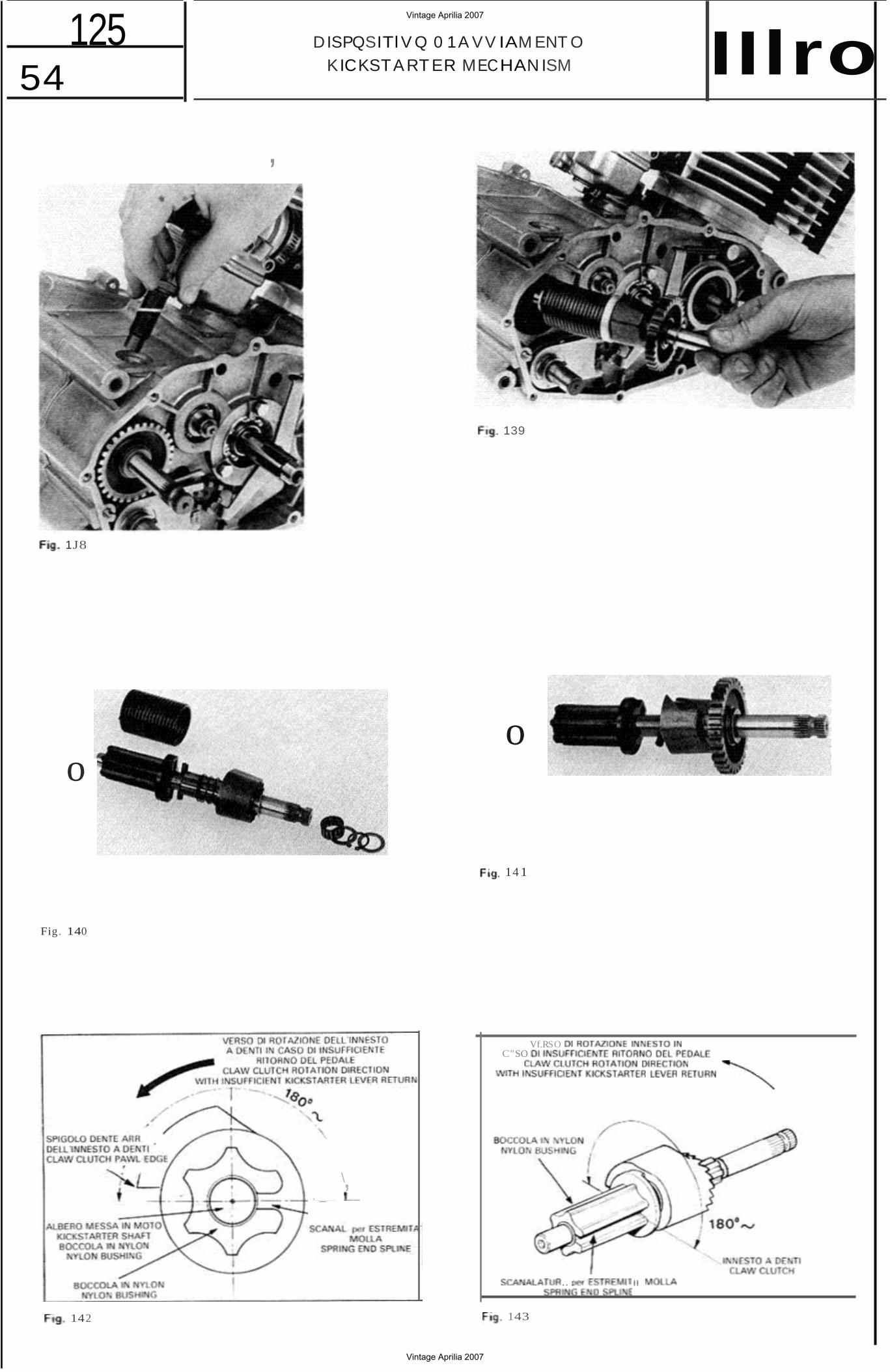
54 125 DISPQSITl V Q 0 1A VV IAM ENT O
KICKSTART ER MECHAN ISM IIlro ,
o o
14 1
Fig . 140
Vf.RSO C"SO
\, . _
.. .. 143
1J8
139
142
Vintage Aprilia 2007
Vintage Aprilia 2007
55 Hlro OISPOSITIVO 0 1AVV IAMENTD 125 K ICKSTARTER MECHAN ISM
DISPOSITlVQ 01 AVVI AMENTO
Smontaggio
1) Srnontere il ca rte r destro tseparatore} insieme alia campana della f rizione e alia corona della t rasmissione primerla, come descrttto nel cap itola " Smo ntaggi o pa rziatemaria" .
21Svitare te vue d i termo oota te d i guarnizione rretatlica (Fig. 138).
3) Estrarre moto.
it gruppo completo della messa In
Per evi tare che la fondo all'a lberino posse
della caoere di battu ta costa in
all'in temo, esegui re I'operazlooe con il (F;g. 1391.
4) Togtiendo t'eoeuo scomposto ne r elemenu
Montaggio
1) II montaggio dei vari eterrenn sull'albero delI'avviemento ve fane secondo la disposiz ione indicate nella 141 .
La boccola in nyl on su cu i agisce la
pasizionata da una spina che eu rave rsa be ro .
Afflnche l'atberc abbia un giusto rito rno sotto I'azione de lla rnolla. occorre che la pa rte scorrevole dell'in nesto a denti. venga infilata sulle scanal atu re con dicato in Fig. 142.
accadere che. a causa motte e molla, con questc c rtentamento non VI sta un sut ficiente ritorn o qu es to caso occc rre variare la poslzlone dell a parte scorrevole del l'lnnesto a den t i ruotandola nel verso indicate del ta Fig. 143, di un sesto d i giro rispe tto all'albero (te scenalature sono sei, quindi ruoterta di una scanala tu ra; t'anqo10 viene aumenta tol.
2) Montare il gruppo facendo attenzione estremita dell 'al berino e della spettive sedi della f langia·supporto (Fig. 145).
Per evi tare che la rondella di battuta posse cadere. f issa rla boccota in nylon con un c o'di grasso.Avvita re d i due 0 tre giri latermo.
KICKSTARTER MECHANISM
Disassembly
1) Remove the r ight side cover complete with primary drive gear wheel and clu tch drum, as described in chap ter "Partial disman tling
trasrnissione prj pri mary d rive " .
2) Remove the se t sc rew with its washer (Fig. 138) .
3) Wi thdraw the complete kickstar ter mechanism assembly.
The should be placed In vert ical position when ca rry ing out th is ope rati on, in o rde r to avoi d any risk of d ropping the th rust
mo to re verticele washe r that is loca ted at the end o f the shaft in to the cran kcase (Fig. 139 ).
il gruppo puc esser 41 The kickstarter mechanism can be d isassembl (Fig. 14 0) . ed by remo vi ng the retaining circl ip (Fig. 140 ).
Reassembly1) The various parts of the mechan ism should be
reassembled fo llowing the lay out shown in Fig. 14 1.mol la
t'a t The nyl on bushing on whi ch the spring works is posi tioned by a pin which passes through the sha ft .
To ensure a prope r kicks tar ter lever return , the Sliding port ions of the ratc het mech anism
t'orienta mento in. should be inst alled on the sha ft as shown in Fig. 142 .
di diffe renze fra It may be necessary to rotate a sixth of a turn the position of the sliding part of the ratche t
delt'albero. In mechan ism to ensu re a proper klcksterter lever re turn (refe r to Fi g. 143 ). (The shaft splines are six so in the above case, move the posi t ion of the ra tchet the d irec tion shown and place it the next spline ).
2) Insta ll t he complete kicksterter mechanism completo de tt'avviamento
assembly , taking care to properly fit the a t correttc imbocco de lla shaft and spring ends in their housings in the
molla nelle rio support flange (Fig. 14 51.
To avoid any risk o f d ropping the thrust washer in to the crankcase, hold it in contact with the ny lon bush ing by means of a dab of
grossa vire di Screw fo r two or three turns the big re taini ng screw.
Vintage Aprilia 2007
Vintage Aprilia 2007
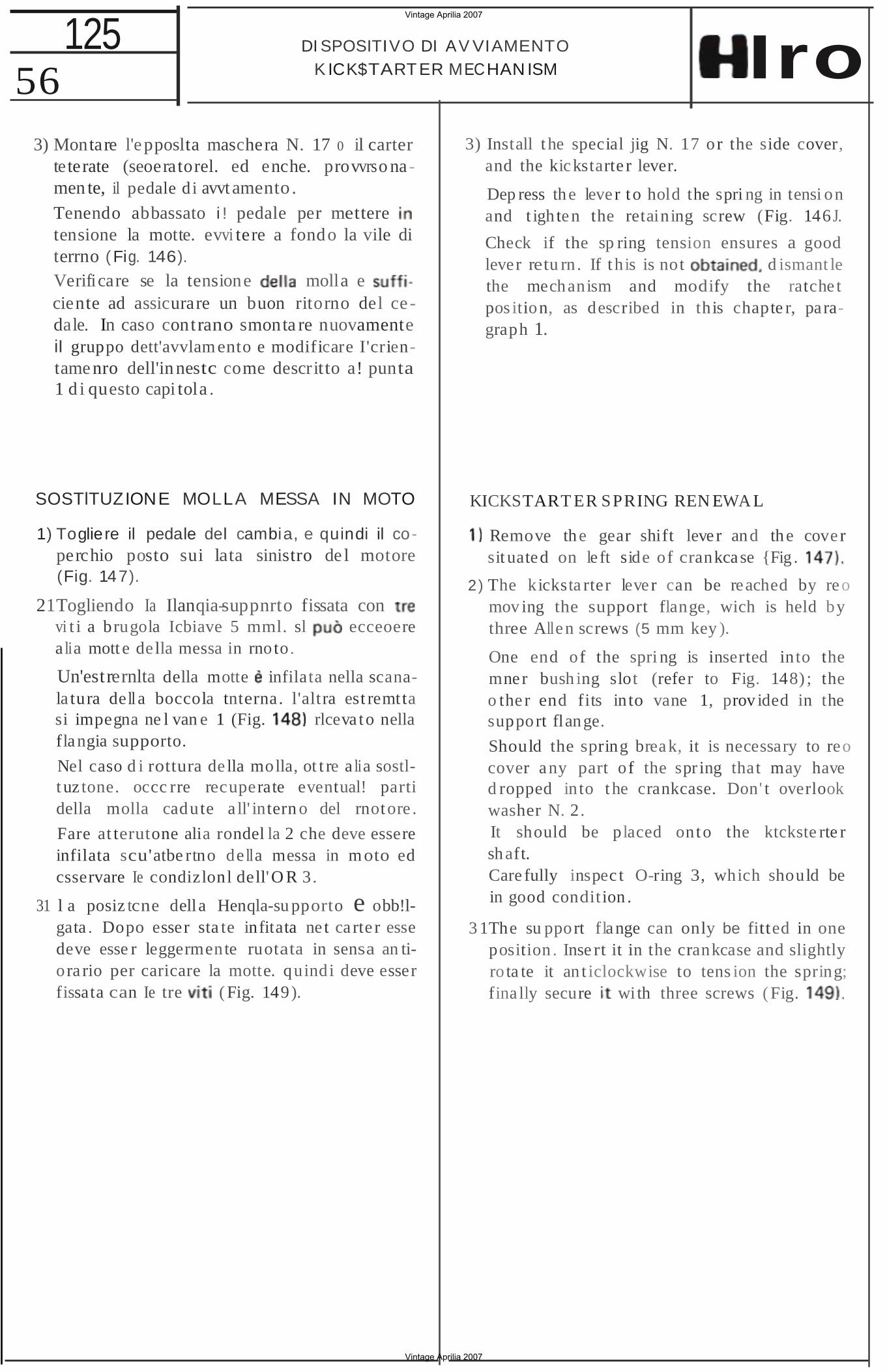
56 DI SPOSITIVO DI AV VIAMENTO
K ICK$TART ER MECHAN ISM Iro125
3) Montare l'epposlta maschera N. 17 0 il carter teterate (seoeratorel. ed enche. provvrso namen te, il pedale d i avvt amento . Tenendo abbassato i ! pedale per mettere tensione la motte. evvi tere a fondo la vile di terrno (Fig. 146).
Verifi care se la tensione molla e ciente ad assicurare un buon ritorno del ce dale. In caso contrano smonta re nuovamente iI gruppo dett'avvlamento e modificare I'crientame nro dell'in nestc come descritto a! punta 1 d i questo capi tola .
SOSTlTUZIONE MOLLA MESSA IN MOTO
1) Togliere il pedale del cambia, e quindi il coperchio posto sui lata sinistro de l motore (Fig. 147).
21Togliendo Ia Ilanqiasuppnrto fissata con vi t i a brugola Icbiave 5 mml. sl ecceoerea lia mott e de lla messa in rno to.
Un'estrernlta della motte infilata nella scanala tura de ll a boccola tnterna. l'altra est remttasi impegna ne l van e 1 (Fig. rlceva to nellaflangia supporto.
Nel caso d i rottura de lla molla, ot t re a lia sostlt uz tone. occc rre recuperate eventual! partidella molla cadute a ll' intern o del rnotore .
Fare at terutone alia rondel la 2 che deve essereinfilata scu'atbe rtno de lla messa in moto edcsservare Ie condizlonl dell'O R 3.
31 l a posiz tcne della Henqla-su pporto e obb!lgata . Dopo esser sta te infitata ne t ca rte r esse deve esse r leggermente ruotata in sensa an tio ra rio per caricare la motte. quindi deve esser fissata can Ie tre ( Fig. 149).
3) Install t he special jig N. 17 o r the side cover, and the kickstarte r lever.
Dep ress the leve r to hold the spri ng in tensi onand t igh ten the retaining screw (Fig. 146 J.
Check if the sp ring tension ensures a good lever retu rn . If t his is not d ismant le the mechanism and modify the ratche t pos ition, as described in this chapte r, pa ragraph 1.
KICKSTART ER SPRING REN EWA L
Remove the gear shift leve r and the cove r sit uated on le ft side of crankcase {Fig .
2) The kicksta rter leve r can be reached by reo mov ing the support flange, wich is held by three Allen screws (5 mm key ).
One end of the spri ng is mner bush ing slot (refer o the r end fits in to vane support flange.
inserted to Fig.
1, prov id
into 148) ; ed in
the the the
Should the spring break, it is necessary to reo cover any part of the spr ing that may have d ropped in to t he crankcase. Don' t overlook washer N. 2. It should be placed onto the ktckste rte r shaft. Care fully inspec t O-ring 3, which should be in good condition .
3 1The su pport flange can only be fitted in one position . Inse rt it in the crankcase and slightly ro ta te it an t iclockwise to tens ion the spring; fina lly secure wi th three screws ( Fig.
Vintage Aprilia 2007
Vintage Aprilia 2007
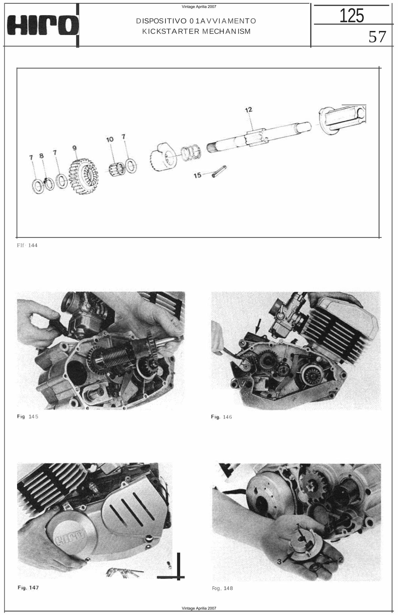
57 125DISPOSITIVO 0 1A VVI A MENTO
KICKSTARTER MECH AN ISM
FIf· 144
14 5 14 6
Fog, 148
Vintage Aprilia 2007
Vintage Aprilia 2007
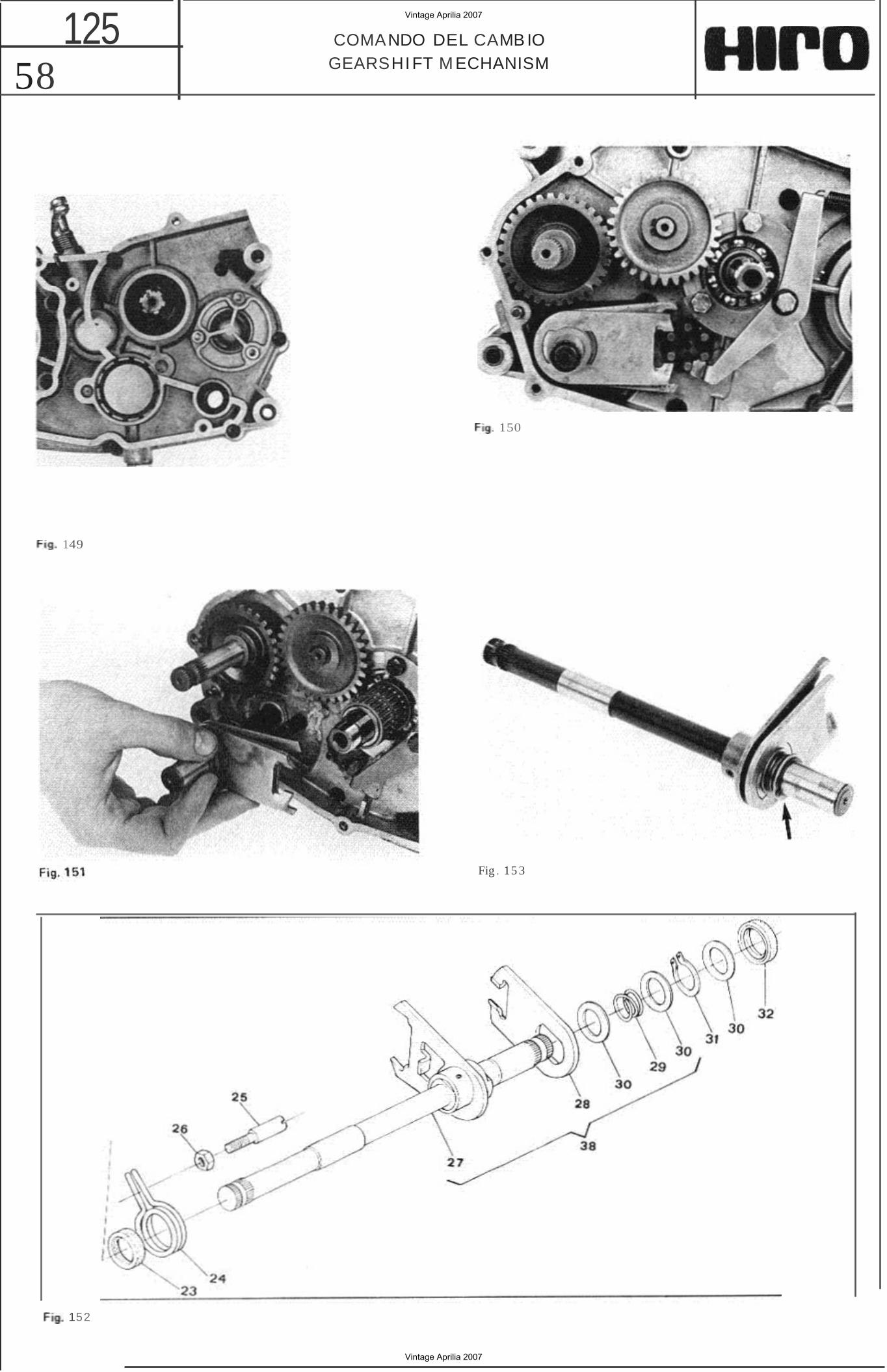
58 125 COMANDO DEL CAMB IO
GEARSHIFT M ECHANISM
150
149
Fig . 15 3
152
Vintage Aprilia 2007
Vintage Aprilia 2007
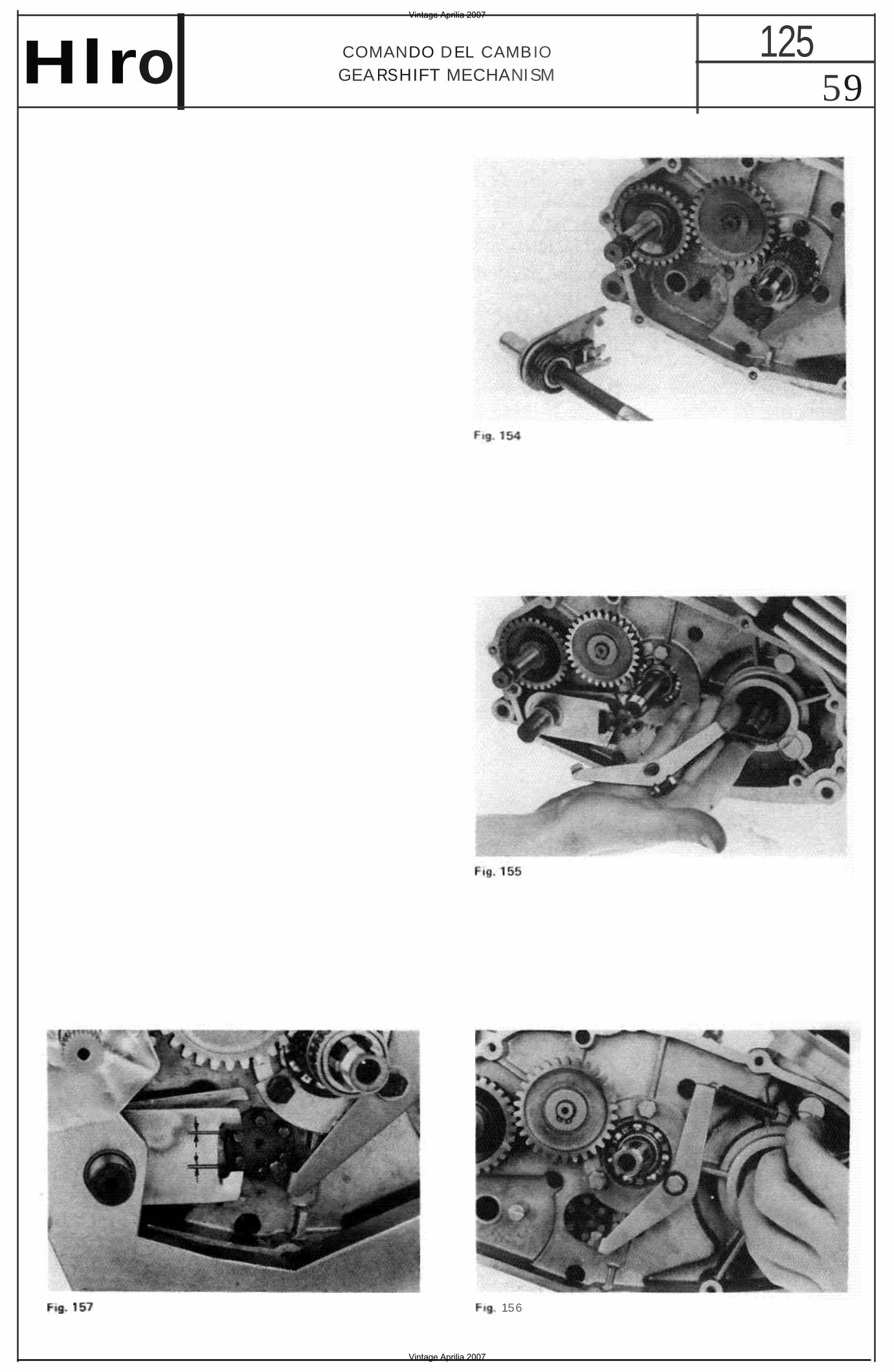
59 125COMANDO DEL CAMBIO
GEA RSHIFT MECHANISMHlro
156
Vintage Aprilia 2007
Vintage Aprilia 2007
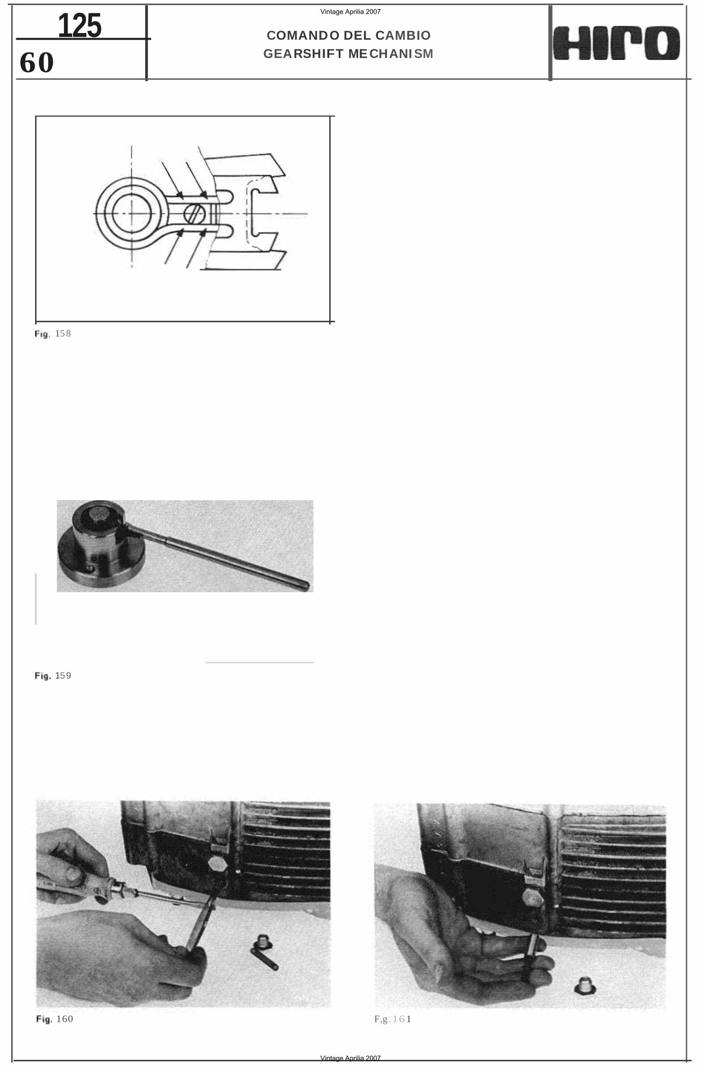
60 125 COMANDO DEL CAMBIO
GEARSHIFT ME CHANI SM
15 8
159
160 F,g.16 1
Vintage Aprilia 2007
Vintage Aprilia 2007
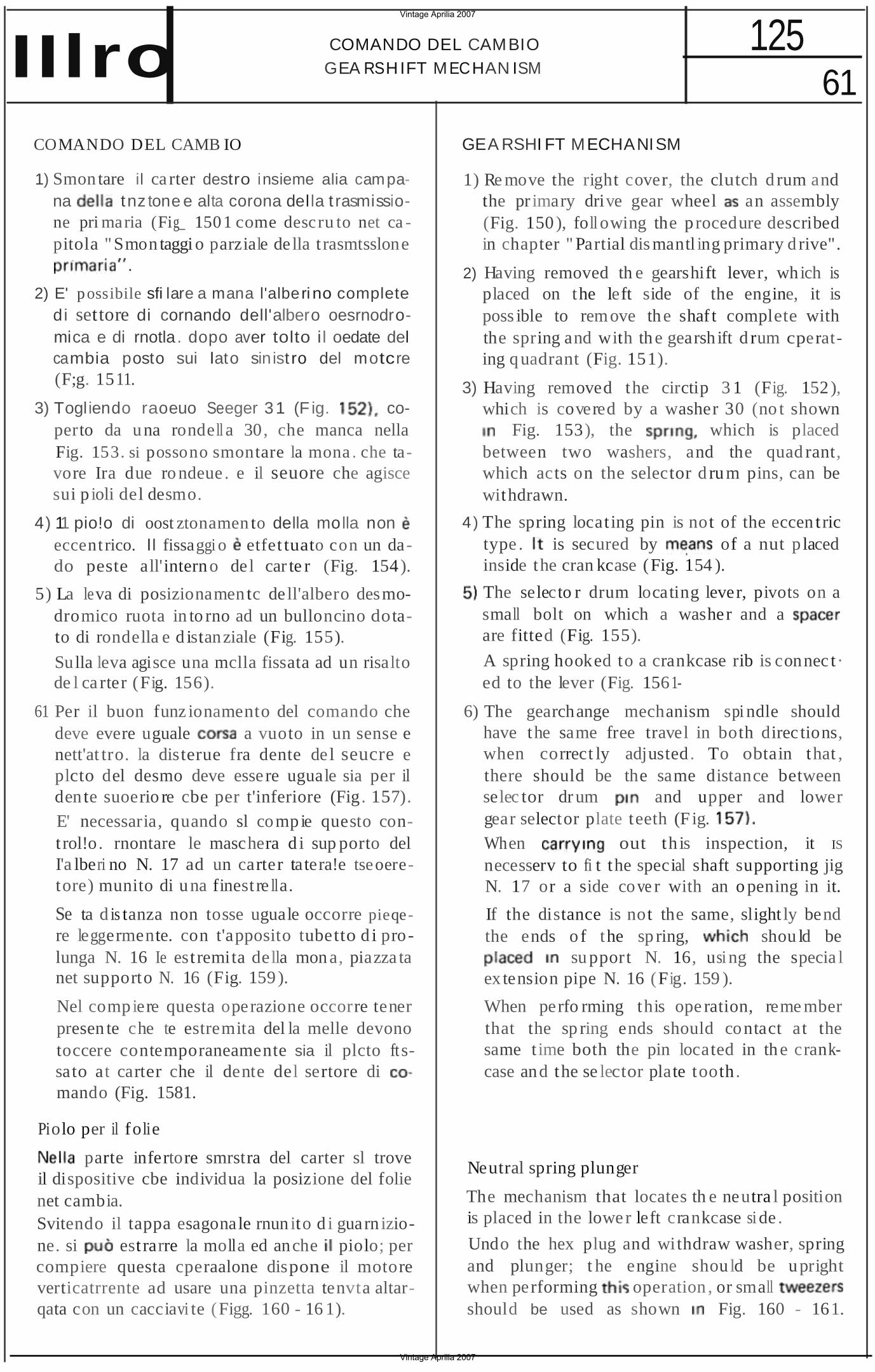
61 COMANDO DEL CAMBIO 125
GEA RSHIFT MECHAN ISMIIlro COMANDO DEL CAMB IO
1) Smon tare il ca rter destro insieme alia campana tnz tone e alta corona della t rasmissione pri maria (Fig_ 1501 come descru to net ca pitola "Smon taggi o parziale de lla t rasmtsslone
. .
2) E' possibile sfi lare a mana l'alberi no complete di settore di cornando dell'albero oesrnodromica e di rnotla . dopo aver tolto i l oedate del cambia posto sui lato sin ist ro del motcre (F;g. 1511.
3) Togliendo raoeuo Seeger 31 (F ig. coperto da una rondell a 30, che manca nella Fig. 153. si possono smontare la mona . che tavore Ira due ro ndeue . e il seuore che agisce sui p ioli del desmo.
4) 11 pio!o di oost ztonamen to della molla non eccent rico. II fissaggi o etfet tuato con un dado peste all'interno de l car te r (Fig. 154).
5) La leva di posizionamen tc de ll'albero desmodromico ruota in to rno ad un bulloncino dotato di rondella e d istanziale (Fig. 155).
Sulla leva agisce una mclla fissata ad un risalto de l ca rter (Fig. 156).
61 Per il buon funz ionamento del comando che deve evere uguale a vuoto in un sense e nett'at tro. la disterue fra dente de l seucre e plcto del desmo deve esse re uguale sia per il den te suoerio re cbe per t'inferiore (Fig. 157). E' necessaria, quando sl compie questo cont rol!o. rnontare le maschera d i sup porto del I'a lberi no N. 17 ad un carter tatera!e tseoeretore) munito di una finest re lla.
Se ta d is tanza non tosse uguale occorre pieqere leggermente. con t'apposito tubetto d i prolunga N. 16 Ie est remita della mon a, piazza ta net supporto N. 16 (Fig. 159 ).
Nel compiere questa operazione occorre tener presen te che te estremita del la melle devono toccere contemporaneamente sia il plcto ft ssato at carter che il dente del sertore di mando (Fig. 1581.
Piolo per il folie
parte infertore smrstra del carter sl troveil dispositive cbe individua la posizione del folienet cambia.Svitendo il tappa esagonale rnun ito d i guarn izione. si est rarre la molla ed anche piolo; percompiere questa cperaalone dispone il motoreverticatrrente ad usare una pinzetta tenvta altarqata con un cacciavi te (Figg. 160 - 16 1).
GEA RSHI FT MECHANISM
1) Re move the right cover, the clutch d rum and the pr imary drive gear wheel an assembly (Fig. 150 ), foll owing the p rocedure described in chapter " Partial dis mantl ing primary d rive".
2) Having removed th e gearshift lever, which is placed on the left side of the engine, it is poss ible to remove the shaf t complete with the spring and with the gearsh ift d rum cperating q uadrant (Fig. 151).
3) Having removed the circtip 3 1 (Fig. 152 ), which is covered by a washer 30 (no t shown
Fig. 153), the which is placed between two washers, and the quad rant, which acts on the selector d rum pins, can be withdrawn.
4) The spring locat ing pin is not of the eccen t ric type . is secured by of a nut p laced inside the cran kcase (Fig. 154 ).
The selecto r drum locating lever, pivots on a small bolt on which a washer and a are fitted (Fig. 155).
A spring hooked to a crankcase rib is connec t · ed to the lever (Fig. 156 1
6) The gearchange mechanism spi ndle should have the same free travel in both direc tions, when correct ly adjusted . To obtain that , there should be the same distance between selec tor dr um and upper and lower gear selector plate teeth (F ig. When out th is inspection, it IS
necesserv to fi t the special shaft supporting jig N. 17 or a side cove r with an o pening in it.
If the distance is not the same, slight ly bend the ends o f the sp ring, shou ld be
su pport N. 16, usi ng the specia l ex tension pipe N. 16 (Fig. 159 ).
When perfo rming this ope ration, reme mber that the sp ring ends should contact at the same t ime both the pin located in th e crankcase and the se lector plate tooth .
Neutral spring plunger
The mechanism that locates th e neutra l position is placed in the lowe r left crankcase si de .
Undo the hex plug and withdraw washer, spring and plunger; t he engine should be upright when performing operation , or small should be used as shown Fig. 160 - 161.
Vintage Aprilia 2007
Vintage Aprilia 2007
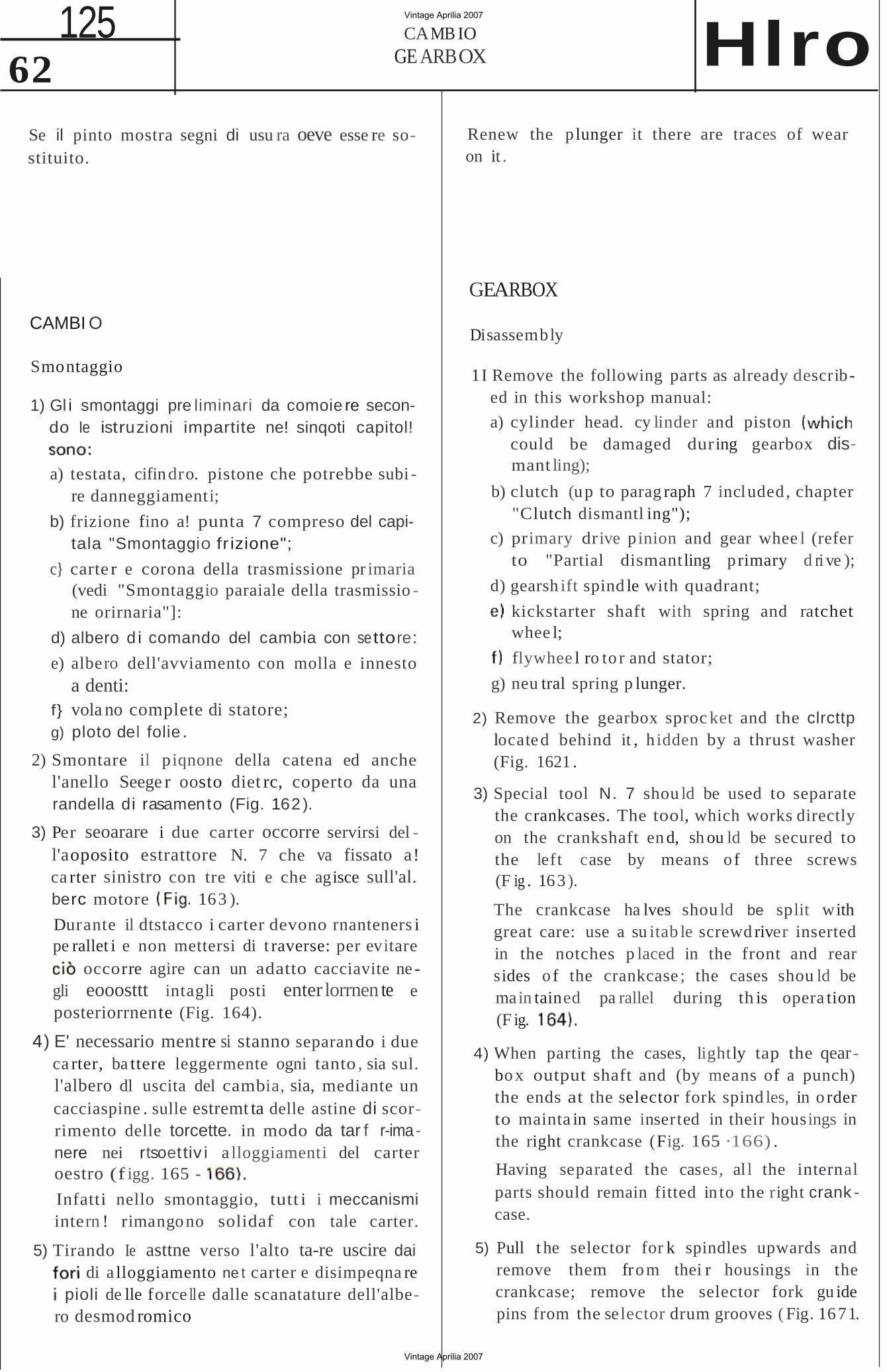
62 125 CAMB IO
GE ARBOX Hlro Renew the p lunger it there are traces of wearSe il pinto mostra segni di usu ra oeve esse re soon it .stituito.
CAMBI O
Smontaggio
1) Gl i smontaggi pre liminari da comoie re secondo Ie istruzioni impartite ne! sinqoti capitol!
a) testata, cifindro. pistone che potrebbe subi re danneggiamenti;
b) frizione fino a! punta 7 compreso del capitala "Smontaggio fr izione";
c} carte r e corona della trasmissione pr imaria (vedi "Smontaggio paraiale della trasmissio ne orirnaria"]:
d) albero d i comando del cambia con settore:
e) albero dell'avviamento con molla e innesto a denti:
f} vola no complete di statore;g) ploto del folie .
2) Smontare il p iqnone della catena ed anche l'anello Seege r oosto diet rc, coperto da una randella di rasamento (Fig. 162 ).
3) Per seoarare i due carter occorre servirsi del l'aoposito estrattore N. 7 che va fissato a! ca rter sinistro con tre viti e che agisce sull'al. berc motore 163 ).
Durante il dtstacco i carter devono rnanteners i pe rallet i e non mettersi di t raverse: per evitare
occorre agire can un adatto cacciavite ne gli eooosttt intagli posti enter lorrnen te e posteriorrnente (Fig. 164).
4) E' necessario mentre si stanno separan do i due ca rter, ba ttere leggermente ogni tanto , sia sul. l'albero dl uscita del cambia, sia, mediante un cacciaspine . sulle estremt ta delle astine di scorrimento delle torcette. in modo da tar f r-imanere nei rtsoettiv i a lloggiamenti del carter oestro (f igg. 165 -
Infatti nello smontaggio, tutt i i meccanismi intern ! rimango no solidaf con tale carter.
5) Tirando Ie asttne verso l'alto ta-re uscire dai di a lloggiamento ne t carter e disimpeqna re
pioli de lle force lle dalle scanatature dell'albero desmod romico (Fig. 1
GEARBOX
Disassembly
1I Remove the following parts as already described in this workshop manual:
a) cylinder head. cy linder and piston could be damaged during gearbox dismant ling);
b) clutch (up to parag raph 7 included , chapter "Clutch dismantl ing");
c) primary drive p inion and gear whee l (refer to "Partial dismantling p rimary d ri ve );
d) gearsh ift spind le with quadrant;
kickstarter shaft with spring and ratchet whee l;
flywhee l ro to r and stator;
g) neu tral spring p lunger.
2) Remove the gearbox sproc ket and the clrcttp located behind it , h idden by a thrust washer (Fig. 1621 .
3) Special tool N. 7 shou ld be used to separate the crankcases. The tool, which works directly on the crankshaft en d, sh ou ld be secured to the left case by means o f three screws (F ig . 163 ).
The crankcase ha lves shou ld be split with great care: use a su itab le screwd river inserted in the notches p laced in the front and rear sides o f the crankcase ; the cases shou ld be main tained pa rallel during th is opera tion (F ig.
4) When parting the cases, lightly tap the qearbox output shaft and (by means of a punch) the ends at the selector fork spind les, in o rder to mainta in same inserted in their housings in the right crankcase (Fig. 165 ·166) .
Having separated the cases, al l the internal parts should remain fitted in to the right crank case.
5) Pull t he selector for k spindles upwards and remove them fro m thei r housings in the crankcase; remove the selector fork gu ide pins from the selector drum grooves ( Fig. 1671.
Vintage Aprilia 2007
Vintage Aprilia 2007
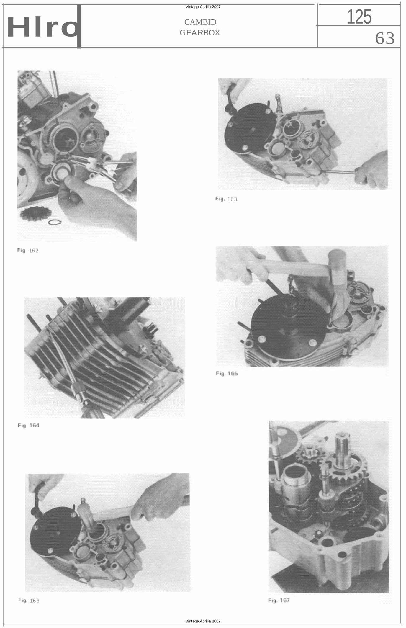
63 125CAMBID
GEARBOXHlro
16 3
16 2
166
Vintage Aprilia 2007
Vintage Aprilia 2007
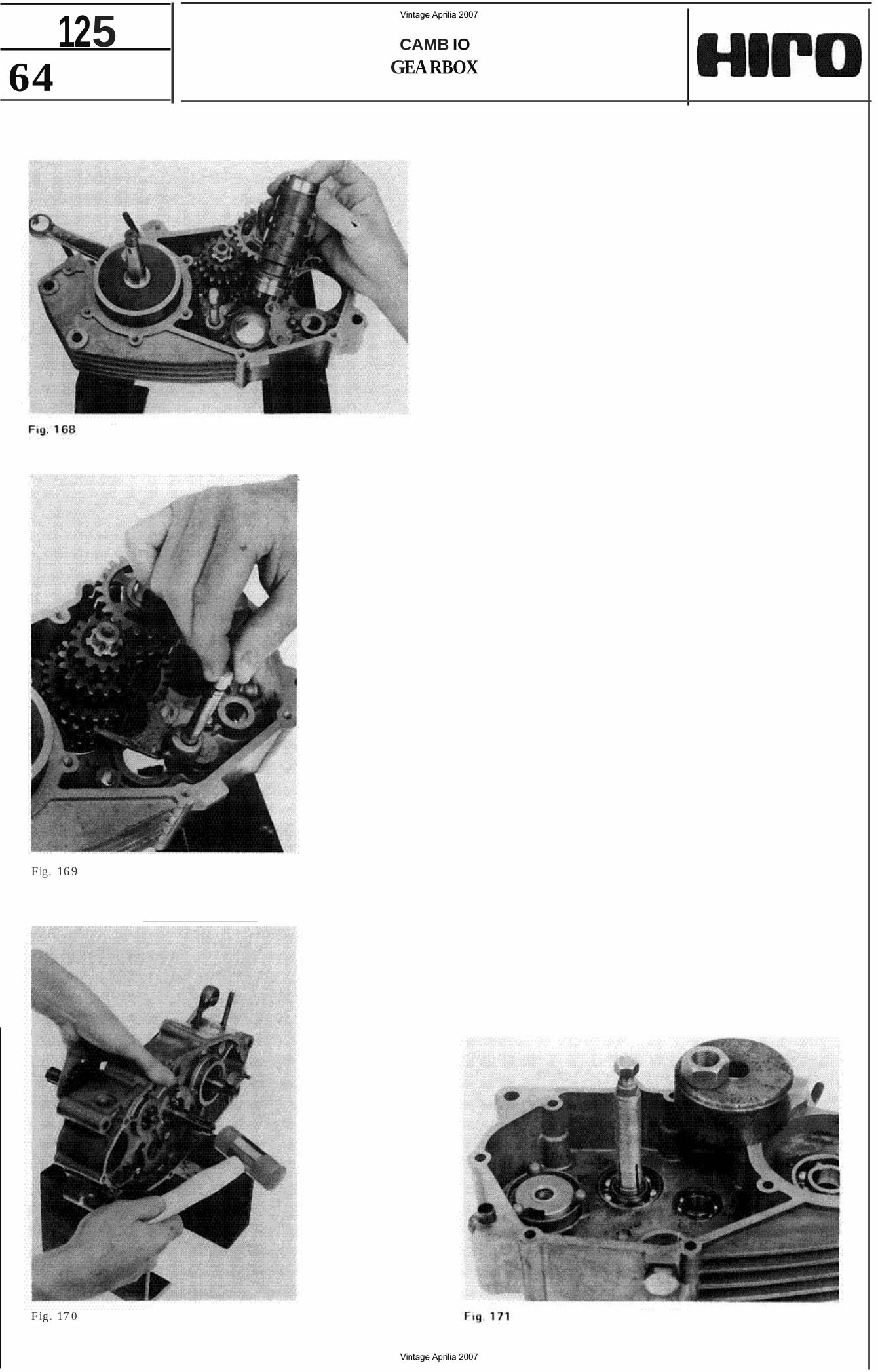
64 125 CAMB IO
GEA RBOX
Fig. 16 9
F ig. 17 0
Vintage Aprilia 2007
Vintage Aprilia 2007
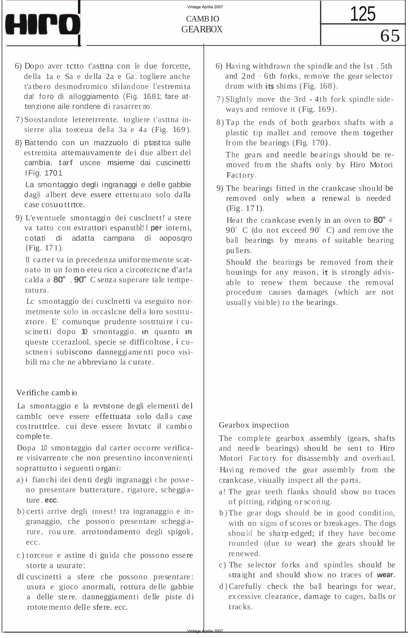
65 125CAMB IO
GEARBOX
6) Dopo aver tctto t'asttna con Ie due forcette, della 1a e Sa e della 2a e Ga . togliere anche t'a tbe ro desmod romico sfi landone l'estremi ta da! fo ro di alloggiamento (Fig. 1681; fare attenzione aile rondene d i rasarrer no.
7) Soostandote Ieteretrrente. togliere t'asttna insierre alia toeceua de lla 3a e 4a (Fig. 169 ).
8) Bat tendo con un mazzuolo di ptast tca sulle es t remita attemauvamen te de i due albert del cambia. tarf uscee msieme dai cuscinetti IFig. 1701.
La smontaggio degli ingranaggi e dell e gabbie dagli a lbert deve essere ettettu ato solo dalla case cosuu ttrtce.
9) L'eve ntuele smontaggi o dei cusclnet t! a stere va ta tto con estrattori espanstbl! l interni, cotati di adat ta campana di aoposqro {Fig. 171).
II carter va in precedenza uniformemente scatoato in un fom o eteu rico a circoteztcne d'ar!acalda a . C senza superare ta le temperatu ra.Lc smontaggio de i cusclnet ti va eseguito normetmen te solo in occaslcne dell a Ioro sostttuztore. E' comunque prudente sostttui re i cuscine tti dopo 10 srnontaggio. quanto queste ccerazlool. specie se difficoltose , cusctnen i subiscono danneggiame nti poco vis ibili rna che ne abbreviano la c ura te.
Verifiche camb io
La smontaggio e la revtstone de gli ele rnent i de l camblc oeve essere effe ttuata solo da ll a case cos trut trlce. cui deve essere lnvtatc iI cambi o comple te.
Dopa 10 smon taggio dal carter occorre verificare visivarren te che non presen tino inconvenienti soprattu tto seguenti o rgani:
a) fianchi dei den ti degli ingranaggi che posse no presentare buttera ture , rigature, scheggiature .
b) certi arrive degli tnnest ! t ra ingranaggio e ingranaggio, che posson o presentare scheggi arure, rou ure. arro tondamento degli spigoli , ecc.
c ) torceue e as tine d i gu ida che possono essere storte a usurate:
dl cuscinetti a sfere che possono presentare : usura e gioco anormali, rottura de lle gabbie a delle ste re. danneggiament i delle piste d i rotote mento delle sfere. ecc.
6) Havi ng withdrawn the spindle and the lst . 5th and 2nd · 6 th forks , remove the gear selector drum with shims (Fig. 168).
7) Slightly move the 3rd - 4th fork spindle sideways and remove it (Fig. 169).
8) Tap the ends of both gearbox shaf ts with a plas tic tip malle t and remove them together from the bearings (Fig. 170) .
The gears and needle bearings should be removed fro m the shafts only by Hiro Motori Factory.
9) The bearings fitted in the crankcase should be rem oved only when a renewal is needed (Fig . 171).
Heat the crankcase even ly in an oven to 900 C (do not exceed 900 C) and rem ove the ba ll bearings by means o f suitable bearing pu lle rs.
Should the bearings be removed from their housings for any reason , is st rongly advisab le to renew them because the removal procedu re cau ses da mages (which are not usuall y visi ble) to the bearings.
Gearbox inspection
The comp le te gearbox assembly (gears, shafts and need le bearings) shou ld be sen t to Hiro Motori Fac to ry for disassembly and overh au l.
Havi ng removed the gear assemb ly from the crankcase, visually inspect all the parts .
a! The gear teeth flanks should show no t races of pitting, ridging o r scori ng.
b ) The gear dogs should be in good condit ion, with no signs o f scores or b reakages. The dogs shou ld be sha rp-edged; if they have become rounded (due to wear) the gears should be renewed.
c) The selector fo rks and spind les should be stra ight and should show no t races of
d}Carefully check the ba ll bearings for wear, ex cessive clearance , damage to cages, ba lls or t racks.
Vintage Aprilia 2007
Vintage Aprilia 2007
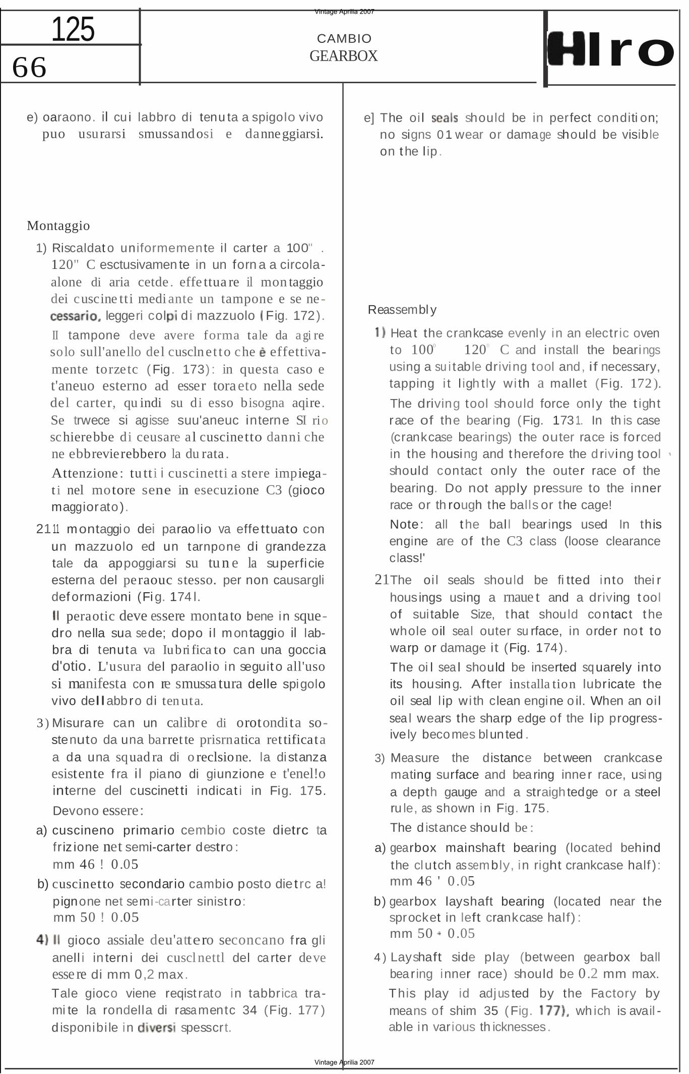
66 125 CAMBIO
GEARBOX Iro e) oaraono. il cu i labbro di tenu ta a spigolo vivo
puo usurarsi smussandosi e danneggiarsi.
Montaggio
1) Riscaldat o uniformemente il car ter a 100" . 120" C esctusivamen te in un forn a a circolaalone di aria cetde . effe ttua re il mon taggio dei cuscine tti medi ante un tampone e se ne
leggeri col d i mazzuolo Fig. 172).
II tampone deve avere forma tale da a gi re solo sull'anello del cusclnet to che effettivamente torzetc ( Fig. 173) : in questa caso e t'aneuo esterno ad esser toraeto nella sede del carter, qu indi su di esso bisogna aqire. Se trwece si agisse suu'aneuc interne SI rio schierebbe di ceusare al cuscinetto danni che ne ebbrevierebbero la du rata .
Attenzione : tu tti i cuscinetti a stere impiegat i nel motore sene in esecuzione C3 (gioco maggiorato ).
21 11 m ontaggio dei parao lio va effettuato con un mazzuolo ed un tarnpone di grandezza tale da appoggiarsi su tu n e la superficie esterna del peraouc stesso. per non causargli def ormazioni (Fi g. 174 l.
peraotic deve essere montato bene in squedro nella sua sede; dopo i l m ontaggio il labbra di tenuta va Iubri fica to can una goccia d'otio. L'usura del paraol io in seguit o all'uso si manifesta con re smussa tura delle spigolo vivo dellabbro di tenuta.
3 ) Misurare can un calibre di orotondita sostenuto da una barret te prisrnatica ret tificata a da una squad ra di o reclsione. la distanza esistente f ra i l piano di giunzione e t'enel!o interne del cuscinet ti indicat i in Fig. 175.
Devono essere: a) cuscineno primario cembio coste dietrc ta
fr iz ione net semi-carter destro : mm 46 ! 0 .05
b) cuscinetto secondario cambio posto die t rc a! pignone net semi-carter sinist ro: mm 50 ! 0 .05
gioco assiale deu'attero seconcano f ra gli anell i in tern i dei cusclnettl del ca rter deve esse re di mm 0,2 max.
Tale gioco viene reqist rato in tabbrica trami te la rondella di rasa mentc 34 (Fig. 177 ) d isponibi le in spesscrt.
e] The oi l should be in perfect conditi on; no signs 0 1 wear or damage should be visible on t he l ip .
Reassembl y
Hea t the crankcase evenly in an electr ic oven to 1000 1200 C and install the bearings using a su i table driving tool and, if necessary, tapping i t l igh tly wi th a mallet (Fig. 172 ).
The driving tool should force only the t ight race of the bearing (Fig. 1731. In th is case (crankcase bearings) the outer race is forced in the housing and t herefore the d riving tool should contact only the outer race of the bearing. Do not apply pressure to the inner race or th rough the balls or the cage!
Note: all t he bal l bearings used In this engine are of the C3 class (loose clearance class!'
21The oi l seals should be fi tted into thei r housings using a rnaue t and a driving t ool of sui table Size, t hat should contact t he whole oil seal outer su rface, in order no t to warp or damage it (Fig. 174).
The oi l sea l should be inserted sq uarely into its housin g. After installa tion lubricate the oil seal l ip wi th clean engine o il. When an oi l sea l wears the sharp edge of the l ip progressively beco mes blun ted .
3) Measure the distance bet ween crankcase mating surface and bea ring inner race, usi ng a depth gauge and a straigh tedge or a steel ru le, as shown in Fig. 175.
The d istance shou ld be :
a) gearbox mainshaft bearing (located behind the clutch assembly, in right crankcase half ): mm 46 ' 0 .05
b) gearbox layshaft bearing (located near the sprocket in left crankcase half) : mm 50 0 .05
4 ) Layshaft side play (between gearbox ball bea r ing inner race) should be 0.2 mm max.
This play id adjus ted by the Factory by means of shim 35 ( Fig. wh ich is avail able in various th icknesses.
Vintage Aprilia 2007
Vintage Aprilia 2007
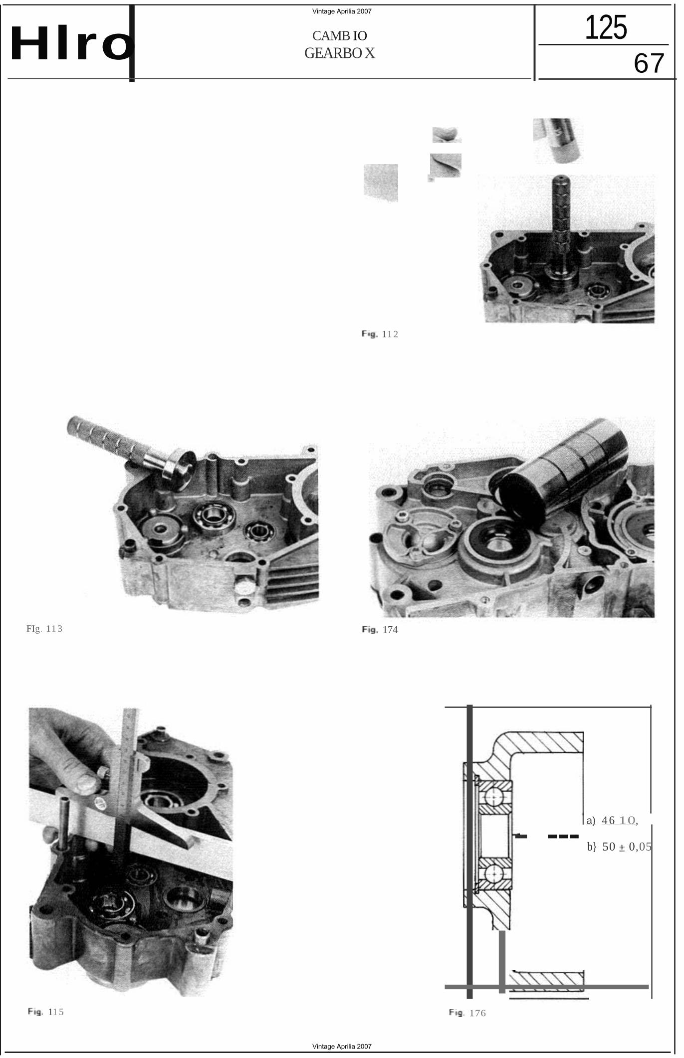
67 125CAMB IO
GEARBO XHlro
11 2
FIg. 11 3 174
- a) 4 6 10, --- b} 50 0,05
11 5 176
Vintage Aprilia 2007
Vintage Aprilia 2007
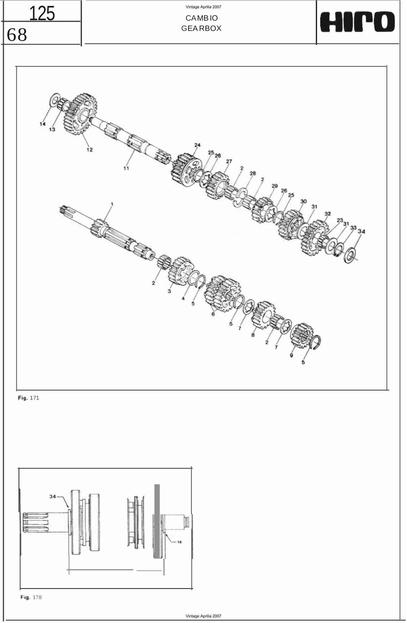
68 125 CAMB IO
GEA RBOX
171
178
Vintage Aprilia 2007
Vintage Aprilia 2007
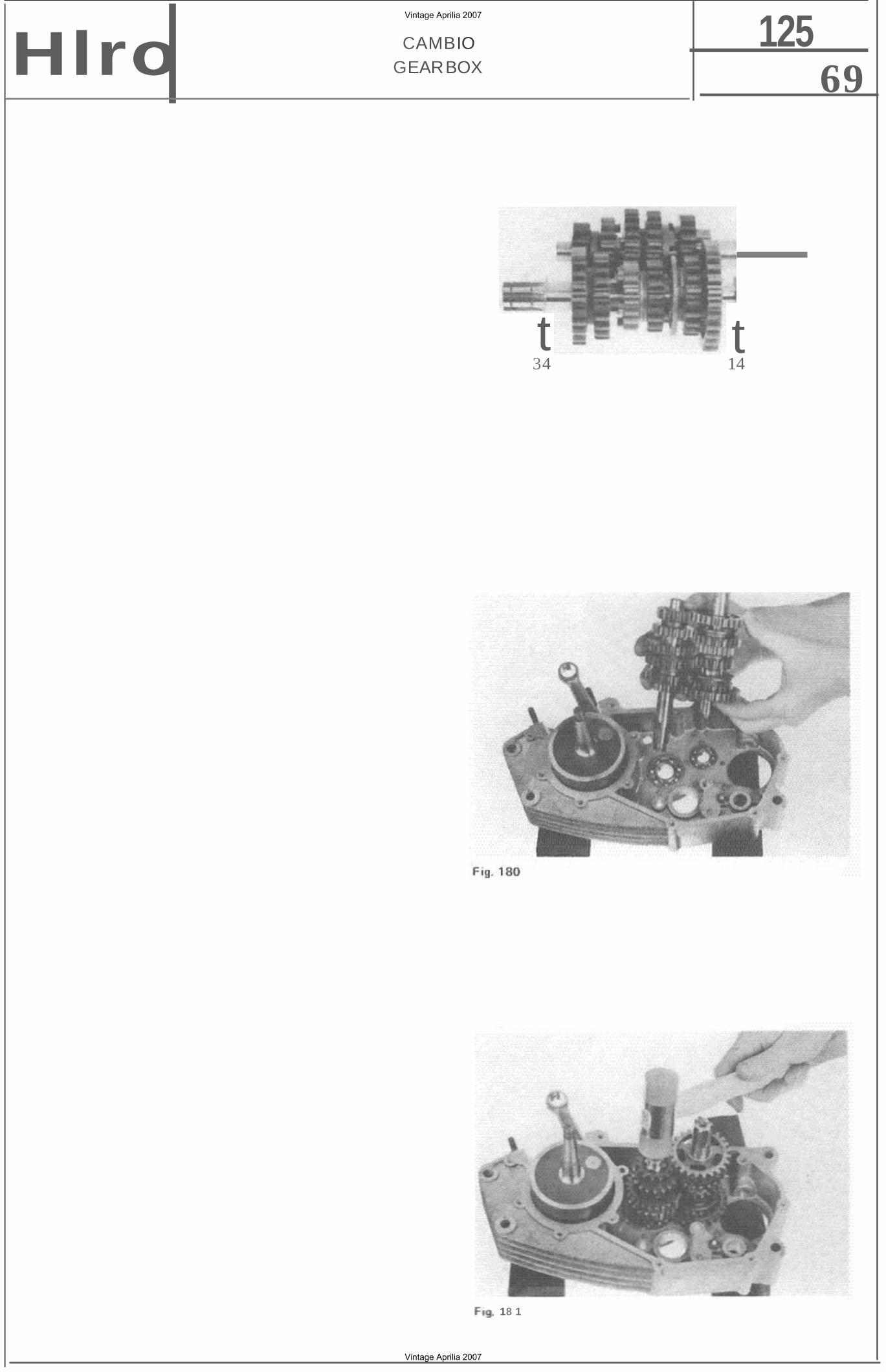
69 125CAMBIO
GEARBOXHlro
t t34 14
Fog 1
18 1
Vintage Aprilia 2007
Vintage Aprilia 2007
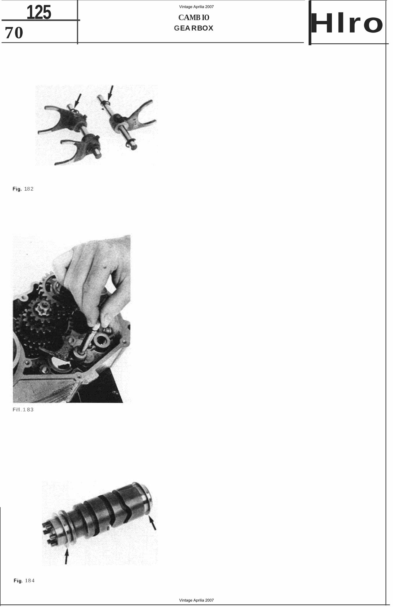
70 125 CAMB IO
GEA RBOX Hlro
182
Fi!l.1 83
18 4
Vintage Aprilia 2007
Vintage Aprilia 2007
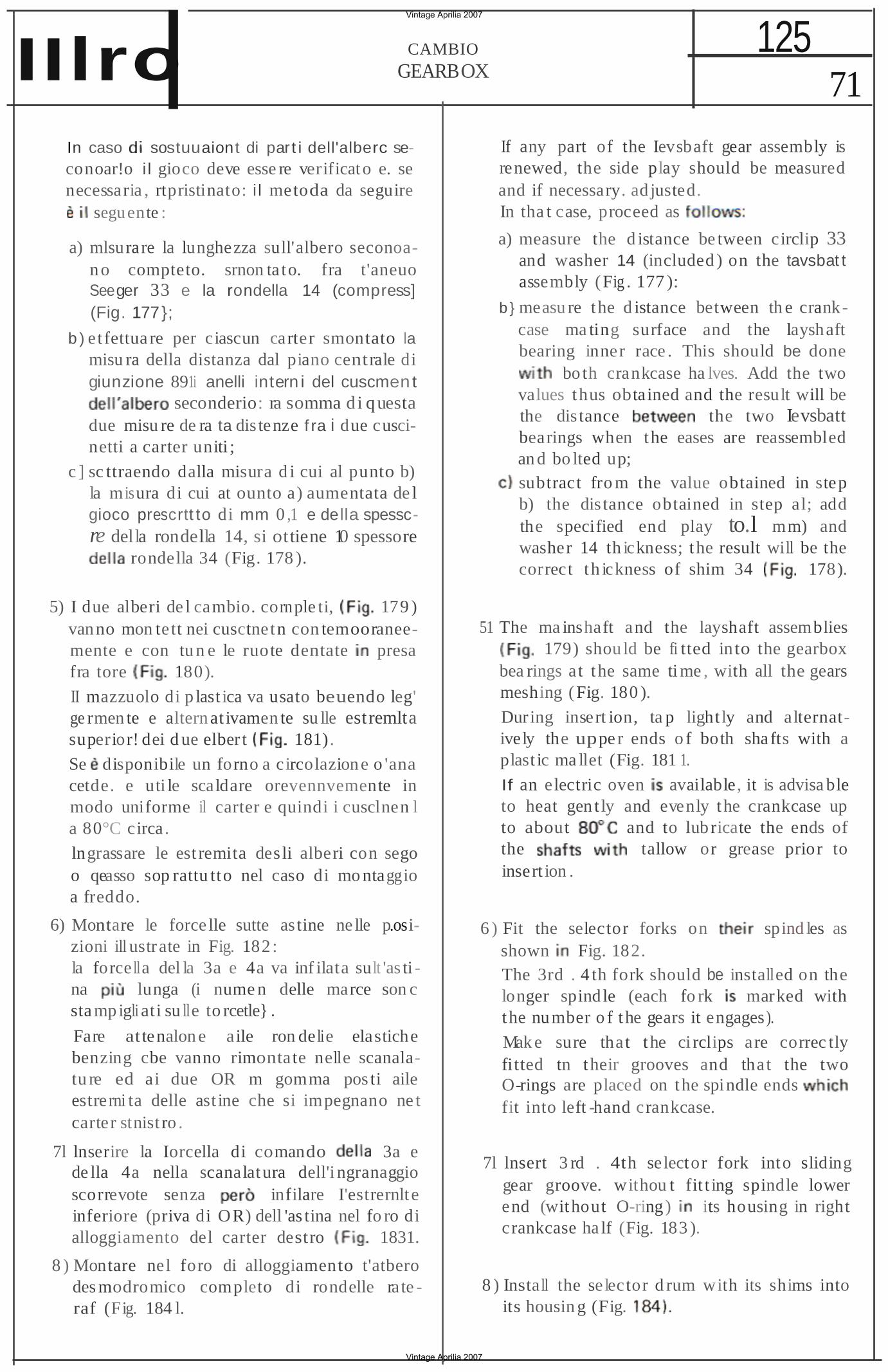
71 125CAMBIO
GEARBOXIIlro In caso sostuuaiont di par t i dell'alberc seconoar!o i l gioco deve esse re verificato e. se necessaria , rtpristinato: i l metoda da seguire
seguente :
a) mlsurare la lunghezza sull'albero seconoan o compteto. srnon ta to. fra t'aneuo Seeger 33 e la rondella 14 (compress] (Fig. 177};
b ) etfettua re per ciascun carter smontato la misu ra della distanza dal piano centrale di giunzione 891i anelli intern i del cuscmen t
seconderio: ra somma di q uesta due misu re de ra ta dis tenze f ra i due cuscinetti a carter uniti ;
c ] sc ttraendo dalla misura d i cui al punto b) la misura di cui at ounto a) aumentata de l gioco prescrtt to di mm 0 ,1 e della spesscre della rondella 14, si ottiene 10 spessore
rondella 34 (Fig. 178 ).
5) I due alberi de l cambio. cornple ti, 179 ) vanno mon tett nei cusctnet n con temooraneemente e con tu n e le ruote dentate presa fra tore 180).
II mazzuolo di p last ica va usato beuendo leg' ge rmen te e altern at ivamen te su lle estremlta superior! dei d ue elber t 181).
Se disponibile un forno a circolazione o 'ana cetde. e uti le scaldare orevennvemente in modo uniforme il carter e quindi i cusclnen l a 80°C circa.
lngrassare le est remita des li alberi con sego o qeasso sop rattu tto nel caso di mo ntaggio a freddo.
6) Montare le force lle sutte as tine ne lle p.osizioni ill ustrate in Fig. 182 : la force lla del la 3a e 4a va inf ilata sult 'as ti na lunga (i nume n delle marce son c sta mp igli ati su lle to rcetle} .
Fare attenalon e aile ron delie elastiche benzing cbe vanno rimontate nelle scanalatu re ed ai due OR m gomma pos ti aile estrerni ta delle ast ine che si impegnano ne t carter stnist ro .
7l lnserire la Iorcella di comando 3a e de lla 4a nella scanalatura dell'i ngranaggio scorrevote senza infilare I'estrernlt e inferiore (priva di OR) dell 'as tina nel fo ro di alloggiamento del carter destro 1831.
8 ) Montare nel foro di alloggiamento t'atbero des modromico completo di rondelle ra te raf (Fig. 184 l.
If any part of the Ievsbaft gear assembly is renewed, the side play should be measured and if necessary. ad justed. In tha t case, proceed as
a) measure the d istance be tween circlip 33 and washer 14 (included ) on the tavsbat t assembly (Fig . 177 ):
b } measu re the d istance between th e crankcase ma ting surface and the layshaft bearing inner race . This should be done
bo th crankcase ha lves. Add the two values thus obtained and the result will be the dis tance the two Ievsbatt bearings when the eases are reassembled an d bo lted up; subtract fro m the value obtained in step b) the dis tance obtained in step al; add the specified end play to.l mm) and washer 14 th ickness; the result will be the correct th ickness of shim 34 178).
51 The ma inshaft and the layshaft assemblies 179) shou ld be fi tted in to the gearbox
bea rings at the same ti me , with all the gears meshing ( Fig. 180 ).
During insert ion, ta p light ly and alternatively the uppe r ends o f both sha fts with a plast ic ma llet (Fig. 181 1.
If an electric oven available, it is advisa ble to heat gen t ly and evenly the crankcase up to about and to lub ricate the ends of the tallow or grease prior to insert ion .
6 ) Fit the selector forks on spind les as shown Fig. 182. The 3rd . 4 th fork should be installed on the longer spind le (each fo rk marked with the number o f the gears it engages).
Mak e sure that the ci rclips are correc tly fitted tn their grooves and that the two O-rings are placed on the spi ndle ends fit into left -hand crankcase.
7l lnsert 3 rd . 4th selector fork into sliding gear groove. withou t fit t ing spindle lower end (without O-ring) its housing in right crankcase ha lf (Fig. 183 ).
8 ) Insta ll the selector d rum with its shims into its housin g (Fig.
Vintage Aprilia 2007
Vintage Aprilia 2007
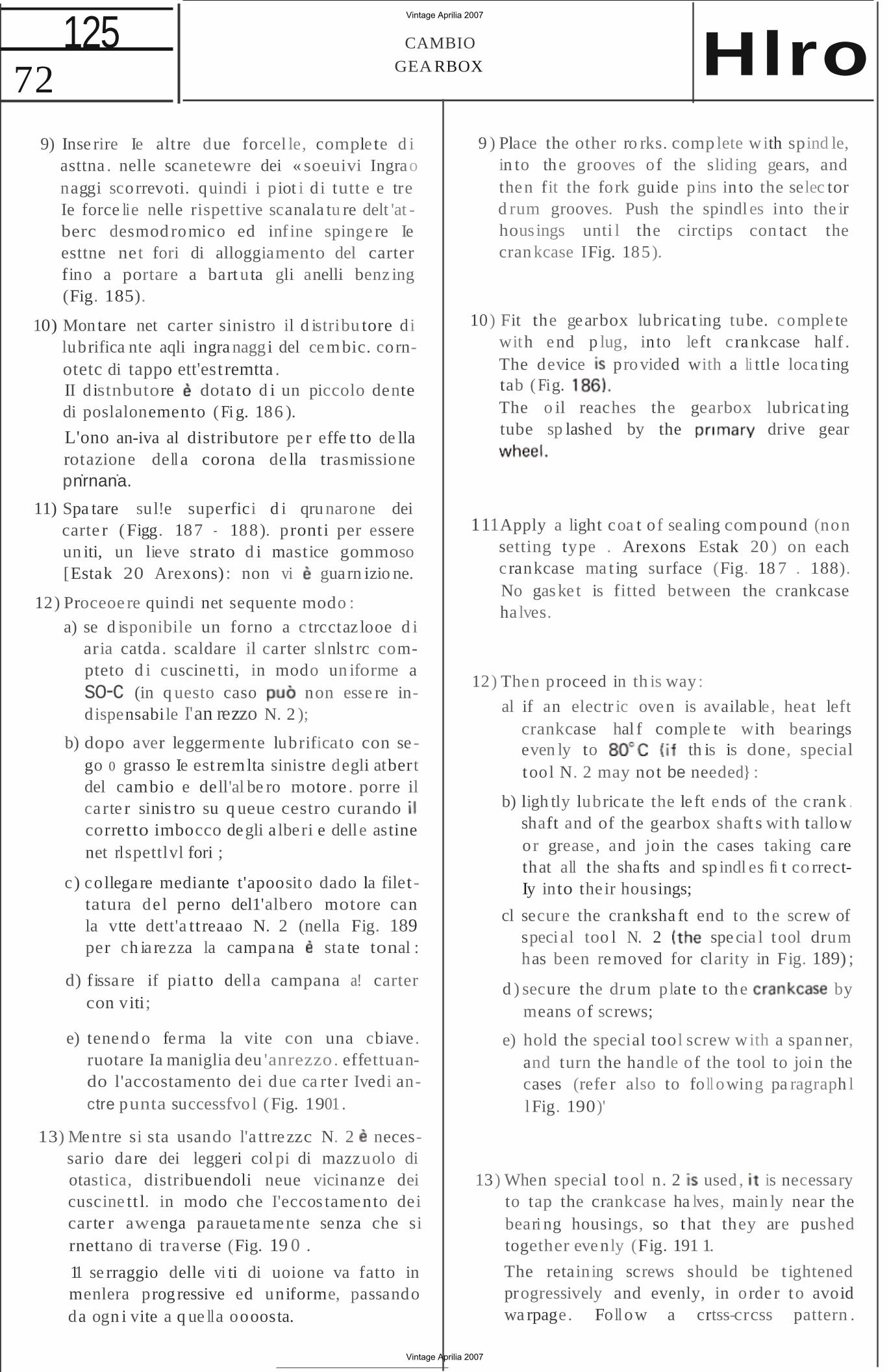
72 125 CAMBIO
GEA RBOX Hlro 9) Inse rire Ie altre due forcel le, comple te d i
asttna . nelle scanetewre dei « soeuivi Ingrao naggi scorrevoti. quindi i piot i d i tutte e tre Ie force lie nelle rispettive scanala tu re delt 'at berc desmod romico ed inf ine spinge re Ie esttne net fori di alloggiamento del carter fino a portare a bart uta gli anelli benz ing (Fig. 185).
10) Mon tare net carter sinistro il d istribu tore di lubrifica nte aqli ingra naggi del cem bic. cornotetc di tappo ett'est remtta . II d istnbutore dotato d i un piccolo dente di poslalonemento ( Fi g. 186 ).
L'ono an-iva al distributore pe r effe tto de lla rotazione dell a corona de lla trasmissione
. . pnrnana.
11) Spa tare sul!e superfici d i qru narone dei carte r ( Figg. 187 188). pronti per essere un iti, un lieve strato d i mastice gommoso [Estak 20 Arexons) : non vi guarn izio ne.
12) Proceoe re quindi net sequente modo :
a) se d isponibile un forno a c trcctaz looe d i aria catda . scaldare il carter slnlst rc compteto d i cuscine tti, in modo un iforme a so-c (in q uesto caso non esse re indispensabile I'an rezzo N. 2 );
b) dopo aver leggermente lubrificato con se go 0 grasso Ie est remlta sinistre degli atbert del cambio e dell'al be ro motore . porre il ca rte r sinis tro su q ueue cestro curando corretto imbocco degli a lberi e delle astine net rlspettlvl fori ;
c ) collega re mediante t'apoosito dado la filet tatura de l perno del1'albero motore can la vtte dett'a tt reaao N. 2 (nella Fig. 189 per ch ia rezza la campa na sta te tonal :
d) fissa re if piat to della campana a! carter con viti;
e) tenend o fe rma la vite con una cbiave. ruotare Ia maniglia deu 'anrezzo. effettuando l'accostamento dei due ca rte r Ivedi anctre punta successfvo l ( Fig. 1901 .
13) Mentre si sta usando l'a tt rezzc N. 2 necessario dare dei leggeri col pi di mazzuolo di otastica, distribuendoli neue vicinanze dei cuscine tt l. in modo che I'eccos tamento dei carte r awenga pa rauetamente senza che si rnettano di traverse (Fig. 19 0 .
11 se rraggio delle vi ti di uoione va fatto in menlera progressive ed uniforme, passando da ogn i vite a q ue lla oooosta.
9 ) Place the other ro rks. comp lete with spind le, in to the grooves of the sliding gears, and then fit the fork guide pins into the selec tor d rum grooves. Push the spindl es into the ir housings unti l the circtips con tact the cran kcase IFig. 185).
10) Fit the gearbox lubricat ing tube. comple te with end p lug, in to left c ra nkcase half . The device provided with a li ttle loca ting tab ( Fig. The o il reaches the gearbox lubricat ing tube sp lashed by the drive gear
111Apply a light coa t of sealing com pound (non setting type . Arexons Estak 20 ) on each c rankcase ma t ing surface (Fig. 18 7 . 188). No gas ke t is fitted between the crankcase ha lves.
12) Then proceed in th is way :
al if an electr ic oven is available , heat left crankcase hal f comple te with bearings even ly to th is is done, special tool N. 2 may not be needed} :
b) ligh tly lubrica te the le ft ends of the c rank . shaft and of the gearbox shaft s with tallow or grease , and jo in t he cases taking ca re that all the sha fts and sp indl es fi t co rrectIy into the ir housings;
cl secure the cranksha ft end to the screw of speci al too l N. 2 spe cia l tool drum has been removed for clarity in Fig. 189) ;
d ) secure the drum plate to the by means of screws;
e) hold the special tool screw with a span ner, and turn the handle of the tool to joi n the cases (refe r also to fo ll owing pa ragraph l l Fig. 190)'
13) When special tool n. 2 used , is necessary to tap the crankcase ha lves, main ly near the beari ng housings, so t hat they are pushed together eve nly (Fig. 191 1.
The retaining screws should be t ightened progressively and evenly, in orde r to avoid wa rpage. Fo ll ow a crtss-crcss pattern .
Vintage Aprilia 2007
Vintage Aprilia 2007
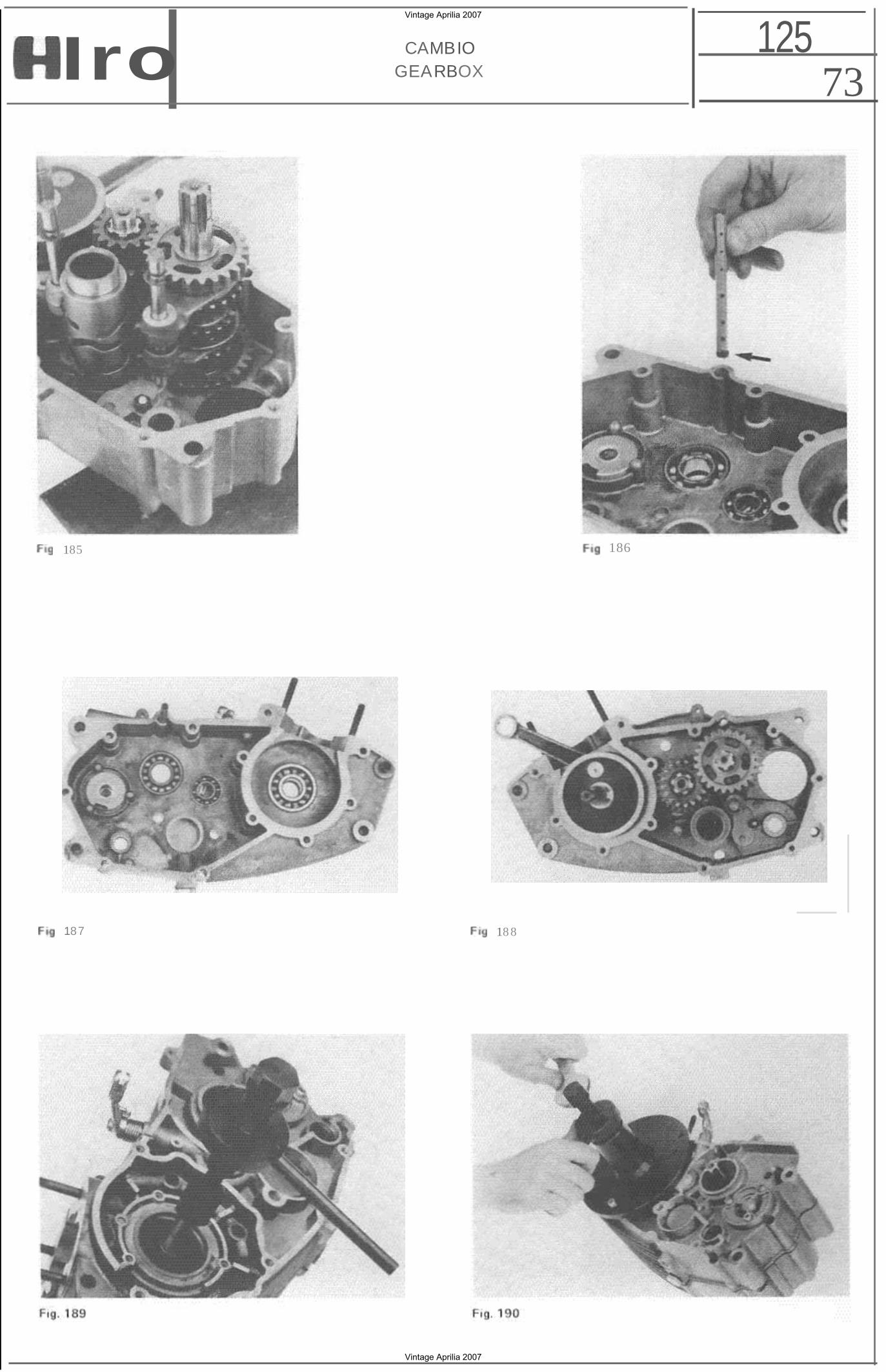
73 125CAMBIO
GEARBOXIro
185 186
187 18 8
Vintage Aprilia 2007
Vintage Aprilia 2007
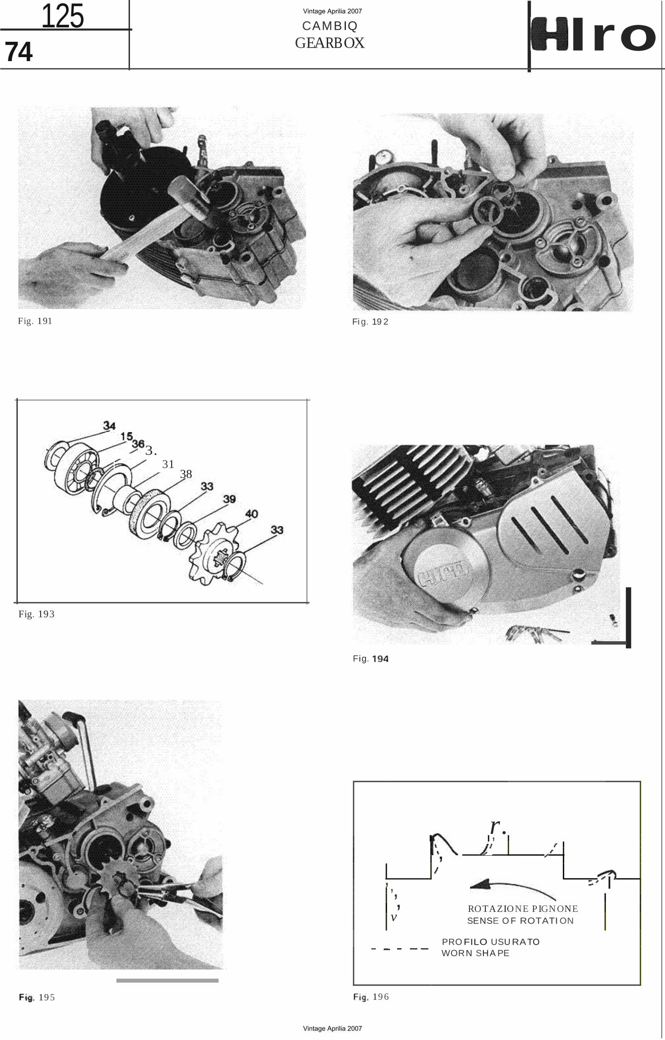
- - --
74 125 CAMBIQ
GEARBOX Iro
Fig. 191 Fi g. 19 2
3. 31
38
e-,
Fig.
Fig. 193
r. ,
I RO TAZIO NE P IGN ONE SENSE O F ROTATI ON
PRO FILO USU RATO WORN SHA PE
, ,,, , v
19 5 19 6
Vintage Aprilia 2007
Vintage Aprilia 2007
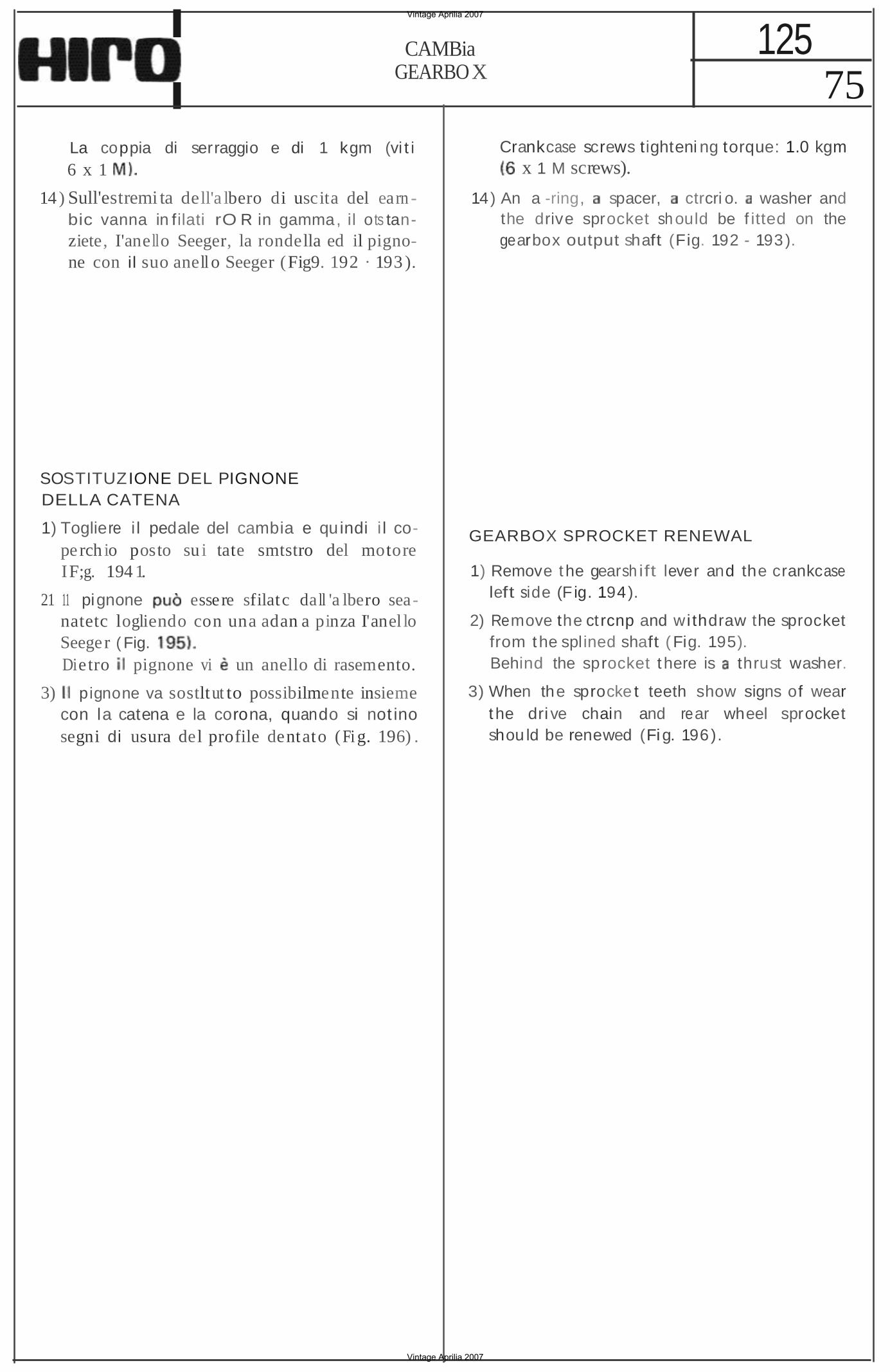
75 125CAMBia
GEARBOX
La coppia di serraggio e di 1 kgm (vi t i 6 x 1
14 ) Sull'estremi ta dell'a lbero di uscita del earn bic vanna in filati rO R in gamma, il ots tanziete, I'anello Seeger, la rondella ed il pignone con il suo anell o Seeger (Fig9. 192 · 193 ).
SOSTITUZIONE DEL PIGNONE DELLA CATENA
1) Togliere i l pedale del cambia e quindi i l coperch io posto su i tate smtstro del motore IF;g. 194 1.
21 11 pignone essere sfilatc da ll 'a lbero seanatetc logliendo con una adan a pinza I'anel lo Seeger ( Fig. Dietro pignone vi un anello di rasemento.
3) pignone va sostlt ut to possibilmente insieme con la catena e la corona, quando si not ino segni di usura del profile dentato (Fi g. 196) .
Crankcase screws tighteni ng torque: 1.0 kgm x 1 M screws).
14) An a -ring, spacer, ctrcri o. washer and the drive sprocket sh ould be f itted on the gearbox output shaft (Fig. 192 - 193).
GEARBOX SPROCKET RENEWAL
1) Remove the gearsh ift lever and the crankcase left side (F ig. 194).
2) Remove the ct rcnp and wi thdraw the sprocket from the splined shaft (Fig. 195). Behind the sprocket t here is thrust washer.
3) When the sprocke t teeth show signs of wear the dri ve chain and rear wheel sprocket shou ld be renewed (Fig. 196).
Vintage Aprilia 2007
Vintage Aprilia 2007