VALVOLE DI CONTROLLO E INTERCETTAZIONE, SISTEMI DI ... · valvole di controllo e intercettazione,...
34
VALVOLE DI CONTROLLO E INTERCETTAZIONE, SISTEMI DI AZIONAMENTO, DISCHI DI ROTTURA E DISPOSITIVI DI SICUREZZA UTILIZZATI NELL’INDUSTRIA DI PROCESSO Milano, 18 Aprile 2018 Auditorio TECNIMONT
Transcript of VALVOLE DI CONTROLLO E INTERCETTAZIONE, SISTEMI DI ... · valvole di controllo e intercettazione,...
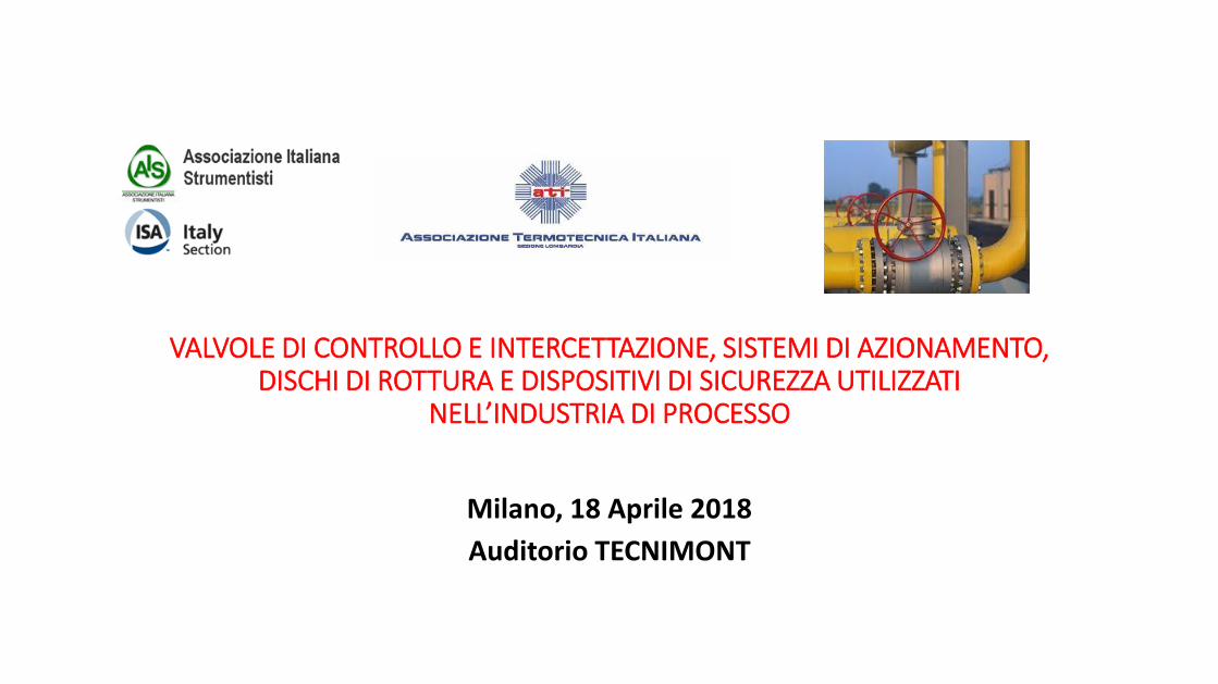
VALVOLE DI CONTROLLO E INTERCETTAZIONE, SISTEMI DI AZIONAMENTO, DISCHI DI ROTTURA E DISPOSITIVI DI SICUREZZA UTILIZZATI
NELL’INDUSTRIA DI PROCESSO
Milano, 18 Aprile 2018
Auditorio TECNIMONT
© C
op
yri
gh
t K
SB
Aktie
ng
ese
llsch
aft
20
14
Severe Service Solutions for Oil & Gas Sector
© Copyright KSB Aktiengesellschaft 2013
Typical Severe Service Application Challenges &
Engineered Control Valve Solutions
© Copyright KSB SE & Co. KGaA 2018
Presented by Mr. Biju Simon, KSB MIL
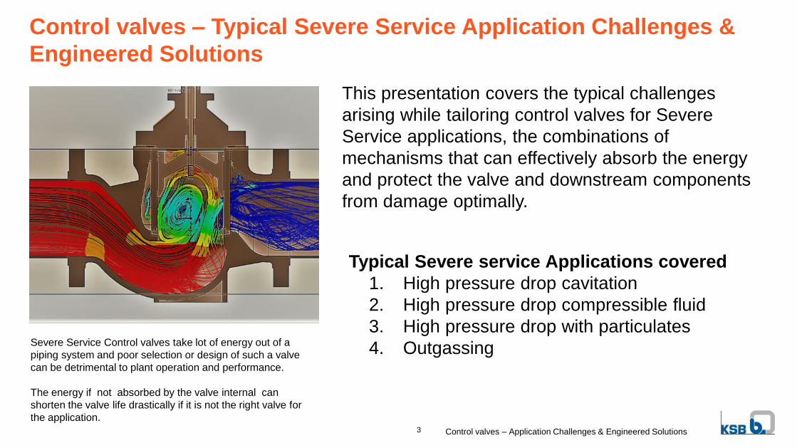
This presentation covers the typical challenges
arising while tailoring control valves for Severe
Service applications, the combinations of
mechanisms that can effectively absorb the energy
and protect the valve and downstream components
from damage optimally.
3 Control valves – Application Challenges & Engineered Solutions
Severe Service Control valves take lot of energy out of a
piping system and poor selection or design of such a valve
can be detrimental to plant operation and performance.
The energy if not absorbed by the valve internal can
shorten the valve life drastically if it is not the right valve for
the application.
Control valves – Typical Severe Service Application Challenges &
Engineered Solutions
Typical Severe service Applications covered
1. High pressure drop cavitation
2. High pressure drop compressible fluid
3. High pressure drop with particulates
4. Outgassing
Control valves – Application Challenges & Engineered Solutions
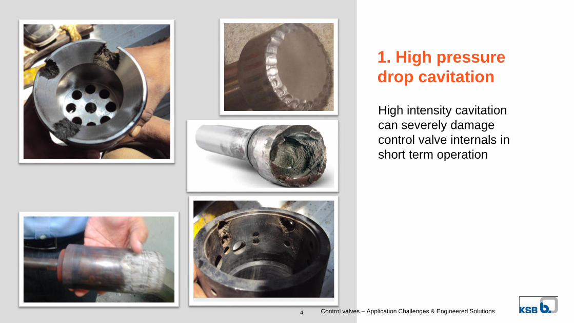
1. High pressure
drop cavitation
4
High intensity cavitation
can severely damage
control valve internals in
short term operation
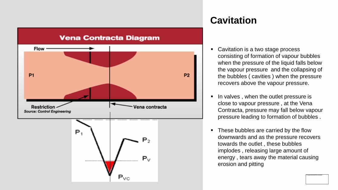
Cavitation
Cavitation is a two stage process
consisting of formation of vapour bubbles
when the pressure of the liquid falls below
the vapour pressure and the collapsing of
the bubbles ( cavities ) when the pressure
recovers above the vapour pressure.
In valves , when the outlet pressure is
close to vapour pressure , at the Vena
Contracta, pressure may fall below vapour
pressure leading to formation of bubbles .
These bubbles are carried by the flow
downwards and as the pressure recovers
towards the outlet , these bubbles
implodes , releasing large amount of
energy , tears away the material causing
erosion and pitting
© C
op
yri
gh
t K
SB
Aktie
ng
ese
llsch
aft
20
14
Control valves – Application Challenges & Engineered Solutions
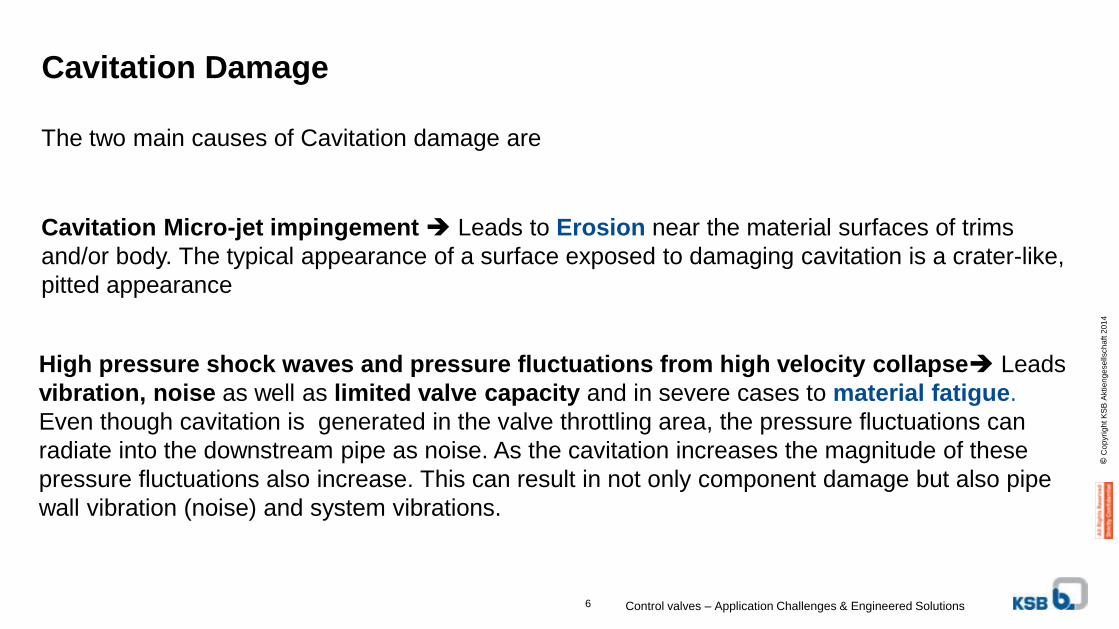
The two main causes of Cavitation damage are
Cavitation Micro-jet impingement Leads to Erosion near the material surfaces of trims
and/or body. The typical appearance of a surface exposed to damaging cavitation is a crater-like,
pitted appearance
Cavitation Damage
6
High pressure shock waves and pressure fluctuations from high velocity collapse Leads
vibration, noise as well as limited valve capacity and in severe cases to material fatigue.
Even though cavitation is generated in the valve throttling area, the pressure fluctuations can
radiate into the downstream pipe as noise. As the cavitation increases the magnitude of these
pressure fluctuations also increase. This can result in not only component damage but also pipe
wall vibration (noise) and system vibrations.
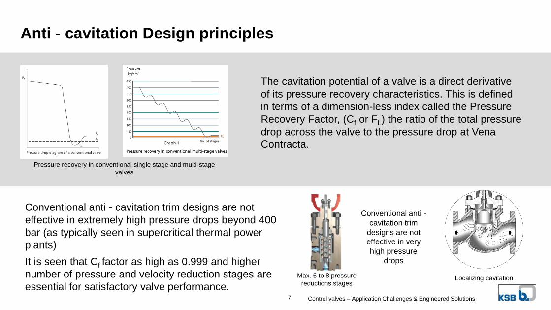
Anti - cavitation Design principles
Pressure recovery in conventional single stage and multi-stage
valves
The cavitation potential of a valve is a direct derivative
of its pressure recovery characteristics. This is defined
in terms of a dimension-less index called the Pressure
Recovery Factor, (Cf or FL) the ratio of the total pressure
drop across the valve to the pressure drop at Vena
Contracta.
Conventional anti - cavitation trim designs are not
effective in extremely high pressure drops beyond 400
bar (as typically seen in supercritical thermal power
plants)
It is seen that Cf factor as high as 0.999 and higher
number of pressure and velocity reduction stages are
essential for satisfactory valve performance.Control valves – Application Challenges & Engineered Solutions7
Localizing cavitation Max. 6 to 8 pressure
reductions stages
Conventional anti -
cavitation trim
designs are not
effective in very
high pressure
drops
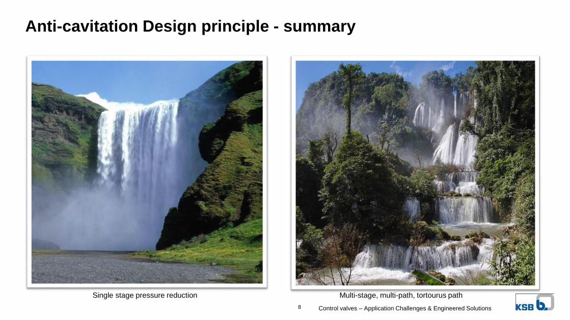
Anti-cavitation Design principle - summary
Single stage pressure reduction Multi-stage, multi-path, tortourus path
Control valves – Application Challenges & Engineered Solutions8
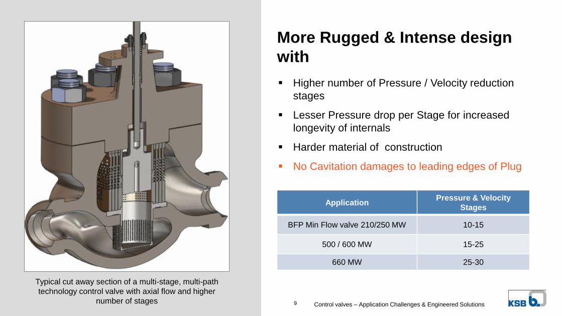
Higher number of Pressure / Velocity reduction
stages
Lesser Pressure drop per Stage for increased
longevity of internals
Harder material of construction
No Cavitation damages to leading edges of Plug
More Rugged & Intense design
with
ApplicationPressure & Velocity
Stages
BFP Min Flow valve 210/250 MW 10-15
500 / 600 MW 15-25
660 MW 25-30
Typical cut away section of a multi-stage, multi-path
technology control valve with axial flow and higher
number of stagesControl valves – Application Challenges & Engineered Solutions9
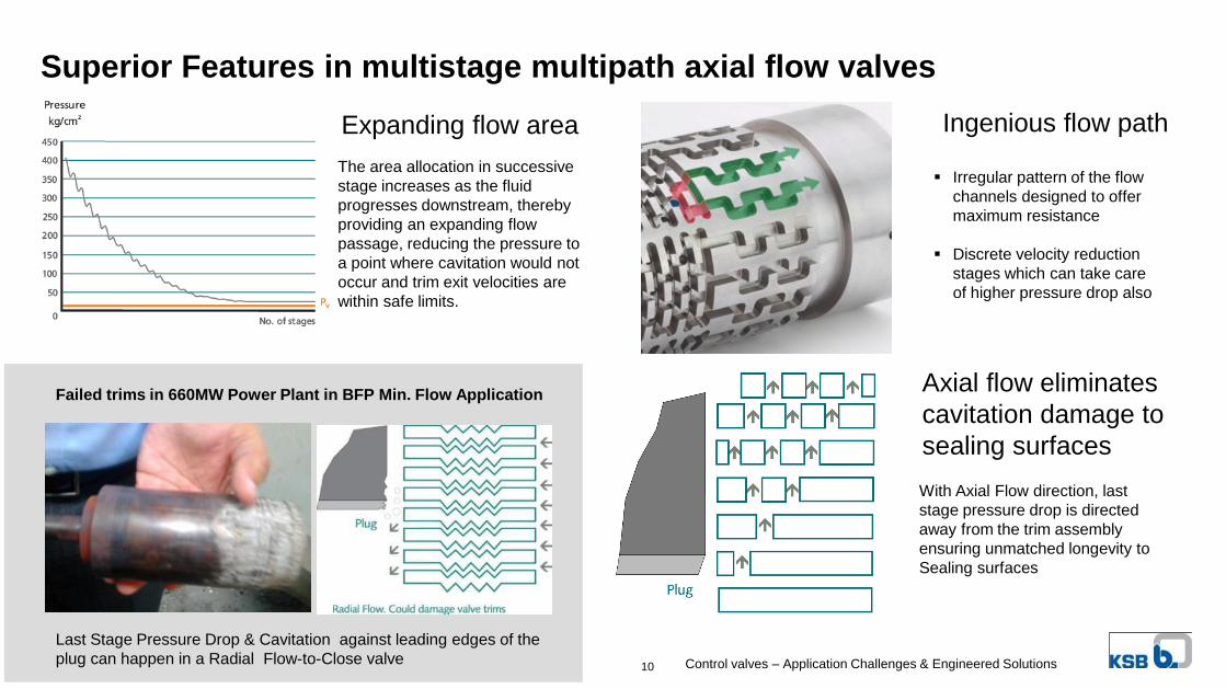
Superior Features in multistage multipath axial flow valves
With Axial Flow direction, last
stage pressure drop is directed
away from the trim assembly
ensuring unmatched longevity to
Sealing surfaces
Axial flow eliminates
cavitation damage to
sealing surfaces
Failed trims in 660MW Power Plant in BFP Min. Flow Application
Last Stage Pressure Drop & Cavitation against leading edges of the
plug can happen in a Radial Flow-to-Close valve Control valves – Application Challenges & Engineered Solutions10
Irregular pattern of the flow
channels designed to offer
maximum resistance
Discrete velocity reduction
stages which can take care
of higher pressure drop also
Ingenious flow path
The area allocation in successive
stage increases as the fluid
progresses downstream, thereby
providing an expanding flow
passage, reducing the pressure to
a point where cavitation would not
occur and trim exit velocities are
within safe limits.
Expanding flow area
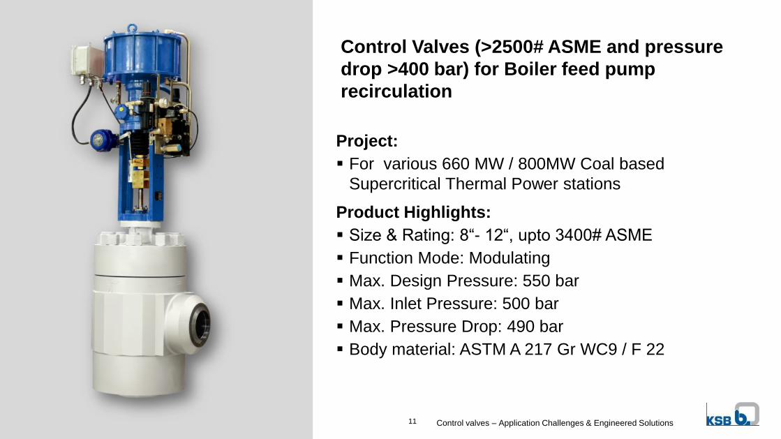
Control Valves (>2500# ASME and pressure
drop >400 bar) for Boiler feed pump
recirculation
Project:
For various 660 MW / 800MW Coal based
Supercritical Thermal Power stations
Product Highlights:
Size & Rating: 8“- 12“, upto 3400# ASME
Function Mode: Modulating
Max. Design Pressure: 550 bar
Max. Inlet Pressure: 500 bar
Max. Pressure Drop: 490 bar
Body material: ASTM A 217 Gr WC9 / F 22
Control valves – Application Challenges & Engineered Solutions11
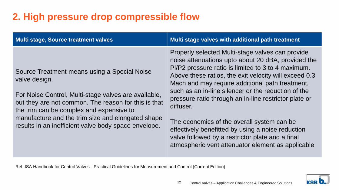
2. High pressure drop compressible flow
Multi stage, Source treatment valves Multi stage valves with additional path treatment
Source Treatment means using a Special Noise
valve design.
For Noise Control, Multi-stage valves are available,
but they are not common. The reason for this is that
the trim can be complex and expensive to
manufacture and the trim size and elongated shape
results in an inefficient valve body space envelope.
Properly selected Multi-stage valves can provide
noise attenuations upto about 20 dBA, provided the
Pl/P2 pressure ratio is limited to 3 to 4 maximum.
Above these ratios, the exit velocity will exceed 0.3
Mach and may require additional path treatment,
such as an in-line silencer or the reduction of the
pressure ratio through an in-line restrictor plate or
diffuser.
The economics of the overall system can be
effectively benefitted by using a noise reduction
valve followed by a restrictor plate and a final
atmospheric vent attenuator element as applicable
Ref. ISA Handbook for Control Valves - Practical Guidelines for Measurement and Control (Current Edition)
Control valves – Application Challenges & Engineered Solutions12
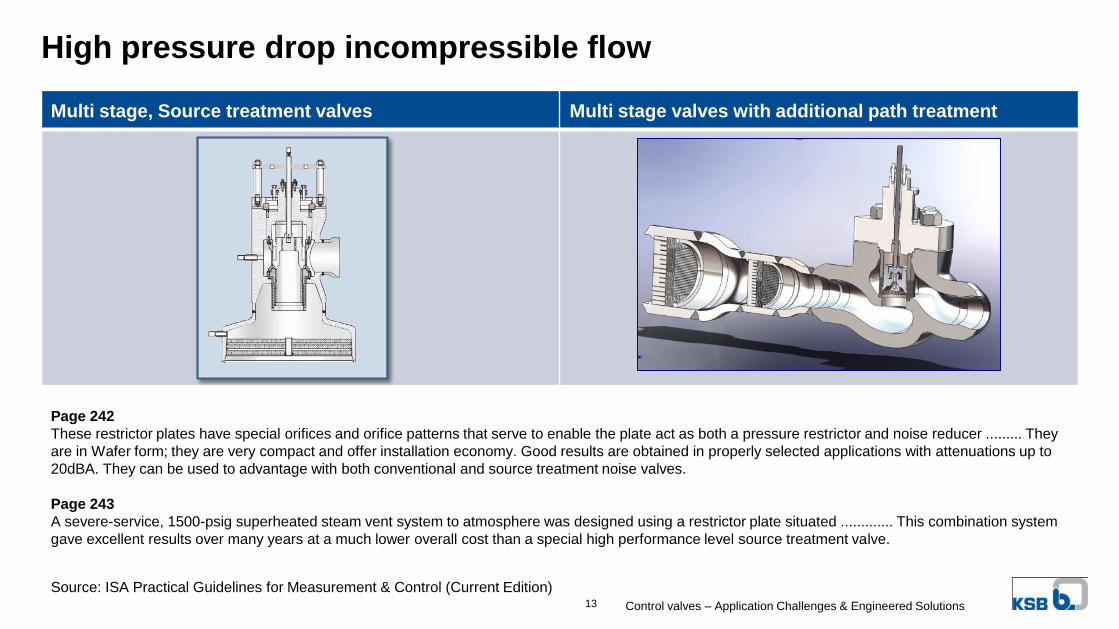
High pressure drop incompressible flow
Multi stage, Source treatment valves Multi stage valves with additional path treatment
Source: ISA Practical Guidelines for Measurement & Control (Current Edition)
Page 242
These restrictor plates have special orifices and orifice patterns that serve to enable the plate act as both a pressure restrictor and noise reducer ......... They
are in Wafer form; they are very compact and offer installation economy. Good results are obtained in properly selected applications with attenuations up to
20dBA. They can be used to advantage with both conventional and source treatment noise valves.
Page 243
A severe-service, 1500-psig superheated steam vent system to atmosphere was designed using a restrictor plate situated ............. This combination system
gave excellent results over many years at a much lower overall cost than a special high performance level source treatment valve.
Control valves – Application Challenges & Engineered Solutions13
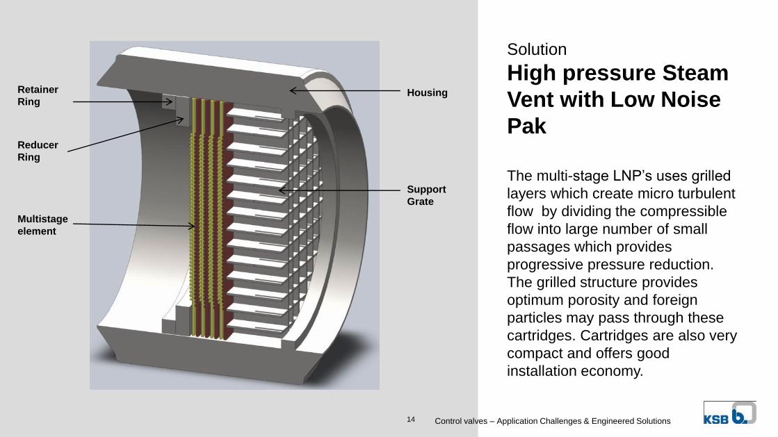
The multi-stage LNP’s uses grilled
layers which create micro turbulent
flow by dividing the compressible
flow into large number of small
passages which provides
progressive pressure reduction.
The grilled structure provides
optimum porosity and foreign
particles may pass through these
cartridges. Cartridges are also very
compact and offers good
installation economy.
Solution
High pressure Steam
Vent with Low Noise
Pak
Housing
Support
Grate
Retainer
Ring
Reducer
Ring
Multistage
element
Control valves – Application Challenges & Engineered Solutions14
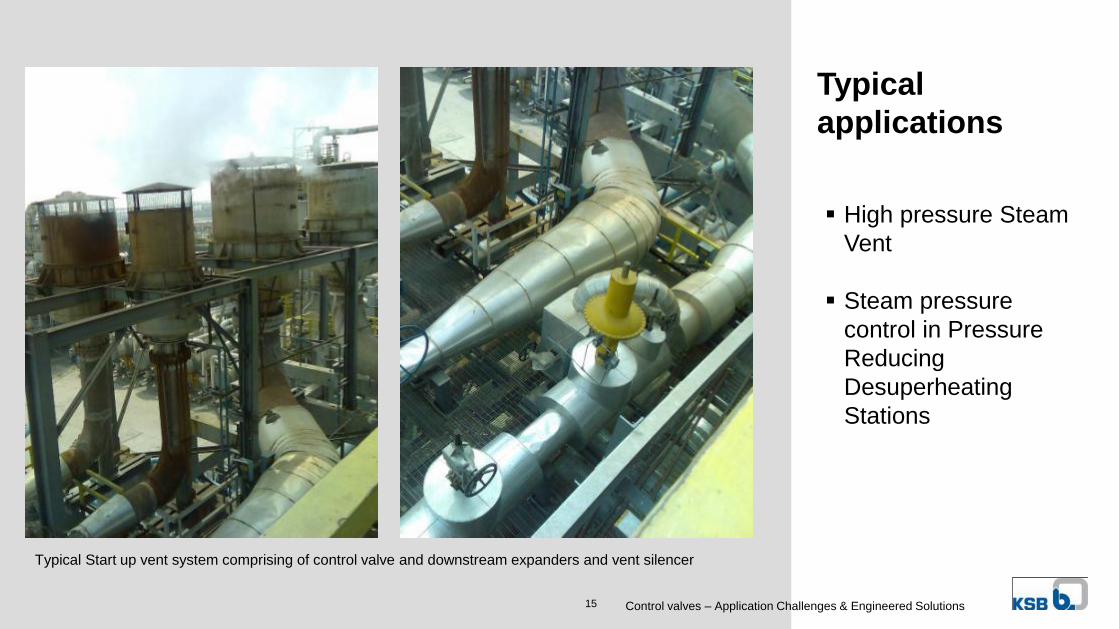
Typical
applications
Typical Start up vent system comprising of control valve and downstream expanders and vent silencer
High pressure Steam
Vent
Steam pressure
control in Pressure
Reducing
Desuperheating
Stations
Control valves – Application Challenges & Engineered Solutions15
© C
op
yri
gh
t K
SB
Aktie
ng
ese
llsch
aft
20
14
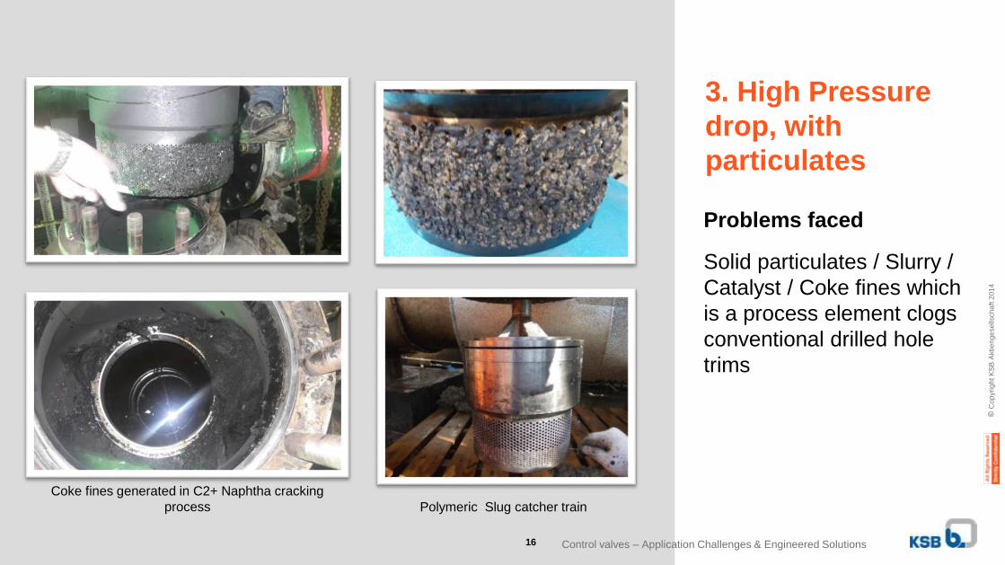
Problems faced
Solid particulates / Slurry /
Catalyst / Coke fines which
is a process element clogs
conventional drilled hole
trims
Polymeric Slug catcher train
Coke fines generated in C2+ Naphtha cracking
process
3. High Pressure
drop, with
particulates
Control valves – Application Challenges & Engineered Solutions16
© C
op
yri
gh
t K
SB
Aktie
ng
ese
llsch
aft
20
14
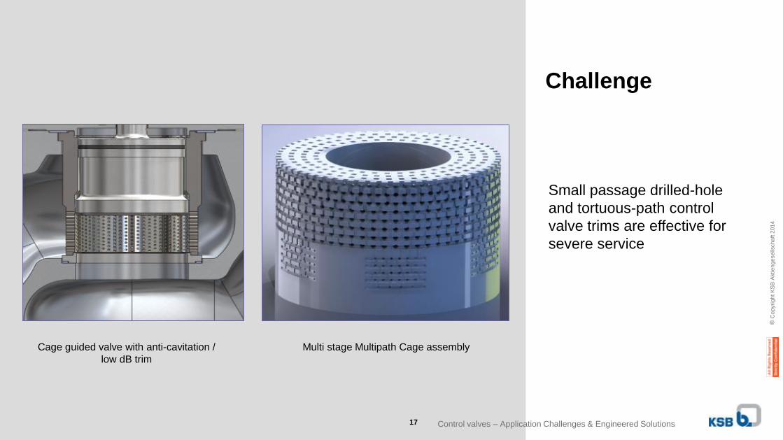
Small passage drilled-hole
and tortuous-path control
valve trims are effective for
severe service
Challenge
Cage guided valve with anti-cavitation /
low dB trim
Multi stage Multipath Cage assembly
Control valves – Application Challenges & Engineered Solutions17
© C
op
yri
gh
t K
SB
Aktie
ng
ese
llsch
aft
20
14
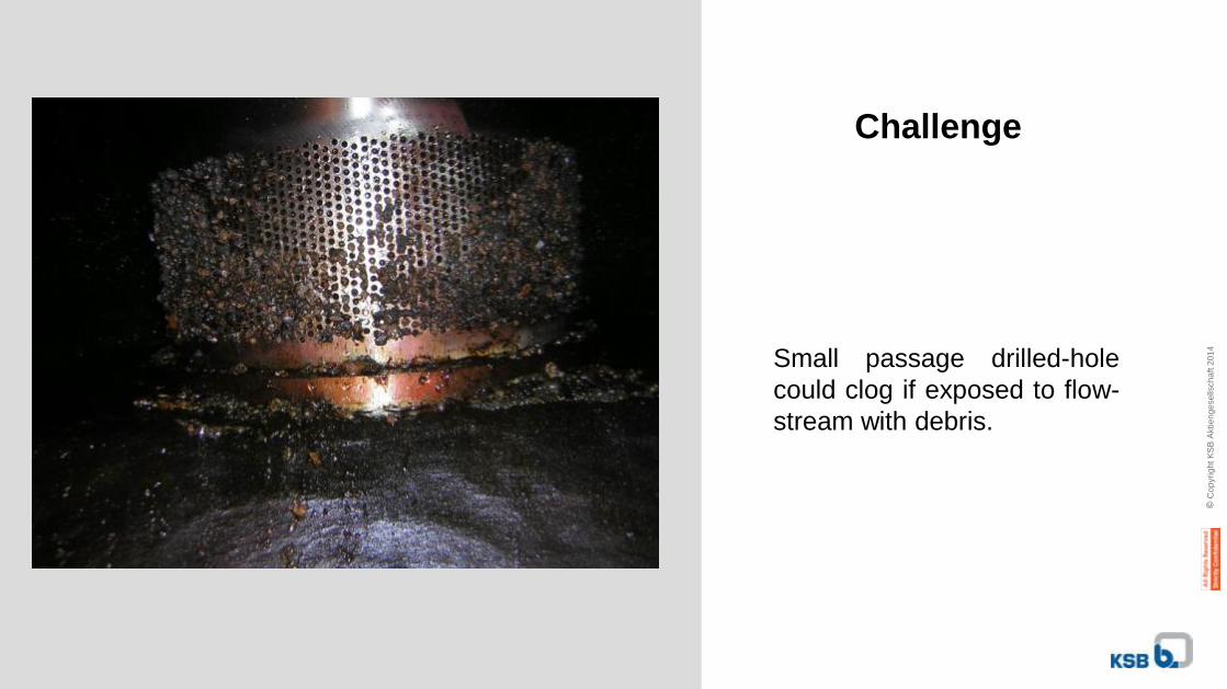
Small passage drilled-hole
could clog if exposed to flow-
stream with debris.
Challenge
© C
op
yri
gh
t K
SB
Aktie
ng
ese
llsch
aft
20
14
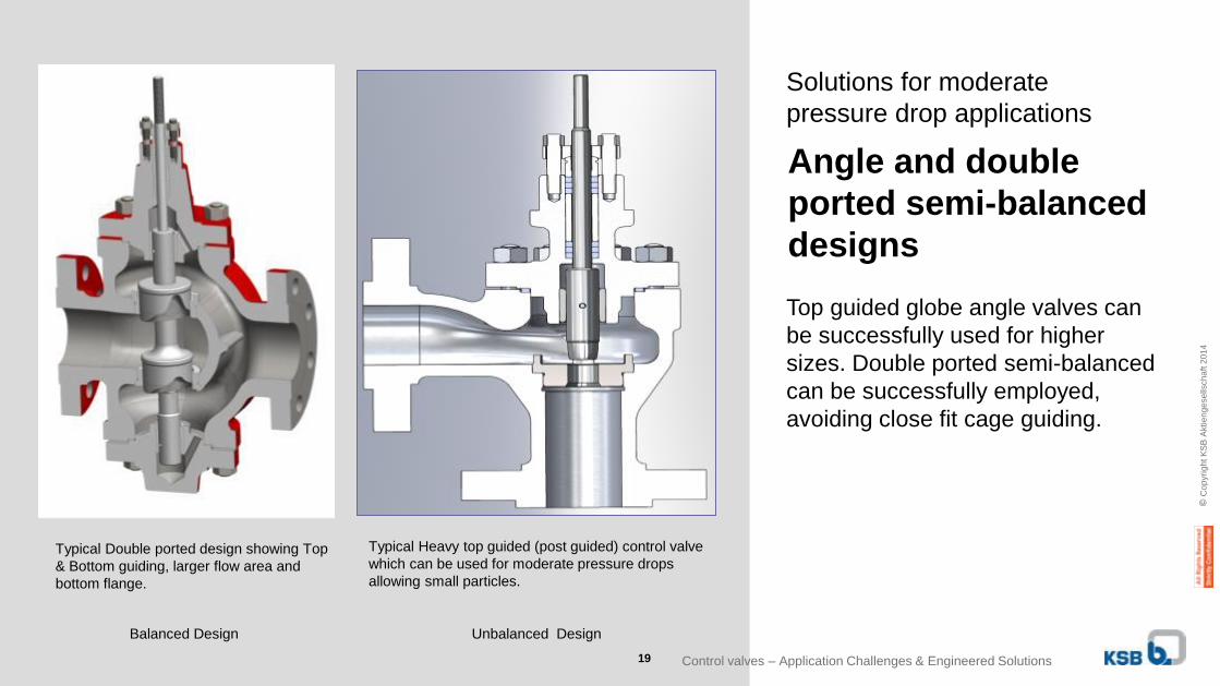
Typical Double ported design showing Top
& Bottom guiding, larger flow area and
bottom flange.
Typical Heavy top guided (post guided) control valve
which can be used for moderate pressure drops
allowing small particles.
Solutions for moderate
pressure drop applications
Angle and double
ported semi-balanced
designs
Top guided globe angle valves can
be successfully used for higher
sizes. Double ported semi-balanced
can be successfully employed,
avoiding close fit cage guiding.
Balanced Design Unbalanced Design
Control valves – Application Challenges & Engineered Solutions19
© C
op
yri
gh
t K
SB
Aktie
ng
ese
llsch
aft
20
14
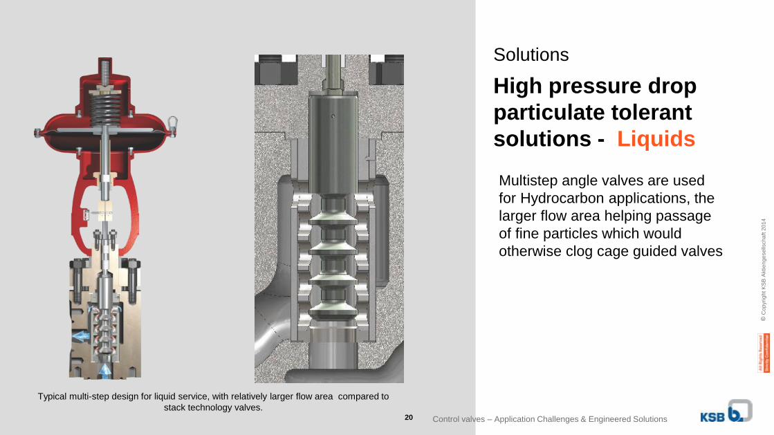
Typical multi-step design for liquid service, with relatively larger flow area compared to
stack technology valves.
Solutions
High pressure drop
particulate tolerant
solutions - Liquids
Multistep angle valves are used
for Hydrocarbon applications, the
larger flow area helping passage
of fine particles which would
otherwise clog cage guided valves
Control valves – Application Challenges & Engineered Solutions20
© C
op
yri
gh
t K
SB
Aktie
ng
ese
llsch
aft
20
14
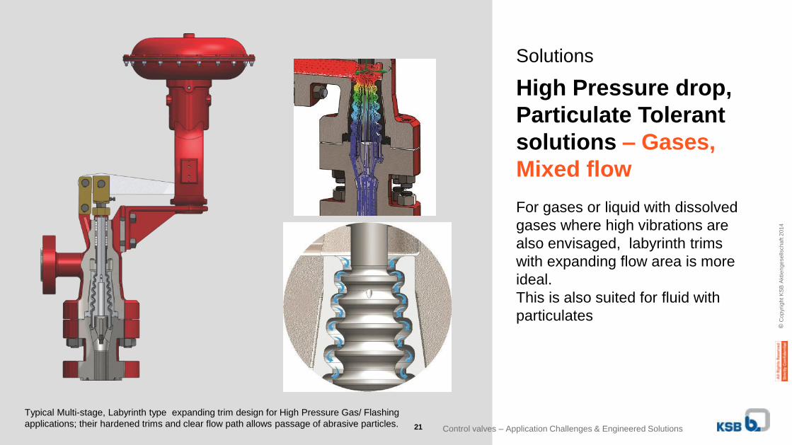
Typical Multi-stage, Labyrinth type expanding trim design for High Pressure Gas/ Flashing
applications; their hardened trims and clear flow path allows passage of abrasive particles.
Solutions
High Pressure drop,
Particulate Tolerant
solutions – Gases,
Mixed flow
For gases or liquid with dissolved
gases where high vibrations are
also envisaged, labyrinth trims
with expanding flow area is more
ideal.
This is also suited for fluid with
particulates
Control valves – Application Challenges & Engineered Solutions21
© C
op
yri
gh
t K
SB
Aktie
ng
ese
llsch
aft
20
14
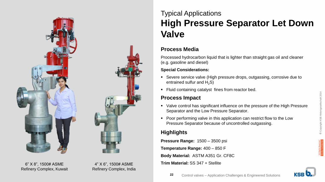
Typical Applications
High Pressure Separator Let Down
Valve
4” X 6”, 1500# ASME
Refinery Complex, India
Highlights
6” X 8”, 1500# ASME
Refinery Complex, Kuwait
Pressure Range: 1500 – 3500 psi
Temperature Range: 400 – 850 F
Body Material: ASTM A351 Gr. CF8C
Trim Material: SS 347 + Stellite
Process Media
Processed hydrocarbon liquid that is lighter than straight gas oil and cleaner
(e.g. gasoline and diesel)
Special Considerations:
Severe service valve (High pressure drops, outgassing, corrosive due to
entrained sulfur and H2S)
Fluid containing catalyst fines from reactor bed.
Process Impact
Valve control has significant influence on the pressure of the High Pressure
Separator and the Low Pressure Separator.
Poor performing valve in this application can restrict flow to the Low
Pressure Separator because of uncontrolled outgassing.
Control valves – Application Challenges & Engineered Solutions22
© C
op
yri
gh
t K
SB
Aktie
ng
ese
llsch
aft
20
14
23
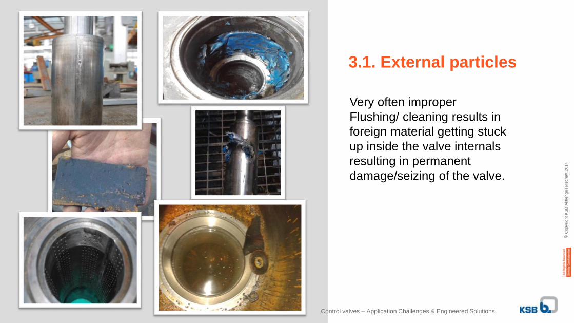
3.1. External particles
Very often improper
Flushing/ cleaning results in
foreign material getting stuck
up inside the valve internals
resulting in permanent
damage/seizing of the valve.
Control valves – Application Challenges & Engineered Solutions
© C
op
yri
gh
t K
SB
Aktie
ng
ese
llsch
aft
20
14
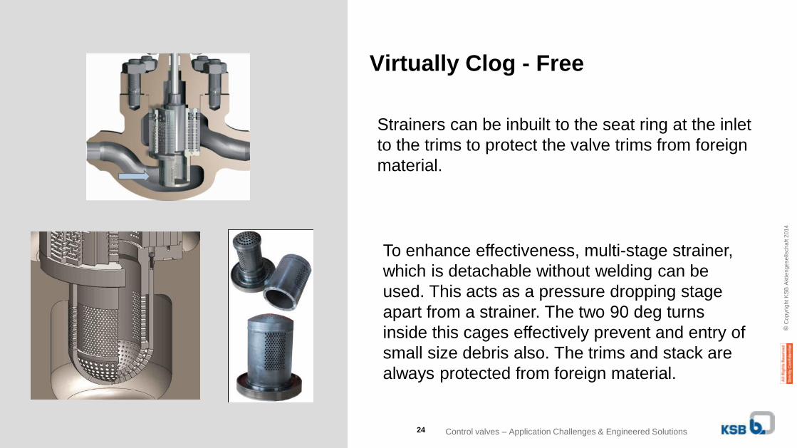
Virtually Clog - Free
To enhance effectiveness, multi-stage strainer,
which is detachable without welding can be
used. This acts as a pressure dropping stage
apart from a strainer. The two 90 deg turns
inside this cages effectively prevent and entry of
small size debris also. The trims and stack are
always protected from foreign material.
Strainers can be inbuilt to the seat ring at the inlet
to the trims to protect the valve trims from foreign
material.
Control valves – Application Challenges & Engineered Solutions24
© C
op
yri
gh
t K
SB
Aktie
ng
ese
llsch
aft
20
14
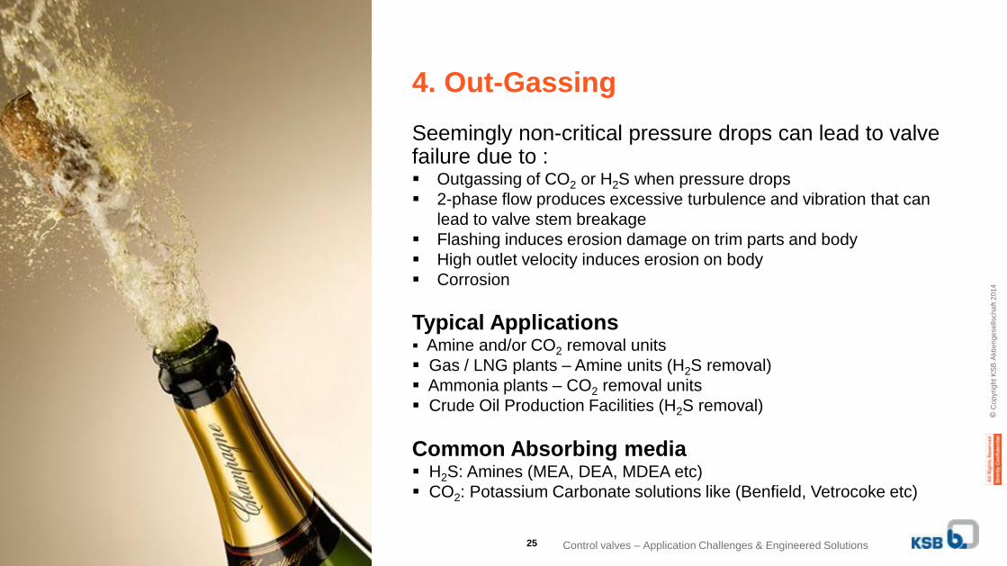
Seemingly non-critical pressure drops can lead to valve failure due to : Outgassing of CO2 or H2S when pressure drops
2-phase flow produces excessive turbulence and vibration that can
lead to valve stem breakage
Flashing induces erosion damage on trim parts and body
High outlet velocity induces erosion on body
Corrosion
Typical Applications Amine and/or CO2 removal units
Gas / LNG plants – Amine units (H2S removal)
Ammonia plants – CO2 removal units
Crude Oil Production Facilities (H2S removal)
Common Absorbing media H2S: Amines (MEA, DEA, MDEA etc)
CO2: Potassium Carbonate solutions like (Benfield, Vetrocoke etc)
4. Out-Gassing
Control valves – Application Challenges & Engineered Solutions25
© C
op
yri
gh
t K
SB
Aktie
ng
ese
llsch
aft
20
14
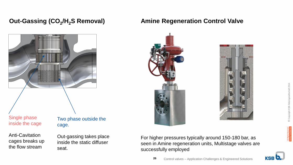
Single phase
inside the cage
Anti-Cavitation
cages breaks up
the flow stream
Two phase outside the
cage.
Out-gassing takes place
inside the static diffuser
seat.
Out-Gassing (CO2/H2S Removal) Amine Regeneration Control Valve
For higher pressures typically around 150-180 bar, as
seen in Amine regeneration units, Multistage valves are
successfully employed
Control valves – Application Challenges & Engineered Solutions26
© C
op
yri
gh
t K
SB
Aktie
ng
ese
llsch
aft
20
14
• Often forgotten aspect during design phase is the gland leak potential, which gains utmost relevance
• Apart from emission to ecology, the leakage also can lead to loss of energy, product or health hazard
• Control of emission and minor leakage is a major challenge in process industries
• Different type of packing and Seals are used to isolate the fluid
• Clean Air Act enforced to control air pollution – EPA, USA
• Emissions limited below 500ppmv in stringent cases to 100ppmv
27
Fugitive Emission & Mitigation in Control Valves
© C
op
yri
gh
t K
SB
Aktie
ng
ese
llsch
aft
20
14
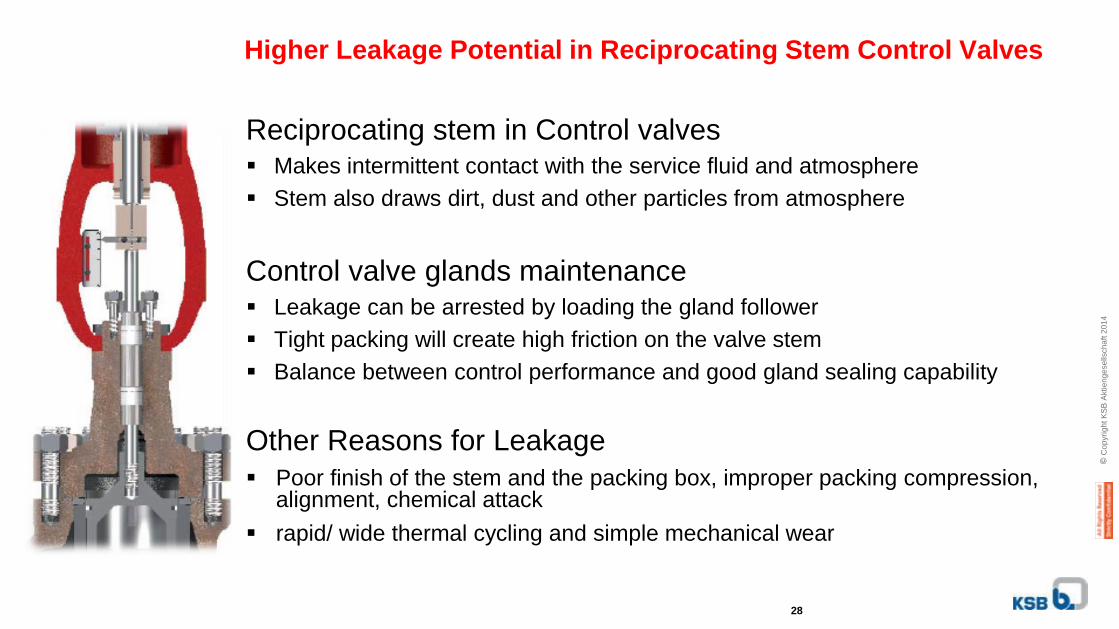
Higher Leakage Potential in Reciprocating Stem Control Valves
Reciprocating stem in Control valves Makes intermittent contact with the service fluid and atmosphere
Stem also draws dirt, dust and other particles from atmosphere
Control valve glands maintenance Leakage can be arrested by loading the gland follower
Tight packing will create high friction on the valve stem
Balance between control performance and good gland sealing capability
Other Reasons for Leakage
Poor finish of the stem and the packing box, improper packing compression, alignment, chemical attack
rapid/ wide thermal cycling and simple mechanical wear
28
© C
op
yri
gh
t K
SB
Aktie
ng
ese
llsch
aft
20
14
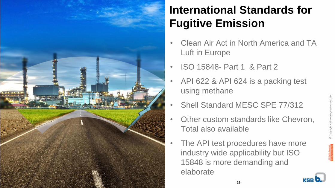
International Standards for
Fugitive Emission
• Clean Air Act in North America and TA
Luft in Europe
• ISO 15848- Part 1 & Part 2
• API 622 & API 624 is a packing test
using methane
• Shell Standard MESC SPE 77/312
• Other custom standards like Chevron,
Total also available
• The API test procedures have more
industry wide applicability but ISO
15848 is more demanding and
elaborate29
61st Annual ISA POWID Symposium, 26-28 June 2018, Knoxville, TNCopyright 2018. ISA All rights reserved. www.isa.org
No part of this work may be reproduced, stored in a retrieval system, or transmitted in any form or by means, electronic, mechanical, photocopying, recording or otherwise, without the prior
written permission of the publisher.
30
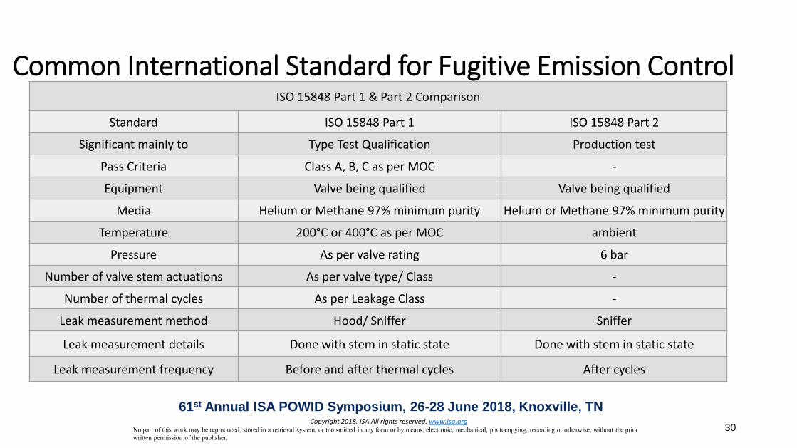
ISO 15848 Part 1 & Part 2 Comparison
Standard ISO 15848 Part 1 ISO 15848 Part 2
Significant mainly to Type Test Qualification Production test
Pass Criteria Class A, B, C as per MOC -
Equipment Valve being qualified Valve being qualified
Media Helium or Methane 97% minimum purity Helium or Methane 97% minimum purity
Temperature 200°C or 400°C as per MOC ambient
Pressure As per valve rating 6 bar
Number of valve stem actuations As per valve type/ Class -
Number of thermal cycles As per Leakage Class -
Leak measurement method Hood/ Sniffer Sniffer
Leak measurement details Done with stem in static state Done with stem in static state
Leak measurement frequency Before and after thermal cycles After cycles
Common International Standard for Fugitive Emission Control
61st Annual ISA POWID Symposium, 26-28 June 2018, Knoxville, TNCopyright 2018. ISA All rights reserved. www.isa.org
No part of this work may be reproduced, stored in a retrieval system, or transmitted in any form or by means, electronic, mechanical, photocopying, recording or otherwise, without the prior
written permission of the publisher.
ISA-D: "Petroleum & Power Automation Meet-2018" (PPAM-2018)31
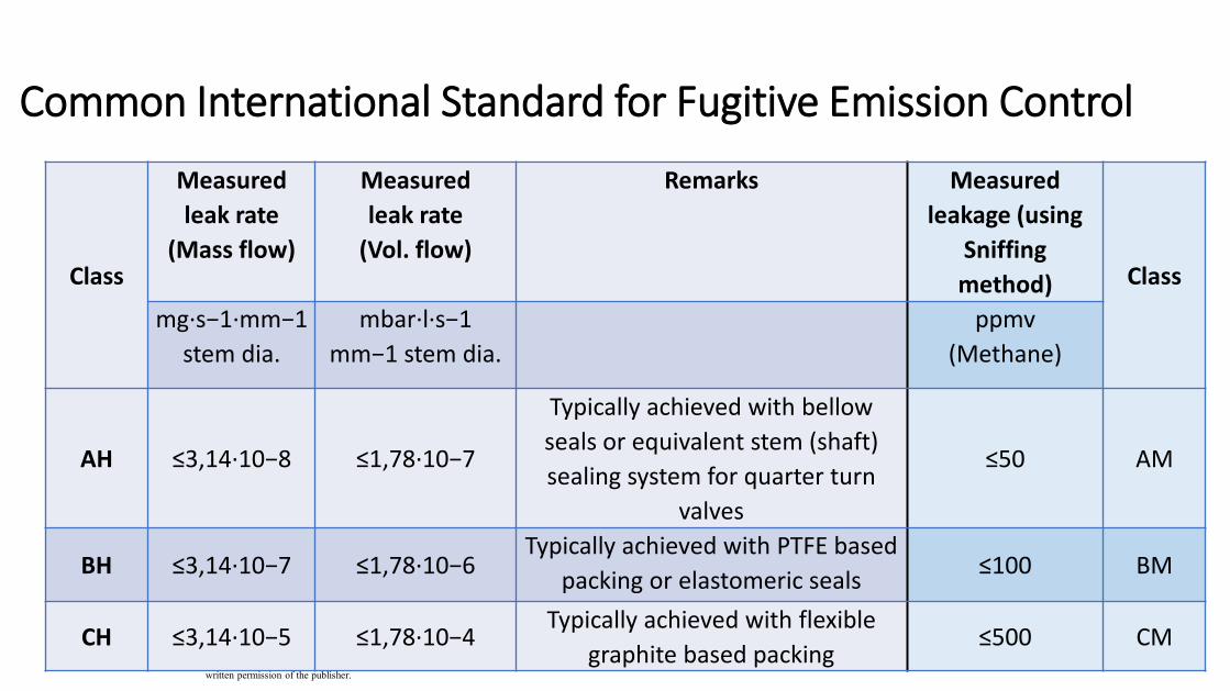
Class
Measured
leak rate
(Mass flow)
Measured
leak rate
(Vol. flow)
Remarks Measured
leakage (using
Sniffing
method) Class
mg·s−1·mm−1
stem dia.
mbar·l·s−1
mm−1 stem dia.
ppmv
(Methane)
AH ≤3,14·10−8 ≤1,78·10−7
Typically achieved with bellow
seals or equivalent stem (shaft)
sealing system for quarter turn
valves
≤50 AM
BH ≤3,14·10−7 ≤1,78·10−6Typically achieved with PTFE based
packing or elastomeric seals≤100 BM
CH ≤3,14·10−5 ≤1,78·10−4Typically achieved with flexible
graphite based packing≤500 CM
Common International Standard for Fugitive Emission Control
© C
op
yri
gh
t K
SB
Aktie
ng
ese
llsch
aft
20
14
ISA-D: "Petroleum & Power Automation Meet-2018" (PPAM-2018)
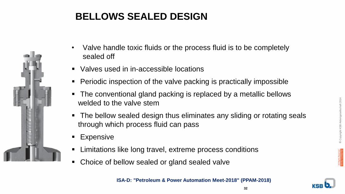
BELLOWS SEALED DESIGN
• Valve handle toxic fluids or the process fluid is to be completely
sealed off
Valves used in in-accessible locations
Periodic inspection of the valve packing is practically impossible
The conventional gland packing is replaced by a metallic bellows
welded to the valve stem
The bellow sealed design thus eliminates any sliding or rotating seals
through which process fluid can pass
Expensive
Limitations like long travel, extreme process conditions
Choice of bellow sealed or gland sealed valve
32
© C
op
yri
gh
t K
SB
Aktie
ng
ese
llsch
aft
20
14
ISA-D: "Petroleum & Power Automation Meet-2018" (PPAM-2018)
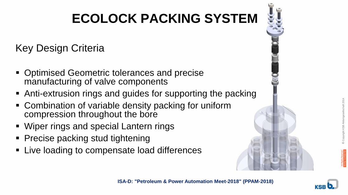
ECOLOCK PACKING SYSTEM
Key Design Criteria
Optimised Geometric tolerances and precise manufacturing of valve components
Anti-extrusion rings and guides for supporting the packing
Combination of variable density packing for uniform compression throughout the bore
Wiper rings and special Lantern rings
Precise packing stud tightening
Live loading to compensate load differences
© C
op
yri
gh
t K
SB
Aktie
ng
ese
llsch
aft
20
14
Control valves – Application Challenges & Engineered Solutions
Thank You