Vait trac-wat
5
GAS & WATER SOLUTIONS
-
Upload
omb-saleri -
Category
Documents
-
view
279 -
download
0
Transcript of Vait trac-wat
GAS & WATER SOLUTIONS
OMB Saleri S.p.A / FARO Srl | Via Rose di Sotto, 38/C 25126 Brescia (BS) Italy | tel. +39 030 31 95 801 | fax. 030 37 32 872 | www.omb-saleri.it | [email protected]
VAIT
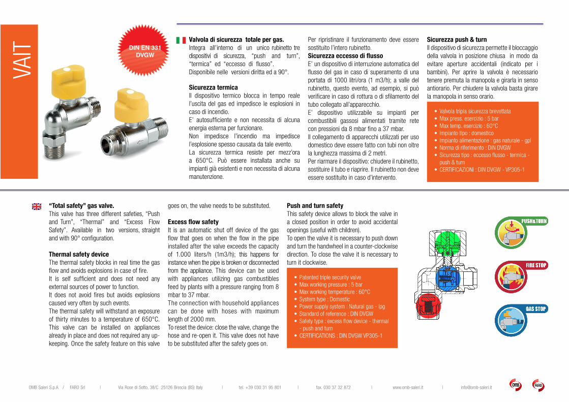
Valvola di sicurezza totale per gas.Integra all’interno di un unico rubinetto tre dispositivi di sicurezza, “push and turn”, “termica” ed “eccesso di flusso”. Disponibile nelle versioni diritta ed a 90°.
Sicurezza termicaIl dispositivo termico blocca in tempo reale l’uscita del gas ed impedisce le esplosioni in caso di incendio.E’ autosufficiente e non necessita di alcuna energia esterna per funzionare.Non impedisce l’incendio ma impedisce l’esplosione spesso causata da tale evento.La sicurezza termica resiste per mezz’ora a 650°C. Può essere installata anche su impianti già esistenti e non necessita di alcuna manutenzione.
Per ripristinare il funzionamento deve essere sostituito l’intero rubinetto.
Sicurezza eccesso di flussoE’ un dispositivo di interruzione automatica del flusso del gas in caso di superamento di una portata di 1000 litri/ora (1 m3/h); a valle del rubinetto, questo evento, ad esempio, si può verificare in caso di rottura o di sfilamento del tubo collegato all’apparecchio.E’ dispositivo utilizzabile su impianti per combustibili gassosi alimentati tramite rete con pressioni da 8 mbar fino a 37 mbar.Il collegamento di apparecchi utilizzati per uso domestico deve essere fatto con tubi non oltre la lunghezza massima di 2 metri.Per riarmare il dispositivo: chiudere il rubinetto, sostituire il tubo e riaprire. Il rubinetto non deve essere sostituito in caso d’intervento.
Sicurezza push & turnIl dispositivo di sicurezza permette il bloccaggio della valvola in posizione chiusa in modo da evitare aperture accidentali (indicato per i bambini). Per aprire la valvola è necessario tenere premuta la manopola e girarla in senso antiorario. Per chiudere la valvola basta girare la manopola in senso orario.
“Total safety” gas valve. This valve has three different safeties, “Push and Turn”, “Thermal” and “Excess Flow Safety”. Available in two versions, straight and with 90° configuration.
Thermal safety deviceThe thermal safety blocks in real time the gas flow and avoids explosions in case of fire.It is self sufficient and does not need any external sources of power to function.It does not avoid fires but avoids explosions caused very often by such events.The thermal safety will withstand an exposure of thirty minutes to a temperature of 650°C.This valve can be installed on appliances already in place and does not required any up-keeping. Once the safety feature on this valve
goes on, the valve needs to be substituted.
Excess flow safetyIt is an automatic shut off device of the gas flow that goes on when the flow in the pipe installed after the valve exceeds the capacity of 1.000 liters/h (1m3/h); this happens for instance when the pipe is broken or disconnected from the appliance. This device can be used with appliances utilizing gas combustibles feed by plants with a pressure ranging from 8 mbar to 37 mbar.The connection with household appliances can be done with hoses with maximum length of 2000 mm. To reset the device: close the valve, change the hose and re-open it. This valve does not have to be substituted after the safety goes on.
Push and turn safetyThis safety device allows to block the valve in a closed position in order to avoid accidental openings (useful with children).To open the valve it is necessary to push down and turn the handwheel in a counter-clockwise direction. To close the valve it is necessary to turn it clockwise.
•Patented triple security valve •Max working pressure : 5 bar•Max working temperature : 60°C•System type : Domestic•Power supply system : Natural gas - lpg•Standard of reference : DIN DVGW•Safety type : excess flow device - thermal
- push and turn•CERTIFICATIONS : DIN DVGW VP305-1
• Valvola tripla sicurezza brevettata •Max press. esercizio : 5 bar•Max temp. esercizio : 60°C• Impianto tipo : domestico• Impianto alimentazione : gas naturale - gpl•Norma di riferimento : DIN DVGW•Sicurezza tipo : eccesso flusso - termica -
push & turn•CERTIFICAZIONI : DIN DVGW - VP305-1
DIN EN 331DVGW
OMB Saleri S.p.A / FARO Srl | Via Rose di Sotto, 38/C 25126 Brescia (BS) Italy | tel. +39 030 31 95 801 | fax. 030 37 32 872 | www.omb-saleri.it | [email protected]
TRAC
PIPE
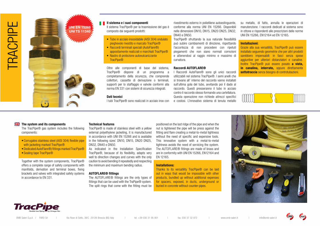
Il sistema e i suoi componentiIl sistema TracPipe® per la trasmissione del gas è composto dai seguenti prodotti:
• Tubo in acciaio inossidabile (AISI 304) ondulato pieghevole rivestito e marcato TracPipe®
• Raccordi terminali speciali (AutoFlare®) appositamente realizzati e marchiati TracPipe®
• Nastro di protezione autovulcanizzante TracPipe®
Oltre alle componenti di base del sistema, TracPipe® dispone di un programma a completamento della sicurezza, che comprende collettori, cassette di derivazione o terminali, supporti per lo staffaggio e valvole conformi alla norma EN 331 con sistemi di sicurezza integrati.
Dati tecniciI tubi TracPipe® sono realizzati in acciaio inox con
rivestimento esterno in polietilene autoestinguente, conforme alla norma UNI EN 15266. Disponibili nelle dimensioni DN10, DN15, DN20 DN25, DN32, DN40 e DN50.TracPipe® sfruttando la sua naturale flessibilità può subire cambiamenti di direzione, rispettando l’accortezza di non procedere con ripetuti piegamenti che non siano normali correzioni e attenendosi al raggio minimo e massimo di curvatura.
Raccordi AUTOFLARE® I Raccordi AutoFlare® sono gli unici raccordi utilizzabili nel sistema TracPipe®. I semi anelli che si trovano all’ interno del raccordo vanno installati sull’ultima gola del tubo, avvitando poi il dado al raccordo. Questi presseranno il tubo in acciaio contro il raccordo stesso formando una cartellatura. Questa operazione non richiede attrezzi specifici e costosi. L’innovativo sistema di tenuta metallo
su metallo, di fatto, annulla le operazioni di manutenzione. I raccordi dedicati al sistema sono in ottone e rispondenti alle prescrizioni delle norme UNI EN 15266, EN12164 ed EN 12165.
Installazioni:Grazie alla sua versatilità, TracPipe® può essere installato seguendo geometrie che per altri prodotti sarebbero impensabili: in fasci senza spese aggiuntive per ulteriori distanziatori e canaline. Inoltre TracPipe® può essere posato a vista, in canalina, interrato, oppure direttamente sottotraccia senza bisogno di controtubazioni.
The system and its components The TracPipe® gas system includes the following components:
•Corrugates stainless steel (AISI 304) flexible pipe with jacketing marked TracPipe®
•Dedicated AutoFlare®) fittings marked TracPipe®•Sealing tape TracPipe®
Together with the system components, TracPipe® offers a complete range of safety components with manifolds, derivation and terminal boxes, fixing brackets and valves with integrated safety systems in accordance to EN 331.
Technical features TracPipe® is made of stainless steel with a yellow external polyethylene jacketing, it is manufactured in accordance with UNI EN 15266 and is available in the following sizes¨ DN10, DN15, DN20 DN25, DN32, DN40 e DN50.As indicated in the Installation Specification TracPipe®, because of its flexibility, adapts very well to direction changes and curves with the only caution to avoid bending it repeatedly and respecting the minimum and maximum bending radius.
AUTOFLARE® fittingsThe AUTOFLARE® fittings are the only types of fittings that can be used with the TraPipe® system. The split rings that come with the fitting must be
positioned on the last ridge of the pipe and when the nut is tightened the pipe will be press against the fitting and flare creating a metal-to-metal tightness without the need of specific and expensive tools. This innovative system with a metal-to-metal tightness avoids the need of servicing the system. The AUTOFLARE® fittings are made of brass and are in conformity with UNI EN 15266, EN12164 and EN 12165.
Installations:Thanks to its versatility TracPipe® can be laid out in ways that would be impossible with other products, bundled up without additional expenses for spacers, exposed, in ducts, underground or buried in concrete without counter-pipes.
UNI EN 15266UNI TS 11340
OMB Saleri S.p.A / FARO Srl | Via Rose di Sotto, 38/C 25126 Brescia (BS) Italy | tel. +39 030 31 95 801 | fax. 030 37 32 872 | www.omb-saleri.it | [email protected]
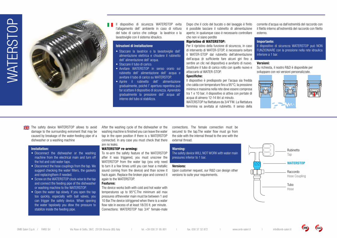
Il dispositivo di sicurezza WATERSTOP evita l’allagamento dell’ ambiente in caso di rottura del tubo di carico che collega la lavatrice o la lavastoviglie con il sistema idraulico.
Istruzioni di installazione
• Staccare la lavatrice o la lavastoviglie dall’ alimentazione elettrica e chiudere il rubinetto dell’ alimentazione dell’ acqua.
• Staccare il tubo di carico. • Avvitare WATERSTOP in senso orario sul
rubinetto dell’ alimentazione dell’ acqua e avvitare il tubo di carico su WATERSTOP.
• Aprire il rubinetto dell’ alimentazione gradualmente, poiché l’ apertura repentina può far scattare il dispositivo di sicurezza. Aprendolo gradualmente la pressione dell’ acqua all’ interno del tubo si stabilizza.
Dopo che il ciclo del bucato o del lavaggio è finito è possibile lasciare il rubinetto di alimentazione aperto; in qualunque caso è necessario controllare che non vi siano perditeRipristino di WATERSTOP:Per il ripristino della funzione di sicurezza, in caso di intervento di WATER-STOP, è necessario svitare il WATER-STOP dal rubinetto dell’alimentazione dell’acqua (è sufficiente fare alcuni giri fino a sentire un clic nel dispositivo) e avvitarlo di nuovo. Sostituire il tubo di carico rotto con quello nuovo e attaccarlo al WATER-STOP.Specifiche:Il dispositivo è predisposto per l’acqua sia fredda che calda con temperature fino a 95°C; la pressione minima e massima nella rete deve essere compresa tra 1 e 10 bar; il dispositivo si attiva con portate di acqua di almeno 12-14 litri al minuto.WATERSTOP ha filettature da 3/4”FM. La filettatura femmina va avvitata al rubinetto. Il senso della
corrente d’acqua va dall’estremità del raccordo con il filetto interno all’estremità del raccordo con filetto esterno.
Importante:Il dispositivo di sicurezza WATERSTOP può NON FUNZIONIARE con la pressione nella rete idraulica inferiore a 1 bar.
Versioni:Su richiesta, il nostro R&D è disponibile persviluppare con voi versioni personalizzate.
The safety device WATERSTOP allows to avoid damage to the surrounding eviroment that may be caused by breakage of the water-feeding pipe of a dishwasher or a washing machine
Installation: • Disconnect the dishwasher or the washing
machine from the electrical main and turn off the hot and cold water taps.
• Disconnect the hose couplings from the tap. We suggest checking the water filters, the gaskets and replacingthem if needed.
• Screw on the WATERSTOP clock-wise to the tap and connect the feeding pipe of the dishwasher or washing machine to the WATERSTOP.
• Open the water tap slowly. If you open the tap too quickly, especially with ball valves, you can trigger the safety device. When opening the water tapslowly you dlow the pressure to stabilize inside the feeding pipe.
After the washing cycle of the dishwasher or the washing machine is finished you can leave the water tap in the open position if there is s WATERSTOP connected. In any case you must check that there are no leaks.WATERSTOP re-arming:To re-arm the safety feature of the WATERSTOP after it was triggered, you must unscrew the WATERSTOP from the water tap (you only need to turn it a few times until you can hear a metallic sound coming from the device) and than screw it hack again. Replace the broken pipe and connect it again to the WATERSTOP.Features:The device works both with cold and hot water with temperatures up to 95°C.The minimum aid max pressures ofthevveter main must be between 1 and 10 Bar.The device istriggered when there is a water flow rate in excess of at least 18/20 lt. per minute.Connections: WATERSTOP has 3/4” female-male
connections. The female connection must be secured to the tap.The water flow must go from the side with the internal thread to the one with the external thread.
Warning:The safety device WILL NOT WORK with water main pressures inferior to 1 bar.
Versions:Upon customer request, our R&D can design other versions to suite your requirements.
WAT
ERST
OP
RubinettoTap
WATERSTOP
RaccordoHose Coupling
TuboHose
OMB Saleri SpA Via Rose di Sotto, 38/C25126 Brescia (BS) Italy t e l .+39.030.31.95 .801 fax .+39.030.37.32.872 w w w . o m b - s a l e r i . i t i n f o @ o m b - s a l e r i . i t