V230 VALVE OPERATING MANUAL - Hawako Siata V230.pdf · S.I.A.T.A. srl Società Italiana...
27
S.I.A.T.A. srl Società Italiana apparecchiature trattamento acqua MAN0021 Rev. B Pag 1 di 27 V230 VALVE OPERATING MANUAL
Transcript of V230 VALVE OPERATING MANUAL - Hawako Siata V230.pdf · S.I.A.T.A. srl Società Italiana...
S.I.A.T.A. srl Società Italiana apparecchiature trattamento acqua MAN0021 Rev. B Pag 1 di 27
V230 VALVEOPERATING MANUAL
S.I.A.T.A. srl Società Italiana apparecchiature trattamento acqua MAN0021 Rev. B Pag 2 di 27
DOCUMENT REVISION REVISION NOTES DATEMAN0029 A BOZZA 19/06/98MAN0029 B EMISSIONE
S.I.A.T.A. srl Società Italiana apparecchiature trattamento acqua MAN0021 Rev. B Pag 3 di 27
Index¾ General Features – Technical Specification 4¾ Dimension 5¾ Softening Function Schemes 6¾ Softening Version Schemes 7¾ Demineralisation Version Schemes 9¾ Variations of Use = Controller/Pilot Valves Connections 10¾ Injectors & Flow Controls 13¾ Components of Standard Base Valve 14¾ Standard Volume Version 15¾ Standard Filtration Version 16¾ Duplex and Demineralisation Valve Version 17¾ Table for Controllers Selection 18¾ Automatic Remote By-pass for Softners & for Filter 19¾ Automatic Remote By-pass Components 20¾ Automatic By-pass Function 21¾ Chlorine producer Components 22¾ Tips and Suggestions 23¾ Spare Parts Kit 24¾ Accessories and Spare Parts 25¾ Intervention of ordinary maintenance 26

S.I.A.T.A. srl Società Italiana apparecchiature trattamento acqua MAN0021 Rev. B Pag 4 di 27
GENERAL FEATURES
"V230" valves are the essential elements in building the following systems:a) simplex, duplex or multi-tank softening (decalcification) systems for domestic, laboratory and
industrial use;b) simplex or duplex demineralisation and dealkalisation systems for laboratory and industrial use
and all other uses requiring water with characteristics of guaranteed quality;c) simplex or duplex filtering systems for all of the previous applications.The valves are made with materials that guarantee utmost resistance and quality. They areavailable with a vast range of controllers for every operation phase of service and regeneration,starting from the simplest electronic basic controller with weekly clock to the sophisticatedelectronic controllers in various models which enable volume, volume-time control and salinitycontrol in MicroSiemens/cm, etc.In the electronic systems, all the intervention times of operation phases can be programmed inrelation to system type and dimension.For specific controller features, see the relative manual.
TECHNICAL SPECIFICATIONSOperating pressure From 1.5 to 6 bar
Maximum water flow with load loss of 1bar 44.09 US gpm. 25.7 UK gpmSee Table 1 for value variables -
Backwash water flow max. 17.64 US gpm 11Slow rinse water flow 0.44 to 2.65 US gpm 0.16
Fast rinse water flow (down-flow) max. 24.25 US gpmStatic resistance to pressure 22 bar
Maximum quantity of regenerative resin 200 l.Operating temperature From 5 to 40°C
Materials of main components ABS+FVTank connection ∅ 4”
Input output attachments 2” gas malePRESSURE DROP
For cod. 494-* see page 24

S.I.A.T.A. srl Società Italiana apparecchiature trattamento acqua MAN0021 Rev. B Pag 5 di 27
S.I.A.T.A. srl Società Italiana apparecchiature trattamento acqua MAN0021 Rev. B Pag 6 di 27
S.I.A.T.A. srl Società Italiana apparecchiature trattamento acqua MAN0021 Rev. B Pag 7 di 27
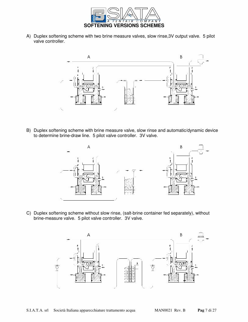
SOFTENING VERSIONS SCHEMES
A) Duplex softening scheme with two brine measure valves, slow rinse,3V output valve. 5 pilotvalve controller.
B) Duplex softening scheme with brine measure valve, slow rinse and automatic/dynamic deviceto determine brine-draw line. 5 pilot valve controller. 3V valve.
C) Duplex softening scheme without slow rinse, (salt-brine container fed separately), withoutbrine-measure valve. 5 pilot valve controller. 3V valve.
S.I.A.T.A. srl Società Italiana apparecchiature trattamento acqua MAN0021 Rev. B Pag 8 di 27
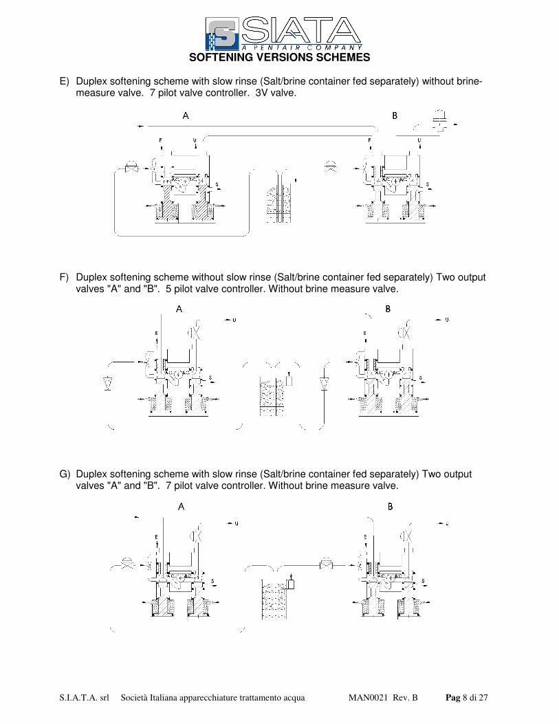
SOFTENING VERSIONS SCHEMES
E) Duplex softening scheme with slow rinse (Salt/brine container fed separately) without brine-measure valve. 7 pilot valve controller. 3V valve.
F) Duplex softening scheme without slow rinse (Salt/brine container fed separately) Two outputvalves "A" and "B". 5 pilot valve controller. Without brine measure valve.
G) Duplex softening scheme with slow rinse (Salt/brine container fed separately) Two outputvalves "A" and "B". 7 pilot valve controller. Without brine measure valve.
S.I.A.T.A. srl Società Italiana apparecchiature trattamento acqua MAN0021 Rev. B Pag 9 di 27
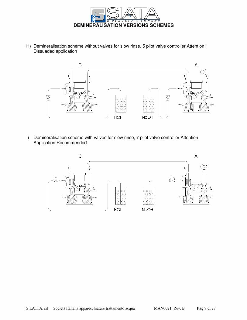
DEMINERALISATION VERSIONS SCHEMES
H) Demineralisation scheme without valves for slow rinse, 5 pilot valve controller.Attention!Dissuaded application
I) Demineralisation scheme with valves for slow rinse, 7 pilot valve controller.Attention!Application Recommended

S.I.A.T.A. srl Società Italiana apparecchiature trattamento acqua MAN0021 Rev. B Pag 10 di 27
VARIATION OF USE
Duplex softening connections referring to schemes “A”, “B”, “C” page 7.
Duplex softening connections referring to schemes “F” page 8.
S.I.A.T.A. srl Società Italiana apparecchiature trattamento acqua MAN0021 Rev. B Pag 11 di 27
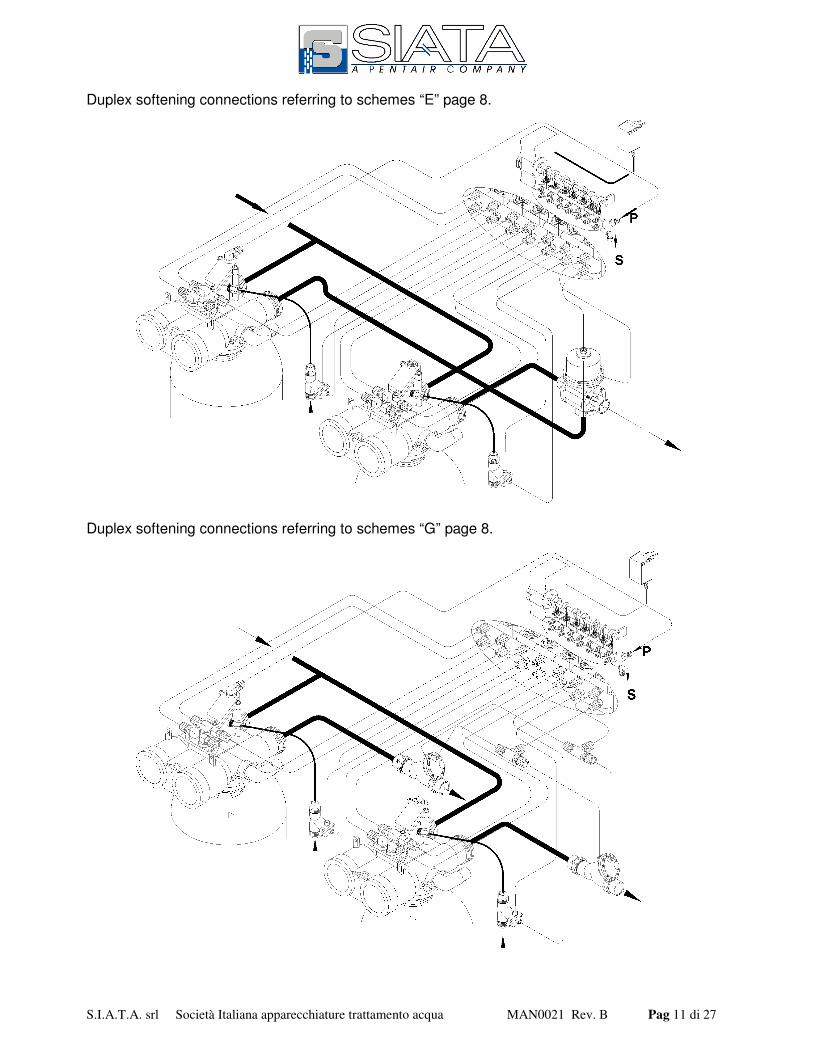
Duplex softening connections referring to schemes “E” page 8.
Duplex softening connections referring to schemes “G” page 8.
S.I.A.T.A. srl Società Italiana apparecchiature trattamento acqua MAN0021 Rev. B Pag 12 di 27
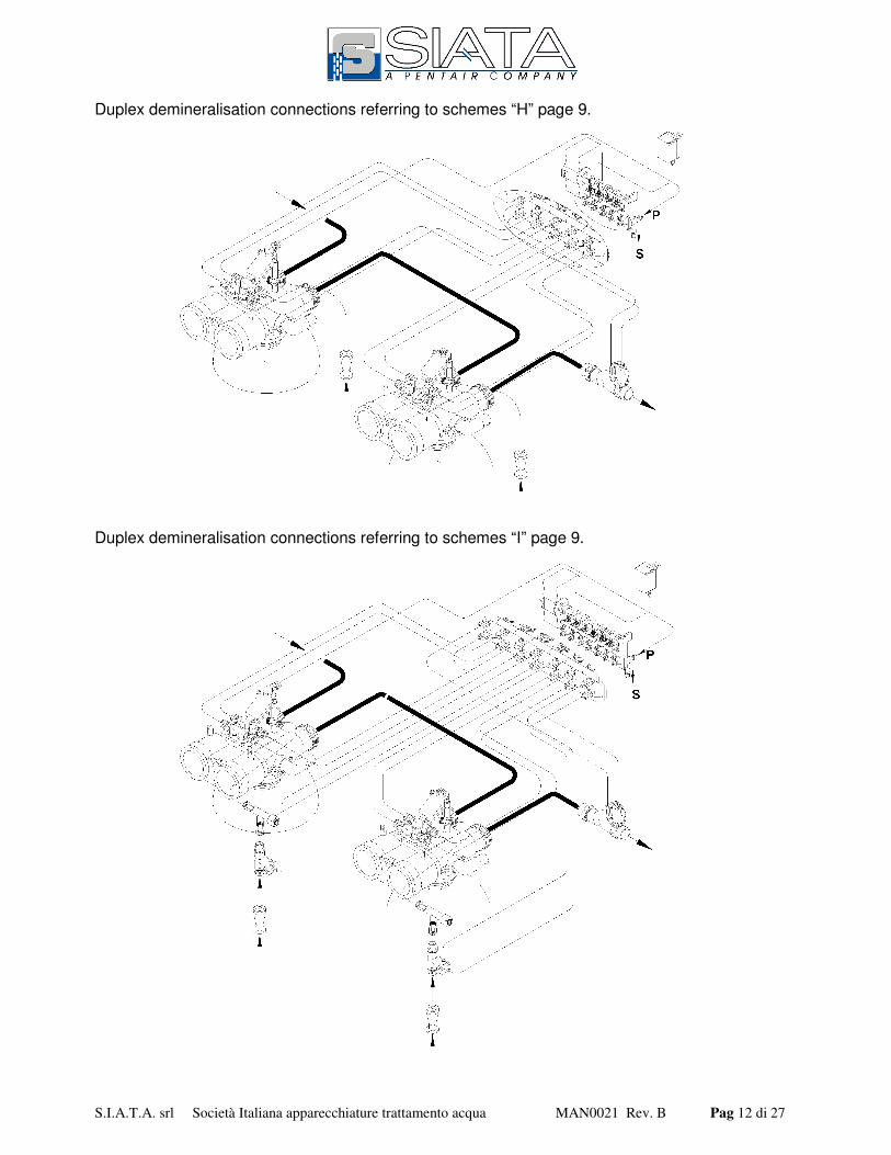
Duplex demineralisation connections referring to schemes “H” page 9.
Duplex demineralisation connections referring to schemes “I” page 9.

S.I.A.T.A. srl Società Italiana apparecchiature trattamento acqua MAN0021 Rev. B Pag 13 di 27
S.I.A.T.A. srl Società Italiana apparecchiature trattamento acqua MAN0021 Rev. B Pag 14 di 27
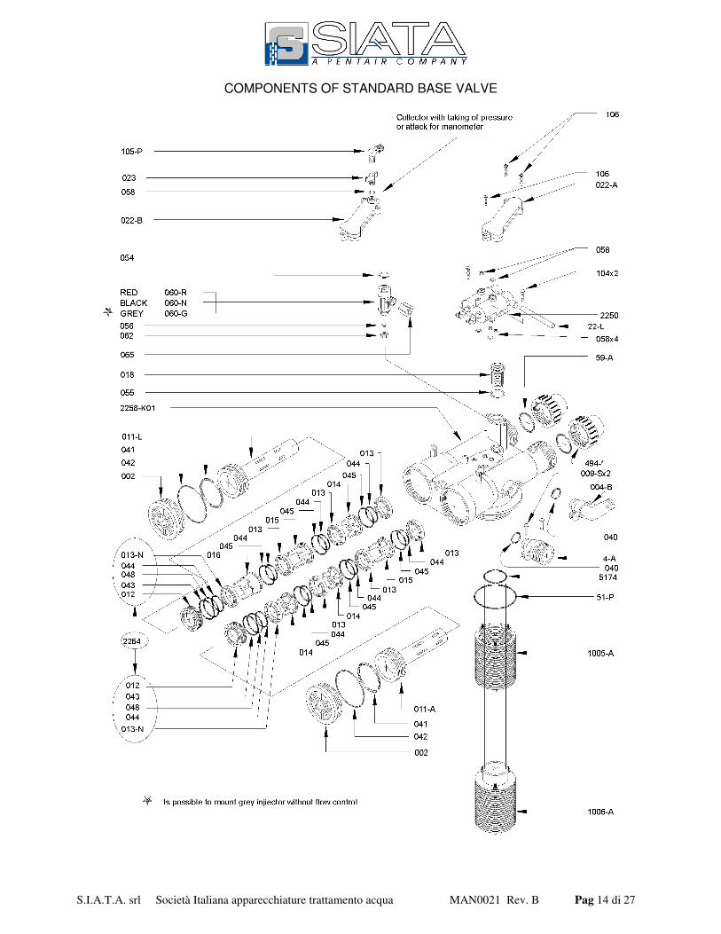
COMPONENTS OF STANDARD BASE VALVE
S.I.A.T.A. srl Società Italiana apparecchiature trattamento acqua MAN0021 Rev. B Pag 15 di 27
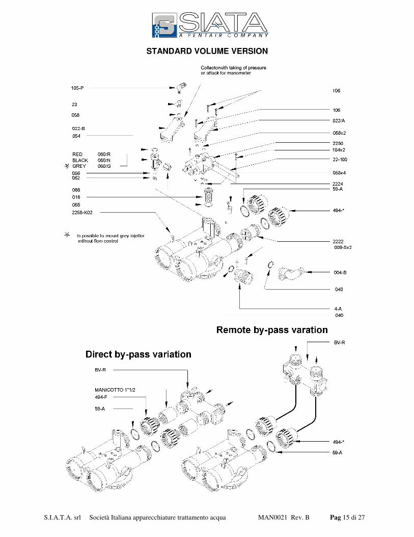
STANDARD VOLUME VERSION

S.I.A.T.A. srl Società Italiana apparecchiature trattamento acqua MAN0021 Rev. B Pag 16 di 27
STANDARD FILTRATION VERSION

S.I.A.T.A. srl Società Italiana apparecchiature trattamento acqua MAN0021 Rev. B Pag 17 di 27
DUPLEX AND DEMINERALISATION VALVE VERSION
S.I.A.T.A. srl Società Italiana apparecchiature trattamento acqua MAN0021 Rev. B Pag 18 di 27

S.I.A.T.A. srl Società Italiana apparecchiature trattamento acqua MAN0021 Rev. B Pag 19 di 27
S.I.A.T.A. srl Società Italiana apparecchiature trattamento acqua MAN0021 Rev. B Pag 20 di 27
S.I.A.T.A. srl Società Italiana apparecchiature trattamento acqua MAN0021 Rev. B Pag 21 di 27
AUTOMATIC BY-PASS FUNCTIONS
Proportional automatic by-pass functions consist in performances that facilitate system service withthe following functions:a) delivery of untreated water during regeneration phases;b) partial delivery of water under use and service when withdrawals momentarily are higher than
normal; Example: a momentary increase in water consumption creates a drop in pressure afterthe softening tank. The drop in water pressure as it comes out of the softener causes theautomatic by-pass valve to open partially, making up for the increased demand.
c) the by-pass has a mixer which, regulated to system functioning, obtains a residual hardnessvalue in treated water in conformity with norms.
d) in the event the system is equipped with a chlorine producer, it is advised to use a BVRPODby-pass with incoming and outgoing withdrawal, so as to perform the checks set out in DPR443.
e) the by-pass makes it possible to exclude the valve or the entire system without interruptingwater delivery.
S.I.A.T.A. srl Società Italiana apparecchiature trattamento acqua MAN0021 Rev. B Pag 22 di 27
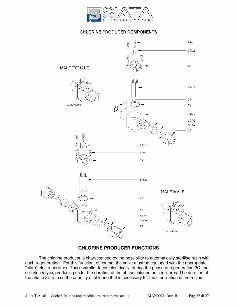
CHLORINE PRODUCER FUNCTIONS
The chlorine producer is characterised by the possibility to automatically sterilise resin witheach regeneration. For this function, of course, the valve must be equipped with the appropriate"cloro" electronic timer. This controller feeds electrically, during the phase of regeneration 2C, thecell electrolytic, producing so for the duration of the phase chlorine or is mixtures. The duration ofthe phase 2C rule so the quantity of chlorine that is necessary for the sterilisation of the resins.

S.I.A.T.A. srl Società Italiana apparecchiature trattamento acqua MAN0021 Rev. B Pag 23 di 27
PRECAUTIONS IN DISASSEMBLING "C" COLLECTOR
In disassembling the "C" collector, unscrew the screws slowly to avoid gripping between materialsand screws.Before remounting, carefully clean the hole and screws. Insert the screw in the hole and by hand,slowly turn it in direction "A" until reaching the beginning of the thread, then turn the screw indirection "B," still by hand, without forcing it.Using a screwdriver, slowly screw in direction "B" until tight; do not force. Always perform theseoperations using normal screwdrivers; do not use automatic screwdrivers.
MODIFICATION TO PERFORM IN CASE OF DAMAGE TO THREADED HOUSING OF "F" SELF-THREADING SCREWS
If during disassembly and reassembly of the "C" collector, the threads of the "F" screw housing,make a hole as indicated in "E," using a flat or squared large-grain file, 3 or 4 mm thick.Insert a 3M nut in this hole and replace the "F" screws with M3 "D" screws of the proper length(minimum 15 mm).
S.I.A.T.A. srl Società Italiana apparecchiature trattamento acqua MAN0021 Rev. B Pag 24 di 27
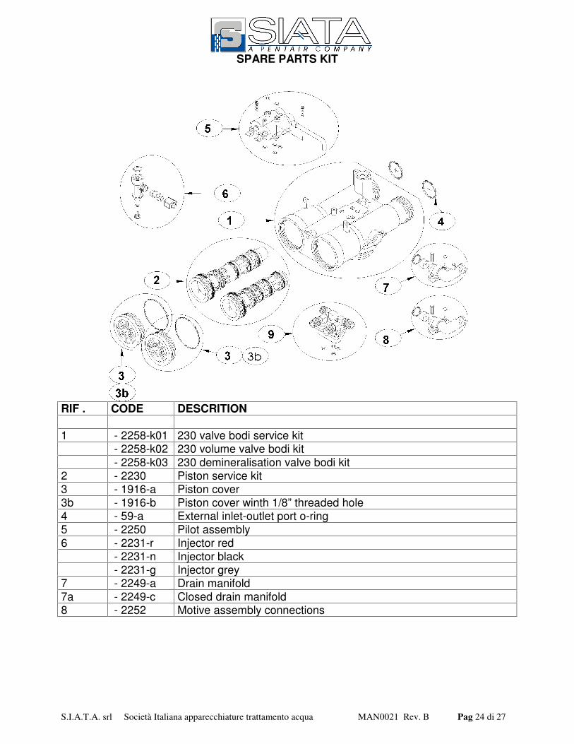
SPARE PARTS KIT
RIF . CODE DESCRITION
1 - 2258-k01 230 valve bodi service kit - 2258-k02 230 volume valve bodi kit - 2258-k03 230 demineralisation valve bodi kit
2 - 2230 Piston service kit3 - 1916-a Piston cover3b - 1916-b Piston cover winth 1/8” threaded hole4 - 59-a External inlet-outlet port o-ring5 - 2250 Pilot assembly6 - 2231-r Injector red
- 2231-n Injector black - 2231-g Injector grey
7 - 2249-a Drain manifold7a - 2249-c Closed drain manifold8 - 2252 Motive assembly connections
S.I.A.T.A. srl Società Italiana apparecchiature trattamento acqua MAN0021 Rev. B Pag 25 di 27
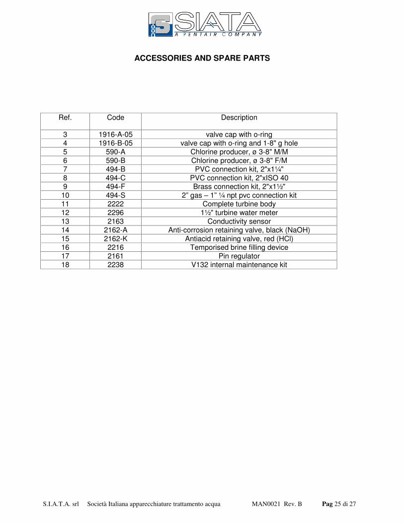
ACCESSORIES AND SPARE PARTS
Ref. Code Description
3 1916-A-05 valve cap with o-ring4 1916-B-05 valve cap with o-ring and 1-8" g hole5 590-A Chlorine producer, ø 3-8" M/M6 590-B Chlorine producer, ø 3-8" F/M7 494-B PVC connection kit, 2"x1¼"8 494-C PVC connection kit, 2"xISO 409 494-F Brass connection kit, 2"x1½"10 494-S 2” gas – 1” ¼ npt pvc connection kit11 2222 Complete turbine body12 2296 1½" turbine water meter13 2163 Conductivity sensor14 2162-A Anti-corrosion retaining valve, black (NaOH)15 2162-K Antiacid retaining valve, red (HCl)16 2216 Temporised brine filling device17 2161 Pin regulator18 2238 V132 internal maintenance kit
S.I.A.T.A. srl Società Italiana apparecchiature trattamento acqua MAN0021 Rev. B Pag 26 di 27
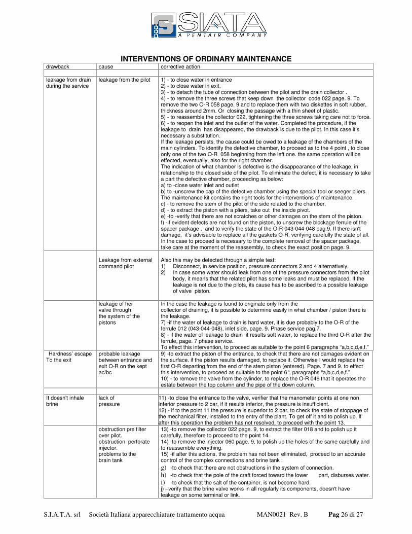
INTERVENTIONS OF ORDINARY MAINTENANCEdrawback cause corrective action
leakage from drainduring the service
leakage from the pilot 1) - to close water in entrance2) - to close water in exit.3) - to detach the tube of connection between the pilot and the drain collector .4) - to remove the three screws that keep down the collector code 022 page. 9. Toremove the two O-R 058 page. 9 and to replace them with two diskettes in soft rubber,thickness around 2mm. Or closing the passage with a thin sheet of plastic.5) - to reassemble the collector 022, tightening the three screws taking care not to force.6) - to reopen the inlet and the outlet of the water. Completed the procedure, if theleakage to drain has disappeared, the drawback is due to the pilot. In this case it’snecessary a substitution.If the leakage persists, the cause could be owed to a leakage of the chambers of themain cylinders. To identify the defective chamber, to proceed as to the 4 point , to closeonly one of the two O-R 058 beginning from the left one. the same operation will beeffected, eventually, also for the right chamber.The indication of what chamber is defective is the disappearance of the leakage, inrelationship to the closed side of the pilot. To eliminate the defect, it is necessary to takea part the defective chamber, proceeding as below:a) to -close water inlet and outletb) to -unscrew the cap of the defective chamber using the special tool or seeger pliers.The maintenance kit contains the right tools for the interventions of maintenance.c) - to remove the stem of the pilot of the side related to the chamber.d) - to extract the piston with a pliers, take out the inside pivot.e) -to -verify that there are not scratches or other damages on the stem of the piston.f) -if evident defects are not found on the piston, to unscrew the blockage ferrule of thespacer package , and to verify the state of the O-R 043-044-048 pag.9. If there isn'tdamage, it’s advisable to replace all the gaskets O-R, verifying carefully the state of all.In the case to proceed is necessary to the complete removal of the spacer package,take care at the moment of the reassembly, to check the exact position page. 9.
Leakage from externalcommand pilot
Also this may be detected through a simple test:1) Disconnect, in service position, pressure connectors 2 and 4 alternatively.2) In case some water should leak from one of the pressure connectors from the pilot
body, it means that the related pilot has some leaks and must be replaced. If theleakage is not due to the pilots, its cause has to be ascribed to a possible leakageof valve piston.
leakage of hervalve throughthe system of thepistons
In the case the leakage is found to originate only from thecollector of draining, it is possible to determine easily in what chamber / piston there isthe leakage.7) -if the water of leakage to drain is hard water, it is due probably to the O-R of theferrule 012 (043-044-048), inlet side, page. 9. Phase service pag.7.8) - if the water of leakage to drain it results soft water, to replace the third O-R after theferrule, page. 7 phase service.To effect this intervention, to proceed as suitable to the point 6 paragraphs “a,b,c,d,e,f.”
Hardness’ escapeTo the exit
probable leakagebetween entrance andexit O-R on the keptac/bc
9) -to extract the piston of the entrance, to check that there are not damages evident onthe surface. if the piston results damaged, to replace it. Otherwise I would replace thefirst O-R departing from the end of the stem piston (entered). Page. 7 and 9. to effectthis intervention, to proceed as suitable to the point 6°, paragraphs “a,b,c,d,e,f.”10) - to remove the valve from the cylinder, to replace the O-R 046 that it operates theestate between the top column and the pipe of the down column.
It doesn't inhalebrine
lack ofpressure
11) -to close the entrance to the valve, verifier that the manometer points at one noninferior pressure to 2 bar, if it results inferior, the pressure is insufficient.12) - if to the point 11 the pressure is superior to 2 bar, to check the state of stoppage ofthe mechanical filter, installed to the entry of the plant. To get off it and to polish up. Ifafter this operation the problem has not resolved, to proceed with the point 13.
obstruction pre filterover pilot.obstruction perforateinjector.problems to thebrain tank
13) -to remove the collector 022 page. 9, to extract the filter 018 and to polish up itcarefully, therefore to proceed to the point 14.14) -to remove the injector 060 page. 9, to polish up the holes of the same carefully andto reassemble everything.15) -if after this actions, the problem has not been eliminated, proceed to an accuratecontrol of the complex connections and brine tank :g) -to check that there are not obstructions in the system of connection.h) -to check that the pole of the craft forced toward the lower part, disburses water.i) -to check that the salt of the container, is not become hard.j) –verify that the brine valve works in all regularly its components, doesn't haveleakage on some terminal or link.
S.I.A.T.A. srl Società Italiana apparecchiature trattamento acqua MAN0021 Rev. B Pag 27 di 27