steel building the world - Marcegaglia Buildtech€¦ · Conductibilidad térmica λ: 0,043 W/mK...
80
steel building the world
Transcript of steel building the world - Marcegaglia Buildtech€¦ · Conductibilidad térmica λ: 0,043 W/mK...

steel building the world
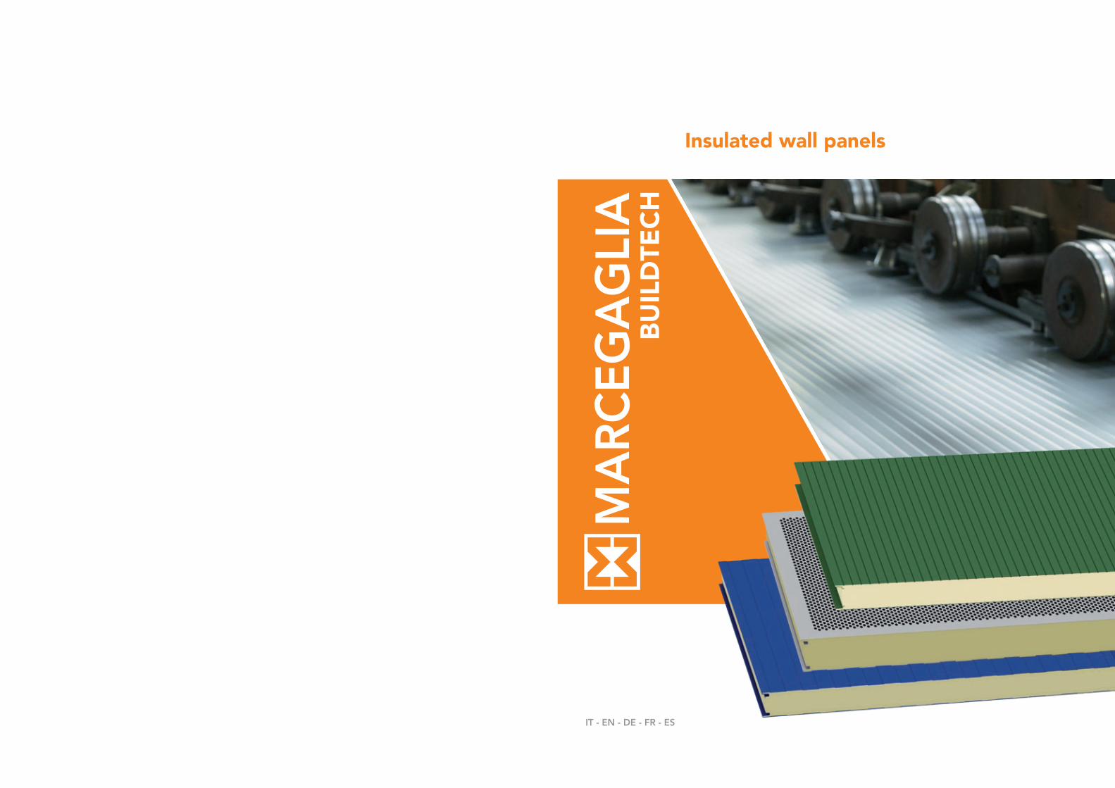
Insulated wall panels
IT - EN - DE - FR - ES

steel building the world

6 Marcegaglia Buildtech Marcegaglia Buildtech 7
Marcegaglia è un gruppo industriale leader mondiale nella tra-sformazione dell’acciaio, con 5,6 milioni di tonnellate lavorate ogni anno. Dalla prima trasformazione, nell’ambito della propria filiera produttiva controllata, Marcegaglia ricava la gamma più ampia al mondo di semilavorati e prodotti finiti in acciaio.
Marcegaglia is the leading industrial group worldwide in the steel process-ing sector, with a yearly output of 5.6 million tons. After first transforma-tion, within its controlled value chain Marcegaglia develops the world’s widest range of steel semi-products and finished goods.
Marcegaglia ist der weltweit führende Industriekonzern im Bereich Stahlum-wandlung mit jährlich 5,6 Millionen Tonnen verarbeitetem Stahl. Aus der ersten Umwandlung innerhalb der eigenen, kontrollierten Produktionskette erzeugt Marcegaglia das weltweit umfangreichste Sortiment an Halb- und Fertigerzeugnissen.
Marcegaglia est le groupe industriel leader mondial de la transformation de l’acier avec 5,6 millions de tonnes usinées chaque année. De la première trans-formation, dans sa propre filière de production contrôlée, Marcegaglia obtient la gamme de produits semi-ouvrés et de produits finis en acier la plus étendue du monde.
Marcegaglia es el grupo industrial líder mundial en la transformación del acero, con 5,6 millones de toneladas trabajadas cada año. Desde la primera transformación en el ámbito de su hilera productiva controlada, Marcegaglia obtiene la gama de semiproductos y productos acabados en acero más amplia a escala mundial.
La gamma di pannelli coibentati Marcegaglia Buildtech per parete con isolante in schiuma poliuretanica o in lana di roccia è parte della filiera produttiva certificata di semilavorati e prodotti finiti in acciaio per applicazione nel settore dell’edilizia civile e industriale anche con proprietà fonoassorbenti o specifici per camere fredde e celle frigori-fere. Studiati e ingegnerizzati per gli specifici utilizzi, i pannelli san-dwich coibentati per parete in acciaio preverniciato possono essere applicati in orizzontale o in verticale.
La produzione è interamente realizzata nel più grande e moderno sta-bilimento italiano specializzato di Pozzolo Formigaro (Nord Italia), recentemente ampliato e rinnovato con le ultime tecnologie produtti-ve per garantire qualità e innovazione di prodotto, e nello stabilimen-to di Praszka (Polonia).
The Marcegaglia Buildtech range of insulated wall panels with polyurethane foam or mineral wool insulation forms part of the certified production chain of unfinished and finished steel products for application in the civil and industrial construction sector, including types with sound-absorbing properties, or speci-fically for cold rooms and cold storage rooms. Designed and engineered for the specific uses, insulated precoated steel sandwich wall panels can be mounted horizontally or vertically.
They are entirely manufactured in Italy‘s largest, most modern specialist plant at Pozzolo Formigaro (northern Italy), recently expanded and renewed with the latest production technologies to guarantee product quality and innovation, and at the Praszka (Poland) plant.
Das Sortiment von Marcegaglia Buildtech an Isolierpaneelen mit Dämmschicht aus Polyurethanschaum oder Gesteinswolle für Wände ist Teil der zertifizierten Produktionskette von halbfertigen und fertigen Stahlerzeugnissen zur Anwen-dung im Zivil- und Industriebauwesen und beinhaltet auch Erzeugnisse mit schalldämmenden oder spezifischen Eigenschaften für Kühlräume bzw. Kühl-zellen. Die Sandwich-Isolierpaneele aus vorlackiertem Stahl für Wände wur-den speziell für die genannten Sonderanwendungen entworfen und ausgelegt und können sowohl horizontal als auch vertikal angebracht werden.
Die komplette Fertigung erfolgt im größten und modernsten italienischen Spe-zialwerk in Pozzolo Formigaro (Norditalien), das erst kürzlich erweitert und mit den neuesten Herstellungstechnologien ausgestattet wurde, um Qualität und Produktinnovation zu gewährleisten, sowie in dem Werk in Praszka (Po-len).
Pannelli coibentati per pareteInsulated wall panelsIsolierpaneele für WändePanneaux de bardage pour murPaneles aislantes para pared
La gamme de panneaux de bardage Marcegaglia Buildtech pour mur avec iso-lant en mousse de polyuréthane ou en laine de roche fait partie de la filière de production certifiée de produits semi-finis et finis en acier pour une application dans le secteur des constructions civiles et industrielles et offre également des propriétés d’isolation acoustiques ou spécifiques pour chambres froides et cel-lules frigorifiques. Étudiés et conçus pour des utilisations spécifiques, les pan-neaux sandwich de bardage pour mur en acier pré-verni peuvent être appliqués à l’horizontale ou à la verticale.
La production est entièrement réalisée dans le plus grand établissement italien moderne spécialisé de Pozzolo Formigaro (nord de l’Italie), agrandi dernière-ment et rénové selon les dernières technologies productives afin de garantir la qualité et l’innovation du produit, ainsi que dans l’établissement de Praszka (Pologne).
La gama de paneles aislantes Marcegaglia Buildtech para pared que contienen aislante a base de espuma de poliuretano o de lana de roca forma parte de la cadena de producción certificada de productos semiacabados y acabados de acero para aplicaciones en el sector de la construcción civil e industrial, tam-bién con propiedades de absorción del ruido o específicas para cámaras frías y frigoríficas. Estudiados y dotados de la tecnología necesaria para cada uso específico, los paneles sándwich aislantes para paredes, fabricados a base de acero prepintado pueden utilizarse en horizontal o vertical.
La producción se realiza íntegramente en la planta especializada italiana más grande y moderna de Pozzolo Formigaro (al norte de Italia), recientemente ampliada y renovada con las últimas tecnologías de producción para garan-tizar la calidad e innovación del producto, así como en la planta de Praszka (Polonia).

8 Marcegaglia Buildtech Marcegaglia Buildtech 9
SUPPORTIMetallic supportsSchalenSupportsSoportes
Acciaio zincato Sendzimir secondo EN 10143 ed EN 10346, con qualità S250GD
Preverniciati secondo EN 10169 (Coil Coating) in base alle norme ECCA ed EURONORME:
di produzione normale: - con rivestimento MP3 poliesteri
di produzione speciale: - con rivestimento MP5 poliesteri modificati/ poliuretanici- con rivestimento MP10 fluorocarbonici- con rivestimento MP20 poliuretanici/ poliammidici- con rivestimento MPHR
Acciaio zincato plastificato EN 10346
Alluminio naturale, preverniciato EN 485-2, EN 573-3, EN 11396
Rame, inox e secondo le necessità EN 1172, EN 1173, EN 1412
Sendzimir galvanized steel according to EN 10143, EN 10346, S250GD grade
Pre-painted steel according to EN 10169 (coil coating) and to ECCA norms and EURONORMS:
standard production: - with MP3 polyester coating
special production: - with MP5 modified polyester/polyurethane coating - with MP10 fluorocarbon coating - with MP20 polyurethane/polyamide coating- with MPHR coating
Plastic coated, galvanized steel EN 10346
Natural, pre-painted aluminium EN 485-2, EN 573-3, EN 11396
Copper, stainless steel or other materials upon request EN 1172, EN 1173, EN 1412
Sendzimir-verzinkter Stahl gemäß EN 10143 und EN 10346 in der Güte S250GD
Beschichteter Stahl gemäß EN 10169 (coil coating ) und nach ECCA Richtlinien und EURONORMEN:
normale Fertigung: - mit Polyesterbeschichtung (MP3)
Sonderfertigung: - mit geänderter Polyurethan-/ Polyesterbeschichtung (MP5)- mit Fluorocarbon- beschichtung (MP10)- mit Polyurethan-/ Polyamidbeschichtung (MP20)- mit MPHR-Beschichtung
Kunststoff beschichteter verzinkter Stahl nach EN 10346
Unbehandelter, vorgestrichener Aluminium nach EN 485, EN 573, EN 11396
Kupfer, Edelstahl je nach Anfrage gemäß EN 1172, EN 1173 und EN 1412
Acier galvanisé Sendzimir selon EN 10143 et EN 10346, avec qualité S250GD
Pré-vernis selon EN 10169 (Coil Coating) en fonction des normes ECCA et EURONORME:
de production normale: - avec revêtement MP3 en polyester
de production spéciale: - avec revêtement MPS en polyester modifié/ polyuréthane- avec revêtement MP10 en fluorocarbone- avec revêtement MP20 en polyuréthane/ polyamide- avec revêtement MPHR
Acier galvanisé plastifié EN 10346
Aluminium naturel, pré -vernis EN 485-2, EN 573-3, EN 11396
Cuivre, inox, et selon les besoins EN 1172, EN1173, EN 1412
Acero galvanizado Sendzimir según EN 10143 y EN 10346, con calidad S250GD
Prelacados según EN 10169 (Coil Coating) de acuerdo con las normas ECCA y EURONORME:
de producción normal: - con revestimiento MP3 poliésteres
de producción especial: - con revestimiento MP5 poliésteres modificados/ poliuretánicos- con revestimiento MP10 fluorocarbónicos- con revestimiento MP20 poliuretánicos/ poliamídicos- con revestimiento MPHR
Acero galvanizado plastificado EN 10346
Aluminio natural, prelacado EN 485-2, EN 573-3, EN 11396
Cobre, inox y según las necesidades EN 1172, EN 1173, EN 1412
COIBENTAZIONEInsulationIsolierungIsolantAislamiento térmico
Sono utilizzate formulazioni poliuretaniche esenti da CFC e HCFC che producono schiume isolanti anigroscopiche, antimuffa e ad alto contenuto di celle chiuse (>95%). Per le richieste di prestazione al fuoco, possono essere impiegate schiume con reazione al fuoco particolarmente performanti.
Conducibilità termica λ: 0,021 W/mK
Densità media totale: 35 - 40 kg/m3
We use CFC and HCFC FREE, polyurethane products that are capable of producing waterproof, mold-resistant insulating foams with a high percentage of closed cells (>95%). High-performance reactive fire resistant foams are available when greater fire resistance is required.
Thermic conductivity λ: 0,021 W/mK
Overall average density: 35 - 40 kg/m3
Es werden FCKW- und HCFC-freie Polyurethan-produkte verwendet, die einen isolierenden, nicht hygroskopischen Schaum bilden, dem Schimmel entgegen wirken und einen hohen Gehalt an geschlossenen Zellen bewahren (>95%). Was die Feuerleistungs-anforderungen angeht, kann Schaum mit beson-ders hoher Feuerfestig-keit benutzt werden.
Wärmeleitfähigkeit λ: 0,021 W/mK
mittlere Dichte:35 - 40 kg/m3
Formules utilisées à base de polyuréthane sans CFC ni HCFC produisant des mousses isolantes anigroscopiques, anti-moisissures et comportant plus de 95 % de cellules fermées. Des mousses offrant une réaction au feu particulièrement performante peuvent également être utilisées.
Conductibilité thermiqueλ: 0,021 W/mK
Densité moyenne totale:35 - 40 kg/m3
Se utilizan productos poliuretánicos libres de CFC y HCFC que producen espumas aislantes anhigroscópicas, antimoho y con elevado contenido de celdas cerradas (>95%). Para prestaciones contra el fuego, pueden utilizarse espumas con reacción al fuego particularmente válidas.
Conductibilidad térmicaλ: 0,021 W/mK
Densidad media total:35 - 40 kg/m3
Le lane di roccia impiegate sono di tipo biosolubile, anigroscopico, inimputrescibili e incombustibili (classe A1 europea di reazione al fuoco)
Conducibilità termica λ: 0,043 W/mK (correttamente misurata nella direzione delle fibre)
Densità media totale: 95 - 105 kg/m3
We use mineral wool that is biosoluble, waterproof, rot proof, and fire resistant (European Fire Resistance Rating A1)
Thermic conductivity λ: 0,043 W/mK(correctly measured in the fiber direction)
Overall average density: 95 - 105 kg/m3
Die verwendete Mineralwolle ist biologisch abbaubar, nicht hygroskopisch, praktisch unverrottbar und nicht brennbar (Europäische Klasse A1 in Bezug auf das Brandverhalten)
Wärmeleitfähigkeitλ: 0,043 W/mK(Korrekt in Faserrichtung gemessen)
Mittlere Dichte:95 - 105 kg/m3
Les laines de roche utilisées sont biosolubles, anigroscopiques, imputrescibles et incombustibles (classe A1 européenne de réaction au feu)
Conductibilité thermiqueλ: 0,043 W/mK(correctement mesurée dans le sens des fibres)
Densité moyenne totale:95 - 105 kg/m3
Las lanas de roca utilizadas son de tipo biosoluble, anhigroscópico, imputrescibles e incombustibles (clase A1 europea de reacción al fuego)
Conductibilidad térmicaλ: 0,043 W/mK(correctamente medida en la dirección de las fibras)
Densidad media total:95 - 105 kg/m3
Sia per il poliuretano che per la lanadi roccia, nelle schede prodotto sono indicate le trasmittanze termiche U calcolate secondo la norma EN ISO 6946. Per i soli pannelli soggetti a marcatura CE, sono indicate anche le trasmittanze termiche calcolate secondo la norma prodotto EN 14509.
The product data sheets for both the polyurethane and mineral wool indicate the heat transmittance, U, calculated according to EN ISO 6946. Data sheets for CE marked panels only also indicate the thermal transmittance calculated according to the product standard EN 14509.
In den Datenblättern sind sowohl für das Polyurethan als auch für die Mineralwolle die gemäß EN ISO 6946 berechneten Wärmedurchgangswerte (U-Werte) angegeben. Für die der CE-Kennzeichnung unterliegenden Paneele dagegen sind auch die gemäß EN 14509 berechneten Wärmedurchgangswerte angegeben.
Les transmittances thermiques U calculées selon la norme EN ISO 6946 sont indiquées sur les fiches produit du polyuréthane et de la laine de roche. Les transmittances thermiques calculées selon la norme EN 14509 sont également indiquées pour les panneaux soumis au label CE.
Tanto para el poliuretano como para la lana de roca, en las fichas del producto se indican las transmitancias térmicas U calculadas conforme a EN ISO 6946.Solo para los paneles sujetos a marcado CE, también se indican las transmitancias térmicas calculadas conforme a la norma producto EN 14509.
ADERENZAAdhesionAnhaftungAdhérenceAdherencia
Vengono usualmente considerate nella norma zone di non aderenza con dimensioni non superiori a 5% della superficie del pannello.Aderenza tra i supporti 0,10 N/mm2.
Non-adhesion zones are usually considered as normal with dimensions not exceeding 5% of the panel surface.Adherence between supports 0,10 N/mm2.
Gewöhnlich gelten die solche Bereiche als innerhalb der Norm, deren Nichthaftung Abmessungen von nicht mehr als 5% der Baulement-Oberfläche beträgt.Haftfestigkeit zwischen Trägern 0,10 N/mm2.
Des zones de non-adhérence, inférieures à 5% de la surface du panneau sont considérées comme conformes à la norme.Adhérence entre les supports 0,10 N/mm2.
Se consideran conformes con la norma aquellas zonas de “no adherencia” con dimensiones no superiores al 5% de la superficie del panel. Adherencia entre los soportes 0,10 N/mm2.
top a finirefinishing top coat
trattamento chimicochemical treatment
trattamento chimico chemical treatment
zincatura a caldohot dip galvanization
acciao laminato a freddo S250GDS250GD cold rolled steel
primer o back coatprimer or back coat
primerprimer
zincatura a caldohot dip galvanization
Specifiche tecniche - Pannelli coibentatiTechnical specifications - Insulated panels Spezifikationen - BauelementeSpécifications techniques - Panneaux isolantsEspecificaciones técnicas - Paneles aislantes
ACCIAIO AL CARBONIO PREVERNICIATO sec. EN 10169
PRE-PAINTED CARBON STEEL according to EN 10169

10 Marcegaglia Buildtech Marcegaglia Buildtech 11
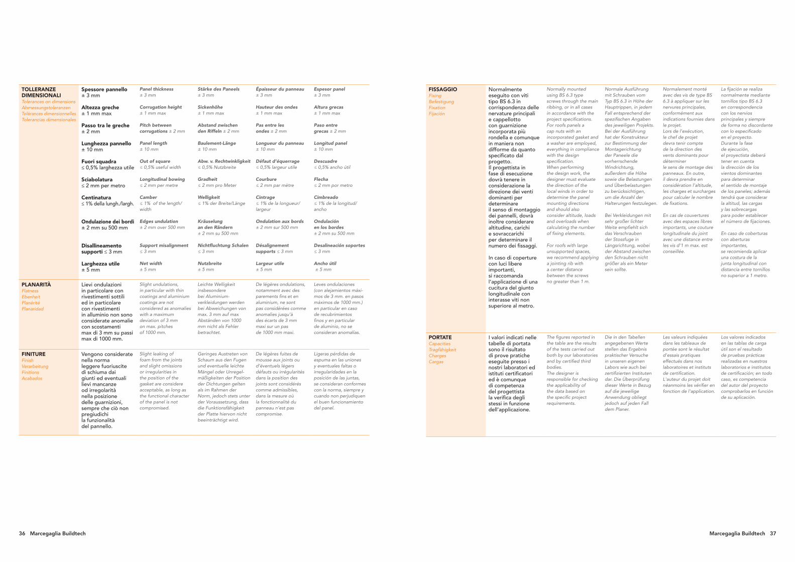
TOLLERANZE DIMENSIONALITolerances on dimensionsAbmessungstoleranzenTolérances dimensionnellesTolerancias dimensionales
Spessore pannello± 3 mm
Lunghezza pannello± 10 mm
Fuori squadra ≤ 0,5% larghezza utile
Sciabolatura≤ 2 mm per metro
Centinatura ≤ 1% della lungh./largh.
Ondulazione dei bordi ± 2 mm su 500 mm
Disallineamento supporti ≤ 3 mm
Larghezza utile ± 5 mm
Panel thickness± 3 mm
Panel length ± 10 mm
Out of square≤ 0,5% useful width
Longitudinal bowing≤ 2 mm per metre
Camber≤ 1% of the length/width
Edges undulation± 2 mm over 500 mm
Support misalignment≤ 3 mm
Net width± 5 mm
Stärke des Paneels± 3 mm
Baulement-Länge± 10 mm
Abw. v. Rechtwinkligkeit≤ 0,5% Nutzbreite
Gradheit≤ 2 mm pro Meter
Welligkeit≤ 1% der Breite/Länge
Kräuselung an den Rändern± 2 mm su 500 mm
Nichtfluchtung Schalen≤ 3 mm
Nutzbreite ± 5 mm
Épaisseur du panneau± 3 mm
Longueur du panneau± 10 mm
Défaut d’équerrage≤ 0,5% largeur utile
Courbure≤ 2 mm par mètre
Cintrage≤ 1% de la longueur/largeur
Ondulation aux bords± 2 mm sur 500 mm
Désalignement supports ≤ 3 mm
Largeur utile ± 5 mm
Espesor panel± 3 mm
Longitud panel ± 10 mm
Descuadre ≤ 0,5% ancho útil
Flecha ≤ 2 mm por metro
Cimbreado ≤ 1% de la longitud/ancho
Ondulación en los bordes ± 2 mm su 500 mm
Desalineación soportes ≤ 3 mm
Ancho útil ± 5 mm
PLANARITÀFlatnessEbenheitPlanéritéPlanaridad
Lievi ondulazioni in particolare con rivestimenti sottili ed in particolare con rivestimenti in alluminio non sono considerate anomalie con scostamenti max di 3 mm su passi max di 1000 mm.
Slight undulations, in particular with thin coatings and aluminium coatings are not considered as anomalies with a maximum deviation of 3 mm on max. pitches of 1000 mm.
Leichte Welligkeit insbesondere bei Aluminium-verkleidungen werden bei Abweichungen von max. 3 mm auf max Abständen von 1000 mm nicht als Fehler betrachtet.
De légères ondulations, notamment avec des parements fins et en aluminium, ne sont pas considérées comme anomalies jusqu’à des écarts de 3 mm maxi sur un pas de 1000 mm maxi.
Leves ondulaciones (con alejamientos máxi-mos de 3 mm. en pasos máximos de 1000 mm.) en particular en caso de recubrimientos finos y en particular de aluminio, no se consideran anomalías.
FINITUREFinishVerarbeitungFinitionsAcabados
Vengono considerate nella norma leggere fuoriuscite di schiuma dai giunti ed eventuali lievi mancanze od irregolarità nella posizione delle guarnizioni, sempre che ciò non pregiudichi la funzionalità del pannello.
Slight leaking of foam from the joints and slight omissions or irregularities in the position of the gasket are considere acceptable, as long as the functional character of the panel is not compromised.
Geringes Austreten von Schaum aus den Fugen und eventuelle leichte Mängel oder Unregel-mäßigkeiten der Position der Dichtungen gelten als im Rahmen der Norm, jedoch stets unter der Voraussetzung, dass die Funktionsfähigkeit der Platte hiervon nicht beeinträchtigt wird.
De légères fuites de mousse aux joints ou d’éventuels légers défauts ou irrégularités dans la position des joints sont considérés comme admissibles, dans la mesure où la fonctionnalité du panneau n’est pas compromise.
Ligeras pérdidas de espuma en las uniones y eventuales faltas o irregularidades en la posición de las juntas, se consideran conformes con la norma, siempre y cuando non perjudiquen el buen funcionamiento del panel.
FISSAGGIOFixingBefestigungFixationFijación
Normalmente eseguito con viti tipo BS 6.3 in corrispondenza delle nervature principali e comunque in maniera non difforme da quanto specificato dal progetto. Il progettista in fase di esecuzione dovrà tenere in considerazione la direzione dei venti dominanti per determinare il senso di montaggio dei pannelli, dovrà inoltre considerare altitudine, carichi e sovraccarichi per determinare il numero dei fissaggi.
Normally mounted using BS 6.3 type screws through the main ribbing, or in all cases in accordance with the project specifications. For roofs panels a cap nuts with an incorporated gasket and a washer are employed, everything in compliance with the design specification. When performing the design work, the designer must evaluate the direction of the local winds in order to determine the panel mounting directions and should also consider altitude, loads and overloads when calculating the number of fixing elements.
Normale Ausführung mit Schrauben vom Typ BS 6.3 in Höhe der Hauptrippen, in jedem Fall entsprechend der spezifischen Angaben des jeweiligen Projekts. Bei der Ausführung hat der Konstrukteur zur Bestimmung der Montagerichtung der Paneele die vorherrschende Windrichtung, außerdem die Höhe sowie die Belastungen und Überbelastungen zu berücksichtigen, um die Anzahl der Halterungen festzulegen.
Normalement monté avec des vis de type BS 6.3 à appliquer sur les nervures principales, conformément aux indications fournies dans le projet. Lors de l’exécution, le chef de projet devra tenir compte de la direction des vents dominants pour déterminer le sens de montage des panneaux. En outre, il devra prendre en considération l’altitude, les charges et surcharges pour calculer le nombre de fixations.
La fijación se realiza normalmente mediante tornillos tipo BS 6.3 en correspondencia con los nervios principales y siempre de forma no discordante con lo especificado en el proyecto. Durante la fase de ejecución, el proyectista deberá tener en cuenta la dirección de los vientos dominantes para determinar el sentido de montaje de los paneles; además tendrá que considerar la altitud, las cargas y las sobrecargas para poder establecer el número de fijaciones.
PORTATECapacitiesTragfähigkeitChargesCargas
I valori indicati nelle tabelle di portata sono il risultato di prove pratiche eseguite presso i nostri laboratori ed istituti certificatori ed è comunque di competenza del progettista la verifica degli stessi in funzione dell’applicazione.
The figures reported in the table are the results of the tests carried out both by our laboratories and by certified third bodies.The designer is responsible for checking the applicability of the data based on the specific project requirements.
Die in den Tabellen angegebenen Werte stellen das Ergebnis praktischer Versuche in unseren eigenen Labors wie auch bei zertifizierten Instituten dar. Die Überprüfung dieser Werte in Bezug auf die jeweilige Anwendung obliegt jedoch auf jeden Fall dem Planer.
Les valeurs indiquées dans les tableaux de portée sont le résultat d'essais pratiques effectués dans nos laboratoires et instituts de certification. L'auteur du projet doit néanmoins les vérifier en fonction de l'application.
Los valores indicados en las tablas de carga útil son el resultado de pruebas prácticas realizadas en nuestros laboratorios e institutos de certificación; en todo caso, es competencia del autor del proyecto comprobarlos en función de su aplicación.

Bs2d0
Pannelli metallici coibentati per pareti interne ed esterne, studiati per rispondere alle più svariate esigenze dell’edilizia civile ed industriale.
Insulated metal panels for indoor and outdoor walls, designed to satisfy the widest ranging civil and industrial building requirements.
Isolierte Baulemente für Innen- und Außenwände, für die unterschiedlichsten Anforderungen im Wohnungs- und Industriebau entwickelt.
Panneaux isolants à parements en tôle d’acier, destinés au bardage intérieur ou extérieur, étudiés afin de répondre aux exigences les plus diverses de la construction civile et industrielle.
Paneles metálicos aislantes para paredes internas y externas, concebidos con el fin de satisfacer las distintas exigencias del sector de la construcción civil e industrial.
Pannelli parete in poliuretanoPolyurethane wall panelsWandpaneele aus PolyurethanPanneaux bardage en polyuréthanePaneles pared de poliuretano
PR2 - PDD - PSS
PR2 - PDD - PSS ACCIAIO - STEEL
Spessore pannello
Panel thickness
Spessore supporto
Support thickness
Peso Weight U
Distanza fra gli appoggi in m - Supports spacing (m)
campata semplice - simple span campata multipla - multiple span
mm mm kg/m2
W/m2K 2 2,5 3 3,5 4 2 2,5 3 3,5 4 4,5 5EN
14509
EN
ISO 6946Carico massimo uniformemente distribuito in kN/m2 acciaio - Max load capacity kN/m2 steel
250,5/0,50,6/0,6
9,3110,98
0,78 0,751,00 0,55 1,55 0,85
1,07 0,59 1,66 0,91 0,62
300,4/0,40,5/0,50,6/0,6
7,839,50
11,170,66 0,63
0,76 0,41 1,00 0,63 0,38
1,50 0,80 0,50 1,98 1,25 0,75
1,61 0,86 0,54 2,15 1,34 0,80
350,4/0,40,5/0,50,6/0,6
8,02 9,69
11,360,57 0,55
0,86 0,51 0,33 1,17 0,79 0,49 0,30
1,70 1,00 0,65 2,30 1,55 0,96 0,60
1,82 1,07 0,70 0,50 2,55 1,66 1,03 0,64
400,4/0,40,5/0,50,6/0,6
8,21 9,88
11,550,50 0,48
1,01 0,73 0,48 0,29 1,52 0,96 0,66 0,47 0,33
2,00 1,43 0,95 0,58 0,40 3,00 1,90 1,30 0,92 0,65 0,45
2,15 1,53 1,02 0,62 0,43 3,12 2,05 1,39 0,98 0,70 0,48
500,4/0,40,5/0,50,6/0,6
8,5910,2611,93
0,41 0,39
1,14 0,89 0,66 0,45 0,33 1,95 1,29 0,91 0,68 0,48 0,33
2,25 1,75 1,30 0,88 0,65 3,85 2,55 1,79 1,34 0,95 0,65 0,50
2,40 1,87 1,39 0,94 0,70 4,00 2,80 1,92 1,44 1,02 0,70 0,54
600,4/0,40,5/0,50,6/0,6
8,9810,6412,31
0,34 0,33
1,37 1,12 0,86 0,61 0,46 2,33 1,62 1,17 0,91 0,66 0,41 0,30
2,70 2,20 1,70 1,20 0,90 4,60 3,20 2,30 1,80 1,30 0,80 0,60
2,90 2,40 1,82 1,28 0,96 4,80 3,38 2,48 1,93 1,39 0,86 0,64
800,5/0,50,6/0,6
11,4013,07
0,26 0,253,50 2,50 1,90 1,50 1,20 5,65 4,35 3,25 2,42 1,85 1,40 1,15
3,70 2,70 2,10 1,61 1,28 5,80 4,52 3,43 2,65 1,98 1,50 1,23
1000,5/0,50,6/0,6
12,1613,83
0,21 0,204,50 3,00 2,30 1,68 1,45 6,40 4,90 3,90 3,00 2,40 1,90 1,55
4,70 3,20 2,50 1,88 1,65 6,58 5,12 4,05 3,12 2,58 2,00 1,60
1200,5/0,50,6/0,6
12,9214,59
0,17 0,175,00 3,80 2,90 2,20 1,93 7,10 5,70 4,60 3,60 2,90 2,40 1,93
5,20 4,00 3,10 2,40 2,05 7,21 5,83 4,80 3,80 3,00 2,53 2,00
1500,5/0,50,6/0,6
14,1215,79
0,14 0,135,38 4,40 3,35 2,59 2,29 7,63 6,30 5,13 4,05 3,28 2,78 2,22
5,58 4,60 3,55 2,79 2,35 7,68 6,36 5,36 4,31 3,32 2,93 2,30
PR2 - PDD - PSS ALLUMINIO - ALUMINIUM
Spessore pannello
Panel thickness
Spessore supporto
Support thickness
Peso Weight U
Distanza fra gli appoggi in m - Supports spacing (m)
campata semplice - simple span campata multipla - multiple span
mm mm kg/m2 W/m2K 2 2,5 3 3,5 4 2 2,5 3 3,5 4 4,5 5
EN
14509
EN
ISO 6946Carico massimo uniformemente distribuito in kN/m2 alluminio - Max load capacity kN/m2 aluminium
25 0,6/0,6 4,40 0,79 0,75 0,75 0,40
30 0,6/0,6 4,59 0,66 0,64 0,70 1,10 0,62
35 0,6/0,6 4,78 0,57 0,55 0,90 0,50 1,40 0,75 0,45
40 0,6/0,6 4,97 0,51 0,49 1,20 0,70 0,40 1,75 1,00 0,62
50 0,6/0,6 5,35 0,41 0,39 1,65 1,00 0,60 2,05 1,55 1,00 0,62
60 0,6/0,6 5,73 0,34 0,33 1,80 1,40 0,80 0,40 2,23 1,80 1,30 0,90 0,60
80 0,6/0,6 6,49 0,26 0,25 2,15 1,80 1,20 0,80 0,58 2,50 2,10 1,80 1,20 0,90 0,70 0,40
100 0,6/0,6 7,25 0,21 0,20 2,45 2,10 1,50 1,10 0,80 3,00 2,60 2,20 1,60 1,28 0,80 0,65
CARATTERISTICHECharacteristicsEigenschaftenCaractéristiquesCaracterísticas
FrecciaF≤ 1/200 L
Spessori fuori standardmm 120/150
NotePD2, PDR e PLL producibili a richiesta. PSL e PLL disponibili con passo utile a 1155 mm, su richiesta.
DeflectionF≤ 1/200L
Non standard thicknessmm 120/150
NotesPD2, PDR and PLL can be produced on request. PSL and PLL available on request with 1155 mm pitch.
DurchbiegungF≤ 1/200L
Wandstärken in Sonderausführungmm 120/150
BemerkungenBezugsmaß für die Schraubenlänge
FlècheF≤ 1/200L
Épaisseurs hors normemm 120/150
NotesMesure de référence pour longueur de la vis
FlechaF≤ 1/200L
Espesores fuera de estándarmm 120/150
NotasMedida de referencia para longitud tornillos
Nastro adesivoAdhesive tape
CoibentazioneInsulation
Supporto metallicoMetallic support
GuarnizioneGasket
25 mm
1000 mm
91 mm
1000 mm
25 mm
1000 mm
Reazione al fuoco / schiuma PIR - Reaction to fire / PIR foam
spessore pannellopanel thickness
Euroclass spessore min. lamieramin. sheet thickness
30 - 150 B s2 d0 external 0.4 - internal 0.4
Il montaggio dei pannelli può avvenire in posa sia verticale sia orizzontale. Nel caso di posa orizzontale si raccomanda di posizionare i pannelli con il maschio verso l’alto. Panels may be mounted both vertically and horizontally. When mounting horizontally, it is recommended to install the panels with male facing up.
12 Marcegaglia Buildtech Marcegaglia Buildtech 13
PR2
PD
D
PSS
PDR F
N
PSS
FN
PDD FN - PSS FN - PDR FN ALLUMINIO - ALUMINIUM
Spessore pannello
Panel thickness
Spessore supporto
Support thickness
Peso Weight U
Distanza fra gli appoggi in m - Supports spacing (m)
campata semplice - simple span campata multipla - multiple span
mm mm kg/m2 W/m2K 2 2,5 3 3,5 4 2 2,5 3 3,5 4 4,5 5
EN
14509
EN
ISO 6946Carico massimo uniformemente distribuito in kN/m2 alluminio - Max load capacity kN/m2 aluminium
50 0,6/0,6 5,73 0,46 0,39 1,65 1,00 0,60 2,05 1,55 1,00 0,62
60 0,6/0,6 6,11 0,38 0,33 1,80 1,40 0,80 0,40 2,23 1,80 1,30 0,90 0,60
80 0,6/0,6 6,87 0,27 0,25 2,15 1,80 1,20 0,80 0,58 2,46 2,00 1,80 1,20 0,90 0,70 0,40
100 0,6/0,6 7,63 0,21 0,20 2,48 2,13 1,53 1,13 0,91 2,79 2,33 2,13 1,53 1,23 1,98 1,71
120 0,6/0,6 8,39 0,18 0,17 2,73 2,34 1,68 1,24 1,00 3,07 2,56 2,34 1,68 1,35 2,18 1,88
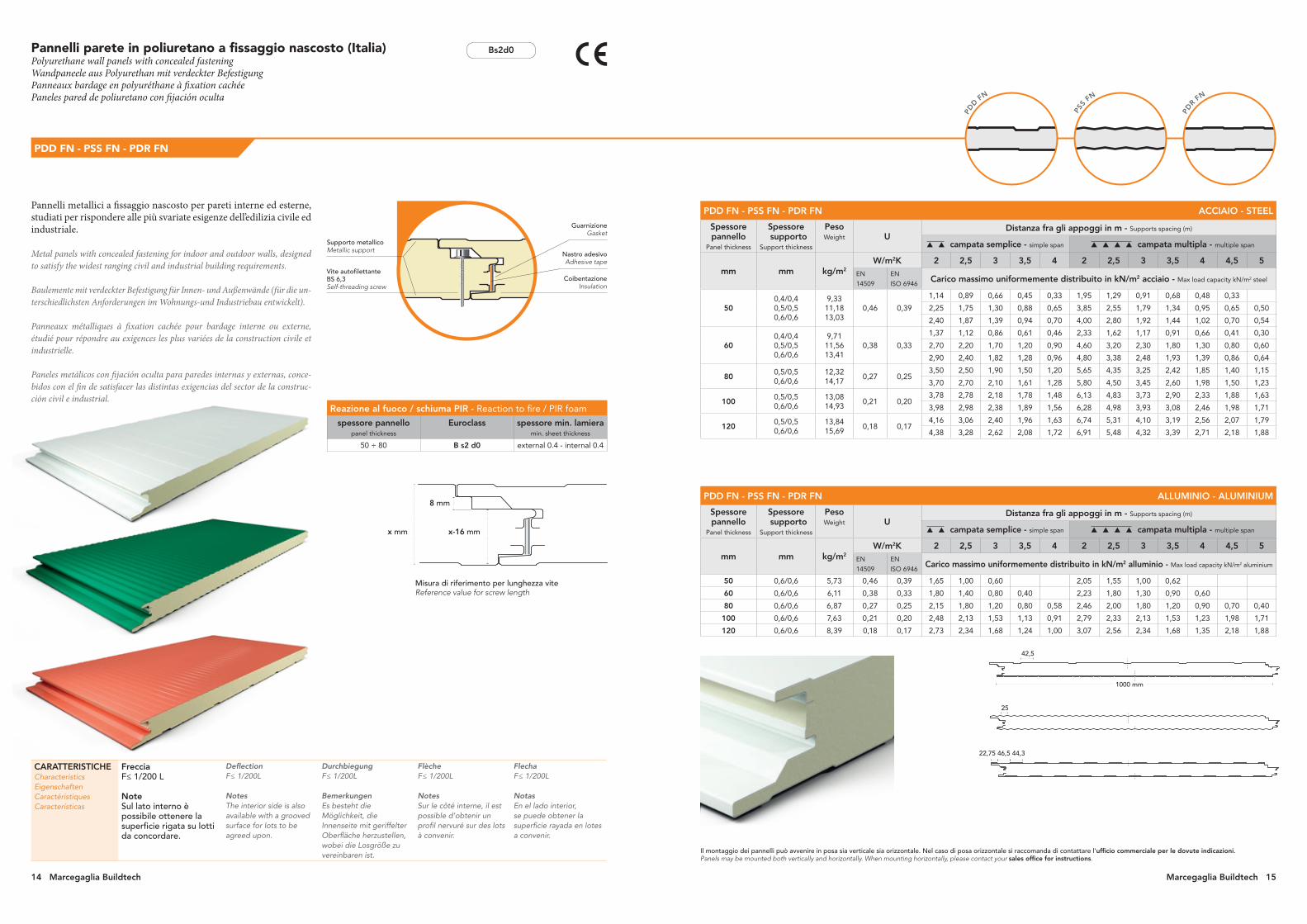
Pannelli metallici a fissaggio nascosto per pareti interne ed esterne, studiati per rispondere alle più svariate esigenze dell’edilizia civile ed industriale.
Metal panels with concealed fastening for indoor and outdoor walls, designed to satisfy the widest ranging civil and industrial building requirements.
Baulemente mit verdeckter Befestigung für Innen- und Außenwände (für die un-terschiedlichsten Anforderungen im Wohnungs-und Industriebau entwickelt).
Panneaux métalliques à fixation cachée pour bardage interne ou externe, étudié pour répondre au exigences les plus variées de la construction civile et industrielle.
Paneles metálicos con fijación oculta para paredes internas y externas, conce-bidos con el fin de satisfacer las distintas exigencias del sector de la construc-ción civil e industrial.
Pannelli parete in poliuretano a fissaggio nascosto (Italia)Polyurethane wall panels with concealed fasteningWandpaneele aus Polyurethan mit verdeckter BefestigungPanneaux bardage en polyuréthane à fixation cachéePaneles pared de poliuretano con fijación oculta
PDD FN - PSS FN - PDR FN
CARATTERISTICHECharacteristicsEigenschaftenCaractéristiquesCaracterísticas
FrecciaF≤ 1/200 L
NoteSul lato interno è possibile ottenere la superficie rigata su lotti da concordare.
DeflectionF≤ 1/200L
NotesThe interior side is also available with a grooved surface for lots to be agreed upon.
DurchbiegungF≤ 1/200L
BemerkungenEs besteht die Möglichkeit, die Innenseite mit geriffelter Oberfläche herzustellen, wobei die Losgröße zu vereinbaren ist.
FlècheF≤ 1/200L
NotesSur le côté interne, il est possible d’obtenir un profil nervuré sur des lots à convenir.
FlechaF≤ 1/200L
NotasEn el lado interior, se puede obtener la superficie rayada en lotes a convenir.
Nastro adesivoAdhesive tape
Vite autofilettante BS 6,3Self-threading screw
CoibentazioneInsulation
Supporto metallicoMetallic support
GuarnizioneGasket
PDD FN - PSS FN - PDR FN ACCIAIO - STEEL
Spessore pannello
Panel thickness
Spessore supporto
Support thickness
Peso Weight U
Distanza fra gli appoggi in m - Supports spacing (m)
campata semplice - simple span campata multipla - multiple span
mm mm kg/m2
W/m2K 2 2,5 3 3,5 4 2 2,5 3 3,5 4 4,5 5EN
14509
EN
ISO 6946Carico massimo uniformemente distribuito in kN/m2 acciaio - Max load capacity kN/m2 steel
500,4/0,40,5/0,50,6/0,6
9,33 11,1813,03
0,46 0,39
1,14 0,89 0,66 0,45 0,33 1,95 1,29 0,91 0,68 0,48 0,33
2,25 1,75 1,30 0,88 0,65 3,85 2,55 1,79 1,34 0,95 0,65 0,50
2,40 1,87 1,39 0,94 0,70 4,00 2,80 1,92 1,44 1,02 0,70 0,54
600,4/0,40,5/0,50,6/0,6
9,71 11,5613,41
0,38 0,33
1,37 1,12 0,86 0,61 0,46 2,33 1,62 1,17 0,91 0,66 0,41 0,30
2,70 2,20 1,70 1,20 0,90 4,60 3,20 2,30 1,80 1,30 0,80 0,60
2,90 2,40 1,82 1,28 0,96 4,80 3,38 2,48 1,93 1,39 0,86 0,64
800,5/0,50,6/0,6
12,3214,17
0,27 0,253,50 2,50 1,90 1,50 1,20 5,65 4,35 3,25 2,42 1,85 1,40 1,15
3,70 2,70 2,10 1,61 1,28 5,80 4,50 3,45 2,60 1,98 1,50 1,23
1000,5/0,50,6/0,6
13,0814,93
0,21 0,203,78 2,78 2,18 1,78 1,48 6,13 4,83 3,73 2,90 2,33 1,88 1,63
3,98 2,98 2,38 1,89 1,56 6,28 4,98 3,93 3,08 2,46 1,98 1,71
1200,5/0,50,6/0,6
13,8415,69
0,18 0,174,16 3,06 2,40 1,96 1,63 6,74 5,31 4,10 3,19 2,56 2,07 1,79
4,38 3,28 2,62 2,08 1,72 6,91 5,48 4,32 3,39 2,71 2,18 1,88
Misura di riferimento per lunghezza viteReference value for screw length
x mm x-16 mm
8 mm
Bs2d0
Reazione al fuoco / schiuma PIR - Reaction to fire / PIR foam
spessore pannellopanel thickness
Euroclass spessore min. lamieramin. sheet thickness
50 ÷ 80 B s2 d0 external 0.4 - internal 0.4
Il montaggio dei pannelli può avvenire in posa sia verticale sia orizzontale. Nel caso di posa orizzontale si raccomanda di contattare l’ufficio commerciale per le dovute indicazioni. Panels may be mounted both vertically and horizontally. When mounting horizontally, please contact your sales office for instructions.
PDD F
N
42,5
25
22,75 46,5 44,3
1000 mm
14 Marcegaglia Buildtech Marcegaglia Buildtech 15

Pannelli parete in poliuretano a fissaggio nascosto (Polonia)Polyurethane wall panels with concealed fasteningWandpaneele aus Polyurethan mit verdeckter BefestigungPanneaux bardage en polyuréthane à fixation cachéePaneles pared de poliuretano con fijación oculta
Bs2d0
PLL
FN PL
PSS
FN PL
Pannelli metallici a fissaggio nascosto per pareti interne ed esterne, studiati per rispondere alle più svariate esigenze dell’edilizia civile ed industriale.
Metal panels with concealed fastening for indoor and outdoor walls, designed to satisfy the widest ranging civil and industrial building requirements.
Baulemente mit verdeckter Befestigung für Innen- und Außenwände (für die un-terschiedlichsten Anforderungen im Wohnungs-und Industriebau entwickelt).
Panneaux métalliques à fixation cachée pour bardage interne ou externe, étudié pour répondre au exigences les plus variées de la construction civile et industrielle.
Paneles metálicos con fijación oculta para paredes internas y externas, conce-bidos con el fin de satisfacer las distintas exigencias del sector de la construc-ción civil e industrial.
PDD FN PL - PSS FN PL - PLL FN PL
CARATTERISTICHECharacteristicsEigenschaftenCaractéristiquesCaracterísticas
FrecciaF≤ 1/200 L
NoteSul lato interno è possibile ottenere la superficie rigata su lotti da concordare.
DeflectionF≤ 1/200L
NotesThe interior side is also available with a grooved surface for lots to be agreed upon.
DurchbiegungF≤ 1/200L
BemerkungenEs besteht die Möglichkeit, die Innenseite mit geriffelter Oberfläche herzustellen, wobei die Losgröße zu vereinbaren ist.
FlècheF≤ 1/200L
NotesSur le côté interne, il est possible d’obtenir un profil nervuré sur des lots à convenir.
FlechaF≤ 1/200L
NotasEn el lado interior, se puede obtener la superficie rayada en lotes a convenir.
Nastro adesivoAdhesive tape
CoibentazioneInsulation
Supporto metallicoMetallic support
GuarnizioneGasket
44,3 mm 46,5 mm
1000 mm
1000 mm
25 mm
1000 mm
Reazione al fuoco / schiuma PIR - Reaction to fire / PIR foam
spessore pannellopanel thickness
Euroclass spessore min. lamieramin. sheet thickness
50 ÷ 80 B s2 d0 external 0.5 - internal 0.5
Il montaggio dei pannelli può avvenire in posa sia verticale sia orizzontale. Nel caso di posa orizzontale si raccomanda di contattare l’ufficio commerciale per le dovute indicazioni. Panels may be mounted both vertically and horizontally. When mounting horizontally, please contact your sales office for instructions.
PDD
FN PL
PDD FN PL - PSS FN PL - PLL FN PL ACCIAIO - STEEL
Spessore pannello
Panel thickness
Spessore supporto
Support thickness
Peso Weight U
Distanza fra gli appoggi in m - Supports spacing (m)
campata semplice - simple span
mm mm kg/m2
W/m2K 2,1 2,4 2,7 3 3,3 3,6 3,9 4,2 4,5 4,8 5,1 5,4 5,7 6,0
EN
14509
EN
ISO 6946Carico massimo uniformemente distribuito in kN/m2 acciaio
Max load capacity daN/m2 steel
60 0,5/0,5 11,10 0,38 0,33 2,60 2,30 2,00 1,70 1,40 1,14 0,960,80 0,67 0,57 0,47 0,37 0,29
0,78 0,59 0,44 0,32 0,23
80 0,5/0,5 11,90 0,27 0,25 3,30 2,70 2,26 1,90 1,66 1,44 1,26 1,08 0,92 0,800,70 0,61 1,77 0,46
0,68 0,58 0,49 0,42
100 0,5/0,5 12,70 0,21 0,20 3,58 2,98 2,54 2,18 1,94 1,72 1,54 1,32 1,14 0,99 0,87 0,76 0,67 0,59
PDD FN PL - PSS FN PL - PLL FN PL ALLUMINIO - ALUMINIUM
Spessore pannello
Panel thickness
Spessore supporto
Support thickness
Peso Weight U
Distanza fra gli appoggi in m - Supports spacing (m)
campata multipla - multiple span
mm mm kg/m2
W/m2K 2,1 2,4 2,7 3 3,3 3,6 3,9 4,2 4,5 4,8 5,1 5,4 5,7 6,0
EN
14509
EN
ISO 6946Carico massimo uniformemente distribuito in kN/m2 acciaio
Max load capacity daN/m2 steel
60 0,5/0,5 11,10 0,38 0,33 3,27 2,76 2,36 2,04 1,78 1,56 1,37 1,10 0,80 0,68 0,61 0,55 0,50 0,45
80 0,5/0,5 11,90 0,27 0,25 3,84 3,31 2,88 2,53 2,24 1,96 1,67 1,40 1,25 1,13 1,02 0,93 0,84
100 0,5/0,5 12,70 0,21 0,20 3,73 3,23 2,79 2,44 2,15 1,88 1,73 1,56 1,42 1,29 1,18
16 Marcegaglia Buildtech Marcegaglia Buildtech 17
LISC
IO
• PFL
DO
GAT
O • PFD
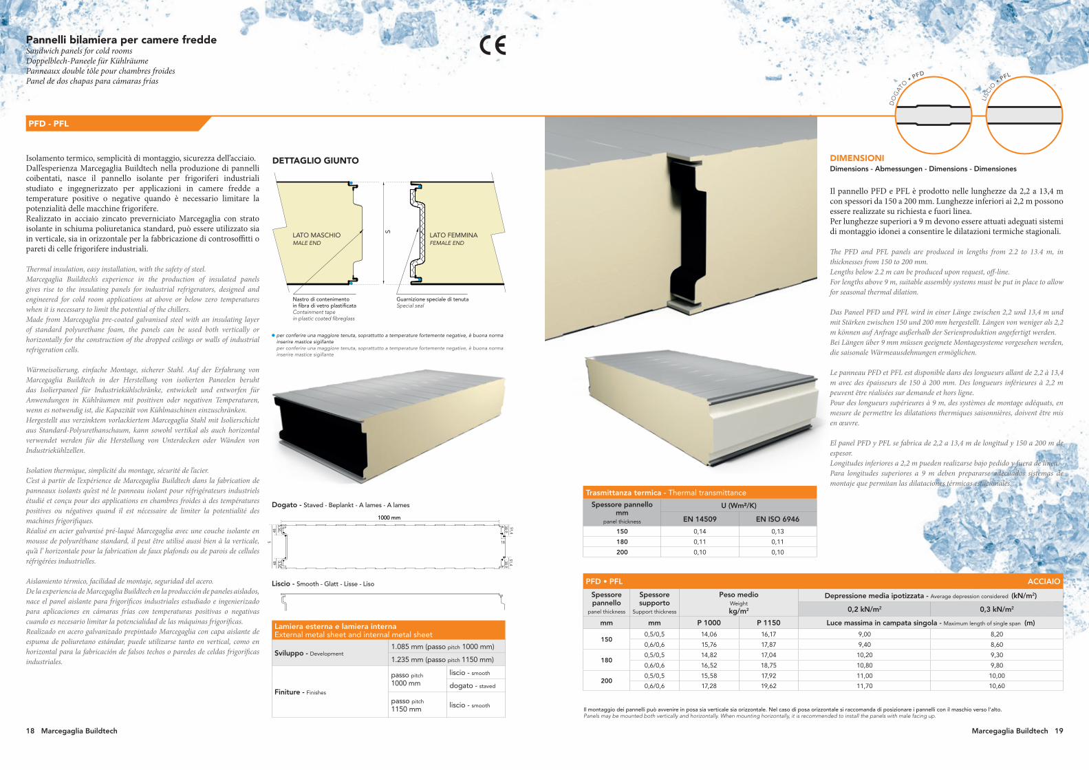
Pannelli bilamiera per camere fredde Sandwich panels for cold rooms Doppelblech-Paneele für KühlräumePanneaux double tôle pour chambres froidesPanel de dos chapas para cámaras frías
PFD - PFL
Isolamento termico, semplicità di montaggio, sicurezza dell’acciaio.Dall’esperienza Marcegaglia Buildtech nella produzione di pannelli coibentati, nasce il pannello isolante per frigoriferi industriali studiato e ingegnerizzato per applicazioni in camere fredde a temperature positive o negative quando è necessario limitare la potenzialità delle macchine frigorifere. Realizzato in acciaio zincato preverniciato Marcegaglia con strato isolante in schiuma poliuretanica standard, può essere utilizzato sia in verticale, sia in orizzontale per la fabbricazione di controsoffitti o pareti di celle frigorifere industriali.
Thermal insulation, easy installation, with the safety of steel.Marcegaglia Buildtech’s experience in the production of insulated panels gives rise to the insulating panels for industrial refrigerators, designed and engineered for cold room applications at above or below zero temperatures when it is necessary to limit the potential of the chillers.Made from Marcegaglia pre-coated galvanised steel with an insulating layer of standard polyurethane foam, the panels can be used both vertically or horizontally for the construction of the dropped ceilings or walls of industrial refrigeration cells.
Wärmeisolierung, einfache Montage, sicherer Stahl. Auf der Erfahrung von Marcegaglia Buildtech in der Herstellung von isolierten Paneelen beruht das Isolierpaneel für Industriekühlschränke, entwickelt und entworfen für Anwendungen in Kühlräumen mit positiven oder negativen Temperaturen, wenn es notwendig ist, die Kapazität von Kühlmaschinen einzuschränken. Hergestellt aus verzinktem vorlackiertem Marcegaglia Stahl mit Isolierschicht aus Standard-Polyurethanschaum, kann sowohl vertikal als auch horizontal verwendet werden für die Herstellung von Unterdecken oder Wänden von Industriekühlzellen.
Isolation thermique, simplicité du montage, sécurité de l’acier.C’est à partir de l’expérience de Marcegaglia Buildtech dans la fabrication de panneaux isolants qu’est né le panneau isolant pour réfrigérateurs industriels étudié et conçu pour des applications en chambres froides à des températures positives ou négatives quand il est nécessaire de limiter la potentialité des machines frigorifiques. Réalisé en acier galvanisé pré-laqué Marcegaglia avec une couche isolante en mousse de polyuréthane standard, il peut être utilisé aussi bien à la verticale, qu’à l’ horizontale pour la fabrication de faux plafonds ou de parois de cellules réfrigérées industrielles.
Aislamiento térmico, facilidad de montaje, seguridad del acero.De la experiencia de Marcegaglia Buildtech en la producción de paneles aislados, nace el panel aislante para frigoríficos industriales estudiado e ingenierizado para aplicaciones en cámaras frías con temperaturas positivas o negativas cuando es necesario limitar la potencialidad de las máquinas frigoríficas.Realizado en acero galvanizado prepintado Marcegaglia con capa aislante de espuma de poliuretano estándar, puede utilizarse tanto en vertical, como en horizontal para la fabricación de falsos techos o paredes de celdas frigoríficas industriales.
Il montaggio dei pannelli può avvenire in posa sia verticale sia orizzontale. Nel caso di posa orizzontale si raccomanda di posizionare i pannelli con il maschio verso l’alto. Panels may be mounted both vertically and horizontally. When mounting horizontally, it is recommended to install the panels with male facing up.
Trasmittanza termica - Thermal transmittance
Spessore pannello mm
panel thickness
U (Wm²/K)
EN 14509 EN ISO 6946
150 0,14 0,13
180 0,11 0,11
200 0,10 0,10
PFD • PFL ACCIAIO
Spessore pannello
panel thickness
Spessore supporto
Support thickness
Peso medio Weight
kg/m2
Depressione media ipotizzata - Average depression considered (kN/m2)
0,2 kN/m2 0,3 kN/m2
mm mm P 1000 P 1150 Luce massima in campata singola - Maximum length of single span (m)
1500,5/0,5 14,06 16,17 9,00 8,20
0,6/0,6 15,76 17,87 9,40 8,60
1800,5/0,5 14,82 17,04 10,20 9,30
0,6/0,6 16,52 18,75 10,80 9,80
2000,5/0,5 15,58 17,92 11,00 10,00
0,6/0,6 17,28 19,62 11,70 10,60
Lamiera esterna e lamiera internaExternal metal sheet and internal metal sheet
Sviluppo - Development1.085 mm (passo pitch 1000 mm)
1.235 mm (passo pitch 1150 mm)
Finiture - Finishes
passo pitch
1000 mmliscio - smooth
dogato - staved
passo pitch
1150 mm liscio - smooth
DIMENSIONI Dimensions - Abmessungen - Dimensions - Dimensiones
Il pannello PFD e PFL è prodotto nelle lunghezze da 2,2 a 13,4 m con spessori da 150 a 200 mm. Lunghezze inferiori ai 2,2 m possono essere realizzate su richiesta e fuori linea. Per lunghezze superiori a 9 m devono essere attuati adeguati sistemi di montaggio idonei a consentire le dilatazioni termiche stagionali.
The PFD and PFL panels are produced in lengths from 2.2 to 13.4 m, in thicknesses from 150 to 200 mm.Lengths below 2.2 m can be produced upon request, off-line.For lengths above 9 m, suitable assembly systems must be put in place to allow for seasonal thermal dilation.
Das Paneel PFD und PFL wird in einer Länge zwischen 2,2 und 13,4 m und mit Stärken zwischen 150 und 200 mm hergestellt. Längen von weniger als 2,2 m können auf Anfrage außerhalb der Serienproduktion angefertigt werden. Bei Längen über 9 mm müssen geeignete Montagesysteme vorgesehen werden, die saisonale Wärmeausdehnungen ermöglichen.
Le panneau PFD et PFL est disponible dans des longueurs allant de 2,2 à 13,4 m avec des épaisseurs de 150 à 200 mm. Des longueurs inférieures à 2,2 m peuvent être réalisées sur demande et hors ligne. Pour des longueurs supérieures à 9 m, des systèmes de montage adéquats, en mesure de permettre les dilatations thermiques saisonnières, doivent être mis en œuvre.
El panel PFD y PFL se fabrica de 2,2 a 13,4 m de longitud y 150 a 200 m de espesor.Longitudes inferiores a 2,2 m pueden realizarse bajo pedido y fuera de línea.Para longitudes superiores a 9 m deben prepararse adecuados sistemas de montaje que permitan las dilataciones térmicas estacionales.
S
Dogato - Staved - Beplankt - A lames - A lames
1000 mm1000 mm
51,44848
35,5
35,5
51,438,9
38,9
18
Liscio - Smooth - Glatt - Lisse - Liso
DETTAGLIO GIUNTO
per conferire una maggiore tenuta, soprattutto a temperature fortemente negative, è buona norma inserire mastice sigillanteper conferire una maggiore tenuta, soprattutto a temperature fortemente negative, è buona norma inserire mastice sigillante
LATO MASCHIO
Guarnizione speciale di tenutaSpecial seal
S
LATO FEMMINA
Nastro di contenimento in fibra di vetro plastificataContainment tape in plastic coated fibreglass
MALE END FEMALE END
18 Marcegaglia Buildtech Marcegaglia Buildtech 19
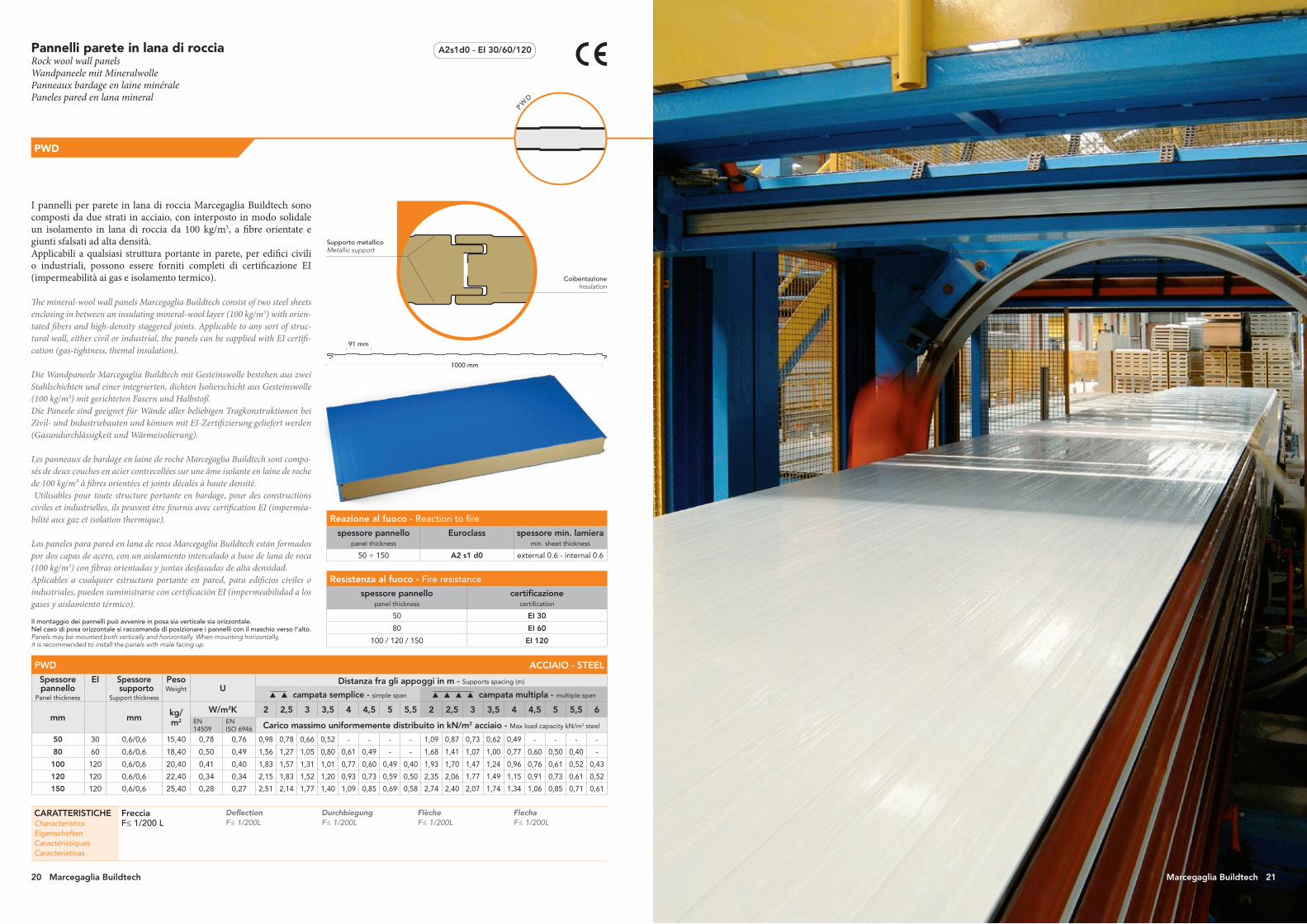
I pannelli per parete in lana di roccia Marcegaglia Buildtech sono composti da due strati in acciaio, con interposto in modo solidale un isolamento in lana di roccia da 100 kg/m3, a fibre orientate e giunti sfalsati ad alta densità. Applicabili a qualsiasi struttura portante in parete, per edifici civili o industriali, possono essere forniti completi di certificazione EI (impermeabilità ai gas e isolamento termico).
The mineral-wool wall panels Marcegaglia Buildtech consist of two steel sheets enclosing in between an insulating mineral-wool layer (100 kg/m3) with orien-tated fibers and high-density staggered joints. Applicable to any sort of struc-tural wall, either civil or industrial, the panels can be supplied with EI certifi-cation (gas-tightness, themal insulation).
Die Wandpaneele Marcegaglia Buildtech mit Gesteinswolle bestehen aus zwei Stahlschichten und einer integrierten, dichten Isolierschicht aus Gesteinswolle (100 kg/m3) mit gerichteten Fasern und Halbstoß. Die Paneele sind geeignet für Wände aller beliebigen Tragkonstruktionen bei Zivil- und Industriebauten und können mit EI-Zertifizierung geliefert werden (Gasundurchlässigkeit und Wärmeisolierung).
Les panneaux de bardage en laine de roche Marcegaglia Buildtech sont compo-sés de deux couches en acier contrecollées sur une âme isolante en laine de roche de 100 kg/m³ à fibres orientées et joints décalés à haute densité. Utilisables pour toute structure portante en bardage, pour des constructions civiles et industrielles, ils peuvent être fournis avec certification EI (imperméa-bilité aux gaz et isolation thermique).
Los paneles para pared en lana de roca Marcegaglia Buildtech están formados por dos capas de acero, con un aislamiento intercalado a base de lana de roca (100 kg/m3) con fibras orientadas y juntas desfasadas de alta densidad. Aplicables a cualquier estructura portante en pared, para edificios civiles o industriales, pueden suministrarse con certificación EI (impermeabilidad a los gases y aislamiento térmico).
Pannelli parete in lana di roccia Rock wool wall panelsWandpaneele mit MineralwollePanneaux bardage en laine minéralePaneles pared en lana mineral
PWD
CoibentazioneInsulation
Supporto metallicoMetallic support
CARATTERISTICHECharacteristicsEigenschaftenCaractéristiquesCaracterísticas
FrecciaF≤ 1/200 L
DeflectionF≤ 1/200L
DurchbiegungF≤ 1/200L
FlècheF≤ 1/200L
FlechaF≤ 1/200L
PW
D
A2s1d0 - EI 30/60/120
Reazione al fuoco - Reaction to fire
spessore pannellopanel thickness
Euroclass spessore min. lamieramin. sheet thickness
50 ÷ 150 A2 s1 d0 external 0.6 - internal 0.6
Resistenza al fuoco - Fire resistance
spessore pannellopanel thickness
certificazionecertification
50 EI 30
80 EI 60
100 / 120 / 150 EI 120
PWD ACCIAIO - STEEL
Spessore pannello
Panel thickness
EI Spessore supporto
Support thickness
Peso Weight U
Distanza fra gli appoggi in m - Supports spacing (m)
campata semplice - simple span campata multipla - multiple span
mm mm kg/m2
W/m2K 2 2,5 3 3,5 4 4,5 5 5,5 2 2,5 3 3,5 4 4,5 5 5,5 6EN 14509
EN ISO 6946 Carico massimo uniformemente distribuito in kN/m2 acciaio - Max load capacity kN/m2 steel
50 30 0,6/0,6 15,40 0,78 0,76 0,98 0,78 0,66 0,52 - - - - 1,09 0,87 0,73 0,62 0,49 - - - -
80 60 0,6/0,6 18,40 0,50 0,49 1,56 1,27 1,05 0,80 0,61 0,49 - - 1,68 1,41 1,07 1,00 0,77 0,60 0,50 0,40 -
100 120 0,6/0,6 20,40 0,41 0,40 1,83 1,57 1,31 1,01 0,77 0,60 0,49 0,40 1,93 1,70 1,47 1,24 0,96 0,76 0,61 0,52 0,43
120 120 0,6/0,6 22,40 0,34 0,34 2,15 1,83 1,52 1,20 0,93 0,73 0,59 0,50 2,35 2,06 1,77 1,49 1,15 0,91 0,73 0,61 0,52
150 120 0,6/0,6 25,40 0,28 0,27 2,51 2,14 1,77 1,40 1,09 0,85 0,69 0,58 2,74 2,40 2,07 1,74 1,34 1,06 0,85 0,71 0,61
91 mm
1000 mm
Il montaggio dei pannelli può avvenire in posa sia verticale sia orizzontale. Nel caso di posa orizzontale si raccomanda di posizionare i pannelli con il maschio verso l’alto. Panels may be mounted both vertically and horizontally. When mounting horizontally, it is recommended to install the panels with male facing up.
Marcegaglia Buildtech 2120 Marcegaglia Buildtech Marcegaglia Buildtech 21

PW
D-F
Pannelli in lana di roccia con proprietà fonoassorbenti e fonoisolanti, composti da due strati in acciaio con interposto in modo solidale un isolamento in lana di roccia a fibre orientate e giunti sfalsati ad alta densità. Applicabili a strutture nelle quali siano richieste elevate proprietà di isolamento acustico, possono essere forniti completi di certificazione.
Rock wool panels with sound-absorbing and soundproofing properties, com-prising two layers of steel with a rigidly anchored high-density rock wool fibre insulating layer with staggered joints between them. Suitable for installation on structures in which high levels of soundproofing are required, can be supplied complete with certification.
Bauelemente aus Mineralwolle mit schallabsorbierenden und schallisolieren-den Eigenschaften, bestehend aus zwei Stahlschichten und einer einheitlich dazwischengelegten Isolierungslage aus dichter Mineralwolle mit orientierten Fasern und Halbstoß. Anwendbar bei Strukturen, bei denen eine besonders hohe Schallisolierung erfordert wird. Können mit Zertifikat geliefert werden.
Panneaux en laine minérale aux propriétés insonorisantes et phono-isolantes comprenant deux couches en acier et, intercalé de façon solidaire, une couche isolante en laine minérale à fibres orientées et joints décalés à haute densité. Utilisables pour tout structure à hautes propriétés insonorisantes, ils peuvent être fournis avec certification.
Paneles de lana mineral con propiedades fonoabsorbentes y fonoaislantes, compuestos de dos capas de acero que llevan intercalado de modo solidario un aislamiento de lana mineral de fibras orientadas y juntas escalonadas de alta densidad.Aplicables a estructuras que requieran elevadas propiedades de aislamiento acústico, se pueden suministrar provistos de certificación.
Pannelli parete fonoassorbente Sound-absorbing wall panels with acoustic performanceSchallabsorbierende Wandelemente Panneaux bardage insonorisantePaneles pared fonoabsorbente
PWD-F
PWD-F ACCIAIO - STEEL
Spessore pannello
Panel thickness
Spessore supporto
Support thickness
Peso Weight U
Distanza fra gli appoggi in m - Supports spacing (m)
campata semplice - simple span campata multipla - multiple span
mm mm kg/m2 W/m2K 2 2,5 3 3,5 4 4,5 5 5,5 2 2,5 3 3,5 4 4,5 5 5,5 6
EN 14509 EN ISO 6946 Carico massimo uniformemente distribuito in kN/m2 acciaio - Max load capacity kN/m2 steel
50 0,6/0,6 13,30 0,78 0,76 0,78 0,62 0,52 0,41 - - - - 0,87 0,69 0,58 0,49 0,39 - - - -
80 0,6/0,6 16,30 0,50 0,49 1,24 1,01 0,84 0,64 0,48 0,39 - - 1,34 1,12 0,85 0,80 0,61 0,48 0,40 0,32 -
100 0,6/0,6 18,30 0,41 0,40 1,46 1,25 1,04 0,80 0,61 0,48 0,39 0,32 1,54 1,36 1,17 0,99 0,76 0,60 0,48 0,41 0,34
120 0,6/0,6 20,30 0,34 0,34 1,72 1,46 1,21 0,96 0,74 0,58 0,47 0,40 1,88 1,64 1,41 1,19 0,92 0,72 0,58 0,48 0,41
150 0,6/0,6 23,30 0,28 0,27 2,00 1,70 1,41 1,12 0,86 0,68 0,55 0,46 2,19 1,92 1,65 1,39 1,07 0,84 0,68 0,56 0,48
CoibentazioneInsulation
Foratura R4T6 • Rapporto vuoto/pieno 37%R4T6 Drilling • Solid/void ratio 37%
Supporto metallicoMetallic support
CARATTERISTICHECharacteristicsEigenschaftenCaractéristiquesCaracterísticas
FrecciaF≤ 1/200 L
DeflectionF≤ 1/200L
DurchbiegungF≤ 1/200L
FlècheF≤ 1/200L
FlechaF≤ 1/200L
1000 mm
Il montaggio dei pannelli può avvenire in posa sia verticale sia orizzontale. Nel caso di posa orizzontale si raccomanda di posizionare i pannelli con il maschio verso l’alto. Panels may be mounted both vertically and horizontally. When mounting horizontally, it is recommended to install the panels with male facing up.
Assorbimento acusticoSound absorption
Isolamento acusticoSound insulation
Spessore Thickness mm α
W
ClasseClass
Rw (dB)
50 1,00
A
33
80 1,00 33
100 0,95 34
120 1,00 36
Marcegaglia Buildtech 2322 Marcegaglia Buildtech

Pannelli coibentati metallici per pareti interne ed esterne specificamente studiati per garantire il massimo isolamento termico degli ambienti interni di containers ad uso abitativo.
Metal insulated panels for indoor and outdoor walls, specifically designed to guarantee the highest possible thermal insulation for the interiors of container homes.
Isolierpaneele aus Metall für Innen- und Außenwände, speziell zur Gewähr-leistung der höchstmöglichen Wärmeisolierung der Innenräume von Wohn-containern ausgelegt.
Panneaux de bardage métalliques pour murs internes et externes, spécialement étudiés pour garantir une isolation thermique maximale des pièces internes des containers habitables.
Paneles aislantes metálicos para paredes interiores y exteriores pensados espe-cíficamente para garantizar el máximo aislamiento térmico de los ambientes interiores de contenedores para uso habitacional.
Bs3d0Pannelli parete per container abitativiWall panels for container homesWandpaneele für WohncontainerPanneaux mur pour containers habitablesPaneles de pared para contenedores habitables
PR2 - PDD - PLL
PR2 - PDD - PLL ACCIAIO - STEEL
Spessore pannello
Panel thickness
Spessore supporto
Support thickness
Peso Weight U
Distanza fra gli appoggi in m - Supports spacing (m)
campata semplice - simple span campata multipla - multiple span
mm mm kg/m2
W/m2K 2 2,5 3 3,5 4 2 2,5 3 3,5 4 4,5 5EN
14509
EN
ISO 6946Carico massimo uniformemente distribuito in kN/m2 acciaio - Max load capacity kN/m2 steel
250,5/0,50,6/0,6
9,3110,98
0,78 0,751,00 0,55 1,55 0,85
1,07 0,59 1,66 0,91 0,62
300,4/0,40,5/0,50,6/0,6
7,839,50
11,170,66 0,63
0,76 0,41 1,00 0,63 0,38
1,50 0,80 0,50 1,98 1,25 0,75
1,61 0,86 0,54 2,15 1,34 0,80
350,4/0,40,5/0,50,6/0,6
8,02 9,69
11,360,57 0,55
0,86 0,51 0,33 1,17 0,79 0,49 0,30
1,70 1,00 0,65 2,30 1,55 0,96 0,60
1,82 1,07 0,70 0,50 2,55 1,66 1,03 0,64
400,4/0,40,5/0,50,6/0,6
8,21 9,88
11,550,50 0,48
1,01 0,73 0,48 0,29 1,52 0,96 0,66 0,47 0,33
2,00 1,43 0,95 0,58 0,40 3,00 1,90 1,30 0,92 0,65 0,45
2,15 1,53 1,02 0,62 0,43 3,12 2,05 1,39 0,98 0,70 0,48
500,4/0,40,5/0,50,6/0,6
8,5910,2611,93
0,41 0,39
1,14 0,89 0,66 0,45 0,33 1,95 1,29 0,91 0,68 0,48 0,33
2,25 1,75 1,30 0,88 0,65 3,85 2,55 1,79 1,34 0,95 0,65 0,50
2,40 1,87 1,39 0,94 0,70 4,00 2,80 1,92 1,44 1,02 0,70 0,54
600,4/0,40,5/0,50,6/0,6
8,9810,6412,31
0,34 0,33
1,37 1,12 0,86 0,61 0,46 2,33 1,62 1,17 0,91 0,66 0,41 0,30
2,70 2,20 1,70 1,20 0,90 4,60 3,20 2,30 1,80 1,30 0,80 0,60
2,90 2,40 1,82 1,28 0,96 4,80 3,38 2,48 1,93 1,39 0,86 0,64
800,5/0,50,6/0,6
11,4013,07
0,26 0,253,50 2,50 1,90 1,50 1,20 5,65 4,35 3,25 2,42 1,85 1,40 1,15
3,70 2,70 2,10 1,61 1,28 5,80 4,52 3,43 2,65 1,98 1,50 1,23
1000,5/0,50,6/0,6
12,1613,83
0,21 0,204,50 3,00 2,30 1,68 1,45 6,40 4,90 3,90 3,00 2,40 1,90 1,55
4,70 3,20 2,50 1,88 1,65 6,58 5,12 4,05 3,12 2,58 2,00 1,60
1200,5/0,50,6/0,6
12,9214,59
0,17 0,175,00 3,80 2,90 2,20 1,93 7,10 5,70 4,60 3,60 2,90 2,40 1,93
5,20 4,00 3,10 2,40 2,05 7,21 5,83 4,80 3,80 3,00 2,53 2,00
1500,5/0,50,6/0,6
14,1215,79
0,14 0,135,38 4,40 3,35 2,59 2,29 7,63 6,30 5,13 4,05 3,28 2,78 2,22
5,58 4,60 3,55 2,79 2,35 7,68 6,36 5,36 4,31 3,32 2,93 2,30
PR2 - PDD - PLL ALLUMINIO - ALUMINIUM
Spessore pannello
Panel thickness
Spessore supporto
Support thickness
Peso Weight U
Distanza fra gli appoggi in m - Supports spacing (m)
campata semplice - simple span campata multipla - multiple span
mm mm kg/m2 W/m2K 2 2,5 3 3,5 4 2 2,5 3 3,5 4 4,5 5
EN
14509
EN
ISO 6946Carico massimo uniformemente distribuito in kN/m2 alluminio - Max load capacity kN/m2 aluminium
25 0,6/0,6 4,40 0,79 0,75 0,75 0,40
30 0,6/0,6 4,59 0,66 0,64 0,70 1,10 0,62
35 0,6/0,6 4,78 0,57 0,55 0,90 0,50 1,40 0,75 0,45
40 0,6/0,6 4,97 0,51 0,49 1,20 0,70 0,40 1,75 1,00 0,62
50 0,6/0,6 5,35 0,41 0,39 1,65 1,00 0,60 2,05 1,55 1,00 0,62
60 0,6/0,6 5,73 0,34 0,33 1,80 1,40 0,80 0,40 2,23 1,80 1,30 0,90 0,60
80 0,6/0,6 6,49 0,26 0,25 2,15 1,80 1,20 0,80 0,58 2,50 2,10 1,80 1,20 0,90 0,70 0,40
100 0,6/0,6 7,25 0,21 0,20 2,45 2,10 1,50 1,10 0,80 3,00 2,60 2,20 1,60 1,28 0,80 0,65
CARATTERISTICHECharacteristicsEigenschaftenCaractéristiquesCaracterísticas
FrecciaF≤ 1/200 L
Spessori fuori standardmm 120/150
NotePD2, PDR e PLL producibili a richiesta. PSL e PLL disponibili con passo utile a 1155 mm, su richiesta.
DeflectionF≤ 1/200L
Non standard thicknessmm 120/150
NotesPD2, PDR and PLL can be produced on request. PSL and PLL available on request with 1155 mm pitch.
DurchbiegungF≤ 1/200L
Wandstärken in Sonderausführungmm 120/150
BemerkungenBezugsmaß für die Schraubenlänge
FlècheF≤ 1/200L
Épaisseurs hors normemm 120/150
NotesMesure de référence pour longueur de la vis
FlechaF≤ 1/200L
Espesores fuera de estándarmm 120/150
NotasMedida de referencia para longitud tornillos
Nastro adesivoAdhesive tape
CoibentazioneInsulation
Supporto metallicoMetallic support
GuarnizioneGasket
25 mm
1000 mm
91 mm
1000 mm
Reazione al fuoco / schiuma PIR - Reaction to fire / PIR foam
spessore pannellopanel thickness
Euroclass spessore min. lamieramin. sheet thickness
30 - 150 B s2 d0 external 0.4 - internal 0.4
Il montaggio dei pannelli può avvenire in posa sia verticale sia orizzontale. Nel caso di posa orizzontale si raccomanda di posizionare i pannelli con il maschio verso l’alto. Panels may be mounted both vertically and horizontally. When mounting horizontally, it is recommended to install the panels with male facing up.
1000 mm
PR2
PD
D
PLL
Marcegaglia Buildtech 2524 Marcegaglia Buildtech
* simile al * similar to
rosso tegola tile red
M 4104
avorio chiaro light ivory
RAL 1015 *
grigio ombra umbra grey
RAL 7022 *
grigio antracite anthracite grey
RAL 7016 *
verde reseda reseda green
RAL 6011 *
verde muschio moss green
RAL 6005 *
blu grigiastro grey blue
RAL 5008 *
blu genziana gentian blue
RAL 5010 *
rosso Siena “Siena” red
M 4301
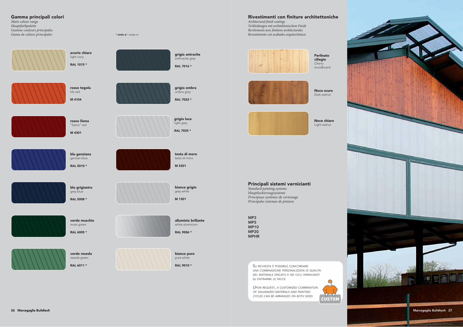
Principali sistemi verniciantiStandard painting systems Hauptlackierungssysteme Principaux systèmes de vernissage Principales sistemas de pintura
Noce chiaroLight walnut
Noce scuroDark walnut
Perlinato ciliegioCherry woodboard
grigio luce light grey
RAL 7035 *
testa di moro testa di moro
M 5301
bianco grigio grey white
M 1301
bianco puropure white
RAL 9010 *
alluminio brillantewhite aluminium
RAL 9006 *
Su richieSta è poSSibile concordare una combinazione perSonalizzata di qualità del materiale zincato e dei cicli vernicianti Su entrambe le facce
Upon reqUest, a cUstomized combination of galvanized materials and painting cycles can be arranged on both sides
MP3MP5MP10MP20MPHR
Gamma principali coloriMain colour range Hauptfarbpalette Gamme couleurs principales Gama de colores principales
Rivestimenti con finiture architettonicheArchitectural finish coatingsVerkleidungen mit architektonischem FinishRevêtements avec finitions architecturalesRevestimiento con acabados arquitectónicos
26 Marcegaglia Buildtech Marcegaglia Buildtech 2726 Marcegaglia Buildtech

Insulated roofing panels
IT - EN - DE - FR - ES
28 Marcegaglia Buildtech

steel building the world

Marcegaglia è un gruppo industriale leader mondiale nella tra-sformazione dell’acciaio, con 5,6 milioni di tonnellate lavorate ogni anno. Dalla prima trasformazione, nell’ambito della propria filiera produttiva controllata, Marcegaglia ricava la gamma più ampia al mondo di semilavorati e prodotti finiti in acciaio.
Marcegaglia is the leading industrial group worldwide in the steel process-ing sector, with a yearly output of 5.6 million tons. After first transforma-tion, within its controlled value chain Marcegaglia develops the world’s widest range of steel semi-products and finished goods.
Marcegaglia ist der weltweit führende Industriekonzern im Bereich Stahlum-wandlung mit jährlich 5,6 Millionen Tonnen verarbeitetem Stahl. Aus der ersten Umwandlung innerhalb der eigenen, kontrollierten Produktionskette erzeugt Marcegaglia das weltweit umfangreichste Sortiment an Halb- und Fertigerzeugnissen.
Marcegaglia est le groupe industriel leader mondial de la transformation de l’acier avec 5,6 millions de tonnes usinées chaque année. De la première trans-formation, dans sa propre filière de production contrôlée, Marcegaglia obtient la gamme de produits semi-ouvrés et de produits finis en acier la plus étendue du monde.
Marcegaglia es el grupo industrial líder mundial en la transformación del acero, con 5,6 millones de toneladas trabajadas cada año. Desde la primera transformación en el ámbito de su hilera productiva controlada, Marcegaglia obtiene la gama de semiproductos y productos acabados en acero más amplia a escala mundial.
Pannelli coibentati per coperturaInsulated roofing panelsIsolierpaneele für AbdeckungenPanneaux de bardage pour couverturePaneles aislantes para cubierta
La gamma di pannelli coibentati Marcegaglia Buildtech per coper-tura con isolante in schiuma poliuretanica o in lana di roccia è parte della filiera produttiva certificata di semilavorati e prodotti finiti in acciaio per applicazione nel settore dell’edilizia civile e industria-le anche con proprietà fonoassorbenti e in sostituzione della tradi-zionale copertura a coppo combinando la valenza estetica a quella dell’acciaio.
Studiati e ingegnerizzati per gli specifici utilizzi, i pannelli per co-pertura Marcegaglia Buildtech sono interamente realizzati nel più grande e moderno stabilimento italiano specializzato di Pozzolo Formigaro (Nord Italia), recentemente ampliato e rinnovato con le ultime tecnologie produttive per garantire qualità e innovazione di prodotto, e nello stabilimento di Praszka (Polonia).
The Marcegaglia Buildtech range of insulated roofing panels with polyurethane foam or rock wool insulation forms part of the certified production chain of unfinished and finished steel products for the civil and industrial construction sector, including sound-absorbing types or designs for use as an alternative to traditional roofing tiles, combining an attractive appearance with the benefits of steel.
Designed and engineered for their specific intended uses, Marcegaglia Build-tech roofing panels are entirely manufactured in Italy‘s largest, most modern specialist plant at Pozzolo Formigaro (northern Italy), recently expanded and renewed with the latest production technologies to guarantee product quality and innovation, and at the Praszka (Poland) plant.
Das Sortiment von Marcegaglia Buildtech an Isolierpaneelen mit Dämmschicht aus Polyurethanschaum oder Gesteinswolle für Abdeckungen ist Teil der zer-tifizierten Produktionskette von halbfertigen und fertigen Stahlerzeugnissen zur Anwendung im Zivil- und Industriebauwesen, auch mit schallisolierenden Eigenschaften und anstelle der traditionellen Ziegelbedachung, wobei der äs-thetische Aspekt mit den Vorteilen von Stahl kombiniert wird.
Die Abdeckpaneele wurden speziell für Sonderanwendungen entworfen und ausgelegt; ihre komplette Fertigung erfolgt im größten und modernsten itali-enischen Spezialwerk in Pozzolo Formigaro (Norditalien), das erst kürzlich erweitert und mit den neuesten Herstellungstechnologien ausgestattet wurde, um die Qualität und Produktinnovation zu gewährleisten, sowie in dem Werk in Praszka (Polen).
La gamme de panneaux de bardage Marcegaglia Buildtech pour couverture avec isolant en mousse de polyuréthane ou en laine de roche fait partie de la filière de production certifiée de produits semi-finis et finis en acier pour une application dans le secteur des constructions civiles et industrielles ; elle offre également des propriétés d’isolation acoustiques et peut être utilisée en rem-placement de la couverture traditionnelle en tuiles, associant ainsi la valeur esthétique à celle de l’acier.
Étudiés et conçus pour des utilisations spécifiques, les panneaux pour couver-ture Marcegaglia Buildtech sont entièrement réalisés dans le plus grand étab-lissement italien moderne spécialisé de Pozzolo Formigaro (nord de l’Italie), agrandi dernièrement et rénové selon les dernières technologies productives afin de garantir la qualité et l’innovation du produit, ainsi que dans l‘établissement de Praszka (Pologne).
La gama de paneles aislantes Marcegaglia Buildtech para cubierta que conti-enen aislante a base de espuma de poliuretano o de lana de roca forma parte de la cadena de producción certificada de productos semiacabados y acabados de acero para aplicaciones en el sector de la construcción civil e industrial, tambi-én con propiedades de absorción del ruido y como sustitución de la tradicional cubierta de teja, combinando el valor estético y el del acero.
Estudiados y dotados de la tecnología necesaria para cada uso específico, los paneles para cubierta Marcegaglia Buildtech se fabrican íntegramente en la planta especializada italiana más grande y moderna de Pozzolo Formigaro (al norte de Italia), recientemente ampliada y renovada con las últimas tecnologías de producción para garantizar la calidad e innovación del producto, así como en la planta de Praszka (Polonia).
32 Marcegaglia Buildtech Marcegaglia Buildtech 33

SUPPORTIMetallic supportsSchalenSupportsSoportes
Acciaio zincato Sendzimir secondo EN 10143 ed EN 10346con qualità S250GD
Preverniciati secondo EN 10169 (Coil Coating) in base alle norme ECCA ed EURONORME:
di produzione normale: - con rivestimento MP3 poliesteri
di produzione speciale: - con rivestimento MP5 poliesteri modificati/ poliuretanici- con rivestimento MP10 fluorocarbonici- con rivestimento MP20 poliuretanici/ poliammidici- con rivestimento MPHR
Acciaio zincato plastificato EN 10346
Alluminio naturale, preverniciato EN 485-2, EN 573-3, EN 11396
Rame, inox e secondo le necessità EN 1172, EN 1173, EN 1412
Sendzimir galvanized steel according to EN 10143, EN 10346, S250GD grade
Pre-painted steel according to EN 10169 (coil coating) and to ECCA norms and EURONORMS:
standard production: - with MP3 polyester coating
special production: - with MP5 modified polyester/polyurethane coating - with MP10 fluorocarbon coating - with MP20 polyurethane/polyamide coating- with MPHR coating
Plastic coated, galvanized steel EN 10346
Natural, pre-painted aluminium EN 485-2, EN 573-3, EN 11396
Copper, stainless steel or other materials upon request EN 1172, EN 1173, EN 1412
Sendzimir-verzinkter Stahl gemäß EN 10143 und EN 10346 in der Güte S250GD
Beschichteter Stahl gemäß EN 10169 (coil coating ) und nach ECCA Richtlinien und EURONORMEN:
normale Fertigung: - mit Polyesterbeschichtung (MP3)
Sonderfertigung: - mit geänderter Polyurethan-/ Polyesterbeschichtung (MP5)- mit mit Fluorocarbon- beschichtung (MP10)- mit Polyurethan-/ Polyamidbeschichtung (MP20)- mit MPHR-Beschichtung
Kunststoff beschichteter verzinkter Stahl nach EN 10346
Unbehandelter, vorgestrichener Aluminium nach EN 485, EN 573, EN 11396
Kupfer, Edelstahl je nach Anfrage gemäß EN 1172, EN 1173 und EN 1412
Acier galvanisé Sendzimir selon EN 10143 et EN 10346, avec qualité S250GD
Pré-vernis selon EN 10169 (Coil Coating) en fonction des normes ECCA et EURONORME:
de production normale: - avec revêtement MP3 en polyester
de production spéciale: - avec revêtement MPS en polyester modifié/ polyuréthane- avec revêtement MP10 en fluorocarbone- avec revêtement MP20 en polyuréthane/ polyamide- avec revêtement MPHR
Acier galvanisé plastifié EN 10346
Aluminium naturel, pré -vernis EN 485-2, EN 573-3, EN 11396
Cuivre, inox, et selon les besoins EN 1172, EN1173, EN 1412
Acero galvanizado Sendzimir según EN 10143 y EN 10346, con calidad S250GD
Prelacados según EN 10169 (Coil Coating) de acuerdo con las normas ECCA y EURONORME:
de producción normal: - con revestimiento MP3 poliésteres
de producción especial: - con revestimiento MP5 poliésteres modificados/ poliuretánicos- con revestimiento MP10 fluorocarbónicos- con revestimiento MP20 poliuretánicos/ poliamídicos- con revestimiento MPHR
Acero galvanizado plastificado EN 10346
Aluminio natural, prelacado EN 485-2, EN 573-3, EN 11396
Cobre, inox y según las necesidades EN 1172, EN 1173, EN 1412
COIBENTAZIONEInsulationIsolierungIsolantAislamiento térmico
Sono utilizzate formulazioni poliuretaniche esenti da CFC e HCFC che producono schiume isolanti anigroscopiche, antimuffa e ad alto contenuto di celle chiuse (>95%). Per le richieste di prestazione al fuoco, possono essere impiegate schiume con reazione al fuoco particolarmente performanti.
Conducibilità termica λ: 0,021 W/mK
Densità media totale: 35 - 40 kg/m3
We use CFC and HCFC FREE, polyurethane products that are capable of producing waterproof, mold-resistant insulating foams with a high percentage of closed cells (>95%). High-performance reactive fire resistant foams are available when greater fire resistance is required.
Thermic conductivity λ: 0,021 W/mK
Overall average density: 35 - 40 kg/m3
Es werden FCKW- und HCFC-freie Polyurethan-produkte verwendet, die einen isolierenden, nicht hygroskopischen Schaum bilden, dem Schimmel entgegen wirken und einen hohen Gehalt an geschlossenen Zellen bewahren (>95%). Was die Feuerleistungs-anforderungen angeht, kann Schaum mit beson-ders hoher Feuerfestig-keit benutzt werden.
Wärmeleitfähigkeit λ: 0,021 W/mK
mittlere Dichte:35 - 40 kg/m3
Formules utilisées à base de polyuréthane sans CFC ni HCFC produisant des mousses isolantes anigroscopiques, anti-moisissures et comportant plus de 95 % de cellules fermées. Des mousses offrant une réaction au feu particulièrement performante peuvent également être utilisées.
Conductibilité thermiqueλ: 0,021 W/mK
Densité moyenne totale:35 - 40 kg/m3
Se utilizan productos poliuretánicos libres de CFC y HCFC que producen espumas aislantes anhigroscópicas, antimoho y con elevado contenido de celdas cerradas (>95%). Para prestaciones contra el fuego, pueden utilizarse espumas con reacción al fuego particularmente válidas.
Conductibilidad térmicaλ: 0,021 W/mK
Densidad media total:35 - 40 kg/m3
Le lane di roccia impiegate sono di tipo biosolubile, anigroscopico, inimputrescibili e incombustibili (classe A1 europea di reazione al fuoco)
Conducibilità termica λ: 0,043 W/mK (correttamente misurata nella direzione delle fibre)
Densità media totale: 95 - 105 kg/m3
We use mineral wool that is biosoluble, waterproof, rot proof, and fire resistant (European Fire Resistance Rating A1)
Thermic conductivity λ: 0,043 W/mK(correctly measured in the fiber direction)
Overall average density: 95 - 105 kg/m3
Die verwendete Mineralwolle ist biologisch abbaubar, nicht hygroskopisch, praktisch unverrottbar und nicht brennbar (Europäische Klasse A1 in Bezug auf das Brandverhalten)
Wärmeleitfähigkeitλ: 0,043 W/mK(Korrekt in Faserrichtung gemessen)
Mittlere Dichte:95 - 105 kg/m3
Les laines de roche utilisées sont biosolubles, anigroscopiques, imputrescibles et incombustibles (classe A1 européenne de réaction au feu)
Conductibilité thermiqueλ: 0,043 W/mK(correctement mesurée dans le sens des fibres)
Densité moyenne totale:95 - 105 kg/m3
Las lanas de roca utilizadas son de tipo biosoluble, anhigroscópico, imputrescibles e incombustibles (clase A1 europea de reacción al fuego)
Conductibilidad térmicaλ: 0,043 W/mK(correctamente medida en la dirección de las fibras)
Densidad media total:95 - 105 kg/m3
Sia per il poliuretano che per la lanadi roccia, nelle schede prodotto sono indicate le trasmittanze termiche U calcolate secondo la norma EN ISO 6946. Per i soli pannelli soggetti a marcatura CE, sono indicate anche le trasmittanze termiche calcolate secondo la norma prodotto EN 14509.
The product data sheets for both the polyurethane and mineral wool indicate the heat transmittance, U, calculated according to EN ISO 6946. Data sheets for CE marked panels only also indicate the thermal transmittance calculated according to the product standard EN 14509.
In den Datenblättern sind sowohl für das Polyurethan als auch für die Mineralwolle die gemäß EN ISO 6946 berechneten Wärmedurchgangswerte (U-Werte) angegeben. Für die der CE-Kennzeichnung unterliegenden Paneele dagegen sind auch die gemäß EN 14509 berechneten Wärmedurchgangswerte angegeben.
Les transmittances thermiques U calculées selon la norme EN ISO 6946 sont indiquées sur les fiches produit du polyuréthane et de la laine de roche. Les transmittances thermiques calculées selon la norme EN 14509 sont également indiquées pour les panneaux soumis au label CE.
Tanto para el poliuretano como para la lana de roca, en las fichas del producto se indican las transmitancias térmicas U calculadas conforme a EN ISO 6946.Solo para los paneles sujetos a marcado CE, también se indican las transmitancias térmicas calculadas conforme a la norma producto EN 14509.
ADERENZAAdhesionAnhaftungAdhérenceAdherencia
Vengono usualmente considerate nella norma zone di non aderenza con dimensioni non superiori a 5% della superficie del pannello.Aderenza tra i supporti 0,10 N/mm2.
Non-adhesion zones are usually considered as normal with dimensions not exceeding 5% of the panel surface.Adherence between supports 0,10 N/mm2.
Gewöhnlich gelten die solche Bereiche als innerhalb der Norm, deren Nichthaftung Abmessungen von nicht mehr als 5% der Baulement-Oberfläche beträgt.Haftfestigkeit zwischen Trägern 0,10 N/mm2.
Des zones de non-adhérence, inférieures à 5% de la surface du panneau sont considérées comme conformes à la norme.Adhérence entre les supports 0,10 N/mm2.
Se consideran conformes con la norma aquellas zonas de “no adherencia” con dimensiones no superiores al 5% de la superficie del panel. Adherencia entre los soportes 0,10 N/mm2.
top a finirefinishing top coat
trattamento chimicochemical treatment
trattamento chimico chemical treatment
zincatura a caldohot dip galvanization
acciao laminato a freddo S250GD S250GD cold rolled steel
primer o back coatprimer or back coat
primerprimer
zincatura a caldohot dip galvanization
Specifiche tecniche - Pannelli coibentatiTechnical specifications - Insulated panels Spezifikationen - BauelementeSpécifications techniques - Panneaux isolantsEspecificaciones técnicas - Paneles aislantes
ACCIAIO AL CARBONIO PREVERNICIATO sec. EN 10169
PRE-PAINTED CARBON STEEL according to EN 10169
34 Marcegaglia Buildtech Marcegaglia Buildtech 35
TOLLERANZE DIMENSIONALITolerances on dimensionsAbmessungstoleranzenTolérances dimensionnellesTolerancias dimensionales
Spessore pannello± 3 mm
Altezza greche ± 1 mm max
Passo tra le greche ± 2 mm
Lunghezza pannello± 10 mm
Fuori squadra ≤ 0,5% larghezza utile
Sciabolatura≤ 2 mm per metro
Centinatura ≤ 1% della lungh./largh.
Ondulazione dei bordi ± 2 mm su 500 mm
Disallineamento supporti ≤ 3 mm
Larghezza utile ± 5 mm
Panel thickness± 3 mm
Corrugation height± 1 mm max
Pitch between corrugations ± 2 mm
Panel length ± 10 mm
Out of square≤ 0,5% useful width
Longitudinal bowing≤ 2 mm per metre
Camber≤ 1% of the length/width
Edges undulation± 2 mm over 500 mm
Support misalignment≤ 3 mm
Net width± 5 mm
Stärke des Paneels± 3 mm
Sickenhöhe± 1 mm max
Abstand zwischen den Riffeln ± 2 mm
Baulement-Länge± 10 mm
Abw. v. Rechtwinkligkeit≤ 0,5% Nutzbreite
Gradheit≤ 2 mm pro Meter
Welligkeit≤ 1% der Breite/Länge
Kräuselung an den Rändern± 2 mm su 500 mm
Nichtfluchtung Schalen≤ 3 mm
Nutzbreite ± 5 mm
Épaisseur du panneau± 3 mm
Hauteur des ondes± 1 mm max
Pas entre les ondes ± 2 mm
Longueur du panneau± 10 mm
Défaut d’équerrage≤ 0,5% largeur utile
Courbure≤ 2 mm par mètre
Cintrage≤ 1% de la longueur/largeur
Ondulation aux bords± 2 mm sur 500 mm
Désalignement supports ≤ 3 mm
Largeur utile ± 5 mm
Espesor panel± 3 mm
Altura grecas ± 1 mm max
Paso entre grecas ± 2 mm
Longitud panel ± 10 mm
Descuadre ≤ 0,5% ancho útil
Flecha ≤ 2 mm por metro
Cimbreado ≤ 1% de la longitud/ancho
Ondulación en los bordes ± 2 mm su 500 mm
Desalineación soportes ≤ 3 mm
Ancho útil ± 5 mm
PLANARITÀFlatnessEbenheitPlanéritéPlanaridad
Lievi ondulazioni in particolare con rivestimenti sottili ed in particolare con rivestimenti in alluminio non sono considerate anomalie con scostamenti max di 3 mm su passi max di 1000 mm.
Slight undulations, in particular with thin coatings and aluminium coatings are not considered as anomalies with a maximum deviation of 3 mm on max. pitches of 1000 mm.
Leichte Welligkeit insbesondere bei Aluminium-verkleidungen werden bei Abweichungen von max. 3 mm auf max Abständen von 1000 mm nicht als Fehler betrachtet.
De légères ondulations, notamment avec des parements fins et en aluminium, ne sont pas considérées comme anomalies jusqu’à des écarts de 3 mm maxi sur un pas de 1000 mm maxi.
Leves ondulaciones (con alejamientos máxi-mos de 3 mm. en pasos máximos de 1000 mm.) en particular en caso de recubrimientos finos y en particular de aluminio, no se consideran anomalías.
FINITUREFinishVerarbeitungFinitionsAcabados
Vengono considerate nella norma leggere fuoriuscite di schiuma dai giunti ed eventuali lievi mancanze od irregolarità nella posizione delle guarnizioni, sempre che ciò non pregiudichi la funzionalità del pannello.
Slight leaking of foam from the joints and slight omissions or irregularities in the position of the gasket are considere acceptable, as long as the functional character of the panel is not compromised.
Geringes Austreten von Schaum aus den Fugen und eventuelle leichte Mängel oder Unregel-mäßigkeiten der Position der Dichtungen gelten als im Rahmen der Norm, jedoch stets unter der Voraussetzung, dass die Funktionsfähigkeit der Platte hiervon nicht beeinträchtigt wird.
De légères fuites de mousse aux joints ou d’éventuels légers défauts ou irrégularités dans la position des joints sont considérés comme admissibles, dans la mesure où la fonctionnalité du panneau n’est pas compromise.
Ligeras pérdidas de espuma en las uniones y eventuales faltas o irregularidades en la posición de las juntas, se consideran conformes con la norma, siempre y cuando non perjudiquen el buen funcionamiento del panel.
FISSAGGIOFixingBefestigungFixationFijación
Normalmente eseguito con viti tipo BS 6.3 in corrispondenza delle nervature principali e cappellotto con guarnizione incorporata più rondella e comunque in maniera non difforme da quanto specificato dal progetto. Il progettista in fase di esecuzione dovrà tenere in considerazione la direzione dei venti dominanti per determinare il senso di montaggio dei pannelli, dovrà inoltre considerare altitudine, carichi e sovraccarichi per determinare il numero dei fissaggi.
In caso di coperture con luci libere importanti, si raccomanda l’applicazione di una cucitura del giunto longitudinale con interasse viti non superiore al metro.
Normally mounted using BS 6.3 type screws through the main ribbing, or in all cases in accordance with the project specifications. For roofs panels a cap nuts with an incorporated gasket and a washer are employed, everything in compliance with the design specification. When performing the design work, the designer must evaluate the direction of the local winds in order to determine the panel mounting directions and should also consider altitude, loads and overloads when calculating the number of fixing elements.
For roofs with large unsupported spaces, we recommend applying a jointing rib with a center distance between the screws no greater than 1 m.
Normale Ausführung mit Schrauben vom Typ BS 6.3 in Höhe der Hauptrippen, in jedem Fall entsprechend der spezifischen Angaben des jeweiligen Projekts. Bei der Ausführung hat der Konstrukteur zur Bestimmung der Montagerichtung der Paneele die vorherrschende Windrichtung, außerdem die Höhe sowie die Belastungen und Überbelastungen zu berücksichtigen, um die Anzahl der Halterungen festzulegen.
Bei Verkleidungen mit sehr großer lichter Weite empfiehlt sich das Verschrauben der Stossfuge in Längsrichtung, wobei der Abstand zwischen den Schrauben nicht größer als ein Meter sein sollte.
Normalement monté avec des vis de type BS 6.3 à appliquer sur les nervures principales, conformément aux indications fournies dans le projet. Lors de l’exécution, le chef de projet devra tenir compte de la direction des vents dominants pour déterminer le sens de montage des panneaux. En outre, il devra prendre en considération l’altitude, les charges et surcharges pour calculer le nombre de fixations.
En cas de couvertures avec des espaces libres importants, une couture longitudinale du joint avec une distance entre les vis d'1 m max. est conseillée.
La fijación se realiza normalmente mediante tornillos tipo BS 6.3 en correspondencia con los nervios principales y siempre de forma no discordante con lo especificado en el proyecto. Durante la fase de ejecución, el proyectista deberá tener en cuenta la dirección de los vientos dominantes para determinar el sentido de montaje de los paneles; además tendrá que considerar la altitud, las cargas y las sobrecargas para poder establecer el número de fijaciones.
En caso de coberturas con aberturas importantes,se recomienda aplicar una costura de la junta longitudinal con distancia entre tornillos no superior a 1 metro.
PORTATECapacitiesTragfähigkeitChargesCargas
I valori indicati nelle tabelle di portata sono il risultato di prove pratiche eseguite presso i nostri laboratori ed istituti certificatori ed è comunque di competenza del progettista la verifica degli stessi in funzione dell’applicazione.
The figures reported in the table are the results of the tests carried out both by our laboratories and by certified third bodies.The designer is responsible for checking the applicability of the data based on the specific project requirements.
Die in den Tabellen angegebenen Werte stellen das Ergebnis praktischer Versuche in unseren eigenen Labors wie auch bei zertifizierten Instituten dar. Die Überprüfung dieser Werte in Bezug auf die jeweilige Anwendung obliegt jedoch auf jeden Fall dem Planer.
Les valeurs indiquées dans les tableaux de portée sont le résultat d'essais pratiques effectués dans nos laboratoires et instituts de certification. L'auteur du projet doit néanmoins les vérifier en fonction de l'application.
Los valores indicados en las tablas de carga útil son el resultado de pruebas prácticas realizadas en nuestros laboratorios e institutos de certificación; en todo caso, es competencia del autor del proyecto comprobarlos en función de su aplicación.
36 Marcegaglia Buildtech Marcegaglia Buildtech 37

TD5
53 mm 25 mm250 mm
1000 mm
40 mm
TD5 ACCIAIO - STEEL
Spessore pannello
Panel thickness
Spessore supporto
Support thickness
Peso Weight U
Distanza fra gli appoggi in m - Supports spacing (m)
campata semplice - simple span campata multipla - multiple span
mm mm kg/m2
W/m2K 2 2,5 3 3,5 4 4,5 5 2 2,5 3 3,5 4 4,5 5EN
14509
EN
ISO 6946Carico massimo uniformemente distribuito in kN/m2 acciaio - Max load capacity kN/m2 steel
200,5/0,50,6/0,6
9,8511,85
0,99 0,731,85 1,05 0,45 2,46 1,52 0,87 0,32
2,03 1,17 0,53 2,65 1,68 0,99 0,40
300,4/0,40,5/0,50,6/0,6
8,4210,2312,04
0,67 0,54
1,43 0,97 0,63 0,43 1,48 1,06 0,77 0,52 0,36
2,50 1,70 1,10 0,75 3,29 2,35 1,70 1,15 0,80 0,55
2,68 1,82 1,18 0,80 3,48 2,51 1,82 1,23 0,86 0,59
400,4/0,40,5/0,50,6/0,6
8,80 10,6112,42
0,51 0,43
1,69 1,26 0,91 0,63 0,42 1,88 1,33 0,97 0,74 0,52 0,39
2,95 2,20 1,60 1,10 0,74 0,50 4,18 2,95 2,15 1,65 1,15 0,86 0,62
3,13 2,35 1,71 1,18 0,79 0,54 4,38 3,72 2,30 1,77 1,23 0,92 0,66
500,4/0,40,5/0,50,6/0,6
9,1810,9912,80
0,41 0,35
1,97 1,51 1,14 0,80 0,54 0,40 2,16 1,67 1,22 0,90 0,68 0,47 0,37
3,45 2,65 2,00 1,40 0,95 0,70 4,81 3,72 2,70 2,00 1,50 1,05 0,82
3,61 2,84 2,14 1,50 1,02 0,75 0,50 5,00 3,88 2,98 2,14 1,61 1,12 0,88
600,4/0,40,5/0,50,6/0,6
9,5611,3713,18
0,35 0,30
2,33 1,66 1,34 1,06 0,74 0,55 0,42 2,61 2,02 1,45 1,12 0,89 0,70 0,49
4,08 2,90 2,35 1,85 1,30 0,96 0,73 5,79 4,48 3,23 2,48 1,98 1,55 1,08
4,21 3,10 2,51 1,98 1,39 1,03 0,78 5,98 4,67 3,41 2,65 2,12 1,66 1,16
800,5/0,50,6/0,6
12,1313,94
0,26 0,235,10 3,74 2,80 2,25 1,78 1,30 1,10 7,03 5,31 4,43 3,38 2,50 2,10 1,50
5,30 3,90 2,98 2,41 1,90 1,39 1,18 7,19 5,52 4,62 3,59 2,68 2,25 1,61
1000,5/0,50,6/0,6
12,8914,70
0,21 0,196,20 4,48 3,30 2,72 2,20 1,70 1,40 8,06 6,31 5,06 4,00 3,42 2,85 2,05
6,30 4,67 3,50 2,92 2,40 1,90 1,60 8,30 6,53 5,22 4,28 3,70 3,06 2,27
1200,5/0,50,6/0,6
13,6515,46
0,18 0,166,51 4,98 3,61 3,03 2,51 2,01 1,71 8,34 6,59 5,34 4,28 3,70 3,13 2,33
6,61 5,19 3,81 3,23 2,71 2,21 1,91 8,58 6,81 5,50 4,56 3,98 3,34 2,55
TD5 RAME/ACCIAIO - COPPER/STEEL
Spessore pannello
Panel thickness
Spessore supporto
Support thickness
Peso Weight U
Distanza fra gli appoggi in m - Supports spacing (m)
campata semplice - simple span campata multipla - multiple span
mm mm kg/m2
W/m2K 2 2,5 3 3,5 4 4,5 5 2 2,5 3 3,5 4 4,5 5EN
14509
EN
ISO 6946Carico massimo uniformemente distribuito in kN/m2 reme/acciaio - Max load capacity kN/m2 copper/steel
20 0,5/0,5 11,28 0,98 0,73 2,30 1,55 1,10 0,80 3,35 2,55 1,65 1,10 0,90 0,65
50 0,5/0,5 11,66 0,41 0,35 2,80 2,05 1,40 1,00 0,65 4,30 3,15 2,30 1,60 1,15 0,95 0,75
60 0,5/0,5 12,04 0,34 0,30 3,25 2,35 1,65 1,20 0,85 0,65 5,15 3,75 2,65 2,00 1,45 1,25 0,95
80 0,5/0,5 12,80 0,26 0,23 4,00 2,95 2,20 1,60 1,15 0,95 0,80 6,45 4,70 3,50 2,50 1,95 1,55 1,15
TD5 ALLUMINIO - ALUMINIUM
Spessore pannello
Panel thickness
Spessore supporto
Support thickness
Peso Weight U
Distanza fra gli appoggi in m - Supports spacing (m)
campata semplice - simple span campata multipla - multiple span
mm mm kg/m2
W/m2K 2 2,5 3 3,5 4 4,5 5 2 2,5 3 3,5 4 4,5 5EN
14509
EN
ISO 6946Carico massimo uniformemente distribuito in kN/m2 alluminio - Max load capacity kN/m2 aluminium
30 0,6/0,6 4,89 0,68 0,54 1,60 0,90 2,20 1,30 0,80
40 0,6/0,6 5,27 0,51 0,43 2,10 1,25 0,70 2,80 1,90 1,15 0,76
50 0,6/0,6 5,65 0,41 0,35 2,25 1,60 1,00 0,65 3,10 2,30 1,45 1,00 0,70
60 0,6/0,6 6,03 0,35 0,30 2,70 2,10 1,32 0,90 0,62 3,40 2,75 2,00 1,28 0,90 0,68
80 0,6/0,6 6,79 0,26 0,23 3,35 2,50 1,80 1,25 0,90 0,60 3,75 3,20 2,50 1,85 1,20 0,90 0,65
100 0,6/0,6 7,55 0,21 0,19 3,90 3,00 2,45 1,90 1,40 4,15 3,65 2,90 2,40 1,90 1,10 0,85
Pannelli metallici coibentati per coperture discontinue con penden-ze >7%, utilizzabili anche in parete con raccordi curvi parete/coper-tura in lamiera grecata tipo EGB 1250.
Insulated metal panels for non-continuous roofing with a slope of >7% (these can also be used in walls with curved joints, walls/roofing made of EGB 1250 type corrugated sheets).
Isolierte Baulemente für diskontinuierliche Abdeckungen mit Neigungen >7% (auch für Wände mit gebogenen Anschlüssen verwendbar, Wand/ Abdeckung aus Trapezblech vom Typ EGB 1250).
Panneaux isolants à parements en tôle d’acier pour couvertures en discontinu avec des pentes >7% (pan-neaux utilisables également en bardage avec rac-cords courbes, bardage/couverture en tôle travaillée type EGB 1250.
Paneles metálicos aislantes para cubiertas discon-tinuas con pendientes >7%, aplicables también en pared con encuentro curvo pared/cubierta de chapa gre-cada tipo EGB 1250.
Pannelli copertura in poliuretanoPolyurethane roofing panelsVerkleidungspaneele aus PolyurethanPanneaux couverture en polyuréthane Paneles de cobertura de poliuretano
TD5
CARATTERISTICHECharacteristicsEigenschaftenCaractéristiquesCaracterísticas
FrecciaF≤1/200 L
NoteTR5 producibile a richiesta
DeflectionF≤ 1/200L
NotesTR5 on request.
DurchbiegungF≤ 1/200L
BemerkungenTR5 ist auf Anfrage erhältlich
FlècheF≤ 1/200L
NotesTR5 pouvant être produit sur demande
FlechaF≤ 1/200L
NotasTR5 fabricable bajo pedido
Nastro adesivoAdhesive tape
CoibentazioneInsulation
Supporto metallicoMetallic support
GuarnizioneGasket
TAGLIO DI SORMONTO da 80 a 280 mm
Overlapping: from 80 to 280 mm
Sormonto sinistro
Senso di posa
lato greca piena lato greca vuota lato greca piena
Sormonto destro
Lunghezza pannello
Sormonto
Il montaggio dei pannelli in parete può avvenire in posa sia verticale sia orizzontale. Nel caso di posa orizzontale si raccomanda di posizionare i pannelli con il maschio verso l’alto. Panels may be mounted as wall cladding, both vertically and horizontally. When mounting horizontally, it is recommended to install the panels with male facing up.
38 Marcegaglia Buildtech Marcegaglia Buildtech 39
Bs2d0 - Broof (t2)
Reazione al fuoco / schiuma PIR - Reaction to fire / PIR foam
spessore pannellopanel thickness
Euroclass spessore min. lamieramin. sheet thickness
30 ÷ 120 B s2 d0 external 0.5 - internal 0.4
Resistenza al fuoco dall’esterno / schiuma PUR External fire performance / PUR foam
supporto esterno/internoexternal/internal support
Broof (t2)
acciaio/acciaio - steel/steel certificato - certified
alluminio/acciaio - aluminium/steel certificato - certified

TD3
53 mm
TD3 ACCIAIO - STEEL
Spessore pannello
Panel thickness
Spessore supporto
Support thickness
Peso Weight U
Distanza fra gli appoggi in m - Supports spacing (m)
campata semplice - simple span campata multipla - multiple span
mm mm kg/m2
W/m2K 2 2,5 3 3,5 4 4,5 5 2 2,5 3 3,5 4 4,5 5EN
14509
EN
ISO 6946Carico massimo uniformemente distribuito in kN/m2 acciaio - Max load capacity kN/m2 steel
300,5/0,50,6/0,6
9,8311,57
0,67 0,592,20 1,40 0,85 0,50 2,70 2,10 1,30 0,90 0,60
2,35 1,50 0,91 0,54 2,90 2,25 1,39 0,96 0,64
400,5/0,50,6/0,6
10,2111,95
0,51 0,462,60 2,00 1,30 0,86 0,60 3,58 2,92 1,92 1,30 0,90 0,70
2,78 2,14 1,39 0,92 0,64 3,79 2,84 2,04 1,39 0,96 0,75
500,5/0,50,6/0,6
10,5912,33
0,41 0,372,92 2,50 1,80 1,20 0,85 0,62 4,71 3,78 2,50 1,80 1,10 0,90 0,70
3,15 2,68 1,93 1,28 0,91 0,66 4,90 3,82 2,68 1,93 1,18 0,96 0,75
600,5/0,50,6/0,6
10,9712,71
0,34 0,323,44 2,80 2,20 1,60 1,15 0,82 0,62 5,58 4,41 3,00 2,20 1,70 1,20 0,90
3,66 3,00 2,35 1,71 1,23 0,88 0,66 5,71 4,65 3,25 2,35 1,82 1,28 0,96
800,5/0,50,6/0,6
11,7313,47
0,26 0,244,21 3,27 2,70 2,15 1,70 1,30 1,00 6,49 5,22 3,55 2,80 2,20 1,78 1,30
4,43 3,50 2,89 2,30 1,82 1,39 1,07 6,70 5,48 3,67 3,00 2,35 1,90 1,39
1000,5/0,50,6/0,6
12,4914,23
0,21 0,204,89 3,70 3,00 2,35 2,00 1,60 1,10 7,31 5,98 4,21 3,48 2,50 2,00 1,60
5,10 3,90 3,30 2,70 2,30 1,75 1,23 7,52 6,42 4,37 3,75 3,00 2,30 2,00
Pannelli metallici coibentati per coperture discontinue con pendenze >7%.
Insulated metal panels for discontinuous roofing, with pitches of >7%.
Isolierte Metallplatten für nicht kontinuierliche Dächer mit Neigungen >7%.
Panneaux métalliques isolants pour la couverture en discontinu, pour des pentes sup à 7%.
Paneles metálicos aislantes para cubiertas discontinuas, con pendientes >7%.
Pannelli copertura in poliuretanoPolyurethane roofing panelsVerkleidungspaneele aus PolyurethanPanneaux couverture en polyuréthane Paneles de cobertura de poliuretano
TD3
CARATTERISTICHECharacteristicsEigenschaftenCaractéristiquesCaracterísticas
FrecciaF≤ 1/200 L
Spessori fuori standardmm 120/150
NoteTR3 producibile a richiesta
DeflectionF≤ 1/200L
Non standard thicknessmm 120/150
NotesTR3 on request
DurchbiegungF≤ 1/200L
Wandstärken in Sonderausführungmm 120/150
BemerkungenTR3 ist auf Anfrage erhältlich
FlècheF≤ 1/200L
Épaisseurs hors normemm 120/150
NotesTR3 pouvant être produit sur demande
FlechaF≤ 1/200L
Espesores fuera de estándarmm 120/150
NotasTR3 fabricablebajo pedido
25 mm
500 mm
1000 mm
40 mm
Nastro adesivoAdhesive tape
CoibentazioneInsulation
Supporto metallicoMetallic support
GuarnizioneGasket
Il montaggio dei pannelli in parete può avvenire in posa sia verticale sia orizzontale. Nel caso di posa orizzontale si raccomanda di posizionare i pannelli con il maschio verso l’alto. Panels may be mounted as wall cladding, both vertically and horizontally. When mounting horizontally, it is recommended to install the panels with male facing up.
40 Marcegaglia Buildtech Marcegaglia Buildtech 41
Bs2d0 - Broof (t2)
Reazione al fuoco / schiuma PIR - Reaction to fire / PIR foam
spessore pannellopanel thickness
Euroclass spessore min. lamieramin. sheet thickness
30 ÷ 120 B s2 d0 external 0.5 - internal 0.4
Resistenza al fuoco dall’esterno / schiuma PUR External fire performance / PUR foam
supporto esterno/internoexternal/internal support
Broof (t2)
acciaio/acciaio - steel/steel classificato - classified

Il montaggio dei pannelli in parete può avvenire in posa sia verticale sia orizzontale. Nel caso di posa orizzontale si raccomanda di posizionare i pannelli con il maschio verso l’alto. Panels may be mounted as wall cladding, both vertically and horizontally. When mounting horizontally, it is recommended to install the panels with male facing up.
TW5 ACCIAIO - STEEL
Spessore pannello
Panel thickness
Spessore supporto
Support thickness
Peso Weight U
Distanza fra gli appoggi in m - Supports spacing (m)
campata semplice - simple span campata multipla - multiple span
mm mm kg/m2
W/m2K 1,5 2 2,5 3 3,5 4 4,5 5 1,5 2 2,5 3 3,5 4 4,5 5 5,5EN
14509
EN
ISO 6946Carico massimo uniformemente distribuito in kN/m2 acciaio - Max load capacity kN/m2 steel
50 0,6/0,5 15,85 0,81 0,70 1,98 1,40 1,05 0,85 0,63 - - - 2,33 1,65 1,25 1,02 0,80 0,62 - - -
80 0,6/0,5 18,85 0,52 0,47 2,67 1,98 1,60 1,30 1,09 0,88 0,65 - >3,00 2,30 1,85 1,52 1,30 1,10 0,90 0,70 -
100 0,6/0,5 20,85 0,42 0,38 2,85 2,11 1,68 1,40 1,18 1,02 0,88 0,73 >3,00 2,46 1,96 1,62 1,36 1,18 1,05 0,90 0,79
120 0,6/0,5 22,85 0,35 0,32 >3,00 2,31 1,84 1,52 1,29 1,12 0,99 0,87 >3,00 2,67 2,12 1,77 1,49 1,29 1,14 1,02 0,92
150 0,6/0,5 25,85 0,29 0,26 >3,00 2,70 2,15 1,77 1,51 1,31 1,16 1,02 >3,00 >3,00 2,47 2,07 1,74 1,51 1,33 1,19 1,07
I pannelli per copertura in lana di roccia Marcegaglia Buildtech sono composti da due strati in acciaio, con interposto in modo soli-dale un isolamento in lana di roccia da 100 kg/m3, a fibre orientate e giunti sfalsati ad alta densità. Applicabili a qualsiasi struttura portante in copertura, per edifici ci-vili o industriali, possono essere forniti completi di certificazione REI (resistenza meccanica, impermeabilità ai gas e isolamento termico). Pannelli metallici coibentati per coperture discontinue con pendenze >7%.
The rock-wool roofing panels Marcegaglia Buildtech consist of two steel sheets enclosing in between an insulating mineral-wool layer (100 kg/m3) with orien-tated fibres and high-density staggered joints. Applicable to any sort of roof bearing structure in both civil and industrial buildings, the panels can be supplied complete with REI (mechanical strength, gas-tightness and thermal insulation) certification. Insulated metal panels for discontinuous roofing, with pitches of >7%.
Die Abdeckpaneele Marcegaglia Buildtech mit Gesteinswolle bestehen aus zwei Stahlschichten und einer integrierten, dichten Isolierschicht aus Ge-steinswolle (100 kg/m3) mit gerichteten Fasern und Halbstoß. Die Paneele sind geeignet für Wände aller beliebigen Tragkonstruktionen bei Zivil- und Industriebauten und können mit REI-Zertifizierung gelie-fert werden (mechanische Festigkeit, Gasundurchlässigkeit und Wärmeiso-lierung). Isolierpaneele aus Metall für diskontinuierliche Abdeckungen mit Neigungen >7%.
Les panneaux pour couverture en laine de roche Marcegaglia Buildtech sont composés de deux couches en acier contrecollées sur une âme isolante en laine de roche de 100 kg/m³ à fibres orientées et joints décalés à haute densité. Utilisables pour toute structure portante en couverture, pour des constructions civiles et industrielles , ils peuvent être fournis avec certification REI ( résistance mécanique, imperméabilité aux gaz et isolement thermique). Panneaux métal-liques isolants pour couvertures en discontinu avec des pentes >7%.
Los paneles para cubierta de lana mineral Marcegaglia Buildtech están for-mados por dos capas de acero, con un aislamiento intercalado de lana mineral (100 kg/m3) con fibras orientadas y juntas desfasadas de alta densidad. Aplicables a cualquier estructura portante de cubierta, sea para edificios in-dustriales que civiles, pueden suministrarse con certificación REI (resistencia mecánica, impermeabilidad a gases y aislamiento térmico). Paneles metálicos aislantes para cubiertas discontinuas, con pendientes >7%.
Pannelli copertura in lana di rocciaMineral wool roofing panelsAbdeckpaneele mit GesteinswollePanneaux couverture en laine de rochePaneles para cubierta a base de lana de roca
TW5
CARATTERISTICHECharacteristicsEigenschaftenCaractéristiquesCaracterísticas
FrecciaF≤1/200 L
NoteProdotti su richiesta con supporto esterno o interno in alluminio
DeflectionF≤ 1/200L
NotesProducts available upon request with external or internal aluminum support
DurchbiegungF≤ 1/200L
BemerkungenAuf Anfrage mit Außen- oder Innenträger aus Aluminium herstellbar
FlècheF≤ 1/200L
NotesProduits sur demande avec support externe ou interne en aluminium
FlechaF≤ 1/200L
NotasProductos bajo pedidocon soporte exterioro interior de aluminio
CoibentazioneInsulation
Supporto metallicoMetallic support
TW5
53 mm 25 mm250 mm
1000 mm
40 mm
42 Marcegaglia Buildtech Marcegaglia Buildtech 43
A2s1d0 - REI 30/60/120 - Broof
Reazione al fuoco - Reaction to fire
spessore pannellopanel thickness
Euroclass spessore min. lamieramin. sheet thickness
50 ÷ 150 A2 s1 d0 external 0.6 - internal 0.5
Resistenza al fuoco - Fire resistance
spessore pannellopanel thickness
certificazionecertification
50 REI 30
80 REI 60
100 / 120 / 150 REI 120
Resistenza al fuoco dall’esterno - External fire performanceBroof classificato - classified

TW5-F ACCIAIO - STEEL
Spessore pannello
Panel thickness
Spessore supporto
Support thickness
Peso Weight U
Distanza fra gli appoggi in m - Supports spacing (m)
campata semplice - simple span campata multipla - multiple span
mm mm kg/m2W/m2K 1,5 2 2,5 3 3,5 4 4,5 5 1,5 2 2,5 3 3,5 4 4,5 5 5,5
EN 14509 EN ISO 6946 Carico massimo uniformemente distribuito in kN/m2 acciaio - Max load capacity kN/m2 steel
50 0,6/0,6 14,79 0,81 0,70 1,58 1,12 0,84 0,68 0,50 - - - 1,86 1,32 1,00 0,81 0,64 0,49 - - -
80 0,6/0,6 17,79 0,52 0,47 2,13 1,58 1,28 1,04 0,87 0,70 0,52 - 2,59 1,84 1,48 1,21 1,04 0,88 0,72 0,56 -
100 0,6/0,6 19,79 0,42 0,38 2,28 1,68 1,34 1,12 0,94 0,81 0,70 0,58 2,76 1,96 1,56 1,29 1,08 0,94 0,84 0,72 0,63
120 0,6/0,6 21,79 0,35 0,32 2,50 1,84 1,47 1,21 1,03 0,89 0,79 0,69 3,00 2,13 1,69 1,41 1,19 1,03 0,91 0,81 0,73
150 0,6/0,6 24,79 0,29 0,26 2,92 2,15 1,71 1,41 1,20 1,04 0,92 0,81 3,50 2,48 1,97 1,65 1,39 1,20 1,06 0,95 0,85
Pannelli in lana di roccia con proprietà fonoassorbenti e fonoisolan-ti, composti da due strati in acciaio con interposto in modo solidale un isolamento in lana di roccia a fibre orientate e giunti sfalsati ad alta densità. Applicabili a strutture nelle quali siano richieste elevate proprietà di isolamento acustico, possono essere forniti completi di cer-tificazione.
Rock wool panels with sound-absorbing and soundproofing properties, com-prising two layers of steel with a rigidly anchored high-density rock wool fibre insulating layer with staggered joints between them. Suitable for installation on structures in which high levels of soundproofing are required, can be sup-plied complete with certification.
Bauelemente aus Mineralwolle mit schallabsorbierenden und schallisolieren-den Eigenschaften, bestehend aus zwei Stahlschichten und einer einheitlich dazwischengelegten Isolierungslage aus dichter Mineralwolle mit orientierten Fasern und Halbstoß. Anwendbar bei Strukturen, bei denen eine besonders hohe Schallisolierung erfordert wird. Können mit Zertifikat geliefert werden.
Panneaux en laine minérale aux propriétés insonorisantes et phono-isolantes comprenant deux couches en acier et, intercalé de façon solidaire, une couche isolante en laine minérale à fibres orientées et joints décalés à haute densité. Utilisables pour tout structure à hautes propriétés insonorisantes, ils peuvent être fournis avec certification.
Paneles de lana mineral con propiedades fonoabsorbentes y fonoaislantes, compuestos de dos capas de acero que llevan intercalado de modo solidario un aislamiento de lana mineral de fibras orientadas y juntas escalonadas de alta densidad. Aplicables a estructuras que requieran elevadas propiedades de aislamiento acústico, se pueden suministrar provistos de certificación.
Pannelli copertura fonoassorbenteSound-absorbing roofing panelsSchallabsorbierende DachelementePanneaux couverture insonorisantePaneles de cobertura fonoabsorbente
TW5-F
CARATTERISTICHECharacteristicsEigenschaftenCaractéristiquesCaracterísticas
FrecciaF≤1/200 L
DeflectionF≤ 1/200L
DurchbiegungF≤ 1/200L
FlècheF≤ 1/200L
FlechaF≤ 1/200L
Assorbimento acusticoSound absorption
Isolamento acusticoSound insulation
Spessore Thickness mm α
W
ClasseClass
Rw (dB)
50 1,00
A
33
80 1,00 33
100 0,95 34
120 1,00 36
Foratura R4T6 • Rapporto vuoto/pieno 37%R4T6 Drilling • Solid/void ratio 37%
TW
5-F
53 mm 25 mm250 mm
1000 mm
40 mm
CoibentazioneInsulation
Supporto metallicoMetallic support
Il montaggio dei pannelli in parete può avvenire in posa sia verticale sia orizzontale. Nel caso di posa orizzontale si raccomanda di posizionare i pannelli con il maschio verso l’alto. Panels may be mounted as wall cladding, both vertically and horizontally. When mounting horizontally, it is recommended to install the panels with male facing up.
Pannelli metallici coibentati per coperture discontinue con pendenze >7%.
Insulated metal panels for discontinuous roofing, with pitches of >7%.
Isolierte Metallplatten für nicht kontinuierliche Dächer mit Neigungen >7%.
Panneaux métalliques isolants pour la couverture en discontinu, pour des pentes sup à 7%.
Paneles metálicos aislantes para cubiertas discontinuas, con pendientes >7%.
44 Marcegaglia Buildtech Marcegaglia Buildtech 45
Resistenza al fuoco dall’esterno - External fire performanceBroof (t2) certificato - certified
Broof (t2)

Il pannello coppo offre alle coperture per edilizia residenziale una soluzione elegante ed estremamente funzionale. Le sue caratteristiche di design e colore ne fanno una valida alterna-tiva alle coperture tradizionali in coppo laterizio, soddisfacendo allo stesso tempo le sempre crescenti esigenze di risparmio energetico.Realizzato in acciaio zincato e preverniciato Marcegaglia, è dispo-nibile anche nelle versioni con lamiera esterna in rame o alluminio. Le elevate caratteristiche di isolamento termico e acustico del pan-nello coppo sono garantite dal materiale poliuretanico di prima qualità che aderisce perfettamente ai supporti metallici.
The panel Coppo is a smart and functional solution for residential roof cover-ings. Its style and colours make it a favourable alternative to traditional tile coverings, while meetig the need - at the same time - of energy saving.Made out of galvanized or pre-painted Marcegaglia steel, further versions are also available: with outer covering of aluminum or copper sheets.The first-quality polyurethane adeheres perfectly to the metallic supports and guar-antees thus the high standards of thermal and acustic insulation of the Coppo panels.
Das Paneel Coppo stellt eine sehr zweckmäßige und gewählte Stil-Lösung für den Wohnungbau dar. Dank des eigenartigen Design und der Färbung bilden diese Paneele eine wirksame Alternative zu den traditionellen Deckungen aus Ziegeln, indem man gleichzeitig der zunehmende Nachfrage nach Energiesparen erfüllt.Es wird aus verzinktem oder lackiertem Marcegaglia-Stahl erzugt, sowie in den Varianten mit Außenbleche aus Kupfer oder Aluminium.Die maximale Wärme- und Geräuschisolierung von Coppo wird von der verwen-deten Sorte von Polyurethan garantiert, das an den Metallauflagen perfekt haftet.
Le panneau Coppo offre aux couvertures pour la construction résidentielle une solution élégante et extrêmement fonctionnelle. Ses caractéristiques de design et de couleur le rendent une alternative valable aux couvertures traditionnelles en brique, en satisfaisant en même temps les exigences d’économie d’énergie toujours plus importantes. Réalisé en acier galvanisé et laqué Marcegaglia, il est disponible aussi dans les versions avec tôle extérieure en cuivre et aluminium. Les caractéristiques élevées d’isolation thermique et acoustique de Coppo sont garan-ties par l’isolant en polyuréthanne adhérant parfaitement aux supports métal-liques.
El panel Coppo ofrece a las cubiertas para la construcción residencial una so-lución elegante y extra-ordinariamente funcional. Sus características de dise-ño y color la convierten en una alternativa a las cubiertas tradicionales tejas, y satisface al mismo tiempo las exigéncias de ahorro energético. Realizado con acero galvanizado y prelacado Marcegaglia, se fabrica también en las versiones con plancha externa de cobre o aluminio. Las elevadas características de aisla-miento térmico y acústico de Coppo están garantizadas por el material de poliu-retano de primera calidad que se adhiere perfectamente a los soportes metálicos.
Pannelli copertura coppoTile roofing panelsDachelemente CoppoPanneaux couverture tuilePaneles de cobertura teja acanalada
TCP
CoibentazioneInsulation
Supporto metallicoMetallic support
CARATTERISTICHECharacteristicsEigenschaftenCaractéristiquesCaracterísticas
FrecciaF≤1/200 L
Lunghezza minima2800 mm
Lunghezza massima13.300 mm
Pendenza minima10%
DeflectionF≤ 1/200L
Minimum length2800 mm
Maximum length13.300 mm
Minimum slope 10%
DurchbiegungF≤ 1/200L
Mindestlänge2800 mm
Höchstlänge13.300 mm
Mindestneigung10%
FlècheF≤ 1/200L
Longueur minimale2800 mm
Longueur maximale13.300 mm
Pente minimale10%
FlechaF≤ 1/200L
Largo mínimo2800 mm
Largo máximo13.300 mm
Pendiente mínima10%
TCP
Spessore pannello
Panel thickness
Materiale e spessore supporto
Support material and thickness
Peso Weight U
Distanza fra gli appoggi in m - Supports spacing (m)
campata multipla - multiple span
mm mm kg/m2
W/m2K 1,05 1,40 1,75 2,10 2,45 2,80 3,15 3,50EN
ISO 6946Carico massimo uniformemente distribuito in kN/m2 - Max load capacity kN/m2
40Acciaio/Acciaio
Steel/Steel0,5/0,5
11,4 0,35 3,80 2,60 1,90 1,50 1,20 0,95 0,75 0,60
50Acciaio/Acciaio
Steel/Steel0,5/0,5
11,8 0,30 6,10 4,20 3,10 2,40 1,90 1,50 1,20 1,00
40Alluminio/Acciaio Aluminium/Steel
0,7/0,58,5 0,35 2,71 1,80 1,30 1,00 0,80 0,60 0,50 0,35
50Alluminio/Acciaio Aluminium/Steel
0,7/0,58,9 0,30 4,35 2,90 2,10 1,60 1,28 0,95 0,80 0,64
40Rame/Acciaio Copper/Steel
0,5/0,512,1 0,35 3,60 2,30 1,70 1,30 1,00 0,90 0,70 0,55
50Rame/Acciaio Copper/Steel
0,5/0,512,5 0,30 5,85 3,75 2,80 2,10 1,65 1,48 1,15 0,93
123 mm 44 mm
1000 mm
40 mm
TCP
GuarnizioneGasket
GuarnizioneGasket
Cop
po a
ntica
to chiaro Coppo antique light
Cop
po a
ntica
to scuro Coppo antique dark
Cop
po si
racusano Coppo siracusano
225 mm 125 mm
spessore nominale pannellonominal panel thickness
350 mm
Pannelli metallici coibentati per coperture discontinue con pendenze >10%.
Insulated metal panels for discontinuous roofing, with pitches of >10%.
Isolierte Metallplatten für nicht kontinuierliche Dächer mit Neigungen >10%.
Panneaux métalliques isolants pour la couverture en discontinu, pour des pentes sup à 10%.
Paneles metálicos aislantes para cubiertas discontinuas, con pendientes >10%.
46 Marcegaglia Buildtech Marcegaglia Buildtech 47
Resistenza al fuoco dall’esterno - External fire performanceBroof (t2) certificato - certified
Broof (t2)

Il pannello TD5 SINTEC è studiato per l’impiego in coperture piane totalmente impermeabilizzate. L’impermeabilizzazione totale è ga-rantita dalla presenza di una membrana plastica incollata in fabbrica alla lamiera esterna.Dopo la posa dei pannelli, la saldatura termica ad aria calda dei lem-bi sovrapposti delle membrane adiacenti garantisce la formazione di una guaina continua a totale tenuta d’acqua.
The TD5 SINTEC panel is designed for use on completely waterproofed flat roofs. Total waterproofing is guaranteed by the use of a plastic membrane, factory-glued to the outer sheet.Once the panels have been installed, overlapping edges of adjacent membranes are hot-air welded to form an uninterrupted, totally waterproof membrane.
Das Paneel TD5 SINTEC wurde zur Herstellung von vollkommen abgedichteten Flachdächern entwickelt. Die vollkommene Abdichtung wird dank einer Kunst-stoffmembran gewährleistet, die im Werk auf das Außenblech geklebt wird.Nach dem Verlegen der Paneele gewährleistet das Heißluftschweißen auf den überlappenden Bereichen der nebeneinander liegenden Membranen die Ausbil-dung einer durchgehenden, absolut wasserdichten Isolierung.
Le panneau TD5 SINTEC est conçu pour être utilisé sur des couvertures planes totalement imperméabilisées. L’imperméabilisation totale est garantie par la présence d’une membrane plastique collée en usine à la tôle externe.Après la pose des panneaux, le soudage thermique à l’air chaud des pans super-posés des membranes adjacentes garantit la formation d’une gaine continue parfaitement étanche.
El panel TD5 SINTEC está estudiado para utilizarlo en cubiertas planas to-talmente impermeabilizadas. La impermeabilización total se garantiza con la presencia de una membrana de plástico encolada durante su fabricación en la chapa externa.Tras la colocación de los paneles, la soldadura térmica con aire caliente de los bordes superpuestos de las membranas adyacentes garantiza la formación de una coquilla continua de total estanqueidad al agua.
Pannelli bilamiera per coperture piane o leggermente inclinate Sandwich panel for flat or slightly sloping roofsDoppelblech-Paneel für Flachdächer oder leicht geneigte DächerPanneau double tôle pour couvertures planes ou légèrement inclinéesPanel de dos chapas para cubiertas planas o ligeramente inclinadas
TD5 SINTEC
Guarnizione speciale di tenutaInsulation
Piastra metallica nervata
Metallic support
CARATTERISTICHECharacteristicsEigenschaftenCaractéristiquesCaracterísticas
Spessore nominale50 - 80 - 100 - 120 mm
Passo1000 mm
GuainaPoliolefinica (TPO) impermeabilizzante applicata in fabbrica
GuarnizioneEspansa di tenuta sul lato femmina
ProtezioneFilm pelabile sul lato interno
Nominal thickness50 - 80 - 100 - 120 mm
Pitch1000 mm
MembraneWaterproof polyolefin (TPO), factory-applied
GasketSealing foam at female end
Protective backingPeel-off film on outer side
Nennstärke50 - 80 - 100 - 120 mm
Schritt1000 mm
Isolierungaus im Werk aufgebrach-tem, abdichtendem Polyolefin (TPO)
DichtungSchaumstoffdichtung auf der Nutseite
SchutzAbziehbare Folie auf der Innenseite
Épaisseur nominale50 - 80 - 100 - 120 mm
Pas1000 mm
GaineEn polyoléfine (TPO) imperméabilisante appliquée en usine
JointExpansé d’étanchéité sur la face femelle
ProtectionFilm décollable sur la face interne
Espesor nominal50 - 80 - 100 - 120 mm
Paso1000 mm
CoquillaPoliolefínica (TPO) im-permeabilizante aplicada durante su fabricación.
JuntaExpandida de estanquei-dad en el lado hembra
ProtecciónPelícula pelable en el lado interno
Vite di fissaggioGasket
Nastro contenimentoGasket
Pannello bilamiera con paramenti esterno e interno in acciaio zincato preverniciato e strato interno isolante in schiuma poliuretanica.
Sandwich panel with outer and inner external sheets in pre-painted galvanised steel and internal insulating layer in polyurethane foam.
Doppelblech-Paneel mit Innen- und Außenverkleidungen aus verzinktem, vor-lackiertem Stahl mit Isolierschicht aus Polyurethanschaum
Panneau double tôle avec parements externe et interne en acier galvanisé pré-laqué et couche interne isolante en mousse de polyuréthane.
Panel de dos chapas con paramentos externo e interno de acero galvanizado prepintado y capa interna aislante de espuma de poliuretano.
250 250 250 250
1000
membrana plastica (TPO)cimosa destra 140
1060
39
22 25
38
25 25 25
TD5
SINTEC
TD5 SINTEC
Spessore pannello
Panel thickness
Spessore acciaio
Steel thickness
Distanza fra gli appoggi in m - Supports spacing (m)
campata semplice - simple span
mm est/int ext/int
mm 2 2,5 3 3,5 4 4,5 5
Carico massimo uniformemente distribuito in kg/m2 - Max load capacity kg/m2
50
0,5/0,5 230 170 120 85 60 - -
0,6/0,5 260 190 135 95 65 45 -
0,8/0,5 310 230 155 105 80 55 -
80
0,5/0,5 335 260 170 120 90 65 50
0,6/0,5 335 265 215 150 110 85 65
0,8/0,5 335 265 215 185 150 115 90
100
0,5/0,5 335 265 205 145 105 80 65
0,6/0,5 335 265 215 185 135 100 80
0,8/0,5 335 265 215 185 160 135 110
0,8/0,6 465 370 300 255 190 140 110
120
0,5/0,5 335 265 215 175 125 95 75
0,6/0,5 335 265 215 185 160 120 95
0,8/0,5 335 265 215 185 160 135 120
0,8/0,6 465 370 300 255 220 170 130
Strato isolante - Insulating layer
Schiuma poliuretanica Polyurethane foam
Standard PUR - PUR standard
PIR performante fuoco - a richiesta Flame retardant PIR - on request
Densità - Density 35 ÷ 40 kg/m3
Agente espandente Expanding agent
esente da CFC, HCFC e HFCfree from CFC, HCFC and HFC
48 Marcegaglia Buildtech Marcegaglia Buildtech 49

* simile al * similar to
rosso tegola tile red
M 4104
avorio chiaro light ivory
RAL 1015 *
grigio ombra umbra grey
RAL 7022 *
grigio antracite anthracite grey
RAL 7016 *
verde reseda reseda green
RAL 6011 *
verde muschio moss green
RAL 6005 *
blu grigiastro grey blue
RAL 5008 *
blu genziana gentian blue
RAL 5010 *
rosso Siena “Siena” red
M 4301
Coppo siracusanoCoppo siracusano
Coppo anticato scuroCoppo antique dark
Coppo anticato chiaroCoppo antique light
grigio luce light grey
RAL 7035 *
testa di moro testa di moro
M 5301
bianco grigio grey white
M 1301
bianco puropure white
RAL 9010 *
alluminio brillantewhite aluminium
RAL 9006 *
MP3MP5MP10MP20MPHR
Rivestimenti con finiture architettonicheArchitectural finish coatingsVerkleidungen mit architektonischem FinishRevêtements avec finitions architecturalesRevestimiento con acabados arquitectónicos
Gamma principali coloriMain colour range Hauptfarbpalette Gamme couleurs principales Gama de colores principales
Principali sistemi verniciantiStandard painting systems Hauptlackierungssysteme Principaux systèmes de vernissage Principales sistemas de pintura
Noce chiaroLight walnut
Noce scuroDark walnut
Perlinato ciliegioCherry woodboard
Su richieSta è poSSibile concordare una combinazione perSonalizzata di qualità del materiale zincato e dei cicli vernicianti Su entrambe le facce
Upon reqUest, a cUstomized combination of galvanized materials and painting cycles can be arranged on both sides
50 Marcegaglia Buildtech Marcegaglia Buildtech 5150 Marcegaglia Buildtech
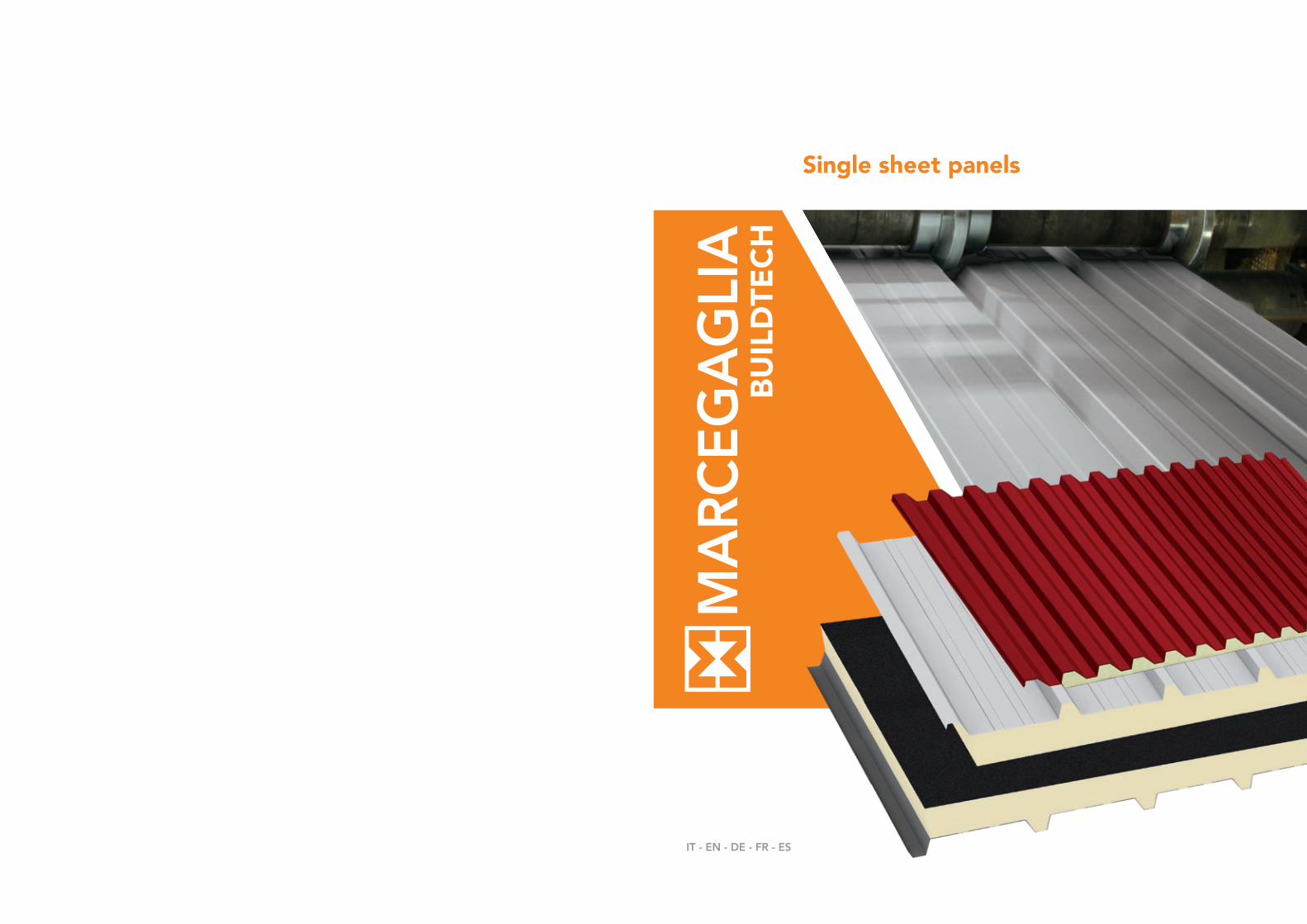
Single sheet panels
IT - EN - DE - FR - ES
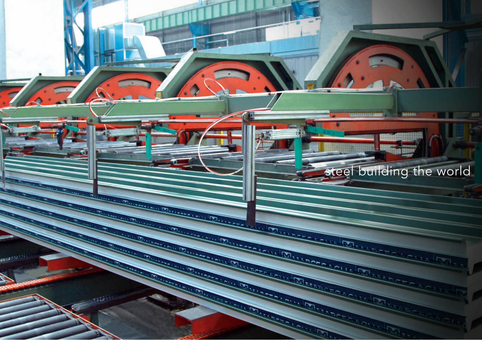
54 Marcegaglia Buildtech Marcegaglia Buildtech 55
steel building the world

56 Marcegaglia Buildtech Marcegaglia Buildtech 57
Marcegaglia è un gruppo industriale leader mondiale nella tra-sformazione dell’acciaio, con 5,6 milioni di tonnellate lavorate ogni anno. Dalla prima trasformazione, nell’ambito della propria filiera produttiva controllata, Marcegaglia ricava la gamma più ampia al mondo di semilavorati e prodotti finiti in acciaio.
Marcegaglia is the leading industrial group worldwide in the steel process-ing sector, with a yearly output of 5.6 million tons. After first transforma-tion, within its controlled value chain Marcegaglia develops the world’s widest range of steel semi-products and finished goods.
Marcegaglia ist der weltweit führende Industriekonzern im Bereich Stahlum-wandlung mit jährlich 5,6 Millionen Tonnen verarbeitetem Stahl. Aus der ersten Umwandlung innerhalb der eigenen, kontrollierten Produktionskette erzeugt Marcegaglia das weltweit umfangreichste Sortiment an Halb- und Fertigerzeugnissen.
Marcegaglia est le groupe industriel leader mondial de la transformation de l’acier avec 5,6 millions de tonnes usinées chaque année. De la première trans-formation, dans sa propre filière de production contrôlée, Marcegaglia obtient la gamme de produits semi-ouvrés et de produits finis en acier la plus étendue du monde.
Marcegaglia es el grupo industrial líder mundial en la transformación del acero, con 5,6 millones de toneladas trabajadas cada año. Desde la primera transformación en el ámbito de su hilera productiva controlada, Marcegaglia obtiene la gama de semiproductos y productos acabados en acero más amplia a escala mundial.
Pannelli coibentati monolamieraSingle sheet insulated panelsIsolierpaneele aus einschichtigem BlechPanneaux sandwich avec tôle sur une facePanels aislantes mono-chapa
La gamma di pannelli coibentati monolamiera Marcegaglia Bu-ildtech per parete e copertura è parte della filiera produttiva cer-tificata di semilavorati e prodotti finiti in acciaio per applicazione nel settore dell’edilizia civile e industriale oltre che, nella versione dedicata con vertroresina PRFV, per applicazioni nel settore agro-zootecnico.
La produzione è interamente realizzata nel più grande e moderno stabilimento italiano specializzato di Pozzolo Formigaro (Nord Italia), recentemente ampliato e rinnovato con le ultime tecnolo-gie produttive per garantire qualità e innovazione di prodotto, e nello stabilimento di Praszka (Polonia).
The Marcegaglia Buildtech range of single-sheet insulated wall and roofing panels forms part of the certified production chain of unfinished and finished steel products for application in the civil and industrial construction sector, as well as agricultural and zootechnical applications in the special PRFV fi-breglass version.
They are entirely manufactured in Italy’s largest, most modern specialist plant at Pozzolo Formigaro (northern Italy), recently expanded and renewed with the latest production technologies to guarantee product quality and innova-tion, and at the Praszka (Poland) plant.
Das Sortiment von Marcegaglia Buildtech an Isolierpaneelen aus ein-schichtigem Blech für Wände und Abdeckungen ist Teil der zertifizier-ten Produktionskette von halbfertigen und fertigen Stahlerzeugnissen zur Anwendung im Zivil- und Industriebauwesen; außerdem findet es in der zweckbestimmten Version aus Glasfaser (PRFV) im Bereich Landwirtschaft und Viehzucht Anwendung.
Die komplette Fertigung erfolgt im größten und modernsten italienischen Spezialwerk in Pozzolo Formigaro (Norditalien), das erst kürzlich erweitert und mit den neuesten Herstellungstechnologien ausgestattet wurde, um Qua-lität und Produktinnovation zu gewährleisten, sowie in dem Werk in Praszka (Polen).
La gamme de panneaux de bardage à une face Marcegaglia Buildtech pour mur et couverture fait partie de la filière de production certifiée de produits semi-finis et finis en acier pour une application dans le secteur des construc-tions civiles et industrielles, ainsi que, pour la version dédiée avec vitrorésine PRFV, pour des applications dans le secteur agro-zootechnique.
La production est entièrement réalisée dans le plus grand établissement ita-lien moderne spécialisé de Pozzolo Formigaro (nord de l’Italie), agrandi dernièrement et rénové selon les dernières technologies productives afin de garantir la qualité et l’innovation du produit, ainsi que dans l’établissement de Praszka (Pologne).
La gama de paneles aislantes mono-chapa Marcegaglia Buildtech para pa-redes y cubiertas forma parte de la cadena de producción certificada de pro-ductos semiacabados y acabados de acero para aplicaciones en el sector de la construcción civil e industrial así como, en la versión dedicada con fibra de vidrio PRFV, para aplicaciones en el sector agrozootécnico.
La producción se realiza íntegramente en la planta especializada italiana más grande y moderna de Pozzolo Formigaro (al norte de Italia), recientemente ampliada y renovada con las últimas tecnologías de producción para garan-tizar la calidad e innovación del producto, así como en la planta de Praszka (Polonia).

58 Marcegaglia Buildtech Marcegaglia Buildtech 59
SUPPORTIMetallic supportsSchalenSupportsSoportes
Acciaio zincato Sendzimir secondo EN 10143 ed EN 10346 con qualità S250GD
Preverniciati secondo EN 10169 (Coil Coating) in base alle norme ECCA ed EURONORME:
di produzione normale: - con rivestimento MP3 poliesteri
di produzione speciale: - con rivestimento MP5 poliesteri modificati/ poliuretanici- con rivestimento MP10 fluorocarbonici- con rivestimento MP20 poliuretanici/ poliammidici- con rivestimento MPHR
Acciaio zincato plastificato EN 10346
Alluminio naturale, preverniciato EN 485-2, EN 573-3, EN 11396
Rame, inox e secondo le necessità EN 1172, EN 1173, EN 1412
Sendzimir galvanised steel compliant with EN 10143 and EN 10346, S250GD grade
Pre-painted steel according to EN 10169 (coil coating) and to ECCA norms and EURONORMS:
standard production: - with MP3 polyester coating
special production: - with MP5 modified polyester/polyurethane coating - with MP10 fluorocarbon coating - with MP20 polyurethane/polyamide coating- with MPHR coating
Plastic coated, galvanized steel EN 10346
Natural, pre-painted aluminium EN 485-2, EN 573-3, EN 11396
Copper, stainless steel or other materials upon request EN 1172, EN 1173, EN 1412
Sendzimir-verzinkter Stahl gemäß EN 10143 und EN 10346 in der Güte S250GD
Beschichteter Stahl gemäß EN 10169 (coil coating ) und nach ECCA Richtlinien und EURONORMEN:
normale Fertigung: - mit Polyesterbeschichtung (MP3)
Sonderfertigung: - mit geänderter Polyurethan-/ Polyesterbeschichtung (MP5)- mit mit Fluorocarbon- beschichtung (MP10)- mit Polyurethan-/ Polyamidbeschichtung (MP20)- mit MPHR-Beschichtung
Kunststoff beschichteter verzinkter Stahl nach EN 10346
Unbehandelter, vorgestrichener Aluminium nach EN 485, EN 573, EN 11396
Kupfer, Edelstahl je nach Anfrage gemäß EN 1172, EN 1173 und EN 1412
Acier galvanisé Sendzimir selon EN 10143 et EN 10346, avec qualité S250GD
Pré-vernis selon EN 10169 (Coil Coating) en fonction des normes ECCA et EURONORME:
de production normale: - avec revêtement MP3 en polyester
de production spéciale: - avec revêtement MPS en polyester modifié/ polyuréthane- avec revêtement MP10 en fluorocarbone- avec revêtement MP20 en polyuréthane/ polyamide- avec revêtement MPHR
Acier galvanisé plastifié EN 10346
Aluminium naturel, pré -vernis EN 485-2, EN 573-3, EN 11396
Cuivre, inox, et selon les besoins EN 1172, EN1173, EN 1412
Acero galvanizado Sendzimir según EN 10143 y EN 10346, con calidad S250GD
Prelacados según EN 10169 (Coil Coating) de acuerdo con las normas ECCA y EURONORME:
de producción normal: - con revestimiento MP3 poliésteres
de producción especial: - con revestimiento MP5 poliésteres modificados/ poliuretánicos- con revestimiento MP10 fluorocarbónicos- con revestimiento MP20 poliuretánicos/ poliamídicos- con revestimiento MPHR
Acero galvanizado plastificado EN 10346
Aluminio natural, prelacado EN 485-2, EN 573-3, EN 11396
Cobre, inox y según las necesidades EN 1172, EN 1173, EN 1412
COIBENTAZIONEInsulationIsolierungIsolantAislamiento térmico
Sono utilizzate formulazioni poliuretaniche esenti da CFC e HCFC che producono schiume isolanti anigroscopiche, antimuffa e ad alto contenuto di celle chiuse (>95%). Per le richieste di prestazione al fuoco, possono essere impiegate schiume con reazione al fuoco particolarmente performanti.
Conducibilità termica λ: 0,021 W/mK
Densità media totale: 35 - 40 kg/m3
We use CFC and HCFC FREE, polyurethane products that are capable of producing waterproof, mold-resistant insulating foams with a high percentage of closed cells (>95%). High-performance reactive fire resistant foams are available when greater fire resistance is required.
Thermic conductivity λ: 0,021 W/mK
Overall average density: 35 - 40 kg/m3
Es werden FCKW- und HCFC-freie Polyurethan-produkte verwendet, die einen isolierenden, nicht hygroskopischen Schaum bilden, dem Schimmel entgegen wirken und einen hohen Gehalt an geschlossenen Zellen bewahren (>95%). Was die Feuerleistungs-anforderungen angeht, kann Schaum mit beson-ders hoher Feuerfestig-keit benutzt werden.
Wärmeleitfähigkeit λ: 0,021 W/mK
mittlere Dichte:35 - 40 kg/m3
Formules utilisées à base de polyuréthane sans CFC ni HCFC produisant des mousses isolantes anigroscopiques, anti-moisissures et comportant plus de 95 % de cellules fermées. Des mousses offrant une réaction au feu particulièrement performante peuvent également être utilisées.
Conductibilité thermiqueλ: 0,021 W/mK
Densité moyenne totale:35 - 40 kg/m3
Se utilizan productos poliuretánicos libres de CFC y HCFC que producen espumas aislantes anhigroscópicas, antimoho y con elevado contenido de celdas cerradas (>95%). Para prestaciones contra el fuego, pueden utilizarse espumas con reacción al fuego particularmente válidas.
Conductibilidad térmicaλ: 0,021 W/mK
Densidad media total:35 - 40 kg/m3
Le lane di roccia impiegate sono di tipo biosolubile, anigroscopico, inimputrescibili e incombustibili (classe A1 europea di reazione al fuoco)
Conducibilità termica λ: 0,043 W/mK (correttamente misurata nella direzione delle fibre)
Densità media totale: 95 - 105 kg/m3
We use mineral wool that is biosoluble, waterproof, rot proof, and fire resistant (European Fire Resistance Rating A1)
Thermic conductivity λ: 0,043 W/mK(correctly measured in the fiber direction)
Overall average density: 95 - 105 kg/m3
Die verwendete Mineralwolle ist biologisch abbaubar, nicht hygroskopisch, praktisch unverrottbar und nicht brennbar (Europäische Klasse A1 in Bezug auf das Brandverhalten)
Wärmeleitfähigkeitλ: 0,043 W/mK(Korrekt in Faserrichtung gemessen)
Mittlere Dichte:95 - 105 kg/m3
Les laines de roche utilisées sont biosolubles, anigroscopiques, imputrescibles et incombustibles (classe A1 européenne de réaction au feu)
Conductibilité thermiqueλ: 0,043 W/mK(correctement mesurée dans le sens des fibres)
Densité moyenne totale:95 - 105 kg/m3
Las lanas de roca utilizadas son de tipo biosoluble, anhigroscópico, imputrescibles e incombustibles (clase A1 europea de reacción al fuego)
Conductibilidad térmicaλ: 0,043 W/mK(correctamente medida en la dirección de las fibras)
Densidad media total:95 - 105 kg/m3
Sia per il poliuretano che per la lanadi roccia, nelle schede prodotto sono indicate le trasmittanze termiche U calcolate secondo la norma EN ISO 6946. Per i soli pannelli soggetti a marcatura CE, sono indicate anche le trasmittanze termiche calcolate secondo la norma prodotto EN 14509.
The product data sheets for both the polyurethane and mineral wool indicate the heat transmittance, U, calculated according to EN ISO 6946. Data sheets for CE marked panels only also indicate the thermal transmittance calculated according to the product standard EN 14509.
In den Datenblättern sind sowohl für das Polyurethan als auch für die Mineralwolle die gemäß EN ISO 6946 berechneten Wärmedurchgangswerte (U-Werte) angegeben. Für die der CE-Kennzeichnung unterliegenden Paneele dagegen sind auch die gemäß EN 14509 berechneten Wärmedurchgangswerte angegeben.
Les transmittances thermiques U calculées selon la norme EN ISO 6946 sont indiquées sur les fiches produit du polyuréthane et de la laine de roche. Les transmittances thermiques calculées selon la norme EN 14509 sont également indiquées pour les panneaux soumis au label CE.
Tanto para el poliuretano como para la lana de roca, en las fichas del producto se indican las transmitancias térmicas U calculadas conforme a EN ISO 6946.Solo para los paneles sujetos a marcado CE, también se indican las transmitancias térmicas calculadas conforme a la norma producto EN 14509.
ADERENZAAdhesionAnhaftungAdhérenceAdherencia
Vengono usualmente considerate nella norma zone di non aderenza con dimensioni non superiori a 5% della superficie del pannello.Aderenza tra i supporti 0,10 N/mm2.
Non-adhesion zones are usually considered as normal with dimensions not exceeding 5% of the panel surface.Adherence between supports 0,10 N/mm2.
Gewöhnlich gelten die solche Bereiche als innerhalb der Norm, deren Nichthaftung Abmessungen von nicht mehr als 5% der Baulement-Oberfläche beträgt.Haftfestigkeit zwischen Trägern 0,10 N/mm2.
Des zones de non-adhérence, inférieures à 5% de la surface du panneau sont considérées comme conformes à la norme.Adhérence entre les supports 0,10 N/mm2.
Se consideran conformes con la norma aquellas zonas de “no adherencia” con dimensiones no superiores al 5% de la superficie del panel. Adherencia entre los soportes 0,10 N/mm2.
top a finirefinishing top coat
trattamento chimicochemical treatment
trattamento chimico chemical treatment
zincatura a caldohot dip galvanization
acciao laminato a freddo S250GD S250GD cold rolled steel
primer o back coatprimer or back coat
primerprimer
zincatura a caldohot dip galvanization
Specifiche tecniche - Pannelli coibentatiTechnical specifications - Insulated panels Spezifikationen - BauelementeSpécifications techniques - Panneaux isolantsEspecificaciones técnicas - Paneles aislantes
ACCIAIO AL CARBONIO PREVERNICIATO sec. EN 10169
PRE-PAINTED CARBON STEEL according to EN 10169

60 Marcegaglia Buildtech Marcegaglia Buildtech 61
TOLLERANZE DIMENSIONALITolerances on dimensionsAbmessungstoleranzenTolérances dimensionnellesTolerancias dimensionales
Spessore pannello± 3 mm
Altezza greche ± 1 mm max
Passo tra le greche ± 2 mm
Lunghezza pannello± 10 mm
Fuori squadra ≤ 0,5% larghezza utile
Sciabolatura≤ 2 mm per metro
Centinatura ≤ 1% della lungh./largh.
Ondulazione dei bordi ± 2 mm su 500 mm
Disallineamento supporti ≤ 3 mm
Larghezza utile ± 5 mm
Panel thickness± 3 mm
Corrugation height± 1 mm max
Pitch between corrugations ± 2 mm
Panel length ± 10 mm
Out of square≤ 0,5% useful width
Longitudinal bowing≤ 2 mm per metre
Camber≤ 1% of the length/width
Edges undulation± 2 mm over 500 mm
Support misalignment≤ 3 mm
Net width± 5 mm
Stärke des Paneels± 3 mm
Sickenhöhe± 1 mm max
Abstand zwischen den Riffeln ± 2 mm
Baulement-Länge± 10 mm
Abw. v. Rechtwinkligkeit≤ 0,5% Nutzbreite
Gradheit≤ 2 mm pro Meter
Welligkeit≤ 1% der Breite/Länge
Kräuselung an den Rändern± 2 mm su 500 mm
Nichtfluchtung Schalen≤ 3 mm
Nutzbreite ± 5 mm
Épaisseur du panneau± 3 mm
Hauteur des ondes± 1 mm max
Pas entre les ondes ± 2 mm
Longueur du panneau± 10 mm
Défaut d’équerrage≤ 0,5% largeur utile
Courbure≤ 2 mm par mètre
Cintrage≤ 1% de la longueur/largeur
Ondulation aux bords± 2 mm sur 500 mm
Désalignement supports ≤ 3 mm
Largeur utile ± 5 mm
Espesor panel± 3 mm
Altura grecas ± 1 mm max
Paso entre grecas ± 2 mm
Longitud panel ± 10 mm
Descuadre ≤ 0,5% ancho útil
Flecha ≤ 2 mm por metro
Cimbreado ≤ 1% de la longitud/ancho
Ondulación en los bordes ± 2 mm su 500 mm
Desalineación soportes ≤ 3 mm
Ancho útil ± 5 mm
PLANARITÀFlatnessEbenheitPlanéritéPlanaridad
Lievi ondulazioni in particolare con rivestimenti sottili ed in particolare con rivestimenti in alluminio non sono considerate anomalie con scostamenti max di 3 mm su passi max di 1000 mm.
Slight undulations, in particular with thin coatings and aluminium coatings are not considered as anomalies with a maximum deviation of 3 mm on max. pitches of 1000 mm.
Leichte Welligkeit insbesondere bei Aluminium-verkleidungen werden bei Abweichungen von max. 3 mm auf max Abständen von 1000 mm nicht als Fehler betrachtet.
De légères ondulations, notamment avec des parements fins et en aluminium, ne sont pas considérées comme anomalies jusqu’à des écarts de 3 mm maxi sur un pas de 1000 mm maxi.
Leves ondulaciones (con alejamientos máxi-mos de 3 mm. en pasos máximos de 1000 mm.) en particular en caso de recubrimientos finos y en particular de aluminio, no se consideran anomalías.
FINITUREFinishVerarbeitungFinitionsAcabados
Vengono considerate nella norma leggere fuoriuscite di schiuma dai giunti ed eventuali lievi mancanze od irregolarità nella posizione delle guarnizioni, sempre che ciò non pregiudichi la funzionalità del pannello.
Slight leaking of foam from the joints and slight omissions or irregularities in the position of the gasket are considere acceptable, as long as the functional character of the panel is not compromised.
Geringes Austreten von Schaum aus den Fugen und eventuelle leichte Mängel oder Unregel-mäßigkeiten der Position der Dichtungen gelten als im Rahmen der Norm, jedoch stets unter der Voraussetzung, dass die Funktionsfähigkeit der Platte hiervon nicht beeinträchtigt wird.
De légères fuites de mousse aux joints ou d’éventuels légers défauts ou irrégularités dans la position des joints sont considérés comme admissibles, dans la mesure où la fonctionnalité du panneau n’est pas compromise.
Ligeras pérdidas de espuma en las uniones y eventuales faltas o irregularidades en la posición de las juntas, se consideran conformes con la norma, siempre y cuando non perjudiquen el buen funcionamiento del panel.
FISSAGGIOFixingBefestigungFixationFijación
Normalmente eseguito con viti tipo BS 6.3 in corrispondenza delle nervature principali e cappellotto con guarnizione incorporata più rondella, e comunque in maniera non difforme da quanto specificato dal progetto. Il progettista in fase di esecuzione dovrà tenere in considerazione la direzione dei venti dominanti per determinare il senso di montaggio dei pannelli, dovrà inoltre considerare altitudine, carichi e sovraccarichi per determinare il numero dei fissaggi.
In caso di coperture con luci libere importanti, si raccomanda l’applicazione di una cucitura del giunto longitudinale con interasse viti non superiore al metro.
Normally mounted using BS 6.3 type screws through the main ribbing, or in all cases in accordance with the project specifications. For roofs panels a cap nuts with an incorporated gasket and a washer are employed, everything in compliance with the design specification. When performing the design work, the designer must evaluate the direction of the local winds in order to determine the panel mounting directions and should also consider altitude, loads and overloads when calculating the number of fixing elements.
For roofs with large unsupported spaces, we recommend applying a jointing rib with a center distance between the screws no greater than 1 m.
Normale Ausführung mit Schrauben vom Typ BS 6.3 in Höhe der Hauptrippen, in jedem Fall entsprechend der spezifischen Angaben des jeweiligen Projekts. Bei der Ausführung hat der Konstrukteur zur Bestimmung der Montagerichtung der Paneele die vorherrschende Windrichtung, außerdem die Höhe sowie die Belastungen und Überbelastungen zu berücksichtigen, um die Anzahl der Halterungen festzulegen.
Bei Verkleidungen mit sehr großer lichter Weite empfiehlt sich das Verschrauben der Stossfuge in Längsrichtung, wobei der Abstand zwischen den Schrauben nicht größer als ein Meter sein sollte.
Normalement monté avec des vis de type BS 6.3 à appliquer sur les nervures principales, conformément aux indications fournies dans le projet. Lors de l’exécution, le chef de projet devra tenir compte de la direction des vents dominants pour déterminer le sens de montage des panneaux. En outre, il devra prendre en considération l’altitude, les charges et surcharges pour calculer le nombre de fixations.
En cas de couvertures avec des espaces libres importants, une couture longitudinale du joint avec une distance entre les vis d'1 m max. est conseillée.
La fijación se realiza normalmente mediante tornillos tipo BS 6.3 en correspondencia con los nervios principales y siempre de forma no discordante con lo especificado en el proyecto. Durante la fase de ejecución, el proyectista deberá tener en cuenta la dirección de los vientos dominantes para determinar el sentido de montaje de los paneles; además tendrá que considerar la altitud, las cargas y las sobrecargas para poder establecer el número de fijaciones.
En caso de coberturas con aberturas importantes,se recomienda aplicar una costura de la junta longitudinal con distancia entre tornillos no superior a 1 metro.
PORTATECapacitiesTragfähigkeitChargesCargas
I valori indicati nelle tabelle di portata sono il risultato di prove pratiche eseguite presso i nostri laboratori ed istituti certificatori ed è comunque di competenza del progettista la verifica degli stessi in funzione dell’applicazione.
The figures reported in the table are the results of the tests carried out both by our laboratories and by certified third bodies.The designer is responsible for checking the applicability of the data based on the specific project requirements.
Die in den Tabellen angegebenen Werte stellen das Ergebnis praktischer Versuche in unseren eigenen Labors wie auch bei zertifizierten Instituten dar. Die Überprüfung dieser Werte in Bezug auf die jeweilige Anwendung obliegt jedoch auf jeden Fall dem Planer.
Les valeurs indiquées dans les tableaux de portée sont le résultat d'essais pratiques effectués dans nos laboratoires et instituts de certification. L'auteur du projet doit néanmoins les vérifier en fonction de l'application.
Los valores indicados en las tablas de carga útil son el resultado de pruebas prácticas realizadas en nuestros laboratorios e institutos de certificación; en todo caso, es competencia del autor del proyecto comprobarlos en función de su aplicación.

53 mm 25 mm250 mm
1000 mm
40 mm
Il montaggio dei pannelli in parete può avvenire in posa sia verticale sia orizzontale. Nel caso di posa orizzontale si raccomanda di posizionare i pannelli con il maschio verso l’alto. Panels may be mounted as wall cladding, both vertically and horizontally. When mounting horizontally, it is recommended to install the panels with male facing up.
Pannelli coibentati metallici con supporto esterno in acciaio zincato Sendzimir, alluminio, rame, acciaio inox ecc. e uno strato interno in alluminio centesimale naturale, con pendenze >7%.Particolarmente indicati per la fabbricazione di coperture leggere dove è comunque importante l'isolamento termico.
Insulated metal panels with exterior support in Sendzimir galvanized steel, aluminum, copper, stainless steel etc., and an interior layer of plain aluminum foil. Highly suitable for constructing light roofs where thermal insulation plays an important role, with pitches of >7%.
Metallische Isolierungspaneele mit Außenträger aus sendzimirverzinktem Stahl, Aluminium, Kupfer, Edelstahl usw. und einer Innenschicht aus weißem Aluminium-Feinblech. Besonders geeignet für die Herstellung von leichten Verkleidungen, bei denen jedoch die Wärmeisolierung besonders wichtig ist, mit Neigungen >7%.
Panneaux isolants métalliques avec support externe en acier galvanisé Send-mizir, aluminium, cuivre, acier inox etc. et couche interne en aluminium cen-tésimal naturel. Particulièrement indiqués pour la fabrication de couvertures légères où l’isolation thermique est importante, avec des pentes >7%.
Paneles aislados metálicos con soporte exterior de acero galvanizado Sendzi-mir, aluminio, cobre, acero inoxidable, etc. y una capa interior de aluminio centesimal natural. Particularmente indicados para la fabricación de cober-turas ligeras donde en todo caso es importante el aislamiento térmico, con pendientes >7%.
Pannelli copertura monolamieraSingle sheet roofing panelsVerkleidungspaneele mit einseitigem DeckblechPanneaux couverture tôle simple Paneles de cobertura chapa única
TK5 AC
CARATTERISTICHECharacteristicsEigenschaftenCaractéristiquesCaracterísticas
FrecciaF≤ 1/200 L
NoteÈ possibile anche il montaggio rovesciato
DeflectionF≤ 1/200L
NotesCan also be installed upside-down
DurchbiegungF≤ 1/200L
BemerkungenAuch die umgekehrte Montage ist möglich
FlècheF≤ 1/200L
NotesMontage à l’envers possible
FlechaF≤ 1/200L
NotasTambién es posible el montaje al revés
TK5
AC
TK5 AC ACCIAIO - STEEL
Spessore supporto
Support thickness
Distanza fra gli appoggi in m - Supports spacing (m)
campata semplice - simple span
mm 1 1,25 1,5 1,75 2 2,25 2,5 2,75 3 3,25 3,5 3,75
Carico massimo uniformemente distribuito in kN/m2 acciaio - Max load capacity kN/m2 steel
0,5 5,10 3,32 2,31 1,69 1,30 0,96 0,71
0,6 6,14 3,93 2,73 2,00 1,53 1,15 0,84 0,63 0,48 0,38
0,7 7,16 4,58 3,18 2,34 1,79 1,35 0,98 0,73 0,57 0,44 0,35
0,8 8,20 5,24 3,64 2,67 2,05 1,54 1,12 0,84 0,65 0,51 0,41 0,33
1,0 10,24 6,55 4,55 3,34 2,56 1,93 1,40 1,05 0,81 0,64 0,51 0,41
TK5 AC ACCIAIO - STEEL
Spessore supporto
Support thickness
Distanza fra gli appoggi in m - Supports spacing (m)
campata multipla - multiple span
mm 1 1,25 1,5 1,75 2 2,25 2,5 2,75 3 3,25 3,5 3,75
Carico massimo uniformemente distribuito in kN/m2 acciaio - Max load capacity kN/m2 steel
0,5 6,64 4,30 2,88 2,12 1,63 1,30 1,05 0,86 0,69 0,54
0,6 7,68 4,91 3,41 2,51 1,92 1,52 1,23 1,01 0,81 0,64 0,51
0,7 9,46 6,12 4,27 3,13 2,39 1,81 1,43 1,18 0,95 0,74 0,59 0,48
0,8 11,04 7,04 4,87 3,56 2,71 2,13 1,64 1,35 1,08 0,85 0,68 0,55
1,0 14,13 9,16 6,33 4,63 3,52 2,77 2,04 1,69 1,35 1,06 0,85 0,69
TK5 AC ALLUMINIO - ALUMINIUM
Spessore supporto
Support thickness
Distanza fra gli appoggi in m - Supports spacing (m)
campata semplice - simple span campata multipla - multiple span
mm 1 1,25 1,5 1,75 2 2,25 2,50 1 1,25 1,5 1,75 2 2,25 2,50
Carico massimo uniformemente distribuito in kN/m2 alluminio - Max load capacity kN/m2 aluminium
0,6 2,97 1,90 1,28 0,80 0,54 0,38 0,28 3,71 2,37 1,65 1,21 0,90 0,60 0,45
0,7 3,46 2,21 1,49 0,94 0,63 0,44 0,32 4,33 2,77 1,92 1,41 1,05 0,74 0,54
0,8 3,96 2,53 1,70 1,07 0,72 0,51 0,37 4,95 3,16 2,20 1,62 1,20 0,84 0,61
1,0 4,94 3,16 2,13 1,34 0,90 0,63 0,46 6,18 3,96 2,75 2,02 1,50 1,05 0,77
Alluminio centesimaleEmbossed alluminum
CoibentazioneInsulation
Nastro adesivoAdhesive tape
Supporto metallicoMetallic support
Trasmittanza termica - Thermal transmittance
Spessore pannello Panel thickness
U
mm W/m2K
EN ISO 6946
20 0,72
30 0,53
40 0,42
50 0,35
60 0,30
80 0,23
100 0,19
Peso nominale dei pannelli - Nominal panel weight / kg/m2
Spessore nominale lamiera Nominal metal sheet thickness
Spessore nominale pannello mm - Nominal panel thickness mm
mm 20 30 40 50 60 80 100
Acciaio Steel
0,5 6,1 6,5 6,9 7,3 7,6 8,4 9,2
0,6 7,1 7,5 7,9 8,2 8,6 9,4 10,1
0,7 8,1 8,5 8,8 9,2 9,6 10,4 11,1
0,8 9,1 9,5 9,8 10,2 10,6 11,4 12,1
1,0 11,0 11,4 11,8 12,2 12,6 13,3 14,1
Alluminio Aluminium
0,6 3,2 3,6 4,0 4,4 4,8 5,5 6,3
0,7 3,6 4,0 4,3 4,7 5,1 5,9 6,6
0,8 3,9 4,3 4,7 5,1 5,4 6,2 7,0
1,0 4,6 5,0 5,3 5,7 6,1 6,9 7,6
62 Marcegaglia Buildtech Marcegaglia Buildtech 63
Resistenza al fuoco dall’esterno - External fire performance
supporto esternoexternal support
Broof (t2)
acciaio - steel certificato - certified
alluminio - aluminium certificato - certified
Broof (t2)
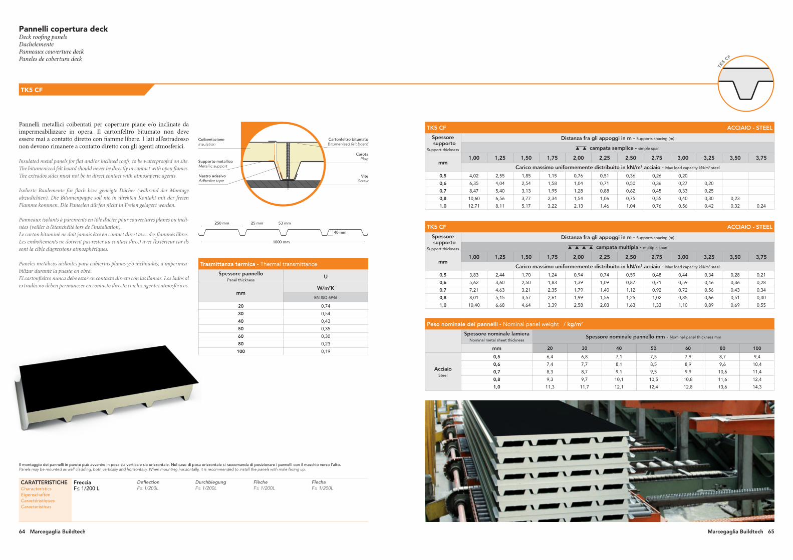
Il montaggio dei pannelli in parete può avvenire in posa sia verticale sia orizzontale. Nel caso di posa orizzontale si raccomanda di posizionare i pannelli con il maschio verso l’alto. Panels may be mounted as wall cladding, both vertically and horizontally. When mounting horizontally, it is recommended to install the panels with male facing up.
Peso nominale dei pannelli - Nominal panel weight / kg/m2
Spessore nominale lamiera Nominal metal sheet thickness
Spessore nominale pannello mm - Nominal panel thickness mm
mm 20 30 40 50 60 80 100
Acciaio Steel
0,5 6,4 6,8 7,1 7,5 7,9 8,7 9,4
0,6 7,4 7,7 8,1 8,5 8,9 9,6 10,4
0,7 8,3 8,7 9,1 9,5 9,9 10,6 11,4
0,8 9,3 9,7 10,1 10,5 10,8 11,6 12,4
1,0 11,3 11,7 12,1 12,4 12,8 13,6 14,3
Trasmittanza termica - Thermal transmittance
Spessore pannello Panel thickness
U
mm W/m2K
EN ISO 6946
20 0,74
30 0,54
40 0,43
50 0,35
60 0,30
80 0,23
100 0,19
Pannelli metallici coibentati per coperture piane e/o inclinate da impermeabilizzare in opera. Il cartonfeltro bitumato non deve essere mai a contatto diretto con fiamme libere. I lati all’estradosso non devono rimanere a contatto diretto con gli agenti atmosferici.
Insulated metal panels for flat and/or inclined roofs, to be waterproofed on site. The bitumenized felt board should never be directly in contact with open flames.The extrados sides must not be in direct contact with atmoshperic agents.
Isolierte Baulemente für flach bzw. geneigte Dächer (während der Montage abzudichten). Die Bitumenpappe soll nie in direkten Kontakt mit der freien Flamme kommen. Die Paneelen dürfen nicht in Freien gelagert werden.
Panneaux isolants à parements en tôle d’acier pour couvertures planes ou incli-nées (veiller à l’étanchéité lors de l’installation). Le carton bituminé ne doit jamais être en contact direst avec des flammes libres. Les emboîtements ne doivent pas rester au contact direct avec l’extérieur car ils sont la cible d’agressions atmosphériques.
Paneles metálicos aislantes para cubiertas planas y/o inclinadas, a impermea-bilizar durante la puesta en obra. El cartonfieltro nunca debe estar en contacto directo con las llamas. Los lados al extradós no deben permanecer en contacto directo con los agentes atmosféricos.
Pannelli copertura deck Deck roofing panelsDachelementePanneaux couverture deckPaneles de cobertura deck
TK5 CF
CARATTERISTICHECharacteristicsEigenschaftenCaractéristiquesCaracterísticas
FrecciaF≤ 1/200 L
DeflectionF≤ 1/200L
DurchbiegungF≤ 1/200L
FlècheF≤ 1/200L
FlechaF≤ 1/200L
Cartonfeltro bitumatoBitumenized felt board
CoibentazioneInsulation
Nastro adesivoAdhesive tape
CarotaPlug
ViteScrew
Supporto metallicoMetallic support
TK5
CF
53 mm25 mm250 mm
1000 mm
40 mm
TK5 CF ACCIAIO - STEEL
Spessore supporto
Support thickness
Distanza fra gli appoggi in m - Supports spacing (m)
campata semplice - simple span
mm 1,00 1,25 1,50 1,75 2,00 2,25 2,50 2,75 3,00 3,25 3,50 3,75
Carico massimo uniformemente distribuito in kN/m2 acciaio - Max load capacity kN/m2 steel
0,5 4,02 2,55 1,85 1,15 0,76 0,51 0,36 0,26 0,20
0,6 6,35 4,04 2,54 1,58 1,04 0,71 0,50 0,36 0,27 0,20
0,7 8,47 5,40 3,13 1,95 1,28 0,88 0,62 0,45 0,33 0,25
0,8 10,60 6,56 3,77 2,34 1,54 1,06 0,75 0,55 0,40 0,30 0,23
1,0 12,71 8,11 5,17 3,22 2,13 1,46 1,04 0,76 0,56 0,42 0,32 0,24
TK5 CF ACCIAIO - STEEL
Spessore supporto
Support thickness
Distanza fra gli appoggi in m - Supports spacing (m)
campata multipla - multiple span
mm 1,00 1,25 1,50 1,75 2,00 2,25 2,50 2,75 3,00 3,25 3,50 3,75
Carico massimo uniformemente distribuito in kN/m2 acciaio - Max load capacity kN/m2 steel
0,5 3,83 2,44 1,70 1,24 0,94 0,74 0,59 0,48 0,44 0,34 0,28 0,21
0,6 5,62 3,60 2,50 1,83 1,39 1,09 0,87 0,71 0,59 0,46 0,36 0,28
0,7 7,21 4,63 3,21 2,35 1,79 1,40 1,12 0,92 0,72 0,56 0,43 0,34
0,8 8,01 5,15 3,57 2,61 1,99 1,56 1,25 1,02 0,85 0,66 0,51 0,40
1,0 10,40 6,68 4,64 3,39 2,58 2,03 1,63 1,33 1,10 0,89 0,69 0,55
64 Marcegaglia Buildtech Marcegaglia Buildtech 65

TK5
CF PL
Peso nominale dei pannelli - Nominal panel weight / kg/m2
Spessore nominale lamiera Nominal metal sheet thickness
Spessore nominale pannello mm - Nominal panel thickness mm
mm 20 30 40 50 60 80 100
Acciaio Steel
0,5 6,4 6,8 7,1 7,5 7,9 8,7 9,4
0,6 7,4 7,7 8,1 8,5 8,9 9,6 10,4
0,7 8,3 8,7 9,1 9,5 9,9 10,6 11,4
0,8 9,3 9,7 10,1 10,5 10,8 11,6 12,4
1,0 11,3 11,7 12,1 12,4 12,8 13,6 14,3
TK5 CF PL ACCIAIO - STEEL
Spessore supporto
Support thickness
Distanza fra gli appoggi in m - Supports spacing (m)
campata semplice - simple span
mm 1,00 1,25 1,50 1,75 2,00 2,25 2,50 2,75 3,00 3,25 3,50 3,75
Carico massimo uniformemente distribuito in kN/m2 acciaio - Max load capacity kN/m2 steel
0,5 4,02 2,55 1,85 1,15 0,76 0,51 0,36 0,26 0,20
0,6 6,35 4,04 2,54 1,58 1,04 0,71 0,50 0,36 0,27 0,20
0,7 8,47 5,40 3,13 1,95 1,28 0,88 0,62 0,45 0,33 0,25
0,8 10,60 6,56 3,77 2,34 1,54 1,06 0,75 0,55 0,40 0,30 0,23
1,0 12,71 8,11 5,17 3,22 2,13 1,46 1,04 0,76 0,56 0,42 0,32 0,24
TK5 CF PL ACCIAIO - STEEL
Spessore supporto
Support thickness
Distanza fra gli appoggi in m - Supports spacing (m)
campata multipla - multiple span
mm 1,00 1,25 1,50 1,75 2,00 2,25 2,50 2,75 3,00 3,25 3,50 3,75
Carico massimo uniformemente distribuito in kN/m2 acciaio - Max load capacity kN/m2 steel
0,5 3,83 2,44 1,70 1,24 0,94 0,74 0,59 0,48 0,44 0,34 0,28 0,21
0,6 5,62 3,60 2,50 1,83 1,39 1,09 0,87 0,71 0,59 0,46 0,36 0,28
0,7 7,21 4,63 3,21 2,35 1,79 1,40 1,12 0,92 0,72 0,56 0,43 0,34
0,8 8,01 5,15 3,57 2,61 1,99 1,56 1,25 1,02 0,85 0,66 0,51 0,40
1,0 10,40 6,68 4,64 3,39 2,58 2,03 1,63 1,33 1,10 0,89 0,69 0,55
TK5 CF PL
Pannelli copertura deck Deck roofing panelsDachelementePanneaux couverture deckPaneles de cobertura deck
Pannelli metallici coibentati per coperture piane e/o inclinate da impermeabilizzare in opera. Il cartonfeltro bitumato non deve essere mai a contatto diretto con fiamme libere. I lati all’estradosso non devono rimanere a contatto diretto con gli agenti atmosferici.
Insulated metal panels for flat and/or inclined roofs, to be waterproofed on site. The bitumenized felt board should never be directly in contact with open flames.The extrados sides must not be in direct contact with atmoshperic agents.
Isolierte Baulemente für flach bzw. geneigte Dächer (während der Montage abzudichten). Die Bitumenpappe soll nie in direkten Kontakt mit der freien Flamme kommen. Die Paneelen dürfen nicht in Freien gelagert werden.
Panneaux isolants à parements en tôle d’acier pour couvertures planes ou incli-nées (veiller à l’étanchéité lors de l’installation). Le carton bituminé ne doit jamais être en contact direst avec des flammes libres. Les emboîtements ne doivent pas rester au contact direct avec l’extérieur car ils sont la cible d’agressions atmosphériques.
Paneles metálicos aislantes para cubiertas planas y/o inclinadas, a impermea-bilizar durante la puesta en obra. El cartonfieltro nunca debe estar en contacto directo con las llamas. Los lados al extradós no deben permanecer en contacto directo con los agentes atmosféricos.
Cartonfeltro bitumatoBitumenized felt board
CoibentazioneInsulation
Nastro adesivoAdhesive tape
CarotaPlug
ViteScrew
Supporto metallicoMetallic support
53 mm25 mm250 mm
1000 mm
40 mm
CARATTERISTICHECharacteristicsEigenschaftenCaractéristiquesCaracterísticas
FrecciaF≤ 1/200 L
DeflectionF≤ 1/200L
DurchbiegungF≤ 1/200L
FlècheF≤ 1/200L
FlechaF≤ 1/200L
Trasmittanza termica - Thermal transmittance
Spessore pannello Panel thickness
U
mm W/m2K
EN ISO 6946
20 0,74
30 0,54
40 0,43
50 0,35
60 0,30
80 0,23
100 0,19
66 Marcegaglia Buildtech Marcegaglia Buildtech 67
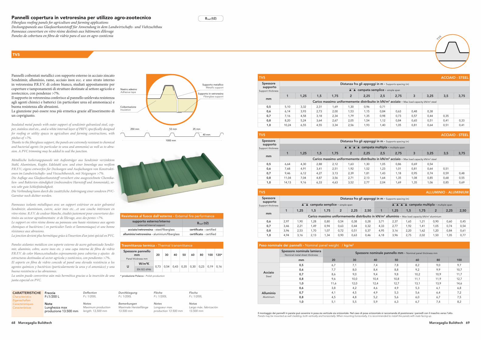
53 mm 25 mm250 mm
1000 mm
40 mm
Il montaggio dei pannelli in parete può avvenire in posa sia verticale sia orizzontale. Nel caso di posa orizzontale si raccomanda di posizionare i pannelli con il maschio verso l’alto. Panels may be mounted as wall cladding, both vertically and horizontally. When mounting horizontally, it is recommended to install the panels with male facing up.
Pannelli copertura in vetroresina per utilizzo agro-zootecnico Fiberglass roofing panels for agriculture and farming applicationsDeckungspaneele aus Glasfaserkunststoff für Anwendung in dem Landwirtschafts- und ViehzuchtbauPanneaux couverture en vitro résine destinés aux bâtiments d’élevagePaneles de cobertura en fibra de vidrio para el uso en agro-zootécnia
TV5
CARATTERISTICHECharacteristicsEigenschaftenCaractéristiquesCaracterísticas
FrecciaF≤1/200 L
NoteLunghezza max produzione 13.500 mm
DeflectionF≤ 1/200L
NotesMaximum production length: 13,500 mm
DurchbiegungF≤ 1/200L
BemerkungenMaximale Herstelllänge 13.500 mm
FlècheF≤ 1/200L
NotesLongueur max. production 13 500 mm
FlechaF≤ 1/200L
NotasLargo máx. fabricación 13.500 mm
TV5 ACCIAIO - STEEL
Spessore supporto
Support thickness
Distanza fra gli appoggi in m - Supports spacing (m)
campata semplice - simple span
mm 1 1,25 1,5 1,75 2 2,25 2,5 2,75 3 3,25 3,5 3,75
Carico massimo uniformemente distribuito in kN/m2 acciaio - Max load capacity kN/m2 steel
0,5 5,10 3,32 2,31 1,69 1,30 0,96 0,71
0,6 6,14 3,93 2,73 2,00 1,53 1,15 0,84 0,63 0,48 0,38
0,7 7,16 4,58 3,18 2,34 1,79 1,35 0,98 0,73 0,57 0,44 0,35
0,8 8,20 5,24 3,64 2,67 2,05 1,54 1,12 0,84 0,65 0,51 0,41 0,33
1,0 10,24 6,55 4,55 3,34 2,56 1,93 1,40 1,05 0,81 0,64 0,51 0,41
TV5 ACCIAIO - STEEL
Spessore supporto
Support thickness
Distanza fra gli appoggi in m - Supports spacing (m)
campata multipla - multiple span
mm 1 1,25 1,5 1,75 2 2,25 2,5 2,75 3 3,25 3,5 3,75
Carico massimo uniformemente distribuito in kN/m2 acciaio - Max load capacity kN/m2 steel
0,5 6,64 4,30 2,88 2,12 1,63 1,30 1,05 0,86 0,69 0,54
0,6 7,68 4,91 3,41 2,51 1,92 1,52 1,23 1,01 0,81 0,64 0,51
0,7 9,46 6,12 4,27 3,13 2,39 1,81 1,43 1,18 0,95 0,74 0,59 0,48
0,8 11,04 7,04 4,87 3,56 2,71 2,13 1,64 1,35 1,08 0,85 0,68 0,55
1,0 14,13 9,16 6,33 4,63 3,52 2,77 2,04 1,69 1,35 1,06 0,85 0,69
TV5 ALLUMINIO - ALUMINIUM
Spessore supporto
Support thickness
Distanza fra gli appoggi in m - Supports spacing (m)
campata semplice - simple span campata multipla - multiple span
mm 1 1,25 1,5 1,75 2 2,25 2,50 1 1,25 1,5 1,75 2 2,25 2,50
Carico massimo uniformemente distribuito in kN/m2 alluminio - Max load capacity kN/m2 aluminium
0,6 2,97 1,90 1,28 0,80 0,54 0,38 0,28 3,71 2,37 1,65 1,21 0,90 0,60 0,45
0,7 3,46 2,21 1,49 0,94 0,63 0,44 0,32 4,33 2,77 1,92 1,41 1,05 0,74 0,54
0,8 3,96 2,53 1,70 1,07 0,72 0,51 0,37 4,95 3,16 2,20 1,62 1,20 0,84 0,61
1,0 4,94 3,16 2,13 1,34 0,90 0,63 0,46 6,18 3,96 2,75 2,02 1,50 1,05 0,77
Pannelli coibentati metallici con supporto esterno in acciaio zincato Sendzimir, alluminio, rame, acciaio inox ecc. e uno strato interno in vetroresina P.R.F.V. di colore bianco, studiati appositamente per coperture e tamponamenti di strutture destinate al settore agricolo e zootecnico, con pendenze >7%.Il supporto in vetroresina conferisce al pannello un’elevata resistenza agli agenti chimici e batterici (in particolare urea ed ammoniaca) e buona resistenza alle abrasioni. La giunzione può essere resa più ermetica grazie all’inserimento di un coprigiunto.
Insulated metal panels with outer support of sendzimir galvanized steel, cop-per, stainless steel etc., and a white internal layer of PRFV, specifically designed for roofing or utility spaces in agriculture and farming constructions, with pitches of >7%.Thanks to the fiberglasss support, the panels are extremely resistant to chemical and bacterial agents (in particular to urea and ammonia) as well as to abra-sion. A PVC trimming may be added to seal the junction.
Metallische Isolierungspaneele mit Außenträger aus Sendzimir verzinktem Stahl, Aluminium, Kupfer, Edelstahl usw. und einer Innenlage aus weißem P.R.F.V.; eigens entworfen für Deckungen und Ausfachungen von Konstrukti-onen im Landwirtschafts- und Viezuchtbereich, mit Neigungen >7%. Die Auflage aus Glasfaserkunststoff versichert eine ausgezeichnete Chemika-lien- und Bakterien-ständigkeit (insbesondere Harnstoff und Ammoniak), so-wie sehr gute Schleifständigkeit.Die Verbindung kann durch die zusättzliche Anbringung einer sonderen PVC-Garnitur noch dichter werden.
Panneaux isolants métalliques avec un support extérieur en acier galvanisé Sendmizir, aluminium, cuivre, acier inox etc…et une couche intérieure en vitro résine. R.F.V. de couleur blanche, étudiés justement pour couvertures des-tinées au secteur agroalimentaire et de l’élevage, avec des pentes >7%.Le support en vitro résine donne au panneau une haute résistance aux agents chimiques et bactériens ( en particulier l’urée et l’ammoniaque) et une bonne résistance aux abrasions.La jonction devient plus hermétique grâce à l’insertion d’un joint spécial en PVC.
Paneles aislantes metálicos con soporte externo de acero galvanizado Sendzi-mir, aluminio, cobre, acero inox etc. y una capa interna de fibra de vidrio P.R.F.V. de color blanco,estudiados expresamente para cubiertas y ajustes de estructuras destinadas al sector agrícola y zootécnico, con pendientes >7%.El soporte en fibra de vidrio concede al panel una elevada resisténcia a los agentes químicos y bactéricos (particularmente la urea y el amoniáco) y una buena resisténcia a las abrasiones.La unión puede convertirse aún más hermética gracias a la inserción de una junta especial en PVC.
TV5
Trasmittanza termica - Thermal transmittance
Spessore pannello mm
Panel thickness mm
20 30 40 50 60 80 100 120*
UW/m2K
0,73 0,54 0,43 0,35 0,30 0,23 0,19 0,16EN ISO 6946
Peso nominale dei pannelli - Nominal panel weight / kg/m2
Spessore nominale lamiera Nominal metal sheet thickness
Spessore nominale pannello mm - Nominal panel thickness mm
mm 20 30 40 50 60 80 100
Acciaio Steel
0,5 6,7 7,1 7,4 7,8 8,2 9,0 9,7
0,6 7,7 8,0 8,4 8,8 9,2 9,9 10,7
0,7 8,6 9,0 9,4 9,8 10,2 10,9 11,7
0,8 9,6 10,0 10,4 10,8 11,1 11,9 12,7
1,0 11,6 12,0 12,4 12,7 13,1 13,9 14,6
Alluminio Aluminium
0,6 3,8 4,2 4,6 4,9 5,3 6,1 6,8
0,7 4,1 4,5 4,9 5,3 5,6 6,4 7,2
0,8 4,5 4,8 5,2 5,6 6,0 6,7 7,5
1,0 5,1 5,5 5,9 6,3 6,7 7,4 8,2
Nastro adesivoAdhesive tape
CoibentazioneInsulation
Supporto in vetroresinaFiberglass support
Supporto metallicoMetallic support
* produzione Polacca - Polish production
68 Marcegaglia Buildtech Marcegaglia Buildtech 69
Resistenza al fuoco dall’esterno - External fire performance
supporto esterno/internoexternal/internal support
Broof (t2)
acciaio/vetroresina - steel/fiberglass certificato - certified
alluminio/vetroresina - aluminium/fiberglass certificato - certified
Broof (t2)

T13 MONO ACCIAIO - STEEL
Spessore supporto
Support thickness
Distanza fra gli appoggi in m - Supports spacing (m)
campata semplice - simple span campata multipla - multiple span
mm 1 1,25 1 1,25 1,50
Carico massimo uniformemente distribuito in kN/m2 acciaio - Max load capacity kN/m2 steel
0,4 1,10 - 1,80 0,90 -
0,5 1,84 0,88 3,06 1,50 0,88
0,6 2,18 1,09 3,60 1,84 1,02
T13 MONO ALLUMINIO - ALUMINIUM
Spessore supporto
Support thickness
Distanza fra gli appoggi in m - Supports spacing (m)
campata semplice - simple span campata multipla - multiple span
mm 1 1,25 1 1,25 1,50
Carico massimo uniformemente distribuito in kN/m2 alluminio - Max load capacity kN/m2 aluminium
0,5 0,61 - 1,00 0,50 -
0,6 0,73 0,36 1,20 0,61 0,34
Peso nominale dei pannelli - Nominal panel weight
Spessore nominale lamiera Nominal metal sheet thickness
Peso medio kg/m2 - Average weight kg/m2
mm Acciaio - Steel Alluminio - Aluminium
0,4 4,6 -
0,5 5,7 2,5
0,6 6,8 2,9
PROPRIETÀ AUTOCENTINANTI (su appoggio continuo)Il pannello T13 MONO ACCIAIO può essere installato su pareti e coperture curve con raggio di curvatura minimo di 15 m. Raggi di curvatura inferiori (minimo 12 m) sono possibili adottando particolari accorgimenti in fase di montaggio.
SELF-CAMBERING PROPERTIES (on continuous support)The steel panel T13 MONO can be installed on walls and curved roofing with minimum radius of curvature of 15 m. Installation with lower radii (minimum 12 m) are feasible provided that specific solutions are implemented during the assembly phase.
COLORI STANDARD STANDARD COLORS:• M1301, bianco grigio • grey white• M4301, rosso siena • rosso siena• M5301, marrone testa di moro • marrone testa di moro
Su richiesta possono essere previsti tutti i colori simili a quelli contenuti nella cartella RAL.Upon request, all colours similar to the RAL range can be manufactured.
Pannelli monolamiera per rivestimento di pareti e copertureSingle sheet wall and roofing panelsWand- und Verkleidungspaneele mit einseitigem DeckblechPanneaux mono-tôle pour revêtement de parois et toitures Paneles metálicos monohoja para revestimiento de paredes y cubiertas
T13 MONO
T13
CoibentazioneInsulation
Supporto metallicoMetallic support
Nastro adesivoAdhesive tape
Film polietilenePolyethylene film
77 mm 24 mm 24 mm 33 mm
1000 mm
Pannelli monolamiera con greche trapezoidali simmetriche impiegabili per il rivestimento e l’impermeabilizzazione di pareti e coperture piane o a modesta curvatura di fabbricati ad uso industriale, commerciale o residenziale.
Insulated metal panels with symmetrical trapezoidal corrugations for the clad-ding and waterproofing of walls and roofings (flat or with limited curvature) in industrial, commercial or residential buildings.
Metallische Isolierungspaneele mit symmetrischen Trapezblechen für die Ver-kleidung und Abdichtung von Wänden und Dächern (flach oder mit begrenz-ter Krümmung) im Industrie-, Gewerbe- und Wohnbau.
Panneaux mono-tôle avec des méandres de forme trapézoïdale, symétriques et utilisables pour le revêtement et l’imperméabilisation de parois et toitures planes ou légèrement courbées de bâtiments à usage industriel, commercial ou résidentiel.
Paneles aislados metálicos con grecas trapezoidales simétricas utilizables para el revestimiento y la impermeabilización de paredes y de cubiertas planas o de baja curvatura de edificios industriales, comerciales o residenciales.
CARATTERISTICHECharacteristicsEigenschaftenCaractéristiquesCaracterísticas
Finitura internaFilm sottile di polietilene (standard)
Trasmittanza termica U=0,92 W/m²K (UNI EN ISO 6946)
Internal side finishingPolyethylene thin film (standard)
Thermal trasmittance U=0,92 W/m²K (UNI EN ISO 6946)
Interne OberflächenbearbeitungDünne Polyäthylenfolie (Standard)
Wärmedurchgang U=0,92 W/m²K (UNI EN ISO 6946)
Finition interneMince film de polyéthylène (standard)
Coefficient de transmission thermique U=0,92 W/m²K (UNI EN ISO 6946)
Acabado interiorPelícula fina de polietileno (estándar)
Transmitancia térmica U=0,92 W/m²K (UNI EN ISO 6946)
Marcegaglia Buildtech 7170 Marcegaglia Buildtech Marcegaglia Buildtech 71

72 Marcegaglia Buildtech Marcegaglia Buildtech 7372 Marcegaglia Buildtech Marcegaglia Buildtech 73

74 Marcegaglia Buildtech Marcegaglia Buildtech 75
* simile al * similar to
rosso tegola tile red
M 4104
avorio chiaro light ivory
RAL 1015 *
grigio ombra umbra grey
RAL 7022 *
grigio antracite anthracite grey
RAL 7016 *
verde reseda reseda green
RAL 6011 *
verde muschio moss green
RAL 6005 *
blu grigiastro grey blue
RAL 5008 *
blu genziana gentian blue
RAL 5010 *
rosso Siena “Siena” red
M 4301
Coppo siracusanoCoppo siracusano
Coppo anticato scuroCoppo antique dark
Coppo anticato chiaroCoppo antique light
grigio luce light grey
RAL 7035 *
testa di moro testa di moro
M 5301
bianco grigio grey white
M 1301
bianco puropure white
RAL 9010 *
alluminio brillantewhite aluminium
RAL 9006 *
Su richieSta è poSSibile concordare una combinazione perSonalizzata di qualità del materiale zincato e dei cicli vernicianti Su entrambe le facce
Upon reqUest, a cUstomized combination of galvanized materials and painting cycles can be arranged on both sides
Rivestimenti con finiture architettonicheArchitectural finish coatingsVerkleidungen mit architektonischem FinishRevêtements avec finitions architecturalesRevestimiento con acabados arquitectónicos
Gamma principali coloriMain colour range Hauptfarbpalette Gamme couleurs principales Gama de colores principales
Principali sistemi verniciantiStandard painting systems Hauptlackierungssysteme Principaux systèmes de vernissage Principales sistemas de pintura
MP3MP5MP10MP20MPHR
74 Marcegaglia Buildtech
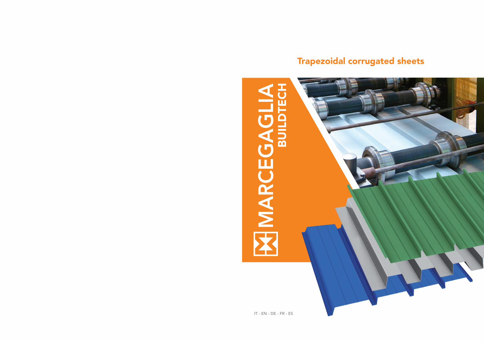
Trapezoidal corrugated sheets
IT - EN - DE - FR - ES

78 Marcegaglia Buildtech Marcegaglia Buildtech 79
steel building the world

80 Marcegaglia Buildtech Marcegaglia Buildtech 81
Marcegaglia è un gruppo industriale leader mondiale nella tra-sformazione dell’acciaio, con 5,6 milioni di tonnellate lavorate ogni anno. Dalla prima trasformazione, nell’ambito della propria filiera produttiva controllata, Marcegaglia ricava la gamma più ampia al mondo di semilavorati e prodotti finiti in acciaio.
Marcegaglia is the leading industrial group worldwide in the steel process-ing sector, with a yearly output of 5.6 million tons. After first transforma-tion, within its controlled value chain Marcegaglia develops the world’s widest range of steel semi-products and finished goods.
Marcegaglia ist der weltweit führende Industriekonzern im Bereich Stahlum-wandlung mit jährlich 5,6 Millionen Tonnen verarbeitetem Stahl. Aus der ersten Umwandlung innerhalb der eigenen, kontrollierten Produktionskette erzeugt Marcegaglia das weltweit umfangreichste Sortiment an Halb- und Fertigerzeugnissen.
Marcegaglia est le groupe industriel leader mondial de la transformation de l’acier avec 5,6 millions de tonnes usinées chaque année. De la première trans-formation, dans sa propre filière de production contrôlée, Marcegaglia obtient la gamme de produits semi-ouvrés et de produits finis en acier la plus étendue du monde.
Marcegaglia es el grupo industrial líder mundial en la transformación del acero, con 5,6 millones de toneladas trabajadas cada año. Desde la primera transformación en el ámbito de su hilera productiva controlada, Marcegaglia obtiene la gama de semiproductos y productos acabados en acero más amplia a escala mundial.
Elementi grecatiTrapezoidal corrugated sheetsTrapezblecheÉléments nervurésElementos grecados
La gamma Marcegaglia Buildtech di elementi grecati in acciaio e al-luminio per pareti, coperture e coperture deck è parte della filiera produttiva certificata di semilavorati e prodotti finiti in acciaio per applicazioni nel settore dell’edilizia civile e industriale.
La produzione è interamente realizzata nel più grande e moderno sta-bilimento italiano specializzato di Pozzolo Formigaro (Nord Italia), recentemente ampliato e rinnovato con le ultime tecnologie produtti-ve per garantire qualità e innovazione di prodotto, e nello stabilimen-to di Praszka (Polonia).
The Marcegaglia Buildtech range of steel and aluminium corrugated sheets for use on walls, roofs and decking forms part of the certified production chain of unfinished and finished steel products for applications in the civil and indust-rial construction sector.
They are entirely manufactured in Italy’s largest, most modern specialist plant at Pozzolo Formigaro (northern Italy), recently expanded and renewed with the latest production technologies to guarantee product quality and innova-tion, and at the Praszka (Poland) plant.
Das Sortiment Marcegaglia Buildtech an Trapezblechen aus Stahl und Alumi-nium für Wände, Verkleidungen und Deck-Verkleidungen ist Teil der zertifi-zierten Produktionskette von halbfertigen und fertigen Stahlerzeugnissen zur Anwendung im Zivil- und Industriebauwesen.
Die komplette Fertigung erfolgt im größten und modernsten italienischen Spezialwerk in Pozzolo Formigaro (Norditalien), das erst kürzlich erweitert und mit den neuesten Herstellungstechnologien ausgestattet wurde, um Qua-lität und Produktinnovation zu gewährleisten, sowie in dem Werk in Praszka (Polen).
La gamme Marcegaglia Buildtech d’éléments nervurés en acier et aluminium pour murs, couvertures et couvertures deck fait partie de la filière de produc-tion certifiée de produits semi-finis et finis en acier pour des applications dans le secteur des constructions civiles et industrielles.
La production est entièrement réalisée dans le plus grand établissement italien moderne spécialisé de Pozzolo Formigaro (nord de l’Italie), agrandi dernière-ment et rénové selon les dernières technologies productives afin de garantir la qualité et l’innovation du produit, ainsi que dans l’établissement de Praszka (Pologne).
La gama Marcegaglia Buildtech de elementos grecados en acero y aluminio para paredes, cubiertas y cubiertas deck forma parte de la cadena de produc-ción certificada de productos semiacabados y acabados de acero para aplica-ciones en el sector de la construcción civil e industrial.
La producción se realiza íntegramente en la planta especializada italiana más grande y moderna de Pozzolo Formigaro (al norte de Italia), recientemente ampliada y renovada con las últimas tecnologías de producción para garan-tizar la calidad e innovación del producto, así como en la planta de Praszka (Polonia).

SUPPORTIMetallic supportsSchalenSupportsSoportes
Acciaio zincato EN 10346 con procedimento “Sendzimir”. Qualità dell’acciaio: unificate e non, secondo richiesta. Preverniciati secondo EN 10169 (Coil Coating) in base alle norme ECCA ed EURONORME:
di produzione normale: - con rivestimento poliestere
di produzione speciale: - con rivestimento SUPER POLIESTERE- con rivestimento PVDF fluoruro di polivinile
Altri materiali: alluminio, rame, inox, corten, aluzinc.
Sendzimir Galvanized steel EN 10346
Steel quality: unified or not, when required.Pre-painted steel according to EN 10169 (coil coating) and to ECCA norms and EURONORMS:
standard production: - with polyester coating
special production: - with SUPER-POLYESTER coating- with PVDV polyvinyl fluoride coating
Further materials: aluminum, copper, stainless steel, corten, aluzinc.
Verzinkter Stahl nach EN 10346 durch “Sendzimir” Verfahren.
Stahlgüte: normiert und nicht, je nach Anfrage.Beschichtet nach EN 10169 (Coil Coating) und gemäss ECCA Richtlinien und EURONORMEN:
normale Fertigung: - mit Polyesterüberzug
Sonderfertigung: - mit SUPER- POLYESTER-Überzug- mit PVDF Polyvinyl- Fluorid-Überzug
Weitere Materialien: Aluminium, Kupfer, Edelstahl, Corten, Aluzinc.
Acier galvanisé EN 10346 selon le procédé « Sendzimir ».
Qualités de l’acier: standardisées ou non selon la demande.Pré-vernis selon EN 10169 (Coil Coating) en fonction des normes ECCA et EURONORME:
de production normale: - avec revêtement en polyester
de production spéciale: - avec revêtement en SUPER POLYESTER- avec revêtement en PVDF fluorure
De polyvinyleautres matériaux: aluminium, cuivre, inox, corten, aluzinc.
Acero galvanizado EN 10346 con procedimiento “Sendzimir”.
Calidades del acero: unificadas y no unificadas, según pedido. Prelacados según EN 10169 (Coil Coating) conforme a las normas ECCA y EURONORME:
de producción normal: - con revestimiento poliester
de producción especial: - con revestimiento SUPER POLIESTER- con revestimiento PVDF fluoruro de polivinilo
Otros materialesi: aluminio,cobre, inox, corten, aluzinc.
TOLLERANZETolerancesToleranzenTolérancesTolerancias
Sullo spessore EN 10143
Sulla lunghezza ± 5 mm (salvo accordi)
On the thickness EN 10143
On the lenght ± 5 mm (Unless special agreements made)
Bei der Stärke EN 10143
Bei der Länge ± 5 mm (Vereinbarunge vorbehalten)
Sur l’épaisseur EN 10143
Sur la longueur ± 5 mm (sauf accords)
En el espesor EN 10143
En la longitud ± 5 mm (salvo acuerdos)
LUNGHEZZALengthLängeLongueur Longitud
Massima realizzabile m 16
Minima realizzabilem 0,50
Maximum possiblem 16
Minimum possiblem 0.50
herstellbares Maximum m 16
herstellbares Minimum m 0,50
Maximale réalisable m 16
Minimale réalisable m 0,50
Máxima realizable m 16
Mínima realizable m 0,50
CENTINATURARidge girders WölbenCintrageEstructura de soporte
Possibilità di fornitura di elementi per copertura a volta con ampissime possibilità di raggi.
Possibility of supplying vault roofing elements with extremely broad radius possibilities.
Möglichkeit der Lieferung von Gewölbeabdeckungs-elementen mit umfangreichen Radiusmöglichkeiten.
Possibilité de fourniture d’éléments pour couverture à voûte avec de très larges possibilités de rayons.
Posibilidad de suministro de elementos para cubierta abovedada con numerosas posibilidades de radios.
IMBALLOPackagingVerpackungEmballageEmbalaje
Materiale zincato serie commerciale in pacchi da 50 fogli cadauno. Per ordini su commessa la composizione in colli omogenei. Materiale preverniciato in colli avvolti in polietilene. Tutti i colli saranno protetti con angolari zincati nei punti baricentrici.
Commercial range galvanised material in packs of 50 sheets each. For job orders homogenous cartons made up. Coated material in cartons wrapped in polythene.All the cartons will be protected with galvanised angle-iron at the barycentres.
Verzinktes Material der handelsüblichen Serie in Paketen zu jeweils 50 Blättern. Bei Aufträgen auf Kommission Zusammenstellung in homogene Kolli. Vorgestrichenes Material in mit Polyäthylen umwickelten Kolli.Alle Kolli werden mit an den Schwerpunkten verzinkten Eckstücken geschützt.
Matériau galvanisé, série commerciale, en paquets de 50 feuilles chacun. Pour ordres sur commande la composition en colis homogènes. Matériau pré-peint en colis enveloppés dans du polyéthylène. Tous les colis seront protégés par des cornières galvanisées dans les points barycentriques.
Material galvanizado serie comercial en paquetes de 50 chapas cada uno. Para suministros bajo pedido, composición de paquetes homogéneos. Material prelacado en paquetes envueltos en polietileno. Todos los paquetes serán protegidos por angulares galvanizados en los puntos baricéntricos.
IMBALLOPackagingVerpackungEmballageEmbalaje
L’imballo di cui sopra e le tavole distanziali vengono valutati tara per merce. Altri imballi di tipo particolare dovranno essere valutati a parte.
The packaging mentioned above and the spacers are included in the total tare of the goods. Any other special packaging must be assessed apart.
Die o.g. Verpackung und die Abstandsplatten werden als Tara gerechnet. Andere, spezielle Verpackungen müssen gesondert bewertet werden.
La tare comprend l’emballage ci-dessus ainsi que les planches d’entretoise. D’autres emballages de type particulier devront être évalués séparément.
La tara comprende el embalaje descrito anterior-mente así como las tablas separadoras. Otros embalajes de tipo especial se deberán considerar aparte.
AVVERTENZEDirectionsWarnhinweiseInstructionsAdvertencias
Allo scopo di evitare alterazioni allo strato superficiale degli elementi grecati quale la formazione di ruggine bianca e fenomeni di ossidazione si consigliano le seguenti precauzioni:
- Il materiale deve sempre viaggiare ed essere stivato al riparo dalla pioggia, neve, nebbia e umidità.
- Il tempo di stivaggio in pacchi del materiale zincato deve essere ridotto al minimo indispensabile.
- I pacchi di elementi grecati avvolti in polietilene devono avere una limitata permanenza in tali condizioni, onde evitare formazione di condensa, causa primaria della ruggine.
- Il materiale deve essere quindi aperto oppure posto in condizioni di massima ventilazione.
- Il materiale zincato o preverniciato deve essere stivato a debita distanza da fonti di pulviscolo ferroso, di esalazioni chimiche e di fuliggine dovuta alla combustione di gasolio che sono causa di un precoce processo di corrosione.
To prevent alteration to the surface layer of the trapezoidal corrugated sheets such as the formation of white rust, and oxidisation, we recommend taking the following precautions:
- The material must always travel protected from rain, snow, fog and humidity.
- The time the galvanised material is stowed in packs must be kept to the minimum indispensable time.
- The packs of trapezoidal corrugated sheets wrapped in polythene must be kept in this condition for the shortest time possible to prevent the formation of condensation, the primary cause of rust.
- The material must therefore be open or placed in conditions of maximum ventilation.
- The galvanised or coated material must be stowed at a good distance from ferrous dust, chemical fumes, and soot from fuel oil combustion which can cause precocious corrosion.
Um Veränderungen in der Oberflächenschicht der Trapezbleche wie die Bildung von weißem Rost und Oxydations-phänomene zu vermeiden, werden die folgenden Vorsichtsmaßnahmen empfohlen:
- Das Material muss stets vor Regen, Schnee, Nebel und Feuchtigkeit geschützt transportiert und verstaut werden.
- Die Verstauung des verzinkten Materials in Paketen muss auf den geringst möglichen Zeitraum begrenzt werden.
- Die m it Polyäthylen umhüllten Pakete der Riffelblechelemente dürfen nur für einen begrenzten Zeitraum in diesem Zustand verbleiben, um die Bildung von Kondenswasser zu vermeiden, dem Hauptverursacher von Rost.
- Das Material muss also offen sein, oder mit grösstmöglicher Belüftung aufbewahrt werden.
- Das verzinkte oder vorgestrichene Material muss in geeigneter Entfernung von Eisenstaub, chemischen Ausdünstungen und aus der Verbrennung von Diesel entstandenem Russ verstaut werden, die einen vorzeitigen Korrosionsprozess verursachen würden.
Dans le but d’éviter les altérations de la couche superficielle des éléments travaillés telles que la formation de rouille blanche et les phénomènes d’oxydation, les précautions suivantes sont conseillées:
- Le matériau doit toujours voyager et être arrimé à l’abri de la pluie, de la neige, du brouillard et de l’humidité.
- Le temps d’arrimage en paquets, du matériau gal-vanisé, doit être réduit au minimum indispensable.
- Les paquets d’éléments travaillés, enveloppés dans du polyéthylène, doivent avoir une permanence limitée dans de telles conditions, afin d’éviter la formation de vapeur d’eau condensée, première cause de ruille.
- Le paquet doit donc être ouvert ou placé en condi-tion de ventilation maximale.
- Le matériau galvanisé ou pré-peint doit être arrimé à une distance convenable des sources de poussières ferreuses, d’émanations chimiques et de suie due à la combustion de gasoil, qui sont la cause d’un processus précoce de corrosion.
Con el fin de evitar alteraciones en la superficie de los elementos grecados, tal como la formación de óxido de cinc y otros fenómenos de oxidación, le aconsejamos respetar las siguientes precauciones:
- El material debe siempre viajar y almacenarse protegido de lluvias, nieve, nieblas y humedad.
- El tiempo de permanencia en paquetes del material galvanizado, debe reducirse al mínimo indispensable.
- Con el fin de evitar la condensación (que representa la causa primaria del óxido), los paquetes compuestos por elementos grecados y envueltos en polietileno, pueden permanecer en dichas condiciones durante un tiempo limitado.
- Por esta razón, el material debe abrirse o ponerse en condiciones de máxima ventilación.
- El material galvanizado o prelacado debe almacenarse lejos de fuentes de partículas ferrosas, exhalaciones químicas y hollín debido a la combustión de gasoil, ya que dichos elementos pueden causar un proceso precoz de corrosión.
Specifiche tecniche - Elementi grecatiTechnical specifications - Trapezoidal corrugated sheetsSpezifikationen - TrapezblecheSpécifications techniques - Eléments travaillésEspecificaciones técnicas - Elementos grecados
82 Marcegaglia Buildtech Marcegaglia Buildtech 83

CARATTERISTICHECharacteristics EigenschaftenCaractéristiquesCaracterísticas
Copertura e parete semplice: soluzione prevista quando si richiede esclusivamente impermeabilità all’acqua, alla neve, al vento, nonché resistenza all’urto della grandine.
Roofing and simple walling: solution foreseen when exclusively water, snow and wind proofing is required as well as resistance to the impact of hail.
Einfache Abdeckung und Wand: Vorgesehene Lösung für den Fall, dass ausschließlich die Abdichtung gegen Wasser, Schnee, Wind, sowie Hagelschlagfestigkeit benötigt wird.
Couverture et mur simple: solution prévue lorsque l’on demande exclusivement l’imperméabilité à l’eau, à la neige, au vent, ainsi que la résistance à la chute de grêle.
Cubierta y pared simple: la solución está prevista, cuando se requiere exclusivamente impermeabilidad al agua, nieve, viento e, incluso, resistencia al impacto del granizo.
CRITERI DI CALCOLOCalculation criteriaKalkulationskriterienCritières de calculCriterios de cálculo
L’approccio generale del calcolo è quello dell’Eurocodice 3 “Progettazione delle strutture di acciaio”, Parte 1-3 “Regole supplementari per elementi sottili formati a freddo”. Il calcolo è stato condotto secondo il metodo degli Stati Limite: le verifiche tensionali sono state pertanto sviluppate come Stati Limite Ultimi, mentre quelle tipo deformativo come Stati Limite di Servizio.
Noti gli schemi statici e i valori delle caratteristiche resistenti limite, i valori del carico utile massimo uniformemente distribuito, e le relative luci d’impiego, rispondono ai seguenti criteri:
- i valori indicati in carattere normale (riga superiore) rappresentano i carichi che gli elementi grecati possono sopportare nel rispetto di tutte le modifiche contemplate dal presente calcolo;
- i valori indicati in carattere grassetto (riga inferiore) rappresentano i carichi che gli elementi grecati possono sopportare senza rispettare alcuna limitazione di freccia.
The Eurocode 3 “Design of steel structures”, Part 1-3 “Supplementary rules for cold-formed thin gauge members and sheeting” provides the general approach for calculation; the Limit State method applied: the tension tests were hence considered as Ultimate Limit States, while the deformation tests as Service Limit States.
Once the static patterns and the limit values of the resistant parameters are known, the max. uniformly distributed live load allowance, and the related application bays, follow this behavior:
- the values written in normal font (upper line) represent the loads that the trapezoidal corrugated elements may bear within the possible modifications contemplated by these figures;
- the values written in bold (lower line) represent the loads that the trapezoidal corrugated elements may bear without any limitation on the straightness deviation.
Die allgemeine Berechnungsgrundlage ist der Eurocode 3 “Bemessung und Konstruktion von Stahlbauten“ - Teil 1-3 “Allgemeine Bemessungsregeln - Ergänzende Regeln für kaltgeformte dünnwandige Bauteile und Bleche”. Die Berechnung erfolgte nach dem Methode des Grenzzustandes: die Spannung wurde als Letzter Grenzzustand geprüft, während die Verformung als Betrieb Grenzzustand.
Einmal die statischen Pläne und die Festigkeitsgrenzwerte bekannt sind, die max. Werte des gleichmäßig verteilten Nutzlast und die entsprechenden Anwendungsweiten lauten wie folgt:
- die in Normalschrift angegebenen Werte (Zeile oben) stellen die Lasten dar, die die Trapezteile unter den Varianten tragen, die in der Berechnung berücksichtigt wurden.
- die in Halbfettschrift angegebenen Werte (Zeile unten) stellen die Lasten dar, die die Trapezteile tragen, wenn der Geradheitsabweichung kein Grenzwert gestellt wird.
L’approche générale du calcul est celle de l’Eurocode 3 “Projet des structures en acier”, Parties 1-3 “Règles supplémentaires pour éléments fins moulés à froid”. Le calcul a été effectué selon la méthode des Stades Limites: par conséquent, les contrôles de la tension ont été développés en tant que Stades Limites Extrêmes, tandis que les contrôles de la déformation ont été définis en tant que Stades Limites de Service.
D’après les schémas statiques et les valeurs des caractéristiques résistantes limites, les valeurs de la charge utile maximale répartie uniformément, ainsi que les lumières d’utilisation correspondantes, répondent aux critères suivants:
- les valeurs indiquées en caractères normaux (ligne supérieure) représentent les charges que les éléments en forme de grecque peuvent supporter sous l’angle de toutes les modifications envisagées par ce calcul;
- les valeurs indiquées en caractères gras (ligne inférieure) représentent les charges que les éléments en forme de grecque peuvent supporter sans respecter aucune limitation de flèche.
La proximidad general del cálculo es el del Eurocódigo 3 “Proyectación de las estructuras de acero”, Parte 1-3 “Reglas suplementarias para elementos sutiles moldeados en frío”. El cálculo ha sido conducido según el método de los Estados Límite, las evaluaciones de tensión han sido por lo tanto desarrolladas como Estados Límite Últimos,mientras que aquellas de tipo deformativo como Estados Límite de Servicio.
Sabidos los esquemas estáticos y los valores de las características resistentes límite los valores del cargo útil máximo uniformemente distribuido, y las relativas luces de empleo responden a los siguientes criterios:
- los valores indicados en carácteres normales (línea superior) representan los cargos que los elementos grecados pueden soportar en el respeto de todas las variaciones contempladas por el presente cálculo;
- los valores indicados en caracteres en negrita (línea inferior) representan los cargos que los elementos grecados pueden soportar sin respetar alguna limitación de flecha.
CRITERI DI CALCOLOCalculation criteriaKalkulationskriterienCritières de calculCriterios de cálculo
Gli schemi statici, schematicamente illustrati in figura, sono quelli di trave in semplice appoggio o quelli di trave continua su due o più campate, con estremità in semplice appoggio.
Le verifiche contemplate dal presente calcolo sono le seguenti:- momento flettente positivo (in campata);- momento flettente negativo e taglio (appoggi di continuità);- taglio (appoggi di estremità);- freccia.
La limitazione sulla freccia è f ≤ L/200, dove L è la luce d’impiego (interasse fra gli appoggi).
The static patterns sketched by the illustration refer to the cases of an unfastened girder or of a continuous girder over two or more bays, with free ends.
These the tests considered by the calculation:
- positive bending moment (over the bay);- negative bending moment and cut (continuity bearings);
- cut (ends bearings);
- deviation.
The limit deviation is f ≤ L/200, where L is the application span (inter-axis between bearings).
Die im Bild gezeigten statischen Pläne betreffen unbefestigte Balken oder Balken über eine oder zwei Spannweiten mit unbefestigten Enden.
Die Berechnung nimmt die folgenden Prüfungen in Betracht:
- positiver Biegemoment (auf der Spannweite);- negativer Biegemoment und Schneiden (Stützen über die Spannweite);- Schneiden (Stützen an den Enden);- Geradheitsabweichung.
Die Grenzabweichung ist f ≤ L/200, wo L steht für die Anwendungsweite (Achsenabstand der Stützen).
Les schémas statiques, illustrés schématiquement sur la figure, sont ceux des sablières en simple appui ou d’une sablière continue sur deux ou plusieurs travées, dont les extrémités sont en simple appui.
Les contrôles envisagés par le présent calcul sont les suivants:
- moment fléchissant positif (en travée);- moment fléchissant négatif et découpe (appuis de continuité);
- découpe (appuis aux extrémités);- flèche.
La limitation sur la flèche est f ≤ L/200, L étant la lumière d’utilisation (écartement entre les appuis).
Los esquemas estáticos, ilustrados esquemáticamente con figuras, son los de viga en apoyo simple o los de viga contínua sobre dos o más travesaños, con estremidades en apoyo simple.
Las evaluaciones contempladas por el presente cálculo son las siguientes:- momento pliegue positivo ( en travesaño),- momento pliegue negativo y corte (apoyos de continuidad),
- corte (apoyos de extremidad),- flecha.
La limitación sobre la flecha es f ≤ L/200, donde L es la luz de empleo(eje central entre los apoyos).
Copertura e parete sempliceRoofing and simple wallingEinfache Abdeckung und WandCouverture et mur simpleCubierta y pared simple
84 Marcegaglia Buildtech Marcegaglia Buildtech 85

CAMPO D’IMPIEGOField of applicationAnwendungsbereichDomaine d’emploiCampo de empleo
Le tabelle si riferiscono ai tre casi di campata singola, doppia e multipla; negli ultimi due casi le campate s’intendono tutte della medesima luce (interasse fra le travi d’appoggio) e vincolate in modo bilatero sugli appoggi (ossia impedite di sollevarsi).Anche il carico, oltreché uniformemente distribuito, s’intende di valore costante e applicato per l’intero sviluppo della travata, nessuna campata esclusa.
The tables refer to the three cases of single bay, double bay and multiple bay. The last two types of bay feature the same span width (inter-axis between bearing girders) and are bound on both sides to the bearings (cannot rise). The load value, apart from being uniformly distributed, is constant and applies to the whole girder line, no bay excluded.
Die Tabellen betreffen die drei Arten von Spannweiten: einzelne, doppelte und mehrfache. Bei den letzten zwei Fällen weisen die Spannweiten dieselbe Maß auf (Achsenabstand zwischen Stützbalken) und sind an beiden Enden befestigt (heben unmöglich). Das Lastwert ist gleichmäßig verteilt, konstant und die ganze Ausdehnung des Balkensystems betreffend - keine Spannweite ausgeschlossen.
Les tables se réfèrent aux trois cas de portée individuelle, double et multiple; dans les deux cas derniers toutes les portées sont de la même lumière (entraxe entre les poutres d’appui) et liées de façon bilatérale sur les appuis (c’est-à-dire, qui ne peuvent pas se soulever). Le charge aussi, uniformement distribué, est de valeur constante et appliquée au développement entier de la poutre, aucune portée exclue.
Las tablas se refieren a los tres casos de travesaños unico,doble y múltiplo, en los últimos dos casos los travesaños se comprenden todos de la misma luz (eje central entre las vigas de apoyo) y vinculadas de manera bilateral sobre los apoyos (o sea imposibilitadas para levantarse),También la carga, además de estar distribuida de manera uniforme, se requiere de valor constante y aplicado durante el completo desarrollo de la puesta de las vigas, ningún travesaño excluido.
CRITERI DI DIMENSIONAMENTOSizing criteriaBemessungskriterienCritères de dimensionnementCriterios de dimensionamiento
Il carico utile indicato nelle tabelle è da intendersi come aggiuntivo rispetto al peso proprio della lamiera: qualsiasi altro peso, come ad esempio eventuali impermeabilizzazioni, coibentazioni o altre finiture, è da annoverare fra i carichi che vanno a comporre l’utile indicato nelle tabelle.
La giacitura delle lamiere s’intende piana e orizzontale, mentre i carichi si intendono verticali diretti verso il basso; per l’eventualità di posizione inclinata - ma comunque planare - delle lamiere, i carichi indicati in tabella s’intendono validi per la sola componente perpendicolare al piano di giacitura della lamiera, lasciando al progettista ogni valutazione riguardante la riduzione di portata dovuta alle altre componenti dei carichi.
The live load allowance given in the tables is additional to the plate’s own weight. Any other weight - such as those due to insulation, water tightness or other sort of finishing - stays within the loads that compose the live allowance reported by the tables.
The normal plates disposition is flat and horizontal, and the loads, on the contrary, are vertical and directed downward. In case of flat, yet inclined disposition of the plates, the loads reported by the table refer only to the component perpendicular to the plate’s disposition plane; the esteem of the capacity reduction due to the other loads’ components is left to the designer.
Der in der Tabellen erscheinende Nutzlast ist im Verhältnis mit dem Eigengewicht der Bleche zusätzlich zu lesen: jeder weitere Gewichtszusatz - z.B. wegen Dichten, Isolierungen oder andere Endbearbeitungen - gehört zu den Lasten, die den Nutzlast in der Tabellen aufbauen.
Das Liegen der Blechen ist flach und horizontal; die Lasten sind vertikal, dem Boden hinunter gerichtet. Bei schlief - jedoch flach - Blechpositionen, die Lastwerte in der Tabellen gelten nur für die senkrechte Komponente der Blechebene; dem Entwerfer ist die Bewertung der Tragfähigkeitabnahme aufgegeben, die von den anderen Gewichtskomponenten abhängt.
Le charge utile indiqué dans les tables doit être entendu comme un facteur additionnel avec respect au poids propre de la tôle: n’importe quel poids différent, comme par exemple de possibles imperméabilisations, isolements ou d’autres finissages, doit être compris entre les charges qui composent l’utile indiqué dans les tables.
La position des tôles est entendue plate et horizontale, tandis que les charges sont entendus verticales et directes vers le bas; pour une possible position inclinée - mais plate, toutefois - des tôles, les charges indiqués dans la table sont entendus valides pour la seule composante perpendiculaire au plan de position de la tôle, laissant au projecteur toute évaluation qui concerne la réduction de portée due aux autres composantes des charges.
El cargo útil indicado en las tablas debe considerarse como añadido con respecto al peso propio de la plancha: cualquier otro peso como por ejemplo eventuales impermeabilizaciones, aislamientos u otros acabados, deben computarse entre los cargos que componen el útil indicado en las tablas.
La posición de las planchas debe ser plana y horizontal, mientras que los cargos deben ser verticales dirigidos hacia abajo, por la posibilidad de posición inclinada -pero de cualquier modo plana- de las planchas, los cargos indicados en la tabla se consideran válidos solo para la componente perpendicular al piso de posición de las planchas, dejándo al proyectista cualquier valoración respectiva a la reducción de transporte debido a los otros componentes de los cargos.
86 Marcegaglia Buildtech Marcegaglia Buildtech 87Marcegaglia Buildtech 87
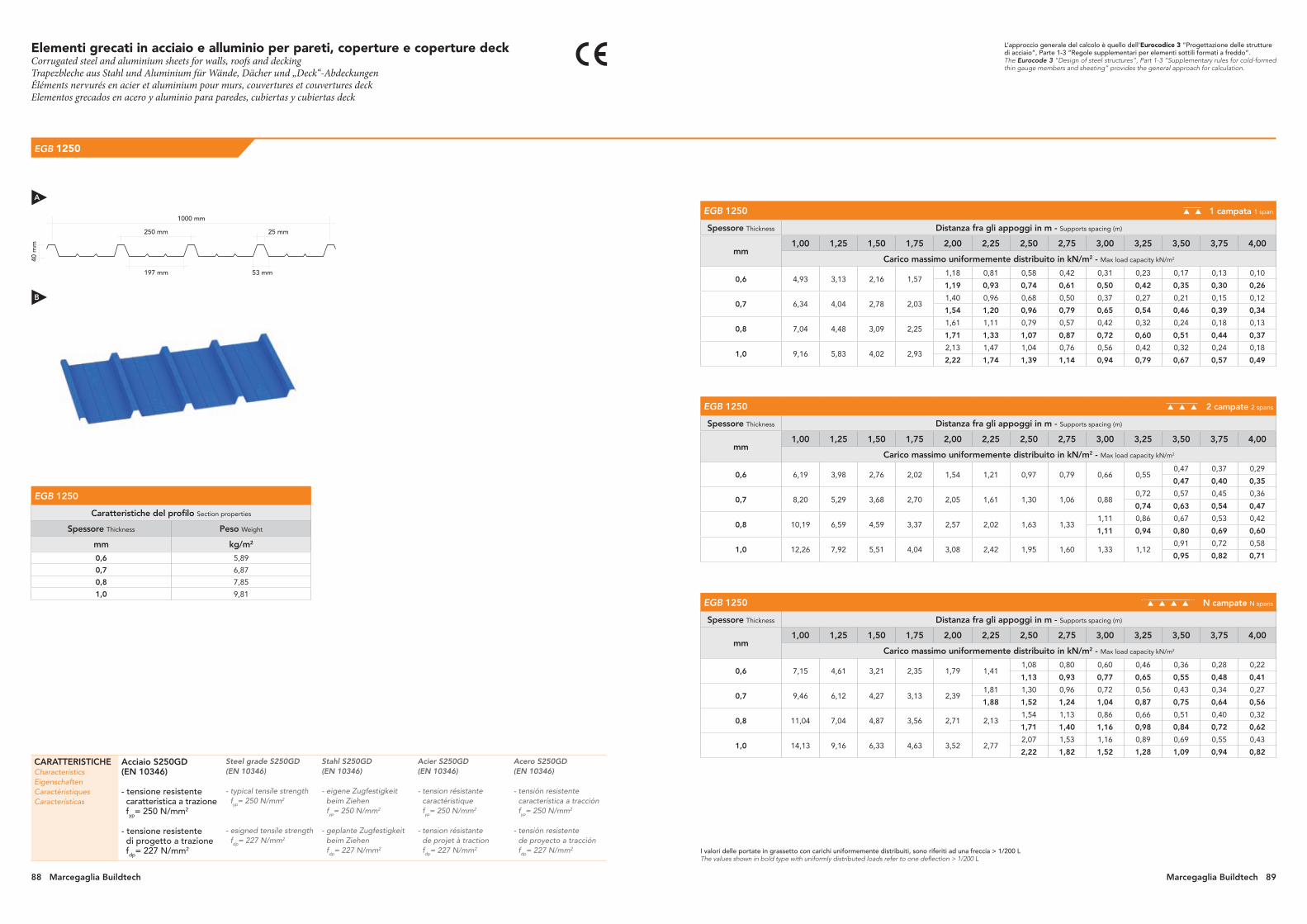
Elementi grecati in acciaio e alluminio per pareti, coperture e coperture deckCorrugated steel and aluminium sheets for walls, roofs and deckingTrapezbleche aus Stahl und Aluminium für Wände, Dächer und „Deck“-Abdeckungen Éléments nervurés en acier et aluminium pour murs, couvertures et couvertures deckElementos grecados en acero y aluminio para paredes, cubiertas y cubiertas deck
EGB 1250
EGB 1250 1 campata 1 span
Spessore Thickness Distanza fra gli appoggi in m - Supports spacing (m)
mm 1,00 1,25 1,50 1,75 2,00 2,25 2,50 2,75 3,00 3,25 3,50 3,75 4,00
Carico massimo uniformemente distribuito in kN/m2 - Max load capacity kN/m2
0,6 4,93 3,13 2,16 1,571,18 0,81 0,58 0,42 0,31 0,23 0,17 0,13 0,10
1,19 0,93 0,74 0,61 0,50 0,42 0,35 0,30 0,26
0,7 6,34 4,04 2,78 2,031,40 0,96 0,68 0,50 0,37 0,27 0,21 0,15 0,12
1,54 1,20 0,96 0,79 0,65 0,54 0,46 0,39 0,34
0,8 7,04 4,48 3,09 2,251,61 1,11 0,79 0,57 0,42 0,32 0,24 0,18 0,13
1,71 1,33 1,07 0,87 0,72 0,60 0,51 0,44 0,37
1,0 9,16 5,83 4,02 2,932,13 1,47 1,04 0,76 0,56 0,42 0,32 0,24 0,18
2,22 1,74 1,39 1,14 0,94 0,79 0,67 0,57 0,49
EGB 1250 2 campate 2 spans
Spessore Thickness Distanza fra gli appoggi in m - Supports spacing (m)
mm 1,00 1,25 1,50 1,75 2,00 2,25 2,50 2,75 3,00 3,25 3,50 3,75 4,00
Carico massimo uniformemente distribuito in kN/m2 - Max load capacity kN/m2
0,6 6,19 3,98 2,76 2,02 1,54 1,21 0,97 0,79 0,66 0,550,47 0,37 0,29
0,47 0,40 0,35
0,7 8,20 5,29 3,68 2,70 2,05 1,61 1,30 1,06 0,880,72 0,57 0,45 0,36
0,74 0,63 0,54 0,47
0,8 10,19 6,59 4,59 3,37 2,57 2,02 1,63 1,331,11 0,86 0,67 0,53 0,42
1,11 0,94 0,80 0,69 0,60
1,0 12,26 7,92 5,51 4,04 3,08 2,42 1,95 1,60 1,33 1,120,91 0,72 0,58
0,95 0,82 0,71
EGB 1250 N campate N spans
Spessore Thickness Distanza fra gli appoggi in m - Supports spacing (m)
mm 1,00 1,25 1,50 1,75 2,00 2,25 2,50 2,75 3,00 3,25 3,50 3,75 4,00
Carico massimo uniformemente distribuito in kN/m2 - Max load capacity kN/m2
0,6 7,15 4,61 3,21 2,35 1,79 1,411,08 0,80 0,60 0,46 0,36 0,28 0,22
1,13 0,93 0,77 0,65 0,55 0,48 0,41
0,7 9,46 6,12 4,27 3,13 2,391,81 1,30 0,96 0,72 0,56 0,43 0,34 0,27
1,88 1,52 1,24 1,04 0,87 0,75 0,64 0,56
0,8 11,04 7,04 4,87 3,56 2,71 2,131,54 1,13 0,86 0,66 0,51 0,40 0,32
1,71 1,40 1,16 0,98 0,84 0,72 0,62
1,0 14,13 9,16 6,33 4,63 3,52 2,772,07 1,53 1,16 0,89 0,69 0,55 0,43
2,22 1,82 1,52 1,28 1,09 0,94 0,82CARATTERISTICHECharacteristicsEigenschaftenCaractéristiquesCaracterísticas
Acciaio S250GD (EN 10346)
- tensione resistente caratteristica a trazione fyp= 250 N/mm2
- tensione resistente di progetto a trazione fdp= 227 N/mm2
Steel grade S250GD (EN 10346)
- typical tensile strength fyp= 250 N/mm2
- esigned tensile strength fdp= 227 N/mm2
Stahl S250GD (EN 10346)
- eigene Zugfestigkeit beim Ziehen fyp= 250 N/mm2
- geplante Zugfestigkeit beim Ziehen fdp= 227 N/mm2
Acier S250GD (EN 10346)
- tension résistante caractéristique fyp= 250 N/mm2
- tension résistante de projet à traction fdp= 227 N/mm2
Acero S250GD(EN 10346)
- tensión resistente característica a tracción fyp= 250 N/mm2
- tensión resistente de proyecto a tracción fdp= 227 N/mm2
1000 mm
250 mm 25 mm
53 mm197 mm
40 m
m
L’approccio generale del calcolo è quello dell’Eurocodice 3 “Progettazione delle strutture di acciaio”, Parte 1-3 “Regole supplementari per elementi sottili formati a freddo”.The Eurocode 3 “Design of steel structures”, Part 1-3 “Supplementary rules for cold-formed thin gauge members and sheeting” provides the general approach for calculation.
I valori delle portate in grassetto con carichi uniformemente distribuiti, sono riferiti ad una freccia > 1/200 LThe values shown in bold type with uniformly distributed loads refer to one deflection > 1/200 L
EGB 1250
Caratteristiche del profilo Section properties
Spessore Thickness Peso Weight
mm kg/m2
0,6 5,89
0,7 6,87
0,8 7,85
1,0 9,81
A
B
88 Marcegaglia Buildtech Marcegaglia Buildtech 89

EGB 1250R
EGB 1250R in posizione rovesciata in overturned position 1 campata 1 span
Spessore Thickness Distanza fra gli appoggi in m - Supports spacing (m)
mm 1,00 1,25 1,50 1,75 2,00 2,25 2,50 2,75 3,00 3,25 3,50 3,75 4,00
Carico massimo uniformemente distribuito in kN/m2 - Max load capacity kN/m2
0,6 6,35 4,042,54 1,58 1,04 0,71 0,50 0,36 0,27 0,20 0,15 0,11 0,08
2,79 2,04 1,55 1,21 0,97 0,79 0,66 0,55 0,47 0,40 0,35
0,7 8,47 5,403,13 1,95 1,28 0,88 0,62 0,45 0,33 0,25 0,18 0,14 0,10
3,73 2,73 2,07 1,62 1,30 1,07 0,89 0,75 0,64 0,55 0,47
0,8 10,606,56 3,77 2,34 1,54 1,06 0,75 0,55 0,40 0,30 0,23 0,17 0,13
6,76 4,67 3,41 2,60 2,04 1,64 1,34 1,12 0,94 0,80 0,69 0,60
1,0 12,71 8,115,17 3,22 2,13 1,46 1,04 0,76 0,56 0,42 0,32 0,24 0,18
5,60 4,09 3,11 2,44 1,96 1,61 1,34 1,12 0,96 0,82 0,71
EGB 1250R in posizione rovesciata in overturned position 2 campate 2 spans
Spessore Thickness Distanza fra gli appoggi in m - Supports spacing (m)
mm 1,00 1,25 1,50 1,75 2,00 2,25 2,50 2,75 3,00 3,25 3,50 3,75 4,00
Carico massimo uniformemente distribuito in kN/m2 - Max load capacity kN/m2
0,6 4,85 3,10 2,14 1,56 1,19 0,93 0,74 0,60 0,50 0,42 0,35 0,30 0,26
0,7 6,22 3,99 2,76 2,02 1,53 1,20 0,96 0,78 0,65 0,54 0,46 0,39 0,34
0,8 6,92 4,43 3,07 2,24 1,70 1,33 1,06 0,87 0,72 0,60 0,51 0,44 0,37
1,0 8,98 5,76 3,99 2,91 2,21 1,73 1,39 1,13 0,94 0,79 0,67 0,57 0,49
EGB 1250R in posizione rovesciata in overturned position N campate N spans
Spessore Thickness Distanza fra gli appoggi in m - Supports spacing (m)
mm 1,00 1,25 1,50 1,75 2,00 2,25 2,50 2,75 3,00 3,25 3,50 3,75 4,00
Carico massimo uniformemente distribuito in kN/m2 - Max load capacity kN/m2
0,6 5,62 3,60 2,50 1,83 1,39 1,09 0,87 0,71 0,590,46 0,36 0,28 0,22
0,49 0,42 0,36 0,31
0,7 7,21 4,63 3,21 2,35 1,79 1,40 1,12 0,920,72 0,56 0,43 0,34 0,27
0,76 0,64 0,55 0,47 0,40
0,8 8,01 5,15 3,57 2,61 1,99 1,56 1,25 1,02 0,850,66 0,51 0,40 0,32
0,71 0,60 0,52 0,45
1,0 10,40 6,68 4,64 3,39 2,58 2,03 1,63 1,33 1,100,89 0,69 0,55 0,43
0,93 0,79 0,68 0,58
CARATTERISTICHECharacteristicsEigenschaftenCaractéristiquesCaracterísticas
Acciaio S250GD (EN 10346)
- tensione resistente caratteristica a trazione fyp= 250 N/mm2
- tensione resistente di progetto a trazione fdp= 227 N/mm2
Steel grade S250GD (EN 10346)
- typical tensile strength fyp= 250 N/mm2
- esigned tensile strength fdp= 227 N/mm2
Stahl S250GD (EN 10346)
- eigene Zugfestigkeit beim Ziehen fyp= 250 N/mm2
- geplante Zugfestigkeit beim Ziehen fdp= 227 N/mm2
Acier S250GD (EN 10346)
- tension résistante caractéristique fyp= 250 N/mm2
- tension résistante de projet à traction fdp= 227 N/mm2
Acero S250GD(EN 10346)
- tensión resistente característica a tracción fyp= 250 N/mm2
- tensión resistente de proyecto a tracción fdp= 227 N/mm2
L’approccio generale del calcolo è quello dell’Eurocodice 3 “Progettazione delle strutture di acciaio”, Parte 1-3 “Regole supplementari per elementi sottili formati a freddo”.The Eurocode 3 “Design of steel structures”, Part 1-3 “Supplementary rules for cold-formed thin gauge members and sheeting” provides the general approach for calculation.
I valori delle portate in grassetto con carichi uniformemente distribuiti, sono riferiti ad una freccia > 1/200 LThe values shown in bold type with uniformly distributed loads refer to one deflection > 1/200 L
EGB 1250R
Caratteristiche del profilo Section properties
Spessore Thickness Peso Weight
mm kg/m2
0,6 5,89
0,7 6,87
0,8 7,85
1,0 9,81
1000 mm
in posizione rovesciata in overturned position
53 mm 197 mm
250 mm25 mm
40 m
m
B
A
Elementi grecati in acciaio e alluminio per pareti, coperture e coperture deckCorrugated steel and aluminium sheets for walls, roofs and deckingTrapezbleche aus Stahl und Aluminium für Wände, Dächer und „Deck“-Abdeckungen Éléments nervurés en acier et aluminium pour murs, couvertures et couvertures deckElementos grecados en acero y aluminio para paredes, cubiertas y cubiertas deck
90 Marcegaglia Buildtech Marcegaglia Buildtech 91

EGB 401
EGB 401 1 campata 1 span
Spessore Thickness Distanza fra gli appoggi in m - Supports spacing (m)
mm 1,00 1,25 1,50 1,75 2,00 2,25 2,50 2,75 3,00 3,25 3,50 3,75 4,00
Carico massimo uniformemente distribuito in kN/m2 - Max load capacity kN/m2
0,6 4,80 3,05 2,10 1,53 1,160,80 0,57 0,41 0,30 0,22 0,17 0,12 0,09
0,90 0,72 0,59 0,48 0,40 0,34 0,29 0,25
0,7 5,76 3,66 2,52 1,841,36 0,96 0,66 0,48 0,35 0,26 0,19 0,14 0,11
1,39 1,08 0,87 0,70 0,58 0,49 0,41 0,35 0,30
0,8 6,72 4,28 2,95 2,141,55 1,06 0,75 0,54 0,40 0,30 0,22 0,16 0,12
1,62 1,27 1,01 0,82 0,68 0,57 0,48 0,41 0,35
1,0 8,65 5,50 3,79 2,761,93 1,32 0,94 0,68 0,50 0,37 0,27 0,20 0,15
2,09 1,63 1,30 1,06 0,88 0,73 0,62 0,53 0,45
EGB 401 2 campate 2 spans
Spessore Thickness Distanza fra gli appoggi in m - Supports spacing (m)
mm 1,00 1,25 1,50 1,75 2,00 2,25 2,50 2,75 3,00 3,25 3,50 3,75 4,00
Carico massimo uniformemente distribuito in kN/m2 - Max load capacity kN/m2
0,6 7,26 4,66 3,23 2,37 1,80 1,41 1,14 0,930,77 0,59 0,46 0,36 0,29
0,77 0,65 0,55 0,47 0,41
0,7 8,30 5,33 3,70 2,70 2,06 1,61 1,30 1,06 0,880,71 0,55 0,43 0,34
0,74 0,63 0,54 0,47
0,8 9,34 6,00 4,16 3,04 2,32 1,82 1,46 1,19 0,99 0,830,65 0,51 0,41
0,71 0,61 0,52
1,0 11,33 7,27 5,04 3,69 2,80 2,20 1,76 1,44 1,20 1,010,81 0,64 0,51
0,85 0,73 0,63
EGB 401 N campate N spans
Spessore Thickness Distanza fra gli appoggi in m - Supports spacing (m)
mm 1,00 1,25 1,50 1,75 2,00 2,25 2,50 2,75 3,00 3,25 3,50 3,75 4,00
Carico massimo uniformemente distribuito in kN/m2 - Max load capacity kN/m2
0,6 7,53 4,80 3,32 2,42 1,84 1,441,07 0,79 0,59 0,45 0,35 0,27 0,21
1,16 0,95 0,79 0,66 0,56 0,48 0,42
0,7 9,04 5,76 3,98 2,91 2,21 1,731,28 0,94 0,71 0,54 0,42 0,33 0,26
1,39 1,14 0,95 0,80 0,68 0,58 0,50
0,8 10,55 6,72 4,65 3,39 2,58 2,021,51 1,11 0,84 0,64 0,49 0,39 0,30
1,62 1,33 1,10 0,93 0,79 0,68 0,59
1,0 13,12 8,44 5,86 4,29 3,27 2,571,87 1,38 1,04 0,80 0,62 0,48 0,38
2,06 1,69 1,41 1,18 1,01 0,87 0,75CARATTERISTICHECharacteristicsEigenschaftenCaractéristiquesCaracterísticas
Acciaio S250GD (EN 10346)
- tensione resistente caratteristica a trazione fyp= 250 N/mm2
- tensione resistente di progetto a trazione fdp= 227 N/mm2
Steel grade S250GD (EN 10346)
- typical tensile strength fyp= 250 N/mm2
- esigned tensile strength fdp= 227 N/mm2
Stahl S250GD (EN 10346)
- eigene Zugfestigkeit beim Ziehen fyp= 250 N/mm2
- geplante Zugfestigkeit beim Ziehen fdp= 227 N/mm2
Acier S250GD (EN 10346)
- tension résistante caractéristique fyp= 250 N/mm2
- tension résistante de projet à traction fdp= 227 N/mm2
Acero S250GD(EN 10346)
- tensión resistente característica a tracción fyp= 250 N/mm2
- tensión resistente de proyecto a tracción fdp= 227 N/mm2
L’approccio generale del calcolo è quello dell’Eurocodice 3 “Progettazione delle strutture di acciaio”, Parte 1-3 “Regole supplementari per elementi sottili formati a freddo”.The Eurocode 3 “Design of steel structures”, Part 1-3 “Supplementary rules for cold-formed thin gauge members and sheeting” provides the general approach for calculation.
I valori delle portate in grassetto con carichi uniformemente distribuiti, sono riferiti ad una freccia > 1/200 LThe values shown in bold type with uniformly distributed loads refer to one deflection > 1/200 L
EGB 401
Caratteristiche del profilo Section properties
Spessore Thickness Peso Weight
Peso Weight
1000 1250
mm kg/m2 kg/m
0,6 6,43 4,71 5,89
0,7 7,50 5,50 6,87
0,8 8,58 6,28 7,85
1,0 10,72 7,85 9,81
1000 mm1250 mm
732 mm915 mm
28 mm
38 m
m
732 mm
183 mm 183 mm 183 mm
15 mm
183 mm
sviluppo nastrostrip width
larghezza utilecoverage{ {
A
B
Elementi grecati in acciaio e alluminio per pareti, coperture e coperture deckCorrugated steel and aluminium sheets for walls, roofs and deckingTrapezbleche aus Stahl und Aluminium für Wände, Dächer und „Deck“-Abdeckungen Éléments nervurés en acier et aluminium pour murs, couvertures et couvertures deckElementos grecados en acero y aluminio para paredes, cubiertas y cubiertas deck
92 Marcegaglia Buildtech Marcegaglia Buildtech 93
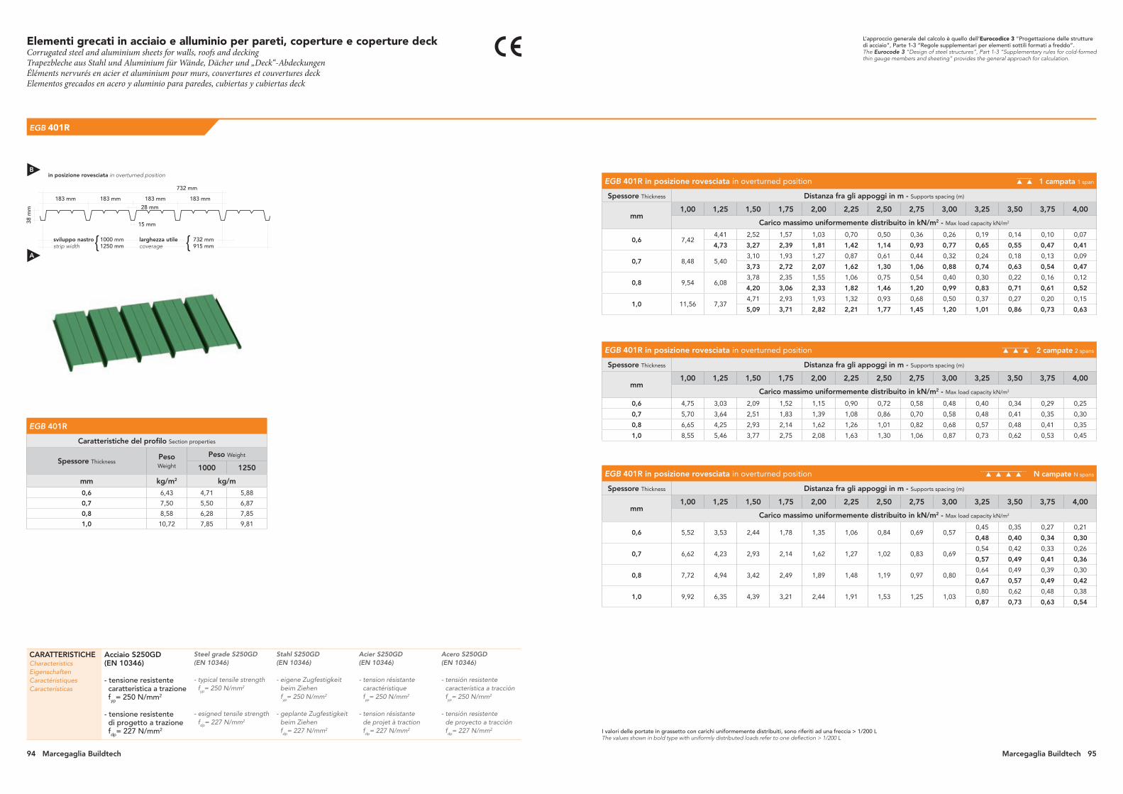
EGB 401R
EGB 401R in posizione rovesciata in overturned position 1 campata 1 span
Spessore Thickness Distanza fra gli appoggi in m - Supports spacing (m)
mm 1,00 1,25 1,50 1,75 2,00 2,25 2,50 2,75 3,00 3,25 3,50 3,75 4,00
Carico massimo uniformemente distribuito in kN/m2 - Max load capacity kN/m2
0,6 7,424,41 2,52 1,57 1,03 0,70 0,50 0,36 0,26 0,19 0,14 0,10 0,07
4,73 3,27 2,39 1,81 1,42 1,14 0,93 0,77 0,65 0,55 0,47 0,41
0,7 8,48 5,403,10 1,93 1,27 0,87 0,61 0,44 0,32 0,24 0,18 0,13 0,09
3,73 2,72 2,07 1,62 1,30 1,06 0,88 0,74 0,63 0,54 0,47
0,8 9,54 6,083,78 2,35 1,55 1,06 0,75 0,54 0,40 0,30 0,22 0,16 0,12
4,20 3,06 2,33 1,82 1,46 1,20 0,99 0,83 0,71 0,61 0,52
1,0 11,56 7,374,71 2,93 1,93 1,32 0,93 0,68 0,50 0,37 0,27 0,20 0,15
5,09 3,71 2,82 2,21 1,77 1,45 1,20 1,01 0,86 0,73 0,63
EGB 401R in posizione rovesciata in overturned position 2 campate 2 spans
Spessore Thickness Distanza fra gli appoggi in m - Supports spacing (m)
mm 1,00 1,25 1,50 1,75 2,00 2,25 2,50 2,75 3,00 3,25 3,50 3,75 4,00
Carico massimo uniformemente distribuito in kN/m2 - Max load capacity kN/m2
0,6 4,75 3,03 2,09 1,52 1,15 0,90 0,72 0,58 0,48 0,40 0,34 0,29 0,25
0,7 5,70 3,64 2,51 1,83 1,39 1,08 0,86 0,70 0,58 0,48 0,41 0,35 0,30
0,8 6,65 4,25 2,93 2,14 1,62 1,26 1,01 0,82 0,68 0,57 0,48 0,41 0,35
1,0 8,55 5,46 3,77 2,75 2,08 1,63 1,30 1,06 0,87 0,73 0,62 0,53 0,45
EGB 401R in posizione rovesciata in overturned position N campate N spans
Spessore Thickness Distanza fra gli appoggi in m - Supports spacing (m)
mm 1,00 1,25 1,50 1,75 2,00 2,25 2,50 2,75 3,00 3,25 3,50 3,75 4,00
Carico massimo uniformemente distribuito in kN/m2 - Max load capacity kN/m2
0,6 5,52 3,53 2,44 1,78 1,35 1,06 0,84 0,69 0,570,45 0,35 0,27 0,21
0,48 0,40 0,34 0,30
0,7 6,62 4,23 2,93 2,14 1,62 1,27 1,02 0,83 0,690,54 0,42 0,33 0,26
0,57 0,49 0,41 0,36
0,8 7,72 4,94 3,42 2,49 1,89 1,48 1,19 0,97 0,800,64 0,49 0,39 0,30
0,67 0,57 0,49 0,42
1,0 9,92 6,35 4,39 3,21 2,44 1,91 1,53 1,25 1,030,80 0,62 0,48 0,38
0,87 0,73 0,63 0,54
CARATTERISTICHECharacteristicsEigenschaftenCaractéristiquesCaracterísticas
Acciaio S250GD (EN 10346)
- tensione resistente caratteristica a trazione fyp= 250 N/mm2
- tensione resistente di progetto a trazione fdp= 227 N/mm2
Steel grade S250GD (EN 10346)
- typical tensile strength fyp= 250 N/mm2
- esigned tensile strength fdp= 227 N/mm2
Stahl S250GD (EN 10346)
- eigene Zugfestigkeit beim Ziehen fyp= 250 N/mm2
- geplante Zugfestigkeit beim Ziehen fdp= 227 N/mm2
Acier S250GD (EN 10346)
- tension résistante caractéristique fyp= 250 N/mm2
- tension résistante de projet à traction fdp= 227 N/mm2
Acero S250GD(EN 10346)
- tensión resistente característica a tracción fyp= 250 N/mm2
- tensión resistente de proyecto a tracción fdp= 227 N/mm2
L’approccio generale del calcolo è quello dell’Eurocodice 3 “Progettazione delle strutture di acciaio”, Parte 1-3 “Regole supplementari per elementi sottili formati a freddo”.The Eurocode 3 “Design of steel structures”, Part 1-3 “Supplementary rules for cold-formed thin gauge members and sheeting” provides the general approach for calculation.
I valori delle portate in grassetto con carichi uniformemente distribuiti, sono riferiti ad una freccia > 1/200 LThe values shown in bold type with uniformly distributed loads refer to one deflection > 1/200 L
EGB 401R
Caratteristiche del profilo Section properties
Spessore Thickness Peso Weight
Peso Weight
1000 1250
mm kg/m2 kg/m
0,6 6,43 4,71 5,88
0,7 7,50 5,50 6,87
0,8 8,58 6,28 7,85
1,0 10,72 7,85 9,81
1000 mm1250 mm
732 mm915 mm
28 mm
38 m
m
732 mm
183 mm 183 mm 183 mm
15 mm
183 mm
sviluppo nastrostrip width
larghezza utilecoverage{ {
in posizione rovesciata in overturned positionB
A
Elementi grecati in acciaio e alluminio per pareti, coperture e coperture deckCorrugated steel and aluminium sheets for walls, roofs and deckingTrapezbleche aus Stahl und Aluminium für Wände, Dächer und „Deck“-Abdeckungen Éléments nervurés en acier et aluminium pour murs, couvertures et couvertures deckElementos grecados en acero y aluminio para paredes, cubiertas y cubiertas deck
94 Marcegaglia Buildtech Marcegaglia Buildtech 95
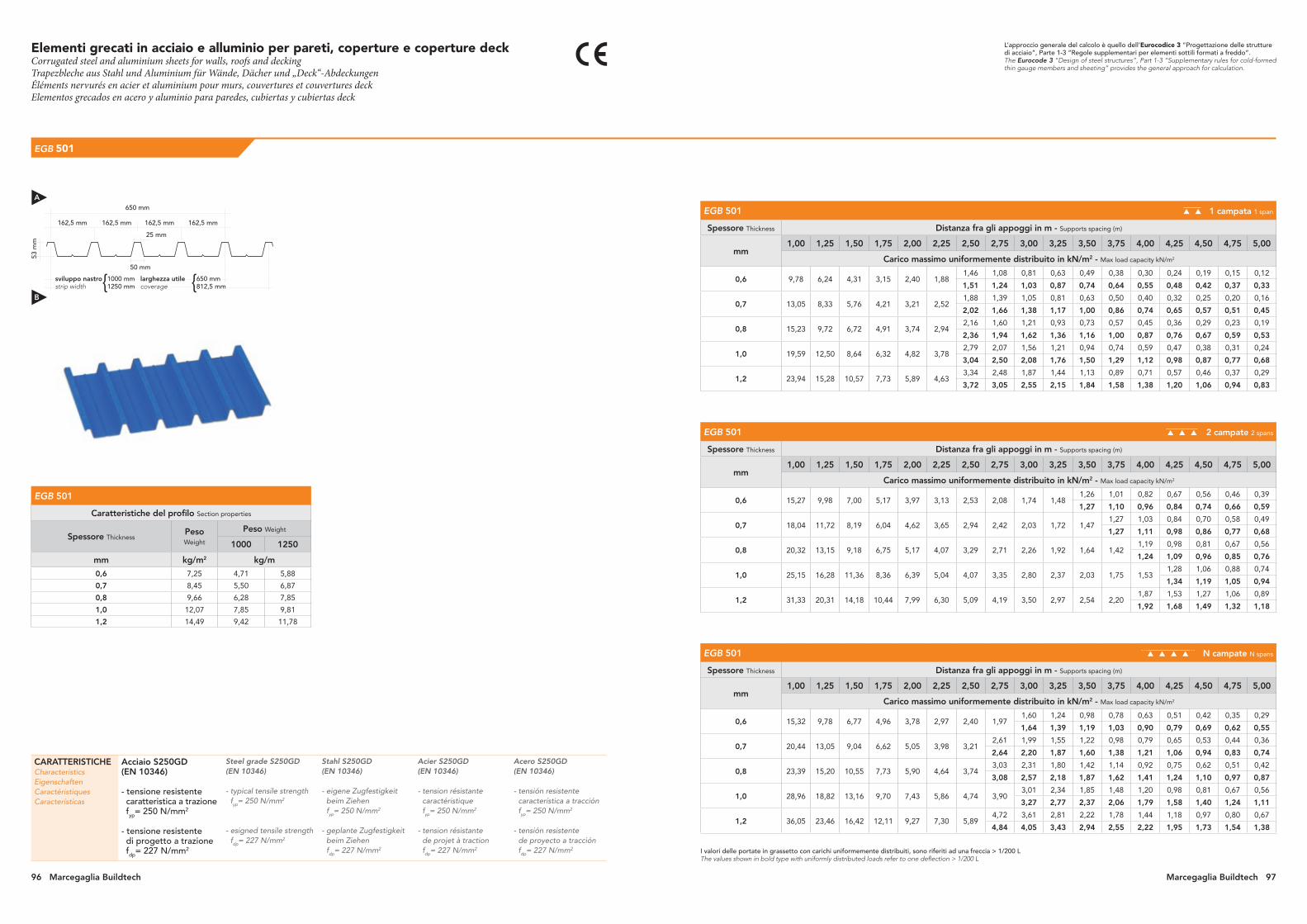
EGB 501
EGB 501 1 campata 1 span
Spessore Thickness Distanza fra gli appoggi in m - Supports spacing (m)
mm 1,00 1,25 1,50 1,75 2,00 2,25 2,50 2,75 3,00 3,25 3,50 3,75 4,00 4,25 4,50 4,75 5,00
Carico massimo uniformemente distribuito in kN/m2 - Max load capacity kN/m2
0,6 9,78 6,24 4,31 3,15 2,40 1,881,46 1,08 0,81 0,63 0,49 0,38 0,30 0,24 0,19 0,15 0,12
1,51 1,24 1,03 0,87 0,74 0,64 0,55 0,48 0,42 0,37 0,33
0,7 13,05 8,33 5,76 4,21 3,21 2,521,88 1,39 1,05 0,81 0,63 0,50 0,40 0,32 0,25 0,20 0,16
2,02 1,66 1,38 1,17 1,00 0,86 0,74 0,65 0,57 0,51 0,45
0,8 15,23 9,72 6,72 4,91 3,74 2,942,16 1,60 1,21 0,93 0,73 0,57 0,45 0,36 0,29 0,23 0,19
2,36 1,94 1,62 1,36 1,16 1,00 0,87 0,76 0,67 0,59 0,53
1,0 19,59 12,50 8,64 6,32 4,82 3,782,79 2,07 1,56 1,21 0,94 0,74 0,59 0,47 0,38 0,31 0,24
3,04 2,50 2,08 1,76 1,50 1,29 1,12 0,98 0,87 0,77 0,68
1,2 23,94 15,28 10,57 7,73 5,89 4,633,34 2,48 1,87 1,44 1,13 0,89 0,71 0,57 0,46 0,37 0,29
3,72 3,05 2,55 2,15 1,84 1,58 1,38 1,20 1,06 0,94 0,83
EGB 501 2 campate 2 spans
Spessore Thickness Distanza fra gli appoggi in m - Supports spacing (m)
mm 1,00 1,25 1,50 1,75 2,00 2,25 2,50 2,75 3,00 3,25 3,50 3,75 4,00 4,25 4,50 4,75 5,00
Carico massimo uniformemente distribuito in kN/m2 - Max load capacity kN/m2
0,6 15,27 9,98 7,00 5,17 3,97 3,13 2,53 2,08 1,74 1,481,26 1,01 0,82 0,67 0,56 0,46 0,39
1,27 1,10 0,96 0,84 0,74 0,66 0,59
0,7 18,04 11,72 8,19 6,04 4,62 3,65 2,94 2,42 2,03 1,72 1,471,27 1,03 0,84 0,70 0,58 0,49
1,27 1,11 0,98 0,86 0,77 0,68
0,8 20,32 13,15 9,18 6,75 5,17 4,07 3,29 2,71 2,26 1,92 1,64 1,421,19 0,98 0,81 0,67 0,56
1,24 1,09 0,96 0,85 0,76
1,0 25,15 16,28 11,36 8,36 6,39 5,04 4,07 3,35 2,80 2,37 2,03 1,75 1,531,28 1,06 0,88 0,74
1,34 1,19 1,05 0,94
1,2 31,33 20,31 14,18 10,44 7,99 6,30 5,09 4,19 3,50 2,97 2,54 2,201,87 1,53 1,27 1,06 0,89
1,92 1,68 1,49 1,32 1,18
EGB 501 N campate N spans
Spessore Thickness Distanza fra gli appoggi in m - Supports spacing (m)
mm 1,00 1,25 1,50 1,75 2,00 2,25 2,50 2,75 3,00 3,25 3,50 3,75 4,00 4,25 4,50 4,75 5,00
Carico massimo uniformemente distribuito in kN/m2 - Max load capacity kN/m2
0,6 15,32 9,78 6,77 4,96 3,78 2,97 2,40 1,971,60 1,24 0,98 0,78 0,63 0,51 0,42 0,35 0,29
1,64 1,39 1,19 1,03 0,90 0,79 0,69 0,62 0,55
0,7 20,44 13,05 9,04 6,62 5,05 3,98 3,212,61 1,99 1,55 1,22 0,98 0,79 0,65 0,53 0,44 0,36
2,64 2,20 1,87 1,60 1,38 1,21 1,06 0,94 0,83 0,74
0,8 23,39 15,20 10,55 7,73 5,90 4,64 3,743,03 2,31 1,80 1,42 1,14 0,92 0,75 0,62 0,51 0,42
3,08 2,57 2,18 1,87 1,62 1,41 1,24 1,10 0,97 0,87
1,0 28,96 18,82 13,16 9,70 7,43 5,86 4,74 3,903,01 2,34 1,85 1,48 1,20 0,98 0,81 0,67 0,56
3,27 2,77 2,37 2,06 1,79 1,58 1,40 1,24 1,11
1,2 36,05 23,46 16,42 12,11 9,27 7,30 5,894,72 3,61 2,81 2,22 1,78 1,44 1,18 0,97 0,80 0,67
4,84 4,05 3,43 2,94 2,55 2,22 1,95 1,73 1,54 1,38
CARATTERISTICHECharacteristicsEigenschaftenCaractéristiquesCaracterísticas
Acciaio S250GD (EN 10346)
- tensione resistente caratteristica a trazione fyp= 250 N/mm2
- tensione resistente di progetto a trazione fdp= 227 N/mm2
Steel grade S250GD (EN 10346)
- typical tensile strength fyp= 250 N/mm2
- esigned tensile strength fdp= 227 N/mm2
Stahl S250GD (EN 10346)
- eigene Zugfestigkeit beim Ziehen fyp= 250 N/mm2
- geplante Zugfestigkeit beim Ziehen fdp= 227 N/mm2
Acier S250GD (EN 10346)
- tension résistante caractéristique fyp= 250 N/mm2
- tension résistante de projet à traction fdp= 227 N/mm2
Acero S250GD(EN 10346)
- tensión resistente característica a tracción fyp= 250 N/mm2
- tensión resistente de proyecto a tracción fdp= 227 N/mm2
L’approccio generale del calcolo è quello dell’Eurocodice 3 “Progettazione delle strutture di acciaio”, Parte 1-3 “Regole supplementari per elementi sottili formati a freddo”.The Eurocode 3 “Design of steel structures”, Part 1-3 “Supplementary rules for cold-formed thin gauge members and sheeting” provides the general approach for calculation.
I valori delle portate in grassetto con carichi uniformemente distribuiti, sono riferiti ad una freccia > 1/200 LThe values shown in bold type with uniformly distributed loads refer to one deflection > 1/200 L
EGB 501
Caratteristiche del profilo Section properties
Spessore Thickness Peso Weight
Peso Weight
1000 1250
mm kg/m2 kg/m
0,6 7,25 4,71 5,88
0,7 8,45 5,50 6,87
0,8 9,66 6,28 7,85
1,0 12,07 7,85 9,81
1,2 14,49 9,42 11,78
1000 mm1250 mm
650 mm812,5 mm
53 m
m
650 mm
162,5 mm 162,5 mm 162,5 mm
25 mm
50 mm
162,5 mm
sviluppo nastrostrip width
larghezza utilecoverage{ {
A
B
Elementi grecati in acciaio e alluminio per pareti, coperture e coperture deckCorrugated steel and aluminium sheets for walls, roofs and deckingTrapezbleche aus Stahl und Aluminium für Wände, Dächer und „Deck“-Abdeckungen Éléments nervurés en acier et aluminium pour murs, couvertures et couvertures deckElementos grecados en acero y aluminio para paredes, cubiertas y cubiertas deck
96 Marcegaglia Buildtech Marcegaglia Buildtech 97

EGB 501R
EGB 501R 1 campata 1 span
Spessore Thickness Distanza fra gli appoggi in m - Supports spacing (m)
mm 1,00 1,25 1,50 1,75 2,00 2,25 2,50 2,75 3,00 3,25 3,50 3,75 4,00 4,25 4,50 4,75 5,00
Carico massimo uniformemente distribuito in kN/m2 - Max load capacity kN/m2
0,6 16,35 10,446,87 4,30 2,85 1,98 1,43 1,05 0,80 0,61 0,47 0,37 0,29 0,23 0,18 0,15 0,12
7,23 5,29 4,04 3,18 2,56 2,11 1,76 1,49 1,27 1,10 0,96 0,84 0,75 0,66 0,59
0,7 18,96 12,118,30 5,19 3,45 2,40 1,73 1,28 0,96 0,74 0,58 0,45 0,36 0,28 0,23 0,18 0,14
8,38 6,14 4,68 3,68 2,97 2,44 2,04 1,73 1,48 1,28 1,11 0,98 0,86 0,77 0,69
0,8 21,14 13,50 9,356,09 4,05 2,81 2,03 1,50 1,13 0,87 0,68 0,53 0,42 0,34 0,27 0,21 0,17
6,84 5,22 4,11 3,31 2,72 2,27 1,92 1,65 1,42 1,24 1,09 0,96 0,85 0,76
1,0 26,15 16,70 11,567,96 5,30 3,68 2,65 1,96 1,49 1,14 0,89 0,70 0,56 0,45 0,36 0,29 0,23
8,47 6,46 5,08 4,09 3,36 2,81 2,38 2,04 1,76 1,53 1,35 1,19 1,06 0,94
1,2 32,69 20,88 14,469,56 6,36 4,42 3,18 2,36 1,78 1,37 1,07 0,84 0,67 0,53 0,43 0,34 0,27
10,59 8,08 6,35 5,12 4,21 3,52 2,98 2,55 2,21 1,92 1,69 1,49 1,33 1,18
EGB 501R 2 campate 2 spans
Spessore Thickness Distanza fra gli appoggi in m - Supports spacing (m)
mm 1,00 1,25 1,50 1,75 2,00 2,25 2,50 2,75 3,00 3,25 3,50 3,75 4,00 4,25 4,50 4,75 5,00
Carico massimo uniformemente distribuito in kN/m2 - Max load capacity kN/m2
0,6 9,53 6,13 4,26 3,12 2,38 1,87 1,50 1,23 1,03 0,86 0,74 0,63 0,55 0,48 0,42 0,37 0,33
0,7 12,74 8,20 5,70 4,18 3,19 2,50 2,02 1,65 1,38 1,16 0,99 0,86 0,74 0,65 0,57 0,51 0,45
0,8 14,91 9,58 6,66 4,88 3,72 2,93 2,36 1,93 1,61 1,36 1,16 1,00 0,87 0,76 0,67 0,59 0,53
1,0 19,15 12,32 8,56 6,28 4,79 3,77 3,03 2,49 2,08 1,75 1,50 1,29 1,12 0,98 0,86 0,76 0,68
1,2 23,39 15,05 10,46 7,67 5,85 4,60 3,71 3,04 2,54 2,15 1,83 1,58 1,37 1,20 1,06 0,94 0,83
EGB 501R N campate N spans
Spessore Thickness Distanza fra gli appoggi in m - Supports spacing (m)
mm 1,00 1,25 1,50 1,75 2,00 2,25 2,50 2,75 3,00 3,25 3,50 3,75 4,00 4,25 4,50 4,75 5,00
Carico massimo uniformemente distribuito in kN/m2 - Max load capacity kN/m2
0,6 11,02 7,11 4,95 3,63 2,77 2,18 1,76 1,44 1,20 1,02 0,87 0,750,63 0,51 0,42 0,35 0,29
0,65 0,57 0,50 0,44 0,39
0,7 14,72 9,50 6,61 4,86 3,71 2,92 2,35 1,93 1,61 1,36 1,170,98 0,79 0,65 0,53 0,44 0,36
1,01 0,88 0,77 0,68 0,60 0,53
0,8 17,25 11,12 7,73 5,68 4,33 3,41 2,75 2,26 1,89 1,59 1,361,14 0,92 0,75 0,62 0,51 0,42
1,18 1,02 0,90 0,79 0,70 0,63
1,0 22,15 14,28 9,94 7,30 5,57 4,39 3,54 2,91 2,43 2,05 1,761,48 1,20 0,98 0,81 0,67 0,56
1,52 1,32 1,16 1,02 0,91 0,81
1,2 27,04 17,44 12,14 8,92 6,81 5,37 4,33 3,56 2,97 2,51 2,151,78 1,44 1,18 0,97 0,80 0,67
1,86 1,62 1,42 1,25 1,11 0,99CARATTERISTICHECharacteristicsEigenschaftenCaractéristiquesCaracterísticas
Acciaio S250GD (EN 10346)
- tensione resistente caratteristica a trazione fyp= 250 N/mm2
- tensione resistente di progetto a trazione fdp= 227 N/mm2
Steel grade S250GD (EN 10346)
- typical tensile strength fyp= 250 N/mm2
- esigned tensile strength fdp= 227 N/mm2
Stahl S250GD (EN 10346)
- eigene Zugfestigkeit beim Ziehen fyp= 250 N/mm2
- geplante Zugfestigkeit beim Ziehen fdp= 227 N/mm2
Acier S250GD (EN 10346)
- tension résistante caractéristique fyp= 250 N/mm2
- tension résistante de projet à traction fdp= 227 N/mm2
Acero S250GD(EN 10346)
- tensión resistente característica a tracción fyp= 250 N/mm2
- tensión resistente de proyecto a tracción fdp= 227 N/mm2
L’approccio generale del calcolo è quello dell’Eurocodice 3 “Progettazione delle strutture di acciaio”, Parte 1-3 “Regole supplementari per elementi sottili formati a freddo”.The Eurocode 3 “Design of steel structures”, Part 1-3 “Supplementary rules for cold-formed thin gauge members and sheeting” provides the general approach for calculation.
I valori delle portate in grassetto con carichi uniformemente distribuiti, sono riferiti ad una freccia > 1/200 LThe values shown in bold type with uniformly distributed loads refer to one deflection > 1/200 L
EGB 501R
Caratteristiche del profilo Section properties
Spessore Thickness Peso Weight
Peso Weight
1000 1250
mm kg/m2 kg/m
0,6 7,25 4,71 5,88
0,7 8,45 5,50 6,87
0,8 9,66 6,28 7,85
1,0 12,07 7,85 9,81
1,2 14,49 9,42 11,78
1000 mm1250 mm
650 mm812,5 mm
53 m
m
650 mm
162,5 mm 162,5 mm 162,5 mm
25 mm
50 mm
162,5 mm
sviluppo nastrostrip width
larghezza utilecoverage{ {
in posizione rovesciata in overturned positionB
A
Elementi grecati in acciaio e alluminio per pareti, coperture e coperture deckCorrugated steel and aluminium sheets for walls, roofs and deckingTrapezbleche aus Stahl und Aluminium für Wände, Dächer und „Deck“-Abdeckungen Éléments nervurés en acier et aluminium pour murs, couvertures et couvertures deckElementos grecados en acero y aluminio para paredes, cubiertas y cubiertas deck
98 Marcegaglia Buildtech Marcegaglia Buildtech 99

Elementi grecati in acciaio e alluminio per pareti e soffittatureCorrugated steel and aluminium sheets for walls and false ceilingsTrapezbleche aus Stahl und Aluminium für Wände und DeckenÉléments nervurés en acier et aluminium pour murs et plafondsElementos grecados en acero y aluminio para paredes y techos
EGB 902
CARATTERISTICHECharacteristicsEigenschaftenCaractéristiquesCaracterísticas
Acciaio S250GD (EN 10346)
- tensione resistente caratteristica a trazione fyp= 250 N/mm2
- tensione resistente di progetto a trazione fdp= 227 N/mm2
Steel grade S250GD (EN 10346)
- typical tensile strength fyp= 250 N/mm2
- esigned tensile strength fdp= 227 N/mm2
Stahl S250GD (EN 10346)
- eigene Zugfestigkeit beim Ziehen fyp= 250 N/mm2
- geplante Zugfestigkeit beim Ziehen fdp= 227 N/mm2
Acier S250GD (EN 10346)
- tension résistante caractéristique fyp= 250 N/mm2
- tension résistante de projet à traction fdp= 227 N/mm2
Acero S250GD(EN 10346)
- tensión resistente característica a tracción fyp= 250 N/mm2
- tensión resistente de proyecto a tracción fdp= 227 N/mm2
L’approccio generale del calcolo è quello dell’Eurocodice 3 “Progettazione delle strutture di acciaio”, Parte 1-3 “Regole supplementari per elementi sottili formati a freddo”.The Eurocode 3 “Design of steel structures”, Part 1-3 “Supplementary rules for cold-formed thin gauge members and sheeting” provides the general approach for calculation.
I valori delle portate in grassetto con carichi uniformemente distribuiti, sono riferiti ad una freccia > 1/200 LThe values shown in bold type with uniformly distributed loads refer to one deflection > 1/200 L
EGB 902
Caratteristiche del profilo Section properties
Spessore Thickness Peso Weight
Peso Weight
1000 1250
mm kg/m2 kg/m
0,6 5,61 4,71 5,88
0,7 6,54 5,50 6,87
0,8 7,48 6,28 7,85
1,0 9,35 7,85 9,81
sviluppo nastro strip width 1000 mm
sviluppo nastro strip width 1250 mm
35 m
m35
mm
840 mm
210 mm 60 mm
210 mm
1050 mm
60 mm
EGB 902 1 campata 1 span
Spessore Thickness Distanza fra gli appoggi in m - Supports spacing (m)
mm 1,00 1,25 1,50 1,75 2,00 2,25 2,50 2,75 3,00 3,25 3,50 3,75 4,00
Carico massimo uniformemente distribuito in kN/m2 - Max load capacity kN/m2
0,6 5,86 3,732,29 1,43 0,94 0,64 0,45 0,33 0,24 0,18 0,13 0,10 0,07
2,58 1,88 1,43 1,12 0,90 0,73 0,61 0,51 0,43 0,37 0,32
0,7 7,54 4,812,85 1,77 1,17 0,80 0,57 0,41 0,30 0,22 0,17 0,12 0,09
3,32 2,42 1,84 1,44 1,16 0,95 0,79 0,66 0,56 0,48 0,42
0,8 8,38 5,343,35 2,09 1,37 0,94 0,67 0,49 0,36 0,27 0,20 0,15 0,11
3,69 2,69 2,05 1,60 1,29 1,05 0,87 0,74 0,63 0,54 0,46
1,0 11,74 7,484,45 2,77 1,83 1,26 0,89 0,65 0,48 0,36 0,27 0,20 0,15
5,17 3,78 2,87 2,25 1,81 1,48 1,23 1,04 0,89 0,76 0,66
EGB 902 2 campate 2 spans
Spessore Thickness Distanza fra gli appoggi in m - Supports spacing (m)
mm 1,00 1,25 1,50 1,75 2,00 2,25 2,50 2,75 3,00 3,25 3,50 3,75 4,00
Carico massimo uniformemente distribuito in kN/m2 - Max load capacity kN/m2
0,6 5,77 3,70 2,56 1,87 1,42 1,12 0,90 0,73 0,610,51 0,40 0,31 0,25
0,51 0,43 0,37 0,32
0,7 7,44 4,76 3,30 2,41 1,84 1,44 1,16 0,95 0,790,64 0,50 0,39 0,31
0,66 0,56 0,48 0,42
0,8 9,11 5,83 4,04 2,96 2,25 1,77 1,42 1,16 0,970,76 0,59 0,47 0,37
0,81 0,69 0,60 0,52
1,0 12,41 7,95 5,51 4,04 3,07 2,41 1,94 1,591,30 1,01 0,79 0,62 0,50
1,33 1,12 0,95 0,82 0,71
EGB 902 N campate N spans
Spessore Thickness Distanza fra gli appoggi in m - Supports spacing (m)
mm 1,00 1,25 1,50 1,75 2,00 2,25 2,50 2,75 3,00 3,25 3,50 3,75 4,00
Carico massimo uniformemente distribuito in kN/m2 - Max load capacity kN/m2
0,6 6,69 4,29 2,98 2,18 1,661,28 0,92 0,68 0,51 0,39 0,30 0,24 0,18
1,30 1,05 0,86 0,71 0,60 0,51 0,44 0,38
0,7 8,62 5,53 3,84 2,81 2,141,60 1,15 0,85 0,64 0,49 0,38 0,30 0,23
1,68 1,35 1,11 0,92 0,78 0,66 0,57 0,50
0,8 10,56 6,77 4,70 3,44 2,621,89 1,36 1,00 0,76 0,58 0,45 0,35 0,28
2,06 1,66 1,36 1,13 0,96 0,82 0,70 0,61
1,0 14,39 9,24 6,41 4,70 3,582,51 1,80 1,33 1,01 0,77 0,60 0,47 0,37
2,82 2,27 1,86 1,55 1,31 1,12 0,97 0,84
A
A
B
B
100 Marcegaglia Buildtech Marcegaglia Buildtech 101
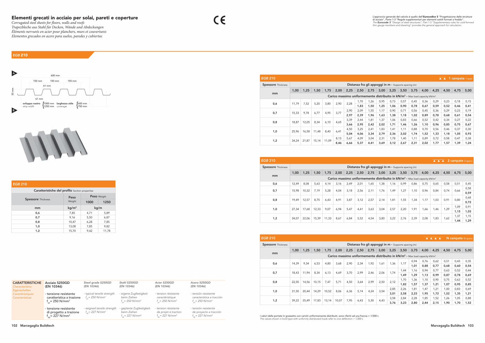
larghezza utilecoverage
Elementi grecati in acciaio per solai, pareti e copertureCorrugated steel sheets for floors, walls and roofsTrapezbleche aus Stahl für Decken, Wände und AbdeckungenÉléments nervurés en acier pour planchers, murs et couverturesElementos grecados en acero para suelos, paredes y cubiertas
EGB 210
CARATTERISTICHECharacteristicsEigenschaftenCaractéristiquesCaracterísticas
Acciaio S250GD (EN 10346)
- tensione resistente caratteristica a trazione fyp= 250 N/mm2
- tensione resistente di progetto a trazione fdp= 227 N/mm2
Steel grade S250GD (EN 10346)
- typical tensile strength fyp= 250 N/mm2
- esigned tensile strength fdp= 227 N/mm2
Stahl S250GD (EN 10346)
- eigene Zugfestigkeit beim Ziehen fyp= 250 N/mm2
- geplante Zugfestigkeit beim Ziehen fdp= 227 N/mm2
Acier S250GD (EN 10346)
- tension résistante caractéristique fyp= 250 N/mm2
- tension résistante de projet à traction fdp= 227 N/mm2
Acero S250GD(EN 10346)
- tensión resistente característica a tracción fyp= 250 N/mm2
- tensión resistente de proyecto a tracción fdp= 227 N/mm2
L’approccio generale del calcolo è quello dell’Eurocodice 3 “Progettazione delle strutture di acciaio”, Parte 1-3 “Regole supplementari per elementi sottili formati a freddo”.The Eurocode 3 “Design of steel structures”, Part 1-3 “Supplementary rules for cold-formed thin gauge members and sheeting” provides the general approach for calculation.
I valori delle portate in grassetto con carichi uniformemente distribuiti, sono riferiti ad una freccia > 1/200 LThe values shown in bold type with uniformly distributed loads refer to one deflection > 1/200 L
EGB 210 1 campata 1 span
Spessore Thickness Distanza fra gli appoggi in m - Supports spacing (m)
mm 1,00 1,25 1,50 1,75 2,00 2,25 2,50 2,75 3,00 3,25 3,50 3,75 4,00 4,25 4,50 4,75 5,00
Carico massimo uniformemente distribuito in kN/m2 - Max load capacity kN/m2
0,6 11,79 7,52 5,20 3,80 2,90 2,281,70 1,26 0,95 0,73 0,57 0,45 0,36 0,29 0,23 0,18 0,15
1,83 1,50 1,25 1,06 0,90 0,78 0,67 0,59 0,52 0,46 0,41
0,7 15,33 9,78 6,77 4,95 3,772,90 2,09 1,55 1,17 0,90 0,71 0,56 0,45 0,36 0,29 0,23 0,19
2,97 2,39 1,96 1,63 1,38 1,18 1,02 0,89 0,78 0,68 0,61 0,54
0,8 18,87 12,05 8,34 6,10 4,653,39 2,44 1,81 1,37 1,06 0,83 0,66 0,52 0,42 0,34 0,27 0,22
3,66 2,95 2,42 2,02 1,71 1,46 1,26 1,10 0,96 0,85 0,75 0,67
1,0 25,96 16,58 11,48 8,40 6,414,50 3,25 2,41 1,83 1,41 1,11 0,88 0,70 0,56 0,46 0,37 0,30
5,04 4,06 3,34 2,79 2,36 2,02 1,74 1,52 1,33 1,18 1,05 0,93
1,2 34,24 21,87 15,14 11,098,13 5,67 4,09 3,04 2,31 1,78 1,40 1,11 0,89 0,72 0,58 0,47 0,38
8,46 6,66 5,37 4,41 3,69 3,12 2,67 2,31 2,02 1,77 1,57 1,39 1,24
EGB 210 2 campate 2 spans
Spessore Thickness Distanza fra gli appoggi in m - Supports spacing (m)
mm 1,00 1,25 1,50 1,75 2,00 2,25 2,50 2,75 3,00 3,25 3,50 3,75 4,00 4,25 4,50 4,75 5,00
Carico massimo uniformemente distribuito in kN/m2 - Max load capacity kN/m2
0,6 12,49 8,08 5,63 4,14 3,16 2,49 2,01 1,65 1,38 1,16 0,99 0,86 0,75 0,65 0,58 0,51 0,45
0,7 15,98 10,32 7,19 5,28 4,04 3,18 2,56 2,11 1,76 1,49 1,27 1,10 0,96 0,84 0,74 0,660,58
0,59
0,8 19,49 12,57 8,75 6,43 4,91 3,87 3,12 2,57 2,14 1,81 1,55 1,34 1,17 1,03 0,91 0,800,68
0,72
1,0 27,34 17,68 12,33 9,07 6,94 5,47 4,41 3,63 3,04 2,57 2,20 1,91 1,66 1,46 1,291,09 0,91
1,15 1,03
1,2 34,07 22,06 15,39 11,33 8,67 6,84 5,52 4,54 3,80 3,22 2,76 2,39 2,08 1,83 1,621,37 1,15
1,44 1,29
EGB 210 N campate N spans
Spessore Thickness Distanza fra gli appoggi in m - Supports spacing (m)
mm 1,00 1,25 1,50 1,75 2,00 2,25 2,50 2,75 3,00 3,25 3,50 3,75 4,00 4,25 4,50 4,75 5,00
Carico massimo uniformemente distribuito in kN/m2 - Max load capacity kN/m2
0,6 14,39 9,34 6,53 4,80 3,68 2,90 2,34 1,92 1,61 1,36 1,170,94 0,76 0,62 0,51 0,43 0,35
1,01 0,88 0,77 0,68 0,60 0,54
0,7 18,43 11,94 8,34 6,13 4,69 3,70 2,99 2,46 2,06 1,741,44 1,16 0,94 0,77 0,63 0,52 0,44
1,49 1,29 1,13 0,99 0,87 0,78 0,69
0,8 22,50 14,56 10,15 7,47 5,71 4,50 3,64 2,99 2,50 2,121,70 1,36 1,10 0,90 0,75 0,62 0,52
1,82 1,57 1,37 1,21 1,07 0,95 0,85
1,0 31,50 20,44 14,29 10,52 8,06 6,36 5,14 4,24 3,542,85 2,26 1,81 1,47 1,21 1,00 0,83 0,69
3,01 2,58 2,23 1,95 1,72 1,52 1,35 1,21
1,2 39,22 25,49 17,83 13,14 10,07 7,95 6,43 5,30 4,433,58 2,84 2,28 1,85 1,52 1,26 1,05 0,88
3,76 3,23 2,80 2,44 2,15 1,90 1,70 1,52
1000 mm1250 mm
600 mm750 mm
55 m
m
600 mm
150 mm150 mm150 mm
61 mm
61 mm
sviluppo nastrostrip width { {
EGB 210
Caratteristiche del profilo Section properties
Spessore Thickness Peso Weight
Peso Weight
1000 1250
mm kg/m2 kg/m
0,6 7,85 4,71 5,89
0,7 9,16 5,50 6,87
0,8 10,47 6,28 7,85
1,0 13,08 7,85 9,82
1,2 15,70 9,42 11,78
A
B
102 Marcegaglia Buildtech Marcegaglia Buildtech 103
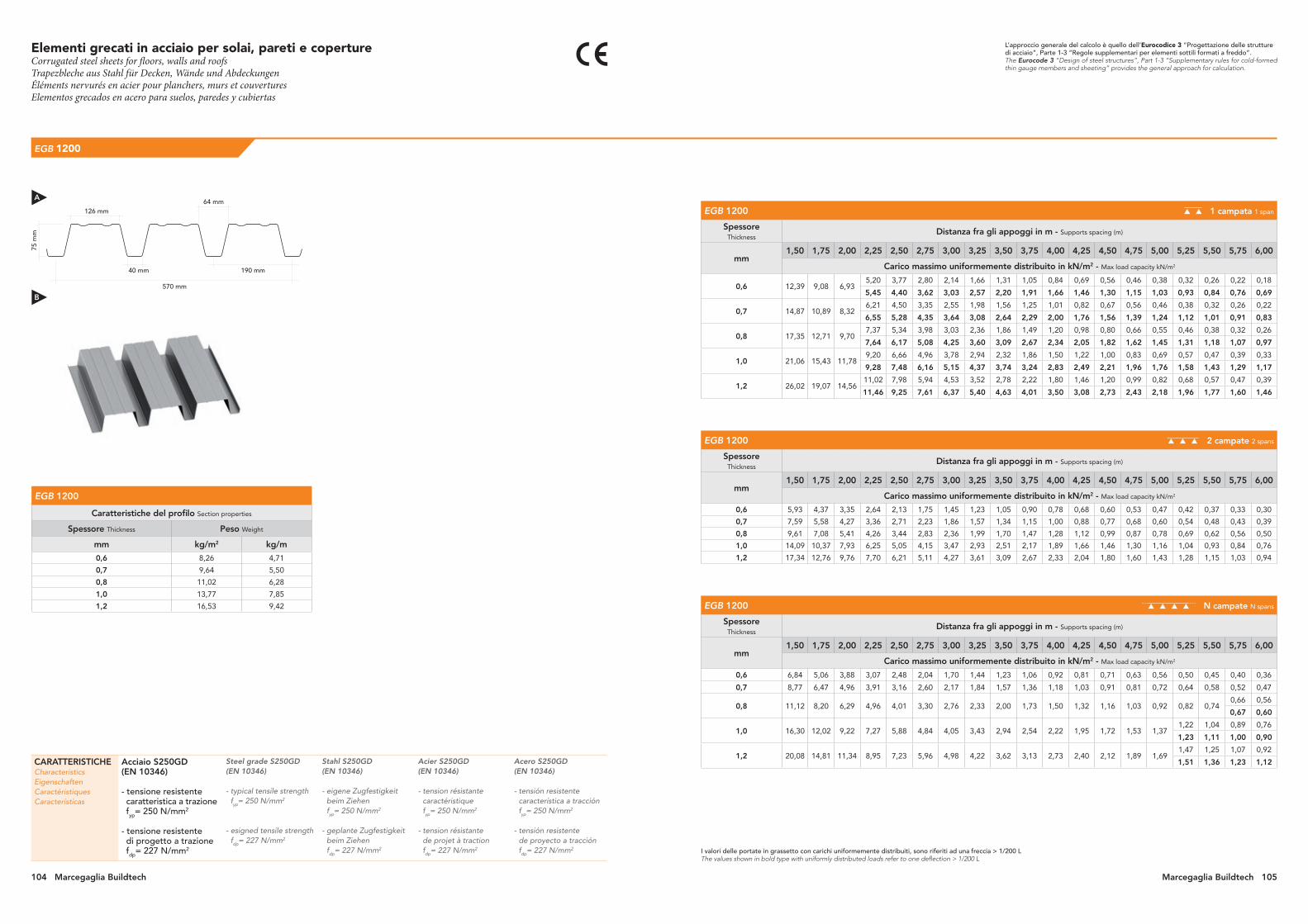
EGB 1200
CARATTERISTICHECharacteristicsEigenschaftenCaractéristiquesCaracterísticas
Acciaio S250GD (EN 10346)
- tensione resistente caratteristica a trazione fyp= 250 N/mm2
- tensione resistente di progetto a trazione fdp= 227 N/mm2
Steel grade S250GD (EN 10346)
- typical tensile strength fyp= 250 N/mm2
- esigned tensile strength fdp= 227 N/mm2
Stahl S250GD (EN 10346)
- eigene Zugfestigkeit beim Ziehen fyp= 250 N/mm2
- geplante Zugfestigkeit beim Ziehen fdp= 227 N/mm2
Acier S250GD (EN 10346)
- tension résistante caractéristique fyp= 250 N/mm2
- tension résistante de projet à traction fdp= 227 N/mm2
Acero S250GD(EN 10346)
- tensión resistente característica a tracción fyp= 250 N/mm2
- tensión resistente de proyecto a tracción fdp= 227 N/mm2
L’approccio generale del calcolo è quello dell’Eurocodice 3 “Progettazione delle strutture di acciaio”, Parte 1-3 “Regole supplementari per elementi sottili formati a freddo”.The Eurocode 3 “Design of steel structures”, Part 1-3 “Supplementary rules for cold-formed thin gauge members and sheeting” provides the general approach for calculation.
I valori delle portate in grassetto con carichi uniformemente distribuiti, sono riferiti ad una freccia > 1/200 LThe values shown in bold type with uniformly distributed loads refer to one deflection > 1/200 L
EGB 1200 1 campata 1 span
Spessore Thickness
Distanza fra gli appoggi in m - Supports spacing (m)
mm 1,50 1,75 2,00 2,25 2,50 2,75 3,00 3,25 3,50 3,75 4,00 4,25 4,50 4,75 5,00 5,25 5,50 5,75 6,00
Carico massimo uniformemente distribuito in kN/m2 - Max load capacity kN/m2
0,6 12,39 9,08 6,935,20 3,77 2,80 2,14 1,66 1,31 1,05 0,84 0,69 0,56 0,46 0,38 0,32 0,26 0,22 0,18
5,45 4,40 3,62 3,03 2,57 2,20 1,91 1,66 1,46 1,30 1,15 1,03 0,93 0,84 0,76 0,69
0,7 14,87 10,89 8,326,21 4,50 3,35 2,55 1,98 1,56 1,25 1,01 0,82 0,67 0,56 0,46 0,38 0,32 0,26 0,22
6,55 5,28 4,35 3,64 3,08 2,64 2,29 2,00 1,76 1,56 1,39 1,24 1,12 1,01 0,91 0,83
0,8 17,35 12,71 9,707,37 5,34 3,98 3,03 2,36 1,86 1,49 1,20 0,98 0,80 0,66 0,55 0,46 0,38 0,32 0,26
7,64 6,17 5,08 4,25 3,60 3,09 2,67 2,34 2,05 1,82 1,62 1,45 1,31 1,18 1,07 0,97
1,0 21,06 15,43 11,789,20 6,66 4,96 3,78 2,94 2,32 1,86 1,50 1,22 1,00 0,83 0,69 0,57 0,47 0,39 0,33
9,28 7,48 6,16 5,15 4,37 3,74 3,24 2,83 2,49 2,21 1,96 1,76 1,58 1,43 1,29 1,17
1,2 26,02 19,07 14,5611,02 7,98 5,94 4,53 3,52 2,78 2,22 1,80 1,46 1,20 0,99 0,82 0,68 0,57 0,47 0,39
11,46 9,25 7,61 6,37 5,40 4,63 4,01 3,50 3,08 2,73 2,43 2,18 1,96 1,77 1,60 1,46
EGB 1200 2 campate 2 spans
Spessore Thickness
Distanza fra gli appoggi in m - Supports spacing (m)
mm 1,50 1,75 2,00 2,25 2,50 2,75 3,00 3,25 3,50 3,75 4,00 4,25 4,50 4,75 5,00 5,25 5,50 5,75 6,00
Carico massimo uniformemente distribuito in kN/m2 - Max load capacity kN/m2
0,6 5,93 4,37 3,35 2,64 2,13 1,75 1,45 1,23 1,05 0,90 0,78 0,68 0,60 0,53 0,47 0,42 0,37 0,33 0,30
0,7 7,59 5,58 4,27 3,36 2,71 2,23 1,86 1,57 1,34 1,15 1,00 0,88 0,77 0,68 0,60 0,54 0,48 0,43 0,39
0,8 9,61 7,08 5,41 4,26 3,44 2,83 2,36 1,99 1,70 1,47 1,28 1,12 0,99 0,87 0,78 0,69 0,62 0,56 0,50
1,0 14,09 10,37 7,93 6,25 5,05 4,15 3,47 2,93 2,51 2,17 1,89 1,66 1,46 1,30 1,16 1,04 0,93 0,84 0,76
1,2 17,34 12,76 9,76 7,70 6,21 5,11 4,27 3,61 3,09 2,67 2,33 2,04 1,80 1,60 1,43 1,28 1,15 1,03 0,94
EGB 1200 N campate N spans
Spessore Thickness
Distanza fra gli appoggi in m - Supports spacing (m)
mm 1,50 1,75 2,00 2,25 2,50 2,75 3,00 3,25 3,50 3,75 4,00 4,25 4,50 4,75 5,00 5,25 5,50 5,75 6,00
Carico massimo uniformemente distribuito in kN/m2 - Max load capacity kN/m2
0,6 6,84 5,06 3,88 3,07 2,48 2,04 1,70 1,44 1,23 1,06 0,92 0,81 0,71 0,63 0,56 0,50 0,45 0,40 0,36
0,7 8,77 6,47 4,96 3,91 3,16 2,60 2,17 1,84 1,57 1,36 1,18 1,03 0,91 0,81 0,72 0,64 0,58 0,52 0,47
0,8 11,12 8,20 6,29 4,96 4,01 3,30 2,76 2,33 2,00 1,73 1,50 1,32 1,16 1,03 0,92 0,82 0,740,66 0,56
0,67 0,60
1,0 16,30 12,02 9,22 7,27 5,88 4,84 4,05 3,43 2,94 2,54 2,22 1,95 1,72 1,53 1,371,22 1,04 0,89 0,76
1,23 1,11 1,00 0,90
1,2 20,08 14,81 11,34 8,95 7,23 5,96 4,98 4,22 3,62 3,13 2,73 2,40 2,12 1,89 1,691,47 1,25 1,07 0,92
1,51 1,36 1,23 1,12
75 m
m
126 mm
40 mm 190 mm
570 mm
EGB 1200
Caratteristiche del profilo Section properties
Spessore Thickness Peso Weight
mm kg/m2 kg/m
0,6 8,26 4,71
0,7 9,64 5,50
0,8 11,02 6,28
1,0 13,77 7,85
1,2 16,53 9,42
64 mmA
B
Elementi grecati in acciaio per solai, pareti e copertureCorrugated steel sheets for floors, walls and roofsTrapezbleche aus Stahl für Decken, Wände und AbdeckungenÉléments nervurés en acier pour planchers, murs et couverturesElementos grecados en acero para suelos, paredes y cubiertas
Marcegaglia Buildtech 105104 Marcegaglia Buildtech
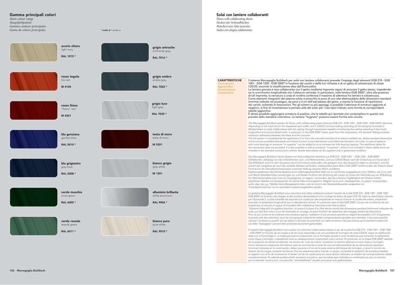
106 Marcegaglia Buildtech Marcegaglia Buildtech 107
* simile al * similar to
rosso tegola tile red
M 4104
avorio chiaro light ivory
RAL 1015 *
grigio ombra umbra grey
RAL 7022 *
grigio antracite anthracite grey
RAL 7016 *
verde reseda reseda green
RAL 6011 *
verde muschio moss green
RAL 6005 *
blu grigiastro grey blue
RAL 5008 *
blu genziana gentian blue
RAL 5010 *
rosso Siena “Siena” red
M 4301
grigio luce light grey
RAL 7035 *
testa di moro testa di moro
M 5301
bianco grigio grey white
M 1301
bianco puropure white
RAL 9010 *
alluminio brillantewhite aluminium
RAL 9006 *
Gamma principali coloriMain colour range Hauptfarbpalette Gamme couleurs principales Gama de colores principales
CARATTERISTICHECharacteristics EigenschaftenCaractéristiquesCaracterísticas
Il sistema Marcegaglia Buildtech per solai con lamiere collaboranti prevede l’impiego degli elementi EGB 210 - EGB 1001 - EGB 1200 - EGB 2000® in funzione dei carichi e delle luci richieste e di un getto di calcestruzzo di classe C20/25, secondo la classificazione data dall’Eurocodice.La lamiera grecata è resa collaborante con il getto mediante impronte capaci di ancorare il getto stesso, impedendo sia lo scorrimento longitudinale che il distacco verticale. In particolare, nella lamiera EGB 2000®, oltre alla presenza di tali impronte, la nervatura a coda di rondine conferisce il massimo di aderenza fra lamiera e calcestruzzo.Come elementi integrativi del sistema solaio è prescritta la posa di una rete elettrosaldata delle dimensioni standard (minime) indicate nel prosieguo, da porsi a 2 cm dall’estradosso del getto, e avente la funzione di ripartizione dei carichi, evitando le fessurazioni. Per gli schemi su più appoggi, è possibile l’adozione di armatura aggiunta al negativo, al fine di incrementare la portata utile dei solai: per i casi tipici indicati, sono fornite le corrispondenti tabelle aggiuntive. È altresì possibile aggiungere armatura al positivo, che le tabelle qui riportate non contemplano in quanto non prevista dallo standard costruttivo. Le lamiere “bugnate” possono essere fornite solo zincate.
The Marcegaglia Buildtech system for floors, with collaborating plates features EGB 210 - EGB 1001 - EGB 1200 - EGB 2000® elements, depending on the load and on the requested span width, and a C20/25 concrete casting according to the listing by Eurocode 2.Worked sheet is made collaborating with the casting through impressions capable of anchoring the casting impeding it from both longitudinal and vertical detachment. In particular, in the EGB 2000® sheet, apart from the impressions, the dovetail ribbing provides maximum adherence between the sheet and the concrete.The loft system is completed by the application 2 cm from the concrete extrados of an electro-welded net, whose standard dimensions (minimum) are provided afterwards and whose function is load distribution and inhibit the formation of cracks. In case of patterns with more bearings an armature “in negative” can be added so as to increase the lofts bearing capacity. The additional tables for the mentioned cases are provided. It is also possible to add an armature “in positive”, which is not included in these tables since not included in the standard construction scheme. Buckle steel plates can be supplied only in galvanized condition.
Das Marcegaglia Buildtech Decke-System mit Verbundblechen bestehet aus EGB 210 - EGB 1001 - EGB 1200 - EGB 2000® Stahlblechen, abhängig von den erforderlichen Last- und Weitenwerten, und aus C20/25 Beton nach der Einstufung von Eurocode 2. Das Riffelblech wird mit dem Gussstück durch Formräume verbunden, die geeignet sind, das Gussstück selbst zu verankern, und die sowohl den Längsfluss als auch das vertikale Ablösen verhindern. Insbesondere beim Blech EGB 2000® verleiht außer der Präsenz dieser Formräume die Schwalbenschwanzrippe maximale Haftung zwischen Blech und Beton.Ergänzungselement des Decke-Systems ist ein elektrogeschweißtes Netz mit im nachhinein angegebenen (min.) Maßen, das 2 cm weit vom Beton Gewölberücken anzubringen ist, und dessen Funktion die Verteilung der Lasten ist, sowie die Verhinderung von Rißbildung. Für Mehrstützenpläne kann man ein Zusatzgerüst‚ im negativ’ verwenden, das die nützliche Tragfähigkeit der Decken erhöht: spezifische Tabellen mit Zusatzwerten für solche Fälle sind eingeführt. Möglich ist es auch, Zusatzgerüste‚ im positiv’ einzuwenden, wofür aber die o.g. Tabellen keine Bezugswerte listen, weil es nicht in der Standard-Bauweise vorgesehen ist.Tränenbleche können nur im verzinktem zustand ausgeliefert werden.
Le système Marcegaglia Buildtech pour planchers avec tôles collaborant prévoit l’emploi de la tôle EGB 210 - EGB 1001 - EGB 1200 - EGB 2000® en fonction des charges et des lumières demandées et d’un coulage de béton de type C20/ 25, selon la classification donnée par l’Eurocode 2. La tôle travaillée est associée à la coulée par des empreintes en mesure d’ancrer la coulée elle-même, empêchant aussi bien le glissement longitudinal que le décollement vertical. En particulier dans la tôle EGB 2000®, en plus de la présence de ces empreintes, la nervure en queue d’hirondelle offre l’adhérence maximale entre tôle et béton. Eléments intégratifs du système plancher: on prescrit la pose d’un filet électro-soudé des dimensions standard (minimum) indiquées de suite, qui doit être mise à 2 cm de l’extrados du coulage, et ayant fonction de répartition des charges, évitant les fissurations. Pour ce qui concerne les schémas avec plusieurs appuis, l’adoption d’une armature ajoutée au négatif est possible, à fin d’augmenter la portée utile des planchers: pour les cas typiques indiqués les tables correspondantes ajoutées sont données. Il est aussi possible rajouter l’armature au positif, qui les tables ci-données ne prévoient car cette armature n’est pas prévue par le standard constructif. Les tôles “bossagées” peuvent être produites seulement galvanisées.
El sistema Marcegaglia Buildtech para suelos con planchas colaborantes prevee el uso de la plancha EGB 210 - EGB 1001 - EGB 1200 - EGB 2000® en función de los cargos y de las luces requeridas y de una cantidad de hormigón de clase C20/25, según la clasificación dada por el Eurocódigo 2. La chapa grecada es colaborante con el hormigón gracias a unas hendiduras que aumentan la adherencia entre chapa y hormigón, impediendo tanto su desplazamiento longitudinal como vertical. En particular, en la chapa EGB 2000® además de la presencia de dichas hendiduras, los nervios de “cola de milano” producen la máxima adherencia entre chapa y hormigón.Como elementos integrantes del sistema suelo se recomienda el pose de una red eléctrosoldada de las dimensiones estandars (mínimas) indicadas en la continuación, deben ponerse a 2 cm de la parte externa del bloque de hormigón, y tener la función de división de los cargos, evitando las fisuras. Para los esquemas sobre más de un apoyo, es posible la adopción de armadura añadidoal negativo con el fin de incrementar el sostén útil de los suelos para los casos típicos indicados, se añaden las correspondientes tablas complementarias. Es además posible añadir armadura al positivo, que las tablas aquí referidas no contemplan ya que no previstopor el estandar constructivo. Las planchas “almohadilladas” pueden proveerse solo galbanizadas.
Solai con lamiere collaborantiFloors with collaborating sheetsDecken mit VerbundblechenPlanchers avec tôles associées Suelos con chapas colaborantes
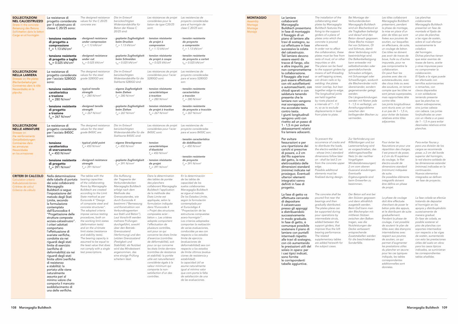
108 Marcegaglia Buildtech Marcegaglia Buildtech 109
SOLLECITAZIONI NEL CALCESTRUZZOStress in the concreteBelastung des BetonsSollicitation dans le bétonCarga en el hormigón
Le resistenze di progetto considerate per il calcestruzzo di classe C 20/25 sono:
- tensione resistente di progetto a compressione fcd= 1.13 kN/cm2
- tensione resistente di progetto a taglio tRd= 0.025 kN/cm2
The designed resistance values for the C 20/25 concrete are:
- designed resistance under compression fcd= 1.13 kN/cm2
- designed resistance under cut tRd= 0.025 kN/cm2
Die im Entwurf berücksichtigten Widerstandskräfte für Beton der Klasse C 20/25 sind:
- geplante Zugfestigkeit beim Drucken fcd= 1.13 kN/cm2
- geplante Zugfestigkeit beim Schneiden tRd= 0.025 kN/cm2
Les résistances de projet considérées pour le béton de type C20/25 sont:
- tension résistante de projet à compression fcd= 1.13 kN/cm2
- tension résistante de projet à coupe tRd= 0.025 kN/cm2
Las resistencias de proyecto consideradas para el hormigón de clase C 20/25 son:
- tensión resistente de proyecto a compresión fcd= 1.13 kN/cm2
- tensión resistente de proyecto a cortet tRd= 0.025 kN/cm2
SOLLECITAZIONI NELLA LAMIERAStresses on the platesBlechenbelastungenContraintes dans la tôleNecesidades en la plancha
Le resistenze di progetto considerate per l’acciaio S280GD sono:
- tensione resistente caratteristica a trazione fyp= 280 N/mm2
- tensione resistente di progetto a trazione fdp= 267 N/mm2
The designed resistance values for the steel grade S280GD are:
- typical tensile strength fyp= 280 N/mm2
- designed tensile strength fdp= 267 N/mm2
Die im Entwurf berücksichtigten Widerstandskräfte für die Stahlsorte S280GD sind:
- eigene Zugfestigkeit beim Ziehen fyp= 280 N/mm2
- geplante Zugfestigkeit beim Ziehen fdp= 267 N/mm2
Les résistances de projet considérées pour l’acier S280GD sont:
- tension résistante caractéristique à traction fyp= 280 N/mm2
- tension résistante de projet à traction fdp= 267 N/mm2
Las resistencias de proyecto consideradas para el acero S280GD son:
- tensión resistente característica a tracción fyp= 280 N/mm2
- tensión resistente de proyecto a tracción fdp= 267 N/mm2
SOLLECITAZIONI NELLE ARMATUREStresses on the reinforcementsGerüstbelastungenContraintes dans les armaturesNecesidades en los armazones
Le resistenze di progetto considerate per l’acciaio B450C sono:
- tensione caratteristica di snervamento fsk= 450 N/mm2
- tensione resistente di progetto fsd= 391 N/mm2
The designed resistance values for the steel grade B450C are:
- typical yield point fsk= 450 N/mm2
- designed resistance strength fsd= 391 N/mm2
Die im Entwurf berücksichtigten Widerstandskräfte für die Stahlsorte B450C sind:
- eigene Streckgrenze fsk= 450 N/mm2
- geplante Zugfestigkeit fsd= 391 N/mm2
Les résistances de projet considérées pour l’acier B450C sont:
- tension caractéristique d’élasticité fsk= 450 N/mm2
- tension résistante de projet fsd= 391 N/mm2
Las resistencias de proyecto consideradas para el acero B450C son:
- tensión característica de debilitación fsk= 450 N/mm2
- tensión resistente de proyecto fsd= 391 N/mm2
CRITERI DI CALCOLOCalculation criteriaKalkulationskriterienCritières de calculCriterios de cálculo
Nella determinazione delle tabelle di portata dei solai collaboranti Marcegaglia Buildtech si segue l’impostazione del metodo degli Stati Limite, secondo la formulazione contemplata dall’Eurocodice 4 “Progettazione delle strutture composte acciaio-calcestruzzo”. I criteri adottati comportano l’effettuazione di svariate verifiche, condotte sia nei riguardi degli stati limite di esercizio (verifiche di deformabilità) sia nei riguardi degli statilimite ultimi (verifiche di resistenza e stabilità): la portata utile viene naturalmente assunta pari al minimo valore che comporta il mancato soddisfacimento di una delle verifiche.
The tables with the bearing capacities of the collaborating floors by Marcegaglia Buildtech are created according to the Limit State method as per Eurocode 4 “Design of composite steel and concrete structures”. The adopted criteria impose various testing procedures, both on the working limit states (deformation tests) and on the ul-timate limit states (resistance and stability tests). The bearing capacity is assumed to be equal to the least value that does not comply with a single test prescriptions.
Die Auflistung der Tragwerte der Verbundendecken Marcegaglia Buildtech erfolgt nach dem Methode des Grenzzustandes, wie durch Eurocode 4 bestimmt (“Bemessung und Konstruktion von Verbundtragwerken aus Stahl und Beton”). Laut Vorschrift werden mehrere Prüfungen durchgeführt, sowohl über den Betrieb-Grenzzustand (Verformung) und den Letzten Grenzzustand (Festigkeit und Stabilität): als Nutzlast wird das Mindestwert angenommen, das eine einzige Prüfung scheitern lässt.
Dans la détermination des tables de portée des planchers collaborant Marcegaglia Buildtech l’application de la méthode des Etats Limite est appliquée, selon la formulation indiquée dans l’Eurocode 4 « Projet des structures composées acier - béton ». Les critères adoptés comportent l’effectuation de plusieurs contrôles, soit pour ce qui concerne les états limite d’exercice (contrôles de déformabilité), soit pour ce qui concerne les états limite derniers (contrôles de résistance et stabilité): la portée utile est naturellement considérée égale à la valeur minimum qui comporte la non- satisfaction d’un des contrôles.
En la determinación de las tablas de capacidad de los suelos colaborantes Marcegaglia Buildtech se sigue el métodoDe los Estados Límite, según la formulación contemplada por el Eurocódigo 4 “Proyectación de las estructuras compuestas acero-hormigón”. Los criterios adoptados comportan la realización de varias evaluaciones, conducidas ya sea con respecto a los estados límite de ejercicio (evaluaciones de deformabilidad) sea con respecto a los estados de límite últimos (evalua-ciones de resistencia y estabilidad): la capacidad útil seasume naturalmente igual al mínimo valor que com-porta la falta de satisfacción de una de las evaluaciones.
MONTAGGIOAssemblyMontageMontageMontaje
Le lamiere collaboranti Marcegaglia Buildtech presentano in fase di montaggio il fissaggio di un piano di lamiere alle travi di sostegno, su cui effettuare in fase successiva la colata del calcestruzzo. Tali lamiere devono essere esenti da tracce di fango, olio e altre impurità, per non comprometterne la collaborazione. Il fissaggio alle travi può essere effettuato con viti autofilettanti o automaschianti, con chiodi sparati o con saldature tenendo presente che le lamiere non vengono mai sovrapposte, ma accostate testa contro testa. I giunti longitudinali vengono uniti con rivetto ad un passo di 1 - 1,5 m per evitare abbassamenti relativi fra lamiere adiacenti.
Per evitare fessurazioni e per una ripartizione dei carichi si prescrive di posare, a 2 cm dal filo superiore del getto, la rete elettrosaldata delle dimensioni standard (minime) indicate nel prosieguo. Eventuali ulteriori elementi integrativi vanno definiti in fase di progetto.
La fase di getto va effettuata cercando di depositare il calcestruzzo presso gli appoggi e distribuendolo successivamente in modo graduale.In fase di getto, è comunque possibile sostenere il piano di lamiere con puntelli intermedi rispetto alle travi di sostegno, con ciò aumentando le prestazioni utili del solaio in opera: per i casi tipici indicati, sono fornite le corrispondenti tabelle aggiuntive.
The installation of the collaborating steel plates by Marcegaglia Buildtech features the fixing to the support girders of a plane of plates onto which the concrete is poured afterwards. In order not to affect the collaboration, these plates must be free from rests of mud, oil or other impurities or dirt. The plane can be fixed to the support girders by means of self-threading or self-tapping screws, con driven nails or by welding: the plates never overlap, but lean together edge-to-edge. The longitudinal joints are held together by rivets placed at a intervals of 1 - 1.5 m, so as to exclude displacements in level from plate to plate.
To prevent the occurrence of cracks and to distribute the loads, the electro-welded net - whose (min.) standard dimensions follow later on - shall be laid 2 cm from the concrete upper edge. Possible additional elements must be finalized during design.
The concrete shall be poured first near the bearings and then gradually distributed. The plates plane can be supported during pour operations by intermediate struts, added between the support girders, that improve thus the loft bearing performance. The related supplementary tables are added herewith for the subject cases.
Bei Montage der Verbundendecken Marcegaglia Buildtech wird ein Blechenbord an die Tragbalken befestigt und darauf wird den Beton danach gegossen. Diese Bleche müssen frei von Schlamm, Öl und Schmutz, damit derer Verbindung nicht beeinträchtigt wird.Die Balkenbefestigung kann entweder mit selbstbohrenden oder gewindefurchende Schrauben erfolgen, mit Schussnagel oder Schweißungen, wodurch die Blechenränder nicht übereinander, sondern gegeneinander gelegt werden.Die Längsverbindungen werden mit Nieten jede 1 - 1,5 m verfestigt, um Anreihungsprobleme zwischen den beiliegenden Blechen zu vermeiden.
Zur Verhinderung von Rißbildungen und zur Lastenverteilung wird es vorgeschrieben, das elektrogeschweißte Netz (in der nachher hingefügten Mindestabmessungen) 2 cm vom oberen Gussrand anzubringen. Eventuelle Ergänzungsteile sind beim Entwerfen zu bestimmen.
Der Beton soll erst bei den Stützen gegossen und dann allmählich ausgeteilt werden. Beim Guß kann man den Blechenplan mit mittleren Stützen zwischen den Balken tragen, was die Nutzleistungen der Decke verbessert: entsprechende Zusatztabellen werden für die beschriebenen Sonderfälle.
Les tôles collaborant Marcegaglia Buildtech présentent, pendant la phase de montage, la mise en place d’un plan de tôles qui sont fixées aux poutres de soutien, sur lesquelles on effectuera, de suite, un coulage de béton. Ces tôles ne doivent pas avoir de traces de boue, huile ou d’autres impuretés, pour ne pas compromettre la collaboration.On peut fixer les poutres avec des vis autotaraudeures, avec des clous tirés ou avec des soudures, en tenant compte que les tôles ne sont jamais superposées, mais rapprochées tête contre tête. Les joints longitudinaux sont réunis avec un rivet à un pas de 1 - 1,5 m, pour éviter de baisses relatives entre tôles adjacentes.
Pour éviter les fissurations et pour une répartition des charges, il est prescrit de poser, à 2 cm du fil supérieur du coulage, le filet électro-soudé de dimensions standard (minimum) indiquées de suite. De possibles éléments intégratifs doivent être définis en phase de projet.
La phase de coulage doit être effectuée cherchant de poser le béton près des appuis, et le distribuant de suite graduellement. Pendant la phase de coulage, il est possible de soutenir le plan de tôles avec des étançons intermédiaires avec respect aux poutres de soutien, ce qui permet d’augmenter les prestations utiles du plancher en œuvre: pour les cas typiques indiqués, les tables correspondantes additionnelles sont données.
Las planchas colaborantes Marcegaglia Buildtech presentan en fase de montado el fijado de un piso de planchas a las vigas de sostén, sobre el cual efectuar sucesivamente la coladura del hormigón. Dichas planchas tienen que estar exentas de trazas de barro, aceite y otras impurezas para no comprometer la colaboración.El fijado a la vigas puede ser efectuado con tornillos autorroscantes o remaches, con clavos disparados o con soldaduras teniendo presente que las planchas no deben sobreponerse, sino juntas cabeza con cabeza. Las juntas lonjitudinales se unen con un ribete a un paso de 1 - 1,5 m para evitar desniveles relativos entre planchas.
Para evitar fisuras y para una división de los cargos se recomienda posar, a 2 cm del borde superior del hormigón, la red electro-soldada de las dimensiones estandar (mínimas) indicadas en la continuación. Nuevos elementos integrados se definen en fase de proyecto.
La fase colada se efectúa tratando de depositar el hormigón en los apoyos y distribuyéndolo sucesivamente de manera gradual.En fase de colada, es posible sostener el piso de planchas con soportes intermedios con respecto a las vigas de sostén, aumentando con esto las prestaciones útiles del suelo en obra: para los casos típicos indicados, se suministran las correspondientes tablas añadidas.

110 Marcegaglia Buildtech Marcegaglia Buildtech 111
Trave composta acciaio calcestruzzoBeam composed of steel-reinforced concreteAus Stahlbeton bestehender Träger Poutre mélangée acier-bétonViga de acero-hormigón
Fissaggio come solaio tradizionaleFixing like a traditional floor slabBefestigung wie bei herkömmlicher DeckeFixation comme plancher traditionnelFijación como suelo tradicional
Chiodo sparato o vite autofilettante o vite automaschianteShot nail or self-threading screwor self-tapping screw
VERIFICHE IN FASE DI GETTOTests during pouringPrüfungen während GiessenContrôles en phase de coulageEvaluaciones en fase de colada
RESISTENZA Si considerano i valori del momento resistente di progetto della lamiera, per i due casi di fibre tese inferiori o superiori, e si confrontano con i corrispondenti valori del momento sollecitante.Le caratteristiche resistenti vengono calcolate secondo EC3 - parte 1.3 e dipendono, fra l’altro, da spessore e resistenza del materiale; le caratteristiche sollecitanti sono calcolate sulla scorta degli schemi statici (1, 2 o N campate) in fase di getto, sia per il caso - standard - senza puntellazione che per l’alternativa con puntellazione intermedia fra gli appoggi in esercizio.
DEFORMABILITÀ Viene assunta una freccia massima pari a L/250 (L: interasse, costante, fra gli appoggi o i puntelli), e comunque non superiore a 2 cm: ciò al fine di confermare l’assunzione di carico uniformemente distribuito, potendosi ignorare l’effetto di accumulo del calcestruzzo fresco in campata.
Il valore del momento d’inerzia J, per la sezione di lamiera, è calcolato in funzione del livello tensionale raggiunto in corrispondenza del carico dovuto alla combinazione per stati limite di esercizio.
RESISTANCE For the two cases of tensioned fibers, upper and lower, the design values of the plate’s resistant moment are compared with the corresponding values of the stress moment. The resistant properties are figured out according to Eurocode 3 - Part 1-3 and depend also on the material thickness and resistance. The stress properties are figured out on the basis of the static patterns (1, 2 or N bays) while pouring - either for the ordinary case without struts, or for the alternative one with intermediate struts among the bearings.
DEFORMABILITY The max. assumed deviation amounts to L/250 (L: inter-axis, constant, between bearings or struts), and in any case cannot exceed 2 cm: this to confirm the assumption of an uniformly distributed load, being the accumulation effect of fresh concrete along the bay not significant.
The moment of inertia J is calculated, for the plate’s section, upon the tensioning level achieved by the load due to the limit states combination.
FESTIGKEIT Für die zwei Fälle gespannter Fiber, oberer und unterer, werden die Planungswerte des Widerstandsmoment der Bleche mit den entsprechenden Werten des Antriebsmoments verglichen.Die mechanischen Eigenschaften werden nach Eurocode 3 - Teil 1-3 berechnet und hängen unter anderem von Dicke und Festigkeit des Vormaterials. Die Antriebeigenschaften werden auf der Basis der statischen Pläne beim Giessen berechnet (1, 2 oder N Spannweiten) - für die beiden Fälle, mit und ohne den mittleren Hilfsstützen.
VERFORMBARKEIT Eine max. Abweichung von L/250 (L = regelmäßiger Achsenabstand zwischen Stützen) ist zugelassen, die 2 cm auf jeden Fall nicht überschreiten darf. Damit wird den Last gleichmäßig verteilt, und die Wirkung der frischen Betonanhäufung der Spannweite entlang nicht in Betracht genommen.
Das Wert des Trägheitsmoments auf den Blechenschnitt wird in Zusammenhang mit dem Spannungswert berechnet, das mit der Belastung erreicht wird, die zur Kombinierung bei den Grenzzuständen zurückzuführen ist.
RESISTANCE Il faut considérer les valeurs du moment résistants de projet de la tôle pour les deux cas de fibres tendues inférieures ou supérieures, et on compare les valeurs correspondantes pendant le moment sollicitant.Les caractéristiques résistantes sont calculées selon EC3 - partie 1.3 et dépendent, entre outre, de l’épaisseur et de la résistance du matériel; les caractéristiques d’élasticité sont calculées sur la base des schémas statiques (1, 2 ou N portées) en phase de coulage, soit pour le cas - standard - sans étançonnement, soit pour l’alternative avec étançonnement intermédiaire entre les appuis en exercice.
DÉFORMABILITÉ On considère une flèche maximum égale à L/250 (L: entraxe, constant, entre les appuis ou les étançons), et en tout cas, pas supérieur à 2 cm: ça sert pour confirmer la thèse de charge uniformément distribué, du moment qu’on peut ignorer l’effet d’accumulation du béton frais sur la portée.
Le valeur du moment d’inertie J, pour la section de tôle, est calculée en fonction du niveau de tension rejoint en correspon-dance du charge, du à la combinaison pour états limite d’exercice.
RESISTÉNCIA Se consideran los valores del momento resistente de proyecto de la plancha, para los dos casos de fibras tensas inferiores o superiores, y se comparan con los correspondientes valores del momento requerido. Las características resistentes se calculan según EC3 - parte 1.3 y dependen, entre otras cosas, del espesor y resisténcia del material, las características requeridas se calculan sobre la reserva de los esquemas estaticos (1, 2 o N travesaños) en fase de colada, sea para el caso - estandar - sin apuntelar que para la alternativa con apuntelación intermedia entre los apoyos en ejercicio.
DEFORMABILIDAD Se asume con una flecha máxima igual a L/250 (eje intermedio, constante, entre los apoyos o los puntales), y de cualquier modo no superior a 2 cm: esto con el fin de confirmar el cargo uniformemente distribuido, pudiéndose ignorar el efecto de acu-mulación del hormigón fresco en travesaños.
El valor del momento de inercia J, para la sección de plancha, está calculado en función del nivel de tensión conseguido en correspondencia del cargo debido a la combinación por estados límite de ejercicio.
VERIFICHE IN FASE DI ESERCIZIOTests during workPrüfungen während AntriebContrôles en phase d’exerciceEvaluaciones en fase de ejercicio
Ad avvenuta maturazione del getto, si considera una sezione in c.a. in cui lamiera e rete elettrosaldata svolgono le funzioni di armatura longitudinale e staffe.
RESISTENZAPer la sezione di soletta si considerano le verifiche a flessione, taglio e scorrimento previste da EC4; tali verifiche, corrispondenti a stati limite ultimi, sono condotte sulla scorta delle sollecitazioni di progetto (momenti flettenti e tagli) per il caso di carico utile uniformemente distribuito su tutte le campate (1, 2 o N) previste dagli schemi tabellati.Parallelamente, si considerano i pertinenti parametri resistenti di progetto, valutati secondo quanto schematicamente indicato al seguito.
Momento resistente positivo di progetto (M+
Rd)Per il valore di questo parametro, occorre preventivamente calcolare la posizione dell’asse neutro plastico della sezione, distinguendo i casi di asse neutro “in soletta” o “in lamiera”; il contributo resistente offerto dalla lamiera come armatura al positivo, poi, dipende direttamente dalla quota tensionale precedentemente impiegata in fase di getto.
Momento resistente negativo di progetto (M-
Rd)Il valore di questo parametro è calcolato trascurando completamente i contributi della lamiera grecata e del calcestruzzo teso: le risorse resistenti fanno capo al calcestruzzo compresso e all’armatura al negativo, che nel caso standard è costituita dalla prescritta rete elettrosaldata.
Once the concrete has compacted, a section of rein-forced concrete is taken in consideration, where electro-welded net and plate function as longitudinal mat and bracket.
RESISTANCEThe slab section is interested by bending, cutting and slipping tests as prescribed by the Eurocode 4. The tests, corresponding to ultimate limit states, are carried out on the basis of the design stresses (bending moments and cuts), concerning the case of live load uniformly distributed over all the bays (1, 2 or N) listed by the tables.At the same time, the evaluation of the pertaining resistant parameters according to the design proceeds as per the criteria hereafter described.
Positive, design resistant moment (M+
Rd)The calculation of the position of the neutral, plastic axis of the sectionis the prerequisite to figure this parameter’s value; a distinction must be made between neutral axes “in the slab” or “in the plate”; the plate resistance contribution as positive reinforcement depends then on the tension level previously generated in the pouring stage.
Negative, design resistant moment (M-
Rd)The contributions of corrugated plate and compacted concrete are ignored in the calculation of this parameter’s value: the resistant forces go back to the compressed concrete and to the negative reinforcement, which in the ordinary case consists of the prescribed, electro-welded net.
Nachdem der Beton fertig ist, man nimmt einen Schnitt von Eisenbeton an, wo Bleche und elektrogeschweißtes Netz die Funktionen von Längsgerüst und Behälter aufnehmen.
FESTIGKEITDie Sohle bzw. ihr Schnitt wird laut Eurocode 4 geprüft; es werden Biege-, Schneide- und Gleitungsprüfungen bei Grenzzuständen durchgeführt, auf der Basis der geplanten Beanspruchungen (Biegemomente und Schnitt). Dies im Falle eines Nutzlastes, das gleichmäßig über allen in der Tabelle aufgestellten Spannweiten (1, 2 o N) verteilt ist.Parallel werden die nach Entwurf dazukommenden Widerstandsparameter berücksichtigt und wie folgt bewertet.
Positiver Widerstandsmoment nach Entwurf (M+
Rd)Um das Wert dieses Parameters zu berechnen, muss man im voraus die Position der plastischen Schnittachse kennen und darauf beachten, die neutralen Achsen “in der Sohle” von denen “in der Bleche” zu unterscheiden. Der von der Bleche geleistete Widerstand als positives Gerüst hängt direkt von der Spannungsquote, die beim Giessen berücksichtigt wurde.
Negativer Widerstandsmoment nach Entwurf (M-
Rd)Für die Berechnung dieses Parameters werden die Beiträge von Wellblech und gespanntem Beton unterlassen. Die Widerstandsquellen sind der gedruckte Beton und das negative Gerüst, das normalerweise aus dem elektrogeschweißtem Netz besteht.
Quand le coulage a été effectué, il faut considérer une section en c.a. ou la tôle et le filet électro-soudé ont une fonction d’armature longitudinale et étriers.
RESISTANCEPour la fonction de semelle, il faut considérer les contrôles à flexion, coupe et écoulement prévues par EC4; ces contrôles, qui correspondent aux états de limite derniers, son conduits sur la base des contraintes de projet (moments fléchissant et coupes) dans le cas de charge utile uniformément distribué sur toutes les portées (1, 2, ou N) prévues par les schémas dans les tables. Parallèlement, il faut considérer les pertinents paramètres résistant de projet, évalués selon ce qui vient indiqué schématiquement ci-dessous.
Moment de résistance positive de projet (M+
Rd)Pour la valeur de ce paramètre il faut calculer d’avance la position de l’axe neutre plastique de la section, distinguant les cas d’axe neutre «en semelle» ou «en tôle d’acier»; la contribution résistante offerte par la tôle comme armature au positif, ensuite, dépend directement de la partie en tension utilisée précédemment en phase de coulage.
Moment de résistance négative de projet (M-
Rd)La valeur de ce paramètre est calculée ignorant complètement les contributions de la tôle travaillée et du béton tendu: les ressources résistantes s’appuient au béton comprimé et à l’armature au négatif, qui, dans le cas standard, est constituée par la partie électro-soudée prescrite.
Una vez realizada la maduración de la colada, se considera una sección en c.a en cuya plancha y red electrosoldada se desarrollan las funciones de armadura longitudinal y estribos.
RESISTÉNCIAPara la sección de losa se consideran las evaluaciones a flexión, corte y deslizamiento previstas por EC4, tales evaluaciones, correspondientes a estados límite últimos, se conducen sobre las reservas de las solicitaciones de proyecto (momentos plegados y cortes) para el caso de cargo útil uniformemente distribuido sobre todos los travesaños (1,2 o N) previstas por los esquemas de las tablas. Paralelamente se consideran los pertinentes parámetros resistentes de proyecto, valorados según cuanto indicado esquemáticamente a continuación.
Momento resistente positivo de proyecto (M+
Rd)Para el valor de este parámetro, es necesario calcular preventivamente la posición del eje neutro plástico de la sección, distinguiendo los casos de eje neutro “en losa” o “en plancha”, la contribución resistente ofrecida por la plancha como armazón al positivo, después, depende directamente de la cuota de tensión empleada precedentemente en fase de colada.
Momento resistente negativo de proyecto (M-
Rd)El valor de este parámetro está calculado olvidando completamente las contribuciones de la plancha grecada y del hormigón tenso: los recursos resistentes superan al hormigón comprendido y al armazón al negativo, que en el caso estandar está formada por la red electrosoldada recomendada.
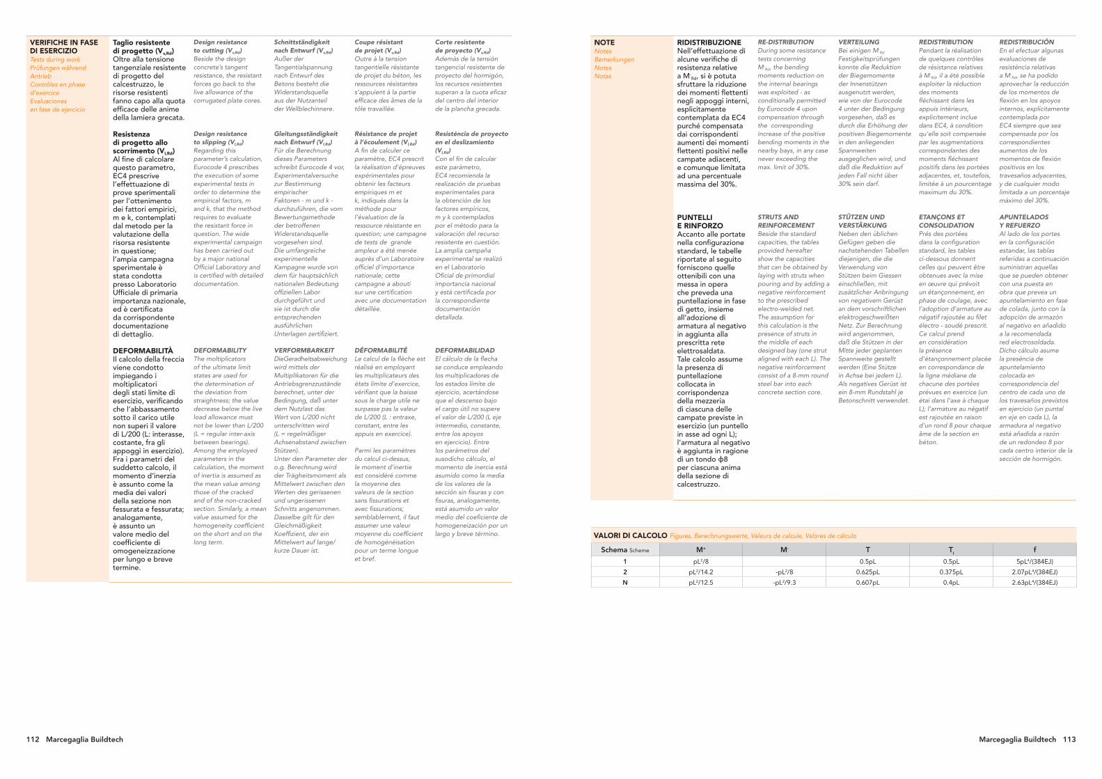
112 Marcegaglia Buildtech Marcegaglia Buildtech 113
VERIFICHE IN FASE DI ESERCIZIOTests during workPrüfungen während AntriebContrôles en phase d’exerciceEvaluaciones en fase de ejercicio
Taglio resistente di progetto (Vv,Rd)Oltre alla tensione tangenziale resistente di progetto del calcestruzzo, le risorse resistenti fanno capo alla quota efficace delle anime della lamiera grecata.
Resistenza di progetto allo scorrimento (Vl,Rd)Al fine di calcolare questo parametro, EC4 prescrive l’effettuazione di prove sperimentali per l’ottenimento dei fattori empirici, m e k, contemplati dal metodo per la valutazione della risorsa resistente in questione; l’ampia campagna sperimentale è stata condotta presso Laboratorio Ufficiale di primaria importanza nazionale, ed è certificata da corrispondente documentazione di dettaglio.
DEFORMABILITÀ Il calcolo della freccia viene condotto impiegando i moltiplicatori degli stati limite di esercizio, verificando che l’abbassamento sotto il carico utile non superi il valore di L/200 (L: interasse, costante, fra gli appoggi in esercizio).Fra i parametri del suddetto calcolo, il momento d’inerzia è assunto come la media dei valori della sezione non fessurata e fessurata; analogamente, è assunto un valore medio del coefficiente di omogeneizzazione per lungo e breve termine.
Design resistance to cutting (Vv,Rd)Beside the design concrete’s tangent resistance, the resistant forces go back to the live allowance of the corrugated plate cores.
Design resistance to slipping (Vl,Rd)Regarding this parameter’s calculation, Eurocode 4 prescribes the execution of some experimental tests in order to determine the empirical factors, m and k, that the method requires to evaluate the resistant force in question. The wide experimental campaign has been carried out by a major national Official Laboratory and is certified with detailed documentation.
DEFORMABILITY The moltiplicators of the ultimate limit states are used for the determination of the deviation from straightness; the value decrease below the live load allowance must not be lower than L/200 (L = regular inter-axis between bearings).Among the employed parameters in the calculation, the moment of inertia is assumed as the mean value among those of the cracked and of the non-cracked section. Similarly, a mean value assumed for the homogeneity coefficient on the short and on the long term.
Schnittständigkeit nach Entwurf (Vv,Rd)Außer der Tangentialspannung nach Entwurf des Betons besteht die Widerstandsquelle aus der Nutzanteil der Wellblechinnere.
Gleitungsständigkeit nach Entwurf (Vl,Rd)Für die Berechnung dieses Parameters schreibt Eurocode 4 vor, Experimentalversuche zur Bestimmung empirischer Faktoren - m und k - durchzuführen, die vom Bewertungsmethode der betroffenen Widerstandsquelle vorgesehen sind. Die umfangreiche experimentelle Kampagne wurde von dem für hauptsächlich nationalen Bedeutung offiziellen Labor durchgeführt und sie ist durch die entsprechenden ausführlichen Unterlagen zertifiziert.
VERFORMBARKEIT Die Geradheitsabweichung wird mittels der Multiplikatoren für die Antriebsgrenzzustände berechnet, unter der Bedingung, daß unter dem Nutzlast das Wert von L/200 nicht unterschritten wird (L = regelmäßiger Achsenabstand zwischen Stützen).Unter den Parameter der o.g. Berechnung wird der Trägheitsmoment als Mittelwert zwischen den Werten des gerissenen und ungerissenen Schnitts angenommen. Dasselbe gilt für den Gleichmäßigkeit Koeffizient, der ein Mittelwert auf lange/kurze Dauer ist.
Coupe résistant de projet (Vv,Rd)Outre à la tension tangentielle résistante de projet du béton, les ressources résistantes s’appuient à la partie efficace des âmes de la tôle travaillée.
Résistance de projet à l’écoulement (Vl,Rd)A fin de calculer ce paramètre, EC4 prescrit la réalisation d’épreuves expérimentales pour obtenir les facteurs empiriques m et k, indiqués dans la méthode pour l’évaluation de la ressource résistante en question; une campagne de tests de grande ampleur a été menée auprès d’un Laboratoire officiel d’importance nationale; cette campagne a abouti sur une certification avec une documentation détaillée.
DÉFORMABILITÉ Le calcul de la flèche est réalisé en employant les multiplicateurs des états limite d’exercice, vérifiant que la baisse sous le charge utile ne surpasse pas la valeur de L/200 (L : entraxe, constant, entre les appuis en exercice).
Parmi les paramètres du calcul ci-dessus, le moment d’inertie est considéré comme la moyenne des valeurs de la section sans fissurations et avec fissurations; semblablement, il faut assumer une valeur moyenne du coefficient de homogénéisation pour un terme longue et bref.
Corte resistente de proyecto (Vv,Rd)Además de la tensión tangencial resistente de proyecto del hormigón, los recursos resistentes superan a la cuota eficaz del centro del interior de la plancha grecada.
Resisténcia de proyecto en el deslizamiento (Vl,Rd)Con el fin de calcular este parámetro, EC4 recomienda la realización de pruebas experimentales para la obtención de los factores empíricos, m y k contemplados por el método para la valoración del recurso resistente en cuestión.La amplia campaña experimental se realizó en el Laboratorio Oficial de primordial importancia nacional y está certificada por la correspondiente documentación detallada.
DEFORMABILIDAD El cálculo de la flecha se conduce empleando los multiplicadores de los estados límite de ejercicio, acertándose que el descenso bajo el cargo útil no supere el valor de L/200 (L eje intermedio, constante, entre los apoyos en ejercicio). Entre los parámetros del susodicho cálculo, el momento de inercia está asumido como la media de los valores de la sección sin fisuras y con fisuras, analogamente, está asumido un valor medio del coeficiente de homogeneización por un largo y breve término. VALORI DI CALCOLO Figures, Berechnungswerte, Valeurs de calcule, Valores de cálculo
Schema Scheme M+ M- T TI f
1 pL2/8 0.5pL 0.5pL 5pL4/(384EJ)
2 pL2/14.2 -pL2/8 0.625pL 0.375pL 2.07pL4/(384EJ)
N pL2/12.5 -pL2/9.3 0.607pL 0.4pL 2.63pL4/(384EJ)
NOTENotesBemerkungenNotesNotas
RIDISTRIBUZIONE Nell’effettuazione di alcune verifiche di resistenza relative a M-
Rd, si è potuta sfruttare la riduzione dei momenti flettenti negli appoggi interni, esplicitamente contemplata da EC4 purché compensata dai corrispondenti aumenti dei momenti flettenti positivi nelle campate adiacenti, e comunque limitata ad una percentuale massima del 30%.
PUNTELLI E RINFORZO Accanto alle portate nella configurazione standard, le tabelle riportate al seguito forniscono quelle ottenibili con una messa in opera che preveda una puntellazione in fase di getto, insieme all’adozione di armatura al negativo in aggiunta alla prescritta rete elettrosaldata.Tale calcolo assume la presenza di puntellazione collocata in corrispondenza della mezzeria di ciascuna delle campate previste in esercizio (un puntello in asse ad ogni L); l’armatura al negativo è aggiunta in ragione di un tondo ϕ8 per ciascuna anima della sezione di calcestruzzo.
RE-DISTRIBUTION During some resistance tests concerning M-
Rd, the bending moments reduction on the internal bearings was exploited - as conditionally permitted by Eurocode 4 upon compensation through the corresponding increase of the positive bending moments in the nearby bays, in any case never exceeding the max. limit of 30%.
STRUTS AND REINFORCEMENT Beside the standard capacities, the tables provided hereafter show the capacities that can be obtained by laying with struts when pouring and by adding a negative reinforcement to the prescribed electro-welded net.The assumption for this calculation is the presence of struts in the middle of each designed bay (one strut aligned with each L). The negative reinforcement consist of a 8-mm round steel bar into each concrete section core.
VERTEILUNG Bei einigen M-
Rd Festigkeitsprüfungen konnte die Reduktion der Biegemomente der Innenstützen ausgenutzt werden, wie von der Eurocode 4 unter der Bedingung vorgesehen, daß es durch die Erhöhung der positiven Biegemomente in den anliegenden Spannweiten ausgeglichen wird, und daß die Reduktion auf jeden Fall nicht über 30% sein darf.
STÜTZEN UND VERSTÄRKUNG Neben den üblichen Gefügen geben die nachstehenden Tabellen diejenigen, die die Verwendung von Stützen beim Giessen einschließen, mit zusätzlicher Anbringung von negativem Gerüst an dem vorschriftlichen elektrogeschweißten Netz. Zur Berechnung wird angenommen, daß die Stützen in der Mitte jeder geplanten Spannweite gestellt werden (Eine Stütze in Achse bei jedem L). Als negatives Gerüst ist ein 8-mm Rundstahl je Betonschnitt verwendet.
REDISTRIBUTION Pendant la réalisation de quelques contrôles de résistance relatives à M-
Rd, il a été possible exploiter la réduction des moments fléchissant dans les appuis intérieurs, explicitement inclue dans EC4, à condition qu’elle soit compensée par les augmentations correspondantes des moments fléchissant positifs dans les portées adjacentes, et, toutefois, limitée à un pourcentage maximum du 30%.
ETANÇONS ET CONSOLIDATION Prés des portées dans la configuration standard, les tables ci-dessous donnent celles qui peuvent être obtenues avec la mise en œuvre qui prévoit un étançonnement, en phase de coulage, avec l’adoption d’armature au négatif rajoutée au filet électro - soudé prescrit.Ce calcul prend en considération la présence d’étançonnement placée en correspondance de la ligne médiane de chacune des portées prévues en exercice (un étai dans l’axe à chaque L); l’armature au négatif est rajoutée en raison d’un rond 8 pour chaque âme de la section en béton.
REDISTRIBUCIÓN En el efectuar algunas evaluaciones de resisténcia relativas a M-
Rd, se ha podido aprovechar la reducción de los momentos de flexión en los apoyos internos, explícitamente contemplada por EC4 siempre que sea compensada por los correspondientes aumentos de los momentos de flexión positivos en los travesaños adyacentes, y de cualquier modo limitada a un porcentaje máximo del 30%.
APUNTELADOS Y REFUERZO Al lado de los portes en la configuración estandar, las tablas referidas a continuación suministran aquellas que se pueden obtener con una puesta en obra que prevea un apuntelamiento en fase de colada, junto con la adopción de armazón al negativo en añadido a la recomendada red electrosoldada. Dicho cálculo asume la preséncia de apuntelamiento colocada en correspondencia del centro de cada uno de los travesaños previstos en ejercicio (un puntal en eje en cada L), la armadura al negativo está añadida a razón de un redondeo 8 por cada centro interior de la sección de hormigón.

A
B
114 Marcegaglia Buildtech Marcegaglia Buildtech 115
Solai con lamiere collaborantiFloors with collaborating sheetsDecken mit VerbundblechenPlanchers avec tôles associées Suelos con chapas colaborantes
EGB 210 H=10 cm
EGB 210 H=10 cm 1 campata 1 span
Spessore Thickness Sovraccarico di esercizio utile uniformemente distribuito kN/m2 - Useful working overload, uniformly distributed (kN/m2)
mm 1,50 2,00 2,50 3,00 3,50 4,00 4,50 5,00 5,50 6,00 7,00 8,00 10,00 12,00 15,00 20,00
Luce massima in m per solai - Maximum span in m for floors
0,7 2.45 2.45 2.45 2.45 2.45 2.45 2.45 2.37 2.22 2.09 1.89 1.73 1.50 1.34 1.17 0.98
0,8 2.55 2.55 2.55 2.55 2.55 2.55 2.55 2.52 2.36 2.23 2.02 1.86 1.61 1.44 1.26 1.06
1,0 2.75 2.75 2.75 2.75 2.75 2.75 2.75 2.75 2.63 2.49 2.26 2.09 1.82 1.64 1.44 1.22
1,2 2.90 2.90 2.90 2.90 2.90 2.90 2.90 2.90 2.82 2.67 2.43 2.24 1.97 1.77 1.55 1.32
EGB 210 H=10 cm 2 campate 2 spans
Spessore Thickness Sovraccarico di esercizio utile uniformemente distribuito kN/m2 - Useful working overload, uniformly distributed (kN/m2)
mm 1,50 2,00 2,50 3,00 3,50 4,00 4,50 5,00 5,50 6,00 7,00 8,00 10,00 12,00 15,00 20,00
Luce massima in m per solai - Maximum span in m for floors
0,7 2.75 2.75 2.75 2.75 2.75 2.61 2.46 2.34 2.23 2.13 1.97 1.85 1.65 1.51 1.33 1.00
0,8 3.05 3.05 3.05 3.01 2.79 2.61 2.46 2.34 2.23 2.13 1.97 1.85 1.65 1.51 1.35 1.10
1,0 3.40 3.40 3.30 3.01 2.79 2.61 2.46 2.34 2.23 2.13 1.97 1.85 1.65 1.51 1.35 1.17
1,2 3.60 3.60 3.30 3.02 2.79 2.61 2.46 2.34 2.23 2.13 1.97 1.85 1.65 1.51 1.35 1.17
EGB 210 H=10 cm N campate N spans
Spessore Thickness Sovraccarico di esercizio utile uniformemente distribuito kN/m2 - Useful working overload, uniformly distributed (kN/m2)
mm 1,50 2,00 2,50 3,00 3,50 4,00 4,50 5,00 5,50 6,00 7,00 8,00 10,00 12,00 15,00 20,00
Luce massima in m per solai - Maximum span in m for floors
0,7 2.85 2.85 2.85 2.85 2.85 2.82 2.65 2.52 2.40 2.30 2.13 1.99 1.73 1.54 1.34 1.02
0,8 3.00 3.00 3.00 3.00 3.00 2.82 2.65 2.52 2.40 2.30 2.13 1.99 1.78 1.63 1.44 1.14
1,0 3.20 3.20 3.20 3.20 3.01 2.82 2.65 2.52 2.40 2.30 2.13 1.99 1.78 1.63 1.45 1.24
1,2 3.40 3.40 3.40 3.25 3.01 2.82 2.65 2.52 2.40 2.30 2.13 1.99 1.78 1.63 1.45 1.26
L’approccio generale del calcolo è quello dell’Eurocodice 4 “Progettazione delle strutture acciaio-calcestruzzo”, Parte 1-1 “Regole generali e regole per gli edifici”.The calculation approach is provided by the Eurocode 4 “Design of composite steel and concrete structures”, Part 1-1 “General rules and rules for building”.
EGB 210 H=10 cm
Caratteristiche del profilo Section properties
Spessore Thickness Peso Weight
Peso Weight
1000 1250
mm kg/m2 kg/m
0,7 9,16 5,50 6,87
0,8 10,47 6,28 7,85
1,0 13,08 7,85 9,81
1,2 15,70 9,42 11,78
1000 mm1250 mm
600 mm750 mm
sviluppo nastrostrip width
rete elettrosaldataelectrically-welded wire mesh
larghezza utilecoverage{ {
H
600 mm
55 mm
CARATTERISTICHECharacteristicsEigenschaftenCaractéristiquesCaracterísticas
Rete ø 6 mma maglia saldata da 150x150 mm
Grid ø 6 mm welded mesh 150x150 mm
Nutzung und Anwendung Geflecht ø 6 mm mit geschweißten Maschen zu 150x150 mm
Grille ø 6 mm à maille soudée de 150x150 mm
Malla electrosoldada 150x150 mm (Ø 6 mm)

116 Marcegaglia Buildtech Marcegaglia Buildtech 117
Solai con lamiere collaborantiFloors with collaborating sheetsDecken mit VerbundblechenPlanchers avec tôles associées Suelos con chapas colaborantes
EGB 210 H=11 cm
EGB 210 H=11 cm 1 campata 1 span
Spessore Thickness Sovraccarico di esercizio utile uniformemente distribuito kN/m2 - Useful working overload, uniformly distributed (kN/m2)
mm 1,50 2,00 2,50 3,00 3,50 4,00 4,50 5,00 5,50 6,00 7,00 8,00 10,00 12,00 15,00 20,00
Luce massima in m per solai - Maximum span in m for floors
0,7 2.35 2.35 2.35 2.35 2.35 2.35 2.35 2.35 2.35 2.28 2.06 1.88 1.63 1.45 1.26 1.06
0,8 2.50 2.50 2.50 2.50 2.50 2.50 2.50 2.50 2.50 2.43 2.19 2.01 1.75 1.56 1.36 1.15
1,0 2.75 2.75 2.75 2.75 2.75 2.75 2.75 2.75 2.75 2.71 2.47 2.27 1.98 1.78 1.56 1.32
1,2 2.90 2.90 2.90 2.90 2.90 2.90 2.90 2.90 2.90 2.90 2.64 2.44 2.13 1.92 1.68 1.43
EGB 210 H=11 cm 2 campate 2 spans
Spessore Thickness Sovraccarico di esercizio utile uniformemente distribuito kN/m2 - Useful working overload, uniformly distributed (kN/m2)
mm 1,50 2,00 2,50 3,00 3,50 4,00 4,50 5,00 5,50 6,00 7,00 8,00 10,00 12,00 15,00 20,00
Luce massima in m per solai - Maximum span in m for floors
0,7 2.60 2.60 2.60 2.60 2.60 2.60 2.60 2.50 2.38 2.28 2.11 1.97 1.77 1.61 1.44 1.08
0,8 2.90 2.90 2.90 2.90 2.90 2.79 2.63 2.50 2.38 2.28 2.11 1.97 1.77 1.61 1.44 1.20
1,0 3.35 3.35 3.35 3.23 2.99 2.79 2.63 2.50 2.38 2.28 2.11 1.97 1.77 1.61 1.44 1.25
1,2 3.55 3.55 3.53 3.23 2.99 2.79 2.63 2.50 2.38 2.28 2.11 1.97 1.77 1.61 1.44 1.25
EGB 210 H=11 cm N campate N spans
Spessore Thickness Sovraccarico di esercizio utile uniformemente distribuito kN/m2 - Useful working overload, uniformly distributed (kN/m2)
mm 1,50 2,00 2,50 3,00 3,50 4,00 4,50 5,00 5,50 6,00 7,00 8,00 10,00 12,00 15,00 20,00
Luce massima in m per solai - Maximum span in m for floors
0,7 2.70 2.70 2.70 2.70 2.70 2.70 2.70 2.69 2.57 2.46 2.28 2.13 1.88 1.67 1.45 1.12
0,8 2.95 2.95 2.95 2.95 2.95 2.95 2.84 2.69 2.57 2.46 2.28 2.13 1.90 1.74 1.56 1.24
1,0 3.20 3.20 3.20 3.20 3.20 3.01 2.84 2.69 2.57 2.46 2.28 2.13 1.90 1.74 1.56 1.35
1,2 3.35 3.35 3.35 3.35 3.22 3.01 2.84 2.69 2.57 2.46 2.28 2.13 1.90 1.74 1.56 1.35
L’approccio generale del calcolo è quello dell’Eurocodice 4 “Progettazione delle strutture acciaio-calcestruzzo”, Parte 1-1 “Regole generali e regole per gli edifici”.The calculation approach is provided by the Eurocode 4 “Design of composite steel and concrete structures”, Part 1-1 “General rules and rules for building”.
EGB 210 H=11 cm
Caratteristiche del profilo Section properties
Spessore Thickness Peso Weight
Peso Weight
1000 1250
mm kg/m2 kg/m
0,7 9,16 5,50 6,87
0,8 10,47 6,28 7,85
1,0 13,08 7,85 9,81
1,2 15,70 9,42 11,78
1000 mm1250 mm
600 mm750 mm
sviluppo nastrostrip width
larghezza utilecoverage{ {
H
600 mm
55 mm
CARATTERISTICHECharacteristicsEigenschaftenCaractéristiquesCaracterísticas
Rete ø 6 mma maglia saldata da 150x150 mm
Grid ø 6 mm welded mesh 150x150 mm
Nutzung und Anwendung Geflecht ø 6 mm mit geschweißten Maschen zu 150x150 mm
Grille ø 6 mm à maille soudée de 150x150 mm
Malla electrosoldada 150x150 mm (Ø 6 mm)
rete elettrosaldataelectrically-welded wire mesh
A
B

118 Marcegaglia Buildtech Marcegaglia Buildtech 119
Solai con lamiere collaborantiFloors with collaborating sheetsDecken mit VerbundblechenPlanchers avec tôles associées Suelos con chapas colaborantes
EGB 210 H=12 cm
EGB 210 H=12 cm 1 campata 1 span
Spessore Thickness Sovraccarico di esercizio utile uniformemente distribuito kN/m2 - Useful working overload, uniformly distributed (kN/m2)
mm 1,50 2,00 2,50 3,00 3,50 4,00 4,50 5,00 5,50 6,00 7,00 8,00 10,00 12,00 15,00 20,00
Luce massima in m per solai - Maximum span in m for floors
0,7 2.25 2.25 2.25 2.25 2.25 2.25 2.25 2.25 2.25 2.25 2.22 2.03 1.75 1.56 1.35 1.13
0,8 2.40 2.40 2.40 2.40 2.40 2.40 2.40 2.40 2.40 2.40 2.36 2.17 1.88 1.67 1.46 1.23
1,0 2.65 2.65 2.65 2.65 2.65 2.65 2.65 2.65 2.65 2.65 2.65 2.44 2.12 1.90 1.67 1.41
1,2 2.85 2.85 2.85 2.85 2.85 2.85 2.85 2.85 2.85 2.85 2.84 2.61 2.28 2.05 1.80 1.52
EGB 210 H=12 cm 2 campate 2 spans
Spessore Thickness Sovraccarico di esercizio utile uniformemente distribuito kN/m2 - Useful working overload, uniformly distributed (kN/m2)
mm 1,50 2,00 2,50 3,00 3,50 4,00 4,50 5,00 5,50 6,00 7,00 8,00 10,00 12,00 15,00 20,00
Luce massima in m per solai - Maximum span in m for floors
0,7 2.45 2.45 2.45 2.45 2.45 2.45 2.45 2.45 2.45 2.42 2.24 2.10 1.87 1.71 1.53 1.17
0,8 2.70 2.70 2.70 2.70 2.70 2.70 2.70 2.65 2.53 2.42 2.24 2.10 1.87 1.71 1.53 1.30
1,0 3.20 3.20 3.20 3.20 3.17 2.96 2.79 2.65 2.53 2.42 2.24 2.10 1.87 1.71 1.53 1.33
1,2 3.55 3.55 3.55 3.42 3.17 2.96 2.79 2.65 2.53 2.42 2.24 2.10 1.87 1.71 1.53 1.33
EGB 210 H=12 cm N campate N spans
Spessore Thickness Sovraccarico di esercizio utile uniformemente distribuito kN/m2 - Useful working overload, uniformly distributed (kN/m2)
mm 1,50 2,00 2,50 3,00 3,50 4,00 4,50 5,00 5,50 6,00 7,00 8,00 10,00 12,00 15,00 20,00
Luce massima in m per solai - Maximum span in m for floors
0,7 2.65 2.65 2.65 2.65 2.65 2.65 2.65 2.65 2.65 2.61 2.42 2.26 2.02 1.80 1.56 1.20
0,8 2.90 2.90 2.90 2.90 2.90 2.90 2.90 2.86 2.73 2.61 2.42 2.26 2.02 1.84 1.65 1.34
1,0 3.15 3.15 3.15 3.15 3.15 3.15 3.01 2.86 2.73 2.61 2.42 2.26 2.02 1.84 1.65 1.43
1,2 3.35 3.35 3.35 3.35 3.35 3.20 3.01 2.86 2.73 2.61 2.42 2.26 2.02 1.84 1.65 1.43
L’approccio generale del calcolo è quello dell’Eurocodice 4 “Progettazione delle strutture acciaio-calcestruzzo”, Parte 1-1 “Regole generali e regole per gli edifici”.The calculation approach is provided by the Eurocode 4 “Design of composite steel and concrete structures”, Part 1-1 “General rules and rules for building”.
EGB 210 H=12 cm
Caratteristiche del profilo Section properties
Spessore Thickness Peso Weight
Peso Weight
1000 1250
mm kg/m2 kg/m
0,7 9,16 5,50 6,87
0,8 10,47 6,28 7,85
1,0 13,08 7,85 9,81
1,2 15,70 9,42 11,78
1000 mm1250 mm
600 mm750 mm
sviluppo nastrostrip width
larghezza utilecoverage{ {
H
600 mm
55 mm
CARATTERISTICHECharacteristicsEigenschaftenCaractéristiquesCaracterísticas
Rete ø 6 mma maglia saldata da 150x150 mm
Grid ø 6 mm welded mesh 150x150 mm
Nutzung und Anwendung Geflecht ø 6 mm mit geschweißten Maschen zu 150x150 mm
Grille ø 6 mm à maille soudée de 150x150 mm
Malla electrosoldada 150x150 mm (Ø 6 mm)
rete elettrosaldataelectrically-welded wire mesh
A
B
A
B

120 Marcegaglia Buildtech Marcegaglia Buildtech 121
Solai con lamiere collaborantiFloors with collaborating sheetsDecken mit VerbundblechenPlanchers avec tôles associées Suelos con chapas colaborantes
EGB 1200 H=12 cm
EGB 1200 H=12 cm 1 campata 1 span
Spessore Thickness Sovraccarico di esercizio utile uniformemente distribuito kN/m2 - Useful working overload, uniformly distributed (kN/m2)
mm 1,50 2,00 2,50 3,00 3,50 4,00 4,50 5,00 5,50 6,00 7,00 8,00 10,00 12,00 15,00 20,00
Luce massima in m per solai - Maximum span in m for floors
0,7 3.10 3.10 2.99 2.68 2.44 2.26 2.11 1.99 1.88 1.79 1.64 1.52 1.34 1.22 1.08 0.92
0,8 3.25 3.25 3.25 3.03 2.75 2.53 2.36 2.21 2.09 1.98 1.81 1.67 1.47 1.32 1.17 0.99
1,0 3.45 3.45 3.45 3.45 3.35 3.05 2.82 2.63 2.47 2.33 2.11 1.94 1.68 1.51 1.32 1.09
1,2 3.65 3.65 3.65 3.65 3.54 3.24 3.00 2.80 2.63 2.49 2.25 2.07 1.81 1.62 1.42 1.09
EGB 1200 H=12 cm 2 campate 2 spans
Spessore Thickness Sovraccarico di esercizio utile uniformemente distribuito kN/m2 - Useful working overload, uniformly distributed (kN/m2)
mm 1,50 2,00 2,50 3,00 3,50 4,00 4,50 5,00 5,50 6,00 7,00 8,00 10,00 12,00 15,00 20,00
Luce massima in m per solai - Maximum span in m for floors
0,7 3.15 3.15 3.15 3.15 2.90 2.68 2.50 2.35 2.22 2.11 1.85 1.62 1.29 1.08 0.86 0.65
0,8 3.60 3.60 3.60 3.29 3.05 2.85 2.69 2.55 2.43 2.32 1.99 1.74 1.39 1.16 0.93 0.70
1,0 4.20 4.03 3.61 3.29 3.05 2.85 2.69 2.55 2.43 2.33 2.15 1.96 1.57 1.31 1.05 0.78
1,2 4.50 4.03 3.61 3.29 3.05 2.85 2.69 2.55 2.43 2.33 2.15 2.02 1.64 1.36 1.09 0.82
EGB 1200 H=12 cm N campate N spans
Spessore Thickness Sovraccarico di esercizio utile uniformemente distribuito kN/m2 - Useful working overload, uniformly distributed (kN/m2)
mm 1,50 2,00 2,50 3,00 3,50 4,00 4,50 5,00 5,50 6,00 7,00 8,00 10,00 12,00 15,00 20,00
Luce massima in m per solai - Maximum span in m for floors
0,7 3.40 3.40 3.40 3.40 3.28 2.99 2.76 2.57 2.41 2.22 1.90 1.66 1.33 1.11 0.89 0.67
0,8 3.75 3.75 3.75 3.50 3.17 2.91 2.71 2.53 2.39 2.27 2.05 1.79 1.43 1.20 0.96 0.72
1,0 4.00 4.00 3.89 3.55 3.29 3.07 2.90 2.75 2.62 2.51 2.31 2.02 1.62 1.35 1.08 0.81
1,2 4.25 4.25 3.89 3.55 3.29 3.07 2.90 2.75 2.62 2.51 2.32 2.11 1.69 1.41 1.12 0.84
L’approccio generale del calcolo è quello dell’Eurocodice 4 “Progettazione delle strutture acciaio-calcestruzzo”, Parte 1-1 “Regole generali e regole per gli edifici”.The calculation approach is provided by the Eurocode 4 “Design of composite steel and concrete structures”, Part 1-1 “General rules and rules for building”.
EGB 1200 H=12 cm
Caratteristiche del profilo Section properties
Spessore Thickness Peso Weight
mm kg/m2 kg/m
0,7 9,64 5,50
0,8 11,02 6,28
1,0 13,77 7,85
1,2 16,53 9,42
H
570 mm
75 mm
CARATTERISTICHECharacteristicsEigenschaftenCaractéristiquesCaracterísticas
Rete ø 6 mma maglia saldata da 150x150 mm
Grid ø 6 mm welded mesh 150x150 mm
Nutzung und Anwendung Geflecht ø 6 mm mit geschweißten Maschen zu 150x150 mm
Grille ø 6 mm à maille soudée de 150x150 mm
Malla electrosoldada 150x150 mm (Ø 6 mm)
rete elettrosaldataelectrically-welded wire mesh
A
B

122 Marcegaglia Buildtech Marcegaglia Buildtech 123
EGB 1200 H=13 cm
EGB 1200 H=13 cm 1 campata 1 span
Spessore Thickness Sovraccarico di esercizio utile uniformemente distribuito kN/m2 - Useful working overload, uniformly distributed (kN/m2)
mm 1,50 2,00 2,50 3,00 3,50 4,00 4,50 5,00 5,50 6,00 7,00 8,00 10,00 12,00 15,00 20,00
Luce massima in m per solai - Maximum span in m for floors
0,7 3.00 3.00 3.00 2.89 2.64 2.44 2.27 2.14 2.03 1.93 1.76 1.64 1.44 1.31 1.16 0.99
0,8 3.20 3.20 3.20 3.20 2.99 2.74 2.55 2.39 2.26 2.14 1.95 1.80 1.58 1.42 1.25 1.07
1,0 3.40 3.40 3.40 3.40 3.40 3.34 3.08 2.87 2.69 2.54 2.29 2.10 1.83 1.63 1.42 1.20
1,2 3.60 3.60 3.60 3.60 3.60 3.53 3.26 3.04 2.86 2.70 2.44 2.25 1.95 1.75 1.53 1.24
EGB 1200 H=13 cm 2 campate 2 spans
Spessore Thickness Sovraccarico di esercizio utile uniformemente distribuito kN/m2 - Useful working overload, uniformly distributed (kN/m2)
mm 1,50 2,00 2,50 3,00 3,50 4,00 4,50 5,00 5,50 6,00 7,00 8,00 10,00 12,00 15,00 20,00
Luce massima in m per solai - Maximum span in m for floors
0,7 2.95 2.95 2.95 2.95 2.95 2.89 2.69 2.53 2.39 2.27 2.01 1.76 1.41 1.17 0.94 0.70
0,8 3.35 3.35 3.35 3.35 3.23 3.02 2.85 2.70 2.57 2.46 2.17 1.90 1.52 1.27 1.01 0.76
1,0 3.95 3.95 3.82 3.49 3.23 3.02 2.85 2.70 2.57 2.46 2.28 2.13 1.71 1.42 1.14 0.85
1,2 4.45 4.27 3.82 3.49 3.23 3.02 2.85 2.70 2.57 2.46 2.28 2.13 1.78 1.49 1.19 0.89
EGB 1200 H=13 cm N campate N spans
Spessore Thickness Sovraccarico di esercizio utile uniformemente distribuito kN/m2 - Useful working overload, uniformly distributed (kN/m2)
mm 1,50 2,00 2,50 3,00 3,50 4,00 4,50 5,00 5,50 6,00 7,00 8,00 10,00 12,00 15,00 20,00
Luce massima in m per solai - Maximum span in m for floors
0,7 3.15 3.15 3.15 3.15 3.01 2.78 2.59 2.44 2.30 2.19 2.00 1.81 1.45 1.21 0.97 0.73
0,8 3.65 3.65 3.65 3.65 3.44 3.16 2.93 2.74 2.59 2.45 2.23 1.95 1.56 1.30 1.04 0.78
1,0 3.95 3.95 3.95 3.76 3.48 3.25 3.07 2.91 2.78 2.66 2.46 2.20 1.76 1.47 1.17 0.88
1,2 4.20 4.20 4.12 3.76 3.48 3.25 3.07 2.91 2.78 2.66 2.46 2.30 1.84 1.53 1.22 0.92
L’approccio generale del calcolo è quello dell’Eurocodice 4 “Progettazione delle strutture acciaio-calcestruzzo”, Parte 1-1 “Regole generali e regole per gli edifici”.The calculation approach is provided by the Eurocode 4 “Design of composite steel and concrete structures”, Part 1-1 “General rules and rules for building”.
EGB 1200 H=13 cm
Caratteristiche del profilo Section properties
Spessore Thickness Peso Weight
mm kg/m2 kg/m
0,7 9,64 5,50
0,8 11,02 6,28
1,0 13,77 7,85
1,2 16,53 9,42
H
570 mm
75 mm
CARATTERISTICHECharacteristicsEigenschaftenCaractéristiquesCaracterísticas
Rete ø 6 mma maglia saldata da 150x150 mm
Grid ø 6 mm welded mesh 150x150 mm
Nutzung und Anwendung Geflecht ø 6 mm mit geschweißten Maschen zu 150x150 mm
Grille ø 6 mm à maille soudée de 150x150 mm
Malla electrosoldada 150x150 mm (Ø 6 mm)
rete elettrosaldataelectrically-welded wire mesh
A
B
Solai con lamiere collaborantiFloors with collaborating sheetsDecken mit VerbundblechenPlanchers avec tôles associées Suelos con chapas colaborantes
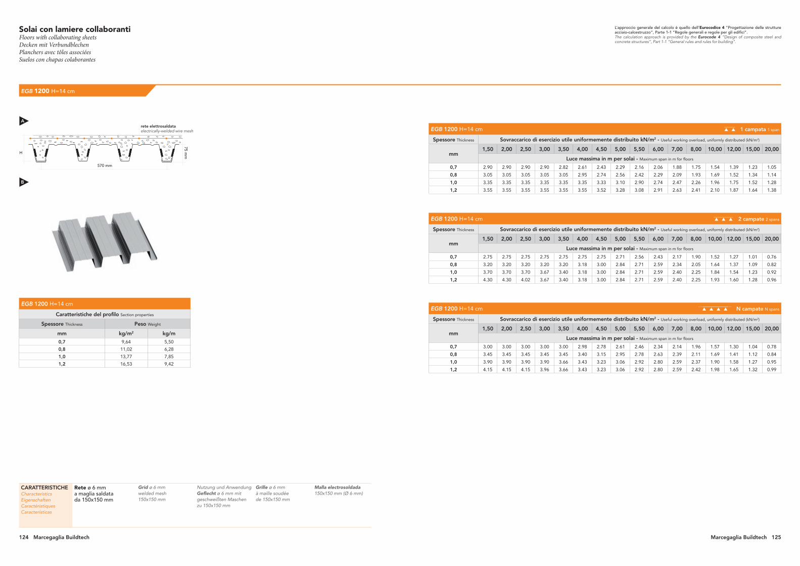
124 Marcegaglia Buildtech Marcegaglia Buildtech 125
EGB 1200 H=14 cm
EGB 1200 H=14 cm 1 campata 1 span
Spessore Thickness Sovraccarico di esercizio utile uniformemente distribuito kN/m2 - Useful working overload, uniformly distributed (kN/m2)
mm 1,50 2,00 2,50 3,00 3,50 4,00 4,50 5,00 5,50 6,00 7,00 8,00 10,00 12,00 15,00 20,00
Luce massima in m per solai - Maximum span in m for floors
0,7 2.90 2.90 2.90 2.90 2.82 2.61 2.43 2.29 2.16 2.06 1.88 1.75 1.54 1.39 1.23 1.05
0,8 3.05 3.05 3.05 3.05 3.05 2.95 2.74 2.56 2.42 2.29 2.09 1.93 1.69 1.52 1.34 1.14
1,0 3.35 3.35 3.35 3.35 3.35 3.35 3.33 3.10 2.90 2.74 2.47 2.26 1.96 1.75 1.52 1.28
1,2 3.55 3.55 3.55 3.55 3.55 3.55 3.52 3.28 3.08 2.91 2.63 2.41 2.10 1.87 1.64 1.38
EGB 1200 H=14 cm 2 campate 2 spans
Spessore Thickness Sovraccarico di esercizio utile uniformemente distribuito kN/m2 - Useful working overload, uniformly distributed (kN/m2)
mm 1,50 2,00 2,50 3,00 3,50 4,00 4,50 5,00 5,50 6,00 7,00 8,00 10,00 12,00 15,00 20,00
Luce massima in m per solai - Maximum span in m for floors
0,7 2.75 2.75 2.75 2.75 2.75 2.75 2.75 2.71 2.56 2.43 2.17 1.90 1.52 1.27 1.01 0.76
0,8 3.20 3.20 3.20 3.20 3.20 3.18 3.00 2.84 2.71 2.59 2.34 2.05 1.64 1.37 1.09 0.82
1,0 3.70 3.70 3.70 3.67 3.40 3.18 3.00 2.84 2.71 2.59 2.40 2.25 1.84 1.54 1.23 0.92
1,2 4.30 4.30 4.02 3.67 3.40 3.18 3.00 2.84 2.71 2.59 2.40 2.25 1.93 1.60 1.28 0.96
EGB 1200 H=14 cm N campate N spans
Spessore Thickness Sovraccarico di esercizio utile uniformemente distribuito kN/m2 - Useful working overload, uniformly distributed (kN/m2)
mm 1,50 2,00 2,50 3,00 3,50 4,00 4,50 5,00 5,50 6,00 7,00 8,00 10,00 12,00 15,00 20,00
Luce massima in m per solai - Maximum span in m for floors
0,7 3.00 3.00 3.00 3.00 3.00 2.98 2.78 2.61 2.46 2.34 2.14 1.96 1.57 1.30 1.04 0.78
0,8 3.45 3.45 3.45 3.45 3.45 3.40 3.15 2.95 2.78 2.63 2.39 2.11 1.69 1.41 1.12 0.84
1,0 3.90 3.90 3.90 3.90 3.66 3.43 3.23 3.06 2.92 2.80 2.59 2.37 1.90 1.58 1.27 0.95
1,2 4.15 4.15 4.15 3.96 3.66 3.43 3.23 3.06 2.92 2.80 2.59 2.42 1.98 1.65 1.32 0.99
L’approccio generale del calcolo è quello dell’Eurocodice 4 “Progettazione delle strutture acciaio-calcestruzzo”, Parte 1-1 “Regole generali e regole per gli edifici”.The calculation approach is provided by the Eurocode 4 “Design of composite steel and concrete structures”, Part 1-1 “General rules and rules for building”.
EGB 1200 H=14 cm
Caratteristiche del profilo Section properties
Spessore Thickness Peso Weight
mm kg/m2 kg/m
0,7 9,64 5,50
0,8 11,02 6,28
1,0 13,77 7,85
1,2 16,53 9,42
H
570 mm
75 mm
CARATTERISTICHECharacteristicsEigenschaftenCaractéristiquesCaracterísticas
Rete ø 6 mma maglia saldata da 150x150 mm
Grid ø 6 mm welded mesh 150x150 mm
Nutzung und Anwendung Geflecht ø 6 mm mit geschweißten Maschen zu 150x150 mm
Grille ø 6 mm à maille soudée de 150x150 mm
Malla electrosoldada 150x150 mm (Ø 6 mm)
rete elettrosaldataelectrically-welded wire mesh
A
B
Solai con lamiere collaborantiFloors with collaborating sheetsDecken mit VerbundblechenPlanchers avec tôles associées Suelos con chapas colaborantes

126 Marcegaglia Buildtech Marcegaglia Buildtech 127
EGB 1200 H=15 cm
EGB 1200 H=15 cm 1 campata 1 span
Spessore Thickness Sovraccarico di esercizio utile uniformemente distribuito kN/m2 - Useful working overload, uniformly distributed (kN/m2)
mm 1,50 2,00 2,50 3,00 3,50 4,00 4,50 5,00 5,50 6,00 7,00 8,00 10,00 12,00 15,00 20,00
Luce massima in m per solai - Maximum span in m for floors
0,7 2.80 2.80 2.80 2.80 2.80 2.77 2.58 2.43 2.30 2.18 2.00 1.85 1.63 1.47 1.30 1.11
0,8 2.95 2.95 2.95 2.95 2.95 2.95 2.92 2.73 2.58 2.44 2.22 2.05 1.79 1.61 1.42 1.20
1,0 3.20 3.20 3.20 3.20 3.20 3.20 3.20 3.20 3.11 2.93 2.64 2.42 2.09 1.87 1.62 1.36
1,2 3.45 3.45 3.45 3.45 3.45 3.45 3.45 3.45 3.30 3.11 2.81 2.58 2.24 2.00 1.74 1.47
EGB 1200 H=15 cm 2 campate 2 spans
Spessore Thickness Sovraccarico di esercizio utile uniformemente distribuito kN/m2 - Useful working overload, uniformly distributed (kN/m2)
mm 1,50 2,00 2,50 3,00 3,50 4,00 4,50 5,00 5,50 6,00 7,00 8,00 10,00 12,00 15,00 20,00
Luce massima in m per solai - Maximum span in m for floors
0,7 2.60 2.60 2.60 2.60 2.60 2.60 2.60 2.60 2.60 2.58 2.33 2.04 1.63 1.36 1.09 0.81
0,8 3.00 3.00 3.00 3.00 3.00 3.00 3.00 2.98 2.84 2.72 2.51 2.19 1.75 1.46 1.17 0.88
1,0 3.50 3.50 3.50 3.50 3.50 3.33 3.14 2.98 2.84 2.72 2.52 2.35 1.97 1.65 1.32 0.99
1,2 4.10 4.10 4.10 3.84 3.56 3.33 3.14 2.98 2.84 2.72 2.52 2.35 2.06 1.72 1.37 1.03
EGB 1200 H=15 cm N campate N spans
Spessore Thickness Sovraccarico di esercizio utile uniformemente distribuito kN/m2 - Useful working overload, uniformly distributed (kN/m2)
mm 1,50 2,00 2,50 3,00 3,50 4,00 4,50 5,00 5,50 6,00 7,00 8,00 10,00 12,00 15,00 20,00
Luce massima in m per solai - Maximum span in m for floors
0,7 2.80 2.80 2.80 2.80 2.80 2.80 2.80 2.77 2.62 2.49 2.27 2.10 1.68 1.40 1.12 0.84
0,8 3.25 3.25 3.25 3.25 3.25 3.25 3.25 3.15 2.96 2.80 2.55 2.26 1.81 1.51 1.20 0.90
1,0 3.80 3.80 3.80 3.80 3.80 3.59 3.38 3.21 3.06 2.93 2.71 2.54 2.03 1.69 1.36 1.02
1,2 4.10 4.10 4.10 4.10 3.84 3.59 3.38 3.21 3.06 2.93 2.71 2.54 2.12 1.77 1.41 1.06
L’approccio generale del calcolo è quello dell’Eurocodice 4 “Progettazione delle strutture acciaio-calcestruzzo”, Parte 1-1 “Regole generali e regole per gli edifici”.The calculation approach is provided by the Eurocode 4 “Design of composite steel and concrete structures”, Part 1-1 “General rules and rules for building”.
EGB 1200 H=15 cm
Caratteristiche del profilo Section properties
Spessore Thickness Peso Weight
mm kg/m2 kg/m
0,7 9,64 5,50
0,8 11,02 6,28
1,0 13,77 7,85
1,2 16,53 9,42
H
570 mm
75 mm
CARATTERISTICHECharacteristicsEigenschaftenCaractéristiquesCaracterísticas
Rete ø 6 mma maglia saldata da 150x150 mm
Grid ø 6 mm welded mesh 150x150 mm
Nutzung und Anwendung Geflecht ø 6 mm mit geschweißten Maschen zu 150x150 mm
Grille ø 6 mm à maille soudée de 150x150 mm
Malla electrosoldada 150x150 mm (Ø 6 mm)
rete elettrosaldataelectrically-welded wire mesh
A
B
Solai con lamiere collaborantiFloors with collaborating sheetsDecken mit VerbundblechenPlanchers avec tôles associées Suelos con chapas colaborantes

Solai con lamiere collaboranti con puntellazioni e armatura al negativoFloors with collaborating plates with struts and negative reinforcementSohlen mit verbundenen Blechen mit Stützen und negativem GerüstPlanchers avec des tôles collaborant avec étançonnements et armature au négatifSuelos con planchas colaborantes con apuntalaciones y armadura al negativo
EGB 210 H=10 cm
EGB 210 H=10 cm 1 campata 1 span
Spessore Thickness Sovraccarico di esercizio utile uniformemente distribuito kN/m2 - Useful working overload, uniformly distributed (kN/m2)
mm 1,50 2,00 2,50 3,00 3,50 4,00 4,50 5,00 5,50 6,00 7,00 8,00 10,00 12,00 15,00 20,00
Luce massima in m per solai - Maximum span in m for floors
0,7 5.50 4.60 3.89 3.40 3.04 2.77 2.55 2.37 2.22 2.09 1.89 1.73 1.50 1.34 1.17 0.98
0,8 5.94 4.78 4.06 3.57 3.20 2.92 2.70 2.52 2.36 2.23 2.02 1.86 1.61 1.44 1.26 1.06
1,0 6.09 5.17 4.43 3.92 3.54 3.24 3.00 2.81 2.65 2.51 2.28 2.10 1.84 1.65 1.45 1.23
1,2 6.21 5.47 4.70 4.17 3.77 3.46 3.21 3.01 2.83 2.69 2.45 2.26 1.98 1.78 1.56 1.33
EGB 210 H=10 cm 2 campate 2 spans
Spessore Thickness Sovraccarico di esercizio utile uniformemente distribuito kN/m2 - Useful working overload, uniformly distributed (kN/m2)
mm 1,50 2,00 2,50 3,00 3,50 4,00 4,50 5,00 5,50 6,00 7,00 8,00 10,00 12,00 15,00 20,00
Luce massima in m per solai - Maximum span in m for floors
0,7 5.75 5.58 4.83 4.21 3.75 3.40 3.12 2.90 2.71 2.55 2.29 2.09 1.81 1.61 1.33 1.00
0,8 6.05 5.58 4.99 4.39 3.92 3.57 3.29 3.06 2.86 2.70 2.44 2.23 1.93 1.72 1.47 1.10
1,0 6.44 5.58 4.99 4.55 4.22 3.92 3.62 3.38 3.18 3.00 2.72 2.51 2.18 1.95 1.61 1.21
1,2 6.44 5.58 4.99 4.55 4.22 3.94 3.72 3.53 3.36 3.21 2.92 2.69 2.35 2.10 1.73 1.30
EGB 210 H=10 cm N campate N spans
Spessore Thickness Sovraccarico di esercizio utile uniformemente distribuito kN/m2 - Useful working overload, uniformly distributed (kN/m2)
mm 1,50 2,00 2,50 3,00 3,50 4,00 4,50 5,00 5,50 6,00 7,00 8,00 10,00 12,00 15,00 20,00
Luce massima in m per solai - Maximum span in m for floors
0,7 5.70 5.47 4.60 4.01 3.57 3.24 2.98 2.77 2.59 2.44 2.19 2.01 1.73 1.54 1.34 1.02
0,8 6.00 5.66 4.78 4.19 3.75 3.41 3.14 2.92 2.74 2.59 2.33 2.14 1.86 1.65 1.44 1.14
1,0 6.45 6.01 5.17 4.55 4.10 3.75 3.47 3.24 3.05 2.88 2.62 2.41 2.10 1.88 1.65 1.24
1,2 6.80 6.01 5.38 4.83 4.36 3.99 3.70 3.46 3.26 3.08 2.80 2.58 2.26 2.03 1.78 1.33
CARATTERISTICHECharacteristicsEigenschaftenCaractéristiquesCaracterísticas
Rete ø 6 mma maglia saldata da 150x150 mm
Tondino di rinforzoø 8 mm
Grid ø 6 mm welded mesh 150x150 mm
Reinforcement bar ø 8 mm
Nutzung und Anwendung Geflecht ø 6 mm mit geschweißten Maschen zu 150x150 mm
Rundstab zur Verstärkung ø 8 mm
Grille ø 6 mm à maille soudée de 150x150 mm
Rond à béton de renforcement ø 8 mm
Malla electrosoldada 150x150 mm (Ø 6 mm)
Barra de refuerzo ø 8 mm
L’approccio generale del calcolo è quello dell’Eurocodice 4 “Progettazione delle strutture acciaio-calcestruzzo”, Parte 1-1 “Regole generali e regole per gli edifici”.The calculation approach is provided by the Eurocode 4 “Design of composite steel and concrete structures”, Part 1-1 “General rules and rules for building”.
EGB 210 H=10 cm
Caratteristiche del profilo Section properties
Spessore Thickness Peso Weight
Peso Weight
1000 1250
mm kg/m2 kg/m
0,7 9,16 5,50 6,87
0,8 10,47 6,28 7,85
1,0 13,08 7,85 9,81
1,2 15,70 9,42 11,78
1000 mm1250 mm
600 mm750 mm
sviluppo nastrostrip width
tondinobar
larghezza utilecoverage{ {
H
600 mm
55 mm
rete elettrosaldataelectrically-welded wire mesh
A
B
128 Marcegaglia Buildtech Marcegaglia Buildtech 129
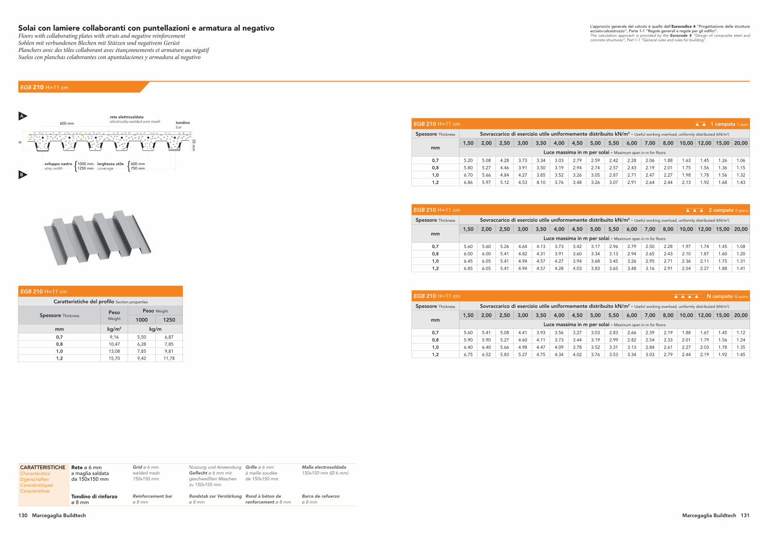
Solai con lamiere collaboranti con puntellazioni e armatura al negativoFloors with collaborating plates with struts and negative reinforcementSohlen mit verbundenen Blechen mit Stützen und negativem GerüstPlanchers avec des tôles collaborant avec étançonnements et armature au négatifSuelos con planchas colaborantes con apuntalaciones y armadura al negativo
EGB 210 H=11 cm
EGB 210 H=11 cm 1 campata 1 span
Spessore Thickness Sovraccarico di esercizio utile uniformemente distribuito kN/m2 - Useful working overload, uniformly distributed (kN/m2)
mm 1,50 2,00 2,50 3,00 3,50 4,00 4,50 5,00 5,50 6,00 7,00 8,00 10,00 12,00 15,00 20,00
Luce massima in m per solai - Maximum span in m for floors
0,7 5.20 5.08 4.28 3.73 3.34 3.03 2.79 2.59 2.42 2.28 2.06 1.88 1.63 1.45 1.26 1.06
0,8 5.80 5.27 4.46 3.91 3.50 3.19 2.94 2.74 2.57 2.43 2.19 2.01 1.75 1.56 1.36 1.15
1,0 6.70 5.66 4.84 4.27 3.85 3.52 3.26 3.05 2.87 2.71 2.47 2.27 1.98 1.78 1.56 1.32
1,2 6.86 5.97 5.12 4.53 4.10 3.76 3.48 3.26 3.07 2.91 2.64 2.44 2.13 1.92 1.68 1.43
EGB 210 H=11 cm 2 campate 2 spans
Spessore Thickness Sovraccarico di esercizio utile uniformemente distribuito kN/m2 - Useful working overload, uniformly distributed (kN/m2)
mm 1,50 2,00 2,50 3,00 3,50 4,00 4,50 5,00 5,50 6,00 7,00 8,00 10,00 12,00 15,00 20,00
Luce massima in m per solai - Maximum span in m for floors
0,7 5.60 5.60 5.26 4.64 4.13 3.73 3.42 3.17 2.96 2.79 2.50 2.28 1.97 1.74 1.45 1.08
0,8 6.00 6.00 5.41 4.82 4.31 3.91 3.60 3.34 3.13 2.94 2.65 2.43 2.10 1.87 1.60 1.20
1,0 6.45 6.05 5.41 4.94 4.57 4.27 3.94 3.68 3.45 3.26 2.95 2.71 2.36 2.11 1.75 1.31
1,2 6.85 6.05 5.41 4.94 4.57 4.28 4.03 3.83 3.65 3.48 3.16 2.91 2.54 2.27 1.88 1.41
EGB 210 H=11 cm N campate N spans
Spessore Thickness Sovraccarico di esercizio utile uniformemente distribuito kN/m2 - Useful working overload, uniformly distributed (kN/m2)
mm 1,50 2,00 2,50 3,00 3,50 4,00 4,50 5,00 5,50 6,00 7,00 8,00 10,00 12,00 15,00 20,00
Luce massima in m per solai - Maximum span in m for floors
0,7 5.60 5.41 5.08 4.41 3.93 3.56 3.27 3.03 2.83 2.66 2.39 2.19 1.88 1.67 1.45 1.12
0,8 5.90 5.90 5.27 4.60 4.11 3.73 3.44 3.19 2.99 2.82 2.54 2.33 2.01 1.79 1.56 1.24
1,0 6.40 6.40 5.66 4.98 4.47 4.09 3.78 3.52 3.31 3.13 2.84 2.61 2.27 2.03 1.78 1.35
1,2 6.75 6.52 5.83 5.27 4.75 4.34 4.02 3.76 3.53 3.34 3.03 2.79 2.44 2.19 1.92 1.45
L’approccio generale del calcolo è quello dell’Eurocodice 4 “Progettazione delle strutture acciaio-calcestruzzo”, Parte 1-1 “Regole generali e regole per gli edifici”.The calculation approach is provided by the Eurocode 4 “Design of composite steel and concrete structures”, Part 1-1 “General rules and rules for building”.
EGB 210 H=11 cm
Caratteristiche del profilo Section properties
Spessore Thickness Peso Weight
Peso Weight
1000 1250
mm kg/m2 kg/m
0,7 9,16 5,50 6,87
0,8 10,47 6,28 7,85
1,0 13,08 7,85 9,81
1,2 15,70 9,42 11,78
1000 mm1250 mm
600 mm750 mm
sviluppo nastrostrip width
tondinobar
larghezza utilecoverage{ {
H
600 mm
55 mm
rete elettrosaldataelectrically-welded wire mesh
CARATTERISTICHECharacteristicsEigenschaftenCaractéristiquesCaracterísticas
Rete ø 6 mma maglia saldata da 150x150 mm
Tondino di rinforzoø 8 mm
Grid ø 6 mm welded mesh 150x150 mm
Reinforcement bar ø 8 mm
Nutzung und Anwendung Geflecht ø 6 mm mit geschweißten Maschen zu 150x150 mm
Rundstab zur Verstärkung ø 8 mm
Grille ø 6 mm à maille soudée de 150x150 mm
Rond à béton de renforcement ø 8 mm
Malla electrosoldada 150x150 mm (Ø 6 mm)
Barra de refuerzo ø 8 mm
A
B
130 Marcegaglia Buildtech Marcegaglia Buildtech 131

Solai con lamiere collaboranti con puntellazioni e armatura al negativoFloors with collaborating plates with struts and negative reinforcementSohlen mit verbundenen Blechen mit Stützen und negativem GerüstPlanchers avec des tôles collaborant avec étançonnements et armature au négatifSuelos con planchas colaborantes con apuntalaciones y armadura al negativo
EGB 210 H=12 cm
EGB 210 H=12 cm 1 campata 1 span
Spessore Thickness Sovraccarico di esercizio utile uniformemente distribuito kN/m2 - Useful working overload, uniformly distributed (kN/m2)
mm 1,50 2,00 2,50 3,00 3,50 4,00 4,50 5,00 5,50 6,00 7,00 8,00 10,00 12,00 15,00 20,00
Luce massima in m per solai - Maximum span in m for floors
0,7 4.90 4.90 4.67 4.06 3.62 3.29 3.02 2.80 2.62 2.47 2.22 2.03 1.75 1.56 1.35 1.13
0,8 5.50 5.50 4.85 4.24 3.80 3.46 3.18 2.96 2.78 2.62 2.36 2.17 1.88 1.67 1.46 1.23
1,0 6.45 6.13 5.23 4.61 4.15 3.79 3.51 3.28 3.08 2.91 2.64 2.43 2.12 1.90 1.66 1.41
1,2 7.10 6.46 5.53 4.88 4.41 4.04 3.74 3.50 3.29 3.12 2.83 2.61 2.28 2.04 1.79 1.52
EGB 210 H=12 cm 2 campate 2 spans
Spessore Thickness Sovraccarico di esercizio utile uniformemente distribuito kN/m2 - Useful working overload, uniformly distributed (kN/m2)
mm 1,50 2,00 2,50 3,00 3,50 4,00 4,50 5,00 5,50 6,00 7,00 8,00 10,00 12,00 15,00 20,00
Luce massima in m per solai - Maximum span in m for floors
0,7 5.30 5.30 5.30 5.06 4.50 4.06 3.72 3.45 3.22 3.02 2.71 2.47 2.12 1.88 1.56 1.17
0,8 5.90 5.90 5.80 5.25 4.68 4.24 3.90 3.62 3.38 3.18 2.87 2.62 2.26 2.01 1.73 1.30
1,0 6.40 6.40 5.80 5.29 4.90 4.59 4.25 3.96 3.72 3.51 3.17 2.91 2.53 2.26 1.89 1.42
1,2 6.80 6.48 5.80 5.29 4.90 4.59 4.32 4.10 3.91 3.74 3.39 3.12 2.71 2.43 2.03 1.52
EGB 210 H=12 cm N campate N spans
Spessore Thickness Sovraccarico di esercizio utile uniformemente distribuito kN/m2 - Useful working overload, uniformly distributed (kN/m2)
mm 1,50 2,00 2,50 3,00 3,50 4,00 4,50 5,00 5,50 6,00 7,00 8,00 10,00 12,00 15,00 20,00
Luce massima in m per solai - Maximum span in m for floors
0,7 5.30 5.30 5.30 4.82 4.28 3.87 3.55 3.29 3.07 2.89 2.59 2.36 2.03 1.80 1.56 1.20
0,8 5.85 5.85 5.74 5.00 4.46 4.05 3.72 3.46 3.23 3.05 2.74 2.51 2.17 1.93 1.67 1.34
1,0 6.35 6.35 6.13 5.38 4.83 4.41 4.07 3.79 3.56 3.36 3.04 2.80 2.43 2.17 1.90 1.46
1,2 6.70 6.70 6.25 5.69 5.12 4.68 4.33 4.04 3.79 3.59 3.25 2.99 2.61 2.34 2.04 1.57
L’approccio generale del calcolo è quello dell’Eurocodice 4 “Progettazione delle strutture acciaio-calcestruzzo”, Parte 1-1 “Regole generali e regole per gli edifici”.The calculation approach is provided by the Eurocode 4 “Design of composite steel and concrete structures”, Part 1-1 “General rules and rules for building”.
EGB 210 H=12 cm
Caratteristiche del profilo Section properties
Spessore Thickness Peso Weight
Peso Weight
1000 1250
mm kg/m2 kg/m
0,7 9,16 5,50 6,87
0,8 10,47 6,28 7,85
1,0 13,08 7,85 9,81
1,2 15,70 9,42 11,78
1000 mm1250 mm
600 mm750 mm
sviluppo nastrostrip width
tondinobar
larghezza utilecoverage{ {
H
600 mm
55 mm
rete elettrosaldataelectrically-welded wire mesh
CARATTERISTICHECharacteristicsEigenschaftenCaractéristiquesCaracterísticas
Rete ø 6 mma maglia saldata da 150x150 mm
Tondino di rinforzoø 8 mm
Grid ø 6 mm welded mesh 150x150 mm
Reinforcement bar ø 8 mm
Nutzung und Anwendung Geflecht ø 6 mm mit geschweißten Maschen zu 150x150 mm
Rundstab zur Verstärkung ø 8 mm
Grille ø 6 mm à maille soudée de 150x150 mm
Rond à béton de renforcement ø 8 mm
Malla electrosoldada 150x150 mm (Ø 6 mm)
Barra de refuerzo ø 8 mm
A
B
132 Marcegaglia Buildtech Marcegaglia Buildtech 133

Solai con lamiere collaboranti con puntellazioni e armatura al negativoFloors with collaborating plates with struts and negative reinforcementSohlen mit verbundenen Blechen mit Stützen und negativem GerüstPlanchers avec des tôles collaborant avec étançonnements et armature au négatifSuelos con planchas colaborantes con apuntalaciones y armadura al negativo
EGB 1200 H=12 cm
EGB 1200 H=12 cm 1 campata 1 span
Spessore Thickness Sovraccarico di esercizio utile uniformemente distribuito kN/m2 - Useful working overload, uniformly distributed (kN/m2)
mm 1,50 2,00 2,50 3,00 3,50 4,00 4,50 5,00 5,50 6,00 7,00 8,00 10,00 12,00 15,00 20,00
Luce massima in m per solai - Maximum span in m for floors
0,7 4.09 3.42 2.99 2.68 2.44 2.26 2.11 1.99 1.88 1.79 1.64 1.52 1.34 1.22 1.08 0.92
0,8 4.79 3.95 3.41 3.03 2.75 2.53 2.36 2.21 2.09 1.98 1.81 1.67 1.47 1.32 1.17 0.99
1,0 6.21 5.00 4.25 3.73 3.35 3.05 2.82 2.63 2.47 2.33 2.11 1.94 1.68 1.51 1.32 1.09
1,2 6.34 5.25 4.47 3.94 3.54 3.24 3.00 2.80 2.63 2.49 2.25 2.07 1.81 1.62 1.42 1.09
EGB 1200 H=12 cm 2 campate 2 spans
Spessore Thickness Sovraccarico di esercizio utile uniformemente distribuito kN/m2 - Useful working overload, uniformly distributed (kN/m2)
mm 1,50 2,00 2,50 3,00 3,50 4,00 4,50 5,00 5,50 6,00 7,00 8,00 10,00 12,00 15,00 20,00
Luce massima in m per solai - Maximum span in m for floors
0,7 4.92 4.09 3.56 3.18 2.90 2.68 2.50 2.35 2.22 2.11 1.85 1.62 1.29 1.08 0.86 0.65
0,8 5.86 4.79 4.12 3.65 3.30 3.03 2.82 2.64 2.49 2.32 1.99 1.74 1.39 1.16 0.93 0.70
1,0 6.41 5.55 4.96 4.53 4.10 3.73 3.43 3.14 2.85 2.61 2.24 1.96 1.57 1.31 1.05 0.78
1,2 6.41 5.55 4.96 4.53 4.19 3.92 3.63 3.28 2.98 2.73 2.34 2.05 1.64 1.36 1.09 0.82
EGB 1200 H=12 cm N campate N spans
Spessore Thickness Sovraccarico di esercizio utile uniformemente distribuito kN/m2 - Useful working overload, uniformly distributed (kN/m2)
mm 1,50 2,00 2,50 3,00 3,50 4,00 4,50 5,00 5,50 6,00 7,00 8,00 10,00 12,00 15,00 20,00
Luce massima in m per solai - Maximum span in m for floors
0,7 4.72 3.93 3.42 3.06 2.79 2.58 2.40 2.26 2.14 2.03 1.86 1.66 1.33 1.11 0.89 0.67
0,8 5.59 4.59 3.95 3.50 3.17 2.91 2.71 2.53 2.39 2.27 2.05 1.79 1.43 1.20 0.96 0.72
1,0 6.91 5.92 5.00 4.37 3.92 3.56 3.28 3.05 2.86 2.69 2.31 2.02 1.62 1.35 1.08 0.81
1,2 6.91 5.98 5.25 4.60 4.13 3.77 3.48 3.24 3.04 2.81 2.41 2.11 1.69 1.41 1.12 0.84
L’approccio generale del calcolo è quello dell’Eurocodice 4 “Progettazione delle strutture acciaio-calcestruzzo”, Parte 1-1 “Regole generali e regole per gli edifici”.The calculation approach is provided by the Eurocode 4 “Design of composite steel and concrete structures”, Part 1-1 “General rules and rules for building”.
EGB 1200 H=12 cm
Caratteristiche del profilo Section properties
Spessore Thickness Peso Weight
mm kg/m2 kg/m
0,7 9,64 5,50
0,8 11,02 6,28
1,0 13,77 7,85
1,2 16,53 9,42
H
570 mm
75 mm
tondinobar
rete elettrosaldataelectrically-welded wire mesh
CARATTERISTICHECharacteristicsEigenschaftenCaractéristiquesCaracterísticas
Rete ø 6 mma maglia saldata da 150x150 mm
Tondino di rinforzoø 8 mm
Grid ø 6 mm welded mesh 150x150 mm
Reinforcement bar ø 8 mm
Nutzung und Anwendung Geflecht ø 6 mm mit geschweißten Maschen zu 150x150 mm
Rundstab zur Verstärkung ø 8 mm
Grille ø 6 mm à maille soudée de 150x150 mm
Rond à béton de renforcement ø 8 mm
Malla electrosoldada 150x150 mm (Ø 6 mm)
Barra de refuerzo ø 8 mm
A
B
134 Marcegaglia Buildtech Marcegaglia Buildtech 135

Solai con lamiere collaboranti con puntellazioni e armatura al negativoFloors with collaborating plates with struts and negative reinforcementSohlen mit verbundenen Blechen mit Stützen und negativem GerüstPlanchers avec des tôles collaborant avec étançonnements et armature au négatifSuelos con planchas colaborantes con apuntalaciones y armadura al negativo
EGB 1200 H=13 cm
EGB 1200 H=13 cm 1 campata 1 span
Spessore Thickness Sovraccarico di esercizio utile uniformemente distribuito kN/m2 - Useful working overload, uniformly distributed (kN/m2)
mm 1,50 2,00 2,50 3,00 3,50 4,00 4,50 5,00 5,50 6,00 7,00 8,00 10,00 12,00 15,00 20,00
Luce massima in m per solai - Maximum span in m for floors
0,7 4.44 3.70 3.23 2.89 2.64 2.44 2.27 2.14 2.03 1.93 1.76 1.64 1.44 1.31 1.16 0.99
0,8 5.24 4.30 3.71 3.29 2.99 2.74 2.55 2.39 2.26 2.14 1.95 1.80 1.58 1.42 1.25 1.07
1,0 6.84 5.51 4.66 4.09 3.66 3.34 3.08 2.87 2.69 2.54 2.29 2.10 1.83 1.63 1.42 1.20
1,2 6.99 5.77 4.90 4.31 3.87 3.53 3.26 3.04 2.86 2.70 2.44 2.25 1.95 1.75 1.53 1.24
EGB 1200 H=13 cm 2 campate 2 spans
Spessore Thickness Sovraccarico di esercizio utile uniformemente distribuito kN/m2 - Useful working overload, uniformly distributed (kN/m2)
mm 1,50 2,00 2,50 3,00 3,50 4,00 4,50 5,00 5,50 6,00 7,00 8,00 10,00 12,00 15,00 20,00
Luce massima in m per solai - Maximum span in m for floors
0,7 5.35 4.44 3.86 3.44 3.13 2.89 2.69 2.53 2.39 2.27 2.01 1.76 1.41 1.17 0.94 0.70
0,8 6.42 5.24 4.49 3.98 3.59 3.29 3.06 2.86 2.69 2.53 2.17 1.90 1.52 1.27 1.01 0.76
1,0 6.88 5.96 5.33 4.87 4.50 4.09 3.76 3.42 3.11 2.85 2.44 2.14 1.71 1.42 1.14 0.85
1,2 6.88 5.96 5.33 4.87 4.50 4.21 3.97 3.57 3.24 2.97 2.55 2.23 1.78 1.49 1.19 0.89
EGB 1200 H=13 cm N campate N spans
Spessore Thickness Sovraccarico di esercizio utile uniformemente distribuito kN/m2 - Useful working overload, uniformly distributed (kN/m2)
mm 1,50 2,00 2,50 3,00 3,50 4,00 4,50 5,00 5,50 6,00 7,00 8,00 10,00 12,00 15,00 20,00
Luce massima in m per solai - Maximum span in m for floors
0,7 5.13 4.26 3.70 3.31 3.01 2.78 2.59 2.44 2.30 2.19 2.00 1.81 1.45 1.21 0.97 0.73
0,8 6.13 5.01 4.30 3.81 3.44 3.16 2.93 2.74 2.59 2.45 2.23 1.95 1.56 1.30 1.04 0.78
1,0 7.42 6.42 5.51 4.81 4.29 3.90 3.59 3.34 3.13 2.93 2.51 2.20 1.76 1.47 1.17 0.88
1,2 7.42 6.42 5.75 5.05 4.52 4.12 3.80 3.53 3.31 3.06 2.62 2.30 1.84 1.53 1.22 0.92
L’approccio generale del calcolo è quello dell’Eurocodice 4 “Progettazione delle strutture acciaio-calcestruzzo”, Parte 1-1 “Regole generali e regole per gli edifici”.The calculation approach is provided by the Eurocode 4 “Design of composite steel and concrete structures”, Part 1-1 “General rules and rules for building”.
EGB 1200 H=13 cm
Caratteristiche del profilo Section properties
Spessore Thickness Peso Weight
mm kg/m2 kg/m
0,7 9,64 5,50
0,8 11,02 6,28
1,0 13,77 7,85
1,2 16,53 9,42
H
570 mm
75 mm
tondinobar
rete elettrosaldataelectrically-welded wire mesh
CARATTERISTICHECharacteristicsEigenschaftenCaractéristiquesCaracterísticas
Rete ø 6 mma maglia saldata da 150x150 mm
Tondino di rinforzoø 8 mm
Grid ø 6 mm welded mesh 150x150 mm
Reinforcement bar ø 8 mm
Nutzung und Anwendung Geflecht ø 6 mm mit geschweißten Maschen zu 150x150 mm
Rundstab zur Verstärkung ø 8 mm
Grille ø 6 mm à maille soudée de 150x150 mm
Rond à béton de renforcement ø 8 mm
Malla electrosoldada 150x150 mm (Ø 6 mm)
Barra de refuerzo ø 8 mm
A
B
136 Marcegaglia Buildtech Marcegaglia Buildtech 137
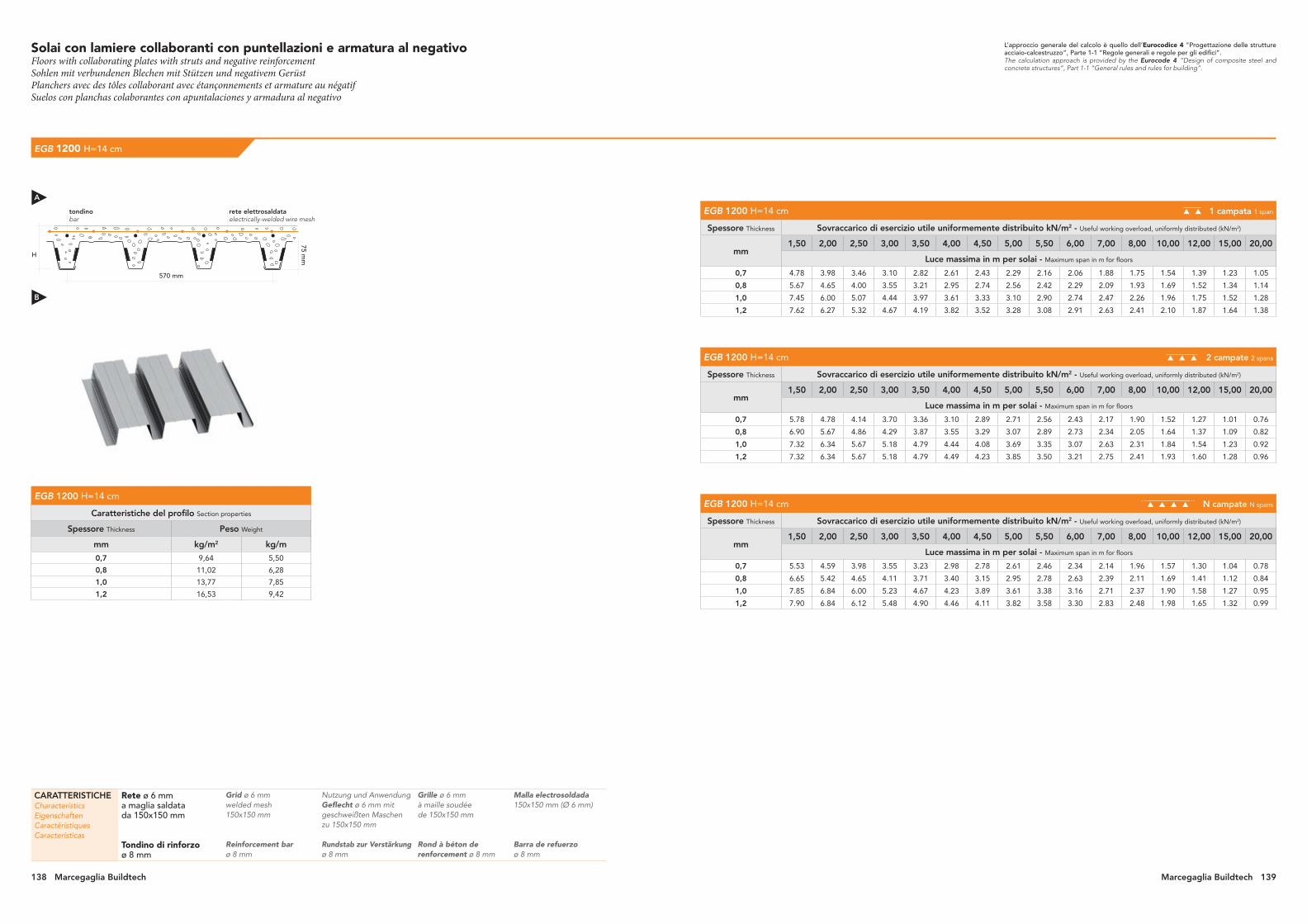
Solai con lamiere collaboranti con puntellazioni e armatura al negativoFloors with collaborating plates with struts and negative reinforcementSohlen mit verbundenen Blechen mit Stützen und negativem GerüstPlanchers avec des tôles collaborant avec étançonnements et armature au négatifSuelos con planchas colaborantes con apuntalaciones y armadura al negativo
EGB 1200 H=14 cm
EGB 1200 H=14 cm 1 campata 1 span
Spessore Thickness Sovraccarico di esercizio utile uniformemente distribuito kN/m2 - Useful working overload, uniformly distributed (kN/m2)
mm 1,50 2,00 2,50 3,00 3,50 4,00 4,50 5,00 5,50 6,00 7,00 8,00 10,00 12,00 15,00 20,00
Luce massima in m per solai - Maximum span in m for floors
0,7 4.78 3.98 3.46 3.10 2.82 2.61 2.43 2.29 2.16 2.06 1.88 1.75 1.54 1.39 1.23 1.05
0,8 5.67 4.65 4.00 3.55 3.21 2.95 2.74 2.56 2.42 2.29 2.09 1.93 1.69 1.52 1.34 1.14
1,0 7.45 6.00 5.07 4.44 3.97 3.61 3.33 3.10 2.90 2.74 2.47 2.26 1.96 1.75 1.52 1.28
1,2 7.62 6.27 5.32 4.67 4.19 3.82 3.52 3.28 3.08 2.91 2.63 2.41 2.10 1.87 1.64 1.38
EGB 1200 H=14 cm 2 campate 2 spans
Spessore Thickness Sovraccarico di esercizio utile uniformemente distribuito kN/m2 - Useful working overload, uniformly distributed (kN/m2)
mm 1,50 2,00 2,50 3,00 3,50 4,00 4,50 5,00 5,50 6,00 7,00 8,00 10,00 12,00 15,00 20,00
Luce massima in m per solai - Maximum span in m for floors
0,7 5.78 4.78 4.14 3.70 3.36 3.10 2.89 2.71 2.56 2.43 2.17 1.90 1.52 1.27 1.01 0.76
0,8 6.90 5.67 4.86 4.29 3.87 3.55 3.29 3.07 2.89 2.73 2.34 2.05 1.64 1.37 1.09 0.82
1,0 7.32 6.34 5.67 5.18 4.79 4.44 4.08 3.69 3.35 3.07 2.63 2.31 1.84 1.54 1.23 0.92
1,2 7.32 6.34 5.67 5.18 4.79 4.49 4.23 3.85 3.50 3.21 2.75 2.41 1.93 1.60 1.28 0.96
EGB 1200 H=14 cm N campate N spans
Spessore Thickness Sovraccarico di esercizio utile uniformemente distribuito kN/m2 - Useful working overload, uniformly distributed (kN/m2)
mm 1,50 2,00 2,50 3,00 3,50 4,00 4,50 5,00 5,50 6,00 7,00 8,00 10,00 12,00 15,00 20,00
Luce massima in m per solai - Maximum span in m for floors
0,7 5.53 4.59 3.98 3.55 3.23 2.98 2.78 2.61 2.46 2.34 2.14 1.96 1.57 1.30 1.04 0.78
0,8 6.65 5.42 4.65 4.11 3.71 3.40 3.15 2.95 2.78 2.63 2.39 2.11 1.69 1.41 1.12 0.84
1,0 7.85 6.84 6.00 5.23 4.67 4.23 3.89 3.61 3.38 3.16 2.71 2.37 1.90 1.58 1.27 0.95
1,2 7.90 6.84 6.12 5.48 4.90 4.46 4.11 3.82 3.58 3.30 2.83 2.48 1.98 1.65 1.32 0.99
L’approccio generale del calcolo è quello dell’Eurocodice 4 “Progettazione delle strutture acciaio-calcestruzzo”, Parte 1-1 “Regole generali e regole per gli edifici”.The calculation approach is provided by the Eurocode 4 “Design of composite steel and concrete structures”, Part 1-1 “General rules and rules for building”.
EGB 1200 H=14 cm
Caratteristiche del profilo Section properties
Spessore Thickness Peso Weight
mm kg/m2 kg/m
0,7 9,64 5,50
0,8 11,02 6,28
1,0 13,77 7,85
1,2 16,53 9,42
H
570 mm
75 mm
tondinobar
rete elettrosaldataelectrically-welded wire mesh
CARATTERISTICHECharacteristicsEigenschaftenCaractéristiquesCaracterísticas
Rete ø 6 mma maglia saldata da 150x150 mm
Tondino di rinforzoø 8 mm
Grid ø 6 mm welded mesh 150x150 mm
Reinforcement bar ø 8 mm
Nutzung und Anwendung Geflecht ø 6 mm mit geschweißten Maschen zu 150x150 mm
Rundstab zur Verstärkung ø 8 mm
Grille ø 6 mm à maille soudée de 150x150 mm
Rond à béton de renforcement ø 8 mm
Malla electrosoldada 150x150 mm (Ø 6 mm)
Barra de refuerzo ø 8 mm
A
B
138 Marcegaglia Buildtech Marcegaglia Buildtech 139

Solai con lamiere collaboranti con puntellazioni e armatura al negativoFloors with collaborating plates with struts and negative reinforcementSohlen mit verbundenen Blechen mit Stützen und negativem GerüstPlanchers avec des tôles collaborant avec étançonnements et armature au négatifSuelos con planchas colaborantes con apuntalaciones y armadura al negativo
EGB 1200 H=15 cm
EGB 1200 H=15 cm 1 campata 1 span
Spessore Thickness Sovraccarico di esercizio utile uniformemente distribuito kN/m2 - Useful working overload, uniformly distributed (kN/m2)
mm 1,50 2,00 2,50 3,00 3,50 4,00 4,50 5,00 5,50 6,00 7,00 8,00 10,00 12,00 15,00 20,00
Luce massima in m per solai - Maximum span in m for floors
0,7 5.11 4.25 3.69 3.30 3.00 2.77 2.58 2.43 2.30 2.18 2.00 1.85 1.63 1.47 1.30 1.11
0,8 6.05 4.98 4.28 3.79 3.43 3.15 2.92 2.73 2.58 2.44 2.22 2.05 1.79 1.61 1.42 1.20
1,0 7.05 6.50 5.48 4.78 4.27 3.88 3.57 3.32 3.11 2.93 2.64 2.42 2.09 1.87 1.62 1.36
1,2 7.97 6.78 5.74 5.02 4.50 4.10 3.78 3.52 3.30 3.11 2.81 2.58 2.24 2.00 1.74 1.47
EGB 1200 H=15 cm 2 campate 2 spans
Spessore Thickness Sovraccarico di esercizio utile uniformemente distribuito kN/m2 - Useful working overload, uniformly distributed (kN/m2)
mm 1,50 2,00 2,50 3,00 3,50 4,00 4,50 5,00 5,50 6,00 7,00 8,00 10,00 12,00 15,00 20,00
Luce massima in m per solai - Maximum span in m for floors
0,7 5.65 5.11 4.42 3.94 3.58 3.30 3.07 2.88 2.72 2.58 2.33 2.04 1.63 1.36 1.09 0.81
0,8 6.55 6.10 5.21 4.60 4.14 3.79 3.51 3.28 3.09 2.92 2.51 2.19 1.75 1.46 1.17 0.88
1,0 7.60 6.71 6.00 5.47 5.07 4.74 4.39 3.95 3.59 3.29 2.82 2.47 1.97 1.65 1.32 0.99
1,2 7.74 6.71 6.00 5.47 5.07 4.74 4.47 4.12 3.75 3.44 2.94 2.58 2.06 1.72 1.37 1.03
EGB 1200 H=15 cm N campate N spans
Spessore Thickness Sovraccarico di esercizio utile uniformemente distribuito kN/m2 - Useful working overload, uniformly distributed (kN/m2)
mm 1,50 2,00 2,50 3,00 3,50 4,00 4,50 5,00 5,50 6,00 7,00 8,00 10,00 12,00 15,00 20,00
Luce massima in m per solai - Maximum span in m for floors
0,7 5.65 4.90 4.25 3.79 3.44 3.17 2.95 2.77 2.62 2.49 2.27 2.10 1.68 1.40 1.12 0.84
0,8 6.55 5.83 4.98 4.40 3.97 3.64 3.37 3.15 2.96 2.80 2.55 2.26 1.81 1.51 1.20 0.90
1,0 7.60 7.23 6.47 5.65 5.03 4.56 4.19 3.88 3.63 3.39 2.90 2.54 2.03 1.69 1.36 1.02
1,2 8.25 7.23 6.47 5.90 5.28 4.80 4.41 4.10 3.84 3.54 3.03 2.65 2.12 1.77 1.41 1.06
L’approccio generale del calcolo è quello dell’Eurocodice 4 “Progettazione delle strutture acciaio-calcestruzzo”, Parte 1-1 “Regole generali e regole per gli edifici”.The calculation approach is provided by the Eurocode 4 “Design of composite steel and concrete structures”, Part 1-1 “General rules and rules for building”.
EGB 1200 H=15 cm
Caratteristiche del profilo Section properties
Spessore Thickness Peso Weight
mm kg/m2 kg/m
0,7 9,64 5,50
0,8 11,02 6,28
1,0 13,77 7,85
1,2 16,53 9,42
H
570 mm
75 mm
tondinobar
rete elettrosaldataelectrically-welded wire mesh
CARATTERISTICHECharacteristicsEigenschaftenCaractéristiquesCaracterísticas
Rete ø 6 mma maglia saldata da 150x150 mm
Tondino di rinforzoø 8 mm
Grid ø 6 mm welded mesh 150x150 mm
Reinforcement bar ø 8 mm
Nutzung und Anwendung Geflecht ø 6 mm mit geschweißten Maschen zu 150x150 mm
Rundstab zur Verstärkung ø 8 mm
Grille ø 6 mm à maille soudée de 150x150 mm
Rond à béton de renforcement ø 8 mm
Malla electrosoldada 150x150 mm (Ø 6 mm)
Barra de refuerzo ø 8 mm
A
B
140 Marcegaglia Buildtech Marcegaglia Buildtech 141

Standard solutions for assemblingFlashings - Accessories
IT - EN - DE - FR - ES

1
3
2
3
4
4
5
14
5
72
6
3
8
Tagliare durante il montaggioCut on assembly
Tagliare durante il montaggioCut on assembly
Soluzioni standard per l’assemblaggio di pannelli per copertura e pareteStandard solutions for assembling roofing and wall panelsStandardlösungen für die Montage von Abdeckpaneelen - und WandpaneelenSolutions standard pour l’assemblage de panneaux pour couverture et murSoluciones estándar para el ensamblaje de paneles para cobertura y pared
Giuntura pannello copertura / pannello pareteJoint of roof panel with wall panelVerbindung zwischen Dachpaneel und WandpaneelAssemblage panneau de couverture avec panneau mural Juntura panel de cobertura con panel de pared
1 Pannello copertura Roof panel Dachpaneel Panneau de couverture Panel de cobertura
2 Pannello parete Wall panel Wandpaneel Panneau mural Panel de pared
3 Scossalina Flashing Dichtungsblech Bandeau Perfilado metálico
4 Ribattino a testa fresata Al/Fe o vite autoperforante
Al/Fe single-sided rivet or self-drilling bolt
Al/Fe Senkniete oder selbstschneidende Schraube
Rivet à tête fraisée Al/Fe ou vis autoperforante
Remache de cabeza avellanada Al/Fe o tornillo autoperforante
5 Schiuma di poliuretano o guarnizione di poliuretano
Polyurethane foam or polyurethane gasket
Polyurethanschaum oder Polyurethandichtung
Mousse en polyuréthane ou joint en polyuréthane
Espuma de poliuretano o burlete de poliuretano
Giuntura pannello copertura / pannello pareteJoint of roof panel with wall panelVerbindung zwischen Dachpaneel und WandpaneelAssemblage panneau de couverture avec panneau mural Juntura panel de cobertura con panel de pared
1 Pannello copertura Roof panel Dachpaneel Panneau de couverture Panel de cobertura
2 Pannello parete Wall panel Wandpaneel Panneau mural Panel de pared
3 Scossalina Flashing Dichtungsblech Bandeau Perfilado metálico
4 Scossalina individuale Detailing Einzelnes Dichtungsblech Bandeau individuel Perfilado metálico individual
5 Ribattino a testa fresata Al/Fe o vite autoperforante
Al/Fe single-sided rivet or self-drilling bolt
Al/Fe Senkniete oder selbstschneidende Schraube
Rivet à tête fraisée Al/Fe ou vis autoperforante
Remache de cabeza avellanada Al/Fe o tornillo autoperforante
6 Schiuma di poliuretano Polyurethane foam Polyurethanschaum Mousse en polyuréthane Espuma de poliuretano
7 Giuntura autoperforante Self-drilling connector Selbstschneidende Verbindung Joint autoperforant Juntura autoperforante
8 Elementi di acciaio secondo progetto tecnico
Steel structure in accordance with engineering design
Stahlelement entsprechend technischer Planung
Eléments en acier d’après projet technique
Elementos de acero según proyecto técnico
* simile al * similar to
rosso tegola (RT) tile red
M 4104
avorio chiaro light ivory
RAL 1015 *
grigio ombra umbra grey
RAL 7022 *
grigio antracite anthracite grey
RAL 7016 *
verde reseda reseda green
RAL 6011 *
verde muschio moss green
RAL 6005 *
blu grigiastro grey blue
RAL 5008 *
blu genziana gentian blue
RAL 5010 *
rosso Siena (RS) “Siena” red
M 4301
grigio luce light grey
RAL 7035 *
testa di moro (TM) testa di moro
M 5301
bianco grigio (BG) grey white
M 1301
bianco puropure white
RAL 9010 *
alluminio brillantewhite aluminium
RAL 9006 *
Gamma principali coloriMain colour range Hauptfarbpalette Gamme couleurs principales Gama de colores principales
Coppo siracusano (CS)Coppo siracusano
Coppo anticato scuro (CAS)Coppo antique dark
Coppo anticato chiaro (CAC)Coppo antique light
144 Marcegaglia Buildtech Marcegaglia Buildtech 1
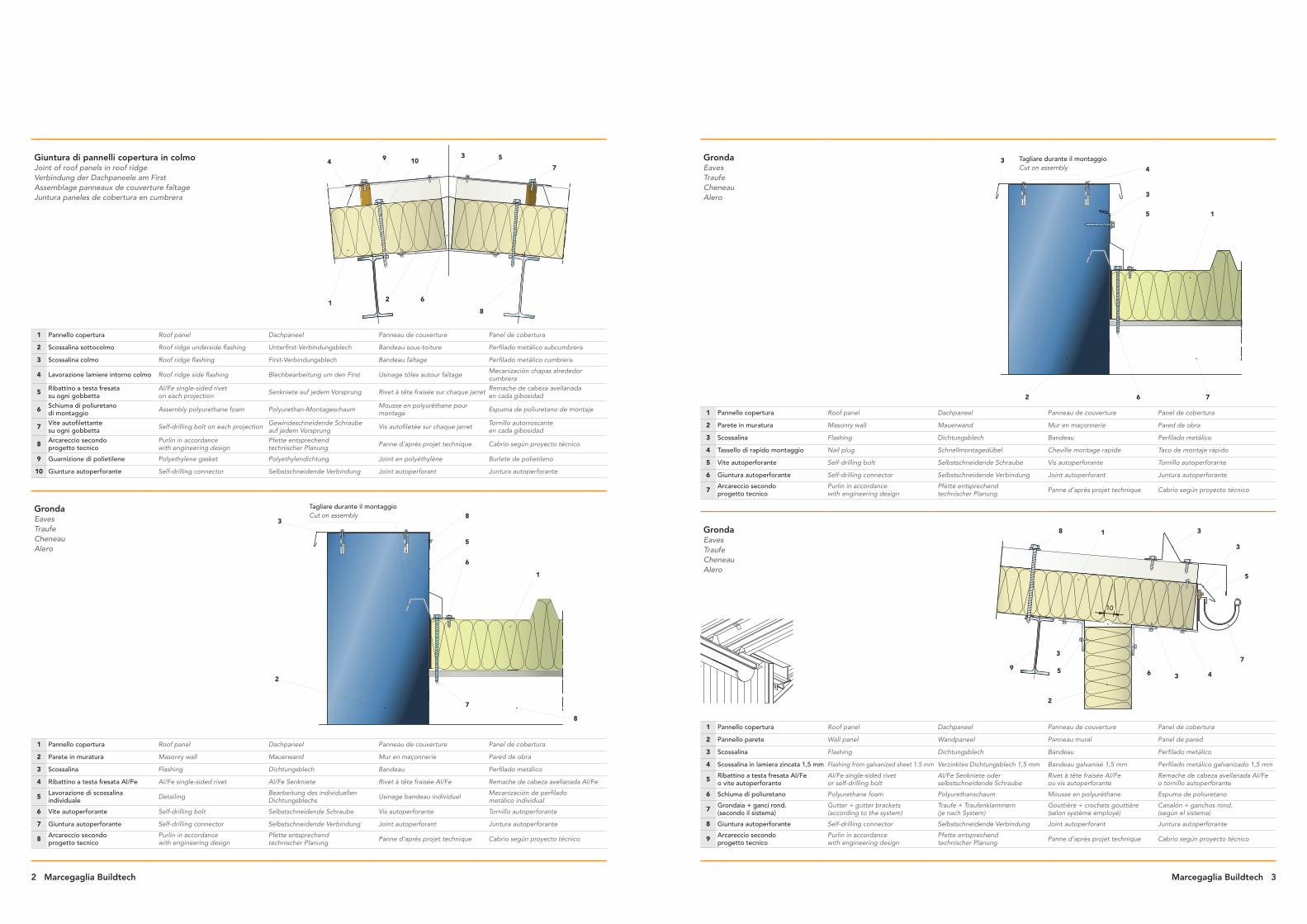
Tagliare durante il montaggioCut on assembly
34
3
5 1
762
8 1 3
3
5
7
4365
2
9
3
10
4
1
9
2
10
8
6
3 5
7
1
6
5
83
2
7
8
Tagliare durante il montaggioCut on assembly
GrondaEaves TraufeCheneauAlero
1 Pannello copertura Roof panel Dachpaneel Panneau de couverture Panel de cobertura
2 Parete in muratura Masonry wall Mauerwand Mur en maçonnerie Pared de obra
3 Scossalina Flashing Dichtungsblech Bandeau Perfilado metálico
4 Tassello di rapido montaggio Nail plug Schnellmontagedübel Cheville montage rapide Taco de montaje rápido
5 Vite autoperforante Self-drilling bolt Selbstschneidende Schraube Vis autoperforante Tornillo autoperforante
6 Giuntura autoperforante Self-drilling connector Selbstschneidende Verbindung Joint autoperforant Juntura autoperforante
7 Arcareccio secondo progetto tecnico
Purlin in accordance with engineering design
Pfette entsprechend technischer Planung Panne d’après projet technique Cabrio según proyecto técnico
GrondaEaves TraufeCheneauAlero
1 Pannello copertura Roof panel Dachpaneel Panneau de couverture Panel de cobertura
2 Pannello parete Wall panel Wandpaneel Panneau mural Panel de pared
3 Scossalina Flashing Dichtungsblech Bandeau Perfilado metálico
4 Scossalina in lamiera zincata 1,5 mm Flashing from galvanized sheet 1.5 mm Verzinktes Dichtungsblech 1,5 mm Bandeau galvanisé 1,5 mm Perfilado metálico galvanizado 1,5 mm
5 Ribattino a testa fresata Al/Fe o vite autoperforante
Al/Fe single-sided rivet or self-drilling bolt
Al/Fe Senkniete oder selbstschneidende Schraube
Rivet à tête fraisée Al/Fe ou vis autoperforante
Remache de cabeza avellanada Al/Fe o tornillo autoperforante
6 Schiuma di poliuretano Polyurethane foam Polyurethanschaum Mousse en polyuréthane Espuma de poliuretano
7 Grondaia + ganci rond. (secondo il sistema)
Gutter + gutter brackets (according to the system)
Traufe + Traufenklammern (je nach System)
Gouttière + crochets gouttière (selon système employé)
Canalón + ganchos rond. (según el sistema)
8 Giuntura autoperforante Self-drilling connector Selbstschneidende Verbindung Joint autoperforant Juntura autoperforante
9 Arcareccio secondo progetto tecnico
Purlin in accordance with engineering design
Pfette entsprechend technischer Planung Panne d’après projet technique Cabrio según proyecto técnico
Giuntura di pannelli copertura in colmo Joint of roof panels in roof ridgeVerbindung der Dachpaneele am FirstAssemblage panneaux de couverture faîtageJuntura paneles de cobertura en cumbrera
1 Pannello copertura Roof panel Dachpaneel Panneau de couverture Panel de cobertura
2 Scossalina sottocolmo Roof ridge underside flashing Unterfirst-Verbindungsblech Bandeau sous-toiture Perfilado metálico subcumbrera
3 Scossalina colmo Roof ridge flashing First-Verbindungsblech Bandeau faîtage Perfilado metálico cumbrera
4 Lavorazione lamiere intorno colmo Roof ridge side flashing Blechbearbeitung um den First Usinage tôles autour faîtage Mecanización chapas alrededor cumbrera
5 Ribattino a testa fresata su ogni gobbetta
Al/Fe single-sided rivet on each projection Senkniete auf jedem Vorsprung Rivet à tête fraisée sur chaque jarret Remache de cabeza avellanada
en cada gibosidad
6 Schiuma di poliuretano di montaggio Assembly polyurethane foam Polyurethan-Montageschaum Mousse en polyuréthane pour
montage Espuma de poliuretano de montaje
7 Vite autofilettante su ogni gobbetta Self-drilling bolt on each projection Gewindeschneidende Schraube
auf jedem Vorsprung Vis autofiletée sur chaque jarret Tornillo autorroscante en cada gibosidad
8 Arcareccio secondo progetto tecnico
Purlin in accordance with engineering design
Pfette entsprechend technischer Planung Panne d’après projet technique Cabrio según proyecto técnico
9 Guarnizione di polietilene Polyethylene gasket Polyethylendichtung Joint en polyéthylène Burlete de polietileno
10 Giuntura autoperforante Self-drilling connector Selbstschneidende Verbindung Joint autoperforant Juntura autoperforante
GrondaEaves TraufeCheneauAlero
1 Pannello copertura Roof panel Dachpaneel Panneau de couverture Panel de cobertura
2 Parete in muratura Masonry wall Mauerwand Mur en maçonnerie Pared de obra
3 Scossalina Flashing Dichtungsblech Bandeau Perfilado metálico
4 Ribattino a testa fresata Al/Fe Al/Fe single-sided rivet Al/Fe Senkniete Rivet à tête fraisée Al/Fe Remache de cabeza avellanada Al/Fe
5 Lavorazione di scossalina individuale Detailing Bearbeitung des individuellen
Dichtungsblechs Usinage bandeau individuel Mecanización de perfilado metálico individual
6 Vite autoperforante Self-drilling bolt Selbstschneidende Schraube Vis autoperforante Tornillo autoperforante
7 Giuntura autoperforante Self-drilling connector Selbstschneidende Verbindung Joint autoperforant Juntura autoperforante
8 Arcareccio secondo progetto tecnico
Purlin in accordance with engineering design
Pfette entsprechend technischer Planung Panne d’après projet technique Cabrio según proyecto técnico
2 Marcegaglia Buildtech Marcegaglia Buildtech 3

1
8
4
3
5
2
6
7
ZoccoloPlinth
1 4
3
5
2
6
ZoccoloPlinth
Intaglio da eseguire durante il montaggio
Make undercut on assembly
~200
Arcareccio allargatoWidened purlin
min. 50 mm min. 50 mm
max. 10 mm
5
4 2
1
3
1
2*
21
3
7
4
6
5
3
~50
min. 50 mm
Montaggio di pannelli parete sullo zoccolo (posizione verticale)Embedding wall panels on plinth (vertical boards configuration) Montage der Wandpaneele auf dem Sockel (senkrechte Position) Montage panneaux muraux sur plinthe (position verticale)Montaje paneles de pared en el zócalo (posición vertical)
1 Pannello parete Wall panel Wandpaneel Panneau mural Panel de pared
2 Scossalina Flashing Dichtungsblech Bandeau Perfilado metálico
3 Giuntura autoperforante Self-drilling connector Selbstschneidende Verbindung Joint autoperforant Juntura autoperforante
4 Angolare d’acciaio secondo progetto tecnico
Angular section according to engineering design
Stahlwinkel entsprechend technischer Planung
Cornière en acier d’après projet technique
Angular de acero según proyecto técnico
5 Ancoraggio Expansion anchor Verankerung Ancrage Anclaje
6 Massa di tenuta Sealing compound Dichtmasse Bloc d’étanchéité Masa de estanqueidad
7 Ribattino a testa fresata Al/Fe ogni circa 300 mm
Al/Fe single-sided rivet every 300 mm Al/Fe Senkniete etwa alle 300 mm Rivet à tête fraisée Al/Fe
tous les 300 mm environRemache de cabeza avellanada Al/Fe cada 300 mm aprox
8 Isolamento antiumidità Waterproofing Feuchtigkeitsisolierung Isolation anti-humidité Aislamiento antihumedad
Montaggio di pannelli parete esternamente allo zoccolo (posizione verticale) Embedding wall panels at plinth (vertical boards configuration)Montage der Wandpaneele an dem Sockel (senkrechte Position)Montage panneaux muraux contre plinthe (position verticale)Montaje paneles de pared sobre el zócalo (posición vertical)
1 Pannello parete Wall panel Wandpaneel Panneau mural Panel de pared
2 Giuntura autoperforante Self-drilling connector Selbstschneidende Verbindung Joint autoperforant Juntura autoperforante
3 Scossalina Flashing Dichtungsblech Bandeau Perfilado metálico
4 Angolare d’acciaio secondo progetto tecnico
Angular section according to engineering design
Stahlwinkel entsprechend technischer Planung
Cornière en acier d’après projet technique
Angular de acero según proyecto técnico
5 Ancoraggio Expansion anchor Verankerung Ancrage Anclaje
6 Angolare secondo progetto tecnico
Angular section according to engineering design
Winkel entsprechend technischer Planung Cornière d’après projet technique Angular según proyecto técnico
Giuntura di pannelli in lunghezza Joining panels along the lengthLängsverbindung der Paneele Assemblage panneaux en longueur Juntura paneles en longitud
1 Pannello copertura Roof panel Dachpaneel Panneau de couverture Panel de cobertura
2 Giuntura autoperforante Self-drilling connector Selbstschneidende Verbindung Joint autoperforant Juntura autoperforante
3 Scossalina colmo Roof ridge flashing First-Verbindungsblech Bandeau faîtage Perfilado metálico cumbrera
4 Schiuma di poliuretano o guarnizione di poliuretano
Polyurethane foam or polyurethane gasket
Polyurethanschaum oder Polyurethandichtung
Mousse en polyuréthane ou joint en polyuréthane
Espuma de poliuretano o burlete de poliuretano
5 Ribattino a testa fresata Al/Fe o vite autoperforante
Al/Fe single-sided rivet or self-drilling bolt
Al/Fe Senkniete oder selbstschneidende Schraube
Rivet à tête fraisée Al/Fe ou vis autoperforante
Remache de cabeza avellanada Al/Fe o tornillo autoperforante
6 Massa di tenuta o nastro di butile Sealing compound or butyl tape Dichtmasse oder Butylband Bloc d’étanchéité ou ruban en butyle Masa de estanqueidad o cinta de butilo
Grondaia interna Internal gutterInnentraufeGouttiere interneCanalón interno
1 Pannello copertura Roof panel Dachpaneel Panneau de couverture Panel de cobertura
2 Giuntura autoperforante Self-drilling connector Selbstschneidende Verbindung Joint autoperforant Juntura autoperforante
3 Arcareccio secondo progetto tecnico
Purlin in accordance with engineering design
Pfette entsprechend technischer Planung Panne d’après projet technique Cabrio según proyecto técnico
4 Nastro di butile Butyl tape Butylband Ruban en butyle Cinta de butilo
5 Grondaia prefabbricata secondo progetto
Pre-cast gutter according to design
Vorgefertigte Traufe entsprechend Planung
Gouttière préfabriquée d’après projet Canalón prefabricado según proyecto
6 Ribattino a testa fresata Al/Fe o vite autoperforante
Al/Fe single-sided rivet or self-drilling bolt
Al/Fe Senkniete oder selbstschneidende Schraube
Rivet à tête fraisée Al/Fe ou vis autoperforante
Remache de cabeza avellanada Al/Fe o tornillo autoperforante
7 Scossalina individuale Detailing Einzelnes Dichtungsblech Bandeau individuel Perfilado metálico individual
* Eseguire il taglio dei pannelli durante il montaggio Boards to be undercut on assembly Die Panelle während
der Montage zuschneidenEffectuer la coupe des panneaux durant le montage
Realizar el corte de los paneles durante el montaje
4 Marcegaglia Buildtech Marcegaglia Buildtech 5
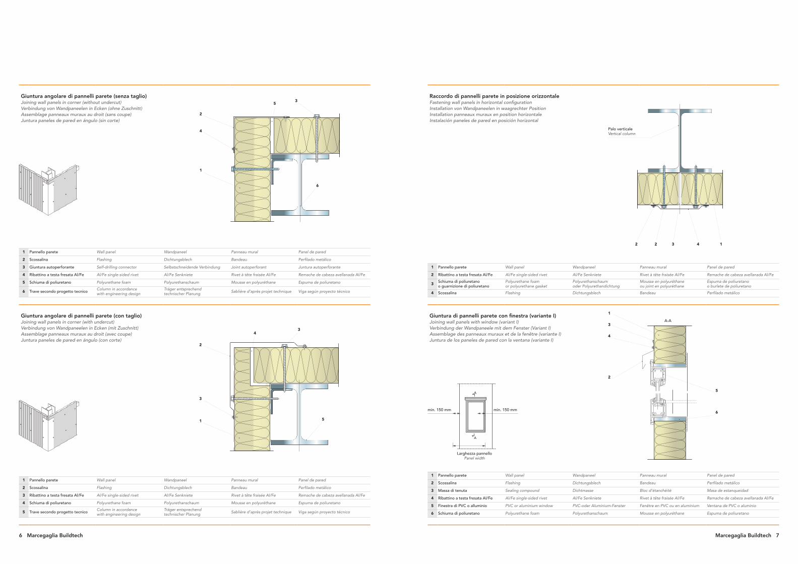
12 3 42
Palo verticaleVertical column
Larghezza pannello Panel width
min. 150 mm min. 150 mm
1
4
3
5
2
6
A-A
A
A
1
4
35
2
6
1
3
34
2
5
Raccordo di pannelli parete in posizione orizzontale Fastening wall panels in horizontal configurationInstallation von Wandpaneelen in waagrechter Position Installation panneaux muraux en position horizontaleInstalación paneles de pared en posición horizontal
1 Pannello parete Wall panel Wandpaneel Panneau mural Panel de pared
2 Ribattino a testa fresata Al/Fe Al/Fe single-sided rivet Al/Fe Senkniete Rivet à tête fraisée Al/Fe Remache de cabeza avellanada Al/Fe
3 Schiuma di poliuretano o guarnizione di poliuretano
Polyurethane foam or polyurethane gasket
Polyurethanschaum oder Polyurethandichtung
Mousse en polyuréthane ou joint en polyuréthane
Espuma de poliuretano o burlete de poliuretano
4 Scossalina Flashing Dichtungsblech Bandeau Perfilado metálico
Giuntura di pannelli parete con finestra (variante I)Joining wall panels with window (variant I) Verbindung der Wandpaneele mit dem Fenster (Variant I) Assemblage des panneaux muraux et de la fenêtre (variante I)Juntura de los paneles de pared con la ventana (variante I)
1 Pannello parete Wall panel Wandpaneel Panneau mural Panel de pared
2 Scossalina Flashing Dichtungsblech Bandeau Perfilado metálico
3 Massa di tenuta Sealing compound Dichtmasse Bloc d’étanchéité Masa de estanqueidad
4 Ribattino a testa fresata Al/Fe Al/Fe single-sided rivet Al/Fe Senkniete Rivet à tête fraisée Al/Fe Remache de cabeza avellanada Al/Fe
5 Finestra di PVC o alluminio PVC or aluminium window PVC-oder Aluminium-Fenster Fenêtre en PVC ou en aluminium Ventana de PVC o aluminio
6 Schiuma di poliuretano Polyurethane foam Polyurethanschaum Mousse en polyuréthane Espuma de poliuretano
Giuntura angolare di pannelli parete (senza taglio) Joining wall panels in corner (without undercut)Verbindung von Wandpaneelen in Ecken (ohne Zuschnitt)Assemblage panneaux muraux au droit (sans coupe)Juntura paneles de pared en ángulo (sin corte)
1 Pannello parete Wall panel Wandpaneel Panneau mural Panel de pared
2 Scossalina Flashing Dichtungsblech Bandeau Perfilado metálico
3 Giuntura autoperforante Self-drilling connector Selbstschneidende Verbindung Joint autoperforant Juntura autoperforante
4 Ribattino a testa fresata Al/Fe Al/Fe single-sided rivet Al/Fe Senkniete Rivet à tête fraisée Al/Fe Remache de cabeza avellanada Al/Fe
5 Schiuma di poliuretano Polyurethane foam Polyurethanschaum Mousse en polyuréthane Espuma de poliuretano
6 Trave secondo progetto tecnico Column in accordance with engineering design
Träger entsprechend technischer Planung Sablière d’après projet technique Viga según proyecto técnico
Giuntura angolare di pannelli parete (con taglio)Joining wall panels in corner (with undercut)Verbindung von Wandpaneelen in Ecken (mit Zuschnitt)Assemblage panneaux muraux au droit (avec coupe)Juntura paneles de pared en ángulo (con corte)
1 Pannello parete Wall panel Wandpaneel Panneau mural Panel de pared
2 Scossalina Flashing Dichtungsblech Bandeau Perfilado metálico
3 Ribattino a testa fresata Al/Fe Al/Fe single-sided rivet Al/Fe Senkniete Rivet à tête fraisée Al/Fe Remache de cabeza avellanada Al/Fe
4 Schiuma di poliuretano Polyurethane foam Polyurethanschaum Mousse en polyuréthane Espuma de poliuretano
5 Trave secondo progetto tecnico Column in accordance with engineering design
Träger entsprechend technischer Planung Sablière d’après projet technique Viga según proyecto técnico
6 Marcegaglia Buildtech Marcegaglia Buildtech 7

min. 150 mm min. 150 mm
Larghezza pannello Panel width
14
3
5
2
6
A-A
3
2
A
A
1
2
2
6
3
2
4
7
5
4
8
9
Giuntura di pannelli parete con finestra (variante II)Joining wall panels with window (variant II)Verbindung der Wandpaneele mit dem Fenster (Variant II) Assemblage des panneaux muraux et de la fenêtre (variante II) Juntura de los paneles de pared con la ventana (variante II)
1 Pannello parete Wall panel Wandpaneel Panneau mural Panel de pared
2 Scossalina Flashing Dichtungsblech Bandeau Perfilado metálico
3 Massa di tenuta ad es. butilica Sealing compound, e.g. butyl Dichtmasse z.B. Butyldichtmasse Bloc d’étanchéité, par ex en butyle Masa de estanqueidad por ej. butílica
4 Ribattino a testa fresata Al/Fe Al/Fe single-sided rivet Al/Fe Senkniete Rivet à tête fraisée Al/Fe Remache de cabeza avellanada Al/Fe
5 Finestra di PVC o alluminio PVC or aluminium window PVC-oder Aluminium-Fenster Fenêtre en PVC ou en aluminium Ventana de PVC o aluminio
6 Schiuma di poliuretano Polyurethane foam Polyurethanschaum Mousse en polyuréthane Espuma de poliuretano
Giuntura di pannelli parete con finestra (variante III)Joining wall panels with window (variant III) Verbindung der Wandpaneele mit dem Fenster (Variant III)Assemblage des panneaux muraux et de la fenêtre (variante III) Juntura de los paneles de pared con la ventana (variante III)
1 Pannello parete Wall panel Wandpaneel Panneau mural Panel de pared
2 Scossalina Flashing Dichtungsblech Bandeau Perfilado metálico
3 Ribattino a testa fresata Al/Fe Al/Fe single-sided rivet Al/Fe Senkniete Rivet à tête fraisée Al/Fe Remache de cabeza avellanada Al/Fe
4 Giuntura autoperforante Self-drilling connector Selbstschneidende Verbindung Joint autoperforant Juntura autoperforante
5 Massa di tenuta ad es. butilica Sealing compound, e.g. butyl Dichtmasse z.B. Butyldichtmasse Bloc d’étanchéité, par ex en butyle Masa de estanqueidad por ej. butílica
6 Finestra di PVC o alluminio PVC or aluminium window PVC-oder Aluminium-Fenster Fenêtre en PVC ou en aluminium Ventana de PVC o aluminio
7 Schiuma di poliuretano Polyurethane foam Polyurethanschaum Mousse en polyuréthane Espuma de poliuretano
8 Traversa di acciaio secondo progetto tecnico
Steel transom in accordance with engineering design
Stahltraverse entsprechend technischer Planung
Stahltraverse entsprechend technischer Planung
Travesaño de acero según proyecto técnico
9Barra in acciaio saldata al chiavistello secondo progetto tecnico
Flat bar welded to transom according to engineering design
Entsprechend der technischen Planung am Riegel angeschweißtes Stahlband
Barre en acier soudée au pêne d’après projet technique
Barra de acero soldada en el cerrojo según proyecto técnico
Lattonerie - AccessoriFlashings - AccessoriesBlechteile - ZubehörFerblanterie - AccessoiresRemates - Accesorios
(*) Misure progressive dal 1° lato sinistro. Per sviluppi diversi è necessaria specifica richiesta. Dimensions measured from first left side. Non standard dimensions: upon request.
Misure a magazzino per tetti con pendenza 7% Dimensions in stock for roofing with slopes 7%
Vite autofilettante, testa in acciaioSelf-tapping screw steel headSelbstgewindenschraube mit Kopf aus Stahl Vis autofiletante, tête acierTornillo autorroscante con cabeza de acero
description pcs./pack
6.3 x 20 zincata - galvanized 200
6.3 x 25 zincata - galvanized 200
6.3 x 30 zincata - galvanized 200
6.3 x 35 zincata - galvanized 200
6.3 x 40 zincata - galvanized 200
6.3 x 50 zincata - galvanized 100
6.3 x 60 zincata - galvanized 100
6.3 x 70 zincata - galvanized 100
6.3 x 80 zincata - galvanized 100
6.3 x 90 zincata - galvanized 100
6.3 x 100 zincata - galvanized 100
6.3 x 110 zincata - galvanized 100
6.3 x 120 zincata - galvanized 100
6.3 x 130 zincata - galvanized 100
6.3 x 150 zincata - galvanized 100
6.3 x 180 zincata - galvanized 100
Vite autoperforante, testa in acciaioSelf-drilling screw, steel headSelbstschneidende Schraube, StahlkopfVis autoforeuse, tête en acierTornillo autoperforante,cabeza de acero
description pcs./pack
6.3 x 20 zincata - galvanized 200
6.3 x 25 zincata - galvanized 200
6.3 x 30 zincata - galvanized 200
6.3 x 35 zincata - galvanized 200
6.3 x 40 zincata - galvanized 200
6.3 x 50 zincata - galvanized 100
6.3 x 60 zincata - galvanized 100
6.3 x 70 zincata - galvanized 100
6.3 x 80 zincata - galvanized 100
6.3 x 90 zincata - galvanized 100
6.3 x 100 zincata - galvanized 100
6.3 x 110 zincata - galvanized 100
6.3 x 120 zincata - galvanized 100
6.3 x 130 zincata - galvanized 100
6.3 x 140 zincata - galvanized 100
6.3 x 150 zincata - galvanized 100
6.3 x 160 zincata - galvanized 100
6.3 x 180 zincata - galvanized 100
6.3 x 200 zincata - galvanized 100
Vite autofilettante per legno, testa in acciaioSelf-tapping screw for wood, steel headGewindeschneidende Schraube für Holz, StahlkopfVis autofiletante pour bois, tête en acierTornillo autorroscante para madera, cabeza de acero
description pcs./pack
6.5 x 80 zincata - galvanized 100
6.5 x 90 zincata - galvanized 100
6.5 x 100 zincata - galvanized 100
6.5 x 110 zincata - galvanized 100
6.5 x 120 zincata - galvanized 100
6.5 x 130 zincata - galvanized 100
6.5 x 140 zincata - galvanized 100
6.5 x 150 zincata - galvanized 100
6.5 x 160 zincata - galvanized 100
6.5 x 180 zincata - galvanized 100
6.5 x 200 zincata - galvanized 100
Rondella in vipla Ø 6,5 mmVipla washer Ø 6.5 mmUnterlegscheibe aus Vipla, Ø 6,5 mm Rondelle en Vipla Ø 6,5 mmArandela de silicona Ø 6,5 mm
description pcs./pack
- 500
Rondella butz + inoxWasher - butz + inoxUnterlegscheibe aus Butz + EdelstahlRondelle butz + inoxArandela butz + acero inoxidable
description pcs./pack
- 100
8 Marcegaglia Buildtech Marcegaglia Buildtech 9
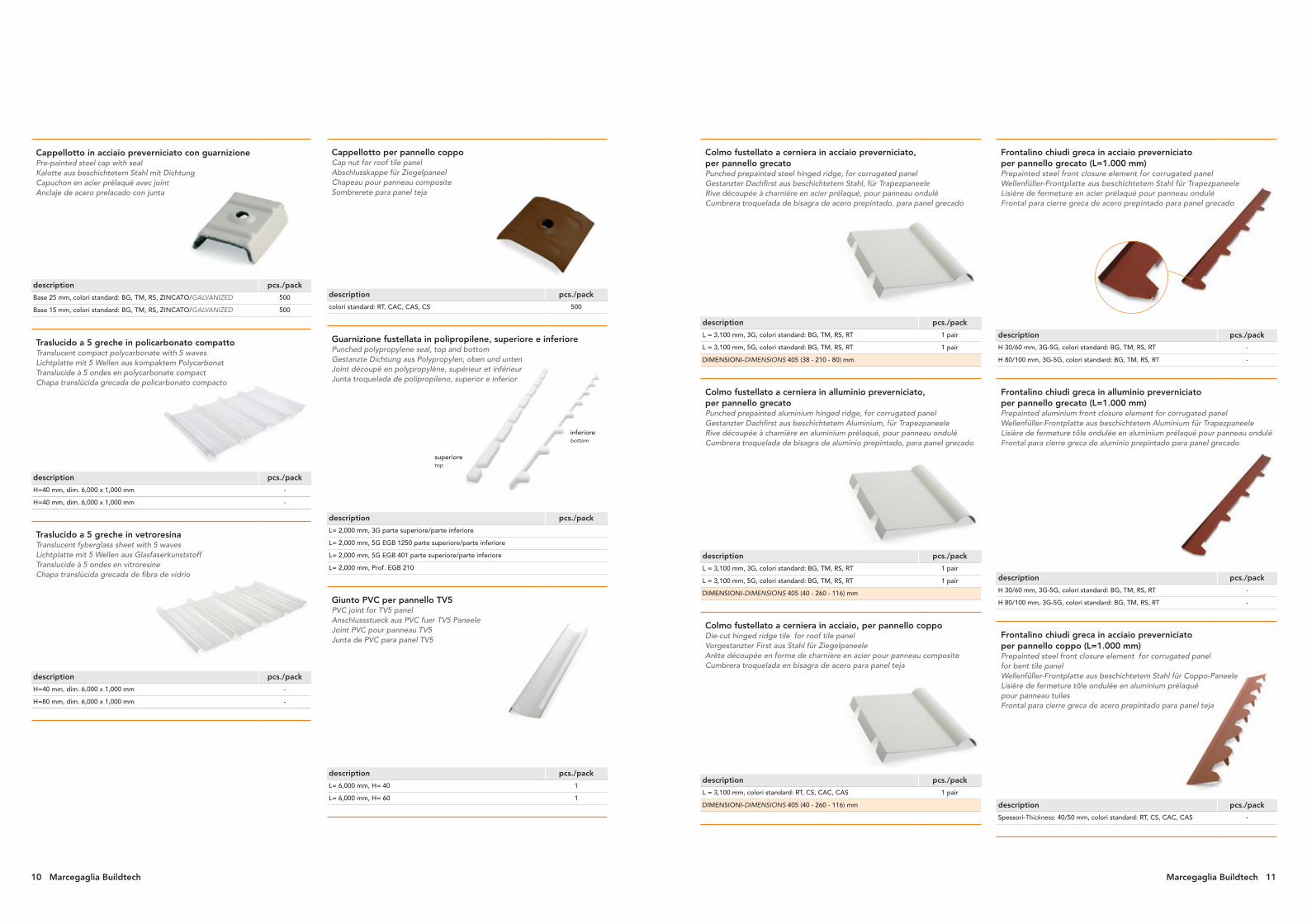
Colmo fustellato a cerniera in acciaio preverniciato, per pannello grecatoPunched prepainted steel hinged ridge, for corrugated panelGestanzter Dachfirst aus beschichtetem Stahl, für TrapezpaneeleRive découpée à charnière en acier prélaqué, pour panneau onduléCumbrera troquelada de bisagra de acero prepintado, para panel grecado
description pcs./pack
L = 3,100 mm, 3G, colori standard: BG, TM, RS, RT 1 pair
L = 3,100 mm, 5G, colori standard: BG, TM, RS, RT 1 pair
DIMENSIONI-DIMENSIONS 405 (38 - 210 - 80) mm
Colmo fustellato a cerniera in alluminio preverniciato,per pannello grecatoPunched prepainted aluminium hinged ridge, for corrugated panelGestanzter Dachfirst aus beschichtetem Aluminium, für TrapezpaneeleRive découpée à charnière en aluminium prélaqué, pour panneau onduléCumbrera troquelada de bisagra de aluminio prepintado, para panel grecado
description pcs./pack
L = 3,100 mm, 3G, colori standard: BG, TM, RS, RT 1 pair
L = 3,100 mm, 5G, colori standard: BG, TM, RS, RT 1 pair
DIMENSIONI-DIMENSIONS 405 (40 - 260 - 116) mm
Colmo fustellato a cerniera in acciaio, per pannello coppoDie-cut hinged ridge tile for roof tile panelVorgestanzter First aus Stahl für ZiegelpaneeleArête découpée en forme de charnière en acier pour panneau compositeCumbrera troquelada en bisagra de acero para panel teja
description pcs./pack
L = 3,100 mm, colori standard: RT, CS, CAC, CAS 1 pair
DIMENSIONI-DIMENSIONS 405 (40 - 260 - 116) mm
Frontalino chiudi greca in acciaio preverniciato per pannello grecato (L=1.000 mm)Prepainted steel front closure element for corrugated panel Wellenfüller-Frontplatte aus beschichtetem Stahl für TrapezpaneeleLisière de fermeture en acier prélaqué pour panneau onduléFrontal para cierre greca de acero prepintado para panel grecado
description pcs./pack
H 30/60 mm, 3G-5G, colori standard: BG, TM, RS, RT -
H 80/100 mm, 3G-5G, colori standard: BG, TM, RS, RT -
Frontalino chiudi greca in alluminio preverniciatoper pannello grecato (L=1.000 mm)Prepainted aluminium front closure element for corrugated panelWellenfüller-Frontplatte aus beschichtetem Aluminium für TrapezpaneeleLisière de fermeture tôle ondulée en aluminium prélaqué pour panneau onduléFrontal para cierre greca de aluminio prepintado para panel grecado
description pcs./pack
H 30/60 mm, 3G-5G, colori standard: BG, TM, RS, RT -
H 80/100 mm, 3G-5G, colori standard: BG, TM, RS, RT -
Frontalino chiudi greca in acciaio preverniciato per pannello coppo (L=1.000 mm)Prepainted steel front closure element for corrugated panel for bent tile panelWellenfüller-Frontplatte aus beschichtetem Stahl für Coppo-PaneeleLisière de fermeture tôle ondulée en aluminium prélaqué pour panneau tuilesFrontal para cierre greca de acero prepintado para panel teja
description pcs./pack
Spessori-Thickness: 40/50 mm, colori standard: RT, CS, CAC, CAS -
Cappellotto per pannello coppoCap nut for roof tile panel Abschlusskappe für ZiegelpaneelChapeau pour panneau compositeSombrerete para panel teja
description pcs./pack
colori standard: RT, CAC, CAS, CS 500
Guarnizione fustellata in polipropilene, superiore e inferiorePunched polypropylene seal, top and bottomGestanzte Dichtung aus Polypropylen, oben und untenJoint découpé en polypropylène, supérieur et inférieurJunta troquelada de polipropileno, superior e inferior
description pcs./pack
L= 2,000 mm, 3G parte superiore/parte inferiore
L= 2,000 mm, 5G EGB 1250 parte superiore/parte inferiore
L= 2,000 mm, 5G EGB 401 parte superiore/parte inferiore
L= 2,000 mm, Prof. EGB 210
Giunto PVC per pannello TV5PVC joint for TV5 panelAnschlussstueck aus PVC fuer TV5 PaneeleJoint PVC pour panneau TV5Junta de PVC para panel TV5
description pcs./pack
L= 6,000 mm, H= 40 1
L= 6,000 mm, H= 60 1
Cappellotto in acciaio preverniciato con guarnizionePre-painted steel cap with sealKalotte aus beschichtetem Stahl mit DichtungCapuchon en acier prélaqué avec jointAnclaje de acero prelacado con junta
description pcs./pack
Base 25 mm, colori standard: BG, TM, RS, ZINCATO/GALVANIZED 500
Base 15 mm, colori standard: BG, TM, RS, ZINCATO/GALVANIZED 500
Traslucido a 5 greche in policarbonato compattoTranslucent compact polycarbonate with 5 wavesLichtplatte mit 5 Wellen aus kompaktem PolycarbonatTranslucide à 5 ondes en polycarbonate compactChapa translúcida grecada de policarbonato compacto
description pcs./pack
H=40 mm, dim. 6,000 x 1,000 mm -
H=40 mm, dim. 6,000 x 1,000 mm -
Traslucido a 5 greche in vetroresinaTranslucent fyberglass sheet with 5 wavesLichtplatte mit 5 Wellen aus GlasfaserkunststoffTranslucide à 5 ondes en vitroresineChapa translúcida grecada de fibra de vidrio
description pcs./pack
H=40 mm, dim. 6,000 x 1,000 mm -
H=80 mm, dim. 6,000 x 1,000 mm -
superioretop
inferiorebottom
10 Marcegaglia Buildtech Marcegaglia Buildtech 11

FermaneveSnow stopperSchneefangProtection neigeTope paranieve
description pcs./pack
3,100 mm, colori standard: BG, TM, RS -
DIMENSIONI-DIMENSIONS 505 (20-50-215-150-50-20) mm (*)
Raccordo di faldaPitch connection fittingDachstulpanschlussRaccord de bande de riveUnión de cubierta
description pcs./pack
3,100 mm, 90-100-280-40, colori standard: BG, TM, RS -
DIMENSIONI-DIMENSIONS 395/525 (15-90-100-150/280-40) mm (*)
Colmo pressopiegato fustellato (capannina)Pressed and punched ridgeGestanzter und gebogener DachfirstFaîtière plié sous pression à boudin crantéCumbrera plegada troquelada
description pcs./pack
3,100 mm, 40-270-270-40, colori standard: BG, TM, RS -
DIMENSIONI-DIMENSIONS 410 (40-165-165-40) mm (*)
COLORI STANDARD - Tipo verniciatura standard poliestere MP3Standard colours - Standard painting MP3 polyester
material code Marcegaglia code RAL colour description
acciaiosteel M 1301 9002* bianco grigiastro (BG)
grey white
acciaiosteel M 4301 3009* rosso siena (RS)
oxide red
acciaiosteel M 5301 8017* testa di moro (TM)
chocolate brown
alluminioaluminium M 1305 9002* bianco grigiastro (BG)
grey white
alluminioaluminium M 4307 3009* rosso siena (RS)
oxide red
alluminioaluminium M 5331 8017* testa di moro (TM)
chocolate brown
* simile al * similar to
GocciolatoioDripWasserablaufnaseGauttièreBabero
description pcs./pack
3,100 mm, 60-60-60-20, colori standard: BG, TM, RS -
DIMENSIONI-DIMENSIONS 200 (50-70-20-40-20) mm (*)
SottocolmoUnder ridgeUnterdachfirstSous faîtièreBajo cumbrera
description pcs./pack
3,100 mm, 15-235-235-15, colori standard: BG, TM, RS -
DIMENSIONI-DIMENSIONS 410 (10-195-195-10) mm (*)
Raccordo a muroWall fittingWandanschlussRaccordement contre murRemate a muro
description pcs./pack
3,100 mm, 20-90-266-40, colori standard: BG, TM, RS -
DIMENSIONI-DIMENSIONS 310 (20-50-200-40) mm (*)
Raccordo di testataHead fittingGiebelanschlussRaccord de têteRemate de coronación
description pcs./pack
3,100 mm, 75-250-80-25-50-25, colori standard: BG, TM, RS -
DIMENSIONI-DIMENSIONS 500 (75-250-80-25-50-25) mm (*)
Angolare esternoExternal angle sectionAussenwinkelstueckÉlément d’angle externeEsquina exterior
description pcs./pack
3,100 mm, colori standard: BG, TM, RS -
DIMENSIONI-DIMENSIONS 330 (16-150-150-16) mm (*)
Angolare internoInternal angle sectionInnenwinkelstueckÉlément d’angle interneEsquina interior
description pcs./pack
3,100 mm, colori standard: BG, TM, RS -
DIMENSIONI-DIMENSIONS 330 (16-150-150-16) mm (*)
Supporto di faldaPitch supportDachstulptraegerSupport de bande de riveSoporte de cubierta
description pcs./pack
3,100 mm, 213-80-40, colori standard: BG, TM, RS -
DIMENSIONI-DIMENSIONS 330 (40-80-210) mm (*)
Lamiera piana in acciaio preverniciatoFlat sheet prepainted steelFlachblech aus beschichtetem StahlTôle plane en acier prelaquéChapa plana de acero prelacado
description pcs./pack
dim. 1,250 x 3,000 mm, Spessori-Thickness 0,6-0,8 mmcolori standard: BG, TM, RS, RT
25
Raccordo 5 greche EGB 1250 tacchettataNotched connection fitting 5 waves EGB 1250Anschlussstueck mit 5 Wellen fuer EGB 1250 SchaltstufentrapezblechRaccord 5 ondes EGB 1250 crantéElemento de unión grecado EGB 1250 nervado
description pcs./pack
Larghezza-Strip width 1,000 x Max 6,000
Gronda esternaExternal gutterAussenwasserspeierGouttière externeCornisa exterior
description pcs./pack
3,100 mm, 15-35-140-150-80-15, colori standard: BG, TM, RS -
DIMENSIONI-DIMENSIONS 610 (15-30-200-150-100-110-15) (*)
ConversaDrawDachkehleChéneauCanalón
description pcs./pack
3,100 mm, colori standard: BG, TM, RS -
DIMENSIONI-DIMENSIONS 620 (60-150-200-150-60) (*)
lato verniciatopainted side
lato verniciatopainted side
12 Marcegaglia Buildtech Marcegaglia Buildtech 13
14 Marcegaglia Buildtech
Sales office: via Giovanni della Casa, 12 • 20151 Milano - Italy
phone +39 . 02 30 704.1 • fax +39 . 02 33 402 706
[email protected] • www.marcegagliabuildtech.it
Plants and sales offices: MARCEGAGLIA Pozzolo Formigarostrada Roveri, 4 • 15068 Pozzolo Formigaro, Alessandria - Italy
phone +39 . 0143 77 61 • fax +39 . 0143 77 63 53
MARCEGAGLIA POLAND Praszkaul. Kaliska, 72 - 46-320 Praszka - Poland
phone +48 . 34 . 350 15 93 • fax +48 . 34 . 350 15 01
[email protected] • www.marcegaglia.pl
Janu
ary
2018