SP-20 SP-25 SP-32 SP-40 · Consumo d’aria per ciclo ... G Ø4H8 x 6 mm Ø4H8 x 6.5 mm Ø5H8 x 9...
14
www.gimatic.com 190 09/2018 SP SP-20 SP-25 SP-32 SP-40 SP Pinze parallele a 2 griffe / 2-jaw parallel grippers Pinza pneumatica a 2 griffe ad azione parallela autocentrante (serie SP) • Azionamento a doppio effetto. • Meccanismo di regolazione del gioco esclusivo. • Grande durata e affidabilità senza manutenzione. • Diverse possibilità di fissaggio e alimentazione. • Sensori magnetici opzionali. • Grasso alimentare FDA-H1. SP-20 SP-25 SP-32 SP-40 Fluido Medium Aria compressa filtrata, lubrificata / non lubrificata Filtered, lubricated / non lubricated compressed air Pressione di esercizio Operating pressure range 2.5 ÷ 8 bar Temperatura di esercizio Operating temperature range 5° ÷ 60°C. Forza di serraggio per griffa in apertura a 6 bar Opening gripping force at 6 bar on each jaw 70 N 120 N 220 N 350 N Forza di serraggio totale in apertura a 6 bar Total opening gripping force at 6 bar 140 N 240 N 440 N 700 N Forza di serraggio per griffa in chiusura a 6 bar Closing gripping force at 6 bar on each jaw 65 N 110 N 200 N 320 N Forza di serraggio totale in chiusura a 6 bar Total closing gripping force at 6 bar 130 N 220 N 400 N 640 N Corsa totale (±0.2 mm) Total stroke 8 mm 12 mm 16 mm 20 mm Frequenza max funzionamento continuativo Maximum continuous operating frequency 3 Hz 2 Hz 2 Hz 2 Hz Consumo d’aria per ciclo Air consumption per cycle 3 cm 3 6 cm 3 13 cm 3 31 cm 3 Tempo di chiusura senza carico Closing time without load 0.03 s 0.05 s 0.05 s 0.05 s Tolleranza max ripetibilità Maximum repeatability tolerance ±0.02 mm ±0.02 mm ±0.02 mm ±0.02 mm Peso Weight 105 g 210 g 380 g 600 g 2-jaw self-centering parallel pneumatic gripper (series SP) • Double-acting drive. • Exclusive backlash adjusting system. • Maintenance-free long life and reliability. • Various mounting and feeding options. • Optional magnetic sensors. • FDA-H1 food-grade grease.
Transcript of SP-20 SP-25 SP-32 SP-40 · Consumo d’aria per ciclo ... G Ø4H8 x 6 mm Ø4H8 x 6.5 mm Ø5H8 x 9...

www.gimatic.com190
09
/20
18
SP
SP-20 SP-25 SP-32 SP-40
SP
Pinze parallele a 2 griffe / 2-jaw parallel grippers
Pinza pneumatica a 2 griffe ad azione parallela autocentrante (serie SP)• Azionamento a doppio effetto.• Meccanismo di regolazione del gioco esclusivo.• Grande durata e affidabilità senza manutenzione.• Diverse possibilità di fissaggio e alimentazione.• Sensori magnetici opzionali.• Grasso alimentare FDA-H1.
SP-20 SP-25 SP-32 SP-40
FluidoMedium
Aria compressa filtrata, lubrificata / non lubrificataFiltered, lubricated / non lubricated compressed air
Pressione di esercizioOperating pressure range
2.5 ÷ 8 bar
Temperatura di esercizioOperating temperature range
5° ÷ 60°C.
Forza di serraggio per griffa in apertura a 6 barOpening gripping force at 6 bar on each jaw
70 N 120 N 220 N 350 N
Forza di serraggio totale in apertura a 6 barTotal opening gripping force at 6 bar
140 N 240 N 440 N 700 N
Forza di serraggio per griffa in chiusura a 6 barClosing gripping force at 6 bar on each jaw
65 N 110 N 200 N 320 N
Forza di serraggio totale in chiusura a 6 barTotal closing gripping force at 6 bar
130 N 220 N 400 N 640 N
Corsa totale (±0.2 mm)Total stroke
8 mm 12 mm 16 mm 20 mm
Frequenza max funzionamento continuativoMaximum continuous operating frequency
3 Hz 2 Hz 2 Hz 2 Hz
Consumo d’aria per cicloAir consumption per cycle
3 cm3 6 cm3 13 cm3 31 cm3
Tempo di chiusura senza caricoClosing time without load
0.03 s 0.05 s 0.05 s 0.05 s
Tolleranza max ripetibilitàMaximum repeatability tolerance
±0.02 mm ±0.02 mm ±0.02 mm ±0.02 mm
PesoWeight
105 g 210 g 380 g 600 g
2-jaw self-centering parallel pneumatic gripper (series SP)• Double-acting drive.• Exclusive backlash adjusting system.• Maintenance-free long life and reliability.• Various mounting and feeding options.• Optional magnetic sensors.• FDA-H1 food-grade grease.
www.gimatic.com 191
09
/20
18
SP
9
C L24
±0.0
2
Ø3
H8
5
Ø3 H8 5
31
30
C L23
C L28
32
C L22
C L35
C L42
9
18
C L13
6
14
(N°2) M5
A
B
M4
610
Ø3
.3
5Ø 3.3
Ø6
CL 28
CL 22
C L10
C L24
7.6
C L35
±0
.02
C L54
D
C
C L58
C L35
C L50
CL 8
CL 22
6
9
12
2
8
C L5
+0.0
5+0.0
2
C L18
7
M3
Ø4
H8
M3
Ø5.3
Ø7
0.72
D C
O-Ring Ø1x5mm(GUAR-021)
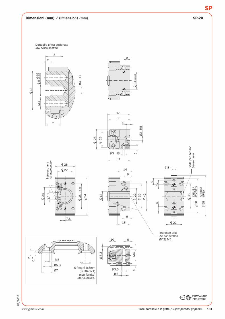
SP-20
Pinze parallele a 2 griffe / 2-jaw parallel grippers
Dettaglio griffa sezionata
(non fornito)
Sed
e pe
r se
nsor
i
APER
TA
CH
IUS
A
Ingresso aria
Ingr
esso
aria
Dimensioni (mm) / Dimensions (mm)
Jaw cross section
Sen
sor
seat
Air connection
Air
conn
ectio
n
OPE
N
CLO
SED
(not supplied)
www.gimatic.com192
09
/20
18
SP
18
C L20
±0.0
2
10
Ø4
H8
Ø4 H8
38
41
C L28.5
C L36
4
3
C L16
17
13.5 7
C L42
C L52B A
M51226
Ø7
.3
13
Ø 4.1
Ø7.3
C L76
10.5
C L13
CL 27
CL 36
C L64
CL 12
41.5 max.
10
CL 27
CL 36
60°
14 C L28
C L42
±0
.02
C L68
D
C
2.5
10
5+0.0
5+0.0
2
Ø4
36
8
22
max
.
M4
0.7 M 3
Ø5.3
Ø7.3
2
O-Ring Ø1x5.5mm(GUAR-087)
D C
(N°2
) M
5
(N°2
) M
3
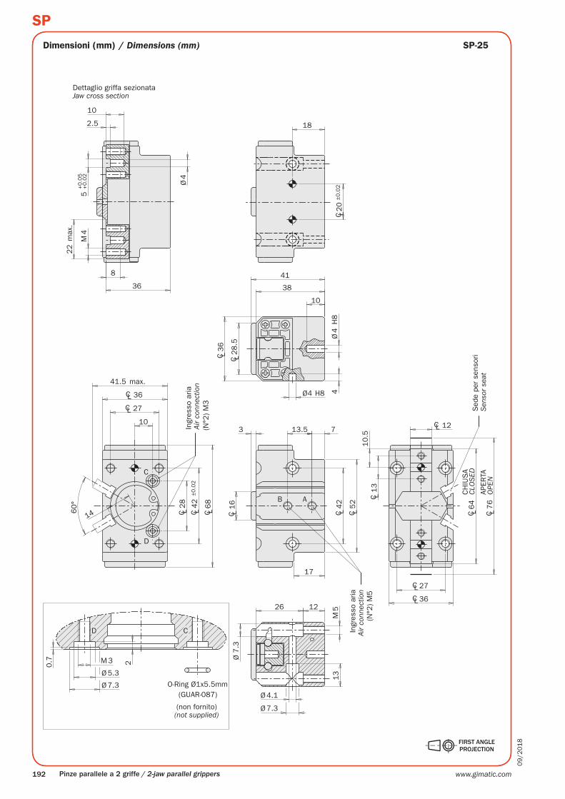
SP-25
Pinze parallele a 2 griffe / 2-jaw parallel grippers
Dimensioni (mm) / Dimensions (mm)
Dettaglio griffa sezionata
Sed
e pe
r se
nsor
iAP
ERTA
CH
IUS
A
Ingr
esso
aria
Ingr
esso
aria
(non fornito)
Jaw cross section
Sen
sor
seat
Air
conn
ectio
n
OPE
N
CLO
SED
Air
conn
ectio
n
(not supplied)
www.gimatic.com 193
09
/20
18
SP
20
C L40
±0.0
2
C L25
22
26
C L52
9
20
C L64
C L36
B
A
Ø7
.6
Ø5.3
Ø8.8
M5
34 14
16
C L96
C L80
C L52
C L16
13
CL14CL 32
CL 42
C L36
C L52
±0
.02
C L84
17.6
52°
9
(N°2
) M
3
(N°2
) M
5
D
C
M3x4mm DIN913
Ø4 H8 7
51
Ø4
H8
6
C L42
C L37
C L14
46
48
3 10
3
12
C L6
+0.0
5+0.0
2
Ø5
H8
O-Ring Ø1x4mm (GUAR-091)
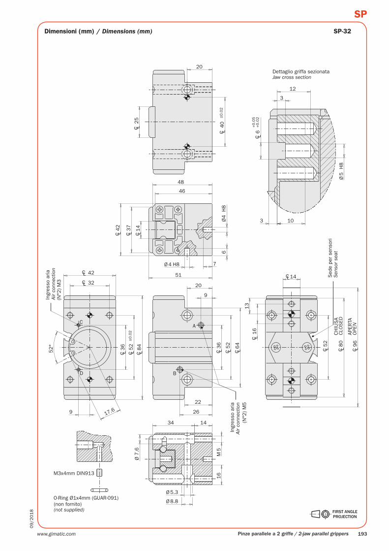
SP-32
Pinze parallele a 2 griffe / 2-jaw parallel grippers
Dimensioni (mm) / Dimensions (mm)
Dettaglio griffa sezionata
Sed
e pe
r se
nsor
i
APER
TA
CH
IUS
A
Ingr
esso
aria
Ingr
esso
aria
(non fornito)
Jaw cross section
Sen
sor
seat
Air
conn
ectio
n
OPE
N
CLO
SED
Air
conn
ectio
n
(not supplied)
www.gimatic.com194
09
/20
18
SP
25
C L50
±0.0
2
C L25
6
51
54
Ø5
H8
Ø5 H8 6
56
C L14
.2
C L50
C L47
C L66
C L80
28
31.5
10
25
B
A
(N°2
) M
5
M6
19
9.5
35
Ø9
Ø6.5
Ø11
19
C L120
C L20
16
CL 14.2
C L66
C L100
CL 38
CL 38
CL 50
64°
C L44
C L66
±0
.02
C L105
13
(N°2
) M
5
D
C
3
13
15
Ø6
H8
C L8
+0.0
2+0.0
5M
6
123
32
M5x5mm DIN913
O-Ring Ø1x6mm (GUAR-098)
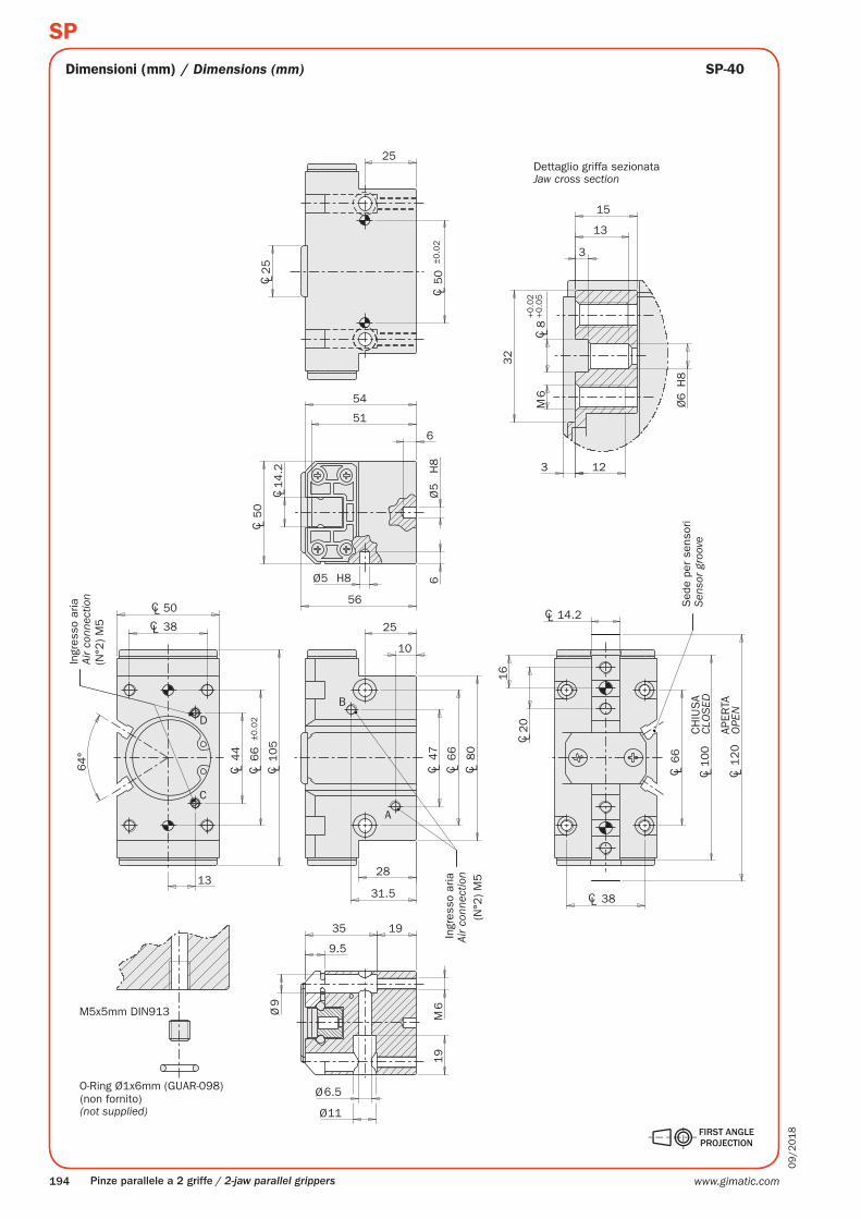
SP-40
Pinze parallele a 2 griffe / 2-jaw parallel grippers
Dimensioni (mm) / Dimensions (mm)
Dettaglio griffa sezionata
Sed
e pe
r se
nsor
i
APER
TA
CH
IUS
A
Ingr
esso
aria
Ingr
esso
aria
(non fornito)
Jaw cross section
Sen
sor
groo
ve
Air
conn
ectio
n
OPE
N
CLO
SED
Air
conn
ectio
n
(not supplied)

www.gimatic.com 195
09
/20
18
SP
ZA
SP-25
Pinze parallele a 2 griffe / 2-jaw parallel grippers
SerraggioLa pinza è a doppio effetto e può quindi essere usata per serrare il carico sia dall’esterno che dall’interno.La forza di serraggio è maggiore in apertura.
Esempio di applicazione
Camera in pressione
interfaccia
GrippingThe gripper is double-acting for either internal or external gripping applications.The gripping force on opening is higher.
Application example
Pressurized chamber
interface
www.gimatic.com196
09
/20
18
SP
C
A
B
D
D
E
1
2
3
Pinze parallele a 2 griffe / 2-jaw parallel grippers
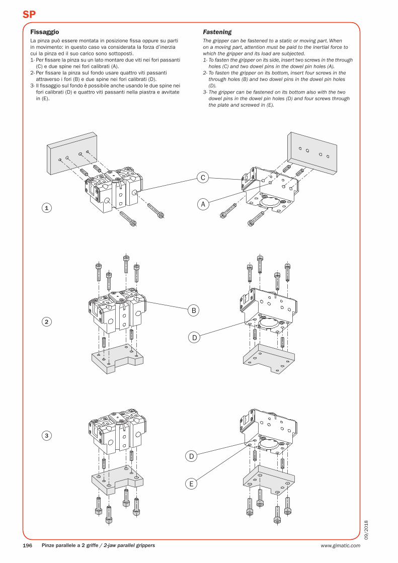
FissaggioLa pinza può essere montata in posizione fissa oppure su parti in movimento: in questo caso va considerata la forza d’inerzia cui la pinza ed il suo carico sono sottoposti.1- Per fissare la pinza su un lato montare due viti nei fori passanti
(C) e due spine nei fori calibrati (A).2- Per fissare la pinza sul fondo usare quattro viti passanti
attraverso i fori (B) e due spine nei fori calibrati (D).3- Il fissaggio sul fondo è possibile anche usando le due spine nei
fori calibrati (D) e quattro viti passanti nella piastra e avvitate in (E).
FasteningThe gripper can be fastened to a static or moving part. When on a moving part, attention must be paid to the inertial force to which the gripper and its load are subjected.1- To fasten the gripper on its side, insert two screws in the through
holes (C) and two dowel pins in the dowel pin holes (A).2- To fasten the gripper on its bottom, insert four screws in the
through holes (B) and two dowel pins in the dowel pin holes (D).
3- The gripper can be fastened on its bottom also with the two dowel pins in the dowel pin holes (D) and four screws through the plate and screwed in (E).
www.gimatic.com 197
09
/20
18
SP
F
G
H
45°
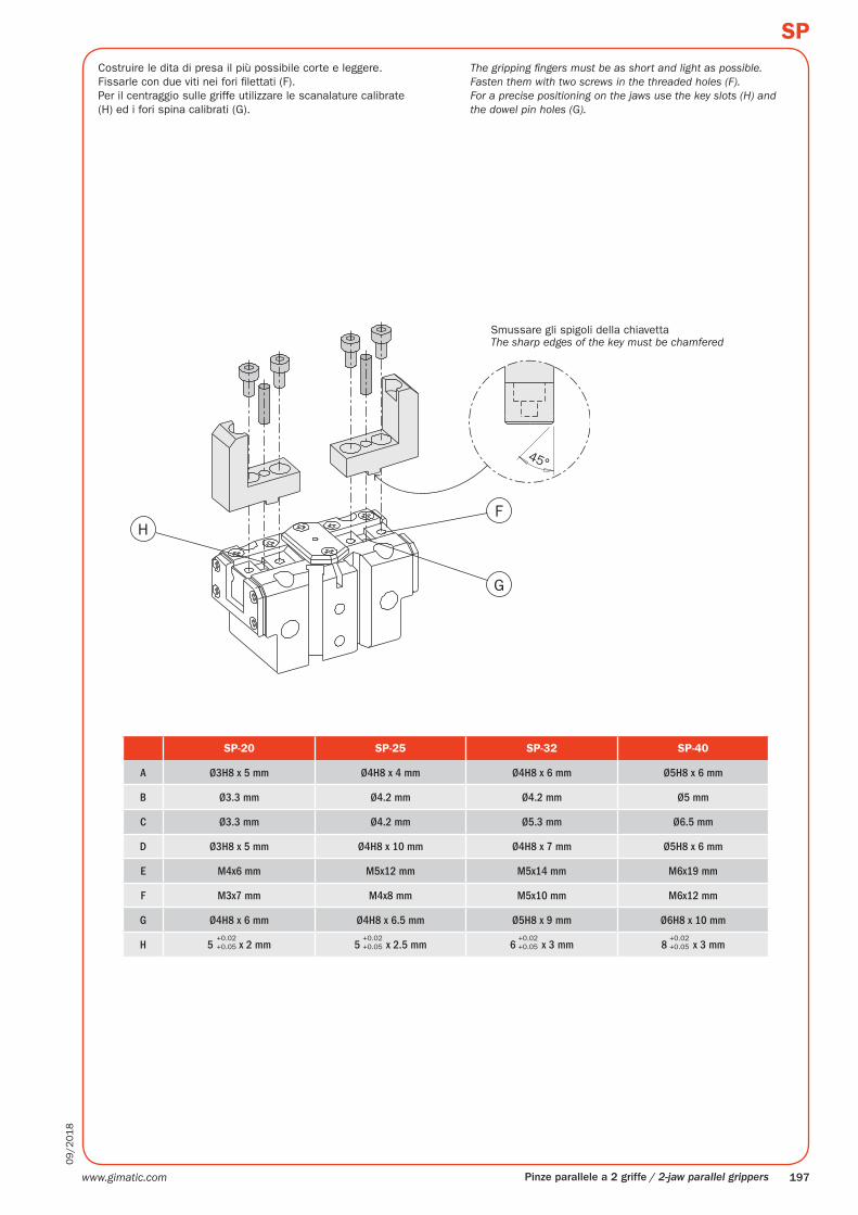
SP-20 SP-25 SP-32 SP-40
A Ø3H8 x 5 mm Ø4H8 x 4 mm Ø4H8 x 6 mm Ø5H8 x 6 mm
B Ø3.3 mm Ø4.2 mm Ø4.2 mm Ø5 mm
C Ø3.3 mm Ø4.2 mm Ø5.3 mm Ø6.5 mm
D Ø3H8 x 5 mm Ø4H8 x 10 mm Ø4H8 x 7 mm Ø5H8 x 6 mm
E M4x6 mm M5x12 mm M5x14 mm M6x19 mm
F M3x7 mm M4x8 mm M5x10 mm M6x12 mm
G Ø4H8 x 6 mm Ø4H8 x 6.5 mm Ø5H8 x 9 mm Ø6H8 x 10 mm
H 5 x 2 mm 5 x 2.5 mm 6 x 3 mm 8 x 3 mm+0.02+0.05
+0.02+0.05
+0.02+0.05
+0.02+0.05
Pinze parallele a 2 griffe / 2-jaw parallel grippers
Costruire le dita di presa il più possibile corte e leggere.Fissarle con due viti nei fori filettati (F).Per il centraggio sulle griffe utilizzare le scanalature calibrate (H) ed i fori spina calibrati (G).
Smussare gli spigoli della chiavetta
The gripping fingers must be as short and light as possible.Fasten them with two screws in the threaded holes (F).For a precise positioning on the jaws use the key slots (H) and the dowel pin holes (G).
The sharp edges of the key must be chamfered
www.gimatic.com198
09
/20
18
SP
10 504030200
8 bar
4 bar
6 bar
10
0
40
20
30
50
60
70
80
90
100
10 504030200
8 bar
4 bar
6 bar
15 756045300
8 bar
4 bar
6 bar
20
0
80
40
60
100
120
140
160
180
200
15 756045300
8 bar
4 bar
6 bar
20 1008060400
8 bar
4 bar
6 bar
30
0
120
60
90
150
180
210
240
270
300
0
8 bar
4 bar
6 bar
10 504030200
10
40
20
30
50
25 12510075500
8 bar
4 bar
6 bar
50
0
200
100
150
250
300
350
400
450
500
0
8 bar
4 bar
6 bar
10
0
40
20
30
50
60
70
80
90
100
20
0
80
40
60
100
120
140
160
180
200
30
0
120
60
90
150
180
210
240
270
300
50
0
200
100
150
250
300
350
400
450
500
20 100806040
25 1251007550
10 504030200
10
40
20
30
50
15 756045300
15
60
30
45
75
20 1008060400
20
80
40
60
100
25 12510075500
25
100
50
75
125
15 756045300
15
60
30
45
75
20 1008060400
20
80
40
60
100
25 12510075500
25
100
50
75
125
350 N
220 N
175 N
148 N
128 N
117 N
109 N
200 N
159 N
135 N
116 N
106 N
99 N
110 N
93 N
80 N
68 N
60 N
54 N
120 N
101 N
87 N
75 N
66 N
59 N
70 N
64 N
58 N
53 N
49 N
45 N
65 N
59 N
54 N
49 N
46 N
42 N
310 N
279 N
247 N
219 N
199 N
320 N
284 N
255 N
225 N
200 N
182 N
Z
X
SP-20
SP-25
SP-32
SP-40
Pinze parallele a 2 griffe / 2-jaw parallel grippers
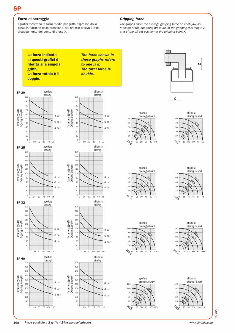
Forza di serraggioI grafici mostrano la forza media per griffa espressa dalla pinza in funzione della pressione, del braccio di leva Z e del disassamento del punto di presa X.
apertura
apertura
apertura
apertura
apertura
apertura
apertura
apertura
La forza indicata in questi grafici è riferita alla singola griffa. La forza totale è il doppio.
Forza
serra
ggio
(N)
Forza
serra
ggio
(N)
Forza
serra
ggio
(N)
Forza
serra
ggio
(N)
Forza
serra
ggio
(N)
Forza
serra
ggio
(N)
Forza
serra
ggio
(N)
Forza
serra
ggio
(N)
chiusura
chiusura
chiusura
chiusura
chiusura
chiusura
chiusura
chiusura
Gripping forceThe graphs show the average gripping force on each jaw, as function of the operating pressure, of the gripping tool length Z and of the off-set position of the gripping point X.
Gripp
ing fo
rce
(N)
Gripp
ing fo
rce
(N)
closing
The force shown in these graphs refers to one jaw. The total force is double.
opening
opening (6 bar)
closingopening
Gripp
ing fo
rce
(N)
Gripp
ing fo
rce
(N)
closingopening
Gripp
ing fo
rce
(N)
Gripp
ing fo
rce
(N)
closingopening
Gripp
ing fo
rce
(N)
Gripp
ing fo
rce
(N)
closing (6 bar)
opening (6 bar) closing (6 bar)
opening (6 bar)
opening (6 bar)
closing (6 bar)
closing (6 bar)
www.gimatic.com 199
09
/20
18
SP
SP-20 SP-25 SP-32 SP-40
Fx s 100 N 200 N 300 N 400 N
Fy s 100 N 200 N 300 N 400 N
Mx s 3 Nm 6 Nm 13 Nm 30 Nm
My s 3 Nm 6 Nm 13 Nm 30 Nm
Mz s 3 Nm 6 Nm 13 Nm 30 Nm
Fx d 1 N 2 N 3 N 4 N
Fy d 1 N 2 N 3 N 4 N
Mx d 5 Ncm 12 Ncm 24 Ncm 40 Ncm
My d 5 Ncm 12 Ncm 24 Ncm 40 Ncm
Mz d 5 Ncm 12 Ncm 24 Ncm 40 Ncm
m 100 g 200 g 300 g 400 g
Pinze parallele a 2 griffe / 2-jaw parallel grippers
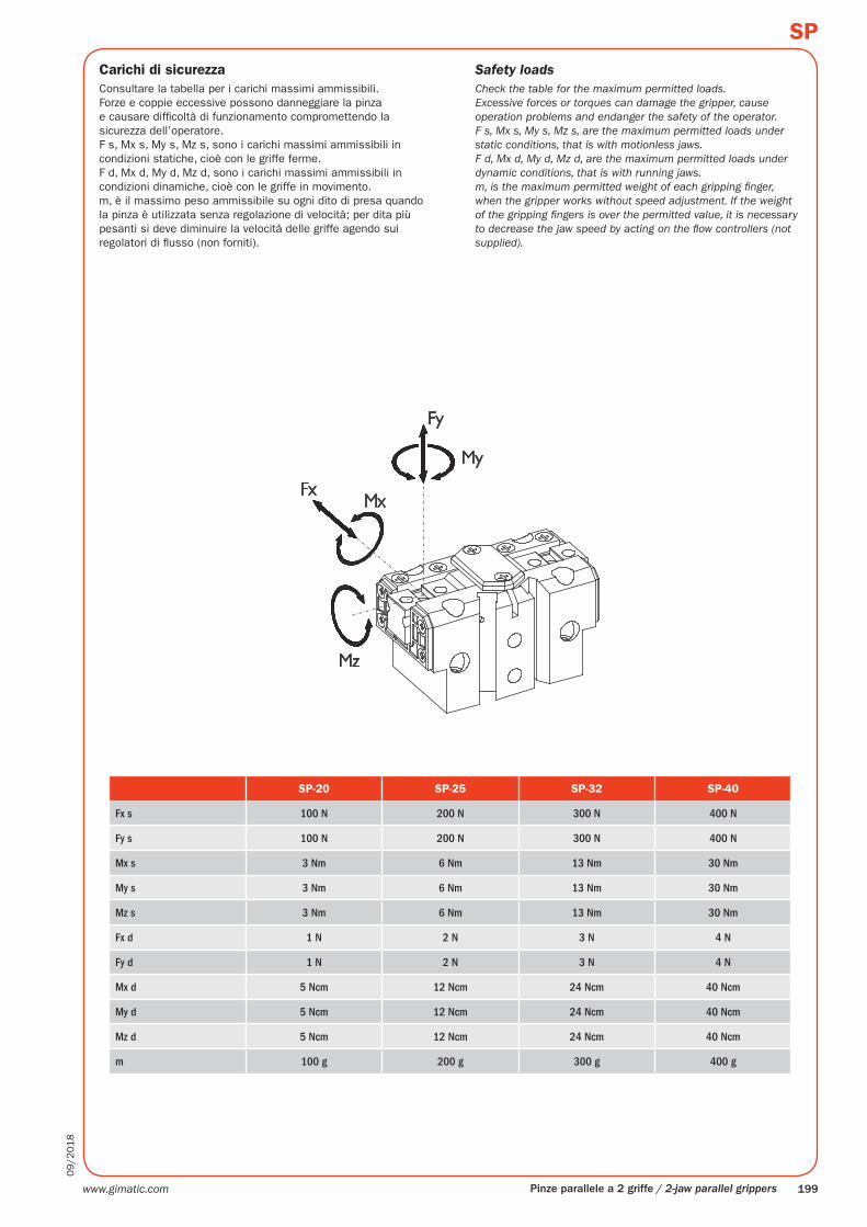
Carichi di sicurezzaConsultare la tabella per i carichi massimi ammissibili.Forze e coppie eccessive possono danneggiare la pinza e causare difficoltà di funzionamento compromettendo la sicurezza dell’operatore.F s, Mx s, My s, Mz s, sono i carichi massimi ammissibili in condizioni statiche, cioè con le griffe ferme.F d, Mx d, My d, Mz d, sono i carichi massimi ammissibili in condizioni dinamiche, cioè con le griffe in movimento.m, è il massimo peso ammissibile su ogni dito di presa quando la pinza è utilizzata senza regolazione di velocità; per dita più pesanti si deve diminuire la velocità delle griffe agendo sui regolatori di flusso (non forniti).
Safety loadsCheck the table for the maximum permitted loads.Excessive forces or torques can damage the gripper, cause operation problems and endanger the safety of the operator.F s, Mx s, My s, Mz s, are the maximum permitted loads under static conditions, that is with motionless jaws.F d, Mx d, My d, Mz d, are the maximum permitted loads under dynamic conditions, that is with running jaws.m, is the maximum permitted weight of each gripping finger, when the gripper works without speed adjustment. If the weight of the gripping fingers is over the permitted value, it is necessary to decrease the jaw speed by acting on the flow controllers (not supplied).
www.gimatic.com200
09
/20
18
SP
OUT
OUT
PNP
NPN
Magneto-resistive
SC... SL...
SN...SS...
SS.004.000
SS...SL...
SC...
Pinze parallele a 2 griffe / 2-jaw parallel grippers
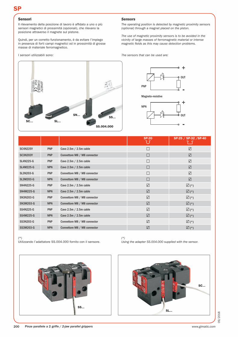
SensoriIl rilevamento della posizione di lavoro è affidato a uno o più sensori magnetici di prossimità (opzionali), che rilevano la posizione attraverso il magnete sul pistone.
Quindi, per un corretto funzionamento, è da evitare l’impiego in presenza di forti campi magnetici od in prossimità di grosse masse di materiale ferromagnetico.
I sensori utilizzabili sono:
(*)Utilizzando l’adattatore SS.004.000 fornito con il sensore.
SP-20 SP-25 / SP-32 /SP-40
SC4N225Y PNP Cavo 2.5m / 2.5m cable ✓
SC3N203Y PNP Connettore M8 / M8 connector ✓
SL4N225-G PNP Cavo 2.5m / 2.5m cable ✓
SL4M225-G NPN Cavo 2.5m / 2.5m cable ✓
SL3N203-G PNP Connettore M8 / M8 connector ✓
SL3M203-G NPN Connettore M8 / M8 connector ✓
SN4N225-G PNP Cavo 2.5m / 2.5m cable ✓ ✓ (*)
SN4M225-G NPN Cavo 2.5m / 2.5m cable ✓ ✓ (*)
SN3N203-G PNP Connettore M8 / M8 connector ✓ ✓ (*)
SN3M203-G NPN Connettore M8 / M8 connector ✓ ✓ (*)
SS4N225-G PNP Cavo 2.5m / 2.5m cable ✓ ✓ (*)
SS4M225-G NPN Cavo 2.5m / 2.5m cable ✓ ✓ (*)
SS3N203-G PNP Connettore M8 / M8 connector ✓ ✓ (*)
SS3M203-G NPN Connettore M8 / M8 connector ✓ ✓ (*)
(*)Using the adapter SS.004.000 supplied with the sensor.
SensorsThe operating position is detected by magnetic proximity sensors (optional) through a magnet placed on the piston.
The use of magnetic proximity sensors is to be avoided in the vicinity of large masses of ferromagnetic material or intense magnetic fields as this may cause detection problems.
The sensors that can be used are:
www.gimatic.com 201
09
/20
18
SP
SP-32/SP-40SP-20/SP-25
CD
AB
B
A
CD
Pinze parallele a 2 griffe / 2-jaw parallel grippers
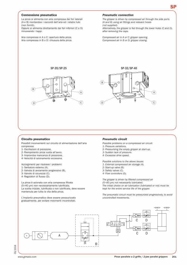
Connessione pneumaticaLa pinza si alimenta con aria compressa dai fori laterali(A e B) montandovi i raccordi dell’aria ed i relativi tubi(non forniti).Oppure si alimenta direttamente dai fori inferiori (C e D) rimuovendo i tappi.
Aria compressa in A o C: apertura della pinza.Aria compressa in B o D: chiusura della pinza.
Circuito pneumaticoPossibili inconvenienti sul circuito di alimentazione dell’aria compressa:1- Oscillazioni di pressione.2- Riempimento pinza vuota all’avvio.3- Improvvisa mancanza di pressione.4- Velocità di azionamento eccessiva.
Accorgimenti per risolvere i problemi:1- Serbatoio esterno (A).2- Valvola di avviamento progressivo (B).3- Valvole di sicurezza (C).4- Regolatori di flusso (D).
La pinza è azionata con aria compressa filtrata(5÷40 µm) non necessariamente lubrificata.La scelta iniziale, lubrificata o non lubrificata, deve essere mantenuta per tutta la vita della pinza.
L’impianto pneumatico deve essere pressurizzato gradualmente, per evitare movimenti incontrollati.
Pneumatic connectionThe gripper is driven by compressed air through the side ports(A and B) using air fittings and relevant hoses(not supplied).Alternatively, the gripper is fed through the lower holes (C and D), after removing the caps.
Compressed air in A or C: gripper opening.Compressed air in B or D: gripper closing.
Pneumatic circuitPossible problems on a compressed air circuit:1- Pressure variations.2- Pressurising the empty gripper at start-up.3- Sudden lack of pressure.4- Excessive drive speed.
Possible solutions to the above issues:1- External compressed air storage (A).2- Start-up valve (B).3- Safety valves (C).4- Flow controllers (D).
The gripper is driven by filtered compressed air(5÷40 µm) not necessarily lubricated.The initial choice on air lubrication (lubricated or not) must be kept for the entire service life of the gripper.
The pneumatic circuit must be pressurized progressively, to avoid uncontrolled movements.
www.gimatic.com202
09
/20
18
SP
Pinze parallele a 2 griffe / 2-jaw parallel grippers
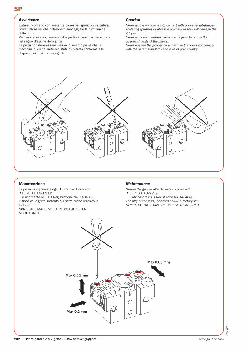
AvvertenzeEvitare il contatto con sostanze corrosive, spruzzi di saldatura, polveri abrasive, che potrebbero danneggiare la funzionalità della pinza.Per nessun motivo, persone od oggetti estranei devono entrare nel raggio d’azione della pinza.La pinza non deve essere messa in servizio prima che la macchina di cui fa parte sia stata dichiarata conforme alle disposizioni di sicurezza vigenti.
ManutenzioneLa pinza va ingrassata ogni 10 milioni di cicli con:• BERULUB FG-H 2 EP
(Lubrificante NSF H1 Registrazione No. 140486).Il gioco delle griffe, indicato qui sotto, viene regolato in fabbrica.NON USARE MAI LE VITI DI REGOLAZIONE PER MODIFICARLO.
CautionNever let the unit come into contact with corrosive substances, soldering splashes or abrasive powders as they will damage the gripper.Never let non-authorised persons or objects be within the operating range of the gripper.Never operate the gripper on a machine that does not comply with the safety standards and laws of your country.
MaintenanceGrease the gripper after 10 million cycles with:• BERULUB FG-H 2 EP
(Lubricant NSF H1 Registration No. 140486).The play of the jaws, indicated below, is factory-set.NEVER USE THE ADJUSTING SCREWS TO MODIFY IT.
www.gimatic.com 203
09
/20
18
SP
14
7
22
8
12
2
9
10
13
3
17
11
4
15
20
17
19
24
6
22
16
18
5
23
1
21
Pinze parallele a 2 griffe / 2-jaw parallel grippers
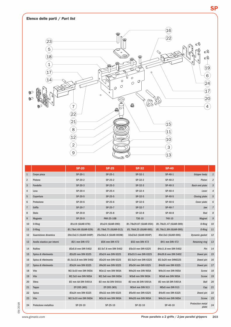
Elenco delle parti / Part list
SP-20 SP-25 SP-32 SP-40
1 Corpo pinza SP-20-1 SP-25-1 SP-32-1 SP-40-1 Gripper body 1
2 Pistone SP-20-2 SP-25-2 SP-32-2 SP-40-2 Piston 2
3 Fondello SP-20-3 SP-25-3 SP-32-3 SP-40-3 Back end plate 3
4 Leva SP-20-4 SP-25-4 SP-32-4 SP-40-4 Lever 4
5 Copertura SP-20-5 SP-25-5 SP-32-5 SP-40-5 Closing plate 5
6 Protezione SP-20-6 SP-25-6 SP-32-6 SP-40-6 Cover plate 6
7 Griffa SP-20-7 SP-25-7 SP-32-7 SP-40-7 Jaw 7
8 Stelo SP-20-8 SP-25-8 SP-32-8 SP-40-8 Rod 8
9 Magnete SP-20-9 PAR-25-10B T30-10 T40-10 Magnet 9
10 O-Ring Ø1x19 (GUAR-078) Ø1x24 (GUAR-090) Ø1.78x29.87 (GUAR-054) Ø1.78x31.47 (GUAR-009) O-Ring 10
11 O-Ring Ø1.78x4.48 (GUAR-029) Ø1.78x6.75 (GUAR-012) Ø1.78x9.25 (GUAR-065) Ø1.78x11.89 (GUAR-095) O-Ring 11
12 Guarnizione dinamica 20x13x2.5 (GUAR-040P) 25x18x2.4 (GUAR-003M) 32x23x3 (GUAR-004P) 40x13x3 (GUAR-006) Dynamic gasket 12
13 Anello elastico per interni Ø21 mm DIN 472 Ø26 mm DIN 472 Ø33 mm DIN 472 Ø41 mm DIN 472 Retaining ring 13
14 Rullino Ø2x5.8 mm DIN 5402 Ø2.5x7.8 mm DIN 5402 Ø3x10 mm DIN 6325 Ø4x11.8 mm DIN 5402 Pin 14
15 Spina di riferimento Ø2x20 mm DIN 6325 Ø3x24 mm DIN 6325 Ø3x33.5 mm DIN 6325 Ø4x39.8 mm DIN 5402 Dowel pin 15
16 Spina di riferimento Ø1.5x13.8 mm DIN 5402 Ø2x20 mm DIN 6325 Ø2.5x24 mm DIN 6325 Ø2.5x20 mm DIN6325 Dowel pin 16
17 Spina di riferimento Ø3x24 mm DIN 6325 Ø4x30 mm DIN 6325 Ø5x36 mm DIN 6325 Ø4x50 mm DIN 6325 Dowel pin 17
18 Vite M2.5x10 mm DIN 965A M3x12 mm DIN 965A M4x20 mm DIN 965A M4x16 mm DIN 965A Screw 18
19 Vite M2.5x5 mm DIN 965A M2.5x6 mm DIN 965A M3x8 mm DIN 965A M3x8 mm DIN 965A Screw 19
20 Sfera Ø2 mm AA DIN 5401A Ø2 mm AA DIN 5401A Ø2 mm AA DIN 5401A Ø2 mm AA DIN 5401A Ball 20
21 Tappo DT-205 (M3) DT-205 (M3) M3x4 mm DIN 913 M5x5 mm DIN 913 Cap 21
22 Spina Ø3x24 mm DIN 6325 Ø4x32 mm DIN 6325 Ø5x40 mm DIN 6325 Ø4x45 mm DIN 6325 Dowel pin 22
23 Vite M2.5x10 mm DIN 965A M3x16 mm DIN 965A M4x20 mm DIN 965A M4x16 mm DIN 965A Screw 23
24 Protezione metallica SP-20-10 SP-25-10 SP-32-10 SP-40-10Protection metal
plate24