Sonde e sensori Probes and sensors - carelparts.com · Guida alla scelta e all'installazione...
76
Integrated Control Solutions & Energy Savings NO POWER & SIGNAL CABLES TOGETHER READ CAREFULLY IN THE TEXT! Probes and sensors Sonde e sensori Selection and optimal installation guide Guida alla scelta e all'installazione ottimale
Transcript of Sonde e sensori Probes and sensors - carelparts.com · Guida alla scelta e all'installazione...

I n t e g r a t e d C o n t r o l S o l u t i o n s & E n e r g y S a v i n g s
NO POWER & SIGNAL CABLES
TOGETHER
READ CAREFULLY IN THE TEXT!
Probes and sensors
Sonde e sensori
Selection and optimal installation guide
Guida alla scelta e all'installazione ottimale

3
ITA
Sonde e sensori: Guida alla scelta e all'installazione ottimale +040010025 rel. 1.0 - 12.11.2015
AVVERTENZE
CAREL basa lo sviluppo dei suoi prodotti su una esperienza pluridecennale nel
campo HVAC, sull’investimento continuo in innovazione tecnologica di prodotto,
su procedure e processi di qualità rigorosi con test in-circuit e funzionali sul 100%
della sua produzione, sulle più innovative tecnologie di produzione disponibili nel
mercato. CAREL e le sue filiali/affiliate non garantiscono tuttavia che tutti gli aspetti
del prodotto e del software incluso nel prodotto risponderanno alle esigenze
dell’applicazione finale, pur essendo il prodotto costruito secondo le tecniche dello
stato dell’arte.
Il cliente (costruttore, progettista o installatore dell’equipaggiamento finale) si
assume ogni responsabilità e rischio in relazione alla configurazione del prodotto
per il raggiungimento dei risultati previsti in relazione all’installazione e/o
equipaggiamento finale specifico.
CAREL in questo caso, previ accordi specifici, può intervenire come consulente per
la buona riuscita dello start-up macchina finale/applicazione, ma in nessun caso
può essere ritenuta responsabile per il buon funzionamento del equipaggiamento/
impianto finale.
Il prodotto CAREL è un prodotto avanzato, il cui funzionamento è specificato nella
documentazione tecnica fornita col prodotto o scaricabile, anche anteriormente
all’acquisto, dal sito internet www.carel.com.
Ogni prodotto CAREL, in relazione al suo avanzato livello tecnologico, necessita di
una fase di qualifica / configurazione / programmazione / commissioning affinché
possa funzionare al meglio per l’applicazione specifica. La mancanza di tale fase di
studio, come indicata nel manuale, può generare malfunzionamenti nei prodotti
finali di cui CAREL non potrà essere ritenuta responsabile.
Soltanto personale qualificato può installare o eseguire interventi di assistenza
tecnica sul prodotto.
Il cliente finale deve usare il prodotto solo nelle modalità descritte nella
documentazione relativa al prodotto stesso.
Senza che ciò escluda la doverosa osservanza di ulteriori avvertenze presenti nel
manuale, si evidenza che è in ogni caso necessario, per ciascun Prodotto di CAREL:
• Evitare che i circuiti elettronici si bagnino. La pioggia, l’umidità e tutti i tipi di
liquidi o la condensa contengono sostanze minerali corrosive che possono
danneggiare i circuiti elettronici. In ogni caso il prodotto va usato o stoccato
in ambienti che rispettano i limiti di temperatura ed umidità specificati nel
manuale.
• Non installare il dispositivo in ambienti particolarmente caldi. Temperature
troppo elevate possono ridurre la durata dei dispositivi elettronici, danneggiarli
e deformare o fondere le parti in plastica. In ogni caso il prodotto va usato o
stoccato in ambienti che rispettano i limiti di temperatura ed umidità specificati
nel manuale.
• Non tentare di aprire il dispositivo in modi diversi da quelli indicati nel manuale.
• Non fare cadere, battere o scuotere il dispositivo, poiché i circuiti interni e i
meccanismi potrebbero subire danni irreparabili.
• Non usare prodotti chimici corrosivi, solventi o detergenti aggressivi per pulire
il dispositivo.
• Non utilizzare il prodotto in ambiti applicativi diversi da quanto specificato nel
manuale tecnico.
Tutti i suggerimenti sopra riportati sono validi altresì per il controllo, schede
seriali, chiavi di programmazione o comunque per qualunque altro accessorio del
portfolio prodotti CAREL.
CAREL adotta una politica di continuo sviluppo. Pertanto CAREL si riserva il diritto
di effettuare modifiche e miglioramenti a qualsiasi prodotto descritto nel presente
documento senza previo preavviso.
I dati tecnici presenti nel manuale possono subire modifiche senza obbligo di
preavviso
La responsabilità di CAREL in relazione al proprio prodotto è regolata dalle condizioni
generali di contratto CAREL editate nel sito www.carel.com e/o da specifici accordi
con i clienti; in particolare, nella misura consentita dalla normativa applicabile, in
nessun caso CAREL, i suoi dipendenti o le sue filiali/affiliate saranno responsabili
di eventuali mancati guadagni o vendite, perdite di dati e di informazioni, costi
di merci o servizi sostitutivi, danni a cose o persone, interruzioni di attività, o
eventuali danni diretti, indiretti, incidentali, patrimoniali, di copertura, punitivi,
speciali o consequenziali in qualunque modo causati, siano essi contrattuali, extra
contrattuali o dovuti a negligenza o altra responsabilità derivanti dall’installazione,
utilizzo o impossibilità di utilizzo del prodotto, anche se CAREL o le sue filiali/affiliate
siano state avvisate della possibilità di danni.
SMALTIMENTO
INFORMAZIONE AGLI UTENTI PER IL CORRETTO TRATTAMENTO DEI RIFIUTI DI APPARECCHIATURE ELETTRICHE ED ELETTRONICHE (RAEE)
In riferimento alla Direttiva 2002/96/CE del Parlamento Europeo e del
Consiglio del 27 gennaio 2003 e alle relative normative nazionali di attuazione,
Vi informiamo che:
1. sussiste l’obbligo di non smaltire i RAEE come rifiuti urbani e di effettuare,
per detti rifiuti, una raccolta separata;
2. Per lo smaltimento vanno utilizzati i sistemi di raccolta pubblici o privati
previsti dalla leggi locali. È inoltre possibile riconsegnare al distributore
l’apparecchiatura a fine vita in caso di acquisto di una nuova;
3. questa apparecchiatura può contenere sostanze pericolose: un uso
improprio o uno smaltimento non corretto potrebbe avere effetti
negativi sulla salute umana e sull’ambiente;
4. il simbolo (contenitore di spazzatura su ruote barrato) riportato
sul prodotto o sulla confezione e sul foglio istruzioni indica che
l’apparecchiatura è stata immessa sul mercato dopo il 13 agosto 2005 e
che deve essere oggetto di raccolta separata;
5. in caso di smaltimento abusivo dei rifiuti elettrici ed elettronici sono
previste sanzioni stabilite dalle vigenti normative locali in materia di
smaltimento.
Garanzia sui materiali: 2 anni (dalla data di produzione, escluse le parti di
consumo).
Omologazioni: la qualità e la sicurezza dei prodotti CAREL INDUSTRIES Hq
sono garantite dal sistema di progettazione e produzione certificato ISO 9001.
ATTENZIONE: separare quanto più possibile i cavi delle sonde e degli ingressi
digitali dai cavi dei carichi induttivi e di potenza per evitare possibili disturbi
elettromagnetici.
Non inserire mai nelle stesse canaline (comprese quelle dei quadri elettrici)
cavi di potenza e cavi di segnale
NO POWER & SIGNAL CABLES
TOGETHER
READ CAREFULLY IN THE TEXT!

4
ITA
Sonde e sensori: Guida alla scelta e all'installazione ottimale +040010025 rel. 1.0 - 12.11.2015
5
ITA
Sonde e sensori: Guida alla scelta e all'installazione ottimale +040010025 rel. 1.0 - 12.11.2015
Indice
1. SENSORI PASSIVI DI TEMPERATURA 7
1.1 Guida alla scelta in base all’applicazione ............................................7
2. CONSIDERAZIONI SULLA TRASMISSIONE DI CALORE
NELLA MISURAZIONE DELLA TEMPERATURA 8
3. SENSORI ATTIVI DI TEMPERATURA E UMIDITÀ 8
4. SENSORI ATTIVI DI QUALITÀ DELL'ARIA 9
5. SENSORI FUGHE GAS REFRIGERANTE
(R22, R134A, R290, R404A, R407C-F, R410A,
R744, ETILENE) 9
6. SENSORI DI PRESSIONE 10
7. SENSORI DIFFERENZIALI DI PRESSIONE 10
8. SENSORI DI ALLAGAMENTO 11
9. SENSORI ANTIGELO 11
10. SENSORI FUMO-FUOCO 11
11. SENSORI DI LIVELLO 11
12. INDICAZIONE DI INSTALLAZIONE PER
CAMPO APPLICATIVO 12
12.1 AHU ...........................................................................................................................12
12.2 HVAC: Chiller/Pompa di calore A/W - W/W .....................................14
12.3 CRAC.........................................................................................................................16
12.4 CRAC CW ...............................................................................................................18
12.5 HVAC: Applicazione raffreddamento tecnologico/di
processo Chiller condensati ad aria/acqua ......................................20
12.6 HVAC: Applicazioni commerciali/residenziali - Roof Top .........22
12.7 Abbattitore ...........................................................................................................24
12.8 Banchi frigo autonomi/Refrigeratore di bevande ........................26
12.9 Banchi frigo autonomi condensati ad acqua .................................28
12.10 Banchi frigo centralizzati/canalizzati ..................................................30
12.11 Cella frigorifera ...................................................................................................32
12.12 Impianto CO2 transcritico ...........................................................................34
12.13 Impianto CO2 Subcritico .............................................................................35
13. ULTERIORI RACCOMANDAZIONI 36
13.1 Sensori di temperatura e umidità ambiente ...................................36
13.2 Sensori temperatura e umidità condotta .........................................37
13.3 Sensori di temperatura .................................................................................38
13.4 Sensori di pressione ........................................................................................38
13.5 Sensori fughe gas .............................................................................................38

6
ITA
Sonde e sensori: Guida alla scelta e all'installazione ottimale +040010025 rel. 1.0 - 12.11.2015
7
ITA
Sonde e sensori: Guida alla scelta e all'installazione ottimale +040010025 rel. 1.0 - 12.11.2015
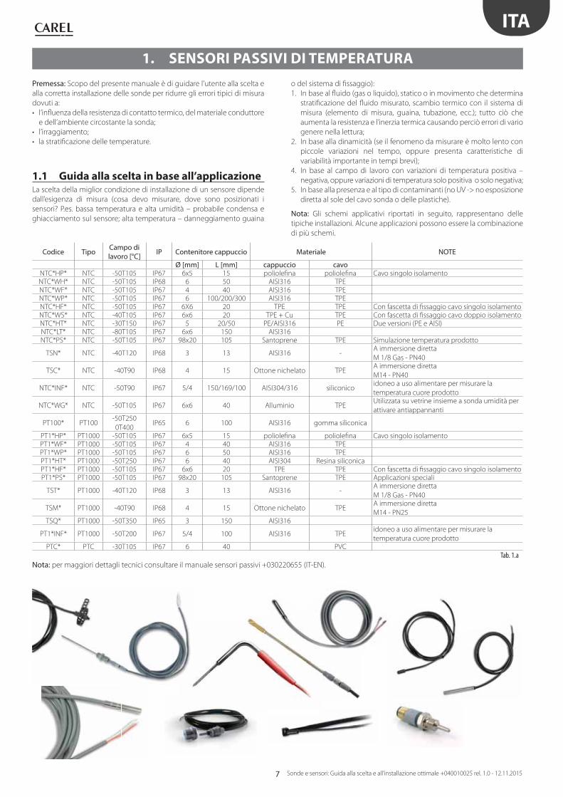
1. SENSORI PASSIVI DI TEMPERATURA
Premessa: Scopo del presente manuale è di guidare l’utente alla scelta e
alla corretta installazione delle sonde per ridurre gli errori tipici di misura
dovuti a:
• l’infl uenza della resistenza di contatto termico, del materiale conduttore
e dell’ambiente circostante la sonda;
• l’irraggiamento;
• la stratifi cazione delle temperature.
1.1 Guida alla scelta in base all’applicazione La scelta della miglior condizione di installazione di un sensore dipende
dall’esigenza di misura (cosa devo misurare, dove sono posizionati i
sensori? P.es. bassa temperatura e alta umidità – probabile condensa e
ghiacciamento sul sensore; alta temperatura – danneggiamento guaina
o del sistema di fi ssaggio):
1. In base al fl uido (gas o liquido), statico o in movimento che determina
stratifi cazione del fl uido misurato, scambio termico con il sistema di
misura (elemento di misura, guaina, tubazione, ecc.); tutto ciò che
aumenta la resistenza e l’inerzia termica causando perciò errori di vario
genere nella lettura;
2. In base alla dinamicità (se il fenomeno da misurare è molto lento con
piccole variazioni nel tempo, oppure presenta caratteristiche di
variabilità importante in tempi brevi);
4. In base al campo di lavoro con variazioni di temperatura positiva –
negativa, oppure variazioni di temperatura solo positiva o solo negativa;
5. In base alla presenza e al tipo di contaminanti (no UV -> no esposizione
diretta al sole del cavo sonda o delle plastiche).
Nota: Gli schemi applicativi riportati in seguito, rappresentano delle
tipiche installazioni. Alcune applicazioni possono essere la combinazione
di più schemi.
Codice Tipo Campo di lavoro [°C] IP Contenitore cappuccio Materiale NOTE
Ø [mm] L [mm] cappuccio cavoNTC*HP* NTC -50T105 IP67 6x5 15 poliolefi na poliolefi na Cavo singolo isolamentoNTC*WH* NTC -50T105 IP68 6 50 AISI316 TPENTC*WF* NTC -50T105 IP67 4 40 AISI316 TPENTC*WP* NTC -50T105 IP67 6 100/200/300 AISI316 TPENTC*HF* NTC -50T105 IP67 6X6 20 TPE TPE Con fascetta di fi ssaggio cavo singolo isolamentoNTC*WS* NTC -40T105 IP67 6x6 20 TPE + Cu TPE Con fascetta di fi ssaggio cavo doppio isolamentoNTC*HT* NTC -30T150 IP67 5 20/50 PE/AISI316 PE Due versioni (PE e AISI)NTC*LT* NTC -80T105 IP67 6x6 150 AISI316NTC*PS* NTC -50T105 IP67 98x20 105 Santoprene TPE Simulazione temperatura prodotto
TSN* NTC -40T120 IP68 3 13 AISI316 -A immersione diretta
M 1/8 Gas - PN40
TSC* NTC -40T90 IP68 4 15 Ottone nichelato TPEA immersione diretta
M14 - PN40
NTC*INF* NTC -50T90 IP67 5/4 150/169/100 AISI304/316 siliconicoidoneo a uso alimentare per misurare la
temperatura cuore prodotto
NTC*WG* NTC -50T105 IP67 6x6 40 Alluminio TPEUtilizzata su vetrine insieme a sonda umidità per
attivare antiappannanti
PT100* PT100-50T250
0T400IP65 6 100 AISI316 gomma siliconica
PT1*HP* PT1000 -50T105 IP67 6x5 15 poliolefi na poliolefi na Cavo singolo isolamentoPT1*WF* PT1000 -50T105 IP67 4 40 AISI316 TPEPT1*WP* PT1000 -50T105 IP67 6 50 AISI316 TPEPT1*HT* PT1000 -50T250 IP67 6 40 AISI304 Resina siliconicaPT1*HF* PT1000 -50T105 IP67 6x6 20 TPE TPE Con fascetta di fi ssaggio cavo singolo isolamentoPT1*PS* PT1000 -50T105 IP67 98x20 105 Santoprene TPE Applicazioni speciali
TST* PT1000 -40T120 IP68 3 13 AISI316 -A immersione diretta
M 1/8 Gas - PN40
TSM* PT1000 -40T90 IP68 4 15 Ottone nichelato TPEA immersione diretta
M14 - PN25TSQ* PT1000 -50T350 IP65 3 150 AISI316
PT1*INF* PT1000 -50T200 IP67 5/4 100 AISI316 TPEidoneo a uso alimentare per misurare la
temperatura cuore prodottoPTC* PTC -30T105 IP67 6 40 PVC
Tab. 1.a
Nota: per maggiori dettagli tecnici consultare il manuale sensori passivi +030220655 (IT-EN).
8
T
Ta
Di
ξ
Treal
Tmeas
Ae 4De=Vi DDi ∏/42
∏
ITA
Sonde e sensori: Guida alla scelta e all'installazione ottimale +040010025 rel. 1.0 - 12.11.2015
2. CONSIDERAZIONI SULLA TRASMISSIONE DI CALORE NELLA
MISURAZIONE DELLA TEMPERATURA
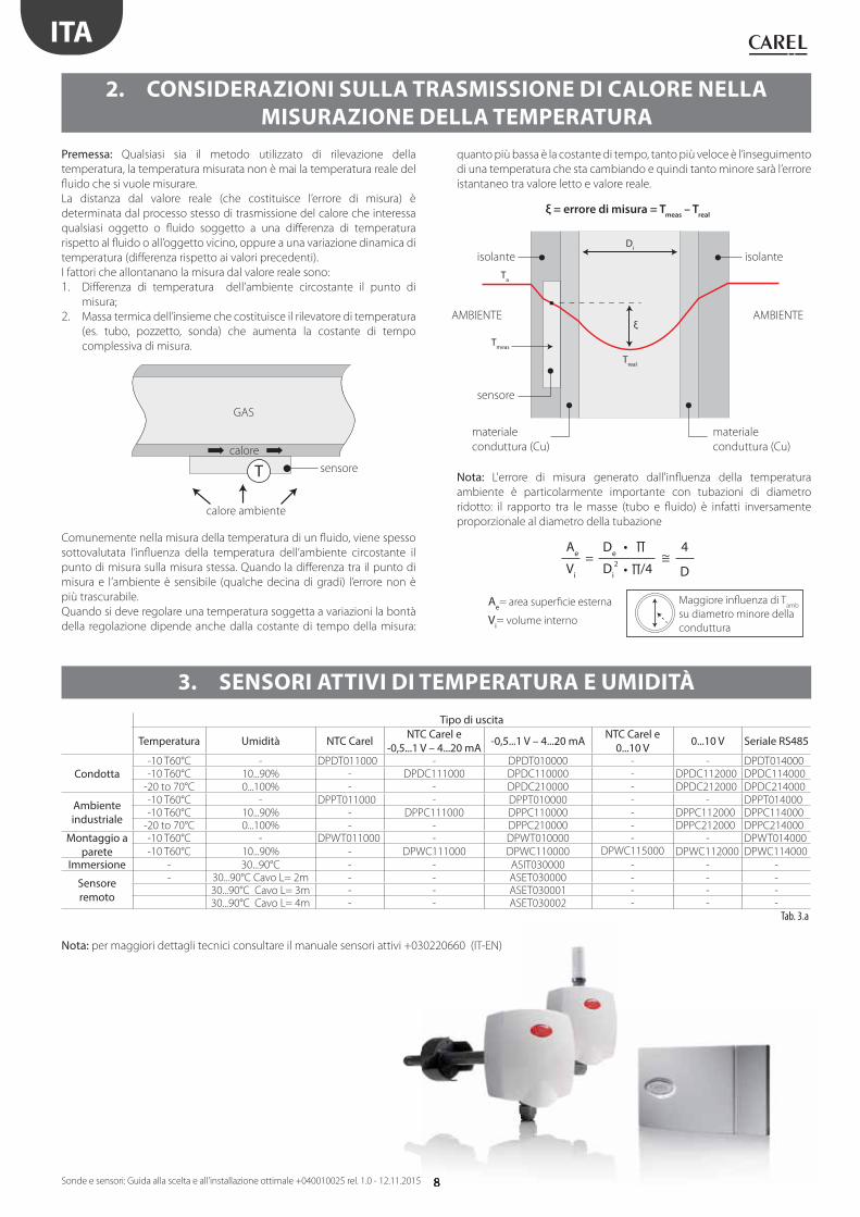
3. SENSORI ATTIVI DI TEMPERATURA E UMIDITÀ
Tipo di uscita
Temperatura Umidità NTC Carel NTC Carel e -0,5...1 V – 4...20 mA -0,5...1 V – 4...20 mA NTC Carel e
0...10 V 0...10 V Seriale RS485
Condotta-10 T60°C - DPDT011000 - DPDT010000 - - DPDT014000-10 T60°C 10...90% - DPDC111000 DPDC110000 - DPDC112000 DPDC114000
-20 to 70°C 0...100% - - DPDC210000 - DPDC212000 DPDC214000
Ambiente industriale
-10 T60°C - DPPT011000 - DPPT010000 - - DPPT014000-10 T60°C 10...90% - DPPC111000 DPPC110000 - DPPC112000 DPPC114000
-20 to 70°C 0...100% - - DPPC210000 - DPPC212000 DPPC214000Montaggio a
parete-10 T60°C - DPWT011000 - DPWT010000 - - DPWT014000
-10 T60°C 10...90% - DPWC111000 DPWC110000 DPWC115000 DPWC112000 DPWC114000
Immersione - 30...90°C - - ASIT030000 - - -
Sensore remoto
- 30...90°C Cavo L= 2m - - ASET030000 - - -30...90°C Cavo L= 3m - - ASET030001 - - -30...90°C Cavo L= 4m - - ASET030002 - - -
Tab. 3.a
Nota: per maggiori dettagli tecnici consultare il manuale sensori attivi +030220660 (IT-EN)
Premessa: Qualsiasi sia il metodo utilizzato di rilevazione della
temperatura, la temperatura misurata non è mai la temperatura reale del
fl uido che si vuole misurare.
La distanza dal valore reale (che costituisce l’errore di misura) è
determinata dal processo stesso di trasmissione del calore che interessa
qualsiasi oggetto o fl uido soggetto a una diff erenza di temperatura
rispetto al fl uido o all’oggetto vicino, oppure a una variazione dinamica di
temperatura (diff erenza rispetto ai valori precedenti).
I fattori che allontanano la misura dal valore reale sono:
1. Diff erenza di temperatura dell’ambiente circostante il punto di
misura;
2. Massa termica dell’insieme che costituisce il rilevatore di temperatura
(es. tubo, pozzetto, sonda) che aumenta la costante di tempo
complessiva di misura.
Comunemente nella misura della temperatura di un fl uido, viene spesso
sottovalutata l’infl uenza della temperatura dell’ambiente circostante il
punto di misura sulla misura stessa. Quando la diff erenza tra il punto di
misura e l’ambiente è sensibile (qualche decina di gradi) l’errore non è
più trascurabile.
Quando si deve regolare una temperatura soggetta a variazioni la bontà
della regolazione dipende anche dalla costante di tempo della misura:
quanto più bassa è la costante di tempo, tanto più veloce è l’inseguimento
di una temperatura che sta cambiando e quindi tanto minore sarà l’errore
istantaneo tra valore letto e valore reale.
Nota: L'errore di misura generato dall'infl uenza della temperatura
ambiente è particolarmente importante con tubazioni di diametro
ridotto: il rapporto tra le masse (tubo e fl uido) è infatti inversamente
proporzionale al diametro della tubazione
ξ = errore di misura = Tmeas
– Treal
Maggiore infl uenza di Tamb
su diametro minore della
condutturaVi= volume interno
Ae= area superfi cie esterna
calore
GAS
sensore
isolante
sensore
materiale
conduttura (Cu)
materiale
conduttura (Cu)
isolante
AMBIENTE AMBIENTE
calore ambiente
9
ITA
Sonde e sensori: Guida alla scelta e all'installazione ottimale +040010025 rel. 1.0 - 12.11.2015
Codici Carel DP*Q*Versione Uscite Codice prodotto Carel
VOC sensore di qualità dell'aria montaggio a parete 0 to 10V – 4 to 20 mA DPWQ306000CO2 sensore di qualità dell'aria montaggio a parete 0 to 10V DPWQ402000VOC + CO2 sensore di qualità dell'aria montaggio a parete 0 to 10V DPWQ502000VOC sensore di qualità dell'aria versione condotta 0 to 10V – 4 to 20 mA DPDQ306000CO2 sensore di qualità dell'aria versione condotta 0 to 10V DPDQ402000VOC + CO2 sensore di qualità dell'aria versione condotta 0 to 10V DPDQ502000
Tab. 4.a
Nota: per maggiori dettagli tecnici consultare i fogli istruzioni dei sensori qualità dell’aria:
VOC VOC + CO2
+050001290 - IT +050001300 - IT
+050001291 - GB +050001301 - GB
+050001292 - FR +050001302 - FR
+050001293 - DE +050001303 - DE
+050001294 - RU +050001304 - RU
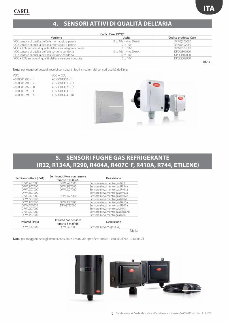
4. SENSORI ATTIVI DI QUALITÀ DELL'ARIA
Semiconduttore (IP41) Semiconduttore con sensore remoto 5 m (IP66) Descrizione
DPWLA07000 DPWLA27000 Sensore rilevamento gas R22DPWLB07000 DPWLB27000 Sensore rilevamento gas R134aDPWLC07000 DPWLC27000 Sensore rilevamento gas R404aDPWLR07000 Sensore rilevamento gas R407aDPWLD07000 DPWLD27000 Sensore rilevamento gas R407cDPWLS07000 Sensore rilevamento gas R407fDPWLE07000 DPWLE27000 Sensore rilevamento gas R410aDPWLT07000 DPWLT27000 Sensore rilevamento gas R507aDPWLG07000 Sensore rilevamento gas NH3DPWLQ07000 Sensore rilevamento gas ETILENEDPWLP07000 Sensore rilevamento gas R290
Infrared (IP66) Infrared con sensore remoto 5 m (IP66) Descrizione
DPWL417000 DPWL427000 Sensore rilevam. gas CO2
Tab. 5.a
Nota: per maggiori dettagli tecnici consultare il manuale specifi co: codice +0300035EN o +0300035IT
5. SENSORI FUGHE GAS REFRIGERANTE
(R22, R134A, R290, R404A, R407C-F, R410A, R744, ETILENE)
10
ITA
Sonde e sensori: Guida alla scelta e all'installazione ottimale +040010025 rel. 1.0 - 12.11.2015
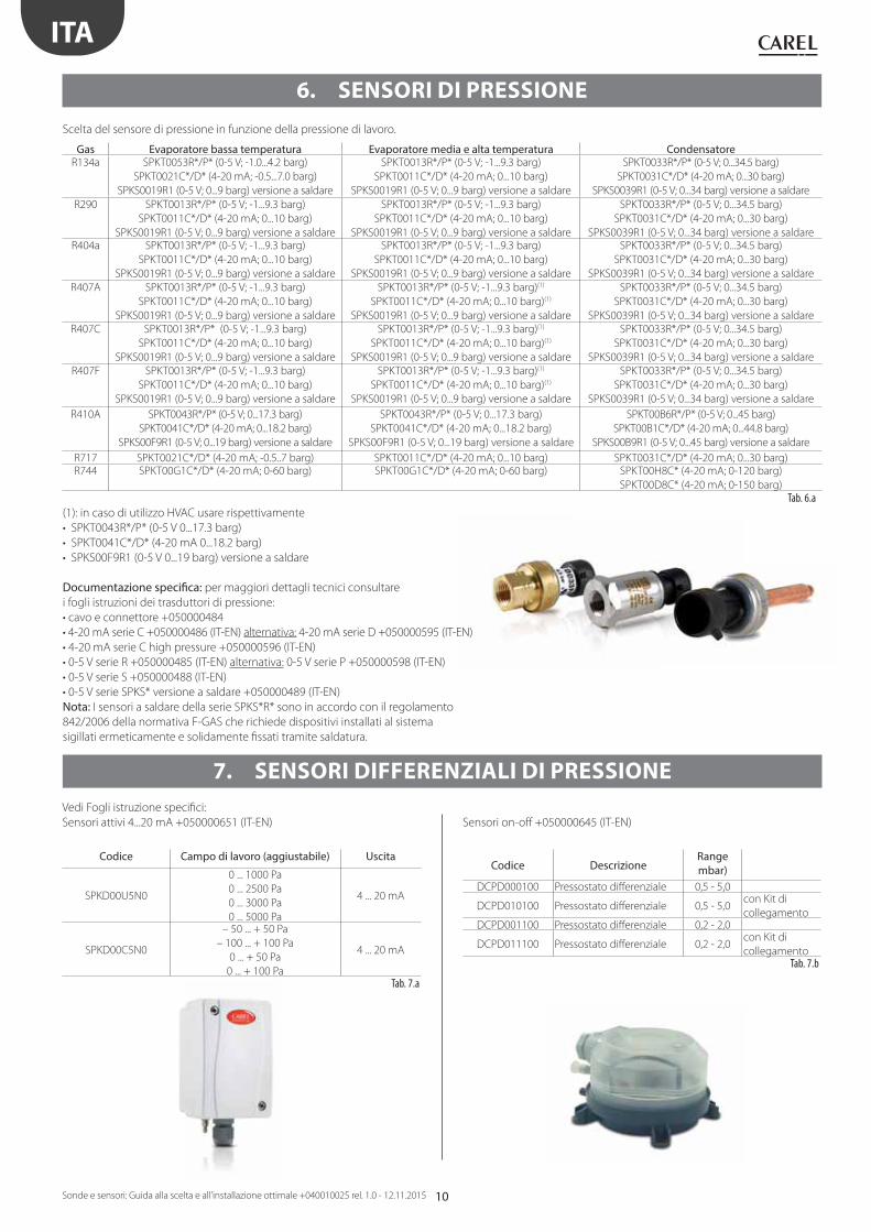
6. SENSORI DI PRESSIONE
Vedi Fogli istruzione specifi ci:
Sensori attivi 4...20 mA +050000651 (IT-EN) Sensori on-off +050000645 (IT-EN)
Codice Campo di lavoro (aggiustabile) Uscita
SPKD00U5N0
0 ... 1000 Pa
0 ... 2500 Pa
0 ... 3000 Pa
0 ... 5000 Pa
4 ... 20 mA
SPKD00C5N0
– 50 ... + 50 Pa
– 100 ... + 100 Pa
0 ... + 50 Pa
0 ... + 100 Pa
4 ... 20 mA
Tab. 7.a
Codice DescrizioneRange mbar)
DCPD000100 Pressostato diff erenziale 0,5 - 5,0
DCPD010100 Pressostato diff erenziale 0,5 - 5,0con Kit di
collegamentoDCPD001100 Pressostato diff erenziale 0,2 - 2,0
DCPD011100 Pressostato diff erenziale 0,2 - 2,0con Kit di
collegamentoTab. 7.b
Scelta del sensore di pressione in funzione della pressione di lavoro.
Gas Evaporatore bassa temperatura Evaporatore media e alta temperatura Condensatore R134a SPKT0053R*/P* (0-5 V; -1.0...4.2 barg)
SPKT0021C*/D* (4-20 mA; -0.5...7.0 barg)
SPKS0019R1 (0-5 V; 0...9 barg) versione a saldare
SPKT0013R*/P* (0-5 V; -1...9.3 barg)
SPKT0011C*/D* (4-20 mA; 0...10 barg)
SPKS0019R1 (0-5 V; 0...9 barg) versione a saldare
SPKT0033R*/P* (0-5 V; 0...34.5 barg)
SPKT0031C*/D* (4-20 mA; 0...30 barg)
SPKS0039R1 (0-5 V; 0...34 barg) versione a saldare
R290 SPKT0013R*/P* (0-5 V; -1...9.3 barg)
SPKT0011C*/D* (4-20 mA; 0...10 barg)
SPKS0019R1 (0-5 V; 0...9 barg) versione a saldare
SPKT0013R*/P* (0-5 V; -1...9.3 barg)
SPKT0011C*/D* (4-20 mA; 0...10 barg)
SPKS0019R1 (0-5 V; 0...9 barg) versione a saldare
SPKT0033R*/P* (0-5 V; 0...34.5 barg)
SPKT0031C*/D* (4-20 mA; 0...30 barg)
SPKS0039R1 (0-5 V; 0...34 barg) versione a saldareR404a SPKT0013R*/P* (0-5 V; -1...9.3 barg)
SPKT0011C*/D* (4-20 mA; 0...10 barg)
SPKS0019R1 (0-5 V; 0...9 barg) versione a saldare
SPKT0013R*/P* (0-5 V; -1...9.3 barg)
SPKT0011C*/D* (4-20 mA; 0...10 barg)
SPKS0019R1 (0-5 V; 0...9 barg) versione a saldare
SPKT0033R*/P* (0-5 V; 0...34.5 barg)
SPKT0031C*/D* (4-20 mA; 0...30 barg)
SPKS0039R1 (0-5 V; 0...34 barg) versione a saldare
R407A SPKT0013R*/P* (0-5 V; -1...9.3 barg)
SPKT0011C*/D* (4-20 mA; 0...10 barg)
SPKS0019R1 (0-5 V; 0...9 barg) versione a saldare
SPKT0013R*/P* (0-5 V; -1...9.3 barg)(1)
SPKT0011C*/D* (4-20 mA; 0...10 barg)(1)
SPKS0019R1 (0-5 V; 0...9 barg) versione a saldare
SPKT0033R*/P* (0-5 V; 0...34.5 barg)
SPKT0031C*/D* (4-20 mA; 0...30 barg)
SPKS0039R1 (0-5 V; 0...34 barg) versione a saldare
R407C SPKT0013R*/P* (0-5 V; -1...9.3 barg)
SPKT0011C*/D* (4-20 mA; 0...10 barg)
SPKS0019R1 (0-5 V; 0...9 barg) versione a saldare
SPKT0013R*/P* (0-5 V; -1...9.3 barg)(1)
SPKT0011C*/D* (4-20 mA; 0...10 barg)(1)
SPKS0019R1 (0-5 V; 0...9 barg) versione a saldare
SPKT0033R*/P* (0-5 V; 0...34.5 barg)
SPKT0031C*/D* (4-20 mA; 0...30 barg)
SPKS0039R1 (0-5 V; 0...34 barg) versione a saldare
R407F SPKT0013R*/P* (0-5 V; -1...9.3 barg)
SPKT0011C*/D* (4-20 mA; 0...10 barg)
SPKS0019R1 (0-5 V; 0...9 barg) versione a saldare
SPKT0013R*/P* (0-5 V; -1...9.3 barg)(1)
SPKT0011C*/D* (4-20 mA; 0...10 barg)(1)
SPKS0019R1 (0-5 V; 0...9 barg) versione a saldare
SPKT0033R*/P* (0-5 V; 0...34.5 barg)
SPKT0031C*/D* (4-20 mA; 0...30 barg)
SPKS0039R1 (0-5 V; 0...34 barg) versione a saldare
R410A SPKT0043R*/P* (0-5 V; 0...17.3 barg)
SPKT0041C*/D* (4-20 mA; 0...18.2 barg)
SPKS00F9R1 (0-5 V; 0...19 barg) versione a saldare
SPKT0043R*/P* (0-5 V; 0...17.3 barg)
SPKT0041C*/D* (4-20 mA; 0...18.2 barg)
SPKS00F9R1 (0-5 V; 0...19 barg) versione a saldare
SPKT00B6R*/P* (0-5 V; 0...45 barg)
SPKT00B1C*/D* (4-20 mA; 0...44.8 barg)
SPKS00B9R1 (0-5 V; 0...45 barg) versione a saldare
R717 SPKT0021C*/D* (4-20 mA; -0.5..7 barg) SPKT0011C*/D* (4-20 mA; 0...10 barg) SPKT0031C*/D* (4-20 mA; 0...30 barg)R744 SPKT00G1C*/D* (4-20 mA; 0-60 barg) SPKT00G1C*/D* (4-20 mA; 0-60 barg) SPKT00H8C* (4-20 mA; 0-120 barg)
SPKT00D8C* (4-20 mA; 0-150 barg)
Tab. 6.a
(1): in caso di utilizzo HVAC usare rispettivamente
• SPKT0043R*/P* (0-5 V 0...17.3 barg)
• SPKT0041C*/D* (4-20 mA 0...18.2 barg)
• SPKS00F9R1 (0-5 V 0...19 barg) versione a saldare
Documentazione specifi ca: per maggiori dettagli tecnici consultare
i fogli istruzioni dei trasduttori di pressione:
• cavo e connettore +050000484
• 4-20 mA serie C +050000486 (IT-EN) alternativa: 4-20 mA serie D +050000595 (IT-EN)
• 4-20 mA serie C high pressure +050000596 (IT-EN)
• 0-5 V serie R +050000485 (IT-EN) alternativa: 0-5 V serie P +050000598 (IT-EN)
• 0-5 V serie S +050000488 (IT-EN)
• 0-5 V serie SPKS* versione a saldare +050000489 (IT-EN)
Nota: I sensori a saldare della serie SPKS*R* sono in accordo con il regolamento
842/2006 della normativa F-GAS che richiede dispositivi installati al sistema
sigillati ermeticamente e solidamente fi ssati tramite saldatura.
7. SENSORI DIFFERENZIALI DI PRESSIONE
11
ITA
Sonde e sensori: Guida alla scelta e all'installazione ottimale +040010025 rel. 1.0 - 12.11.2015
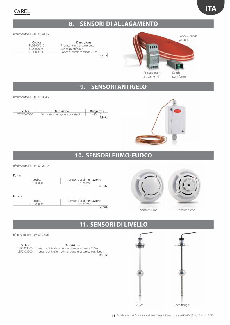
8. SENSORI DI ALLAGAMENTO
9. SENSORI ANTIGELO
10. SENSORI FUMO-FUOCO
11. SENSORI DI LIVELLO
riferimento F.I. +050004116
riferimento F.I. +050000646
riferimento F.I. +050000520
riferimento F.I. +0500075ML
Codice DescrizioneFLOE000010 Rilevatore anti allagamentoFLOS000000 Sonda puntiformeFLOR000000 Sonda a banda sensibile 25 m
Tab. 8.a
Codice Descrizione Range (°C)DCTF000320 Termostato antigelo monostadio -10...15
Tab. 9.a
FumoCodice Tensione di alimentazione
SFFS000000 12...24 VdcTab. 10.a
FuocoCodice Tensione di alimentazione
SFFF000000 12...24 VdcTab. 10.b
Codice DescrizioneLSR0013000 Sensore di livello – connessione meccanica 2” GasLSR0023000 Sensore di livello – connessione meccanica con fl angia
Tab. 11.a
Sensore fumo
Sonda a banda
sensibile
Sonda
puntiforme
Rilevatore anti
allagamento
2" Gas
Sensore fuoco
con fl angia
12
ΔP
– +
– +
T rH%
T
T
T
rH%
ΔP
T
ITA
Sonde e sensori: Guida alla scelta e all'installazione ottimale +040010025 rel. 1.0 - 12.11.2015
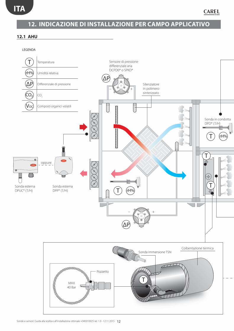
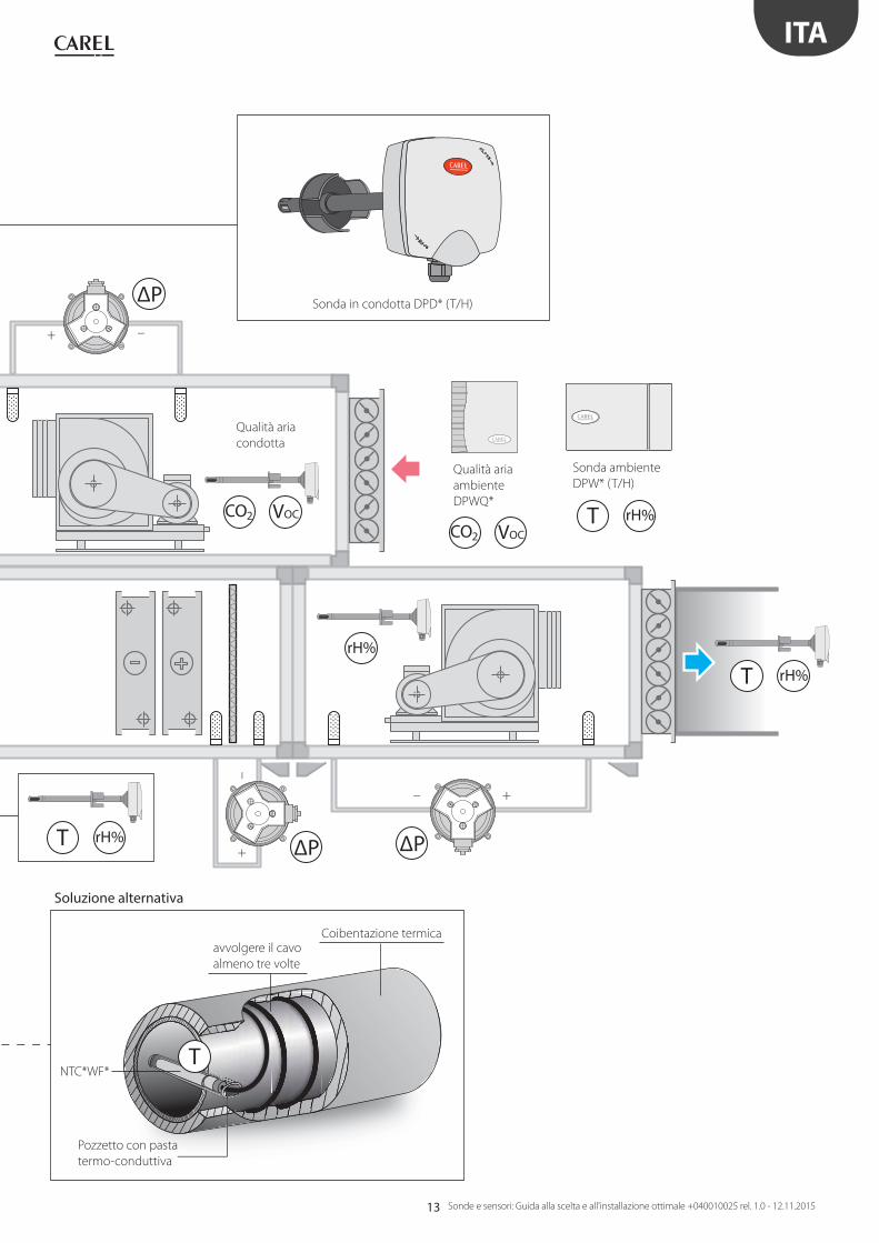
LEGENDA
T Temperatura
rH% Umidità relativa
ΔP Diff erenziale di pressione
CO2 CO2
VOC Composti organici volatili
Sensore di pressione
diff erenziale aria
DCPD0* o SPKD*
Silenziatore
in polimero
sinterizzato
oppure
Sonda esterna
DPUC* (T/H)
Sonda esterna
DPP* (T/H)
Coibentazione termica
Sonda in condotta
DPD* (T/H)
Sonda immersione TSN
Pozzetto
12. INDICAZIONE DI INSTALLAZIONE PER CAMPO APPLICATIVO
12.1 AHU
MAX
40 Bar
13
ΔP
ΔP ΔP
VOCCO2
VOCCO2
– +
–+
+ –
T rH%
T rH%
rH%
T rH%
T
ITA
Sonde e sensori: Guida alla scelta e all'installazione ottimale +040010025 rel. 1.0 - 12.11.2015
NTC*WF*
Pozzetto con pasta
termo-conduttiva
avvolgere il cavo
almeno tre volte
Coibentazione termica
Soluzione alternativa
Sonda in condotta DPD* (T/H)
Qualità aria
condotta
Qualità aria
ambiente
DPWQ*
Sonda ambiente
DPW* (T/H)

14
T
T
T
T T P
T
T
T
X = 10 D
D
ITA
Sonde e sensori: Guida alla scelta e all'installazione ottimale +040010025 rel. 1.0 - 12.11.2015
12.2 HVAC: Chiller/Pompa di calore A/W - W/W
LEGENDA
T Temperatura
P Pressione
Temperatura
liquido
NTC*WF*
aspirazione
scarico
avvolgere il cavo
almeno tre volte
Coibentazione termica
Compressore BLDC
Temperatura
evaporazione
Temperatura
aspirazione
Pozzetto con pasta
termo-conduttiva
Pozzetto
Coibentazione termicaSonda immersione TSN
MAX
40 Bar
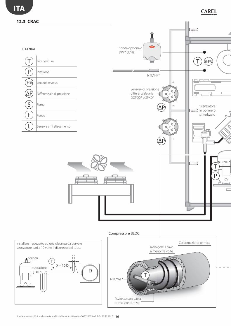
Installare il pozzetto ad una distanza da curve e
strozzature pari a 10 volte il diametro del tubo.
Pressione di
evaporazione

15
T
T
P
P
T
T
P
P
T
T
Ø ≤ 16 mm T Ø > 16 mm
ITA
Sonde e sensori: Guida alla scelta e all'installazione ottimale +040010025 rel. 1.0 - 12.11.2015
Temperatura
condensazione
Pressione
condensazione
NTC*HT*Temperatura
di scarico
Coibentazione termica
Posizione del sensore T temperatura aspirazione
SPKT*P*;
SPKT*S*
SPKT*R*;SPKT*C*;
SPKT*D*
SPKS*R*
NTC*HF*;
NTC*WS* NTC*WF*
avvolgere il cavo
almeno due volte
Nota: Sensore posizionato prima del
sottoraff reddamento e coibentato
Nota: in presenza di
vibrazioni fi ssare il cavo
alla tubazione, in modo
da garantire longevità alla
connessione elettrica.
(vedi pag. 38 Fig. 13.u)
Nota: in presenza di vibrazioni fi ssare il cavo alla tubazione,
in modo da garantire longevità alla connessione elettrica.
(vedi pag. 38 Fig. 13.t)
Compressore ON/OFF
Collegamento con capillare
Pasta termo-conduttiva
3 fascette di fi ssaggio
Collegamento a saldare
avvolgere il cavo
almeno tre volte
NTC*HT*;
NTC*WF*
avvolgere il cavo
almeno due volte
16
T rH%
ΔP –
–
+
+ΔP
T
TX = 10 D
D
T
P
ITA
Sonde e sensori: Guida alla scelta e all'installazione ottimale +040010025 rel. 1.0 - 12.11.2015
12.3 CRAC
LEGENDA
T Temperatura
P Pressione
rH% Umidità relativa
ΔP Diff erenziale di pressione
S Fumo
F Fuoco
L Sensore anti allagamento
NTC*WF*
avvolgere il cavo
almeno tre volte
Coibentazione termica
Silenziatore
in polimero
sinterizzato
Sonda opzionale
DPP* (T/H)
NTC*HP*
Compressore BLDC
Pozzetto con pasta
termo-conduttiva
Sensore di pressione
diff erenziale aria
DCPD0* o SPKD*
aspirazione
scarico
Installare il pozzetto ad una distanza da curve e
strozzature pari a 10 volte il diametro del tubo.
NTC*HT*
17
T rH%
S F
T
T
Ø ≤ 16 mm T Ø > 16 mm
TP
L
P
P
P
ITA
Sonde e sensori: Guida alla scelta e all'installazione ottimale +040010025 rel. 1.0 - 12.11.2015
avvolgere il cavo
almeno tre volte
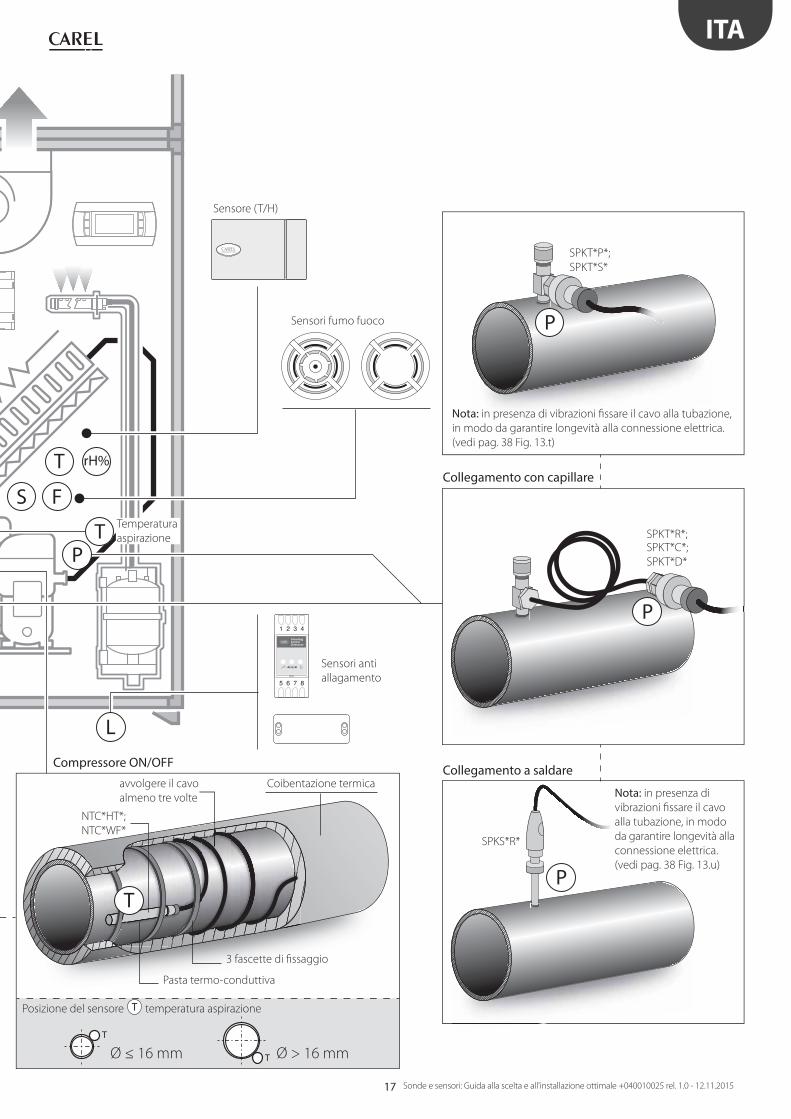
Sensore (T/H)
Sensori fumo fuoco
Coibentazione termica
NTC*HT*;
NTC*WF*
Compressore ON/OFF
Pasta termo-conduttiva
Collegamento con capillare
Collegamento a saldare
3 fascette di fi ssaggio
SPKT*R*;SPKT*C*;
SPKT*D*
SPKS*R*
Posizione del sensore T temperatura aspirazione
Sensori anti
allagamento
SPKT*P*;
SPKT*S*
Nota: in presenza di
vibrazioni fi ssare il cavo
alla tubazione, in modo
da garantire longevità alla
connessione elettrica.
(vedi pag. 38 Fig. 13.u)
Nota: in presenza di vibrazioni fi ssare il cavo alla tubazione,
in modo da garantire longevità alla connessione elettrica.
(vedi pag. 38 Fig. 13.t)
Temperatura
aspirazione

18
T rH%
S
ΔP –
–
+
+ΔP
T
T
ITA
Sonde e sensori: Guida alla scelta e all'installazione ottimale +040010025 rel. 1.0 - 12.11.2015
12.4 CRAC CW
LEGENDA
T Temperatura
rH% Umidità relativa
ΔP Diff erenziale di pressione
S Fumo
F Fuoco
L Sensore anti allagamento
Silenziatore in
polimero sinterizzato
Sonda opzionale
DPP* (T/H)
NTC*HP*
Coibentazione termicaSonda immersione TSN
Pozzetto
Sonda di regolazione
MAX
40 Bar
Sensore di pressione
diff erenziale aria
DCPD0* o SPKD*

19
T rH%
L
F
T
T
T
ITA
Sonde e sensori: Guida alla scelta e all'installazione ottimale +040010025 rel. 1.0 - 12.11.2015
avvolgere il cavo
almeno tre volte
Coibentazione termica
Nota: prevedere coibentazione termica
NTC*WF*
Sensore (T/H)
Sensori anti allagamento
Sensori fumo fuoco
Pasta termo-conduttiva
1a soluzione alternativa - Sonda di lettura 2a soluzione alternativa - Sonda di lettura
3 fascette di fi ssaggio
NTC*HF*;
NTC*WS*
avvolgere il cavo
almeno due volte
20
T
TT
T
T T
P
T
ITA
Sonde e sensori: Guida alla scelta e all'installazione ottimale +040010025 rel. 1.0 - 12.11.2015
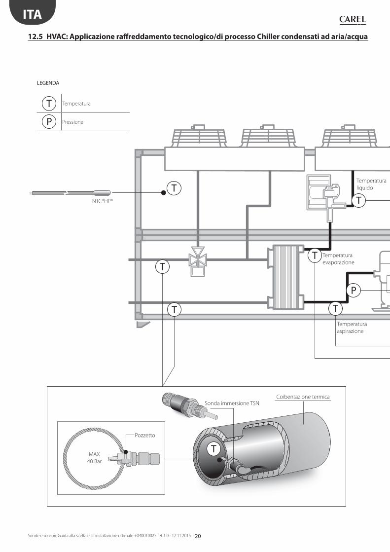
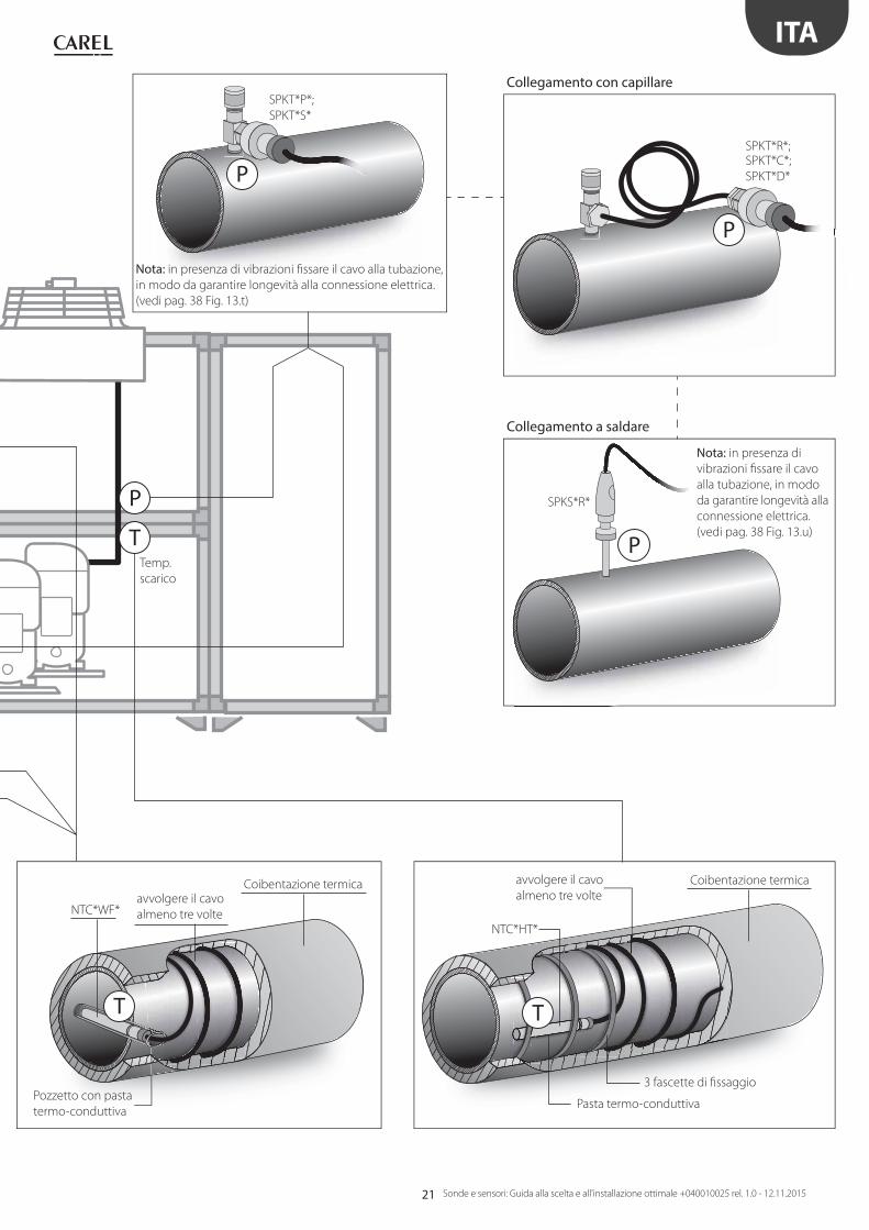
12.5 HVAC: Applicazione raff reddamento tecnologico/di processo Chiller condensati ad aria/acqua
LEGENDA
T Temperatura
P Pressione
Temperatura
aspirazione
Temperatura
liquido
Temperatura
evaporazione
Coibentazione termicaSonda immersione TSN
Pozzetto
MAX
40 Bar
NTC*HP*
21
T
P
T
P
P
P
T
ITA
Sonde e sensori: Guida alla scelta e all'installazione ottimale +040010025 rel. 1.0 - 12.11.2015
NTC*WF*avvolgere il cavo
almeno tre volte
Coibentazione termica
Temp.
scarico
Pozzetto con pasta
termo-conduttiva
Collegamento con capillare
Collegamento a saldare
SPKT*R*;SPKT*C*;
SPKT*D*
SPKS*R*
SPKT*P*;
SPKT*S*
Nota: in presenza di
vibrazioni fi ssare il cavo
alla tubazione, in modo
da garantire longevità alla
connessione elettrica.
(vedi pag. 38 Fig. 13.u)
Nota: in presenza di vibrazioni fi ssare il cavo alla tubazione,
in modo da garantire longevità alla connessione elettrica.
(vedi pag. 38 Fig. 13.t)
avvolgere il cavo
almeno tre volte
Coibentazione termica
NTC*HT*
Pasta termo-conduttiva
3 fascette di fi ssaggio
22
ΔP
–+
ΔP
–+
T
T rH%
T
T
T
ITA
Sonde e sensori: Guida alla scelta e all'installazione ottimale +040010025 rel. 1.0 - 12.11.2015
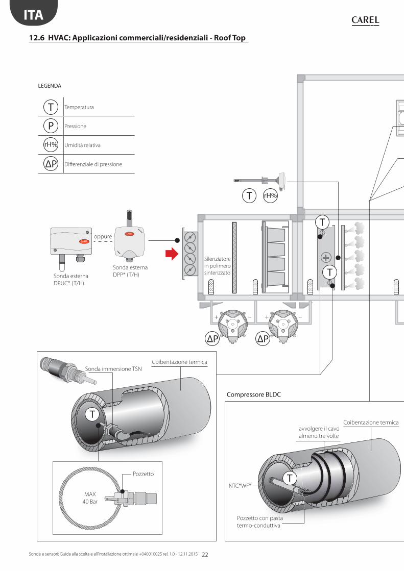
12.6 HVAC: Applicazioni commerciali/residenziali - Roof Top
LEGENDA
T Temperatura
P Pressione
rH% Umidità relativa
ΔP Diff erenziale di pressione
avvolgere il cavo
almeno tre volte
Coibentazione termica
Compressore BLDC
Silenziatore
in polimero
sinterizzato
oppure
Sonda esterna
DPP* (T/H)Sonda esterna
DPUC* (T/H)
Pozzetto con pasta
termo-conduttiva
Pozzetto
Coibentazione termica
Sonda immersione TSN
MAX
40 Bar
NTC*WF*

23
ΔP ΔP
– +–+
rH%
T rH%
T
T
TP
P
T
PP
T
T
Ø ≤ 16 mm T Ø > 16 mm
T
T
T
P
ITA
Sonde e sensori: Guida alla scelta e all'installazione ottimale +040010025 rel. 1.0 - 12.11.2015
Temperatura
evaporazione
Temperatura
aspirazione
avvolgere il cavo
almeno tre volte
Coibentazione termica
NTC*HT*
Compressore ON/OFF
Sonda in condotta DPD* (T/H)
Temperatura
liquido
Pasta termo-conduttiva
Collegamento con capillare Collegamento a saldare
3 fascette di fi ssaggio
SPKT*R*;SPKT*C*;
SPKT*D* SPKS*R*
Sensore di pressione
diff erenziale aria
DCPD0* o SPKD*
Posizione del sensore T temperatura aspirazione
SPKT*P*;
SPKT*S*
Nota: in presenza di vibrazioni fi ssare il cavo alla tubazione,
in modo da garantire longevità alla connessione elettrica.
(vedi pag. 38 Fig. 13.t e 13.u)
NTC*HF*;
NTC*WS*
NTC*WF*
avvolgere il cavo
almeno due volte
avvolgere il cavo
almeno due volte
Nota: Sensore posizionato prima del
sottoraff reddamento e coibentato
Temperatura
condensazione
24
T rH%
P
P
TT
T
T
Ø ≤ 16 mm T Ø > 16 mm
ITA
Sonde e sensori: Guida alla scelta e all'installazione ottimale +040010025 rel. 1.0 - 12.11.2015
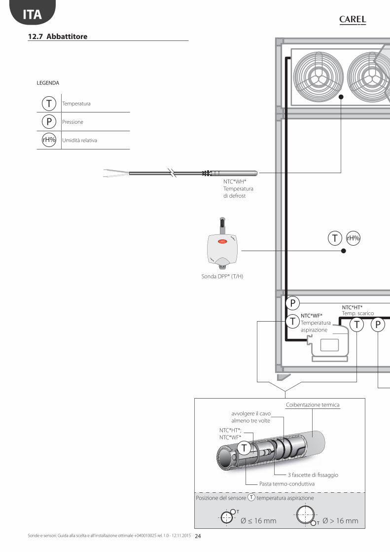
12.7 Abbattitore
NTC*WH*
Temperatura
di defrost
avvolgere il cavo
almeno tre volte
Coibentazione termica
LEGENDA
T Temperatura
P Pressione
rH% Umidità relativa
Pasta termo-conduttiva
3 fascette di fi ssaggio
NTC*WF* Temperatura
aspirazione
NTC*HT* Temp. scarico
Sonda DPP* (T/H)
Posizione del sensore T temperatura aspirazione
NTC*HT*;
NTC*WF*
25
T
T
T P
P P
ITA
Sonde e sensori: Guida alla scelta e all'installazione ottimale +040010025 rel. 1.0 - 12.11.2015
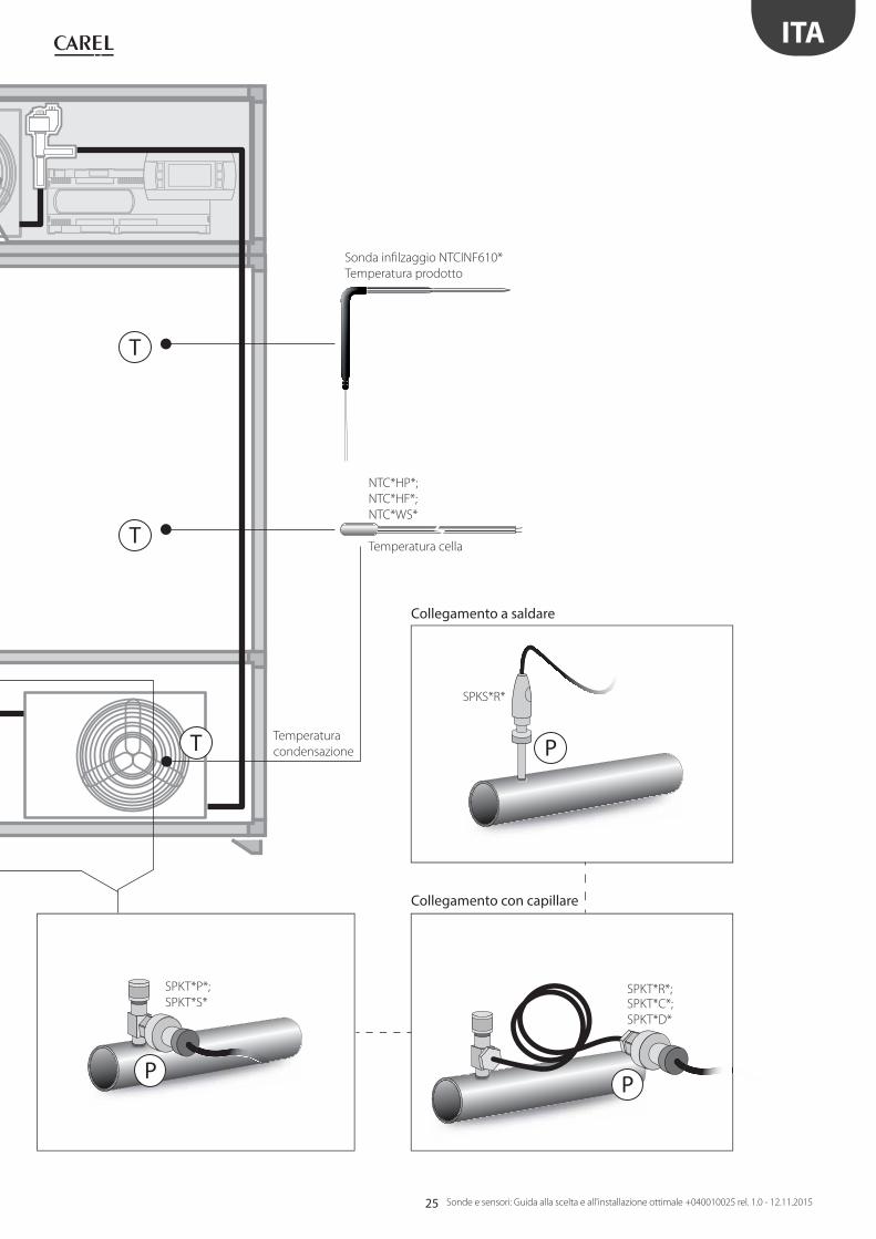
NTC*HP*;
NTC*HF*;
NTC*WS*
Temperatura cella
Sonda infi lzaggio NTCINF610*
Temperatura prodotto
Temperatura
condensazione
Collegamento con capillare
Collegamento a saldare
SPKT*R*;SPKT*C*;
SPKT*D*
SPKS*R*
SPKT*P*;
SPKT*S*
26
T
P
P
T
Ø ≤ 16 mm T Ø > 16 mm
P
T
ITA
Sonde e sensori: Guida alla scelta e all'installazione ottimale +040010025 rel. 1.0 - 12.11.2015
LEGENDA
T Temperatura
P Pressione
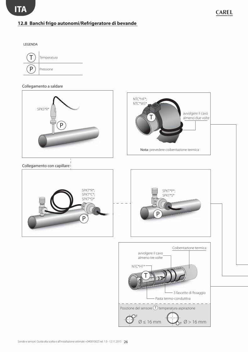
12.8 Banchi frigo autonomi/Refrigeratore di bevande
avvolgere il cavo
almeno tre volte
Coibentazione termica
Pasta termo-conduttiva
Collegamento con capillare
Collegamento a saldare
SPKT*R*;SPKT*C*;
SPKT*D*
SPKS*R*
3 fascette di fi ssaggio
Posizione del sensore T temperatura aspirazione
SPKT*P*;
SPKT*S*
NTC*HT*
Nota: prevedere coibentazione termica
NTC*HF*;
NTC*WS*
avvolgere il cavo
almeno due volte

27
T
T
T
T
T
P
T
T
ITA
Sonde e sensori: Guida alla scelta e all'installazione ottimale +040010025 rel. 1.0 - 12.11.2015
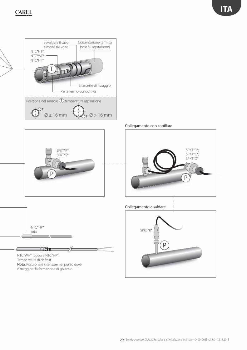
NTC*WH*
Temperatura di defrost
Nota: Posizionare il sensore nel punto dove
è maggiore la formazione di ghiaccio
NTC*HP*
Aria
NTC*PS*
Simulazione
temperatura
prodotto
Temperatura
scarico
Temperatura
aspirazione
28
T
P
TT
T
TP
T rH%
T
T
ITA
Sonde e sensori: Guida alla scelta e all'installazione ottimale +040010025 rel. 1.0 - 12.11.2015
12.9 Banchi frigo autonomi condensati ad acqua
LEGENDA
T Temperatura
rH% Umidità relativa
P Pressione
NTC*HF*Temp.
aspirazione
NTC*HT*Temp. scarico
NTC*WF*
NTC*WF*
Sonda DPW*
ambiente
29
T
Ø ≤ 16 mm T Ø > 16 mm
T
P
PP
ITA
Sonde e sensori: Guida alla scelta e all'installazione ottimale +040010025 rel. 1.0 - 12.11.2015
NTC*WH* (oppure NTC*HP*)
Temperatura di defrost
Nota: Posizionare il sensore nel punto dove
è maggiore la formazione di ghiaccio
avvolgere il cavo
almeno tre volte
Coibentazione termica
(solo su aspirazione)
NTC*HT*;
NTC*WF*;
NTC*HF*
NTC*HP*
Aria
Pasta termo-conduttiva
Collegamento con capillare
Collegamento a saldare
SPKT*R*;SPKT*C*;
SPKT*D*
SPKS*R*
3 fascette di fi ssaggio
Posizione del sensore T temperatura aspirazione
SPKT*P*;
SPKT*S*
30
T
P
P
T
Ø ≤ 16 mm T Ø > 16 mm
P
ITA
Sonde e sensori: Guida alla scelta e all'installazione ottimale +040010025 rel. 1.0 - 12.11.2015
LEGENDA
T Temperatura
P Pressione
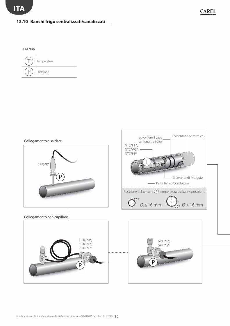
12.10 Banchi frigo centralizzati/canalizzati
avvolgere il cavo
almeno tre volte
Coibentazione termica
NTC*HF*;
NTC*WS*;
NTC*HP*
Pasta termo-conduttiva
Collegamento con capillare
Collegamento a saldare
SPKT*R*;SPKT*C*;
SPKT*D*
SPKS*R*
3 fascette di fi ssaggio
Posizione del sensore T temperatura uscita evaporazione
SPKT*P*;
SPKT*S*

31
T
P
T
T
T
T
ITA
Sonde e sensori: Guida alla scelta e all'installazione ottimale +040010025 rel. 1.0 - 12.11.2015
NTC*HP*
Aria
NTC*PS*
Simulazione
temperatura
prodotto
Pressione
evaporazione
Temp. uscita
evaporazione
NTC*WH*
Temperatura di defrost
Nota: Posizionare il sensore nel punto dove
è maggiore la formazione di ghiaccio

32
T
T
T
rH%
T
T
Ø ≤ 16 mm T Ø > 16 mm
ITA
Sonde e sensori: Guida alla scelta e all'installazione ottimale +040010025 rel. 1.0 - 12.11.2015
12.11 Cella frigorifera
NTC*PS*
Simulazione
temperatura
prodotto
NTC*HP*
Temperatura cella
Sonda DPP*
Temperatura + umidità cella
avvolgere il cavo
almeno tre volte
Coibentazione termica
NTC*WH*
LEGENDA
T Temperatura
P Pressione
rH% Umidità relativa
Pasta termo-conduttiva
3 fascette di fi ssaggio
Posizione del sensore T temperatura uscita evaporazione
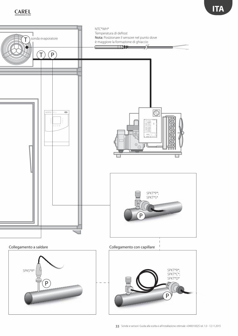
33
PT
N L
18 1
9 20
13 1
4 15
10
11
127
8
91
2
16 1
75
63
4
T
P
P
P
ITA
Sonde e sensori: Guida alla scelta e all'installazione ottimale +040010025 rel. 1.0 - 12.11.2015
sonda evaporatore
Collegamento con capillareCollegamento a saldare
SPKT*R*;SPKT*C*;
SPKT*D*
SPKS*R*
SPKT*P*;
SPKT*S*
NTC*WH*
Temperatura di defrost
Nota: Posizionare il sensore nel punto dove
è maggiore la formazione di ghiaccio
34
P
T
P
T
PT
T
P
T
T
T
CO2
T
T
Ø ≤ 16 mm T Ø > 16 mm
P
T P
ITA
Sonde e sensori: Guida alla scelta e all'installazione ottimale +040010025 rel. 1.0 - 12.11.2015
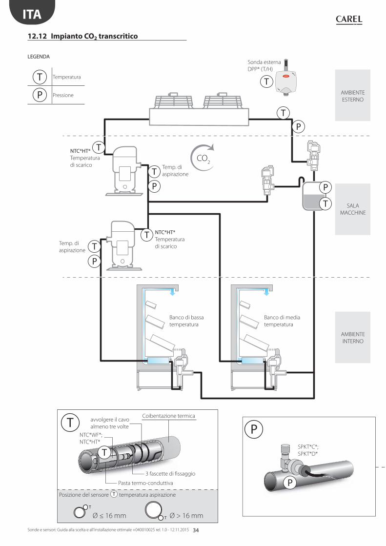
12.12 Impianto CO2 transcritico
Banco di media
temperatura
Banco di bassa
temperatura
LEGENDA
T Temperatura
P Pressione
avvolgere il cavo
almeno tre volte
Coibentazione termica
Pasta termo-conduttiva
3 fascette di fi ssaggio
Sonda esterna
DPP* (T/H)
Posizione del sensore T temperatura aspirazione
Temp. di
aspirazione
AMBIENTE
ESTERNO
SALA
MACCHINE
AMBIENTE
INTERNO
Temp. di
aspirazione
NTC*HT*Temperatura
di scarico
NTC*HT*Temperatura
di scarico
NTC*WF*;
NTC*HT*SPKT*C*;
SPKT*D*
35
T
P
T
P
T
P
T
R134a
CO2
P
T
PT
T
P
P
P P
ITA
Sonde e sensori: Guida alla scelta e all'installazione ottimale +040010025 rel. 1.0 - 12.11.2015
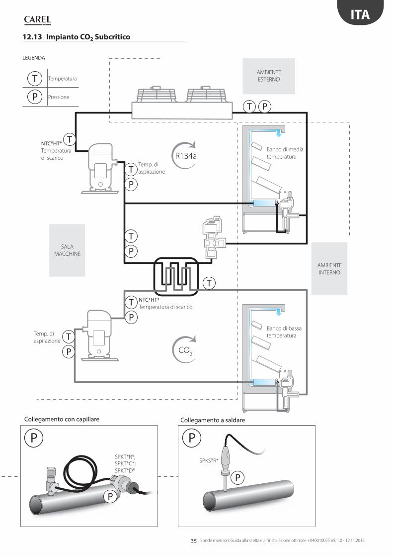
12.13 Impianto CO2 Subcritico
Banco di media
temperatura
Banco di bassa
temperatura
LEGENDA
T Temperatura
P Pressione
Collegamento con capillare
SPKT*R*;SPKT*C*;
SPKT*D*
Collegamento a saldare
SPKS*R*
AMBIENTE
INTERNO
Temp. di
aspirazione
Temp. di
aspirazione
AMBIENTE
ESTERNO
SALA
MACCHINE
NTC*HT*Temperatura
di scarico
NTC*HT*Temperatura di scarico
36
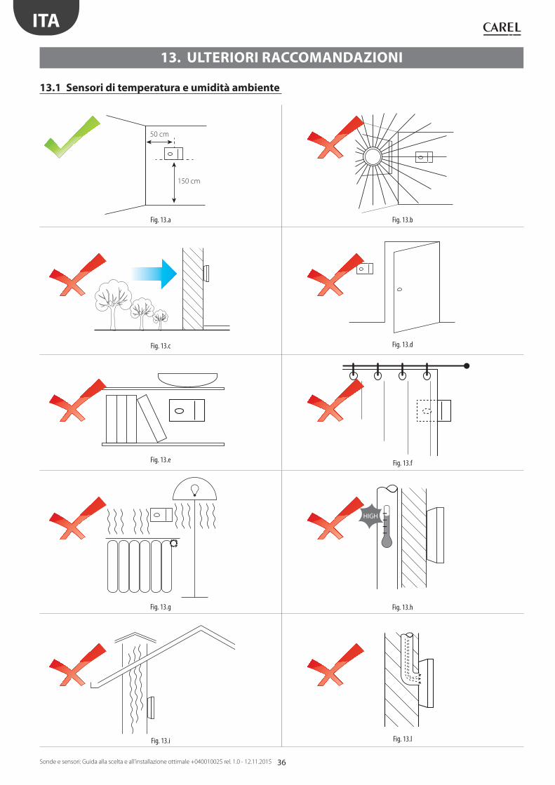
50 cm
150 cm
Fig. 13.a Fig. 13.b
Fig. 13.c Fig. 13.d
Fig. 13.e Fig. 13.f
Fig. 13.g
HIGH
Fig. 13.h
Fig. 13.i Fig. 13.l
ITA
Sonde e sensori: Guida alla scelta e all'installazione ottimale +040010025 rel. 1.0 - 12.11.2015
13. ULTERIORI RACCOMANDAZIONI
13.1 Sensori di temperatura e umidità ambiente
37
Bm
rH%
8
1 21,9 3 4 5 6 7 8 9 10
2
3
4
5
6
7
8
9
9
10
11
12
13
14
15
16
7 6 5 4 3
Fig. 13.m Fig. 13.n
Fig. 13.o
ITA
Sonde e sensori: Guida alla scelta e all'installazione ottimale +040010025 rel. 1.0 - 12.11.2015
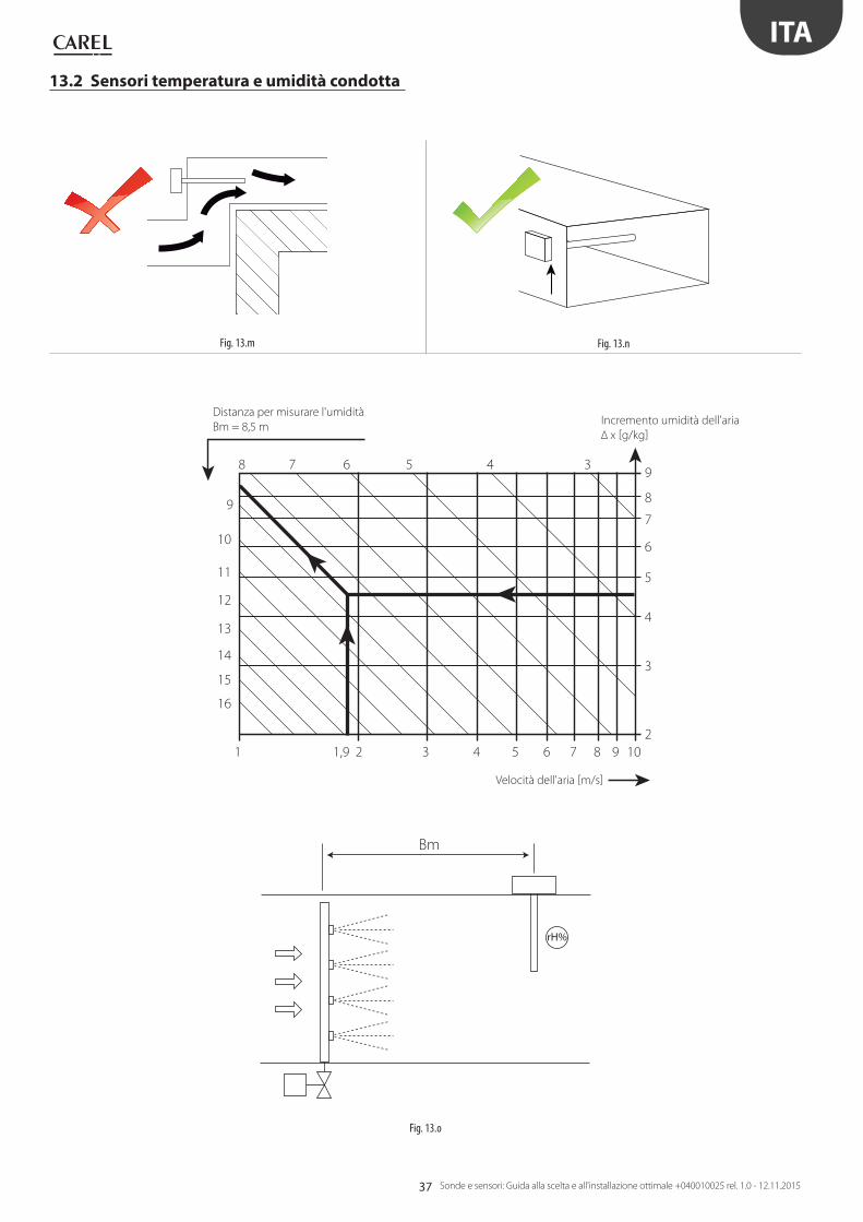
Distanza per misurare l'umidità
Bm = 8,5 m
Velocità dell'aria [m/s]
Incremento umidità dell'aria
Δ x [g/kg]
13.2 Sensori temperatura e umidità condotta

38
d
d
Fig. 13.p
HIGH
LOW
rH%
Fig. 13.q
360°OK
Fig. 13.r
>100 mm
Fig. 13.s
Fig. 13.v
Fig. 13.t Fig. 13.u
ITA
Sonde e sensori: Guida alla scelta e all'installazione ottimale +040010025 rel. 1.0 - 12.11.2015
Sigillare con silicone
Distanza tra punto di
miscelazione e sensore 10 x d
Distanza tra punto di
miscelazione e sensore 10 x d
13.3 Sensori di temperatura
13.4 Sensori di pressione
13.5 Sensori fughe gas
30 cm
30 cm
R22; R407c; NH3;
R134a; R407f; R290;
R404a; R410a; CO2.
R407a; R507a;
ETILENE
3
ENG
Probes and sensors: Selection and optimal installation guide +040010025 rel. 1.0 - 12.11.2015
WARNING
CAREL bases the development of its products on decades of experience in
HVAC, on the continuous investments in technological innovations to products,
procedures and strict quality processes with in-circuit and functional testing on
100% of its products, and on the most innovative production technology available
on the market. CAREL and its subsidiaries nonetheless cannot guarantee that all
the aspects of the product and the software included with the product respond
to the requirements of the final application, despite the product being developed
according to start-of-the-art techniques.
The customer (manufacturer, developer or installer of the final equipment) accepts
all liability and risk relating to the configuration of the product in order to reach
the expected results in relation to the specific final installation and/or equipment.
CAREL may, based on specific agreements, act as a consultant for the positive
commissioning of the final unit/application, however in no case does it accept
liability for the correct operation of the final equipment/system.
The CAREL product is a state-of-the-art product, whose operation is specified in the
technical documentation supplied with the product or can be downloaded, even
prior to purchase, from the website www.CAREL.com.
Each CAREL product, in relation to its advanced level of technology, requires setup
/ configuration / programming / commissioning to be able to operate in the best
possible way for the specific application. The failure to complete such operations,
which are required/indicated in the user manual, may cause the final product to
malfunction; CAREL accepts no liability in such cases.
Only qualified personnel may install or carry out technical service on the product.
The customer must only use the product in the manner described in the
documentation relating to the product.
In addition to observing any further warnings described in this manual, the
following warnings must be heeded for all CAREL products:
• Prevent the electronic circuits from getting wet. Rain, humidity and all
types of liquids or condensate contain corrosive minerals that may damage
the electronic circuits. In any case, the product should be used or stored
in environments that comply with the temperature and humidity limits
specified in the manual.
• Do not install the device in particularly hot environments. Too high
temperatures may reduce the life of electronic devices, damage them and
deform or melt the plastic parts. In any case, the product should be used
or stored in environments that comply with the temperature and humidity
limits specified in the manual.
• Do not attempt to open the device in any way other than described in the
manual.
• Do not drop, hit or shake the device, as the internal circuits and mechanisms
may be irreparably damaged.
• Do not use corrosive chemicals, solvents or aggressive detergents to clean
the device.
• Do not use the product for applications other than those specified in the
technical manual.
All of the above suggestions likewise apply to the controllers, serial boards,
programming keys or any other accessory in the CAREL product portfolio.
CAREL adopts a policy of continual development. Consequently, CAREL reserves
the right to make changes and improvements to any product described in this
document without prior warning.
The technical specifications shown in the manual may be changed without prior
warning.
The liability of CAREL in relation to its products is specified in the CAREL general
contract conditions, available on the website www.CAREL.com and/or by specific
agreements with customers; specifically, to the extent where allowed by applicable
legislation, in no case will CAREL, its employees or subsidiaries be liable for any
lost earnings or sales, losses of data and information, costs of replacement
goods or services, damage to things or people, downtime or any direct, indirect,
incidental, actual, punitive, exemplary, special or consequential damage of any
kind whatsoever, whether contractual, extra-contractual or due to negligence, or
any other liabilities deriving from the installation, use or impossibility to use the
product, even if CAREL or its subsidiaries are warned of the possibility of such
damage.
DISPOSAL
INFORMATION FOR USERS ON THE CORRECT HANDLING OF WASTE ELECTRICAL AND ELECTRONIC EQUIPMENT (WEEE)
In reference to European Union directive 2002/96/EC issued on 27 January 2003
and the related national legislation, please note that:
• WEEE cannot be disposed of as municipal waste and such waste must be
collected and disposed of separately;
• the public or private waste collection systems defined by local legislation must
be used. In addition, the equipment can be returned to the distributor at the
end of its working life when buying new equipment;
• the equipment may contain hazardous substances: the improper use or
incorrect disposal of such may have negative effects on human health and on
the environment;
• the symbol (crossed-out wheeled bin) shown on the product or on the
packaging and on the instruction sheet indicates that the equipment has
been introduced onto the market after 13 August 2005 and that it must be
disposed of separately;
• in the event of illegal disposal of electrical and electronic waste, the penalties
are specified by local waste disposal legislation.
Warranty on the materials: 2 years (from the date of production, excluding
consumables).
Approval: the quality and safety of CAREL INDUSTRIES Hqs products are
guaranteed by the ISO 9001 certified design and production system.
WARNING: separate as much as possible the probe and digital input signal
cables from the cables carrying inductive loads and power cables to avoid
possible electromagnetic disturbance.
Never run power cables (including the electrical panel wiring) and signal
cables in the same conduits.
NO POWER & SIGNAL CABLES
TOGETHER
READ CAREFULLY IN THE TEXT!

4
ENG
Probes and sensors: Selection and optimal installation guide +040010025 rel. 1.0 - 12.11.2015
5
ENG
Probes and sensors: Selection and optimal installation guide +040010025 rel. 1.0 - 12.11.2015
Contents
1. PASSIVE TEMPERATURE SENSORS 7
1.1 Selection guide based on the application .........................................7
2. OBSERVATIONS ON HEAT TRANSMISSION
IN TEMPERATURE MEASUREMENTS 8
3. ACTIVE TEMPERATURE AND HUMIDITY SENSORS 8
4. ACTIVE AIR QUALITY SENSORS 9
5. REFRIGERANT GAS LEAKAGE SENSORS
(R22, R134A, R290, R404A, R407C-F, R410A,
R744, ETHYLENE) 9
6. PRESSURE SENSORS 10
7. DIFFERENTIAL PRESSURE SENSORS 10
8. FLOOD SENSORS 11
9. FROST SENSORS 11
10. SMOKE-FIRE SENSORS 11
11. LEVEL SENSORS 11
12. INSTALLATION DIAGRAMS BY APPLICATION 12
12.1 AHU ...........................................................................................................................12
12.2 HVAC: A/W - W/W chillers/heat pumps .............................................14
12.3 CRAC.........................................................................................................................16
12.4 CRAC CW ...............................................................................................................18
12.5 HVAC: Technological/process cooling application
Air/water chillers ...............................................................................................20
12.6 HVAC: Commercial/residential applications - Rooftop .............22
12.7 Blast chillers/freezers ......................................................................................24
12.8 Stand-alone showcases/bottle coolers ..............................................26
12.9 Water-cooled stand-alone showcases ................................................28
12.10 Centralised/multiplexed cabinets ..........................................................30
12.11 Cold rooms ...........................................................................................................32
12.12 Transcritical CO2 systems ............................................................................34
12.13 Subcritical CO2 systems ...............................................................................35
13. FURTHER SUGGESTIONS 36
13.1 Room temperature and humidity sensors .......................................36
13.2 Duct temperature and humidity sensors ..........................................37
13.3 Temperature sensors ......................................................................................38
13.4 Pressure sensors ................................................................................................38
13.5 Gas leakage sensors ........................................................................................38

6
ENG
Probes and sensors: Selection and optimal installation guide +040010025 rel. 1.0 - 12.11.2015
7
ENG
Probes and sensors: Selection and optimal installation guide +040010025 rel. 1.0 - 12.11.2015
1. PASSIVE TEMPERATURE SENSORS
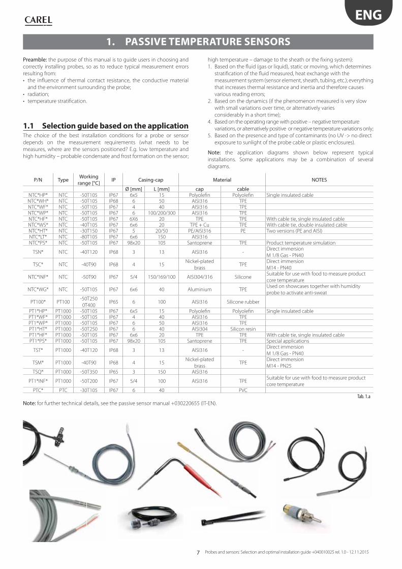
Preamble: the purpose of this manual is to guide users in choosing and
correctly installing probes, so as to reduce typical measurement errors
resulting from:
• the infl uence of thermal contact resistance, the conductive material
and the environment surrounding the probe;
• radiation;
• temperature stratifi cation.
1.1 Selection guide based on the application The choice of the best installation conditions for a probe or sensor
depends on the measurement requirements (what needs to be
measures, where are the sensors positioned? E.g. low temperature and
high humidity – probable condensate and frost formation on the sensor;
high temperature – damage to the sheath or the fi xing system):
1. Based on the fl uid (gas or liquid), static or moving, which determines
stratifi cation of the fl uid measured, heat exchange with the
measurement system (sensor element, sheath, tubing, etc.); everything
that increases thermal resistance and inertia and therefore causes
various reading errors;
2. Based on the dynamics (if the phenomenon measured is very slow
with small variations over time, or alternatively varies
considerably in a short time);
4. Based on the operating range with positive – negative temperature
variations, or alternatively positive or negative temperature variations only;
5. Based on the presence and type of contaminants (no UV -> no direct
exposure to sunlight of the probe cable or plastic enclosures).
Note: the application diagrams shown below represent typical
installations. Some applications may be a combination of several
diagrams.
P/N Type Working range [°C] IP Casing-cap Material NOTES
Ø [mm] L [mm] cap cableNTC*HP* NTC -50T105 IP67 6x5 15 Polyolefi n Polyolefi n Single insulated cableNTC*WH* NTC -50T105 IP68 6 50 AISI316 TPENTC*WF* NTC -50T105 IP67 4 40 AISI316 TPENTC*WP* NTC -50T105 IP67 6 100/200/300 AISI316 TPENTC*HF* NTC -50T105 IP67 6X6 20 TPE TPE With cable tie, single insulated cableNTC*WS* NTC -40T105 IP67 6x6 20 TPE + Cu TPE With cable tie, double insulated cableNTC*HT* NTC -30T150 IP67 5 20/50 PE/AISI316 PE Two versions (PE and AISI)NTC*LT* NTC -80T105 IP67 6x6 150 AISI316NTC*PS* NTC -50T105 IP67 98x20 105 Santoprene TPE Product temperature simulation
TSN* NTC -40T120 IP68 3 13 AISI316 -Direct immersion
M 1/8 Gas - PN40
TSC* NTC -40T90 IP68 4 15Nickel-plated
brassTPE
Direct immersion
M14 - PN40
NTC*INF* NTC -50T90 IP67 5/4 150/169/100 AISI304/316 SiliconeSuitable for use with food to measure product
core temperature
NTC*WG* NTC -50T105 IP67 6x6 40 Aluminium TPEUsed on showcases together with humidity
probe to activate anti-sweat
PT100* PT100-50T250
0T400IP65 6 100 AISI316 Silicone rubber
PT1*HP* PT1000 -50T105 IP67 6x5 15 Polyolefi n Polyolefi n Single insulated cablePT1*WF* PT1000 -50T105 IP67 4 40 AISI316 TPEPT1*WP* PT1000 -50T105 IP67 6 50 AISI316 TPEPT1*HT* PT1000 -50T250 IP67 6 40 AISI304 Silicon resinPT1*HF* PT1000 -50T105 IP67 6x6 20 TPE TPE With cable tie, single insulated cablePT1*PS* PT1000 -50T105 IP67 98x20 105 Santoprene TPE Special applications
TST* PT1000 -40T120 IP68 3 13 AISI316 -Direct immersion
M 1/8 Gas - PN40
TSM* PT1000 -40T90 IP68 4 15Nickel-plated
brassTPE
Direct immersion
M14 - PN25TSQ* PT1000 -50T350 IP65 3 150 AISI316
PT1*INF* PT1000 -50T200 IP67 5/4 100 AISI316 TPESuitable for use with food to measure product
core temperaturePTC* PTC -30T105 IP67 6 40 PVC
Tab. 1.a
Note: for further technical details, see the passive sensor manual +030220655 (IT-EN).
8
T
Ta
Di
ξ
Treal
Tmeas
Ae 4De=Vi DDi ∏/42
∏
ENG
Probes and sensors: Selection and optimal installation guide +040010025 rel. 1.0 - 12.11.2015
2. OBSERVATIONS ON HEAT TRANSMISSION
IN TEMPERATURE MEASUREMENTS
3. ACTIVE TEMPERATURE AND HUMIDITY SENSORS
Type of output
Temperature Humidity Carel NTC Carel NTC & -0.5-1 V / 4-20 mA
-0.5-1 V 4-20 mA
Carel NTC & 0-10 V 0-10 V RS485 serial
Duct-10 T60°C - DPDT011000 - DPDT010000 - - DPDT014000-10 T60°C 10-90% - DPDC111000 DPDC110000 - DPDC112000 DPDC114000
-20-70°C 0-100% - - DPDC210000 - DPDC212000 DPDC214000
Industrial environment
-10 T60°C - DPPT011000 - DPPT010000 - - DPPT014000-10 T60°C 10-90% - DPPC111000 DPPC110000 - DPPC112000 DPPC114000-20-70°C 0-100% - - DPPC210000 - DPPC212000 DPPC214000
Wall-mounting
-10 T60°C - DPWT011000 - DPWT010000 - - DPWT014000
-10 T60°C 10-90% - DPWC111000 DPWC110000 DPWC115000 DPWC112000 DPWC114000
Immersion - 30-90°C - - ASIT030000 - - -
Remote sensor
- 30-90°C Cable L= 2m - - ASET030000 - - -30-90°C Cable L= 3m - - ASET030001 - - -30-90°C Cable L= 4m - - ASET030002 - - -
Tab. 3.a
Note: for further technical details, see the active sensor manual +030220660 (IT-EN)
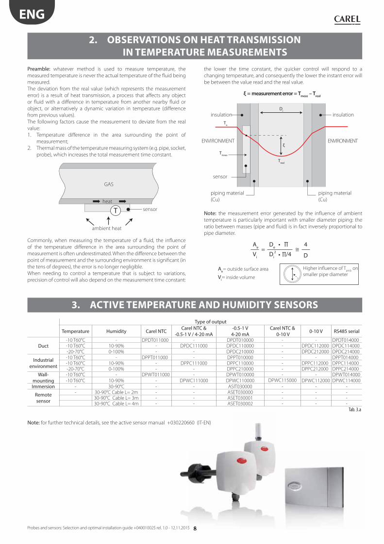
Preamble: whatever method is used to measure temperature, the
measured temperature is never the actual temperature of the fl uid being
measured.
The deviation from the real value (which represents the measurement
error) is a result of heat transmission, a process that aff ects any object
or fl uid with a diff erence in temperature from another nearby fl uid or
object, or alternatively a dynamic variation in temperature (diff erence
from previous values).
The following factors cause the measurement to deviate from the real
value:
1. Temperature diff erence in the area surrounding the point of
measurement;
2. Thermal mass of the temperature measuring system (e.g. pipe, socket,
probe), which increases the total measurement time constant.
Commonly, when measuring the temperature of a fl uid, the infl uence
of the temperature diff erence in the area surrounding the point of
measurement is often underestimated. When the diff erence between the
point of measurement and the surrounding environment is signifi cant (in
the tens of degrees), the error is no longer negligible.
When needing to control a temperature that is subject to variations,
precision of control will also depend on the measurement time constant:
the lower the time constant, the quicker control will respond to a
changing temperature, and consequently the lower the instant error will
be between the value read and the real value.
Note: the measurement error generated by the infl uence of ambient
temperature is particularly important with smaller diameter piping: the
ratio between masses (pipe and fl uid) is in fact inversely proportional to
pipe diameter.
ξ = measurement error = Tmeas
– Treal
Higher infl uence of Tamb
on
smaller pipe diameterVi= inside volume
Ae= outside surface area
heat
GAS
sensor
insulation
sensor
piping material
(Cu)
piping material
(Cu)
insulation
ENVIRONMENT ENVIRONMENT
ambient heat
9
ENG
Probes and sensors: Selection and optimal installation guide +040010025 rel. 1.0 - 12.11.2015
Carel DP*Q* P/NsVersion Outputs Carel part number
VOC air quality sensor, wall-mounting 0 to 10V – 4 to 20 mA DPWQ306000CO2 air quality sensor, wall-mounting 0 to 10V DPWQ402000VOC + CO2 air quality sensor, wall-mounting 0 to 10V DPWQ502000VOC air quality sensor, duct version 0 to 10V – 4 to 20 mA DPDQ306000CO2 air quality sensor, duct version 0 to 10V DPDQ402000VOC + CO2 air quality sensor, duct version 0 to 10V DPDQ502000
Tab. 4.a
Note: for further technical details see the air quality sensor technical leafl ets:
VOC VOC + CO2
+050001290 - IT +050001300 - IT
+050001291 - GB +050001301 - GB
+050001292 - FR +050001302 - FR
+050001293 - DE +050001303 - DE
+050001294 - RU +050001304 - RU
4. ACTIVE AIR QUALITY SENSORS
Semiconductor (IP41) Semiconductor with 5 m remote sensor (IP66) Description
DPWLA07000 DPWLA27000 R22 gas leak detectorDPWLB07000 DPWLB27000 R134a gas leak detectorDPWLC07000 DPWLC27000 R404a gas leak detectorDPWLR07000 R407a gas leak detectorDPWLD07000 DPWLD27000 R407c gas leak detectorDPWLS07000 R407f gas leak detectorDPWLE07000 DPWLE27000 R410a gas leak detectorDPWLT07000 DPWLT27000 R507a gas leak detector DPWLG07000 NH3 gas leak detectorDPWLQ07000 ETHYLENE gas leak detector DPWLP07000 R290 gas leak detector
Infrared (IP66) Infrared with 5 m remote sensor (IP66) Description
DPWL417000 DPWL427000 Sensor rilevam. gas CO2
Tab. 5.a
Note: for further technical details, see the specifi c manual: +0300035EN or +0300035IT
5. REFRIGERANT GAS LEAKAGE SENSORS
(R22, R134A, R290, R404A, R407C-F, R410A, R744, ETHYLENE)
10
ENG
Probes and sensors: Selection and optimal installation guide +040010025 rel. 1.0 - 12.11.2015
6. PRESSURE SENSORS
See the specifi c technical leafl ets:
4-20 mA active sensors +050000651 (IT-EN) On-off sensors +050000645 (IT-EN)
P/N Working range (adjustable) Output
SPKD00U5N0
0 - 1000 Pa
0 - 2500 Pa
0 - 3000 Pa
0 - 5000 Pa
4 - 20 mA
SPKD00C5N0
– 50 - + 50 Pa
– 100 - + 100 Pa
0 - + 50 Pa
0 - + 100 Pa
4 - 20 mA
Tab. 7.a
P/N DescriptionRange (mbar)
DCPD000100 Diff erential pressure switch 0.5 - 5.0
DCPD010100 Diff erential pressure switch 0.5 - 5.0with
connection kitDCPD001100 Diff erential pressure switch 0.2 - 2.0
DCPD011100 Diff erential pressure switch 0.2 - 2.0with
connection kitTab. 7.b
Choice of pressure sensor according to operating pressure.
Gas Low temperature evaporator Medium and high temperature evaporator Condenser R134a SPKT0053R*/P* (0-5 V; -1.0-4.2 barg)
SPKT0021C*/D* (4-20 mA; -0.5-7.0 barg)
SPKS0019R1 (0-5 V; 0-9 barg) weld version
SPKT0013R*/P* (0-5 V; -1-9.3 barg)
SPKT0011C*/D* (4-20 mA; 0-10 barg)
SPKS0019R1 (0-5 V; 0-9 barg) weld version
SPKT0033R*/P* (0-5 V; 0-34.5 barg)
SPKT0031C*/D* (4-20 mA; 0-30 barg)
SPKS0039R1 (0-5 V; 0-34 barg) weld version
R290 SPKT0013R*/P* (0-5 V; -1-9.3 barg)
SPKT0011C*/D* (4-20 mA; 0-10 barg)
SPKS0019R1 (0-5 V; 0-9 barg) weld version
SPKT0013R*/P* (0-5 V; -1-9.3 barg)
SPKT0011C*/D* (4-20 mA; 0-10 barg)
SPKS0019R1 (0-5 V; 0-9 barg) weld version
SPKT0033R*/P* (0-5 V; 0-34.5 barg)
SPKT0031C*/D* (4-20 mA; 0-30 barg)
SPKS0039R1 (0-5 V; 0-34 barg) weld versionR404a SPKT0013R*/P* (0-5 V; -1-9.3 barg)
SPKT0011C*/D* (4-20 mA; 0-10 barg)
SPKS0019R1 (0-5 V; 0-9 barg) weld version
SPKT0013R*/P* (0-5 V; -1-9.3 barg)
SPKT0011C*/D* (4-20 mA; 0-10 barg)
SPKS0019R1 (0-5 V; 0-9 barg) weld version
SPKT0033R*/P* (0-5 V; 0-34.5 barg)
SPKT0031C*/D* (4-20 mA; 0-30 barg)
SPKS0039R1 (0-5 V; 0-34 barg) weld version
R407A SPKT0013R*/P* (0-5 V; -1-9.3 barg)
SPKT0011C*/D* (4-20 mA; 0-10 barg)
SPKS0019R1 (0-5 V; 0-9 barg) weld version
SPKT0013R*/P* (0-5 V; -1-9.3 barg)(1)
SPKT0011C*/D* (4-20 mA; 0-10 barg)(1)
SPKS0019R1 (0-5 V; 0-9 barg) weld version
SPKT0033R*/P* (0-5 V; 0-34.5 barg)
SPKT0031C*/D* (4-20 mA; 0-30 barg)
SPKS0039R1 (0-5 V; 0-34 barg) weld version
R407C SPKT0013R*/P* (0-5 V; -1-9.3 barg)
SPKT0011C*/D* (4-20 mA; 0-10 barg)
SPKS0019R1 (0-5 V; 0-9 barg) weld version
SPKT0013R*/P* (0-5 V; -1-9.3 barg)(1)
SPKT0011C*/D* (4-20 mA; 0-10 barg)(1)
SPKS0019R1 (0-5 V; 0-9 barg) weld version
SPKT0033R*/P* (0-5 V; 0-34.5 barg)
SPKT0031C*/D* (4-20 mA; 0-30 barg)
SPKS0039R1 (0-5 V; 0-34 barg) weld version
R407F SPKT0013R*/P* (0-5 V; -1-9.3 barg)
SPKT0011C*/D* (4-20 mA; 0-10 barg)
SPKS0019R1 (0-5 V; 0-9 barg) weld version
SPKT0013R*/P* (0-5 V; -1-9.3 barg)(1)
SPKT0011C*/D* (4-20 mA; 0-10 barg)(1)
SPKS0019R1 (0-5 V; 0-9 barg) weld version
SPKT0033R*/P* (0-5 V; 0-34.5 barg)
SPKT0031C*/D* (4-20 mA; 0-30 barg)
SPKS0039R1 (0-5 V; 0-34 barg) weld version
R410A SPKT0043R*/P* (0-5 V; 0-17.3 barg)
SPKT0041C*/D* (4-20 mA; 0-18.2 barg)
SPKS00F9R1 (0-5 V; 0-19 barg) weld version
SPKT0043R*/P* (0-5 V; 0-17.3 barg)
SPKT0041C*/D* (4-20 mA; 0-18.2 barg)
SPKS00F9R1 (0-5 V; 0-19 barg) weld version
SPKT00B6R*/P* (0-5 V; 0-45 barg)
SPKT00B1C*/D* (4-20 mA; 0-44.8 barg)
SPKS00B9R1 (0-5 V; 0-45 barg) weld version
R717 SPKT0021C*/D* (4-20 mA; -0.5..7 barg) SPKT0011C*/D* (4-20 mA; 0-10 barg) SPKT0031C*/D* (4-20 mA; 0-30 barg)R744 SPKT00G1C*/D* (4-20 mA; 0-60 barg) SPKT00G1C*/D* (4-20 mA; 0-60 barg) SPKT00H8C* (4-20 mA; 0-120 barg)
SPKT00D8C* (4-20 mA; 0-150 barg)
Tab. 6.a (1): for HVAC applications, use respectively
• SPKT0043R*/P* (0-5 V 0-17.3 barg)
• SPKT0041C*/D* (4-20 mA 0-18.2 barg)
• SPKS00F9R1 (0-5 V 0-19 barg) weld version
Specifi c documents: for further technical details see the pressure
transducer technical leafl ets:
• cable and connector +050000484
• 4-20 mA C series +050000486 (IT-EN) alternative: 4-20 mA D series +050000595 (IT-EN)
• 4-20 mA C series high pressure +050000596 (IT-EN)
• 0-5 V R series +050000485 (IT-EN) alternative: 0-5 V P series +050000598 (IT-EN)
• 0-5 V S series +050000488 (IT-EN)
• 0-5 V SPKS* series weld version +050000489 (IT-EN)
Note: the SPKS*R* series weld-version sensors comply with F-GAS
regulation 842/2006, which requires devices installed in the system
to be hermetically sealed and solidly secured by welding.
7. DIFFERENTIAL PRESSURE SENSORS

11
ENG
Probes and sensors: Selection and optimal installation guide +040010025 rel. 1.0 - 12.11.2015
8. FLOOD SENSORS
9. FROST SENSORS
10. SMOKE-FIRE SENSORS
11. LEVEL SENSORS
Technical leafl et +050004116
Technical leafl et +050000646
Technical leafl et +050000520
Technical leafl et +0500075ML
P/N DescriptionFLOE000010 Flood detectorFLOS000000 Spot probeFLOR000000 Strip sensor 25 m
Tab. 8.a
P/N Description Range (°C)DCTF000320 Single-stage frost thermostat -10 to 15
Tab. 9.a
SmokeP/N Power supply voltage
SFFS000000 12-24 VdcTab. 10.a
FireP/N Power supply voltage
SFFF000000 12-24 VdcTab. 10.b
P/N DescriptionLSR0013000 Level sensor – 2” Gas mechanical connectorLSR0023000 Level sensor – fl anged mechanical connector
Tab. 11.a
Smoke sensor
Strip sensor
Spot probeFlood detector
2" Gas
Fiire sensor
with fl ange

12
ΔP
– +
– +
T rH%
T
T
T
rH%
ΔP
T
ENG
Probes and sensors: Selection and optimal installation guide +040010025 rel. 1.0 - 12.11.2015
KEY
T Temperature
rH% Relative humidity
ΔP Diff erential pressure
CO2 CO2
VOC Volatile organic compounds
Diff erential air
pressure sensor
DCPD0* or SPKD*
Sintered
polymer
silencer
or
Outside probe
DPUC* (T/H)
Outside probe
DPP* (T/H)
Thermal insulation
Duct probe DPD*
(T/H)
Immersion probe TSN
Socket
12. INSTALLATION DIAGRAMS BY APPLICATION
12.1 AHU
MAX
40 Bar

13
ΔP
ΔP ΔP
VOCCO2
VOCCO2
– +
–+
+ –
T rH%
T rH%
rH%
T rH%
T
ENG
Probes and sensors: Selection and optimal installation guide +040010025 rel. 1.0 - 12.11.2015
NTC*WF*
Socket with
thermal grease
wind cable at least
three times
Thermal insulation
Alternative solutions
Duct probe DPD* (T/H)
Duct air
quality
Room air
quality
DPWQ*
Room probe
DPW* (T/H)
14
T
T
T
T T P
T
T
T
X = 10 D
D
ENG
Probes and sensors: Selection and optimal installation guide +040010025 rel. 1.0 - 12.11.2015
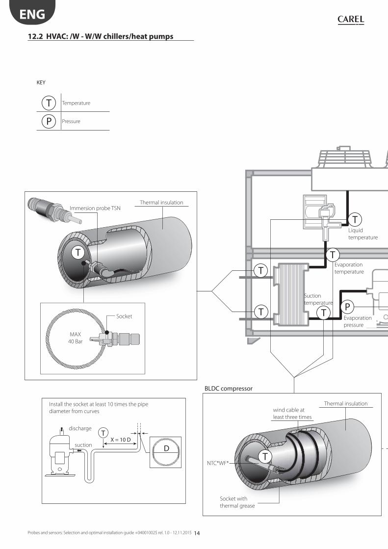
12.2 HVAC: /W - W/W chillers/heat pumps
KEY
T Temperature
P Pressure
Liquid
temperature
NTC*WF*
suction
discharge
wind cable at
least three times
Thermal insulation
BLDC compressor
Evaporation
temperature
Suction
temperature
Socket with
thermal grease
Socket
Thermal insulationImmersion probe TSN
MAX
40 Bar
Install the socket at least 10 times the pipe
diameter from curves
Evaporation
pressure
15
T
T
P
P
T
T
P
P
T
T
Ø ≤ 16 mm T Ø > 16 mm
ENG
Probes and sensors: Selection and optimal installation guide +040010025 rel. 1.0 - 12.11.2015
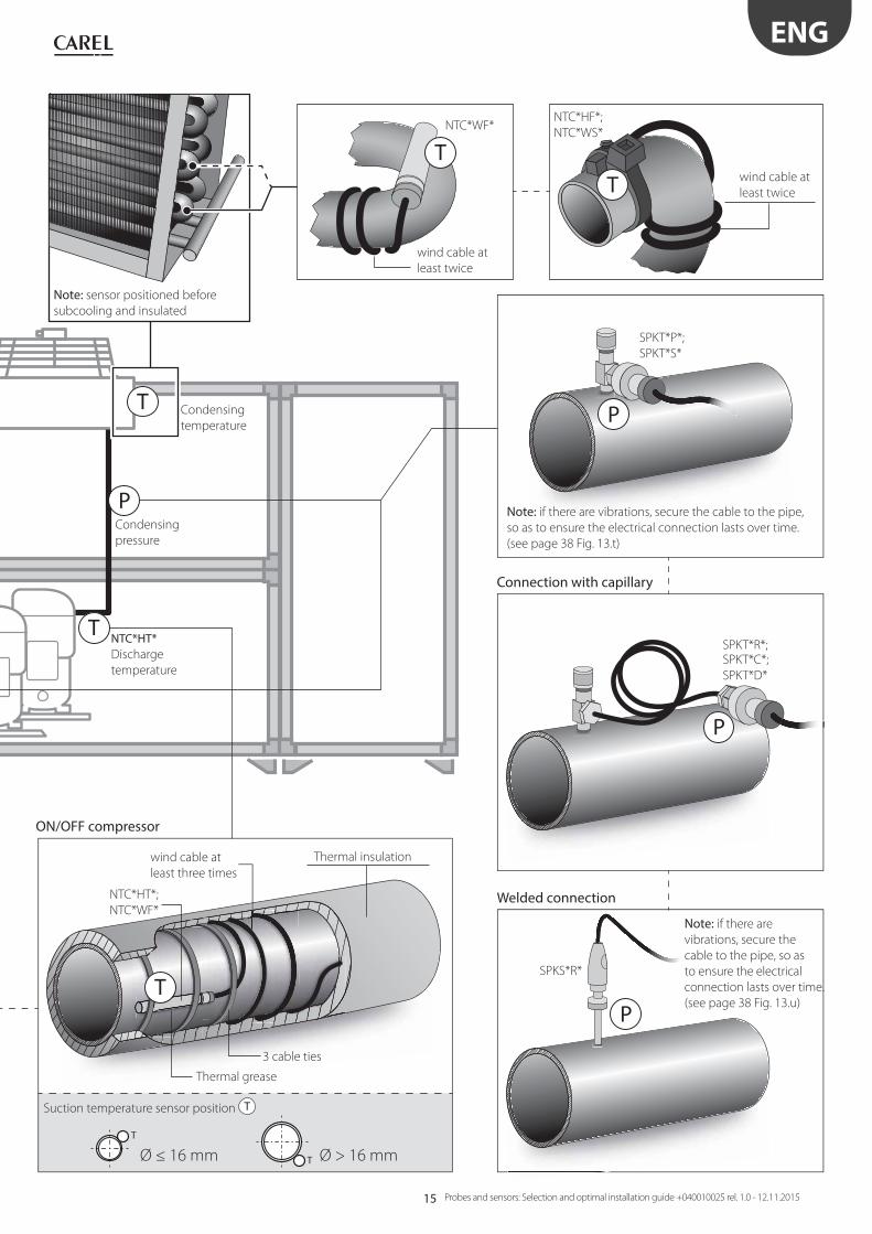
Condensing
temperature
Condensing
pressure
NTC*HT*Discharge
temperature
Thermal insulation
Suction temperature sensor position T
SPKT*P*;
SPKT*S*
SPKT*R*;SPKT*C*;
SPKT*D*
SPKS*R*
NTC*HF*;
NTC*WS* NTC*WF*
wind cable at
least twice
Note: sensor positioned before
subcooling and insulated
Note: if there are
vibrations, secure the
cable to the pipe, so as
to ensure the electrical
connection lasts over time.
(see page 38 Fig. 13.u)
Note: if there are vibrations, secure the cable to the pipe,
so as to ensure the electrical connection lasts over time.
(see page 38 Fig. 13.t)
ON/OFF compressor
Connection with capillary
Thermal grease
3 cable ties
Welded connection
wind cable at
least three times
NTC*HT*;
NTC*WF*
wind cable at
least twice

16
T rH%
ΔP –
–
+
+ΔP
T
TX = 10 D
D
T
P
ENG
Probes and sensors: Selection and optimal installation guide +040010025 rel. 1.0 - 12.11.2015
12.3 CRAC
KEY
T Temperature
P Pressure
rH% Relative humidity
ΔP Diff erential pressure
S Smoke
F Fire
L Flood sensor
NTC*WF*
wind cable at
least three times
Thermal insulation
Sintered
polymer
silencer
Optional probe
DPP* (T/H)
NTC*HP*
BLDC compressor
Socket with
thermal grease
Diff erential air
pressure sensor
DCPD0* or SPKD*
suction
discharge
Install the socket at least 10 times the pipe
diameter from curves
NTC*HT*
17
T rH%
S F
T
T
Ø ≤ 16 mm T Ø > 16 mm
TP
L
P
P
P
ENG
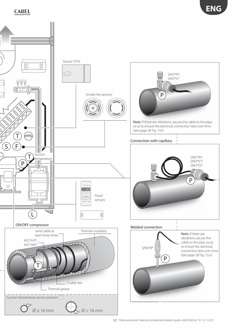
Probes and sensors: Selection and optimal installation guide +040010025 rel. 1.0 - 12.11.2015
wind cable at
least three times
Sensor (T/H)
Smoke-fi re sensors
Thermal insulation
NTC*HT*;
NTC*WF*
ON/OFF compressor
Thermal grease
Connection with capillary
Welded connection
3 cable ties
SPKT*R*;SPKT*C*;
SPKT*D*
SPKS*R*
Suction temperature sensor position T
Flood
sensors
SPKT*P*;
SPKT*S*
Note: if there are
vibrations, secure the
cable to the pipe, so as
to ensure the electrical
connection lasts over time.
(see page 38 Fig. 13.u)
Note: if there are vibrations, secure the cable to the pipe,
so as to ensure the electrical connection lasts over time.
(see page 38 Fig. 13.t)
Suction
temperature
18
T rH%
S
ΔP –
–
+
+ΔP
T
T
ENG
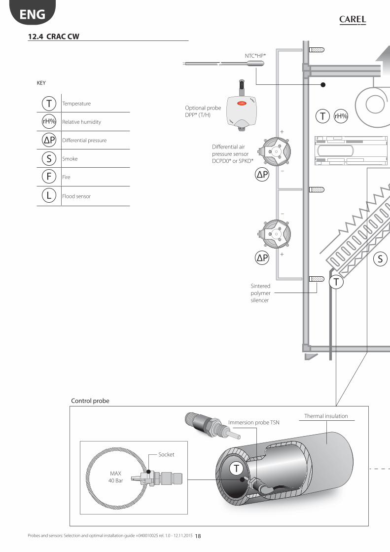
Probes and sensors: Selection and optimal installation guide +040010025 rel. 1.0 - 12.11.2015
12.4 CRAC CW
KEY
T Temperature
rH% Relative humidity
ΔP Diff erential pressure
S Smoke
F Fire
L Flood sensor
Sintered
polymer
silencer
Optional probe
DPP* (T/H)
NTC*HP*
Thermal insulationImmersion probe TSN
Socket
Control probe
MAX
40 Bar
Diff erential air
pressure sensor
DCPD0* or SPKD*
19
T rH%
L
F
T
T
T
ENG
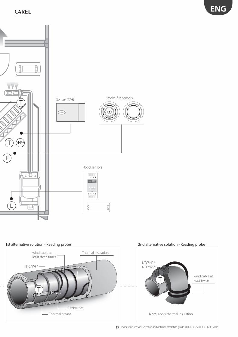
Probes and sensors: Selection and optimal installation guide +040010025 rel. 1.0 - 12.11.2015
wind cable at
least three times
Thermal insulation
Note: apply thermal insulation
NTC*WF*
Sensor (T/H)
Flood sensors
Smoke-fi re sensors
Thermal grease
1st alternative solution - Reading probe 2nd alternative solution - Reading probe
3 cable ties
NTC*HF*;
NTC*WS*
wind cable at
least twice
20
T
TT
T
T T
P
T
ENG
Probes and sensors: Selection and optimal installation guide +040010025 rel. 1.0 - 12.11.2015
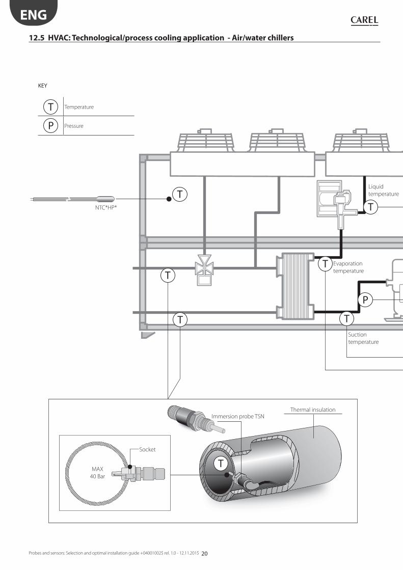
12.5 HVAC: Technological/process cooling application - Air/water chillers
KEY
T Temperature
P Pressure
Suction
temperature
Liquid
temperature
Evaporation
temperature
Thermal insulationImmersion probe TSN
Socket
MAX
40 Bar
NTC*HP*
21
T
P
T
P
P
P
T
ENG
Probes and sensors: Selection and optimal installation guide +040010025 rel. 1.0 - 12.11.2015
NTC*WF*wind cable at
least three times
Thermal insulation
Discharge
temp.
Socket with
thermal grease
Connection with capillary
Welded connection
SPKT*R*;SPKT*C*;
SPKT*D*
SPKS*R*
SPKT*P*;
SPKT*S*
Note: if there are
vibrations, secure the
cable to the pipe, so as
to ensure the electrical
connection lasts over time.
(see page 38 Fig. 13.u)
Note: if there are vibrations, secure the cable to the pipe,
so as to ensure the electrical connection lasts over time.
(see page 38 Fig. 13.t)
wind cable at
least three times
Thermal insulation
NTC*HT*
Thermal grease
3 cable ties
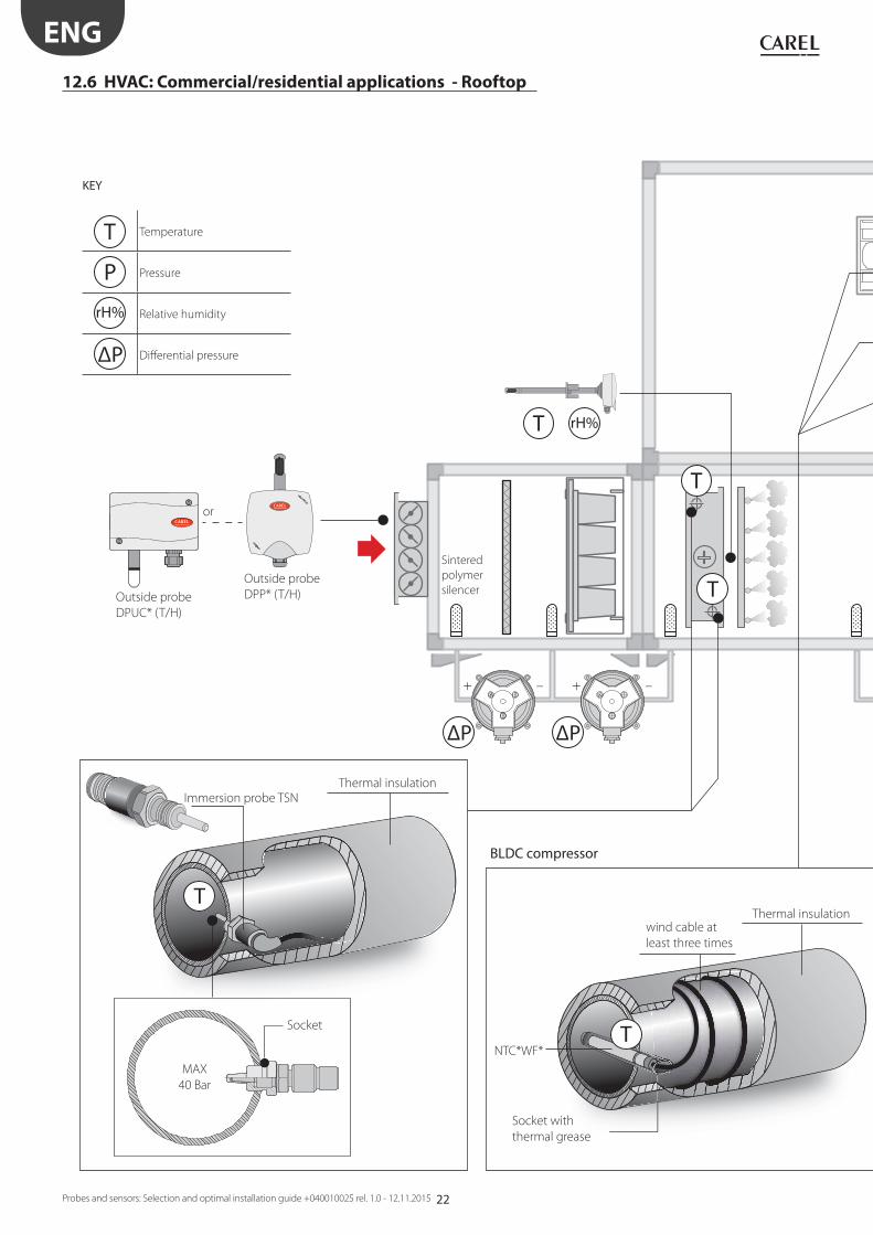
22
ΔP
–+
ΔP
–+
T
T rH%
T
T
T
ENG
Probes and sensors: Selection and optimal installation guide +040010025 rel. 1.0 - 12.11.2015
12.6 HVAC: Commercial/residential applications - Rooftop
KEY
T Temperature
P Pressure
rH% Relative humidity
ΔP Diff erential pressure
wind cable at
least three times
Thermal insulation
BLDC compressor
Sintered
polymer
silencer
or
Outside probe
DPP* (T/H)Outside probe
DPUC* (T/H)
Socket with
thermal grease
Socket
Thermal insulation
Immersion probe TSN
MAX
40 Bar
NTC*WF*
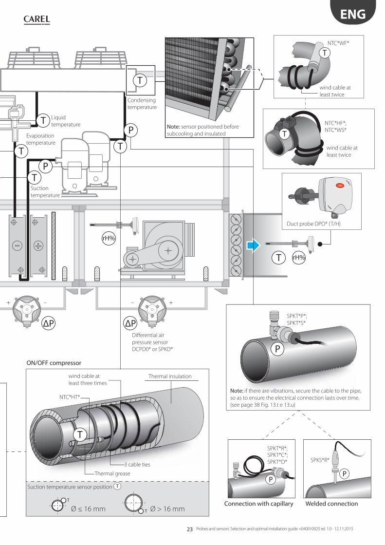
23
ΔP ΔP
– +–+
rH%
T rH%
T
T
TP
P
T
PP
T
T
Ø ≤ 16 mm T Ø > 16 mm
T
T
T
P
ENG
Probes and sensors: Selection and optimal installation guide +040010025 rel. 1.0 - 12.11.2015
Evaporation
temperature
Suction
temperature
wind cable at
least three times
Thermal insulation
NTC*HT*
ON/OFF compressor
Duct probe DPD* (T/H)
Liquid
temperature
Thermal grease
Connection with capillary Welded connection
3 cable ties
SPKT*R*;SPKT*C*;
SPKT*D* SPKS*R*
Diff erential air
pressure sensor
DCPD0* or SPKD*
Suction temperature sensor position T
SPKT*P*;
SPKT*S*
Note: if there are vibrations, secure the cable to the pipe,
so as to ensure the electrical connection lasts over time.
(see page 38 Fig. 13.t e 13.u)
NTC*HF*;
NTC*WS*
NTC*WF*
wind cable at
least twice
wind cable at
least twice
Note: sensor positioned before
subcooling and insulated
Condensing
temperature
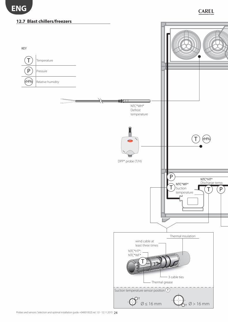
24
T rH%
P
P
TT
T
T
Ø ≤ 16 mm T Ø > 16 mm
ENG
Probes and sensors: Selection and optimal installation guide +040010025 rel. 1.0 - 12.11.2015
12.7 Blast chillers/freezers
NTC*WH*
Defrost
temperature
wind cable at
least three times
Thermal insulation
KEY
T Temperature
P Pressure
rH% Relative humidity
Thermal grease
3 cable ties
NTC*WF* Suction
temperature
NTC*HT* Discharge temp.
DPP* probe (T/H)
Suction temperature sensor position T
NTC*HT*;
NTC*WF*
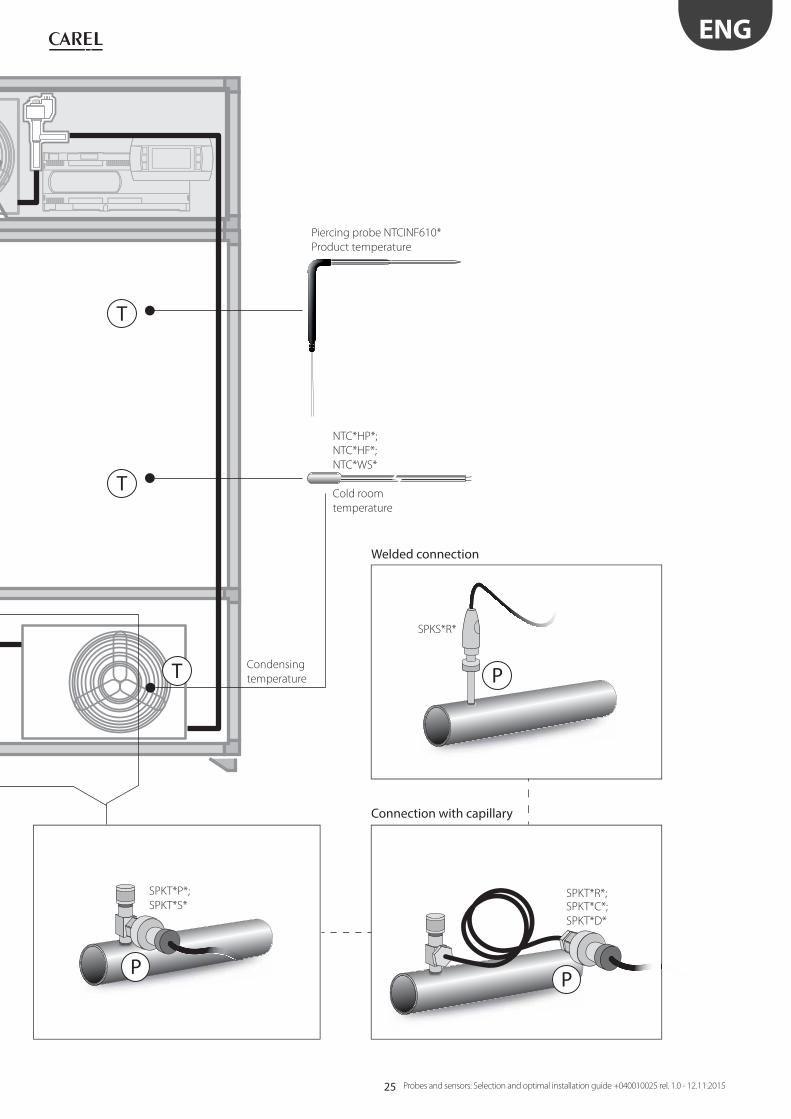
25
T
T
T P
P P
ENG
Probes and sensors: Selection and optimal installation guide +040010025 rel. 1.0 - 12.11.2015
NTC*HP*;
NTC*HF*;
NTC*WS*
Cold room
temperature
Piercing probe NTCINF610*
Product temperature
Condensing
temperature
Connection with capillary
Welded connection
SPKT*R*;SPKT*C*;
SPKT*D*
SPKS*R*
SPKT*P*;
SPKT*S*
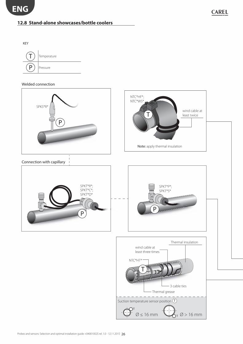
26
T
P
P
T
Ø ≤ 16 mm T Ø > 16 mm
P
T
ENG
Probes and sensors: Selection and optimal installation guide +040010025 rel. 1.0 - 12.11.2015
KEY
T Temperature
P Pressure
12.8 Stand-alone showcases/bottle coolers
wind cable at
least three times
Thermal insulation
Thermal grease
Connection with capillary
Welded connection
SPKT*R*;SPKT*C*;
SPKT*D*
SPKS*R*
3 cable ties
Suction temperature sensor position T
SPKT*P*;
SPKT*S*
NTC*HT*
Note: apply thermal insulation
NTC*HF*;
NTC*WS*
wind cable at
least twice

27
T
T
T
T
T
P
T
T
ENG
Probes and sensors: Selection and optimal installation guide +040010025 rel. 1.0 - 12.11.2015
NTC*WH*
Defrost temperature
Note: install the sensor in the position of
maximum frost formation
NTC*HP*
Air
NTC*PS*
Product
simulation
temperature
Discharge
temperature
Suction
temperature
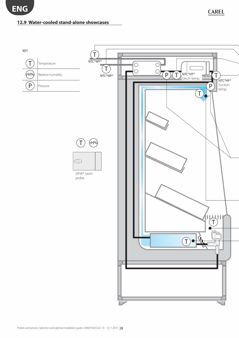
28
T
P
TT
T
TP
T rH%
T
T
ENG
Probes and sensors: Selection and optimal installation guide +040010025 rel. 1.0 - 12.11.2015
12.9 Water-cooled stand-alone showcases
KEY
T Temperature
rH% Relative humidity
P Pressure
NTC*HF*Suction
temp.
NTC*HT*Disch. temp.
NTC*WF*
NTC*WF*
DPW* room
probe
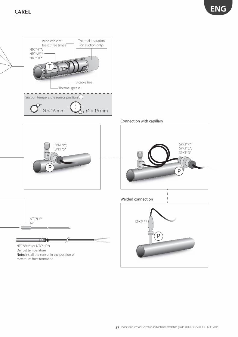
29
T
Ø ≤ 16 mm T Ø > 16 mm
T
P
PP
ENG
Probes and sensors: Selection and optimal installation guide +040010025 rel. 1.0 - 12.11.2015
NTC*WH* (or NTC*HP*)
Defrost temperature
Note: install the sensor in the position of
maximum frost formation
wind cable at
least three times
Thermal insulation
(on suction only)
NTC*HT*;
NTC*WF*;
NTC*HF*
NTC*HP*
Air
Thermal grease
Connection with capillary
Welded connection
SPKT*R*;SPKT*C*;
SPKT*D*
SPKS*R*
3 cable ties
Suction temperature sensor position T
SPKT*P*;
SPKT*S*

30
T
P
P
T
Ø ≤ 16 mm T Ø > 16 mm
P
ENG
Probes and sensors: Selection and optimal installation guide +040010025 rel. 1.0 - 12.11.2015
KEY
T Temperature
P Pressure
12.10 Centralised/multiplexed cabinets
wind cable at
least three times
Thermal insulation
NTC*HF*;
NTC*WS*;
NTC*HP*
Thermal grease
Connection with capillary
Welded connection
SPKT*R*;SPKT*C*;
SPKT*D*
SPKS*R*
3 cable ties
Evaporator outlet temperature sensor position T
SPKT*P*;
SPKT*S*
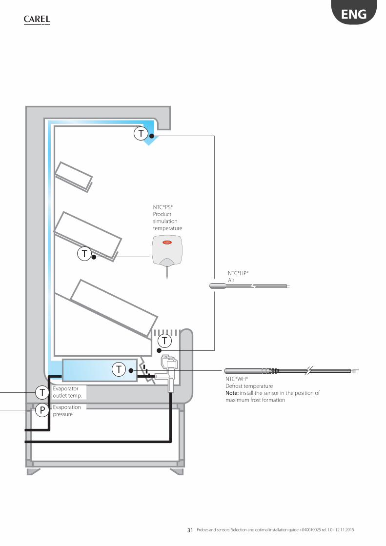
31
T
P
T
T
T
T
ENG
Probes and sensors: Selection and optimal installation guide +040010025 rel. 1.0 - 12.11.2015
NTC*HP*
Air
NTC*PS*
Product
simulation
temperature
Evaporation
pressure
Evaporator
outlet temp.
NTC*WH*
Defrost temperature
Note: install the sensor in the position of
maximum frost formation
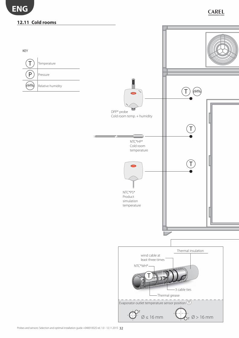
32
T
T
T
rH%
T
T
Ø ≤ 16 mm T Ø > 16 mm
ENG
Probes and sensors: Selection and optimal installation guide +040010025 rel. 1.0 - 12.11.2015
12.11 Cold rooms
NTC*PS*
Product
simulation
temperature
NTC*HP*
Cold room
temperature
DPP* probe
Cold room temp. + humidity
wind cable at
least three times
Thermal insulation
NTC*WH*
KEY
T Temperature
P Pressure
rH% Relative humidity
Thermal grease
3 cable ties
Evaporator outlet temperature sensor position T

33
PT
N L
18 1
9 20
13 1
4 15
10
11
127
8
91
2
16 1
75
63
4
T
P
P
P
ENG
Probes and sensors: Selection and optimal installation guide +040010025 rel. 1.0 - 12.11.2015
evaporator probe
Connection with capillaryWelded connection
SPKT*R*;SPKT*C*;
SPKT*D*
SPKS*R*
SPKT*P*;
SPKT*S*
NTC*WH*
Defrost temperature
Note: install the sensor in the position of
maximum frost formation
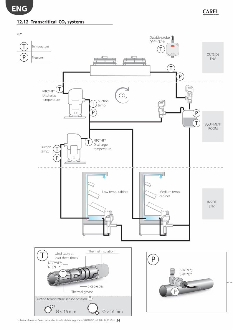
34
P
T
P
T
PT
T
P
T
T
T
CO2
T
T
Ø ≤ 16 mm T Ø > 16 mm
P
T P
ENG
Probes and sensors: Selection and optimal installation guide +040010025 rel. 1.0 - 12.11.2015
12.12 Transcritical CO2 systems
Medium temp.
cabinet
Low temp. cabinet
KEY
T Temperature
P Pressure
wind cable at
least three times
Thermal insulation
Thermal grease
3 cable ties
Outside probe
DPP* (T/H)
Suction temperature sensor position T
Suction
temp.
OUTSIDE
ENV.
EQUIPMENT
ROOM
INSIDE
ENV.
Suction
temp.
NTC*HT*Discharge
temperature
NTC*HT*Discharge
temperature
NTC*WF*;
NTC*HT*SPKT*C*;
SPKT*D*
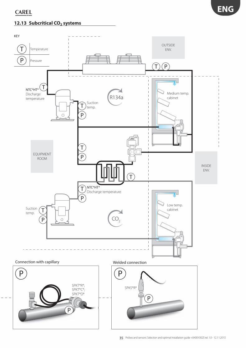
35
T
P
T
P
T
P
T
R134a
CO2
P
T
PT
T
P
P
P P
ENG
Probes and sensors: Selection and optimal installation guide +040010025 rel. 1.0 - 12.11.2015
12.13 Subcritical CO2 systems
Medium temp.
cabinet
Low temp.
cabinet
KEY
T Temperature
P Pressure
Connection with capillary
SPKT*R*;SPKT*C*;
SPKT*D*
Welded connection
SPKS*R*
INSIDE
ENV.
Suction
temp.
Suction
temp.
OUTSIDE
ENV.
EQUIPMENT
ROOM
NTC*HT*Discharge
temperature
NTC*HT*Discharge temperature

36
50 cm
150 cm
Fig. 13.a Fig. 13.b
Fig. 13.c Fig. 13.d
Fig. 13.e Fig. 13.f
Fig. 13.g
HIGH
Fig. 13.h
Fig. 13.i Fig. 13.l
ENG
Probes and sensors: Selection and optimal installation guide +040010025 rel. 1.0 - 12.11.2015
13. FURTHER SUGGESTIONS
13.1 Room temperature and humidity sensors
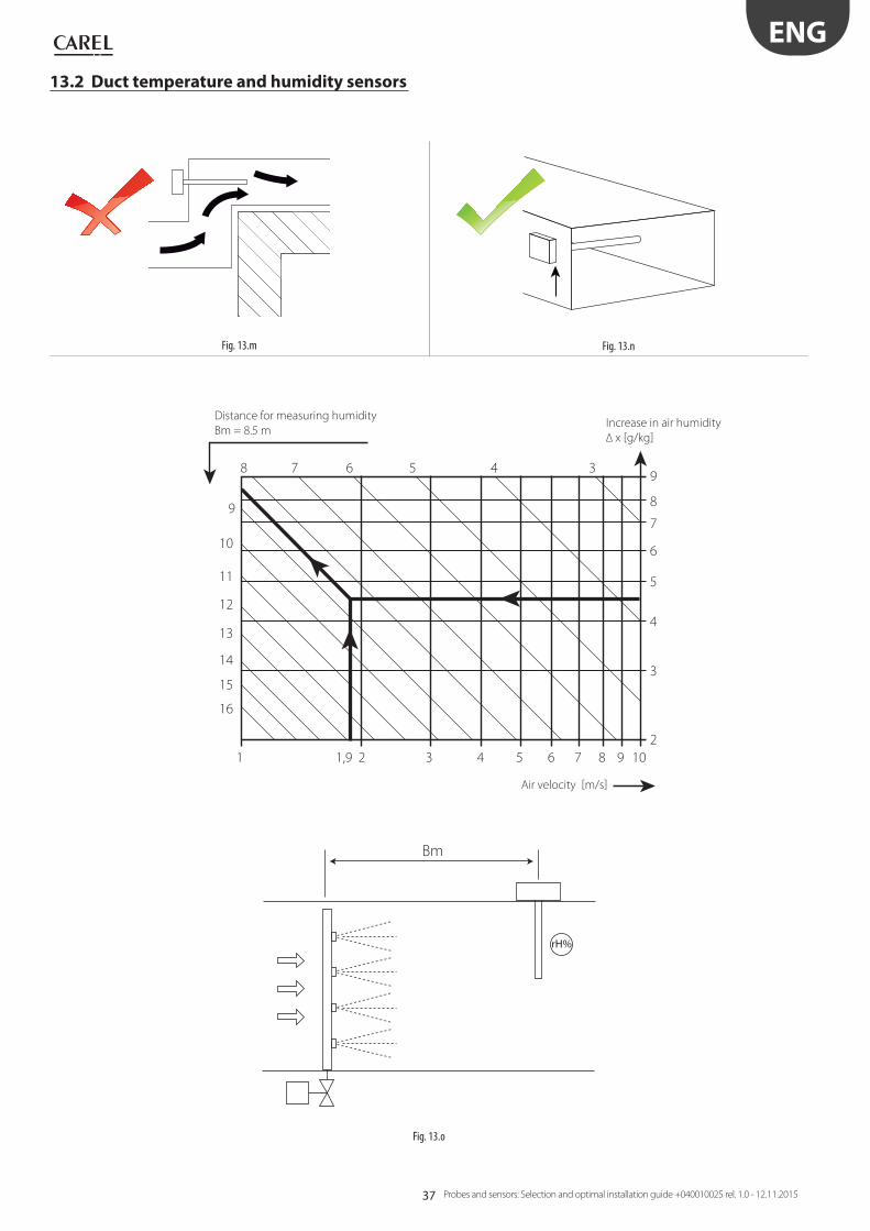
37
Bm
rH%
8
1 21,9 3 4 5 6 7 8 9 10
2
3
4
5
6
7
8
9
9
10
11
12
13
14
15
16
7 6 5 4 3
Fig. 13.m Fig. 13.n
Fig. 13.o
ENG
Probes and sensors: Selection and optimal installation guide +040010025 rel. 1.0 - 12.11.2015
Distance for measuring humidity
Bm = 8.5 m
Air velocity [m/s]
Increase in air humidity
Δ x [g/kg]
13.2 Duct temperature and humidity sensors
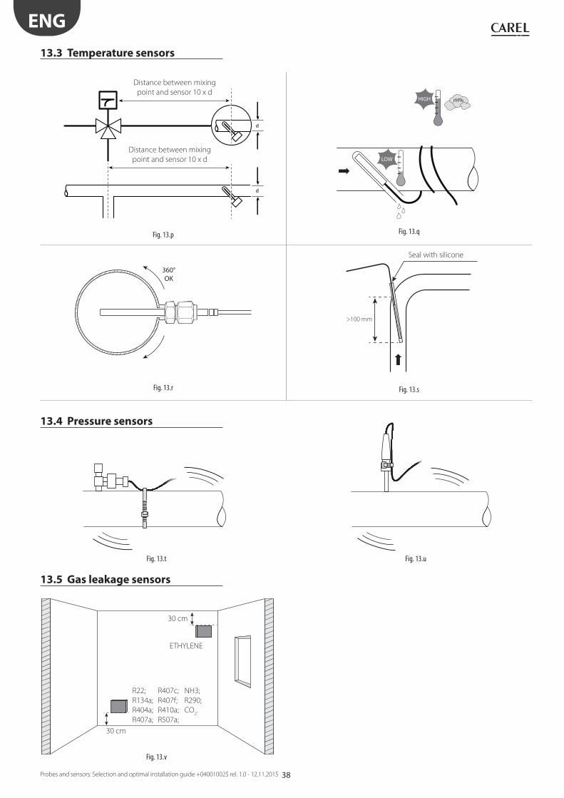
38
d
d
Fig. 13.p
HIGH
LOW
rH%
Fig. 13.q
360°OK
Fig. 13.r
>100 mm
Fig. 13.s
Fig. 13.v
Fig. 13.t Fig. 13.u
ENG
Probes and sensors: Selection and optimal installation guide +040010025 rel. 1.0 - 12.11.2015
Seal with silicone
Distance between mixing
point and sensor 10 x d
Distance between mixing
point and sensor 10 x d
13.3 Temperature sensors
13.4 Pressure sensors
13.5 Gas leakage sensors
30 cm
30 cm
R22; R407c; NH3;
R134a; R407f; R290;
R404a; R410a; CO2.
R407a; R507a;
ETHYLENE

39
ENG
Probes and sensors: Selection and optimal installation guide +040010025 rel. 1.0 - 12.11.2015

CAREL INDUSTRIES - HeadquartersVia dell’Industria, 11 - 35020 Brugine - Padova (Italy)
Tel. (+39) 049.9716611 - Fax (+39) 049.9716600
e-mail: [email protected] - www.carel.com
Agenzia / Agency:
So
nd
e e
se
nso
ri: G
uid
a al
la s
celt
a e
all'
inst
alla
zio
ne
ott
imal
e +
04
00
10
02
5 r
el.
1.0
- 1
2.1
1.2
01
5