SOFFIANTI, VENTILATORI COMPRESSORIe per BIOGAS e GAS ...
48
SOFFIANTI, VENTILATORI e COMPRESSORI per BIOGAS e GAS NATURALE, in conformità alla Direttiva 2014/34/UE (ATEX) BLOWERS, FANS and COMPRESSORS for BIOGAS, LANDFILL and NATURAL GAS, in conformity with 2014/34/EU Directive (ATEX) ®
Transcript of SOFFIANTI, VENTILATORI COMPRESSORIe per BIOGAS e GAS ...

SOFFIANTI, VENTILATORI e COMPRESSORIper BIOGAS e GAS NATURALE, in conformità alla Direttiva 2014/34/UE (ATEX)
BLOWERS, FANS and COMPRESSORSfor BIOGAS, LANDFILL and NATURAL GAS,in conformity with 2014/34/EU Directive (ATEX)
®

Mapro International SpA nasce nel 1959, con la denominazione sociale di M.P.R. Italiana SpA, come società costruttrice di compressori e pompe per vuoto rotative speciali, su commessa, per I’aspirazione e la compressione di fluidi gassosi. L’impiego di tali macchine nei più svariati settori industriali, dall'aIimentare al farmaceutico, dallo stampaggio alle macchine per il confezionamento, negli impianti di processo, nel disinquinamento ambientale, ecc., costituisce la base di una consolidata esperienza che consente, oggi, alla nostra società, di fornire soluzioni affidabili ed economiche per qualunque problema di convogliamento di aria o gas tecnici.
Conformità dei prodotti I Prodotti MAPRO® sono: • Conformi alle leggi e alle Norme Tecniche • Conformi alle richieste del Cliente• Idonei all’uso previsto• Sicuri e affidabili
Principali Direttive Europee applicabili:• 2006/42/CE Sicurezza delle Macchine• 2014/35/UE Bassa Tensione• 2014/30/UE Compatibilità Elettromagnetica• 2014/68/UE (PED) Attrezzature in pressione• 2014/34/UE (ATEX) Apparecchiature utilizzate in atmosfera
potenzialmente esplosiva
Mapro International SpA was established in 1959, under the company name of M.P.R. Italiana SpA, as manufacturer, on order, of special rotary compressors and vacuum pumps to compress and evacuate gaseous fluids.
Any problem of conveyance of air or industrial gases can be solved with reliable and economic solutions, thanks to a solid experience acquired through the manufacturing of machines for all industrial sectors, from food to
pharmaceutical industry, from textile to printing and paper industry, for all sort of
industrial process and for any biomass gas transfer.
Product ConformityMAPRO® Products are:
• In conformity with Laws and Technical Rules
• In conformity with Customer’s requests• Suitable for the foreseen application
• Safe and Reliable
Main Applicable European Directives:• 2006/42/EC Safety of Machinery• 2014/35/EU Low Voltage• 2014/30/EU Electromagnetic Compatibility• 2014/68/EU (PED) Pressure Equipment• 2014/34/EU (ATEX) Equipment intended for use in potentially
explosive atmospheres
La costruzione dei compressori attorno al 1965Compressor manufacturing around 1965
Una delle prime applicazioni specialiOne of the first special applications
2
MAP
RO

3
Sistema di Gestione della QualitàPer avere un Sistema di Gestione di tutti i Processi Interni che permetta di soddisfare i Clienti in modo efficiente ed efficace, nel rispetto di: a. Leggi, Norme, Regolamenti e Direttive Europeeb. Sicurezzac. Ambiente d. Etica e Rispettocon attenzione a: 1. Miglioramento continuo 2. Formazione del personale 3. Collaborazione con Fornitori e Clienti, Mapro SpA ha implementato la Gestione della Qualità secondo la Norma ISO 9001:2015, ottenendo la Certificazione ICIM No.1835 con registrazione dell’lnternational Certification Network IQNet No. IT-18201. Tale Certificazione non rappresenta un fine, ma la prova del nostro impegno al miglioramento continuo.In tutto il mondo, il marchio registrato MAPRO® è sinonimo di qualità, efficienza e durabilità del prodotto.
Quality Management SystemIn order to have a Management System of all Internal Processes fit to satisfy Customers efficiently and effectively, in accordance with:a. Laws, Norms, Rules and European Directivesb. Safetyc. Environmentd. Ethics and respectwith focus on:1. Continuous improvement2. Staff training3. Cooperation with Customers and Suppliers,Mapro SpA has implemented the Quality Management System as per the requirements of ISO 9001:2015 Standard and obtained ICIM Certificate No. 1835 with International Certification Network IQNet registration No. IT-18201.This Certification is not an end, but the evidence of our Commitment to a Continuous process of Improvement.All over the world, the registered mark MAPRO® is synonymous with product quality, efficiency and durability.
AttivitàMONTAGGI
ASSEMBLING
SERVIZIO ASSISTENZA
SERVICE
VERNICIATURAPAINTING
IMBALLOPACKING
COLLAUDITESTING
SALDATURAWELDING
FORNITORISUPPLIERS
CLIENTICUSTOMERS
PROGETTAZIONEE SVILUPPODESIGN &
DEVELOPMENT
VENDITESALES
LAVORAZIONIMECCANICHEMACHINING
MAPRODEUTSCHLAND
GmbH
MAPROFRANCE
SARL
VENDITESALES
AMBIENTEWORK
ENVIRONMENT
SICUREZZASAFETY
QUALITÀQUALITY
VENDITESALES
PERSONALEPERSONNEL DEPT
SISTEMI INFORMATICI
DATA PROCESSING
AMMINISTRAZIONEADMINISTRATION
ACQUISTIPURCHASING
CAD
MARKETING
MAGAZZINIWAREHOUSE
UNITÀ PRODUTTIVA“CINISELLO”
“CINISELLO” FACTORY
PRODUZIONEPRODUCTION
UFFICIO TECNICOENGINEERING
MAPRO SpADIREZIONE
MANAGEMENT
UNITÀ PRODUTTIVA“FERMI”
“FERMI” FACTORY
UNITÀ PRODUTTIVA“VESUVIO”
“VESUVIO” FACTORY
Activities
SERVIZIO ASSISTENZA
SERVICE
MAP
RO
3

Per miscele di gas combustibili, quali gas biologico e gas naturale, MAPRO® ha voluto caratterizzare la sua specifica tecnologia costruttiva per le soffianti e i compressori illustrati nella presente brochure con il marchio
il quale ne sottolinea la progettazione espressamente dedicata all’aspirazione ed alla compressione di tali gas.
For the mixtures of combustible gases, such as biogas and natural gas, MAPRO ® has chosen to feature the specific manufacturing technology used for the blowers and the compressors shown in this brochure with the trademark
that highlights their design expressly worked out for the extraction and compression of these gases.
Soffianti, Ventilatori e Compressori in Conformità alla Direttiva 2014/34/UE (ATEX)La Direttiva 2014/34/UE (ATEX) richiede che in luoghi pericolosi, classificati come Zona 1, per la probabile formazione di atmosfere potenzialmente esplosive costituite da una miscela di aria e gas infiammabili, vengano utilizzate apparecchiature rientranti nel Gruppo II, di Categoria 2.In accordo alla Direttiva, MAPRO® ha messo a punto una gamma completa di Soffianti, Ventilatori e Compressori, destinati alla compressione di gas combustibili quali gas biologico o gas naturale, rientranti nel Gruppo suddetto, di Categoria 2 sia per l’ambiente circostante che per il loro interno.Per poter emettere la Dichiarazione di Conformità delle macchine alla Direttiva ATEX e apporre su di esse la marcatura CE, l’articolo 13, paragrafo 1, della Direttiva stessa prevede che il fabbricante debba seguire la Procedura relativa al Controllo Interno della Produzione di cui all’Allegato VIII e depositare, presso un Organismo Notificato, il Fascicolo Tecnico previsto al punto 2 di detto Allegato.
Per i Compressori Rotativi a Palette, le Soffianti a Canale Laterale, le Soffianti TBT e le Soffianti Centrifughe Multistadio, MAPRO® ha depositato i Fascicoli Tecnici, redatti in accordo all’ Allegato VIII, presso l’Organismo Notificato CESI (Numero Identificativo 0722); per i Ventilatori Centrifughi il fascicolo tecnico è stato invece depositato presso l’Organismo Notificato ICIM (Numero Identificativo 0425). Sulla base di quanto espresso nei Fascicoli Tecnici MAPRO® esegue poi il Controllo del Processo di Produzione ed emette la Dichiarazione di Conformità delle macchine alla Direttiva.
Blowers, Fans and Compressors in conformity with the 2014/34/EU Directive (ATEX)The 2014/34/EU Directive (ATEX) requires machines comprised in the Equipment-Group II, Category 2, for use in hazardous places, classified as Zone 1, where an explosive atmosphere, consisting of a mixture of air and flammable gases, is likely to occur.In accordance with the Directive, MAPRO® has designed a complete range of Blowers, Fans and Compressors, falling within the aforementioned Group, and classified into Category 2 both for the surrounding area conditions and for the internals of the machines.
To issue the Declaration of Conformity of the equipments to the ATEX Directive and affix the CE marking to each piece of equipment, the article 13, paragraph 1, of the Directive states that the manufacturer must follow the Procedure relating to the Internal Production Control referred to in Annex VIII and communicate to a Notified Body the Technical Dossier provided for in paragraph 2 of the Annex.
For the Sliding Vane Rotary Compressors, the Side Channel Blowers, the TBT Blowers and the Multistage Centrifugal Blowers, MAPRO® has communicated the Technical Dossier provided for in Annex VIII to the Notified Body CESI (Identification Number 0722); for the Centrifugal Fans, to the Notified Body ICIM (Identification Number 0425).On the basis of the Technical Dossier contents, MAPRO® follows the Procedures relating to the Internal Production Control and draws up the Declaration of Conformity of the machines to the Directive.
4
MAP
RO

Per le Soffianti a Canale Laterale, le Soffianti Centrifughe Multistadio e i Ventilatori Centrifughi destinati alla compressione di gas combustibili, quali gas biologico o gas naturale, in ambienti pericolosi classificati Zona 1, MAPRO® ha volontariamente scelto di richiedere la Certificazione di Prodotto.In adesione allo schema sviluppato dall’ Ente di Certificazione ICIM, MAPRO® ha quindi deciso di accedere a prove e controlli, sulla fabbricazione dei Prodotti sopra elencati, di livello superiore a quello minimo obbligatorio per la marcatura CE secondo la Direttiva 2014/34/UE (ATEX).Questa certificazione volontaria è stata richiesta a ragionevole dimostrazione di qualità superiore alla media dei Prodotti MAPRO® rispetto ad analoghi prodotti presenti sul mercato e rappresenta un complemento qualitativo attestato da un ente terzo.
Conformemente ai Documenti Normativi dello Schema ICIM di certificazione, MAPRO® ha quindi ottenuto, per le Soffianti a Canale Laterale, le Soffianti Centrifughe Multistadio e i Ventilatori Centrifughi, la Certificazione di Prodotto No. ICIM – VEX-000004-00 ed è autorizzata ad applicare su dette macchine il Marchio ICIM previsto per tale Certificazione.
La verifica del mantenimento della conformità dei Prodotti ai requisiti fissati nei Documenti Normativi di riferimento è garantita da visite di sorveglianza di ispettori ICIM con cadenza almeno annuale.
Certificazione di ProdottoNo. ICIM – VEX-000004-00
Product Certification No. ICIM - VEX-000004-00
For the Side Channel Blowers, the Multistage Centrifugal Blowers and the Centrifugal Fans to be used for extraction or compression of combustible gases, such as biological or natural gas, in hazardous places classified as Zone 1, MAPRO® has voluntarily chosen to request the Product Certification.In compliance with the scheme developed by the Certification Body ICIM, MAPRO® has therefore decided to carry out, on the manufacture of the Products listed above, tests and controls of higher level than the minimum required for the CE marking according to the Directive 2014/34/EU (ATEX).This voluntary certification has been requested as reasonable demonstration of well superior quality of the MAPRO®
Products compared to the average of similar products sold on the market and it represents a qualitative complement certified by a third party.
In compliance with the Normative Documents of the ICIM Certification Scheme, MAPRO® has therefore obtained, for the Side Channel Blowers, the Multistage Centrifugal Blowers and the Centrifugal Fans, the Product Certification No. ICIM - VEX-000004-00 and is authorized to apply on said machines the ICIM Mark provided for this Certification.
The verification of the maintenance of the compliance of the Products with the requirements of the reference Normative Documents is guaranteed by regular surveillance visits (at least once a year) of ICIM inspectors.
CERTIFICAZIONE di PRODOTTOPRODUCT CERTIFICATION
MAP
RO
5

ALTRE CERTIFICAZIONI MAPRO® OTHER MAPRO® CERTIFICATES
Certificazione del Sistema di Gestione della QualitàQuality Management System Certificate
Certificato ICIM No. 1835 per il Sistema di Gestione della Qualità conformemente alla Norma ISO 9001:2015
Registrazione IQNet No. IT-18201
ICIM Certificate No. 1835 for the Quality Management System in compliance with the Standard ISO 9001:2015
IQNet Registration No. IT-18201
Certificazione EAC per le Soffianti a Canale Laterale per uso in atmosfere potenzialmente esplosiveEAC Certificate for Side Channel Blowers for use in potentially explosive atmospheres
Certificato No. TC RU C-IT.ГБ08.B.01172 di Conformità al Regolamento Tecnico TP TC 012/2011 dell’Unione Doganale della Comunità Economica Eurasiatica EurAsEC (Russia, Bielorussia e Kazakistan) per la “sicurezza delle apparecchiature destinate all’uso in atmosfere potenzialmente esplosive”
Certificate No. TC RU C-IT.ГБ08.B.01172 of Conformity to the Technical Regulation TP TC 012/2011 of the Customs Union of the Eurasian Economic Community EurAsEC (Russia, Belarus and Kazakhstan) on “safety of equipment intended for use in explosive atmospheres”
6
MAP
RO

SOFFIANTI a CANALE LATERALE per BIOGAS e GAS NATURALESIDE CHANNEL BLOWERS for BIOGAS and NATURAL GAS
Principio di funzionamento Il principio di funzionamento delle macchine a canale laterale consiste nelI’incrementare la pressione
del gas aspirato tramite la creazione, nel canale toroidale periferico, di una serie di vortici determinati dalla spinta centrifuga del rotore alettato. Con la girante in rotazione, le palette spingono il gas in avanti e, per effetto della forza centrifuga, verso I’esterno. Ne risulta un moto elicoidale, durante il quale il gas subisce una serie di ricompressioni dovute alla forza centrifuga, con conseguente incremento lineare di pressione lungo il canale.
Generalità e soluzioni costruttive in conformità alla Direttiva 2014/34/UE (ATEX)Le soffianti a canale laterale MAPRO® progettate per la compressione di gas combustibili, quali gas biologico o gas naturale, come richiesto dalla Direttiva 2014/34/UE, sono apparecchiature rientranti nel Gruppo II, di Categoria 2 sia per l’ambiente circostante che per il loro interno.Le loro principali peculiarità costruttive sono le seguenti:• carcasse e giranti interamente realizzate in lega di alluminio
antiscintilla;• trattamento di impregnazione con Loctite delle parti destinate
a contenere il gas;• sigillatura tra i fondi costituenti il corpo macchina;• tenuta sull’albero realizzata con speciali anelli a doppio labbro
che non richiedono lubrificazione;• motori elettrici, a due poli, in esecuzione antideflagrante, modo
di protezione “d”, con marcatura specifica Ex II 2 G, marcatura complementare Ex-d IIB T3.
La soluzione costruttiva più semplice è nella cosiddetta “esecuzione monoblocco”. La flangia anteriore del motore elettrico è direttamente fissata al corpo macchina e la girante, bilanciata dinamicamente, è calettata sul capo d’albero del motore stesso.
Operating principle The side channel blower increases
the pressure of the aspirated gas
by the creation, in the peripheral toroidal
channel, of a series of vortexes caused by the centrifugaI thrust of the impeller. While the impeller is rotating, the vanes force the gas forward and, because of the centrifugaI thrust, outwards, producing a helical motion.During this motion, the gas is recompressed repeatedly with a consequent linear pressure increase
along the length of the channel.
Generalities and construction features in conformity with the 2014/34/EU Directive (ATEX)The MAPRO® side channel blowers to be used for extraction or compression of combustible gases, such as biological or natural gas, have been designed in order to fall within the Equipment-Group II as required by the 2014/34/EU Directive, Category 2 both for the surrounding area conditions and for the internals of the machines. Their main construction features are the following:• casing and impellers made completely of spark proof
aluminium alloy;• casing impregnated with Loctite;• casing halves sealed;• shaft sealing by special double-lip seals which do not
require lubrication;• two-pole, type of protection “d”, flameproof electric motors,
with specific marking Ex II 2 G, additional marking Ex-d IIB T3.The simplest solution for the manufacturing of the machines is the so-called “CLOSE COUPLED” version – i.e., a flange mounted electric motor is bolted to the blower casing; the impeller, which is dynamically balanced, is fitted directly onto the motor shaft extension.
MAP
RO
7

Possono inoltre essere fornite macchine con proprio albero e cuscinetti, accoppiate al motore elettrico tramite giunto elastico o a mezzo cinghie e pulegge, con carter di protezione delle trasmissioni in materiale antiscintilla.Nel caso in cui l’ambiente circostante venga classificato come Zona 2, per la quale sono quindi ammesse, per il Gruppo II, apparecchiature di Categoria 3, il motore elettrico della macchina potrà essere in esecuzione antiscintilla, modo di protezione
“n”, con marcatura specifica Ex II 3 G, marcatura complementare Ex-nA II T3.In alcuni casi particolari possono essere eseguiti trattamenti di ossidazione anodica su tutte le parti in alluminio in contatto col gas, possono essere fornite macchine con proprio albero e cuscinetti
montati su mozzi esterni completamente isolati
rispetto al gas di processo, e ancora
possono essere montate coppie
contrapposte di anelli di tenuta
a labbro tra i quali viene immesso un fluido di sbarramento.
VantaggiI maggiori vantaggi nell’utilizzo delle soffianti a canale laterale sono:• massima semplicità di installazione;• rumorosità molto contenuta;• assenza di vibrazioni;• assenza di pulsazioni nel flusso di gas trattato;• minima manutenzione.Le macchine inoltre non richiedono lubrificazione e quindi il gas convogliato non viene assolutamente inquinato.
Applicazioni più comuni • Aspirazione di biogas da
discariche controllate e invio a torcia, a bruciatore o motore a gas;
• aspirazione di gas da serbatoi, impianti o terreni da bonificare e invio a torcia o a bruciatore;
• aspirazione di biogas da gasometro, di gas naturale da rete o da gasometro e invio a bruciatore o motore a gas.
Furthermore, we can offer machines with their own shaft and bearings and coupled to the electric motors via flexible shaft couplings or belt drives. In these cases, the safety drive guards are made of spark-free material.If the area surrounding the equipment is classified as Zone 2, where, for the Group II, Category 3 equipments are accepted, the machine could be equipped with the type of protection “n” non-sparking motor, with specific marking Ex II 3 G, additional marking Ex-nA II T3.In some particular cases, all the internal aluminium parts wetted by gas can be treated with anodic oxidation; the machine can be supplied with its own shaft and external bearing housings, so that the bearings are completely isolated from the gas handled; and it is also possible to fit lip seals in pairs, with a barrier fluid in between.
AdvantagesThe main advantages of using side channel machines are:• easy installation;• low noise level;• no vibration;• pulsation free gas flow;• minimal maintenance.Moreover no internal lubrication is necessary, and therefore the gas moving through the machine remains uncontaminated and completely oil-free.
The most common fields of application • Landfill biogas recovery to feed torch, burner or gas engine;• tank, plant or contaminated soil gas recovery to feed torch or burner;
• extraction of biogas from gasometer, natural gas from
pipeline or gasometer, and burner or gas engine
feeding.
8
MAP
RO
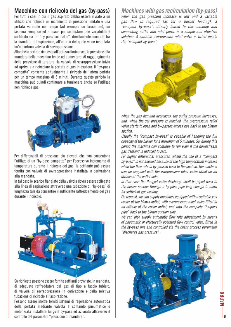
Macchine con ricircolo del gas (by-pass)Per tutti i casi in cui il gas aspirato debba essere inviato a un utilizzo che richieda un incremento di pressione limitato e una portata variabile nel tempo (ad esempio un bruciatore), un sistema semplice ed efficace per soddisfare tale variabilità è costituito da un “by-pass compatto”, direttamente montato tra la mandata e l’aspirazione, all’interno del quale viene installata un’opportuna valvola di sovrappressione. Allorché la portata richiesta all’utilizzo diminuisce, la pressione alla mandata della macchina tende ad aumentare. Al raggiungimento della pressione di taratura, la valvola di sovrappressione inizia ad aprirsi e a ricircolare la portata di gas in esubero. Il “by-pass compatto” consente abitualmente il ricircolo dell’intera portata per un tempo massimo di 5 minuti. Durante questo periodo la macchina può quindi continuare a funzionare anche se l’utilizzo non richiede gas.
Per differenziali di pressione più elevati, che non consentono l’utilizzo di un “by-pass compatto” per l’eccessivo incremento di temperatura durante il ricircolo del gas, la soffiante può essere fornita con valvola di sovrappressione installata in derivazione alla mandata. In tal caso lo scarico flangiato della valvola dovrà essere collegato alla linea di aspirazione attraverso una tubazione di “by-pass” di lunghezza tale da consentire il sufficiente raffreddamento del gas durante il ricircolo.
When the gas demand decreases, the outlet pressure increases, and, when the set pressure is reached, the overpressure relief valve starts to open and by-passes excess gas back to the blower suction.Usually the “compact by-pass” is capable of handling the full capacity of the blower for a maximum of 5 minutes. So, during this period the machine can continue to run even if the downstream gas demand is reduced to zero.For higher differential pressures, where the use of a “compact by-pass” is not allowed because of the high temperature increase when the flow rate is by-passed back to the suction, the machine can be supplied with the overpressure relief valve fitted on an offtake at the outlet side.In that case the flanged valve discharge shall be piped-back to the blower suction through a by-pass pipe long enough to allow for sufficient gas cooling.On request, we can supply machines equipped with a suitable gas cooler at the blower outlet, with overpressure relief valve fitted in an offtake at the cooler outlet, and with the complete “by-pass pipe” back to the blower suction side.We can also supply automatic flow rate adjustment by means of pneumatic or electrically operated flow control valve, fitted in the by-pass line and controlled via the client process parameter “discharge gas pressure”.
Machines with gas recirculation (by-pass)When the gas pressure increase is low and a variable gas flow is required (as for a burner feeding), a “compact by-pass”, directly bolted to the machine and connecting outlet and inlet ports, is a simple and effective solution. A suitable overpressure relief valve is fitted inside the “compact by-pass”.
Su richiesta possono essere fornite soffianti provviste, in mandata, di adeguato raffreddatore del gas di tipo a fascio tubiero, di valvola di sovrappressione in derivazione e della relativa tubazione di ricircolo all’aspirazione.Possono essere inoltre forniti sistemi di regolazione automatica della portata mediante valvola a comando pneumatico o motorizzata installata lungo il by-pass ed azionata attraverso il controllo del parametro “pressione di mandata”.
MAP
RO
9

AccessoriÈ disponibile una linea completa di accessori che comprende, tra l’altro:• filtri a tenuta stagna;• compensatori flangiati di collegamento con soffietto inox;• valvole di ritegno;• manometri e termometri;• pressostati e termostati in esecuzione antideflagrante;• trasduttori di pressione e temperatura a sicurezza intrinseca;• valvole di esclusione manuali ed automatiche;• cabine insonorizzanti.
Macchine azionate tramite inverterNel caso in cui la portata di gas richiesta all’utilizzo sia variabile nel tempo (alimentazione a bruciatore o motore a gas), possono essere fornite soffianti con motore destinato ad essere azionato tramite inverter. Il campo di variazione della velocità di rotazione della macchina (e quindi della frequenza di alimentazione del motore elettrico) sarà definito in funzione delle condizioni di lavoro previste, in particolare del differenziale di pressione tra aspirazione e mandata della macchina. La regolazione della velocità di rotazione potrà essere fatta in funzione del controllo del parametro “pressione di mandata”.
Alcune installazioni /Some installation
Machines controlled via frequency inverterIf the gas demand varies in time (such as for burner or engine feeding), we can supply blowers equipped with a motor intended for control via frequency inverter. The rpm range of the blower (and therefore the output frequency range of the frequency inverter) can be adjusted according to the foreseen operating conditions, and in particular to the expected differential pressure between blower discharge and suction.The speed of rotation of the motor shall be controlled via the “discharge gas pressure” process parameter.
AccessoriesA complete range of accessories is available, including the following:• gas-tight filters;• stainless steel flanged flexible connection bellows;• non return valves;• pressure gauges and thermometers;• explosion-proof pressure switches and temperature switches;• intrinsically-safe pressure and temperature transducers;• manual and automatic cut-off valves;• acoustic enclosures.
10
MAP
RO

50100
150
200
250
300
350
400
450
500
550
600
2060
100
200
300
400
500
600
700
800
900
4080
150
250
350
450
1000
1200
1100
1300
0
50100
150
200
250
300
350
400
450
500
550
600
CL 12
/21CL
14/21
CL 17
/21CL
20/21
CL 23
/21CL
30/21
CL 36
/21CL
42/21
CL 49
/21
CL 98
/1CL
84/1
CL 46
/1
CL 40
/1
CL 34
/1
CL 28
/1
CL 18
/01
CL 15
/01
CL 10
/01
CL 7/
01
CL 3.
6/01
CL 4/
01
CL 22
/01
CL 60
/1CL
72/1
0,25
0,55
0,75
0,75
1,1
1,5
3
2,22,2
33
45,5
5,57,5
7,5
7,5
9,2
9,2
9,211
11
15
4
1,5
4
4
44
44
4
4
5,55,5
5,55,5
7,5
7,5
7,5
7,5
5,55,5
5,5
7,5 5,5
5,5
9,2
11
7,5
9,2
7,5
11
15
11
11 9,2
9,2
9,2
1515
18,5
18,5
4
3
1,5
2,2 1,1
1,1
1,5
1,5
3
3
3
3
3
32,2
2,2
2,2
33 2,2
1,1
0,37
50 H
z
5,5
Cam
po d
i util
izzo
sof
fiant
i a c
anal
e la
tera
le p
er b
ioga
s
Side
cha
nnel
blo
wer
s fo
r bio
gas
- Ran
ge o
f dut
y
The p
erfo
rman
ce cu
rves
“flow
rate
- ou
tlet p
ress
ure”
and
the “
mot
or p
ower
s” sh
own
in th
e lit
erat
ure,
are g
iven,
for i
nfor
mat
ional
pur
pose
s onl
y, at
fixe
d rp
m (5
0Hz –
290
0rpm
) and
fo
r a b
iogas
with
spec
ific w
eight
1.1
4kg/
Nm3 .
The s
uctio
n pr
essu
re is
ass
umed
at 1
0 m
barg
and
the i
nlet
tem
pera
ture
at 3
5°C.
The p
art o
f the
curv
es in
red
colou
r ref
ers t
o the
pre
ssur
e ran
ge in
whi
ch th
e blow
ers f
itted
wi
th a
“com
pact
by-
pass
” can
be u
sed.
Le cu
rve “
porta
ta-p
ress
ione”
e le
“pot
enze
mot
ore”
mos
trate
, uni
cam
ente
a ti
tolo
indi
cativ
o,al
l’int
erno
del
cam
po d
i util
izzo,
si in
tend
ono
per m
acch
ine
a ve
loci
tà fi
ssa
(50H
z – 2
900g
iri/m
in),
e per
un
gas b
iolog
ico d
i pes
o spe
cifico
1,1
4kg/
Nm3 .
La p
ress
ione d
’asp
irazio
ne è
cons
ider
ata
a 10
mba
r g e
la te
mpe
ratu
ra d
’asp
irazio
ne a
35°
C.
La p
arte
di c
urva
in co
lore r
osso
è rif
erita
al c
ampo
di p
ress
ione i
n cu
i è p
ossib
ile l’
utili
zzo
della
m
acch
ina
con
“by-
pass
com
patto
”.
Pressione di mandata [hPa = mbar]Outlet pressure [hPa = mbar]
Porta
ta
[m3 /h
]Flo
w ra
te
[m3 /h
]
Lege
nda
Key
Tipo
mac
chin
a Ma
chine
type
Pote
nza
mot
ore
(kW
) Mo
tor p
ower
(kW
)60
/111
MAP
RO
11
Soffi
anti
a ca
nale
late
rale
per
bio
gas
- Cu
rve
di p
rest
azio
ne
Side
cha
nnel
blo
wer
s fo
r bio
gas
- Per
form
ance
cur
ves
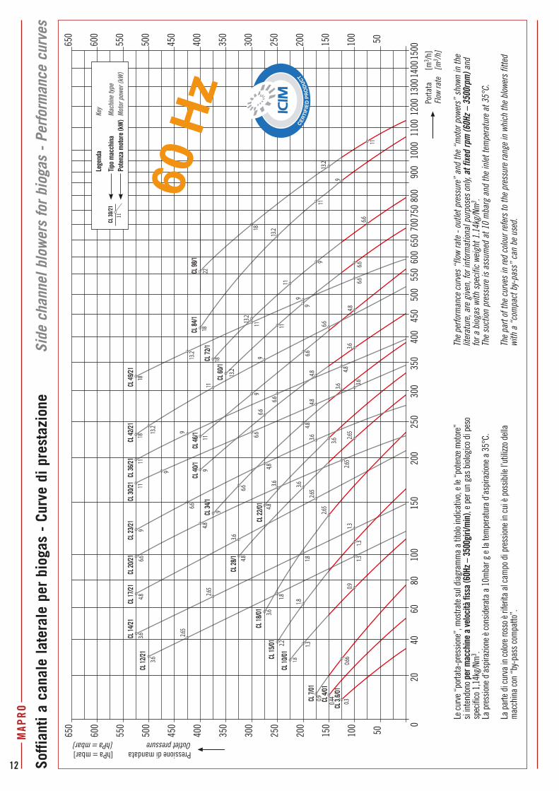
The p
erfo
rman
ce cu
rves
“flow
rate
- ou
tlet p
ress
ure”
and
the “
mot
or p
ower
s” sh
own
in th
e lit
erat
ure,
are g
iven,
for i
nfor
mat
ional
pur
pose
s onl
y, at
fixe
d rp
m (6
0Hz –
350
0rpm
) and
fo
r a b
iogas
with
spec
ific w
eight
1.1
4kg/
Nm3 .
The s
uctio
n pr
essu
re is
ass
umed
at 1
0 m
barg
and
the i
nlet
tem
pera
ture
at 3
5°C.
The p
art o
f the
curv
es in
red
colou
r ref
ers t
o the
pre
ssur
e ran
ge in
whi
ch th
e blow
ers f
itted
wi
th a
“com
pact
by-
pass
” can
be u
sed.
Le cu
rve “
porta
ta-p
ress
ione”
, mos
trate
sul d
iagr
amm
a a
titolo
indi
cativ
o, e l
e “p
oten
ze m
otor
e”
si in
tend
ono
per m
acch
ine
a ve
loci
tà fi
ssa
(60H
z – 3
500g
iri/m
in),
e pe
r un
gas
biolo
gico
di p
eso
spec
ifico
1,1
4kg/
Nm3 .
La p
ress
ione d
’asp
irazio
ne è
cons
ider
ata
a 10
mba
r g e
la te
mpe
ratu
ra d
’asp
irazio
ne a
35°
C.
La p
arte
di c
urva
in co
lore r
osso
è rif
erita
al c
ampo
di p
ress
ione i
n cu
i è p
ossib
ile l’
utili
zzo
della
m
acch
ina
con
“by-
pass
com
patto
”.
CL 4
6/1
CL 3
.6/0
1
CL 4
/01
CL 7
/01
CL 1
0/01CL 1
5/01
CL 1
8/01
CL 1
2/21
CL 1
4/21
CL 2
0/21
CL 1
7/21
CL 2
3/21
CL 3
0/21
CL 3
6/21
CL 4
2/21
CL 4
9/21
CL 2
8/1
CL 2
2/01
CL 3
4/1
CL 4
0/1
CL 6
0/1
CL 7
2/1
CL 8
4/1
CL 9
8/1
9
11
13.2
11
13.218
1822
4.89
2.65
4.8
3.66.6
3.6
2.65
6.6
11
9
11
3.66.6
99
1.84.8
1.3
6.6
1.8
4,8
2.2
3.6
1.83.6
4.8
4.83.6
1.8 1.3
2.65
0.9
2.65
0.31.3
0.44
1.3
0.9
0.66
3.64.8
3.6
4.8
2.65
3.62.6
5
3.63.6
6.6
6.6
6.6
4.84.8
9
6.6
9
6.6
9
1111
9
11
13.2
6.6
18
6.6
119
13.2
13.2
1118
9
18
13.2
50100
150
200
250
300
350
400
450
500
550
600
650
2060
100
200
300
400
500
550
600
700
650
750
800
900
4080
150
250
350
450
1000
1200
1100
1300
1400
1500
0
50100
150
200
250
300
350
400
450
500
550
600
650
60 H
z
Pressione di mandata [hPa = mbar]Outlet pressure [hPa = mbar]
Porta
ta
[m3 /h
]Flo
w ra
te
[m3 /h
]
Lege
nda
Key
Tipo
mac
chin
a Ma
chine
type
Pote
nza
mot
ore
(kW
) Mo
tor p
ower
(kW
)CL
30/
2111
12
MAP
RO

DimensioniDi seguito vengono riportate, fino a pagina 15, a titolo indicativo, le dimensioni delle soffianti monostadio, per biogas o gas naturale, in esecuzione “monoblocco”.Le soffianti si intendono equipaggiate con motore elettrico in esecuzione antideflagrante, modo di protezione “d”, con marcatura specifica Ex II 2 G, marcatura complementare Ex-d IIB T3.Le altezze e i pesi, dati anch'essi a titolo indicativo, si riferiscono a macchine equipaggiate con motore elettrico di potenza la più alta prevista per lo specifico modello di soffiante.Per le dimensioni e le potenze installate di qualunque altra soluzione costruttiva, contattare il Servizio Vendite MAPRO®.
DimensionsBelow, and up to page 15, you can find, for informational purposes only, the dimensions of the single-stage side channel blowers, for biogas or natural gas, in the so-called “CLOSE COUPLED” version.The blowers shown are equipped with the type of protection “d” flameproof electric motor, with specific marking Ex II 2 G, additional marking Ex-d IIB T3. The height and the weight, given as well for informational purposes only, are for the blowers equipped with the motor of the highest power rating amongst those provided for the specific blower model. For the dimensions and the motor power of any other construction feature, please ask MAPRO® Sales Department.
Tipo macchinaMachine type
Potenze motori a 50Hz50Hz motor powers
[kW]A B C ØD E ØF G H I L M N O
PesoWeight
[kg]EN 1092-1
CL 3.6/01 VG 0,25 553 330 406 290 123 10 553 32 143 55 70 320 160 PN16 DN25 30CL 4/01 VG 0,37 553 330 406 290 123 10 553 32 143 55 70 320 160 PN16 DN25 30CL 7/01 VG 0,55 - 0,75 535 380 406 340 125 10 520 32 200 55 70 290 145 PN16 DN40(*) 37CL 10/01 VG 0,75 - 1,1 555 420 411 370 145 10 530 32 210 55 70 300 150 PN16 DN40(*) 41CL 15/01 VG 1,1 - 1,5 580 460 466 410 170 10 545 32 225 55 70 310 155 PN16 DN50(*) 48CL 18/01 VG 1,5 - 2,2 - 3 695 535 536 430 202 10 665 32 280 55 70 368 184 PN16 DN65(**) 72CL 22/01 VG 2,2 - 3 - 4 725 565 561 465 216 10 685 32 295 55 70 390 195 PN16 DN65(**) 94
Dimensioni [mm] - Dimensions [mm]
Soffianti a canale laterale con filtro in aspirazione e curve flangiate in aspirazione e mandataSide channel blowers with inlet filter and inlet and discharge flanged elbows
(*) N.B.: diametro interno flangia: 66mm - (*) N.B.: flange internal diameter: 66mm(**) Flangia a 4 fori - (**) 4-hole flange
I I
NO
G
AL
CH
M E
øF
øD
120°
B
8 8
IF OF
N.B.: per le CL 3.6/01 VG e CL 4/01 VG la posizione dei piedi di supporto è ruotata di 60° rispetto a quanto mostrato in figuraN.B.: the feet position for CL 3.6/01 VG and CL 4/01 VG is turned by 60° compared to the figure
MAP
RO
13

Tipo macchinaMachine type
Potenze motori a 50Hz50Hz motor powers
[kW]A B C ØD E ØF G H I L M N O
PesoWeight
[kg]EN 1092-1CL 3.6/01 VG 0,25 503 323 406 290 115 10 493 32 136 55 70 260 130 PN16 DN25 30CL 4/01 VG 0,37 503 323 406 290 115 10 493 32 136 55 70 260 130 PN16 DN25 30CL 7/01 VG 0,55 - 0,75 570 390 406 340 125 10 570 32 160 55 70 340 170 PN16 DN40(*) 39CL 10/01 VG 0,75 - 1,1 575 425 411 370 145 10 570 32 165 55 70 340 170 PN16 DN40(*) 43CL 15/01 VG 1,1 - 1,5 595 470 446 410 170 10 575 32 180 55 70 340 170 PN16 DN50 50CL 18/01 VG 1,5 - 2,2 710 535 471 430 202 10 695 32 215 55 70 400 200 PN16 DN65(**) 65CL 22/01 VG 2,2 - 3 730 565 541 465 216 10 695 32 230 55 70 400 200 PN16 DN65(**) 81
Tipo macchinaMachine type
Potenze motori a 50Hz50Hz motor powers
[kW]A B C D E ØF G I N O P
PesoWeight
[kg]EN 1092-1CL 28/1 VG 1,5 - 2,2 - 3 725 530 590 460 174 11 655 290 360 180 500 PN16 DN65(*) 88CL 34/1 VG 2,2 - 3 - 4 - 5,5 735 535 665 460 180 11 675 320 380 190 500 PN16 DN65(*) 109CL 40/1 VG 2,2 - 3 - 4 - 5,5 - 7,5 805 580 665 530 190 11 725 325 410 205 570 PN16 DN80 126CL 46/1 VG 3 - 4 - 5,5 - 7,5 815 590 715 530 200 11 745 360 430 215 570 PN16 DN80 136CL 60/1 VG 4 - 5,5 - 7,5 815 590 695 530 200 11 745 380 430 215 570 PN16 DN80 138CL 72/1 VG 5,5 - 7,5 - 9,2 885 655 730 570 220 11 810 340 456 228 610 PN16 DN100 142CL 84/1 VG 5,5 - 7,5 - 9,2 910 715 745 620 255 11 810 365 456 228 660 PN16 DN100 151CL 98/1 VG 5,5 - 7,5 - 9,2 930 745 735 660 265 11 810 355 456 228 700 PN16 DN100 153
Dimensioni [mm] - Dimensions [mm] (*) Flangia a 4 fori – (*) 4-hole flange
Dimensioni [mm] - Dimensions [mm]
DP
I
APD
C
NG
D
øF
B
I0.31
0.31
EO
OFIF
N.B.: per le CL 3.6/01 VG e CL 4/01 VG la posizione dei piedi di supporto è ruotata di 60° rispetto a quanto mostrato in figuraN.B.: the feet position for CL 3.6/01 VG and CL 4/01 VG is turned by 60° compared to the figure
I I
LA
GN
O
CH
EB
120°
øD
øF
M8 8
OFIF
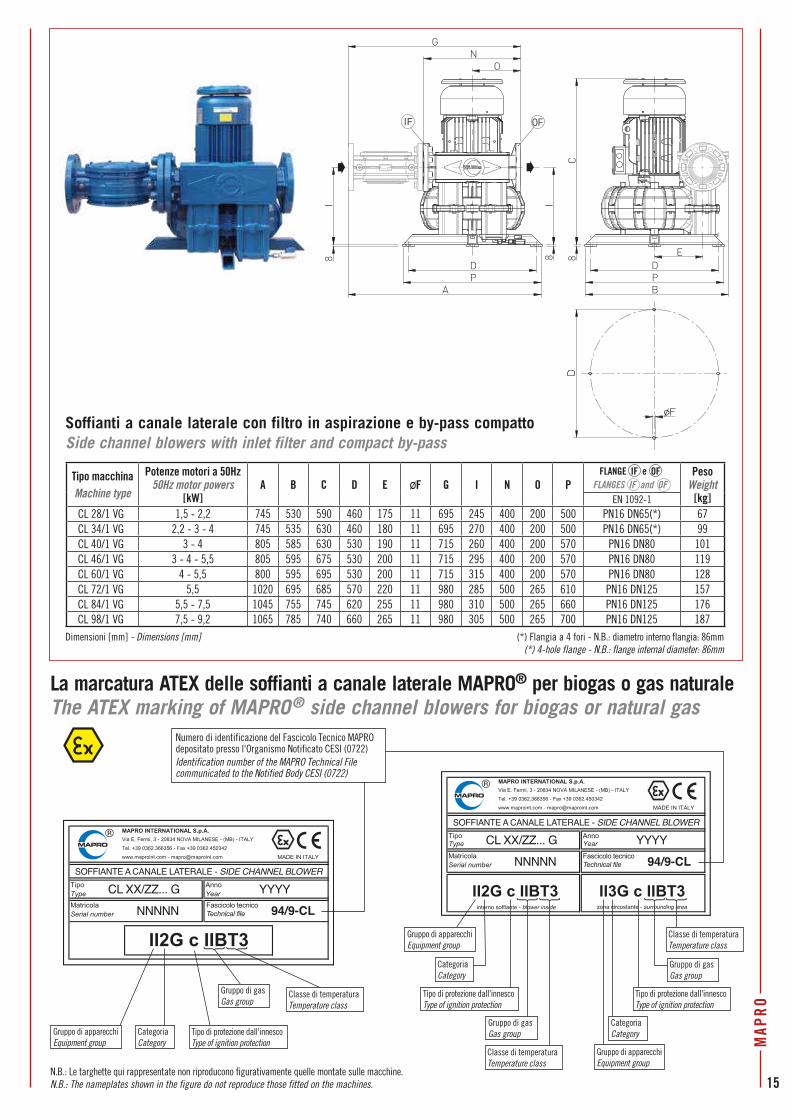
Soffianti a canale laterale con filtro in aspirazione e by-pass compattoSide channel blowers with inlet filter and compact by-pass
Soffianti a canale laterale con filtro in aspirazione e curve flangiate in aspirazione e mandataSide channel blowers with inlet filter and inlet and discharge flanged elbows
(*) N.B.: diametro interno flangia: 56mm - (*) N.B.: flange internal diameter: 56mm(**) Flangia a 4 fori - (**) 4-hole flange14
MAP
RO
Tipo macchinaMachine type
Potenze motori a 50Hz50Hz motor powers
[kW]A B C D E ØF G I N O P
PesoWeight
[kg]EN 1092-1CL 28/1 VG 1,5 - 2,2 745 530 590 460 175 11 695 245 400 200 500 PN16 DN65(*) 67CL 34/1 VG 2,2 - 3 - 4 745 535 630 460 180 11 695 270 400 200 500 PN16 DN65(*) 99CL 40/1 VG 3 - 4 805 585 630 530 190 11 715 260 400 200 570 PN16 DN80 101CL 46/1 VG 3 - 4 - 5,5 805 595 675 530 200 11 715 295 400 200 570 PN16 DN80 119CL 60/1 VG 4 - 5,5 800 595 695 530 200 11 715 315 400 200 570 PN16 DN80 128CL 72/1 VG 5,5 1020 695 685 570 220 11 980 285 500 265 610 PN16 DN125 157CL 84/1 VG 5,5 - 7,5 1045 755 745 620 255 11 980 310 500 265 660 PN16 DN125 176CL 98/1 VG 7,5 - 9,2 1065 785 740 660 265 11 980 305 500 265 700 PN16 DN125 187
La marcatura ATEX delle soffianti a canale laterale MAPRO® per biogas o gas naturaleThe ATEX marking of MAPRO® side channel blowers for biogas or natural gas
SOFFIANTE A CANALE LATERALE - SIDE CHANNEL BLOWER
CL XX/ZZ... G
NNNNN
YYYY
94/9-CLFascicolo tecnico Technical file
interno soffiante - blower inside zona circostante - surrounding area
SOFFIANTE A CANALE LATERALE - SIDE CHANNEL BLOWER
CL XX/ZZ... G
NNNNN 94/9-CL
YYYYFascicolo tecnico Technical file
CategoriaCategory
CategoriaCategory
Gruppo di apparecchiEquipment group
Gruppo di apparecchiEquipment group
Gruppo di apparecchiEquipment group
Tipo di protezione dall'innescoType of ignition protection
Tipo di protezione dall'innescoType of ignition protection
Tipo di protezione dall'innescoType of ignition protection
Gruppo di gasGas group
Gruppo di gasGas group
Classe di temperaturaTemperature class
Classe di temperaturaTemperature class
Classe di temperaturaTemperature class
CategoriaCategory
Gruppo di gasGas group
Soffianti a canale laterale con filtro in aspirazione e by-pass compattoSide channel blowers with inlet filter and compact by-pass
Dimensioni [mm] - Dimensions [mm]
DP
I
APD
C
NO
G
B
E
I8 8 8
OFIF
(*) Flangia a 4 fori - N.B.: diametro interno flangia: 86mm (*) 4-hole flange - N.B.: flange internal diameter: 86mm
N.B.: Le targhette qui rappresentate non riproducono figurativamente quelle montate sulle macchine. N.B.: The nameplates shown in the figure do not reproduce those fitted on the machines.
Numero di identificazione del Fascicolo Tecnico MAPRO depositato presso l'Organismo Notificato CESI (0722)Identification number of the MAPRO Technical File communicated to the Notified Body CESI (0722)
MAP
RO
15

SOFFIANTI, Serie CL... -M HG, per BIOGAS e GAS NATURALEBLOWERS, CL... -M HG Series, for BIOGAS and NATURAL GASGeneralità e soluzioni costruttivein conformità alla Direttiva 2014/34/UE (ATEX)Le soffianti a canale laterale MAPRO®, Serie CL…-M HG, sono state messe a punto per la compressione, a limitati valori di pressione, di gas combustibili, quali gas biologico o gas naturale, in luoghi pericolosi classificati come Zona 2.Sono quindi apparecchiature rientranti nel Gruppo II, così come definito dalla Direttiva 2014/34/UE, di Categoria 3, con motore elettrico a due poli, in esecuzione antiscintilla, modo di protezione “n”, con marcatura specifica Ex II 3G, marcatura complementare Ex-nA II T3.Le loro principali peculiarità costruttive sono le seguenti:• corpo e girante interamente realizzati in lega di alluminio
antiscintilla;• sigillatura tra i fondi costituenti il corpo macchina;• tenuta sull’albero realizzata con speciali anelli a doppio
labbro che non richiedono lubrificazione.La soluzione costruttiva è nella cosiddetta “esecuzione MONOBLOCCO”. La flangia anteriore del motore elettrico è cioè direttamente fissata al corpo macchina e la girante, bilanciata dinamicamente, è calettata sul capo d’albero del motore stesso. Per il collegamento alle tubazioni gas sono previste flange filettate in aspirazione e mandata.
Applicazioni più comuni • Aspirazione di biogas da discariche controllate e invio a torcia;• Aspirazione di gas da serbatoi, impianti o terreni da bonificare
e invio a torcia.
Generalities and construction features in conformity with the 2014/34/EU Directive (ATEX)
The MAPRO® side channel blowers CL...-M HG Series have been designed to be used for the compression,
at low pressure values, of combustible gases, such as biological or natural gas, in hazardous places classified as Zone 2.They are therefore blowers designed in order to fall within the Equipment-Group II, as defined by the 2014/34/EU Directive, Category 3, equipped with two-pole, type of protection “n” non-sparking
motor with specific marking Ex II 3G, additional marking Ex-nA II T3.The main construction features of these machines are:
• casing and impeller made completely of spark proof aluminium alloy;
• casing halves sealed;• shaft sealing by special double-lip seals which do not
require lubrication.The blowers are manufactured in the so-called “CLOSE COUPLED” version - i.e., a flange mounted electric motor is bolted to the blower casing; the impeller, which
is dynamically balanced, is fitted directly onto the motor shaft extension.
The machines are fitted with threaded flanges for the connection to the inlet and discharge gas pipes.
The most common fields of application • Landfill biogas recovery to feed torch;• Tank, plant or contaminated soil gas recovery to feed torch.
Tipo macchinaMachine Type
A B C D E F G H I L M N O P Q ØR S
Attacchi (”gas)Connections (”gas)
PesoWeight
[kg]aspir.inlet Ø1 mand.
outlet Ø2
CL 30-M HG 316 252 257 205 228 11,5 57,5 45 83 108 12,5 49,5 57 39 8 10 2,5 1” 1/4 1” 1/4 15CL 40-M HG 313 287 312 225 255 15 60 52,5 95 130 17,5 81 60 52 8 12 3 1” 1/2 1” 1/2 23CL 50-M HG 386 328 347 260 295 17,5 70 60 115 155 20 70 65 48 8 14 4 2” 2” 27CL 60-M HG 450 382 391 290 325 17,5 82,5 62,5 140 180 20 70 90 48 8 15 4,5 2” 2” 35CL 80-M HG 488 451 473 356 394 19 102 76 170 217 23,5 92 100 65 8 15 6 2” 1/2 2” 1/2 51
Dimensioni [mm] Dimensions [mm]
Dimensioni / Dimensions
H HG GDF FE
PQ
PQ
C
S
IM MLO
N
B A
1 2 4 fori-holes øR
16
MAP
RO
La marcatura ATEX delle soffianti MAPRO®, Serie CL...-M HG, per biogas o gas naturaleThe ATEX marking of MAPRO® blowers, CL...-M HG Series, for biogas or natural gas
interno soffiante - blower inside zona circostante - surrounding area
SOFFIANTE A CANALE LATERALE - SIDE CHANNEL BLOWER
CL XX-M HG
NNNNN 94/9-CL
YYYYFascicolo tecnico Technical file
CategoriaCategory
Gruppo di apparecchiEquipment group
Tipo di protezione dall'innescoType of ignition protection
Gruppo di apparecchiEquipment group
Tipo di protezione dall'innescoType of ignition protection
Classe di temperaturaTemperature class
CategoriaCategory
Gruppo di gasGas group
Gruppo di gasGas group
N.B.: La targhetta qui rappresentata non riproduce figurativamente quella montata sulle macchine. N.B.: The nameplate shown in the figure does not reproduce the one fitted on the machines.
Classe di temperaturaTemperature class
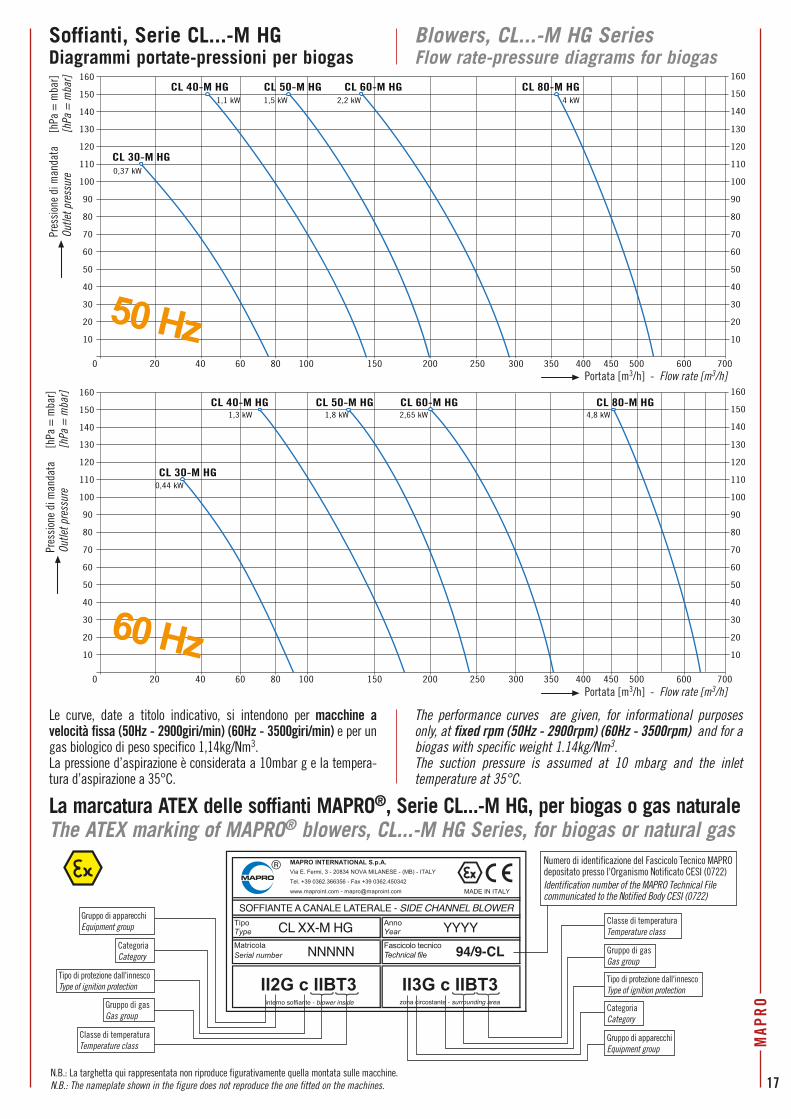
Soffianti, Serie CL...-M HGDiagrammi portate-pressioni per biogas
Blowers, CL...-M HG SeriesFlow rate-pressure diagrams for biogas
20 60 100 200 300 400 500 600 70040 80 150 250 350 4500
10
20
30
40
50
60
70
80
90
100
110
120
130
CL 40-M HG1,1 kW
CL 50-M HG1,5 kW
CL 60-M HG2,2 kW
CL 80-M HG4 kW
10
20
30
40
50
60
70
80
90
100
110
120
130
140
150
160
140
150
160
CL 30-M HG0,37 kW
Le curve, date a titolo indicativo, si intendono per macchine a velocità fissa (50Hz - 2900giri/min) (60Hz - 3500giri/min) e per un gas biologico di peso specifico 1,14kg/Nm3.La pressione d’aspirazione è considerata a 10mbar g e la tempera-tura d’aspirazione a 35°C.
The performance curves are given, for informational purposes only, at fixed rpm (50Hz - 2900rpm) (60Hz - 3500rpm) and for a biogas with specific weight 1.14kg/Nm3.The suction pressure is assumed at 10 mbarg and the inlet temperature at 35°C.
Portata [m3/h] - Flow rate [m3/h]
Portata [m3/h] - Flow rate [m3/h]
Pres
sion
e di
man
data
[h
Pa =
mba
r]Ou
tlet p
ress
ure
[hPa
= m
bar]
Pres
sion
e di
man
data
[h
Pa =
mba
r]Ou
tlet p
ress
ure
[hPa
= m
bar]
Numero di identificazione del Fascicolo Tecnico MAPRO depositato presso l'Organismo Notificato CESI (0722)Identification number of the MAPRO Technical File communicated to the Notified Body CESI (0722)
20 60 100 200 300 400 500 600 70040 80 150 250 350 4500
10
20
30
40
50
60
70
80
90
100
110
120
130
CL 40-M HG1,3 kW
CL 50-M HG1,8 kW
CL 60-M HG2,65 kW
CL 80-M HG4,8 kW
10
20
30
40
50
60
70
80
90
100
110
120
130
140
150
160
140
150
160
CL 30-M HG0,44 kW
50 Hz
60 Hz
MAP
RO
17

SOFFIANTE TBT per BIOGAS e GAS NATURALETBT BLOWER for BIOGAS and NATURAL GAS
Principio di funzionamentoLa soffiante TBT è una macchina con canale toroidale periferico, come quelle a canale laterale, ma con una girante e un canale di concezione altamente innovativa, frutto di un lungo lavoro di ricerca e sperimentazione. Il principio di funzionamento e i vantaggi sono gli stessi delle soffianti a canale laterale. Tuttavia, le palette a profilo alare della girante e il canale con nocciolo centrale consentono di raggiungere prestazioni prossime a quelle delle soffianti volumetriche a lobi rotanti.
Generalità e soluzioni costruttive in conformità alla Direttiva 2014/34/UE (ATEX)Le peculiarità costruttive sono le stesse delle soffianti a canale laterale. Le soffianti TBT destinate alla compressione di gas combustibili, quali gas biologico o gas naturale, sono tuttavia sempre costruite nella versione con proprio albero e cuscinetti.L’accoppiamento al motore elettrico può essere realizzato tramite giunto elastico o, assai più spesso, a mezzo cinghie e pulegge.Infatti la soffiante TBT, nella versione per gas combustibili, è progettata per un’ampia gamma di velocità di rotazione (da 2000 a 5000 giri/min), e questo consente di coprire, con una sola taglia di macchina, un larghissimo campo di funzionamento.
Applicazioni più comuni • Aspirazione di biogas da discariche controllate e invio a
torcia, a bruciatore o motore a gas;• aspirazione di gas da serbatoi, impianti o terreni da
bonificare e invio a torcia o a bruciatore;• aspirazione di biogas da gasometro, di gas naturale da rete
o da gasometro e invio a bruciatore o motore a gas.
Operating principle The TBT is a machine with a peripheral toroidal channel, and therefore similar to side channel blowers, but featuring a
revolutionary impeller and channel design, developed through long research and testing. The operating principle and advantages are the same
as side channel blowers. However the wing contour of the impeller vanes and the peripheral channel with
the central core, both contribute to the achievement of performances similar to that of positive displacement machines.
Generalities and construction features in conformity with the 2014/34/EU Directive (ATEX)
Construction features are the same as those for side channel blowers. But, differently from the side channel machines, the TBT blowers designed to extract or compress combustible gases, such as biological or natural gas, are always manufactured with their own shaft and bearings. Occasionally they are coupled to an electric motor via a flexible shaft coupling, but more frequently via a belt drive. The latter permits a wide range of operating speeds; from 2000 to 5000 rpm. The advantage is that one unit can cover a wide operating range.
The most common fields of application • Landfill biogas recovery to feed torch, burner or gas
engine;• tank, plant or contaminated soil gas recovery to feed torch
or burner;• extraction of biogas from gasometer, natural gas from
pipeline or gasometer, and burner or gas engine feeding.
18
MAP
RO

Soffianti TBT con ricircolo del gasPer tutti i casi in cui il gas aspirato debba essere inviato a un utilizzo che richieda una portata variabile nel tempo, la soffiante TBT può essere fornita con valvola di sovrappressione installata in derivazione alla mandata.Lo scarico flangiato della valvola dovrà essere collegato alla linea di aspirazione attraverso una tubazione di “by-pass” di lunghezza tale da consentire il sufficiente raffreddamento del gas durante il ricircolo.Allorchè la portata richiesta all’utilizzo diminuisce, la pressione alla mandata della macchina tende ad aumentare.Al raggiungimento della pressione di taratura, la valvola di sovrappressione inizia ad aprirsi e a ricircolare la portata di gas in esubero.Su richiesta possono essere fornite soffianti TBT provviste, in mandata, di adeguato raffreddatore del gas di tipo a fascio tubiero, di valvola di sovrappressione in derivazione e della relativa tubazione di ricircolo all’aspirazione.Possono essere inoltre forniti sistemi di regolazione automatica della portata mediante valvola a comando pneumatico o motorizzata installata lungo il by-pass ed azionata attraverso il controllo del parametro “pressione di mandata”.
Soffianti TBT azionate tramite inverterNel caso in cui la portata di gas richiesta all’utilizzo sia variabile nel tempo (ad esempio nel caso di alimentazione a bruciatore o motore a gas), possono essere fornite soffianti TBT accoppiate a motore destinato ad essere azionato tramite inverter.Il campo di variazione della velocità di rotazione della soffiante (e quindi della frequenza di alimentazione del motore elettrico) sarà definito in funzione delle condizioni di lavoro previste, in particolare del differenziale di pressione tra aspirazione e mandata della macchina. La regolazione della velocità di rotazione potrà essere fatta in funzione del controllo del parametro “pressione di mandata”
TBT blowers with gas recirculation (by-pass)When the gas has to feed a burner or when a variable gas flow is required, the TBT blowers can be supplied with the overpressure relief valve fitted on an offtake at the outlet side.The flanged valve discharge shall be piped-back to the blower suction through a by-pass pipe long enough to allow for the sufficient gas cooling.When the gas demand decreases, the outlet pressure increases, and, when the set pressure is reached, the overpressure relief valve starts to open and by-passes excess gas back to the blower suction.On request, we can supply TBT blowers equipped with a suitable gas cooler at the blower outlet, with overpressure relief valve fitted in an offtake at the cooler outlet, and with the complete “by-pass pipe” back to the blower suction side.We can also supply automatic flow rate adjustment by means of pneumatic or electrically operated flow control valve, fitted in the by-pass line and controlled via the client process parameter “discharge gas pressure”.
AccessoriÈ disponibile una linea completa di accessori che comprende, tra l’altro:• filtri a tenuta stagna;• compensatori flangiati di collegamento con soffietto inox;• valvole di ritegno;• manometri e termometri;• pressostati e termostati in esecuzione antideflagrante;• trasduttori di pressione e temperatura a sicurezza intrinseca;• valvole di esclusione manuali ed automatiche;• cabine insonorizzanti.
TBT blowers controlled via frequency inverterIf the gas demand varies in time (such as for burner or engine feeding), we can supply TBT blowers coupled to an electric motor intended for control via frequency inverter.The rpm range of the blower (and therefore the output frequency range of the frequency inverter) can be adjusted according to the foreseen operating conditions, and in particular to the expected differential pressure between blower discharge and suction.The speed of rotation of the motor shall be controlled via the “discharge gas pressure” process parameter.
AccessoriesA complete range of accessories is available, including the following:• gas-tight filters;• stainless steel flanged flexible connection bellows;• non return valves;• pressure gauges and thermometers;• explosion-proof pressure switches and temperature switches;• intrinsically-safe pressure and temperature transducers;• manual and automatic cut-off valves;• acoustic enclosures.
MAP
RO
19

100
200
300
400
500
600
700
800
900hPa gbar g
100 200 300 400 500 600 700 800 900 1000 1100 1200 1400 1600 1800 20001300 1500 1700 19000
0,1
0,2
0,3
0,4
0,5
0,6
0,7
0,8
0,9
0
15
11
9,2
7,5 11
15
15
22
37
45
45
55 75
55
4537
37
30
30
30
22
22
18,5
18,5
22
18,5
30
SOFFIANTE TBT - TBT BLOWER
TBT GNNNNN 94/9-TBT
YYYY
SOFFIANTE TBT - TBT BLOWER
TBT GNNNNN 94/9-TBT
YYYY
interno soffiante - blower inside zona circostante - surrounding area
CategoriaCategory
CategoriaCategory
Gruppo di apparecchiEquipment group
Gruppo di apparecchiEquipment group
Gruppo di apparecchiEquipment group
Tipo di protezione dall'innescoType of ignition protection
Tipo di protezione dall'innescoType of ignition protection
Tipo di protezione dall'innescoType of ignition protection
Gruppo di gasGas group
Gruppo di gasGas group
Classe di temperaturaTemperature class
Classe di temperaturaTemperature class
Classe di temperaturaTemperature class
Numero di identificazione del Fascicolo Tecnico MAPRO depositato presso l'Organismo Notificato CESI (0722)Identification number of the MAPRO Technical File communicated to the Notified Body CESI (0722)
CategoriaCategory
Gruppo di gasGas group
La marcatura ATEX della soffiante TBT per biogas o gas naturaleThe ATEX marking of the TBT blower for biogas or natural gas
TBT per biogas - Campo di utilizzo TBT for biogas – Range of duty
The performance curves “flow rate - outlet pressure” and the “motor powers” shown in the literature, are given, for informational purposes only, at fixed rpm and for a biogas with specific weight 1.14kg/Nm3.The suction pressure is assumed at 10 mbarg and the inlet tempera-ture at 35°C.
Le curve “portata-pressione” e le “potenze motore” mostrate, unicamente a titolo indicativo, all’interno del campo di utilizzo, si intendono per soffiante TBT a velocità fissa e per un gas biologico di peso specifico 1,14kg/Nm3. La pressione d’aspirazione è considerata a 10mbar g e la temperatura d’aspirazione a 35°C.
Pres
sion
e di
man
data
- O
utlet
pre
ssur
e
Portata [m3/h] - Flow rate [m3/h]
Legenda KeyPotenza motore (kW) Motor power (kW)18,5
N.B.: Le targhette qui rappresentate non riproducono figurativamente quelle montate sulle macchine. N.B.: The nameplates shown in the figure do not reproduce those fitted on the machines.
2000 giri/min - rpm
2500 giri/min - rpm
2900 giri/min - rpm
3500 giri/min - rpm4000 giri/min - rpm
4500 giri/min - rpm
20
MAP
RO

DimensioniQui sotto e a pagina successiva vengono riportate, a titolo indicativo, le dimensioni delle soffianti TBT per biogas o gas naturale.I pesi, dati anch'essi a titolo indicativo, si intendono per macchine equipaggiate con motore elettrico in esecuzione antideflagrante, modo di protezione “d”, con marcatura specifica Ex II 2 G, marcatura complementare Ex-d IIB T3. Nel caso di accoppiamento tramite giunto elastico, il motore elettrico è sempre a due poli. Per accoppiamento a mezzo cinghie e pulegge, il motore elettrico può essere a due o quattro poli a seconda delle condizioni di funzionamento previste.
DimensionsBelow and on the next page you can find, for informational purposes only, the dimensions of the TBT blowers for biogas or natural gas.The weights, given as well for informational purposes only, are for blowers equipped with the type of protection “d” flameproof electric motor, with specific marking Ex II 2 G, additional marking Ex-d IIB T3.When the TBT blower shaft is coupled to the motor via flexible coupling, the electric motors are always two-pole type. For coupling via belt drives, the electric motors could be two-pole or four-pole type, depending on the expected operating conditions.
Potenza motoreMotor power
[kW]A (**) B C D E ØF G (*) H I L M N O P Q R (*) S T U (**)
PesoWeight
[kg] (**)
11 1295
970 1070 995 300 20 825 695 860 1200 1000 600 550 160 945 255 95 220
- 345
15 1295 - 359
18,5 1295 - 373
22 1315 20 384
30 1315 20 419
37 1315 20 439
Dimensioni [mm] - Dimensions [mm]La flangia di ingresso al filtro montato all’aspirazione della soffiante TBT e la flangia in mandata sono:- PN16 DN100 EN1092-1 per portate ≤ 600m3/h- PN16 DN125 EN1092-1 per portate > 600m3/h
(*) Le quote si riferiscono a macchine con flange in ingresso e uscita PN16 DN125 EN1092-1
(**) Le quote e i pesi possono variare in funzione della marca di motore elettrico installato
The inlet flange of the filter fitted on TBT blower suction and the discharge flange are:- PN16 DN100 EN1092-1 for flow rates ≤ 600m3/h- PN16 DN125 EN1092-1 for flow rates > 600m3/h (*) Dimensions are for machines with inlet and outlet flanges PN16
DN125 EN1092-1(**) Dimensions and weights could vary depending on the electric motor
brand
Soffiante TBT con filtro in aspirazione e accoppiamento a motore tramite giunto elasticoTBT blower with inlet filter and coupled to the electric motor via flexible shaft coupling
MAP
RO
21

Soffiante TBT con filtro in aspirazione e accoppiamento a motore a mezzo cinghie e puleggeTBT blower with inlet filter and coupled to the electric motors via belt drives
Per motori elettrici da 45 e 55kWFor 45 and 55kW electric motors
Potenza motoreMotor power [kW] A (**) B C D E ØF G (*) H I L M N O P Q R (*) T Peso / Weight
[kg] (**)11
670
1670 1020 330 300 20 835 645 810 650 510 1340 1280 160 895 265 220
33515 350
18,5 37522
745395
30 42037 490
Dimensioni [mm] / Dimensions [mm]
La flangia di ingresso al filtro montato all’aspirazione della soffiante TBT e la flangia in mandata sono:- PN16 DN100 EN1092-1 per portate ≤ 600m3/h- PN16 DN125 EN1092-1 per portate > 600m3/h e ≤ 1400m3/h- PN16 DN150 EN1092-1 per portate > 1400m3/h(*) Le quote si riferiscono a macchine con flange in ingresso e uscita
PN16 DN150 EN1092-1(**) Le quote e i pesi possono variare in funzione della marca del motore
elettrico
The inlet flange of the filter fitted on TBT blower suction and the discharge flange are:- PN16 DN100 EN1092-1 for flow rates ≤ 600m3/h- PN16 DN125 EN1092-1 for flow rates > 600m3/h and ≤ 1400m3/h- PN16 DN150 EN1092-1 for flow rates > 1400m3/h (*) Dimensions are for machines with inlet and outlet flanges
PN16 DN150 EN1092-1(**) Dimensions and weights could vary depending on the electric
motor brand
La flangia di ingresso al filtro montato all’aspirazione della soffiante TBT e la flangia in mandata sono:- PN16 DN125 EN1092-1 per portate ≤ 1400m3/h- PN16 DN150 EN1092-1 per portate > 1400m3/h(*) Le quote si riferiscono a macchine con flange in ingresso e uscita
PN16 DN150 EN1092-1(**) Le quote e i pesi possono variare in funzione della marca del motore
elettrico
The inlet flange of the filter fitted on TBT blower suction and the discharge flange are:- PN16 DN125 EN1092-1 for flow rates ≤ 1400m3/h- PN16 DN150 EN1092-1 for flow rates > 1400m3/h (*) Dimensions are for machines with inlet and outlet flanges PN16
DN150 EN1092-1(**) Dimensions and weights could vary depending on the electric
motor brand
Per motori elettrici fino a 37kW For electric motors up to 37kW
Potenza motoreMotor power [kW] A (**) B C D E ØF G (*) H I L M N O P Q R (*) T Peso / Weight
[kg]45 810
1760 1070 330 300 20 835 695 860 800 750 1350 1150 240 945 265 220530
55 840 555Dimensioni [mm] / Dimensions [mm]
22
MAP
RO

Principio di funzionamentoI ventilatori centrifughi MAPRO®, Serie MCF, sono composti da:
• un condotto di aspirazione che convoglia il gas aspirato all’ingresso,
coassiale all’albero, della girante;• una girante chiusa a ingresso assiale e
uscita radiale;• una voluta di scarico toroidale a uscita
tangenziale.La rotazione della girante palettata imprime un’azione centrifuga al gas aspirato che viene spinto verso l’esterno fino a fuoriuscire nella voluta toroidale che, a sua volta, convoglia la vena fluida verso un boccaglio di mandata tangenziale.La compressione del gas di processo avviene attraverso l’incremento di energia cinetica dato al fluido dalla girante palettata e per la successiva conversione di tale energia cinetica in energia di pressione nella voluta di scarico.
Generalità e soluzioni costruttive in conformità alla Direttiva 2014/34/UE (ATEX)I ventilatori centrifughi MAPRO®, Serie MCF, destinati alla compressione di gas combustibili, quali gas biologico o gas naturale, sono apparecchi rientranti nel Gruppo II così come definito dalla Direttiva 2014/34/UE, di Categoria 2 sia per l’ambiente circostante che per il loro interno.Le loro principali peculiarità costruttive sono le seguenti:• corpo in fusione di alluminio, girante in lega di alluminio
con palette cianfrinate, mozzo portacuscinetti in ghisa con coperchi in alluminio, albero in acciaio;
• trattamento di impregnazione con Loctite delle parti destinate a contenere il gas;
• sigillatura tra i fondi costituenti il corpo macchina;• tenuta sull’albero realizzata con una coppia di anelli
speciali a doppio labbro la cui lubrificazione è assicurata da un ingrassatore automatico.
VENTILATORI CENTRIFUGHI, Serie MCF, per BIOGAS e GAS NATURALECENTRIFUGAL FANS, MCF Series, for BIOGAS and NATURAL GAS
Operating principle The MAPRO® centrifugal fans, MCF
Series, are made of:• an intake duct conveying the
aspirated gas to the impeller inlet, which is coaxial to the shaft;• a closed impeller with axial flow inlet and radial
flow exit;• a toroidal discharge volute with
tangential exit.While the impeller is rotating, the
vanes give a centrifugal thrust to the aspirated gas which is forced outwards into the
toroidal discharge volute. The volute collects the gas delivering it to a tangential nosepiece.The compression occurs through the
increment of kinetic energy given to the gas by the vanes of the impeller and the subsequent conversion of the kinetic energy
into static pressure in the discharge volute.
Generalities and construction features in conformity with
the 2014/34/EU Directive (ATEX)The MAPRO® centrifugal fans, MCF Series, to be used for extraction or compression of combustible gases, such as biological or natural gas, have been designed in order to fall within the Equipment-Group II as defined by the 2014/34/EU Directive, Category 2 both for the surrounding area conditions and for the internals of the machine. Their main construction features are the following:• aluminium casted casing, impeller made of spark proof
aluminium alloy with caulked vanes, bearings housing made in cast iron and with aluminium casted caps, shaft in carbon steel;
• casing impregnated with Loctite;• casing halves sealed;• shaft sealing by a pair of special double-lip seals whose
lubrication is provided by an automatic lubricator.
MAP
RO
23

L’accoppiamento al motore elettrico è in generale realizzato tramite cinghie e pulegge, con carter di protezione della trasmissione in materiale antiscintilla. Sono tuttavia previste sia la costruzione con accop-piamento al motore elettrico tramite giunto elastico, sia la costruzione nella cosiddetta “esecuzione MONOBLOCCO” (MCF...CC); in quest’ultimo caso la flangia anteriore del motore elettrico è direttamente fissata al corpo macchina e la girante, bilanciata dinamicamente, è calettata sul capo d’albero del motore stesso.Per installazioni in Zona 1 i motori elettrici sono in esecuzione antideflagrante, modo di protezione “d”, con marcatura specifica Ex II 2 G, marcatura complementare Ex-d IIB T3.Nel caso in cui l’ambiente circostante venga invece classificato come Zona 2, per la quale sono ammesse, per il Gruppo II, apparecchiature di Categoria 3, il motore elettrico viene fornito in esecuzione antiscintilla, modo di protezione “n”, con marcatura specifica Ex II 3 G, marcatura complementare Ex-nA II T3.
Per particolari condizioni di impiego e/o in funzione della composizione del gas trattato, possono essere proposti ventilatori in esecuzione speciale con, ad esempio, trattamenti di ossidazione anodica sulle parti in fusione d’alluminio e girante con palettatura in acciaio inox; e ancora, tra la coppia di anelli speciali di tenuta sull’albero può essere immesso un fluido di sbarramento.
VantaggiNon ci sono parti in strisciamento relativo durante il funzionamento. Non essendoci attrito e non essendo quindi necessaria nessuna lubrificazione, il gas convogliato non viene assolutamente inquinato. Oltre a ciò, i maggiori vantaggi nel-l’utilizzo dei ventilatori centrifughi MCF MAPRO® sono:• massima semplicità di
installazione;• rumorosità assai contenuta;• assenza di vibrazioni;• assenza di pulsazioni nel
flusso di gas trattato e assenza del fenomeno di pompaggio;
• minima manutenzione.
The centrifugal fans are generally coupled to the electric motor via belt drive and the safety drive guard is made of
spark-free material. We can also offer machines
coupled to the electric motor via flexible
shaft coupling and centrifugal fans m a n u fa c tu r e d in the so-called “CLOSE COUPLED” version (MCF...CC type) - i.e. a flange mounted electric motor is bolted to the fan casing
and the impeller, which is dynamically balanced, is fitted directly
onto the motor shaft extension.If the area surrounding the equipment is classified as Zone 1, the electric motors are flameproof, type of protection “d”, with specific marking Ex II 2 G, additional marking Ex-d IIB T3.If the area surrounding the equipment is classified as Zone 2, where, for the Group II, Category 3 equipments are accepted, the machine could be equipped with the type of protection “n” non-sparking motor, with specific marking Ex II 3 G, additional marking Ex-nA II T3.
For particular duties and/or in function of the gas composition, fans with special construction features could be proposed; for example with the aluminium casted parts treated with anodic oxidation and the blades of the impeller in stainless steel; and it is also possible to fit the pair of double-lip seals on the shaft so that they are suitable for a barrier fluid in between.
AdvantagesThe rotating parts are not in contact with the casing during rotation. There is therefore no friction during operation and thus no internal lubrication is necessary.
The gas moving through the machine remains
uncontaminated and completely oil-free. The other main advan- tages of using the MAPRO® MCF centri-fugal fans are:
• easy installation;• low noise level;
• no vibration;• pulsation free gas flow
and no surge;• minimal maintenance.
24
MAP
RO

Applicazioni più comuni Le applicazioni più comuni per i ventilatori centrifughi MAPRO®, Serie MCF, sono:• aspirazione di biogas da gasometro, di gas
naturale da rete o da gasometro e invio a bruciatore o motore a gas;
• aspirazione di gas da serbatoi o da impianti da bonificare e invio a torcia o a bruciatore;
• trasferimento del biogas dall'impianto di produzione a stazioni di cogenerazione remote.La curva caratteristica “portata - pressione” e l’assenza del fenomeno di pompaggio, rendono i ventilatori centrifughi MAPRO® le macchine ideali per applicazioni nelle quali la portata di gas da aspirare può variare, anche notevolmente, nel tempo. Infatti, poichè la curva caratteristica “portata - pressione” è piuttosto piatta, il ventilatore può immediatamente reagire alle variazioni di portata spostando, senza alcun problema di funzionamento, il punto di lavoro lungo la curva caratteristica stessa.
AccessoriÈ disponibile una linea completa di accessori che comprende, tra l’altro:• filtri a tenuta stagna;• compensatori flangiati di collegamento con soffietto inox;• valvole di ritegno;• manometri e termometri;• pressostati e termostati in esecuzione antideflagrante;• trasduttori di pressione e temperatura a sicurezza intrinseca;• valvole di esclusione manuali ed automatiche;• cabine insonorizzanti.Il Servizio Commerciale MAPRO®, in sinergia con il proprio Servizio Tecnico, è in grado di studiare e proporre, sulla base delle richieste dei clienti, le macchine accessoriate in modo da rispondere al meglio alle esigenze specifiche e alle peculiarità dell’impianto.
The most common fields of application The most common fields of application for MAPRO® centrifugal fans, MCF Series, are:
• extraction of biogas from gasometer, natural gas from pipeline or gasometer, and burner or gas engine feeding;
• tank or plant gas recovery to feed torch or burner;
• biogas transfer from the pro- duction plant to remote satellite CHP units.
The typical “flow rate - pressure” curve, rather flat at fixed rpm, and the absence of surging when decreasing the gas flow, make the MAPRO® centrifugal fans the ideal machines for all the applications in which the gas flow rate could vary, even considerably. In fact, as the "flow rate - pressure" curve is quite flat on a large range of duty, the fan can immediately and safely react to the flow variations by moving its operating point along the curve itself.
AccessoriesA complete range of accessories is available, including the following:• gas-tight filters;
• stainless steel flanged flexible connection bellows;
• non return valves;• pressure gauges and thermometers;• explosion-proof pressure switches and
temperature switches;• intrinsically-safe pressure and
temperature transducers;• manual and automatic cut-off valves;• acoustic enclosures.MAPRO® Sales Department, in synergy with the Engineering Department, could design and quote, according to customer requirements, the machines complete with the accessories that better meet the specific needs and peculiarities of the plant.
MAP
RO
25
Dimensioni Dimensions
H
N
DE
A
P
L
C
=G
== =F
OM
B
I
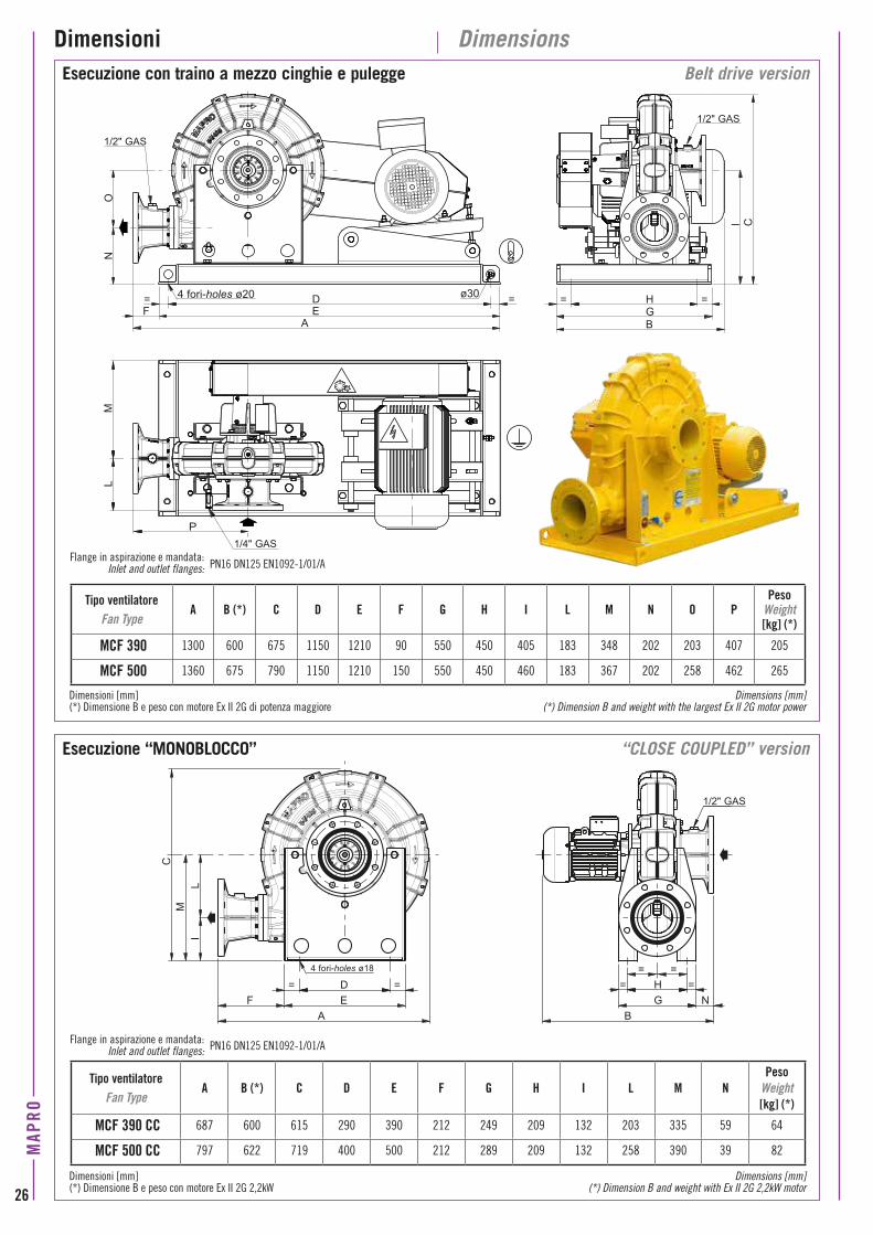
Esecuzione con traino a mezzo cinghie e pulegge
Esecuzione “MONOBLOCCO”
Belt drive version
“CLOSE COUPLED” version
Tipo ventilatoreFan Type
A B (*) C D E F G H I L M N O PPeso
Weight[kg] (*)
MCF 390 1300 600 675 1150 1210 90 550 450 405 183 348 202 203 407 205
MCF 500 1360 675 790 1150 1210 150 550 450 460 183 367 202 258 462 265
Tipo ventilatoreFan Type
A B (*) C D E F G H I L M NPeso
Weight[kg] (*)
MCF 390 CC 687 600 615 290 390 212 249 209 132 203 335 59 64
MCF 500 CC 797 622 719 400 500 212 289 209 132 258 390 39 82
Dimensioni [mm] Dimensions [mm](*) Dimensione B e peso con motore Ex II 2G di potenza maggiore (*) Dimension B and weight with the largest Ex II 2G motor power
Dimensioni [mm] Dimensions [mm](*) Dimensione B e peso con motore Ex II 2G 2,2kW (*) Dimension B and weight with Ex II 2G 2,2kW motor
Flange in aspirazione e mandata:Inlet and outlet flanges:
Flange in aspirazione e mandata:Inlet and outlet flanges:
PN16 DN125 EN1092-1/01/A
PN16 DN125 EN1092-1/01/A
G= H =
NB
==D ==EF
IM
C
A
L
4 fori-holes ø20
1/4" GAS
4 fori-holes ø18
1/2" GAS
1/2" GAS
1/2" GAS
ø30
26
MAP
RO
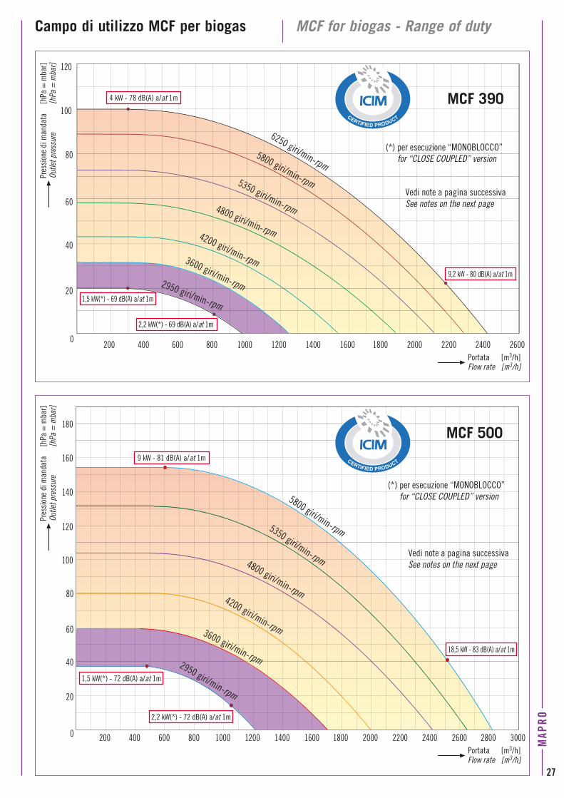
Campo di utilizzo MCF per biogas MCF for biogas - Range of duty
200 6004000 800 12001000 1400 18001600 2000 24002200 2600 2800 3000
20
40
60
80
100
120
140
160
180MCF 500
200 6004000
800 12001000 1400 18001600 2000 24002200 2600
20
40
60
80
100
120
MCF 390
Portata [m3/h] Flow rate [m3/h]
6250 giri/min-rpm
(*) per esecuzione “MONOBLOCCO” for “CLOSE COUPLED” version
Vedi note a pagina successiva See notes on the next page
(*) per esecuzione “MONOBLOCCO” for “CLOSE COUPLED” version
4 kW - 78 dB(A) a/at 1m
9 kW - 81 dB(A) a/at 1m
1,5 kW(*) - 69 dB(A) a/at 1m
1,5 kW(*) - 72 dB(A) a/at 1m
2,2 kW(*) - 69 dB(A) a/at 1m
2,2 kW(*) - 72 dB(A) a/at 1m
5800 giri/min-rpm5350 giri/min-rpm4800 giri/min-rpm4200 giri/min-rpm3600 giri/min-rpm2950 giri/min-rpm
9,2 kW - 80 dB(A) a/at 1m
18,5 kW - 83 dB(A) a/at 1m
5800 giri/min-rpm5350 giri/min-rpm4800 giri/min-rpm4200 giri/min-rpm3600 giri/min-rpm2950 giri/min-rpm
Pres
sion
e di
man
data
[h
Pa =
mba
r]Ou
tlet p
ress
ure
[hPa
= m
bar]
Pres
sion
e di
man
data
[h
Pa =
mba
r]Ou
tlet p
ress
ure
[hPa
= m
bar]
Portata [m3/h] Flow rate [m3/h]
Vedi note a pagina successiva See notes on the next page
MAP
RO
27
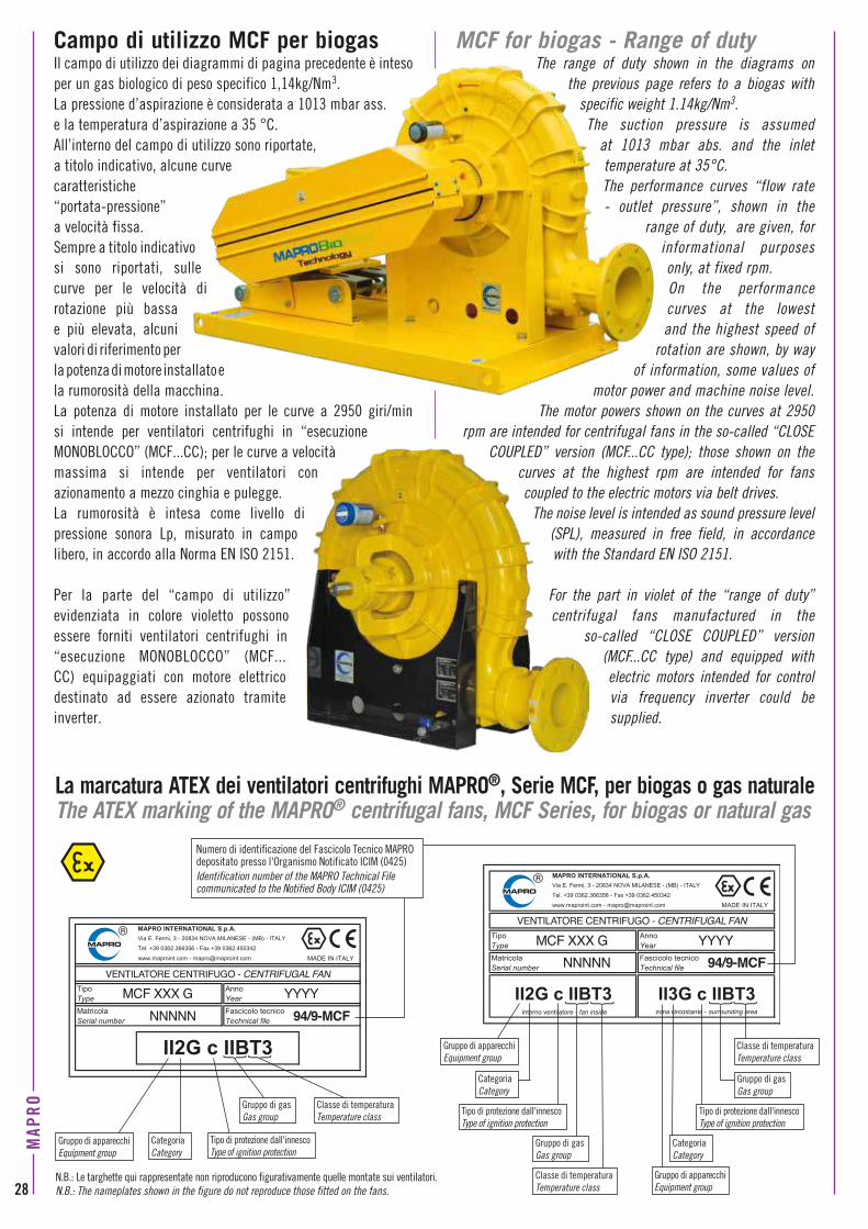
Campo di utilizzo MCF per biogasIl campo di utilizzo dei diagrammi di pagina precedente è inteso per un gas biologico di peso specifico 1,14kg/Nm3. La pressione d’aspirazione è considerata a 1013 mbar ass. e la temperatura d’aspirazione a 35 °C. All’interno del campo di utilizzo sono riportate, a titolo indicativo, alcune curve caratteristiche “portata-pressione” a velocità fissa. Sempre a titolo indicativo si sono riportati, sulle curve per le velocità di rotazione più bassa e più elevata, alcuni valori di riferimento per la potenza di motore installato e la rumorosità della macchina. La potenza di motore installato per le curve a 2950 giri/min si intende per ventilatori centrifughi in “esecuzione MONOBLOCCO” (MCF...CC); per le curve a velocità massima si intende per ventilatori con azionamento a mezzo cinghia e pulegge. La rumorosità è intesa come livello di pressione sonora Lp, misurato in campo libero, in accordo alla Norma EN ISO 2151.
Per la parte del “campo di utilizzo” evidenziata in colore violetto possono essere forniti ventilatori centrifughi in “esecuzione MONOBLOCCO” (MCF...CC) equipaggiati con motore elettrico destinato ad essere azionato tramite inverter.
MCF for biogas - Range of dutyThe range of duty shown in the diagrams on
the previous page refers to a biogas with specific weight 1.14kg/Nm3.
The suction pressure is assumed at 1013 mbar abs. and the inlet temperature at 35°C. The performance curves “flow rate - outlet pressure”, shown in the
range of duty, are given, for informational purposes only, at fixed rpm. On the performance curves at the lowest and the highest speed of
rotation are shown, by way of information, some values of
motor power and machine noise level.The motor powers shown on the curves at 2950
rpm are intended for centrifugal fans in the so-called “CLOSE COUPLED” version (MCF...CC type); those shown on the
curves at the highest rpm are intended for fans coupled to the electric motors via belt drives.
The noise level is intended as sound pressure level (SPL), measured in free field, in accordance with the Standard EN ISO 2151.
For the part in violet of the “range of duty” centrifugal fans manufactured in the
so-called “CLOSE COUPLED” version (MCF...CC type) and equipped with electric motors intended for control via frequency inverter could be supplied.
VENTILATORE CENTRIFUGO - CENTRIFUGAL FAN
MCF XXX GNNNNN 94/9-MCF
YYYY
VENTILATORE CENTRIFUGO - CENTRIFUGAL FAN
MCF XXX GNNNNN 94/9-MCF
YYYY
interno ventilatore - fan inside zona circostante - surrounding area
CategoriaCategory
CategoriaCategory
Gruppo di apparecchiEquipment group
Gruppo di apparecchiEquipment group
Gruppo di apparecchiEquipment group
Tipo di protezione dall'innescoType of ignition protection
Tipo di protezione dall'innescoType of ignition protection
Tipo di protezione dall'innescoType of ignition protection
Gruppo di gasGas group
Gruppo di gasGas group
Classe di temperaturaTemperature class
Classe di temperaturaTemperature class
Classe di temperaturaTemperature class
Numero di identificazione del Fascicolo Tecnico MAPRO depositato presso l'Organismo Notificato ICIM (0425)Identification number of the MAPRO Technical File communicated to the Notified Body ICIM (0425)
CategoriaCategory
Gruppo di gasGas group
La marcatura ATEX dei ventilatori centrifughi MAPRO®, Serie MCF, per biogas o gas naturaleThe ATEX marking of the MAPRO® centrifugal fans, MCF Series, for biogas or natural gas
N.B.: Le targhette qui rappresentate non riproducono figurativamente quelle montate sui ventilatori. N.B.: The nameplates shown in the figure do not reproduce those fitted on the fans.28
MAP
RO
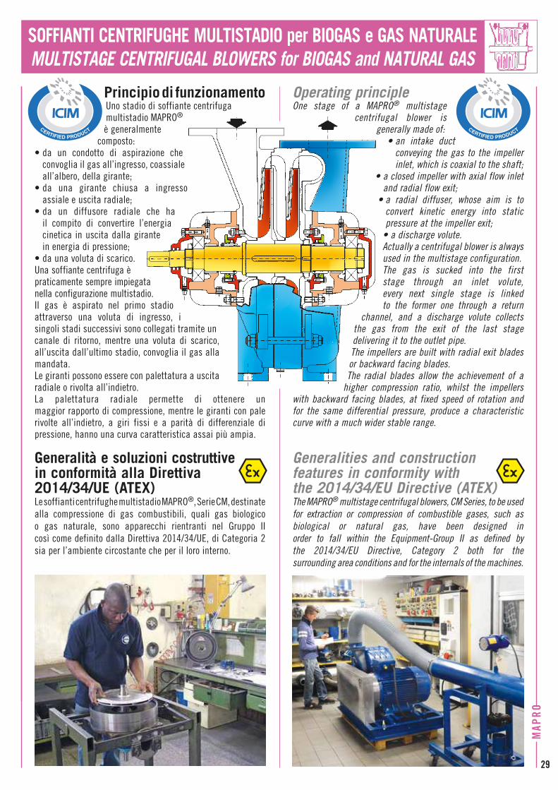
SOFFIANTI CENTRIFUGHE MULTISTADIO per BIOGAS e GAS NATURALEMULTISTAGE CENTRIFUGAL BLOWERS for BIOGAS and NATURAL GAS
Principio di funzionamento Uno stadio di soffiante centrifuga multistadio MAPRO® è generalmente
composto:• da un condotto di aspirazione che
convoglia il gas all’ingresso, coassiale all’albero, della girante;
• da una girante chiusa a ingresso assiale e uscita radiale;
• da un diffusore radiale che ha il compito di convertire l’energia cinetica in uscita dalla girante in energia di pressione;
• da una voluta di scarico.Una soffiante centrifuga è praticamente sempre impiegata nella configurazione multistadio. Il gas è aspirato nel primo stadio attraverso una voluta di ingresso, i singoli stadi successivi sono collegati tramite un canale di ritorno, mentre una voluta di scarico, all’uscita dall’ultimo stadio, convoglia il gas alla mandata. Le giranti possono essere con palettatura a uscita radiale o rivolta all’indietro. La palettatura radiale permette di ottenere un maggior rapporto di compressione, mentre le giranti con pale rivolte all’indietro, a giri fissi e a parità di differenziale di pressione, hanno una curva caratteristica assai più ampia.
Generalità e soluzioni costruttive in conformità alla Direttiva 2014/34/UE (ATEX)Le soffianti centrifughe multistadio MAPRO®, Serie CM, destinate alla compressione di gas combustibili, quali gas biologico o gas naturale, sono apparecchi rientranti nel Gruppo II così come definito dalla Direttiva 2014/34/UE, di Categoria 2 sia per l’ambiente circostante che per il loro interno.
Operating principle One stage of a MAPRO® multistage
centrifugal blower is generally made of:
• an intake duct conveying the gas to the impeller inlet, which is coaxial to the shaft;
• a closed impeller with axial flow inlet and radial flow exit;
• a radial diffuser, whose aim is to convert kinetic energy into static pressure at the impeller exit;
• a discharge volute.Actually a centrifugal blower is always used in the multistage configuration. The gas is sucked into the first stage through an inlet volute, every next single stage is linked to the former one through a return
channel, and a discharge volute collects the gas from the exit of the last stage delivering it to the outlet pipe.The impellers are built with radial exit blades or backward facing blades. The radial blades allow the achievement of a
higher compression ratio, whilst the impellers with backward facing blades, at fixed speed of rotation and for the same differential pressure, produce a characteristic curve with a much wider stable range.
Generalities and construction features in conformity with the 2014/34/EU Directive (ATEX)The MAPRO® multistage centrifugal blowers, CM Series, to be used for extraction or compression of combustible gases, such as biological or natural gas, have been designed in order to fall within the Equipment-Group II as defined by the 2014/34/EU Directive, Category 2 both for the surrounding area conditions and for the internals of the machines.
MAP
RO
29
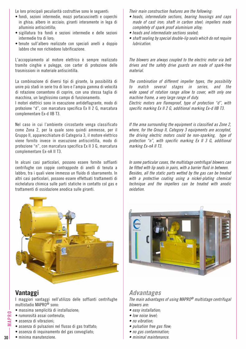
Le loro principali peculiarità costruttive sono le seguenti:• fondi, sezioni intermedie, mozzi portacuscinetti e coperchi
in ghisa; albero in acciaio; giranti interamente in lega di alluminio antiscintilla;
• sigillatura tra fondi e sezioni intermedie e delle sezioni intermedie tra di loro;
• tenute sull’albero realizzate con speciali anelli a doppio labbro che non richiedono lubrificazione.
L’accoppiamento al motore elettrico è sempre realizzato tramite cinghie e pulegge, con carter di protezione delle trasmissioni in materiale antiscintilla.
La combinazione di diversi tipi di girante, la possibilità di unire più stadi in serie tra di loro e l’ampia gamma di velocità di rotazione consentono di coprire, con una stessa taglia di macchina, un larghissimo campo di funzionamento.I motori elettrici sono in esecuzione antideflagrante, modo di protezione “d”, con marcatura specifica Ex II 2 G, marcatura complementare Ex-d IIB T3.
Nel caso in cui l’ambiente circostante venga classificato come Zona 2, per la quale sono quindi ammesse, per il Gruppo II, apparecchiature di Categoria 3, il motore elettrico viene fornito invece in esecuzione antiscintilla, modo di protezione “n”, con marcatura specifica Ex II 3 G, marcatura complementare Ex-nA II T3.
In alcuni casi particolari, possono essere fornite soffianti centrifughe con coppie contrapposte di anelli di tenuta a labbro, tra i quali viene immesso un fluido di sbarramento. In altri casi particolari, possono essere effettuati trattamenti di nichelatura chimica sulle parti statiche in contatto col gas e trattamenti di ossidazione anodica sulle giranti.
VantaggiI maggiori vantaggi nell’utilizzo delle soffianti centrifughe multistadio MAPRO® sono:• massima semplicità di installazione;• rumorosità assai contenuta;• assenza di vibrazioni;• assenza di pulsazioni nel flusso di gas trattato; • assenza di inquinamento del gas convogliato;• minima manutenzione.
Their main construction features are the following:• heads, intermediate sections, bearing housings and caps
made of cast iron; shaft in carbon steel; impellers made completely of spark proof aluminium alloy;
• heads and intermediate sections sealed;• shaft sealing by special double-lip seals which do not require
lubrication.
The blowers are always coupled to the electric motor via belt drives and the safety drive guards are made of spark-free material.
The combination of different impeller types, the possibility to match several stages in series, and the wide speed of rotation range allow to cover, with only one machine frame, a very large range of duty.Electric motors are flameproof, type of protection “d”, with specific marking Ex II 2 G, additional marking Ex-d IIB T3.
If the area surrounding the equipment is classified as Zone 2, where, for the Group II, Category 3 equipments are accepted, the driving electric motors could be non-sparking, type of protection “n”, with specific marking Ex II 3 G, additional marking Ex-nA II T3.
In some particular cases, the multistage centrifugal blowers can be fitted with lip seals in pairs, with a barrier fluid in between. Besides, all the static parts wetted by the gas can be treated with a protective coating using a nickel-plating chemical technique and the impellers can be treated with anodic oxidation.
AdvantagesThe main advantages of using MAPRO® multistage centrifugal blowers are:• easy installation;• low noise level;• no vibration;• pulsation free gas flow; • no gas contamination; • minimal maintenance.30
MAP
RO
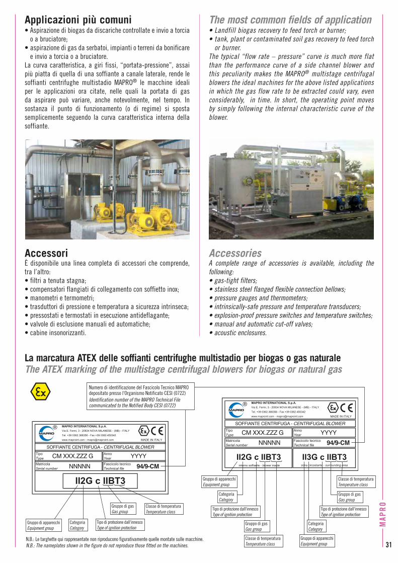
AccessoriÈ disponibile una linea completa di accessori che comprende, tra l’altro:• filtri a tenuta stagna;• compensatori flangiati di collegamento con soffietto inox;• manometri e termometri;• trasduttori di pressione e temperatura a sicurezza intrinseca;• pressostati e termostati in esecuzione antideflagante;• valvole di esclusione manuali ed automatiche;• cabine insonorizzanti.
AccessoriesA complete range of accessories is available, including the following:• gas-tight filters;• stainless steel flanged flexible connection bellows;• pressure gauges and thermometers;• intrinsically-safe pressure and temperature transducers;• explosion-proof pressure switches and temperature switches;• manual and automatic cut-off valves;• acoustic enclosures.
La marcatura ATEX delle soffianti centrifughe multistadio per biogas o gas naturaleThe ATEX marking of the multistage centrifugal blowers for biogas or natural gas
SOFFIANTE CENTRIFUGA - CENTRIFUGAL BLOWER
CM XXX.ZZZ GNNNNN 94/9-CM
YYYY
SOFFIANTE CENTRIFUGA - CENTRIFUGAL BLOWER
CM XXX.ZZZ GNNNNN 94/9-CM
YYYY
interno soffiante - blower inside zona circostante - surrounding area
CategoriaCategory
CategoriaCategory
Gruppo di apparecchiEquipment group
Gruppo di apparecchiEquipment group
Gruppo di apparecchiEquipment group
Tipo di protezione dall'innescoType of ignition protection
Tipo di protezione dall'innescoType of ignition protection
Tipo di protezione dall'innescoType of ignition protection
Gruppo di gasGas group
Gruppo di gasGas group
Classe di temperaturaTemperature class
Classe di temperaturaTemperature class
Classe di temperaturaTemperature class
Numero di identificazione del Fascicolo Tecnico MAPRO depositato presso l'Organismo Notificato CESI (0722)Identification number of the MAPRO Technical File communicated to the Notified Body CESI (0722)
CategoriaCategory
Gruppo di gasGas group
N.B.: Le targhette qui rappresentate non riproducono figurativamente quelle montate sulle macchine. N.B.: The nameplates shown in the figure do not reproduce those fitted on the machines.
Applicazioni più comuni • Aspirazione di biogas da discariche controllate e invio a torcia
o a bruciatore;• aspirazione di gas da serbatoi, impianti o terreni da bonificare
e invio a torcia o a bruciatore.La curva caratteristica, a giri fissi, “portata-pressione”, assai più piatta di quella di una soffiante a canale laterale, rende le soffianti centrifughe multistadio MAPRO® le macchine ideali per le applicazioni ora citate, nelle quali la portata di gas da aspirare può variare, anche notevolmente, nel tempo. In sostanza il punto di funzionamento (o di regime) si sposta semplicemente seguendo la curva caratteristica interna della soffiante.
The most common fields of application • Landfill biogas recovery to feed torch or burner;• tank, plant or contaminated soil gas recovery to feed torch
or burner.The typical “flow rate – pressure” curve is much more flat than the performance curve of a side channel blower and this peculiarity makes the MAPRO® multistage centrifugal blowers the ideal machines for the above listed applications in which the gas flow rate to be extracted could vary, even considerably, in time. In short, the operating point moves by simply following the internal characteristic curve of the blower.
MAP
RO
31
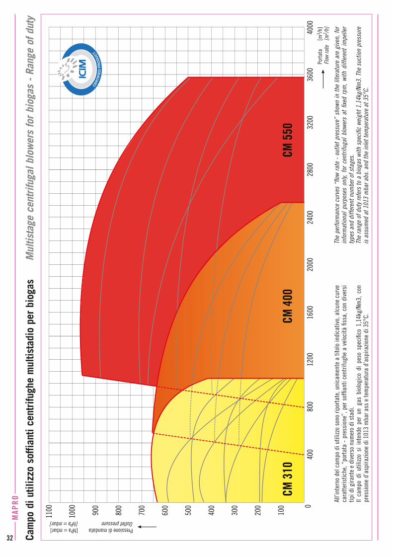
Cam
po d
i util
izzo
sof
fiant
i cen
trifu
ghe
mul
tista
dio
per
biog
as
M
ultis
tage
cen
trifu
gal b
low
ers
for b
ioga
s - R
ange
of d
uty
Pressione di mandata [hPa = mbar]Outlet pressure [hPa = mbar]
Porta
ta
[m3 /h
]Flo
w ra
te
[m3 /h
]
All’i
nter
no d
el c
ampo
di u
tilizz
o so
no ri
porta
te, u
nica
men
te a
tito
lo in
dica
tivo,
alc
une
curv
e ca
ratte
ristic
he, “
porta
ta -
pre
ssio
ne”,
per
sof
fiant
i cen
trifu
ghe
a ve
loci
tà fi
ssa,
con
div
ersi
tip
i di g
irant
e e
dive
rso
num
ero
di s
tadi
. Il
cam
po d
i ut
ilizz
o si
int
ende
per
un
gas
biol
ogic
o di
pes
o sp
ecifi
co 1
,14k
g/Nm
3, c
on
pres
sion
e d’
aspi
razio
ne d
i 101
3 m
bar a
ss e
tem
pera
tura
d’a
spira
zione
di 3
5°C.
The
perfo
rman
ce c
urve
s “fl
ow ra
te -
out
let p
ress
ure”
sho
wn in
the
liter
atur
e ar
e gi
ven,
for
info
rmat
iona
l pur
pose
s on
ly, f
or c
entri
fuga
l blo
wers
at
fixed
rpm
, with
diff
eren
t im
pelle
r ty
pes
and
diffe
rent
num
ber o
f sta
ges.
Th
e ra
nge
of d
uty r
efer
s to
a b
ioga
s wi
th s
peci
fic w
eigh
t 1.1
4kg/
Nm3.
The
suc
tion
pres
sure
is
ass
umed
at 1
013
mba
r abs
. and
the
inle
t tem
pera
ture
at 3
5°C.
0
100
200
300
400
500
600
700
800
900
1000
1100
1600
800
3200
2800
400
2400
1200
2000
4000
3600
CM 3
10CM
400
CM 5
50
32
MAP
RO

DimensioniDi seguito vengono riportate, a titolo indicativo, le dimensioni delle soffianti centrifughe multistadio CM 310, CM 400 e CM 550 per biogas o gas naturale.Le macchine si intendono equipaggiate con motore elettrico, sempre a due poli, in esecuzione antideflagrante, modo di protezione “d”, con marcatura specifica Ex II 2 G, marcatura complementare Ex-d IIB T3, e i pesi, dati anch'essi a titolo indicativo, comprendono il motore di maggiore potenza tra quelli previsti per lo specifico tipo di soffiante.
Il numero che segue “CM 310.” nella sigla della macchina, rappresenta il numero di stadi che compongono la soffiante centrifuga. Ad esempio, la sigla CM 310.5 indica che la soffiante è composta da 5 stadi in serie tra di loro.
Le soffianti possono essere anche fornite con voluta di scarico ruotata di 90° in modo che la flangia di mandata sia orientata verso l’alto come quella di aspirazione (vedi foto di un CM 400 a pagina successiva).
The number following “CM 310.” in the “Machine type” column, represents the number of stages the centrifugal blower consists of.For instance, CM 310.5 specifies that the blower consists of 5 stages in series.The blowers could also be supplied with the discharge volute turned through 90°, so that the outlet flange is facing upwards as the inlet flange (see picture of a CM 400 on the next page).
DimensionsBelow and on the next two pages you can find, for informational purposes only, the dimensions of the CM 310, CM 400 and CM 550 multistage centrifugal blowers for biogas or natural gas. The blowers are always equipped with two pole motors.The weights, given as well for informational purposes only, are for blowers equipped with type of protection “d” flameproof electric motor, with specific marking Ex II 2 G, additional marking Ex-d IIB T3, and they include the weight of the motor of highest power rating amongst those listed for the specific blower.
Dimensioni [mm] - Dimensions [mm]
Tipo macchinaMachine type
Potenze motoriMotor powers
[kW]A B C D E ØF I L M N O P Q R
ASPIRAZIONEINLET
MANDATAOUTLET
PesoWeight
[kg]EN 1092-1 EN 1092-1
CM 310.2 3 ÷ 5,5 953 600 600 233 181 12 165 900 860 600 660 53 720 - PN16 DN80 PN16 DN80 235
CM 310.3 4 ÷ 7,5 953 700 600 233 237 12 165 900 860 700 660 53 720 - PN16 DN80 PN16 DN80 270
CM 310.4 5,5 ÷ 15 953 700 600 233 292 12 165 900 860 700 660 53 720 - PN16 DN80 PN16 DN80 340
CM 310.5 7,5 ÷ 18,5 953 700 600 233 348 12 165 900 860 700 660 53 720 - PN16 DN80 PN16 DN80 375
CM 310.67,5 ÷ 15 953 735 600 233 403 12 165 900 860 700 660 53 720 35 PN16 DN80 PN16 DN80 380
18,5 ÷ 22 1153 900 640 233 403 12 205 1100 1050 900 850 53 920 - PN16 DN80 PN16 DN80 450
CM 310.7 11 ÷ 30 1153 900 640 233 459 12 205 1100 1050 900 850 53 920 - PN16 DN80 PN16 DN80 505
CM 310.8 11 ÷ 37 1153 900 640 233 514 12 205 1100 1050 900 850 53 920 - PN16 DN80 PN16 DN80 550
CM 310.9 11 ÷ 37 1153 900 640 233 569 12 205 1100 1050 900 850 53 920 - PN16 DN80 PN16 DN80 570
4xØFP
I
ALM
Q
C
BNO
R
E D
CM 310
MAP
RO
33
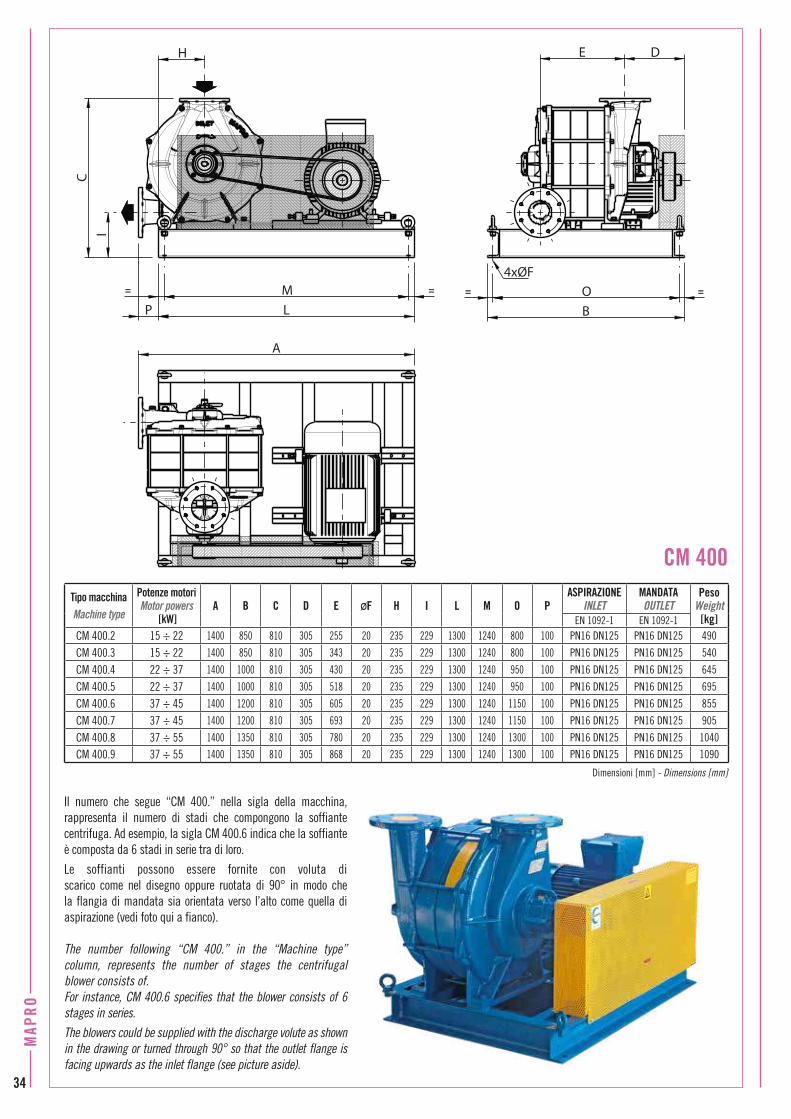
Il numero che segue “CM 400.” nella sigla della macchina, rappresenta il numero di stadi che compongono la soffiante centrifuga. Ad esempio, la sigla CM 400.6 indica che la soffiante è composta da 6 stadi in serie tra di loro.
Le soffianti possono essere fornite con voluta di scarico come nel disegno oppure ruotata di 90° in modo che la flangia di mandata sia orientata verso l’alto come quella di aspirazione (vedi foto qui a fianco).
The number following “CM 400.” in the “Machine type” column, represents the number of stages the centrifugal blower consists of.For instance, CM 400.6 specifies that the blower consists of 6 stages in series.The blowers could be supplied with the discharge volute as shown in the drawing or turned through 90° so that the outlet flange is facing upwards as the inlet flange (see picture aside).
Dimensioni [mm] - Dimensions [mm]
Tipo macchinaMachine type
Potenze motoriMotor powers
[kW]A B C D E ØF H I L M O P
ASPIRAZIONEINLET
MANDATAOUTLET
PesoWeight
[kg]EN 1092-1 EN 1092-1
CM 400.2 15 ÷ 22 1400 850 810 305 255 20 235 229 1300 1240 800 100 PN16 DN125 PN16 DN125 490
CM 400.3 15 ÷ 22 1400 850 810 305 343 20 235 229 1300 1240 800 100 PN16 DN125 PN16 DN125 540
CM 400.4 22 ÷ 37 1400 1000 810 305 430 20 235 229 1300 1240 950 100 PN16 DN125 PN16 DN125 645
CM 400.5 22 ÷ 37 1400 1000 810 305 518 20 235 229 1300 1240 950 100 PN16 DN125 PN16 DN125 695
CM 400.6 37 ÷ 45 1400 1200 810 305 605 20 235 229 1300 1240 1150 100 PN16 DN125 PN16 DN125 855
CM 400.7 37 ÷ 45 1400 1200 810 305 693 20 235 229 1300 1240 1150 100 PN16 DN125 PN16 DN125 905
CM 400.8 37 ÷ 55 1400 1350 810 305 780 20 235 229 1300 1240 1300 100 PN16 DN125 PN16 DN125 1040
CM 400.9 37 ÷ 55 1400 1350 810 305 868 20 235 229 1300 1240 1300 100 PN16 DN125 PN16 DN125 1090
IC
P= M =
LO= =
B
DE
A
H
4xØF
CM 400
34
MAP
RO
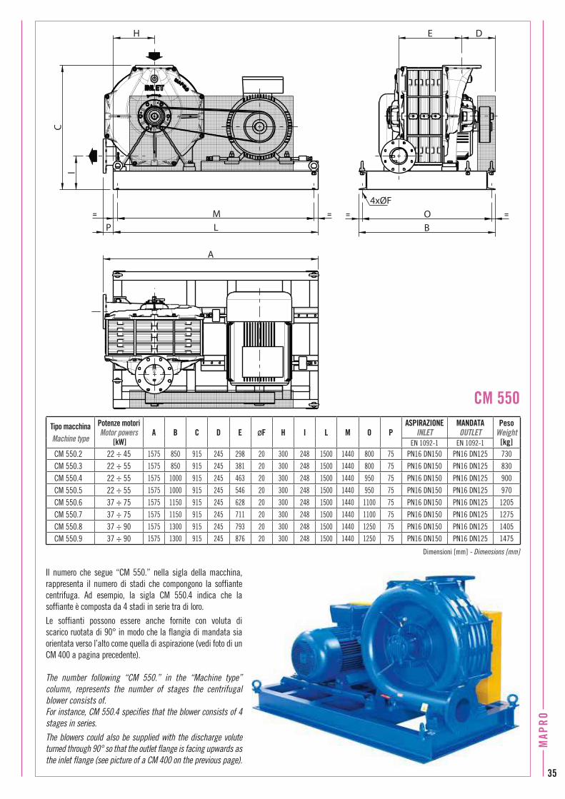
Il numero che segue “CM 550.” nella sigla della macchina, rappresenta il numero di stadi che compongono la soffiante centrifuga. Ad esempio, la sigla CM 550.4 indica che la soffiante è composta da 4 stadi in serie tra di loro.
Le soffianti possono essere anche fornite con voluta di scarico ruotata di 90° in modo che la flangia di mandata sia orientata verso l’alto come quella di aspirazione (vedi foto di un CM 400 a pagina precedente).
The number following “CM 550.” in the “Machine type” column, represents the number of stages the centrifugal blower consists of.For instance, CM 550.4 specifies that the blower consists of 4 stages in series.The blowers could also be supplied with the discharge volute turned through 90° so that the outlet flange is facing upwards as the inlet flange (see picture of a CM 400 on the previous page).
Dimensioni [mm] - Dimensions [mm]
Tipo macchinaMachine type
Potenze motoriMotor powers
[kW]A B C D E ØF H I L M O P
ASPIRAZIONEINLET
MANDATAOUTLET
PesoWeight
[kg]EN 1092-1 EN 1092-1
CM 550.2 22 ÷ 45 1575 850 915 245 298 20 300 248 1500 1440 800 75 PN16 DN150 PN16 DN125 730
CM 550.3 22 ÷ 55 1575 850 915 245 381 20 300 248 1500 1440 800 75 PN16 DN150 PN16 DN125 830
CM 550.4 22 ÷ 55 1575 1000 915 245 463 20 300 248 1500 1440 950 75 PN16 DN150 PN16 DN125 900
CM 550.5 22 ÷ 55 1575 1000 915 245 546 20 300 248 1500 1440 950 75 PN16 DN150 PN16 DN125 970
CM 550.6 37 ÷ 75 1575 1150 915 245 628 20 300 248 1500 1440 1100 75 PN16 DN150 PN16 DN125 1205
CM 550.7 37 ÷ 75 1575 1150 915 245 711 20 300 248 1500 1440 1100 75 PN16 DN150 PN16 DN125 1275
CM 550.8 37 ÷ 90 1575 1300 915 245 793 20 300 248 1500 1440 1250 75 PN16 DN150 PN16 DN125 1405
CM 550.9 37 ÷ 90 1575 1300 915 245 876 20 300 248 1500 1440 1250 75 PN16 DN150 PN16 DN125 1475
4xØF
DE
O ==
BP LM= =
H
CI
A
CM 550
MAP
RO
35

COMPRESSORI ROTATIVI a PALETTE per BIOGAS e GAS NATURALESLIDING VANE ROTARY COMPRESSORS for BIOGAS and NATURAL GASPrincipio di funzionamento Un rotore cilindrico gira eccentrico in uno statore anch’esso cilindrico di diametro più grande: tra i due rimane uno spazio libero a forma di mezzaluna.Il rotore ha delle cave nelle quali scorrono liberamente lamelle in materiale plastico stratificato; queste, quando il rotore gira, aderiscono per forza centrifuga alla superficie interna dello statore, formando dei vani il cui volume passa, con la rotazione, da un massimo ad un minimo.L’aspirazione avviene attraverso delle luci aperte nello statore nella zona dei volumi crescenti; la mandata avviene attraverso delle luci aperte nello statore, nella zona dei volumi decrescenti.
Operating principle A cylindrical rotor turns eccentrically in a cylindrical stator of a larger diameter: the free space left between stator and rotor is half-moon shaped.Some slots are milled in the rotor and stratified plastic blades slide freely into the slots. The blades, as the rotor turns, are forced out against the cylindrical wall of the stator by centrifugal force, so creating individual cells whose volume reduces from a maximum to a minimum during the rotation.The suction takes place through ports in the stator in the area of increasing volumes; the discharge through ports in the area of decreasing volumes.
Generalities and construction features in conformity with the 2014/34/EU Directive (ATEX)The MAPRO® sliding vane rotary compressors to be used for compression of combustible gases, such as biological or natural gas, have been designed in order to fall within the Equipment-Group II as defined by the 2014/34/EU Directive, Category 2 both for the surrounding area conditions and for the internals of the machines. Their main construction features are the following:• casing (stator and heads) in cast iron, rotor in carbon steel,
blades in light stratified spark-free material;• sealing between stator, heads and covers by gaskets and/or
O-rings;• simple or double mechanical seal, depending on the operating
discharge pressure; for the double mechanical seal, the compressor-own oil lubricating system is used as a barrier fluid;
• flexible coupling, with no metal-to-metal contact between driving and driven parts in case of failure of the coupling pins; safety drive guard made of spark-proof metal;
• type of protection “d” flameproof electric motors, with specific marking Ex II 2 G, additional marking Ex-d IIB T3.
Generalità e soluzioni costruttive in conformità alla Direttiva 2014/34/UE (ATEX)I compressori rotativi a palette MAPRO® destinati alla compres-sione di gas combustibili, quali gas biologico o gas naturale, sono apparecchi rientranti nel Gruppo II così come definito dalla Direttiva 2014/34/UE, di Categoria 2 sia per l’ambiente circostante che per il loro interno. Le loro principali peculiarità costruttive sono le seguenti:• carcassa (statore e fondi) in ghisa, rotore in acciaio, palette in
laminato plastico stratificato antiscintilla;• sigillatura tra statore, fondi e coperchi costituenti il corpo
macchina tramite guarnizioni piane e/o anelli torici;• tenuta meccanica sull’albero, semplice o doppia, in funzione
della pressione di esercizio; nel caso di doppia tenuta, si utilizza come fluido “barriera” lo stesso olio destinato alla lubrificazione del compressore;
• giunto d’accoppiamento nel quale, in caso di rottura dei tamponi elastici, le parti motrice e condotta non entrano in contatto; carter di protezione della trasmissione in materiale antiscintilla;
• motori elettrici in esecuzione antideflagrante, modo di protezione “d”, con marcatura specifica Ex II 2 G, marcatura complementare minima Ex-d IIB T3.36
MAP
RO

Nel caso in cui l’ambiente circostante venga classificato come Zona 2, per la quale sono quindi ammesse, per il Gruppo II, apparecchiature di Categoria 3, il motore elettrico del compressore potrà essere antiscintilla, modo di protezione “n”, con marcatura specifica Ex II 3 G, marcatura complementare Ex-nA II T3.Il corpo compressore vero e proprio può essere proposto con raffreddamento tramite aria ambiente che, aspirata da un ventilatore assiale montato sul giunto d’accoppiamento al motore, viene convogliata tra la superficie esterna alettata dello statore e un carter di convogliamento avvolgente il corpo macchina stesso; oppure, con raffreddamento tramite circolazione di acqua nella camicia avvolgente il corpo.Il calore si trasferisce dal metallo all'acqua più efficacemente che non dal metallo all'aria. La riduzione di temperatura del gas compresso è quindi maggiore nei compressori raffreddati ad acqua.Essi possono dunque comprimere il gas a pressioni più elevate e coprono una gamma di portate aspirate notevolmente superiore a quella dei compressori raffreddati ad aria.
If the area surrounding the equipment is classified as Zone 2, where, for the Group II, Category 3 equipments are accepted, the machine could be equipped with the type of protection “n” non-sparking motor, with specific marking Ex II 3 G, additional marking Ex-nA II T3.The compressor body in itself could be air-cooled or water-cooled. In the air-cooled compressors, ambient air is blown by an axial fan, fitted on the flexible coupling between machine and motor, around the finned cylinder and heads to provide cooling. The air is forced between the outer finned surface of the stator and an air conveying guard surrounding the compressor itself.In water-cooled compressors, an integral water jacket surrounds the cylinder and heads. Heat transfers through the metal to the water more effectively than through metal to air. Thus, water-cooled compressors reduce the internal temperature of the compressed gas more efficiently than air-cooled units. They can therefore compress the gas to a higher pressure than air-cooled units. Moreover the water-cooled compressors are capable of handling flow rates that cover a well larger range than the air-cooled compressors.
MAP
RO
37

VantaggiI maggiori vantaggi nell’utilizzo dei compressori rotativi a palette MAPRO® per la compressione di gas biologico o gas naturale sono:
• Rendimenti elevati ed invariabiliIl compressore a palette MAPRO® è di tipo volumetrico. La compressione avviene cioè per progressiva riduzione, durante la rotazione, del “volume” di gas trasferito dalla bocca di aspirazione a quella di mandata. Le luci di mandata vengono aperte nello statore, di volta in volta, ad un’altezza determinata dalla pressione di esercizio prevista, in modo da utilizzare solo la potenza necessaria per l’effettiva “compressione” del gas. Ne risulta un rendimento di compressione adiabatica sempre elevato e, in generale, compreso tra il 70% e l’80% se riferito alla cilindrata del compressore. I ristretti giochi interni consentono un rendimento volumetrico anch’esso elevato e praticamente invariabile in quanto l’usura nel tempo delle lamelle si compensa automaticamente.La potenza necessaria per la compressione risulta quindi, in generale, inferiore a quella richiesta da altri tipi di compressori, con conseguente economicità di gestione.
• Manutenzione semplice ed economicaIl numero ridotto di parti in movimento semplifica le operazioni di smontaggio e rimontaggio rendendole quindi molto più economiche rispetto ad altri tipi di compressori volumetrici. Un rapido sistema di misura dall’esterno permette di valutare, a intervalli di tempo prestabiliti, lo stato di usura delle lamelle senza dover smontare, neppure parzialmente, il corpo macchina per accedere alla camera di compressione.La sostituzione delle lamelle può quindi essere programmata in anticipo, in funzione delle esigenze di lavoro dell’impianto o delle necessità di manutenzione di altre parti, semplificando la gestione dell’impianto stesso e migliorandone l’economicità.
AdvantagesThe main advantages of using MAPRO® sliding vane rotary compressors for compressing biogas or natural gas are:
• Unchangeable and high efficiency MAPRO® rotary vane compressors are positive-displacement machines. That is, the compression takes place for progressive reduction, inside the machine body, during rotation, of the gas “volume” mechanically displaced from the suction to the discharge port. The discharge port is opened, on the internal cylindrical surface of the stator, at an height depending on the foreseen discharge pressure, so that only the power needed for the actual “compression” of the gas is used. It follows that the adiabatic compression efficiency is always high, and, in general, between the 70% and the 80% if referred to the compressor displacement.
The tight internal clearances allow, as well, a high volumetric efficiency, basically unchangeable as blades wear is self-compensating in time. The power needed for the compression is therefore, in
general, lower than that required from other types of compressors, with consequent lower operating costs.
• Simple and economic maintenance The small number of parts in motion simplifies the compressor disassembly and reassembly, so making these operations well less expensive than compared to other types of positive displacement machines. A specially provided control rod allows a quick evaluation, at fixed time intervals, of the blades wear, without disassembling, even partially, the machine body.
It is therefore possible to plan the blades replacement largely in advance, according to the working planning of the plant or to the maintenance needs of other equipments, so simplifying the plant operation and improving its efficiency and economy.
38
MAP
RO

• Flusso di gas continuo e senza pulsazioni Il flusso di gas è continuo (non pulsante) sia in aspirazione che in mandata, rendendo quindi non necessari serbatoi di accumulo o smorzatori. I compressori rotativi a palette MAPRO® sono macchine compatte, nelle quali il leggero squilibrio dovuto alla diversa posizione radiale delle lamelle rispetto all’asse di rotazione, non genera vibrazioni apprezzabili durante la marcia, e non rende quindi necessarie particolari fondazioni. Già di principio meno rumorosi di altri tipi di compressori, ove richiesto, possono essere insonorizzati.
• Protezione interna nella compressione di biogasL’olio utilizzato per scopi strettamente meccanici, e cioè per la lubrificazione di cuscinetti, lamelle, tenuta meccanica, segmenti, svolge anche altri due ruoli importanti nei compressori per gas biologico. La sottile pellicola di lubrificante, continuamente rinnovata, protegge innanzitutto le superfici interne dagli acidi contenuti nel biogas e tende inoltre a inglobare le impurità in esso presenti sotto forma di particelle solide o liquide, svolgendo così anche un’azione di pulizia interna della camera di compressione.La “lubrificazione con olio a perdere” rende quindi il rotativo a palette MAPRO® un compressore, pur se realizzato con materiali ordinari come ghisa e acciaio al carbonio, particolarmente adatto a trattare gas potenzialmente corrosivi, contenenti impurità e saturi in vapor d’acqua, caratteristiche tutte proprie del gas biologico.
Applicazioni più comuni • Ricircolo di gas biologico nei digestori anaerobici per la
miscelazione dei fanghi;• aspirazione di biogas da gasometro, discarica controllata o
altro e invio a stoccaggio o motore a gas;• aspirazione di gas naturale da rete o da gasometro e invio a
motore a gas.
The most common fields of application • Biogas recirculation into anaerobic digesters for sludge
mixing;• extraction of biogas from gasometer or landfill and delivery to
storage systems or gas engine supply;• extraction of natural gas from pipeline or gasometer, and
delivery to storage systems or gas engine supply.
• Gas flow without pulsations The gas flow is continuous (no pulsation) both at the suction and at the discharge, and so there is no need to install storage tanks or gas dampers.MAPRO® rotary vane compressors are compact machines on which the light unbalance, due to the different radial position of the blades with respect to the axis of rotation, does not cause any significant vibration throughout the running operation. Therefore no special foundations are required. The rotary vane compressors are, in principle, less noisy than other types of compressors. Anyway, when required, they can be supplied complete with acoustic enclosures.
• Internal protection during compression of biogasThe oil used for purely mechanical purposes, that is for the lubrication of bearings, blades, segments, mechanical seals, plays also two important roles in the biogas rotary vane compressors. The thin film of lubricating oil, constantly
renewed, first protects the compressor's internal surfaces from attack of the acids in the biogas; and also tends to incorporate the impurities which are
contained in the biogas in form of solid or liquid particles, with an effect of internal cleaning of the compression chamber.
Therefore, the “oil renewed” lubrication makes MAPRO® rotary vane compressor, even
if made of ordinary materials such as cast iron and carbon steel, particularly suitable for
handling potentially corrosive gases which contain also impurities and moisture saturated. And these are, in general, the biogas peculiarities.
MAP
RO
39

In particular, as regards the supply to gas engines, a gas flow variable in time is required. The rotary vane compressor is a positive-displacement machine and therefore its flow rate, at fixed speed of rotation, is nearly constant. The most effective and economical solution to meet the variable gas demand is to fit a suitable overpressure relief valve on a “by-pass” connecting the discharge pipe back to the suction. When the flow rate required by the gas engine decreases, the compressor discharge pressure increases, and when the set pressure is reached, the overpressure relief valve starts to open and by-passes the excess gas back to the compressor suction.The gas discharged by the compressor has to be, usually, cooled, both for the needs of the engine and to avoid overheating when it is “re-circulated” through the overpressure relief valve.
Tipiche composizioni di fornitura I compressori MAPRO® per gas biologico o gas naturale sono normalmente equipaggiati in funzione dell’uso a cui sono destinati. La componentistica tipica per le applicazioni più comuni, e cioè per i compressori destinati al ricircolo di gas biologico nei digestori anaerobici e per l’alimentazione a motori a gas, è elencata sui diagrammi schematici più avanti illustrati a pag. 43.In particolare, per quanto riguarda l’alimentazione a motori a gas, questi necessitano di una portata variabile nel tempo, in funzione del carico energetico richiesto a valle. Il compressore rotativo a palette è di tipo volumetrico e quindi la sua portata, a giri fissi, è praticamente costante. Per soddisfare la variabilità richiesta, la soluzione più semplice ed economica è quella di installare un’opportuna valvola di sovrappressione lungo una tubazione di “by-pass” che collega, in derivazione, la linea di mandata con quella d’aspirazione.Allorchè la portata di gas richiesta dal motore diminuisce, la pressione alla mandata del compressore tende ad aumentare. Al raggiungimento della pressione di taratura, la valvola di sovrappressione inizia ad aprirsi e a ricircolare la portata di gas in esubero.Il gas in uscita dal compressore deve essere, di solito, raffreddato, sia per le esigenze del motore, sia per evitare surriscaldamenti nelle fasi di ricircolo attraverso la valvola di sovrappressione.
Typical supply components MAPRO® compressors for biogas or natural gas are normally equipped according to the use they are designed for. The typical components for the most common applications, namely for the compressors designed for biogas recirculation into anaerobic digesters for sludge mixing and for the supply to gas engines, are listed on the schematic Piping and Instrumentation Diagrams (P&ID) on page 43.
40
MAP
RO

A questo scopo viene installato, direttamente alla mandata del compressore, un raffreddatore di tipo a fascio tubiero, a grande superficie di scambio e minima perdita di carico, adatto a ridurre la temperatura del gas compresso alla mandata ad un valore anche solo di pochi gradi superiore alla temperatura dell’acqua disponibile.Il raffreddatore, la valvola di sovrappressione e il circuito di “by-pass” sono normalmente dimensionati per il ricircolo dell’intera portata e il compressore può quindi marciare anche se il motore non richiede gas. A valle del raffredatore, e prima del distacco, in derivazione, della linea di “by-pass”, vengono normalmente installati un separatore ciclonico destinato a raccogliere i condensati e, per perfezionare il disoleamento, già parzialmente avvenuto nel separatore ciclonico, uno o più disoliatori a candela ad alta efficienza che riducono i residui di olio nel gas a poche ppm.
Per ridurre il consumo energetico del compressore allorchè il motore a gas richiede una portata ridotta,
è possibile alimentare il motore elettrico del compressore tramite inverter. In generale la
variazione di velocità di rotazione (e quindi di
For this purpose, a gas cooler, generally type stationary tube-sheet, is installed directly at the compressor outlet. This heat exchanger, with its oversized exchange surface
and minimized pressure drop, reduces the temperature of the compressed gas to a value just a few degrees above the temperature of the cooling water.The gas cooler, the overpressure relief valve and the “by-pass” pipe are usually designed for the full
capacity of the machine and thus the compressor can continue to run even if the downstream gas
demand is reduced to zero. Downstream the gas cooler, and before the offtake of the “by-pass” pipe, a cyclonic separator and a final oil separator are normally installed. The cyclonic separator is designed to separate and collect the condensates.
The final oil separator consists of one or more stages of high efficiency coalescing candles which reduce the oil residues in the gas to a few ppm.To reduce the compressors absorbed power when the gas engine demand is reduced, compressors equipped with motors intended for control via frequency inverter can be supplied. In general, the compressor admissible variation in the speed of rotation (and therefore in capacity) is between the 100% and about the 65% of the rated speed.
If the gas engine demand decreases even more, the compressor shall be kept running at
the minimum allowed speed of rotation and the excess flow
rate shall be piped back to compressor inlet through
the overpressure relief valve.
All compressors, equipped as shown on the schematic P&ID on page 43, can be
supplied complete with acoustic enclosure.
portata) ammessa dal compressore va dal 100% a poco più del 65% della velocità nominale.Se la portata richiesta dal motore a gas diminuisce ancora di più, il compressore continuerà a marciare alla minima velocità di rotazione ammessa e la portata in eccesso sarà ricircolata attraverso la valvola di sovrappressione. Tutti i compressori, nella loro tipica composizione illustrata sui diagrammi schematici a pag 43, sono inoltre fornibili completi di cabina insonorizzante.
MAP
RO
41

Complete Packages Custom-made increasingly elaborated Packages can be supplied.They could include, for example, in addition to components listed on schematic P&ID on page 43:- automatic condensate drain systems;- pneumatically operated or motorized valves for the unloaded
compressor starting;- closed circuit cooling systems for the cooling water, complete with
water pump, surge tank, air-water heat exchanger and all related control and safety devices;
- local control panels.Moreover, all necessary remote power and control cubicle switchboards, including relevant PLC, may be supplied. MAPRO® Sales Department, in synergy with the Engineering Department, could design and quote, according to customer requirements, the “Complete Package” that better meets the specific needs and peculiarities of the plant.
COMPRESSORE ROTATIVO - ROTARY VANE COMPRESSOR
RXXX GNNNNN 94/9-R
YYYY
CategoriaCategory
Gruppo di apparecchiEquipment group
Tipo di protezione dall'innescoType of ignition protection
Gruppo di gasGas group
Classe di temperaturaTemperature class
Numero di identificazione del Fascicolo Tecnico MAPRO depositato presso l'Organismo Notificato CESI (0722)Identification number of the MAPRO Technical File communicated to the Notified Body CESI (0722)
La marcatura ATEX dei compressori rotativi a palette MAPRO® per biogas o gas naturaleThe ATEX marking of MAPRO® sliding vane rotary compressors for biogas or natural gas
Gruppi package completi Su richiesta possono essere proposti gruppi-package via via più complessi, comprendenti, ad esempio, oltre alla componentistica elencata sui diagrammi schematici di pag. 43:- sistemi di scarico automatico dei condensati;- valvole di avviamento a vuoto a comando pneumatico o motorizzate;- circuiti chiusi completi per l’acqua di raffreddamento con serbatoio
di compensazione e pompa di circolazione acqua, batteria di scambio termico acqua-aria e tutti i relativi dispositivi di controllo e sicurezza;
- pannelli locali di azionamento.Possono inoltre essere forniti tutti i necessari quadri remoti di potenza e controllo con relativo PLC incorporato. Il Servizio Commerciale MAPRO®, in sinergia con il proprio Servizio Tecnico, è in grado di studiare e proporre, sulla base delle richieste dei clienti, i “Gruppi package completi” meglio rispondenti alle esigenze specifiche e alle peculiarità dell’impianto.
N.B.: La targhetta qui rappresentata non riproduce figurativamente quella montata sui compressori.
N.B.: The nameplate shown in the figure does not reproduce the one fitted on the compressors.42
MAP
RO

Tipiche composizioni di fornitura per la compressione di biogasTypical biogas compressor P&ID’s
Compressori raffreddati ad aria / Air cooled compressors
Compressori di miscelazione fanghi in digestori anaerobiciCompressors for sludge mixing into anaerobic digesters
Compressori raffreddati ad acqua / Water cooled compressors
Compressori di miscelazione fanghi in digestori anaerobiciCompressors for sludge mixing into anaerobic digesters
BV = Valvola a farfalla – Butterfly valveC = Raffreddatore – CoolerCS = Separatore ciclonico – Cyclonic separator EV = Elettrovalvola – Solenoid valveF = Filtro – FilterFS = Flussostato acqua – Water flow switchK = Compressore – CompressorL = Visori di flusso olio – Sight-feed lubricatorsLS = Livellostato olio – Oil level switchM = Motore elettrico – Electric motorOP = Pompa olio – Oil pumpOS = Disoliatore – Oil separatorOT = Serbatoio olio – Oil tankP = Manometro – Pressure gaugePS = Pressostato – Pressure switchRV = Valvola di sfioro – Pressure relief valveSV = Valvola di sicurezza – Safety valveT = Termometro – ThermometerTS = Termostato – Temperature switchV = Valvola di spurgo – Drain ball valveVR = Valvola di ritegno – Non return valveYF = Filtro a Y – Y type strainer
BV = Valvola a farfalla – Butterfly valveC = Raffreddatore – CoolerCS = Separatore ciclonico – Cyclonic separator EV = Elettrovalvola – Solenoid valveF = Filtro – FilterFS = Flussostato acqua – Water flow switchK = Compressore – CompressorL = Visori di flusso olio – Sight-feed lubricatorsLS = Livellostato olio – Oil level switchM = Motore elettrico – Electric motorOP = Pompa olio – Oil pumpOS = Disoliatore – Oil separatorOT = Serbatoio olio – Oil tankP = Manometro – Pressure gaugePS = Pressostato – Pressure switchRV = Valvola di sfioro – Pressure relief valveSV = Valvola di sicurezza – Safety valveT = Termometro – ThermometerTS = Termostato – Temperature switchV = Valvola di spurgo – Drain ball valveVR = Valvola di ritegno – Non return valveYF = Filtro a Y – Y type strainer
Biogas – BiogasAcqua – WaterOlio – Oil
Biogas – BiogasAcqua – WaterOlio – Oil
MAPROClienteCustomer
Limite di fornituraLimit of supply
MAPROClienteCustomer
Limite di fornituraLimit of supply
Compressori per alimentazione a motori a gasCompressors for gas engine feeding
Compressori per alimentazione a motori a gasCompressors for gas engine feeding
MAP
RO
43

Compressori monostadio per gas biologico raffreddati ad aria / PrestazioniAir cooled single stage rotary compressors for biogas / Performance
I valori di portata e potenza assorbita sono riferiti a gas biologico di peso specifico 1,14kg/Nm3 e alle seguenti condizioni di aspirazione: 35°C e 1033 mbar ass.Tolleranza sui valori di tabella in accordo alla Norma ISO 1217:2009Flow rates and absorbed power refer to biogas with specific weight 1.14kg/Nm3 and at the following suction conditions: 35°C and 1033 mbar abs. Tolerance on the given values in accordance with the Standard ISO 1217:2009
By-pass di avviamento a vuoto (opzionale)By-pass for the unloaded starting (optional)
Compressori monostadio per gas biologico raffreddati ad aria / DimensioniAir cooled single stage rotary compressors for biogas / Dimensions
Pressione di mandataOutlet pressure 0,5 1 1,2 1,5 1,8 2 2,3 2,5Portata aspirataFlow rate m3/h m3/h m3/h m3/h m3/h m3/h m3/h m3/h
Potenza assorbitaAbsorbed power kW kW kW kW kW kW kW kW
giri/minrpm
Tipo compressoreCompressor type
1450
RF 4 G 33 1,3 30,3 1,6 29,3 1,7 27,6 1,9 26 2 25 2,2 22 2,4
RF 6 G 53 1,9 49 2,5 47,4 2,7 45 3 42,6 3,3 41 3,5 37 3,8
RF 9 G 83 2,4 78 3,3 76 3,6 73 4 70 4,4 68 4,6 65 5
RF 12 G 104 3,1 99 4,2 97 4,6 94 5,1 91 5,6 89 5,9 85 6,4
RFL 15 G 124 4 118 5,2 115 5,6 112 6,2 108 6,8 105 7,2 101 7,8 98 8,2
RFL 20 G 174 4,9 166 6,7 162 7,3 158 8,2 153 9,1 149 9,7 144 10,6 141 11,2
RFL 25 G 218 5,7 208 8,2 204 9 198 10,2 192 11,4 188 12,2 182 13,4 176 14,2
RFL 30 G 273 7,2 262 10 257 11,1 250 12,5 242 13,9 236 14,9 227 16,6 220 17,7
RFL 40 G 385 10,4 365 14,4 357 15,6 345 17,4 332 19,2 323 20,4 310 22,2 300 23,4
RFL 50 G 465 12,2 440 17 430 18,4 415 20,5 400 22,6 390 24 372 26,2 360 27,7
RFL 60 G 550 14 524 19,4 512 21,4 494 24,1 476 26,8 464 28,6 446 31,3
RFL 65 G 590 14,9 560 20,8 548 22,7 530 25,7 512 28,6 500 30,6 482 33,6
F
P
C10 M
L
B
I10
H10O
NE DA
Q
G
Dimensioni [mm] - Dimensions [mm]
Tipo compressoreCompressor type A B C D E ØF G H I L M N O P Q
ASPIRAZIONEINLET
MANDATAOUTLET
PesoWeight
[kg]EN 1092-1 EN 1092-1RF 4 G 700 800 985 115 40 13 100 505 750 550 490 350 300 850 150 PN16 DN25 PN16 DN20 140RF 6 G 760 1010 985 45 45 13 240 505 685 800 730 490 450 1065 325
PN16 DN40 PN16 DN40150
RF 9 G 760 1010 985 45 45 13 240 505 685 800 730 490 450 1090 325 160RF 12 G 760 1010 985 45 45 13 240 505 685 800 730 490 450 1170 325 210
N.B.: vedere le note riportate in alto a pagina successiva see notes on top of the next page
[bar g]
44
MAP
RO

Compressori monostadio per gas biologico raffreddati ad aria / DimensioniAir cooled single stage rotary compressors for biogas / Dimensions
Dimensioni [mm] - Dimensions [mm]
Tipo compressoreCompressor type A B C D E ØF G H I L M N O P Q
ASPIRAZIONEINLET
MANDATAOUTLET
PesoWeight
[kg]EN 1092-1 EN 1092-1RFL 15 G 1100 1320 1175 115 90 16 705 495 815 1040 900 640 560 1340 725
PN16 DN65 PN16 DN50
400RFL 20 G 1100 1320 1175 115 90 16 705 495 815 1040 900 640 560 1340 725 420RFL 25 G 1100 1320 1175 115 90 16 705 495 815 1040 900 640 560 1375 725 470RFL 30 G 1100 1320 1265 115 90 16 705 495 815 1040 900 640 560 1480 725 600RFL 40 G 1330 1690 1265 155 90 16 925 550 980 1370 1230 770 690 1690 1000
PN16 DN80 PN16 DN65
850RFL 50 G 1330 1690 1265 155 90 16 925 550 980 1370 1230 770 690 1725 1000 965RFL 60 G 1330 1880 1265 155 90 16 1115 550 980 1600 1460 770 690 1780 1200 1000RFL 65 G 1330 1880 1265 155 90 16 1115 550 980 1600 1460 770 690 1780 1200 1020
I disegni d’ingombro di questa pagina e di pagina precedente riportano, a titolo indicativo, le dimensioni dei compressori nella tipica composizione di fornitura prevista allorchè il loro utilizzo è quello della miscelazione di fanghi in digestori anaerobici.I pesi, riportati anch’essi a titolo indicativo, si intendono per gruppi equipaggiati con il motore elettrico di potenza maggiore tra quelle previste per lo specifico tipo di compressore. I motori considerati sono del tipo antideflagrante, con modo di protezione “d”, marcatura specifica Ex II 2 G, marcatura complementare Ex-d IIB T3.La quota “P” fa anch’essa riferimento a compressori equipaggiati con motore elettrico della massima potenza prevista. La quota “P” può inoltre variare in funzione della marca del motore installato. Per le dimensioni dei compressori utilizzati per l’alimentazione a motori a gas e per le dimensioni di gruppi package specifici, vi preghiamo di contattare il Servizio Vendite MAPRO®.
The drawings of the previous page and below show, for informational purposes only, the dimensions of the typical compressors to be used for sludge mixing into anaerobic digesters.The weights, given as well for informational porposes only, refer to machines equipped with electric motor of highest power among those provided for the specific compressor. The electric motors considered are type of protection “d”, flameproof, with specific marking Ex II 2 G, additional marking Ex-d IIB T3.Also the dimension “P” is for compressors equipped with electric motor of the highest power. And the dimension “P” can be different depending on the motor brand.For the dimensions of the compressors to be used for gas engines feeding and for the dimensions of any specific “Package”, please ask MAPRO® Sales Department.
FON DE
ML
C
Q
G
AB
H
I
P
10 10 10
By-pass di avviamento a vuoto (opzionale)By-pass for the unloaded starting (optional)
MAP
RO
45
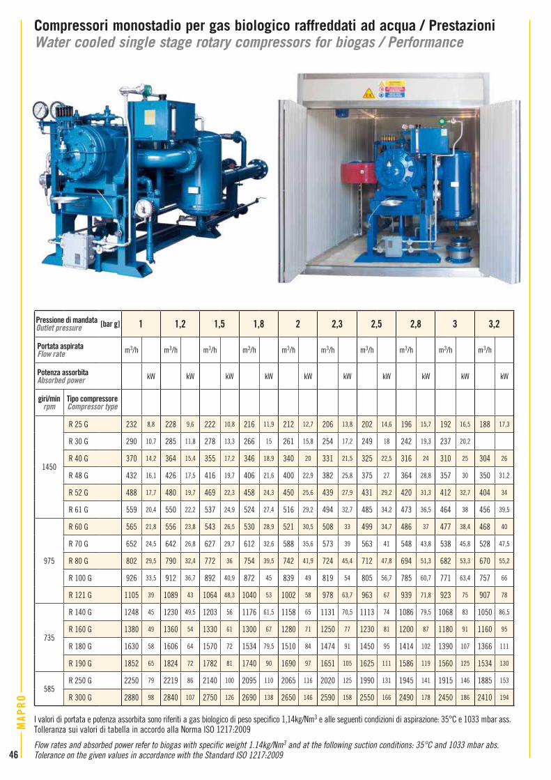
Compressori monostadio per gas biologico raffreddati ad acqua / PrestazioniWater cooled single stage rotary compressors for biogas / Performance
Pressione di mandataOutlet pressure [bar g] 1 1,2 1,5 1,8 2 2,3 2,5 2,8 3 3,2
Portata aspirataFlow rate m3/h m3/h m3/h m3/h m3/h m3/h m3/h m3/h m3/h m3/h
Potenza assorbitaAbsorbed power kW kW kW kW kW kW kW kW kW kW
giri/minrpm
Tipo compressore Compressor type
1450
R 25 G 232 8,8 228 9,6 222 10,8 216 11,9 212 12,7 206 13,8 202 14,6 196 15,7 192 16,5 188 17,3
R 30 G 290 10,7 285 11,8 278 13,3 266 15 261 15,8 254 17,2 249 18 242 19,3 237 20,2
R 40 G 370 14,2 364 15,4 355 17,2 346 18,9 340 20 331 21,5 325 22,5 316 24 310 25 304 26
R 48 G 432 16,1 426 17,5 416 19,7 406 21,6 400 22,9 382 25,8 375 27 364 28,8 357 30 350 31,2
R 52 G 488 17,7 480 19,7 469 22,3 458 24,3 450 25,6 439 27,9 431 29,2 420 31,3 412 32,7 404 34
R 61 G 559 20,4 550 22,2 537 24,9 524 27,4 516 29,2 494 32,7 485 34,2 473 36,5 464 38 456 39,5
975
R 60 G 565 21,8 556 23,8 543 26,5 530 28,9 521 30,5 508 33 499 34,7 486 37 477 38,4 468 40
R 70 G 652 24,5 642 26,8 627 29,7 612 32,6 588 35,6 573 39 563 41 548 43,8 538 45,8 528 47,5
R 80 G 802 29,5 790 32,4 772 36 754 39,5 742 41,9 724 45,4 712 47,8 694 51,3 682 53,3 670 55,2
R 100 G 926 33,5 912 36,7 892 40,9 872 45 839 49 819 54 805 56,7 785 60,7 771 63,4 757 66
R 121 G 1105 39 1089 43 1064 48,3 1040 53 1002 58 978 63,7 963 67 939 71,8 923 75 907 78
735
R 140 G 1248 45 1230 49,5 1203 56 1176 61,5 1158 65 1131 70,5 1113 74 1086 79,5 1068 83 1050 86,5
R 160 G 1380 49 1360 54 1330 61 1300 67 1280 71 1250 77 1230 81 1200 87 1180 91 1160 95
R 180 G 1630 58 1606 64 1570 72 1534 79,5 1510 84 1474 91 1450 95 1414 102 1390 107 1366 111
R 190 G 1852 65 1824 72 1782 81 1740 90 1690 97 1651 105 1625 111 1586 119 1560 125 1534 130
585R 250 G 2250 79 2219 86 2140 100 2095 110 2065 116 2020 125 1990 131 1945 141 1915 146 1885 153
R 300 G 2880 98 2840 107 2750 126 2690 138 2650 146 2590 158 2550 166 2490 178 2450 186 2410 194
I valori di portata e potenza assorbita sono riferiti a gas biologico di peso specifico 1,14kg/Nm3 e alle seguenti condizioni di aspirazione: 35°C e 1033 mbar ass.Tolleranza sui valori di tabella in accordo alla Norma ISO 1217:2009
Flow rates and absorbed power refer to biogas with specific weight 1.14kg/Nm3 and at the following suction conditions: 35°C and 1033 mbar abs. Tolerance on the given values in accordance with the Standard ISO 1217:200946
MAP
RO

Compressori monostadio per gas biologico raffreddati ad acqua / DimensioniWater cooled single stage rotary compressors for biogas / Dimensions
Dimensioni [mm] - Dimensions [mm]
Tipo compressoreCompressor type A B C D E ØF G H I L M N O P Q
ASPIRAZIONEINLET
MANDATAOUTLET
PesoWeight
[kg]EN 1092-1 EN 1092-1
R 25 G 1000 1480 1380 10 95 16 885 505 800 1220 1080 760 680 1470 915PN16 DN65 PN16 DN50
570
R 30 G 1000 1480 1380 10 95 16 885 505 800 1220 1080 760 680 1470 915 570
R 40 G 1270 1680 1380 105 125 16 1000 550 980 1400 1260 800 720 1715 1065
PN16 DN80 PN16 DN65
820
R 48 G 1270 1680 1380 105 125 16 1000 550 980 1400 1260 800 720 1715 1065 860
R 52 G 1270 1680 1380 105 125 16 1000 550 980 1400 1260 800 720 1775 1065 900
R 61 G 1270 1680 1380 105 125 16 1000 550 980 1400 1260 800 720 1775 1065 930
R 60 G 1650 1890 1580 200 180 20 1050 730 1325 1600 1400 960 900 2015 1135
PN16 DN125
PN16 DN100
1500
R 70 G 1675 1890 1580 200 180 20 1050 730 1325 1600 1400 960 900 2015 1135 1530
R 80 G 1675 2210 1580 200 180 20 1295 730 1325 1850 1650 960 900 2365 1365 1830
R 100 G 1675 2220 1580 200 180 20 1295 730 1325 1850 1650 960 900 2370 1365PN16 DN125
1800
R 121 G 1675 2355 1580 200 180 20 1295 730 1325 1935 1735 960 900 2480 1445 1950
R 140 G 2045 2445 1580 185 435 20 1410 695 1455 2000 1800 1100 1040 2545 1360PN16 DN150 PN16 DN150
2250
R 160 G 2045 2445 1580 185 435 20 1410 695 1455 2000 1800 1100 1040 2620 1360 2600
R 180 G 2050 2515 1790 190 435 20 1480 830 1740 2200 2000 1100 1040 2620 1360PN16 DN200 PN16 DN200
3100
R 190 G 2050 2515 1790 190 435 20 1480 830 1740 2200 2000 1100 1040 2620 1360 3050
Il disegno d’ingombro riporta, a titolo indicativo, le dimensioni dei compressori nella tipica composizione di fornitura prevista allorchè il loro utilizzo è quello della miscelazione di fanghi in digestori anaerobici.I pesi, riportati anch’essi a titolo indicativo, si intendono per gruppi equipaggiati con il motore elettrico di potenza maggiore tra quelle previste per lo specifico tipo di compressore. I motori considerati sono del tipo antideflagrante, con modo di protezione “d”, marcatura specifica Ex II 2 G, marcatura complementare Ex-d IIB T3.La quota “P” fa anch’essa riferimento a compressori equipaggiati con motore elettrico della massima potenza prevista.La quota “P” può inoltre variare in funzione della marca del motore installato. Per le dimensioni dei compressori R 250 G ed R 300 G, dei compressori utilizzati per l’alimentazione a motori a gas e per gruppi package specifici, vi preghiamo di contattare il Servizio Vendite MAPRO®.
On the drawing below you can find, for informational purposes only, the dimensions of the typical compressors to be used for sludge mixing into anaerobic digesters.The weights, given as well for informational purposes only, refer to machines equipped with electric motor of highest power among those provided for the specific compressor. The electric motors considered are type of protection “d”, flameproof, with specific marking Ex II 2 G, additional marking Ex-d IIB T3.Also the dimension “P” is for compressors equipped with electric motor of the highest power. And the dimension “P” can be different depending on the motor brand.For the dimensions of the compressors R 250 G and R 300 G, of the compressors to be used for gas engines feeding and for the dimensions of any specific “Package”, please ask MAPRO® Sales Department.
By-pass di avviamento a vuoto (opzionale)By-pass for the unloaded starting (optional)
MAP
RO
47

COD. 0108 - GAS 10-18 IT-EN
Soffianti e aspiratori centrifughi multistadio per ariaMultistage centrifugal blowers and exhausters for air
Soffianti e aspiratori a lobi rotanti per ariaPositive displacement blowers and exhausters for air
Compressori rotativi a palette per ariaSliding vane rotary compressors for air
Ventilatori centrifughi per aria
Centrifugal fans for air
Pompe per vuoto rotative apalette a ricircolo d’olio e a secco
Rotary vane vacuum pumps,oil recirculating type and oil free
Altri prodotti MAPRO®
Questo catalogo ha unicamente scopo informativo. Prestazioni e caratteristiche dei prodotti non possono essere considerate vincolanti.Nella logica del miglioramento continuo il catalogo è soggetto a revisione. Per informazioni sulla versione in vigore, contattare il Servizio Vendite.
This catalogue is for informational purposes only. It should not be considered as a binding description of the products or their performance.In the logic of continuous improvement, the catalogue is subject to revision. Please contact our Sales Department for information on the version in force.
Unità produttiva “Vesuvio” “Vesuvio” factory
Unità produttiva “Fermi” “Fermi” factory Unità produttiva “Cinisello” “Cinisello” factory
MAPRO INTERNATIONAL SpAMacchine Pneumatiche RotativeVia Vesuvio, 220834 NOVA MILANESE (MB) - ItalyTel. +39 0362 366356Fax +39 0362 450342E-mail: [email protected] • www.maproint.com
®
Other MAPRO® products
Soffianti e aspiratori a canale laterale per aria
Side channel blowers and exhausters for air