Side-By-Side Refrigerator ARISTON MSZ 70 NF...
88
Merloni Elettrodomestici Instruction Manual Language Edition Page Side-By-Side Refrigerator – Ariston MSZ 70 NF EN 2004.11.11 1 - 88 I I n n s s t t r r u u c c t t i i o o n n M M a a n n u u a a l l S S i i d d e e - - B B y y - - S S i i d d e e R R e e f f r r i i g g e e r r a a t t o o r r A A R R I I S S T T O O N N M M S S Z Z 7 7 0 0 N N F F C C O O O O L L I I N N G G 2 2 0 0 0 0 4 4 Contents of the Manual: Note for the Technician This manual is a supporting document for technical personnel; it contains a description of the various product types, the general operating principle, and other useful information. Technical personnel should anyway consult the specific model on Service Net (www.servicenet.merloni.com) to gain access to data and updates of electrical diagrams, technical bulletins, and spare parts. All the parts included in this document are the property of Merloni Elettrodomestici S.p.A. All rights reserved. This document and the information it contains are supplied without liability for possible errors or omissions. No part of it can be reproduced, used or copied without written permission or without being authorised by the terms of a contract clause.
Transcript of Side-By-Side Refrigerator ARISTON MSZ 70 NF...
Merloni Elettrodomestici
Instruction Manual Language Edition Page Side-By-Side Refrigerator – Ariston MSZ 70 NF EN 2004.11.11 1 - 88
IInnssttrruuccttiioonn MMaannuuaall
SSiiddee--BByy--SSiiddee RReeffrriiggeerraattoorr AARRIISSTTOONN MMSSZZ 7700 NNFF CCOOOOLLIINNGG 22000044
Contents of the Manual: Note for the Technician This manual is a supporting document for technical personnel; it contains a description of the various product types, the general operating principle, and other useful information. Technical personnel should anyway consult the specific model on Service Net (www.servicenet.merloni.com) to gain access to data and updates of electrical diagrams, technical bulletins, and spare parts.
All the parts included in this document are the property of Merloni Elettrodomestici S.p.A. All rights reserved. This document and the information it contains are supplied without liability for possible errors or omissions. No part of it can be reproduced, used or copied without written permission or without being authorised by the terms of a contract clause.
Merloni Elettrodomestici
Instruction Manual Language Edition Page Side-By-Side Refrigerator – Ariston MSZ 70 NF EN 2004.11.11 2 - 88
CCOONNTTEENNTTSS
1. Product Type......................................................................................................................4 1.1. KEY........................................................................................................................................................... 4 1.2. Photo: MSZ 701 NF HB (T) ...................................................................................................................... 4 1.3. Product Specifications .............................................................................................................................. 5
1.3.1. Dimensions: MSZ 70 NF HB (T)........................................................................................................ 5 1.3.2. Dimensions: MSZ 70 NF (T).............................................................................................................. 6 1.3.3. Key to Components ........................................................................................................................... 7 1.3.4. Product Energy Label ........................................................................................................................ 8
1.4. Operating Principle ................................................................................................................................... 9 1.4.1. Chilled Air Circulation ...................................................................................................................... 10 1.4.2. Refrigerant and Chilled Air Circulation Circuit ................................................................................. 11 1.4.3. Refrigerant circuit flow diagram....................................................................................................... 12 1.4.4. Technical Specifications .................................................................................................................. 12
1.5. Programs and Functions......................................................................................................................... 13 1.5.1. Display / Control Panel .................................................................................................................... 13 1.5.2. Freezer Temperature Control (FC).................................................................................................. 15 1.5.3. Super Freeze................................................................................................................................... 16 1.5.4. Refrigerator Temperature Control (RC)........................................................................................... 16 1.5.5. Control of Normal / Load / Fan modes ............................................................................................ 18 1.5.6. Defrost Cycle ................................................................................................................................... 22 1.5.7. Defrost Mode ................................................................................................................................... 24 1.5.8. Presentation of Errors on Display.................................................................................................... 25 1.5.9. Forced Defrost................................................................................................................................. 28 1.5.10. Initial defrosting ............................................................................................................................... 28 1.5.11. Audible Signal Or Alarm .................................................................................................................. 28 1.5.12. Post Delivery Explanations.............................................................................................................. 29 1.5.13. Compressor Restart Safety Device ................................................................................................. 29 1.5.14. Back Up Function ............................................................................................................................ 29 1.5.15. Electrical Components Start Delay.................................................................................................. 30 1.5.16. Home Bar Heating Element (Cooling Centre) ................................................................................. 30 1.5.17. Interior Lights Control ...................................................................................................................... 31 1.5.18. Demonstration Function .................................................................................................................. 31 1.5.19. Adjustment of Fridge Probe Off Set-Point ....................................................................................... 32 1.5.20. Functions Summary......................................................................................................................... 33 1.5.21. Automatic Ice Maker........................................................................................................................ 34 1.5.22. Dispenser Control Function ............................................................................................................. 38
1.6. Components............................................................................................................................................ 40 1.6.1. Condenser Fan Solenoid Valve Disassembly ................................................................................. 48 1.6.2. Removal of Main PCB ..................................................................................................................... 49 1.6.3. Removing the Dispenser Surround ................................................................................................. 49 1.6.4. Removing the Display PCB ............................................................................................................. 50 1.6.5. Removing the Dispenser Microswitch ............................................................................................. 51 1.6.6. Removing the Ice Flap Cover .......................................................................................................... 52 1.6.7. Removing the Door Handle ............................................................................................................. 53 1.6.8. Removing Freezer Cavity Internal Components ............................................................................. 53 1.6.9. Freezer Probe Removal .................................................................................................................. 56 1.6.10. Removing the Evaporator Coil ........................................................................................................ 56 1.6.11. Removing Fridge Cavity Internal Components................................................................................ 57 1.6.12. Removing the fridge cavity lamps cover.......................................................................................... 57 1.6.13. Removing the Fridge Cavity Probe ................................................................................................. 57 1.6.14. Removing the Water Container ....................................................................................................... 58 1.6.15. Removing the Fridge/Freezer Door Seals....................................................................................... 58 1.6.16. Removing the Home Bar Seals ....................................................................................................... 58
2. Wiring Diagrams ..............................................................................................................59
Merloni Elettrodomestici
Instruction Manual Language Edition Page Side-By-Side Refrigerator – Ariston MSZ 70 NF EN 2004.11.11 3 - 88
2.1. Power Supply.......................................................................................................................................... 59 2.1.1. Functions of Each Probe ................................................................................................................. 60 2.1.2. Relay Functions............................................................................................................................... 61 2.1.3. Wiring............................................................................................................................................... 63 2.1.4. Fan Operation.................................................................................................................................. 64 2.1.5. Main Power PCB Circuit Diagram ................................................................................................... 65 2.1.6. Front Commands PCB Circuit Diagram .......................................................................................... 66 2.1.7. Ice Dispenser Description: Cubes and Crushed Ice ....................................................................... 67 2.1.8. Description of Water Filling and Distribution ................................................................................... 68
3. Assistance........................................................................................................................69 3.1. Safety and Precautions........................................................................................................................... 69 3.2. Disassembly............................................................................................................................................ 69
3.2.1. Removing the ice maker water filler pipe ........................................................................................ 70 3.2.2. From inside the freezer:................................................................................................................... 70 3.2.3. Removing / refitting the water tank.................................................................................................. 70 3.2.4. Removing and Refitting the Ice Crusher (Inside the ice container)................................................. 71 3.2.5. Removing / Refitting the Ice Maker ................................................................................................. 71 3.2.6. Ice maker – Connections................................................................................................................. 72 3.2.7. Ice tray rotation mechanism ............................................................................................................ 72 3.2.8. Removing and Refitting the Ice Crusher Solenoid and Motor ......................................................... 73 3.2.9. Ice dispenser solenoid and flap....................................................................................................... 73 3.2.10. Water / Ice dispenser switch............................................................................................................ 74 3.2.11. Removing the Doors........................................................................................................................ 74
4. Exploded Views of Product: MSZ701NFHB (34037)........................................................75 4.1. Exploded view 1: Side-by-Side ............................................................................................................... 75 4.2. Exploded view 2: Compressor Compartment ......................................................................................... 76 4.3. Exploded View 3: Fridge Accessories .................................................................................................... 77 4.4. Exploded View 4: Freezer Accessories .................................................................................................. 78 4.5. Exploded View 5: Freezer Door.............................................................................................................. 79 4.6. Exploded View 6: Fridge Door ................................................................................................................ 80
5. Appendix..........................................................................................................................81 5.1.1. Removing the Freezer Door ............................................................................................................ 81 5.1.2. Removing the Fridge Door .............................................................................................................. 82 5.1.3. Refitting the freezer door ................................................................................................................. 83 5.1.4. Refitting fridge door ......................................................................................................................... 84 5.1.5. Glossary........................................................................................................................................... 85
Merloni Elettrodomestici
Instruction Manual Language Edition Page Side-By-Side Refrigerator – Ariston MSZ 70 NF EN 2004.11.11 4 - 88
11.. PPRROODDUUCCTT TTYYPPEE
11..11.. KKEEYY
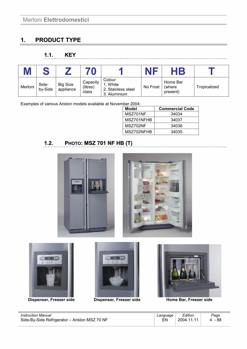
M S Z 70 1 NF HB T Merloni Side-
by-Side Big Size appliance
Capacity (litres) class
Colour 1. White 2. Stainless steel 3. Aluminium
No Frost Home Bar (where present)
Tropicalized
Examples of various Ariston models available at November 2004:
Model Commercial Code MSZ701NF 34034 MSZ701NFHB 34037 MSZ702NF 34036 MSZ702NFHB 34035
11..22.. PPHHOOTTOO:: MMSSZZ 770011 NNFF HHBB ((TT))
Dispenser, Freezer side Dispenser, Freezer side Home Bar, Freezer side
Merloni Elettrodomestici
Instruction Manual Language Edition Page Side-By-Side Refrigerator – Ariston MSZ 70 NF EN 2004.11.11 5 - 88
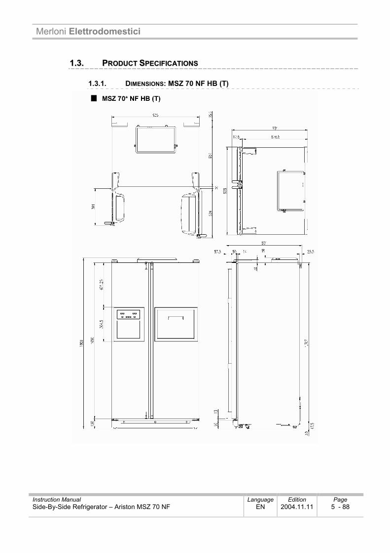
11..33.. PPRROODDUUCCTT SSPPEECCIIFFIICCAATTIIOONNSS
1.3.1. DIMENSIONS: MSZ 70 NF HB (T)
Merloni Elettrodomestici
Instruction Manual Language Edition Page Side-By-Side Refrigerator – Ariston MSZ 70 NF EN 2004.11.11 6 - 88
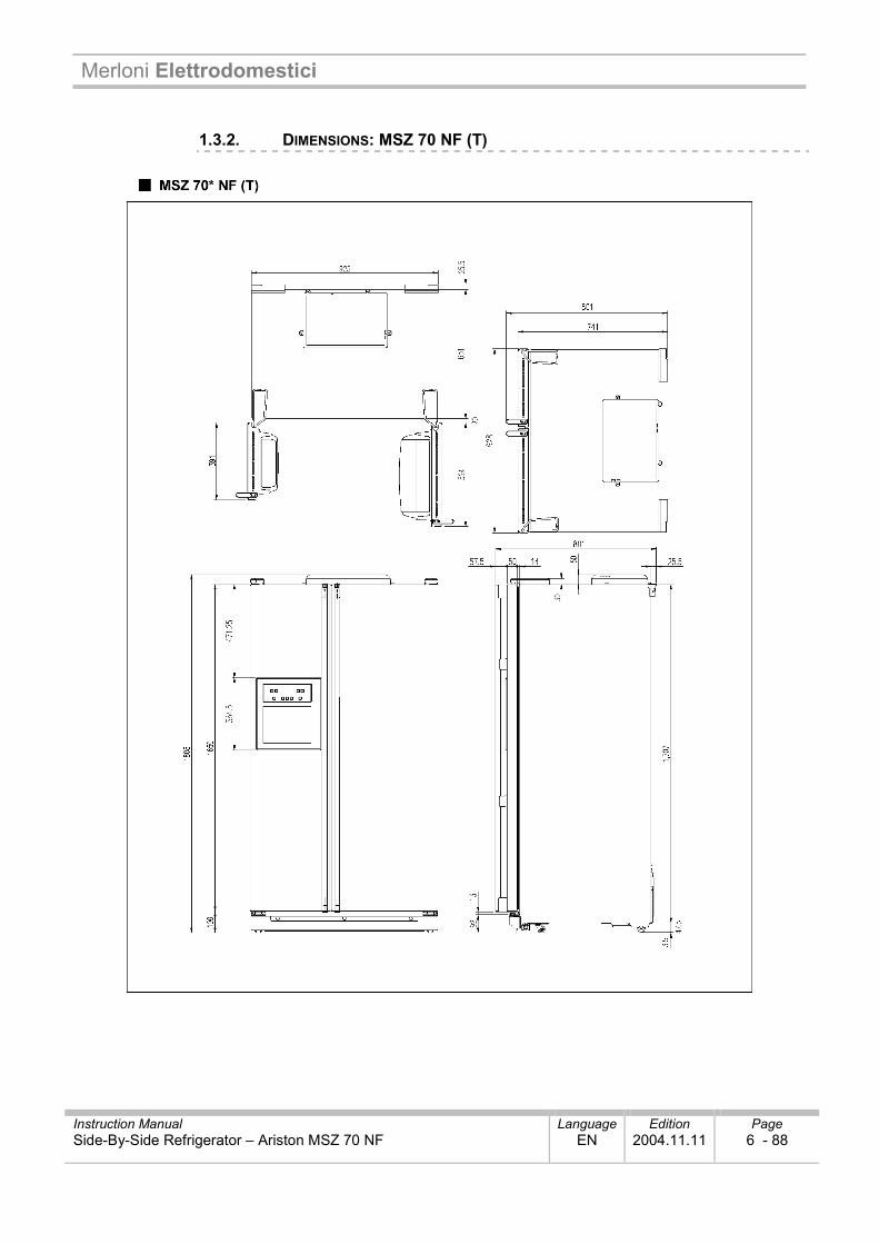
1.3.2. DIMENSIONS: MSZ 70 NF (T)
Merloni Elettrodomestici
Instruction Manual Language Edition Page Side-By-Side Refrigerator – Ariston MSZ 70 NF EN 2004.11.11 7 - 88
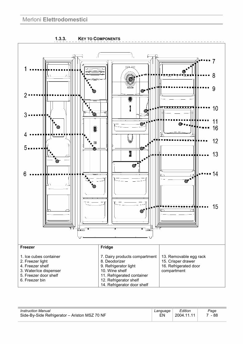
1.3.3. KEY TO COMPONENTS
Freezer 1. Ice cubes container 2. Freezer light 4. Freezer shelf 3. Water/ice dispenser 5. Freezer door shelf 6. Freezer bin
Fridge 7. Dairy products compartment 8. Deodorizer 9. Refrigerator light 10. Wine shelf 11. Refrigerated container 12. Refrigerator shelf 14. Refrigerator door shelf
13. Removable egg rack 15. Crisper drawer 16. Refrigerated door compartment

Merloni Elettrodomestici
Instruction Manual Language Edition Page Side-By-Side Refrigerator – Ariston MSZ 70 NF EN 2004.11.11 8 - 88
1.3.4. PRODUCT ENERGY LABEL
Diagram Photo
Merloni Elettrodomestici
Instruction Manual Language Edition Page Side-By-Side Refrigerator – Ariston MSZ 70 NF EN 2004.11.11 9 - 88
11..44.. OOPPEERRAATTIINNGG PPRRIINNCCIIPPLLEE
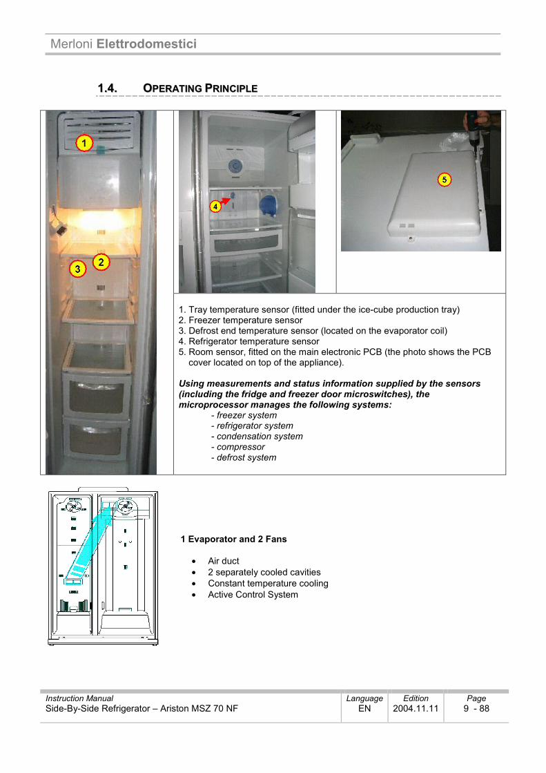
1. Tray temperature sensor (fitted under the ice-cube production tray) 2. Freezer temperature sensor 3. Defrost end temperature sensor (located on the evaporator coil) 4. Refrigerator temperature sensor 5. Room sensor, fitted on the main electronic PCB (the photo shows the PCB
cover located on top of the appliance). Using measurements and status information supplied by the sensors (including the fridge and freezer door microswitches), the microprocessor manages the following systems:
- freezer system - refrigerator system - condensation system - compressor - defrost system
1 Evaporator and 2 Fans
• Air duct • 2 separately cooled cavities • Constant temperature cooling • Active Control System
Merloni Elettrodomestici
Instruction Manual Language Edition Page Side-By-Side Refrigerator – Ariston MSZ 70 NF EN 2004.11.11 10 - 88
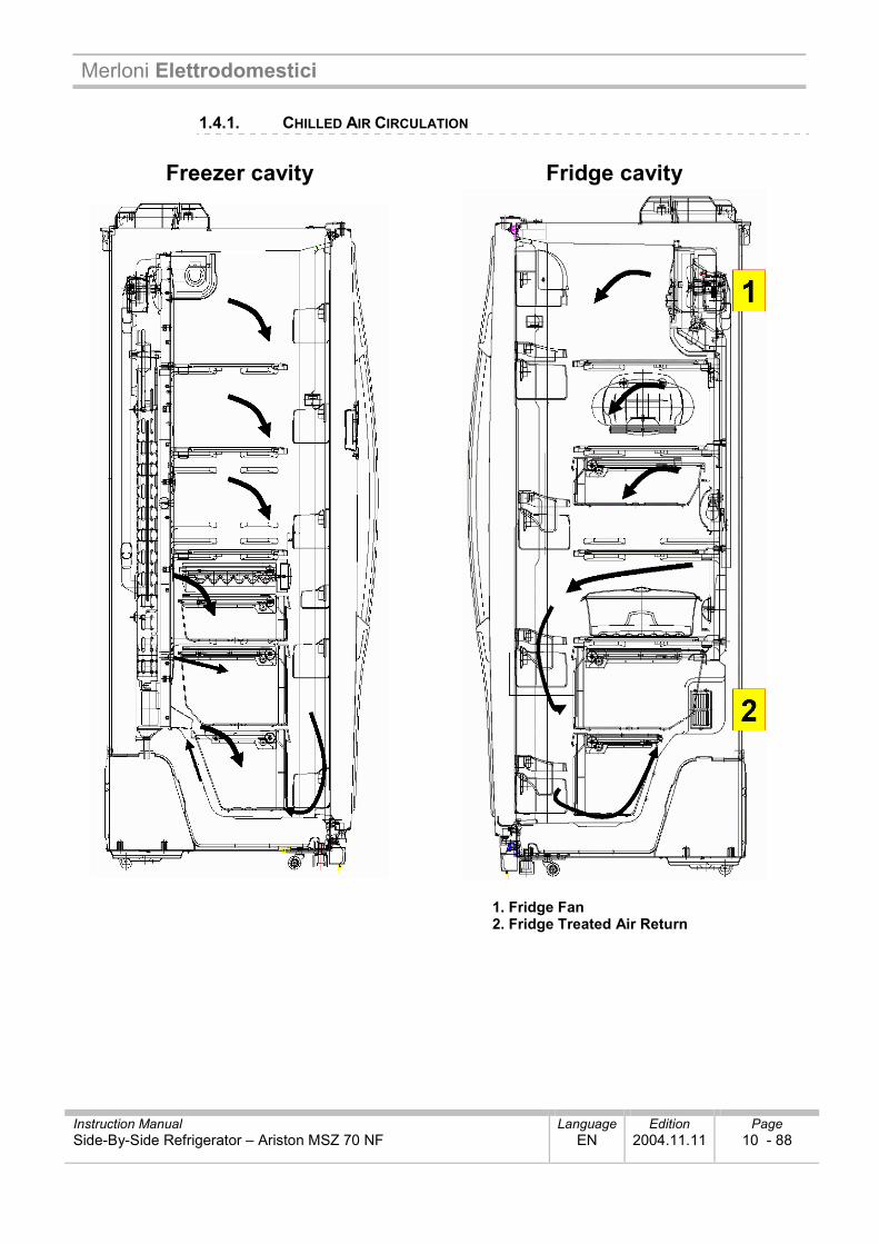
1.4.1. CHILLED AIR CIRCULATION
Freezer cavity Fridge cavity
1. Fridge Fan 2. Fridge Treated Air Return
Merloni Elettrodomestici
Instruction Manual Language Edition Page Side-By-Side Refrigerator – Ariston MSZ 70 NF EN 2004.11.11 11 - 88
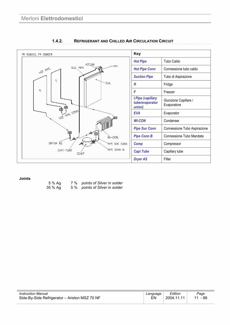
1.4.2. REFRIGERANT AND CHILLED AIR CIRCULATION CIRCUIT
Key
Hot Pipe Tubo Caldo
Hot Pipe Conn Connessione tubo caldo
Suction Pipe Tubo di Aspirazione
R Fridge
F Freezer I.Pipe (capillary tube/evaporator union)
Giunzione Capillare / Evaporatore
EVA Evaporator
WI-CON Condenser
Pipe Suc Conn Connessione Tubo Aspirazione
Pipe Conn B Connessione Tubo Mandata
Comp Compressor
Capi Tube Capillary tube
Dryer AS Filter Joints 5 % Ag 7 % points of Silver in solder 35 % Ag 5 % points of Silver in solder
Merloni Elettrodomestici
Instruction Manual Language Edition Page Side-By-Side Refrigerator – Ariston MSZ 70 NF EN 2004.11.11 12 - 88
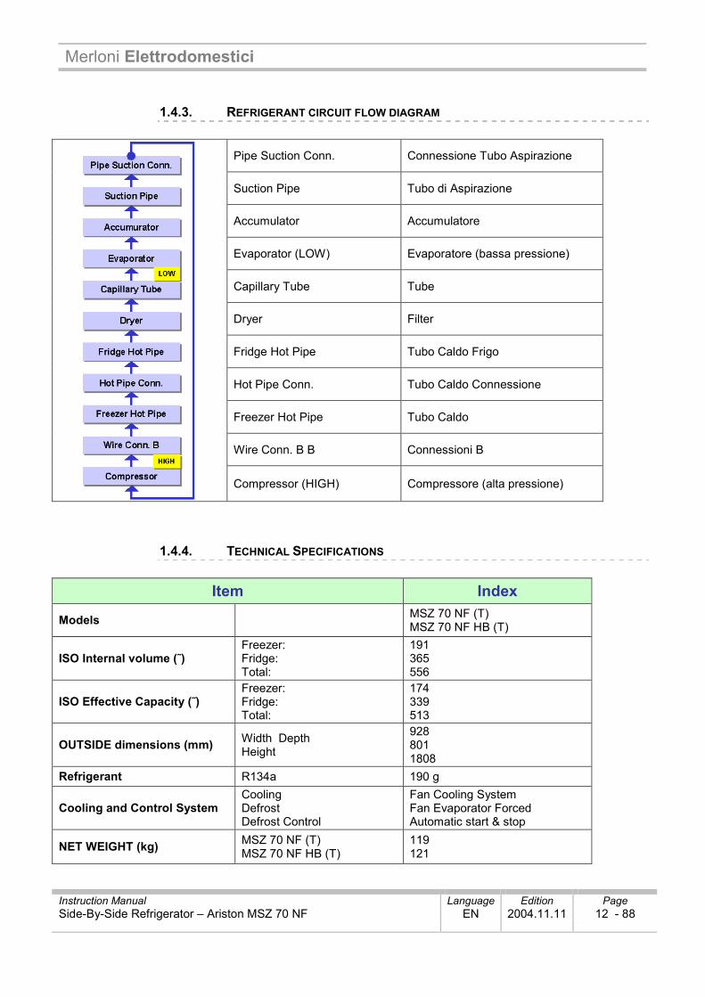
1.4.3. REFRIGERANT CIRCUIT FLOW DIAGRAM
Pipe Suction Conn. Connessione Tubo Aspirazione
Suction Pipe Tubo di Aspirazione
Accumulator Accumulatore
Evaporator (LOW) Evaporatore (bassa pressione)
Capillary Tube Tube
Dryer Filter
Fridge Hot Pipe Tubo Caldo Frigo
Hot Pipe Conn. Tubo Caldo Connessione
Freezer Hot Pipe Tubo Caldo
Wire Conn. B B Connessioni B
Compressor (HIGH) Compressore (alta pressione)
1.4.4. TECHNICAL SPECIFICATIONS
Item Index
Models MSZ 70 NF (T) MSZ 70 NF HB (T)
ISO Internal volume (˜) Freezer: Fridge: Total:
191 365 556
ISO Effective Capacity (˜) Freezer: Fridge: Total:
174 339 513
OUTSIDE dimensions (mm) Width Depth Height
928 801 1808
Refrigerant R134a 190 g
Cooling and Control System Cooling Defrost Defrost Control
Fan Cooling System Fan Evaporator Forced Automatic start & stop
NET WEIGHT (kg) MSZ 70 NF (T) MSZ 70 NF HB (T)
119 121
Merloni Elettrodomestici
Instruction Manual Language Edition Page Side-By-Side Refrigerator – Ariston MSZ 70 NF EN 2004.11.11 13 - 88
11..55.. PPRROOGGRRAAMMSS AANNDD FFUUNNCCTTIIOONNSS
1.5.1. DISPLAY / CONTROL PANEL
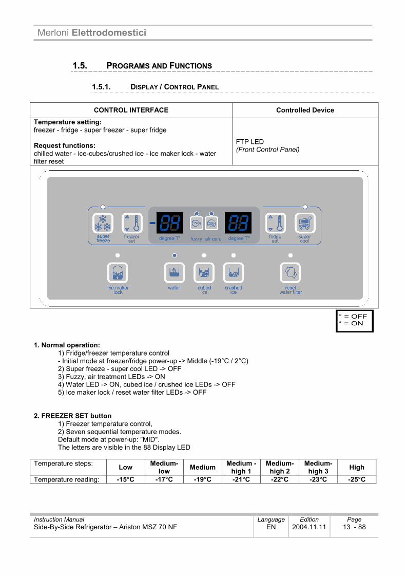
CONTROL INTERFACE Controlled Device
Temperature setting: freezer - fridge - super freezer - super fridge Request functions: chilled water - ice-cubes/crushed ice - ice maker lock - water filter reset
FTP LED (Front Control Panel)
1. Normal operation:
1) Fridge/freezer temperature control - Initial mode at freezer/fridge power-up -> Middle (-19°C / 2°C) 2) Super freeze - super cool LED -> OFF 3) Fuzzy, air treatment LEDs -> ON 4) Water LED -> ON, cubed ice / crushed ice LEDs -> OFF 5) Ice maker lock / reset water filter LEDs -> OFF
2. FREEZER SET button
1) Freezer temperature control, 2) Seven sequential temperature modes. Default mode at power-up: "MID". The letters are visible in the 88 Display LED
Temperature steps: Low Medium-
low Medium Medium -high 1
Medium-high 2
Medium-high 3 High
Temperature reading: -15°C -17°C -19°C -21°C -22°C -23°C -25°C
Merloni Elettrodomestici
Instruction Manual Language Edition Page Side-By-Side Refrigerator – Ariston MSZ 70 NF EN 2004.11.11 14 - 88
3. SUPER FREEZE button LED illuminates with mode selected. 4. FRIDGE SET button
1) Refrigerator temperature control 2) Five sequential temperature modes Default mode at power-up: "MID". The letters are visible in the 88 Display LED.
Temperature steps: Low Medium-
low Medium Medium-high High
Temperature reading: 4°C 3°C 2°C 1°C 0°C 5. Super Cool button LED illuminates with mode selected. 6. Water / Cubed Ice / Crushed Ice button
1) Select water / Cubed ice / Crushed ice 2) LED illuminates to show active selection Default mode at power-up: WATER 3) CUBED ICE or CRUSHED ICE function continues for 1 hour and then switches to WATER (WATER LED illuminates)
7. Ice Maker Lock button
Start with ICE MAKER LOCK button ICE MAKER LOCK button is active (ON), WATER icon is always active (ON)
Stop by pressing ICE MAKER LOCK button again ICE MAKER LOCK LED is extinguished (OFF), WATER icon is active (ON).
8. Filter information
Normal filter conditions (LED OFF) proceed for six months from the first power-up The LED illuminates after 6 months. How to reset filter information
Change the filter and then press the RESET WATER FILTER button and hold it down for 5 seconds
Merloni Elettrodomestici
Instruction Manual Language Edition Page Side-By-Side Refrigerator – Ariston MSZ 70 NF EN 2004.11.11 15 - 88
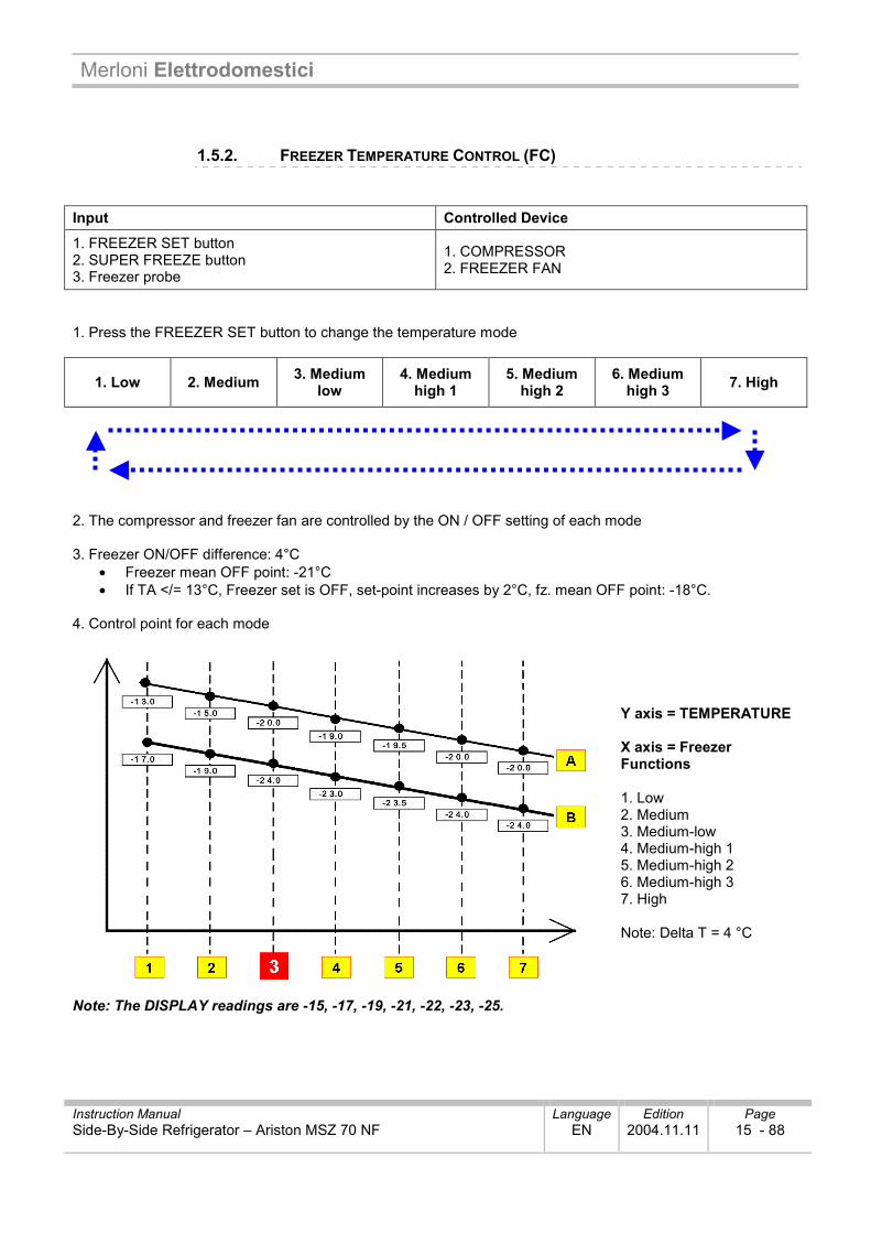
1.5.2. FREEZER TEMPERATURE CONTROL (FC) Input Controlled Device
1. FREEZER SET button 2. SUPER FREEZE button 3. Freezer probe
1. COMPRESSOR 2. FREEZER FAN
1. Press the FREEZER SET button to change the temperature mode
1. Low 2. Medium 3. Medium low
4. Medium high 1
5. Medium high 2
6. Medium high 3 7. High
2. The compressor and freezer fan are controlled by the ON / OFF setting of each mode 3. Freezer ON/OFF difference: 4°C
• Freezer mean OFF point: -21°C • If TA </= 13°C, Freezer set is OFF, set-point increases by 2°C, fz. mean OFF point: -18°C.
4. Control point for each mode
Y axis = TEMPERATURE X axis = Freezer Functions 1. Low 2. Medium 3. Medium-low 4. Medium-high 1 5. Medium-high 2 6. Medium-high 3 7. High Note: Delta T = 4 °C
Note: The DISPLAY readings are -15, -17, -19, -21, -22, -23, -25.
Merloni Elettrodomestici
Instruction Manual Language Edition Page Side-By-Side Refrigerator – Ariston MSZ 70 NF EN 2004.11.11 16 - 88
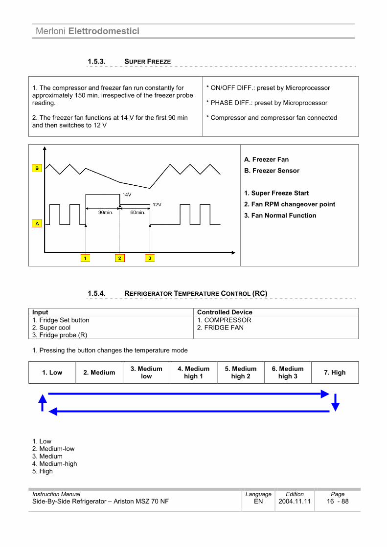
1.5.3. SUPER FREEZE 1. The compressor and freezer fan run constantly for approximately 150 min. irrespective of the freezer probe reading. 2. The freezer fan functions at 14 V for the first 90 min and then switches to 12 V
* ON/OFF DIFF.: preset by Microprocessor * PHASE DIFF.: preset by Microprocessor * Compressor and compressor fan connected
A. Freezer Fan B. Freezer Sensor
1. Super Freeze Start 2. Fan RPM changeover point
3. Fan Normal Function
1.5.4. REFRIGERATOR TEMPERATURE CONTROL (RC) Input Controlled Device 1. Fridge Set button 2. Super cool 3. Fridge probe (R)
1. COMPRESSOR 2. FRIDGE FAN
1. Pressing the button changes the temperature mode
1. Low 2. Medium 3. Medium low
4. Medium high 1
5. Medium high 2
6. Medium high 3 7. High
1. Low 2. Medium-low 3. Medium 4. Medium-high 5. High
Merloni Elettrodomestici
Instruction Manual Language Edition Page Side-By-Side Refrigerator – Ariston MSZ 70 NF EN 2004.11.11 17 - 88
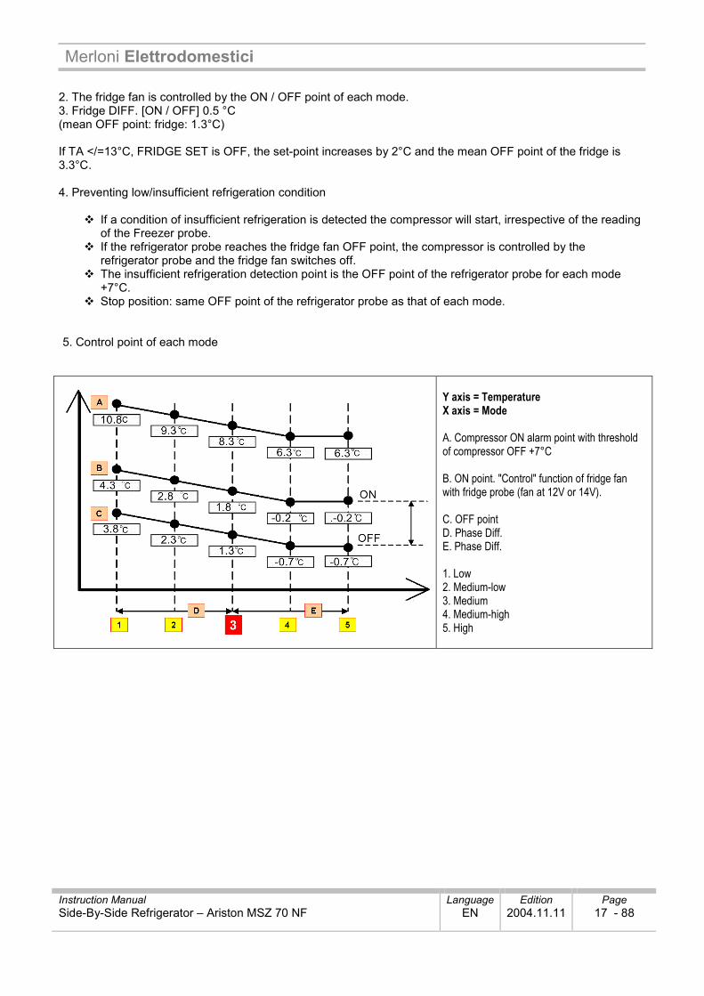
2. The fridge fan is controlled by the ON / OFF point of each mode. 3. Fridge DIFF. [ON / OFF] 0.5 °C (mean OFF point: fridge: 1.3°C) If TA </=13°C, FRIDGE SET is OFF, the set-point increases by 2°C and the mean OFF point of the fridge is 3.3°C. 4. Preventing low/insufficient refrigeration condition
If a condition of insufficient refrigeration is detected the compressor will start, irrespective of the reading of the Freezer probe. If the refrigerator probe reaches the fridge fan OFF point, the compressor is controlled by the refrigerator probe and the fridge fan switches off. The insufficient refrigeration detection point is the OFF point of the refrigerator probe for each mode +7°C. Stop position: same OFF point of the refrigerator probe as that of each mode.
5. Control point of each mode
Y axis = Temperature X axis = Mode A. Compressor ON alarm point with threshold of compressor OFF +7°C B. ON point. "Control" function of fridge fan with fridge probe (fan at 12V or 14V). C. OFF point D. Phase Diff. E. Phase Diff. 1. Low 2. Medium-low 3. Medium 4. Medium-high 5. High
Merloni Elettrodomestici
Instruction Manual Language Edition Page Side-By-Side Refrigerator – Ariston MSZ 70 NF EN 2004.11.11 18 - 88
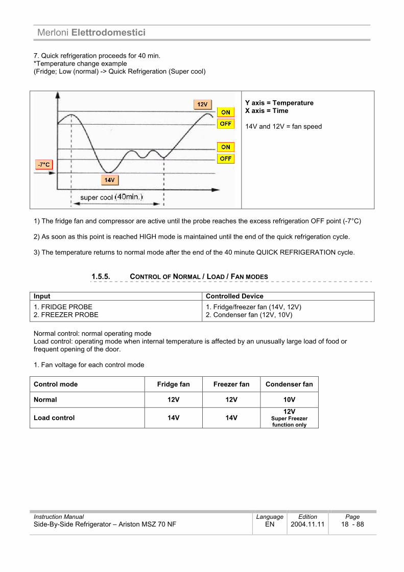
7. Quick refrigeration proceeds for 40 min. *Temperature change example (Fridge; Low (normal) -> Quick Refrigeration (Super cool)
Y axis = Temperature X axis = Time 14V and 12V = fan speed
1) The fridge fan and compressor are active until the probe reaches the excess refrigeration OFF point (-7°C) 2) As soon as this point is reached HIGH mode is maintained until the end of the quick refrigeration cycle. 3) The temperature returns to normal mode after the end of the 40 minute QUICK REFRIGERATION cycle.
1.5.5. CONTROL OF NORMAL / LOAD / FAN MODES Input Controlled Device 1. FRIDGE PROBE 2. FREEZER PROBE
1. Fridge/freezer fan (14V, 12V) 2. Condenser fan (12V, 10V)
Normal control: normal operating mode Load control: operating mode when internal temperature is affected by an unusually large load of food or frequent opening of the door. 1. Fan voltage for each control mode
Control mode Fridge fan Freezer fan Condenser fan
Normal 12V 12V 10V
Load control 14V 14V 12V
Super Freezer function only
Merloni Elettrodomestici
Instruction Manual Language Edition Page Side-By-Side Refrigerator – Ariston MSZ 70 NF EN 2004.11.11 19 - 88
2. Load control
1) Aim: Immediate restoral of set freezer/fridge temperature due to temperature rise caused by load (excessive food quantity) and frequent door opening
2) Start conditions Fridge/freezer door opening time is more than 30 seconds each time. The fridge or freezer load control starts (depending on the case in question). Higher than [Fridge probe ON point +5°C --> Fridge load control Higher than [Freezer probe ON point +5°C --> Freezer load control
3) Conditions to avoid load control Initial starting (at power-up) - Initial starting (at power-up) Immediately after the pre-cooling, evaporator defrost, defrost pause cycles. After door opening load control starts checking for required conditions. 4) Control method
4-1) On the basis of the fridge / freezer door opening time (more than 30 seconds) the fridge / freezer fan operates at 14 V 4-2) Freezer probe ON point + 5°C: freezer fan operates at 14 V 4-3) Control on basis of fridge probe ON point + 5°C. Fridge fan operates at 14V. 4-4) Condenser fan normally operates at 10V.
5) Stop conditions - The mode proceeds for 20 min. If, at the end of the mode, another condition that requires it should occur, the mode will restart automatically. - When the position is reached (Freezer probe OFF point), freezer fan load control mode is suspended. - When the position is reached (Fridge probe OFF point), fridge fan load control mode is suspended.
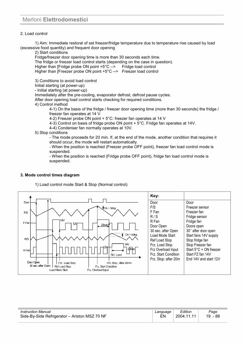
3. Mode control times diagram
1) Load control mode Start & Stop (Normal control)
Key: Door F/S F Fan R / S R Fan Door Open 30 sec. after Open Load Mode Start Ref Load Stop Frz. Load Stop Frz Overload Input Frz. Start Condition Frz. Stop: after 20m
Door Freezer sensor Freezer fan Fridge sensor Fridge fan Doors open 30’’ after door open Start fans 14V supply Stop fridge fan Stop Freezer fan Start 5°C + ON freezer Start FZ fan 14V End 14V and start 12V
Merloni Elettrodomestici
Instruction Manual Language Edition Page Side-By-Side Refrigerator – Ariston MSZ 70 NF EN 2004.11.11 20 - 88
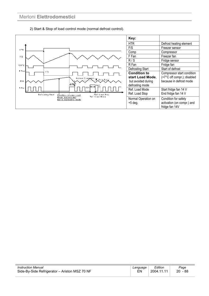
2) Start & Stop of load control mode (normal defrost control).
Key: HTR Defrost heating element F/S Freezer sensor Comp Compressor F Fan Freezer fan R / S Fridge sensor R Fan Fridge fan Defrosting Start Start of defrost Condition to start Load Mode, but avoided during defrosting mode
Compressor start condition (+7°C off compr.); disabled because in defrost mode
Ref. Load Mode Ref. Load Stop
Start fridge fan 14 V End fridge fan 14 V
Normal Operation on +5 deg.
Condition for safety activation (on compr.) and fridge fan 14V
Merloni Elettrodomestici
Instruction Manual Language Edition Page Side-By-Side Refrigerator – Ariston MSZ 70 NF EN 2004.11.11 21 - 88
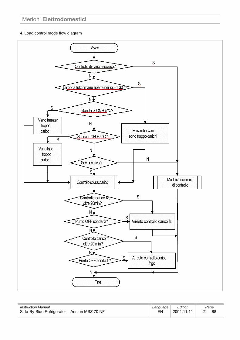
4. Load control mode flow diagram
Merloni Elettrodomestici
Instruction Manual Language Edition Page Side-By-Side Refrigerator – Ariston MSZ 70 NF EN 2004.11.11 22 - 88
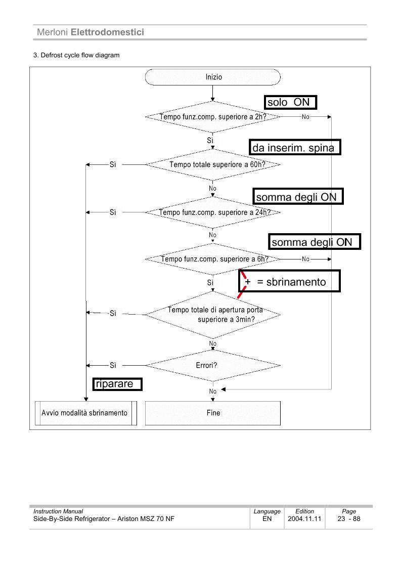
1.5.6. DEFROST CYCLE Input Controlled Device 1. Compressor total running time 2. Compressor operating rate 3. Total door opening time
1. Defrost mode
1. Condition for defrost cycle start
1) Total compressor operating time: 6, 8, ...24 hours (sum of ON times, can be 24, ....6 hours) 2) Total door open time: 3 min (Open time of each door - fr or fz - exceeds 3 min.) 3) Total time [comp. ON + comp. OFF]: 60 hours (from time appliance is plugged in) 4) Error mode: R1, F1, D1, F3, RT/S, door switch
2. Defrost mode start conditions
1) Defrost mode starts in the following conditions: - Occurrance of an error if total compressor operating time is 6.8.. 24h. - Total door open time more than 3 min. (Open time of each door - fr or fz - exceeds 3 min.)
2) Defrost mode starts automatically if total compressor operating time is 24 h, even if conditions 1) and 2) above are not present. 3) Defrost mode starts automatically as soon as total [comp. ON + comp. OFF] time exceeds 60h with appliance plugged in, even if conditions 1) and 2) above are not present
Merloni Elettrodomestici
Instruction Manual Language Edition Page Side-By-Side Refrigerator – Ariston MSZ 70 NF EN 2004.11.11 23 - 88
3. Defrost cycle flow diagram
Merloni Elettrodomestici
Instruction Manual Language Edition Page Side-By-Side Refrigerator – Ariston MSZ 70 NF EN 2004.11.11 24 - 88
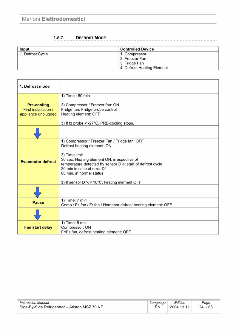
1.5.7. DEFROST MODE Input Controlled Device 1. Defrost Cycle 1. Compressor
2. Freezer Fan 3. Fridge Fan 4. Defrost Heating Element
1. Defrost mode
Pre-cooling First installation /
appliance unplugged
1) Time ; 50 min 2) Compressor / Freezer fan: ON Fridge fan: Fridge probe control Heating element: OFF 3) If fz probe < -27°C, PRE-cooling stops.
Evaporator defrost
1) Compressor / Freezer Fan / Fridge fan: OFF Defrost heating element: ON 2) Time limit 30 sec. Heating element ON, irrespective of temperature detected by sensor D at start of defrost cycle 30 min in case of error D1 80 min. in normal status 3) If sensor D >/= 10°C, heating element OFF
Pause 1) Time: 7 min Comp./ Fz fan / Fr fan / Homebar defrost heating element: OFF
Fan start delay 1) Time: 5 min Compressor: ON Fr/Fz fan, defrost heating element: OFF
Merloni Elettrodomestici
Instruction Manual Language Edition Page Side-By-Side Refrigerator – Ariston MSZ 70 NF EN 2004.11.11 25 - 88
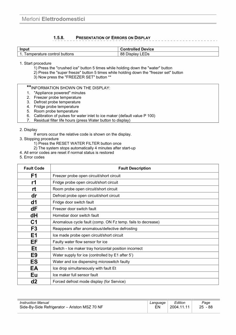
1.5.8. PRESENTATION OF ERRORS ON DISPLAY Input Controlled Device 1. Temperature control buttons 88 Display LEDs 1. Start procedure
1) Press the "crushed ice" button 5 times while holding down the "water" button 2) Press the "super freeze" button 5 times while holding down the "freezer set" button 3) Now press the "FREEZER SET" button **
**INFORMATION SHOWN ON THE DISPLAY: 1. "Appliance powered" minutes 2. Freezer probe temperature 3. Defrost probe temperature 4. Fridge probe temperature 5. Room probe temperature 6. Calibration of pulses for water inlet to ice maker (default value P 100) 7. Residual filter life hours (press Water button to display)
2. Display
If errors occur the relative code is shown on the display. 3. Stopping procedure
1) Press the RESET WATER FILTER button once 2) The system stops automatically 4 minutes after start-up
4. All error codes are reset if normal status is restored 5. Error codes
Fault Code Fault Description
F1 Freezer probe open circuit/short circuit
r1 Fridge probe open circuit/short circuit
rt Room probe open circuit/short circuit
dr Defrost probe open circuit/short circuit
d1 Fridge door switch fault
dF Freezer door switch fault
dH Homebar door switch fault
C1 Anomalous cycle fault (comp. ON Fz temp. fails to decrease)
F3 Reappears after anomalous/defective defrosting
E1 Ice made probe open circuit/short circuit
EF Faulty water flow sensor for ice
Et Switch - Ice maker tray horizontal position incorrect
E9 Water supply for ice (controlled by E1 after 5’)
ES Water and ice dispensing microswitch faulty
EA Ice drop simultaneously with fault Et
Eu Ice maker full sensor fault
d2 Forced defrost mode display (for Service)
Merloni Elettrodomestici
Instruction Manual Language Edition Page Side-By-Side Refrigerator – Ariston MSZ 70 NF EN 2004.11.11 26 - 88
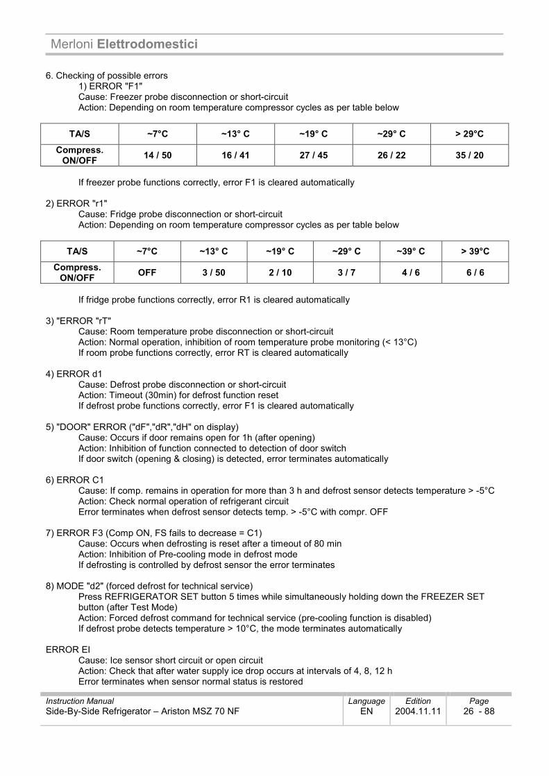
6. Checking of possible errors
1) ERROR "F1" Cause: Freezer probe disconnection or short-circuit Action: Depending on room temperature compressor cycles as per table below
TA/S ~7°C ~13° C ~19° C ~29° C > 29°C
Compress. ON/OFF 14 / 50 16 / 41 27 / 45 26 / 22 35 / 20
If freezer probe functions correctly, error F1 is cleared automatically
2) ERROR "r1"
Cause: Fridge probe disconnection or short-circuit Action: Depending on room temperature compressor cycles as per table below
TA/S ~7°C ~13° C ~19° C ~29° C ~39° C > 39°C
Compress. ON/OFF OFF 3 / 50 2 / 10 3 / 7 4 / 6 6 / 6
If fridge probe functions correctly, error R1 is cleared automatically
3) "ERROR "rT"
Cause: Room temperature probe disconnection or short-circuit Action: Normal operation, inhibition of room temperature probe monitoring (< 13°C) If room probe functions correctly, error RT is cleared automatically
4) ERROR d1
Cause: Defrost probe disconnection or short-circuit Action: Timeout (30min) for defrost function reset If defrost probe functions correctly, error F1 is cleared automatically
5) "DOOR" ERROR ("dF","dR","dH" on display)
Cause: Occurs if door remains open for 1h (after opening) Action: Inhibition of function connected to detection of door switch If door switch (opening & closing) is detected, error terminates automatically
6) ERROR C1
Cause: If comp. remains in operation for more than 3 h and defrost sensor detects temperature > -5°C Action: Check normal operation of refrigerant circuit Error terminates when defrost sensor detects temp. > -5°C with compr. OFF
7) ERROR F3 (Comp ON, FS fails to decrease = C1)
Cause: Occurs when defrosting is reset after a timeout of 80 min Action: Inhibition of Pre-cooling mode in defrost mode If defrosting is controlled by defrost sensor the error terminates
8) MODE "d2" (forced defrost for technical service)
Press REFRIGERATOR SET button 5 times while simultaneously holding down the FREEZER SET button (after Test Mode) Action: Forced defrost command for technical service (pre-cooling function is disabled) If defrost probe detects temperature > 10°C, the mode terminates automatically
ERROR EI
Cause: Ice sensor short circuit or open circuit Action: Check that after water supply ice drop occurs at intervals of 4, 8, 12 h Error terminates when sensor normal status is restored
Merloni Elettrodomestici
Instruction Manual Language Edition Page Side-By-Side Refrigerator – Ariston MSZ 70 NF EN 2004.11.11 27 - 88
10) ERROR EF
Cause: Occurs when flow sensor stops sending pulses for a certain period of time Number of pulses is less than 10/sec with water inlet solenoid valve powered Action: Check solenoid valve powered time (5.5 sec with EEPROM.) Error terminates when flow sensor is replaced.
11) ERROR E9
Cause: Temperature detected by ice sensor increases 5 m after water inlet Action: Normal procedure Error terminates when sensor detects correct temperature (IS detects insufficient water in ICE tray)
12) ERROR ES (DISPENSER MICROSWITCH)
Cause: When microswitch is active for more than 1 minute Action: Stops ice distribution and crushing function. Display: Ice dispensing LED extinguished. Error terminates when switch returns to normal status
13) Ice drop motor operation fault
Cause: Motor malfunction Action: Press TEST SWITCH button Renew motor
14) ERROR Eu
Cause: Switch responsible for detecting ice tray full condition generates error Action: When ice is dropped microswitch fails to return to ON position Error terminates when switch returns to normal status
15) ERROR EA (tray rotation motor error)
Cause: Ice drop is detected 3 times by the sensor with the level sensor switch signalling an error condition Action: Stop operation of ice maker Error terminates when level sensor switch returns to normal status * Switch off power supply and then switch on again or press test switch
16) ERROR Et
Cause: Occurs when level sensor signals an error (no pulses detected for a certain period of time) Action: By time (supply mode no longer valid) (tray horizontal position) Error terminates when sensor normal status is restored * When all ERROR CODES are normal, fridge settings are all reset.
Merloni Elettrodomestici
Instruction Manual Language Edition Page Side-By-Side Refrigerator – Ariston MSZ 70 NF EN 2004.11.11 28 - 88
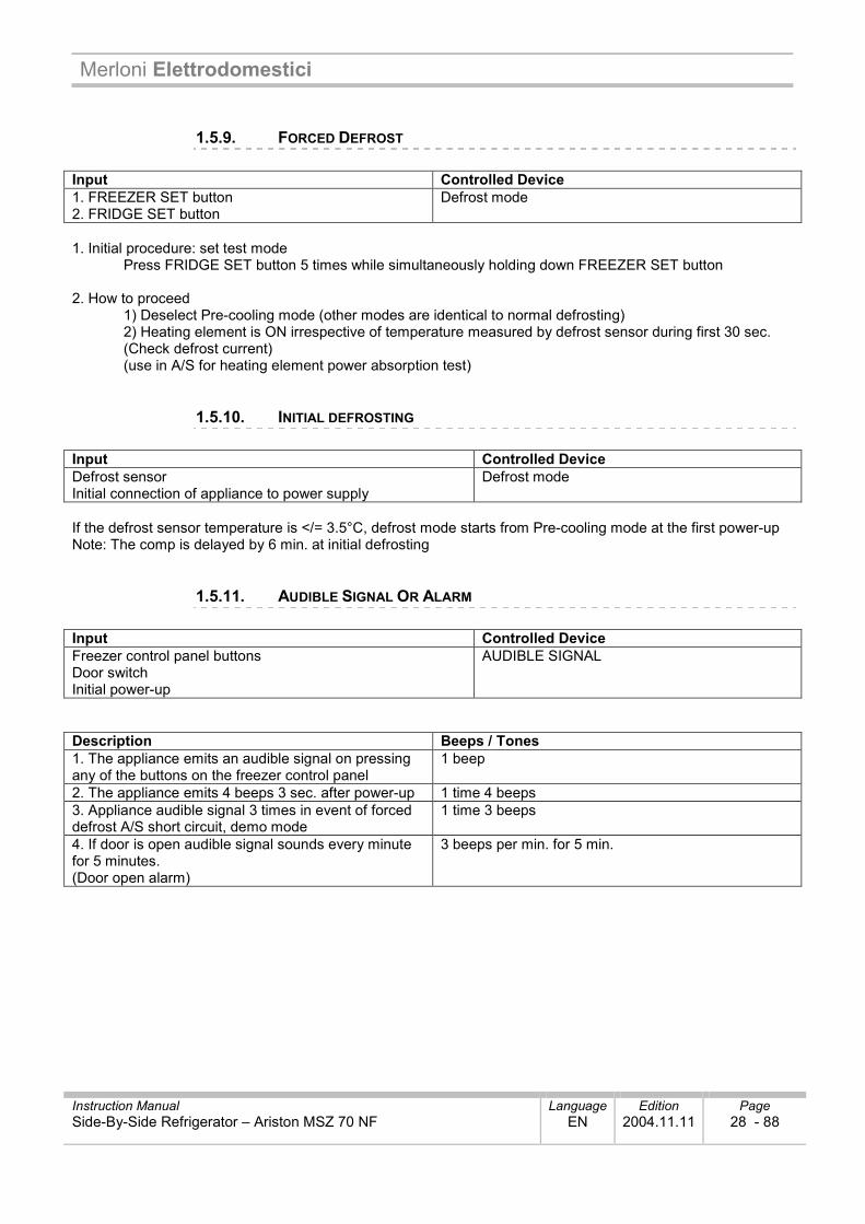
1.5.9. FORCED DEFROST Input Controlled Device 1. FREEZER SET button 2. FRIDGE SET button
Defrost mode
1. Initial procedure: set test mode
Press FRIDGE SET button 5 times while simultaneously holding down FREEZER SET button
2. How to proceed 1) Deselect Pre-cooling mode (other modes are identical to normal defrosting) 2) Heating element is ON irrespective of temperature measured by defrost sensor during first 30 sec. (Check defrost current) (use in A/S for heating element power absorption test)
1.5.10. INITIAL DEFROSTING Input Controlled Device Defrost sensor Initial connection of appliance to power supply
Defrost mode
If the defrost sensor temperature is </= 3.5°C, defrost mode starts from Pre-cooling mode at the first power-up Note: The comp is delayed by 6 min. at initial defrosting
1.5.11. AUDIBLE SIGNAL OR ALARM Input Controlled Device Freezer control panel buttons Door switch Initial power-up
AUDIBLE SIGNAL
Description Beeps / Tones 1. The appliance emits an audible signal on pressing any of the buttons on the freezer control panel
1 beep
2. The appliance emits 4 beeps 3 sec. after power-up 1 time 4 beeps 3. Appliance audible signal 3 times in event of forced defrost A/S short circuit, demo mode
1 time 3 beeps
4. If door is open audible signal sounds every minute for 5 minutes. (Door open alarm)
3 beeps per min. for 5 min.
Merloni Elettrodomestici
Instruction Manual Language Edition Page Side-By-Side Refrigerator – Ariston MSZ 70 NF EN 2004.11.11 29 - 88
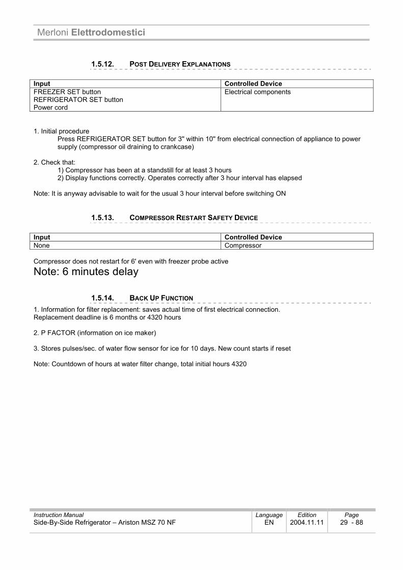
1.5.12. POST DELIVERY EXPLANATIONS Input Controlled Device FREEZER SET button REFRIGERATOR SET button Power cord
Electrical components
1. Initial procedure
Press REFRIGERATOR SET button for 3'' within 10'' from electrical connection of appliance to power supply (compressor oil draining to crankcase)
2. Check that:
1) Compressor has been at a standstill for at least 3 hours 2) Display functions correctly. Operates correctly after 3 hour interval has elapsed
Note: It is anyway advisable to wait for the usual 3 hour interval before switching ON
1.5.13. COMPRESSOR RESTART SAFETY DEVICE Input Controlled Device None Compressor Compressor does not restart for 6' even with freezer probe active
Note: 6 minutes delay
1.5.14. BACK UP FUNCTION 1. Information for filter replacement: saves actual time of first electrical connection. Replacement deadline is 6 months or 4320 hours 2. P FACTOR (information on ice maker) 3. Stores pulses/sec. of water flow sensor for ice for 10 days. New count starts if reset Note: Countdown of hours at water filter change, total initial hours 4320
Merloni Elettrodomestici
Instruction Manual Language Edition Page Side-By-Side Refrigerator – Ariston MSZ 70 NF EN 2004.11.11 30 - 88
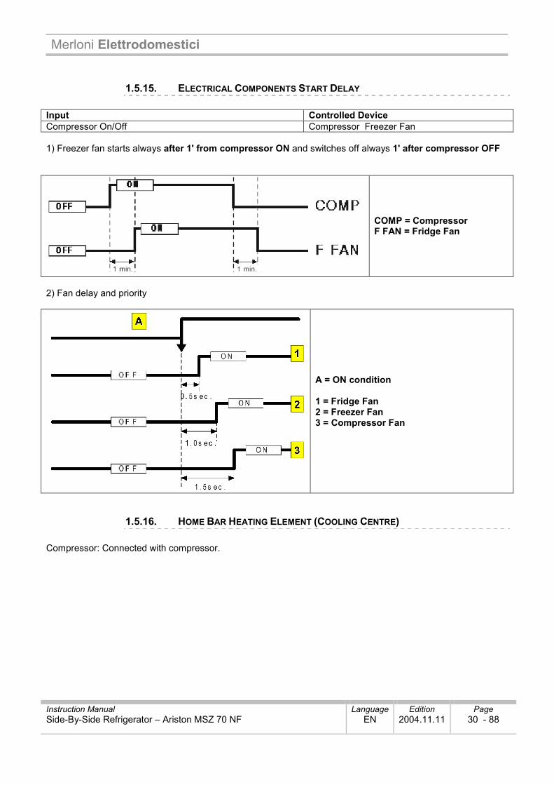
1.5.15. ELECTRICAL COMPONENTS START DELAY Input Controlled Device Compressor On/Off Compressor Freezer Fan 1) Freezer fan starts always after 1' from compressor ON and switches off always 1' after compressor OFF
COMP = Compressor F FAN = Fridge Fan
2) Fan delay and priority
A = ON condition 1 = Fridge Fan 2 = Freezer Fan 3 = Compressor Fan
1.5.16. HOME BAR HEATING ELEMENT (COOLING CENTRE) Compressor: Connected with compressor.
Merloni Elettrodomestici
Instruction Manual Language Edition Page Side-By-Side Refrigerator – Ariston MSZ 70 NF EN 2004.11.11 31 - 88
1.5.17. INTERIOR LIGHTS CONTROL Input Controlled Device Fridge door Freezer door Home Bar Door (Cooling Centre)
Light
1) Fridge interior lights control
Fridge lights switch On and Off in accordance with fridge door switch (ON/OFF). 10 min after detection of door opening lights switch off automatically even if door closing not detected
2) Freezer interior lights control
The freezer lights are activated by means of the freezer door switch (On / OFF) 10 min after detection of door opening, the lights switch off automatically even if door closing is not detected
3) The fridge lights switch On and Off with the opening / closing of the Home-Bar door
The fridge lights switch on for 10 min after detection of Home-Bar door opening (if the switch is pressed again for 1 min. the light switches on again for a further 10 minutes)
4) Dispenser lamp test
The dispenser lamp is switched On/Off by the dispenser switch The dispenser lamp switches On for 5 sec. after switch closing has been detected
1.5.18. DEMONSTRATION FUNCTION Input Controlled Device WATER/FRIDGE SET buttons Door switch
Compressor Freezer fan Fridge fan
1. Initial procedure
Press WATER button 5 times while simultaneously holding down FRIDGE SET button 2. Check
1) that all electrical components are deactivated except for the fridge/freezer fan. 2) Check the fan DOOR OPEN -> FAN ON
DOOR CLOSED -> FAN OFF
3. Stop or end 1) During demo mode, press the button 5 times while simultaneously holding down the FRIDGE SET button 2) Reconnect to the power supply
(can be used in Service for checking operation of the fans - also with the sensors disconnected)
Merloni Elettrodomestici
Instruction Manual Language Edition Page Side-By-Side Refrigerator – Ariston MSZ 70 NF EN 2004.11.11 32 - 88
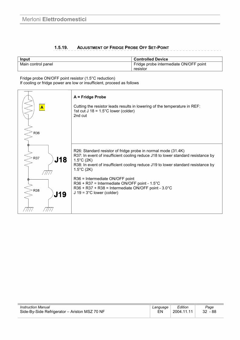
1.5.19. ADJUSTMENT OF FRIDGE PROBE OFF SET-POINT Input Controlled Device Main control panel Fridge probe intermediate ON/OFF point
resistor Fridge probe ON/OFF point resistor (1.5°C reduction) If cooling or fridge power are low or insufficient, proceed as follows
A = Fridge Probe Cutting the resistor leads results in lowering of the temperature in REF: 1st cut J 18 = 1.5°C lower (colder) 2nd cut
R26: Standard resistor of fridge probe in normal mode (31.4K) R37: In event of insufficient cooling reduce J18 to lower standard resistance by 1.5°C (2K) R38: In event of insufficient cooling reduce J19 to lower standard resistance by 1.5°C (2K) R36 = Intermediate ON/OFF point R36 + R37 = Intermediate ON/OFF point - 1.5°C R36 + R37 + R38 = Intermediate ON/OFF point - 3.0°C J 19 = 3°C lower (colder)
Merloni Elettrodomestici
Instruction Manual Language Edition Page Side-By-Side Refrigerator – Ariston MSZ 70 NF EN 2004.11.11 33 - 88
1.5.20. FUNCTIONS SUMMARY 1. Activation of functions for Service (activated directly) Forced defrost FREEZER SET + FRIDGE SET 5 times
Post Delivery Explanations Press RESET WATER FILTER and hold down for 3 sec. (restores to 4320 hours)
Water filter information reset FRIDGE SET button for 3 sec. (within 10") after first start-up
Demo mode FRIDGE SET + WATER button 5 times 2. Special functions (activated after setting TEST) - All modes are started with test mode Test Mode: Press CRUSHED ICE button 5 times while simultaneously holding down WATER button Pull Down FREEZER ST + FRIDGE SET + WATER 5 times
(NO Displ-Comp-Fan / Func ON / Plug) Errors display FREEZER SET + SUPER FREEZE 5 times, see list **
(like Ice Maker Test-Rotat, Full, Inser W, Stop) EEPROM reset WATER + RESET WATER FILTER 5 times Ice maker test WATER + CUBED ICE 5 times ** Power-on minutes -Temp.F- Temp DS- Temp.R- Temp RT- P (100..+RSet=dwn,+SR=up)--Fi Le (+ W = Remaining time from 4320 hours for water filter replacement) RESET x 2
Merloni Elettrodomestici
Instruction Manual Language Edition Page Side-By-Side Refrigerator – Ariston MSZ 70 NF EN 2004.11.11 34 - 88
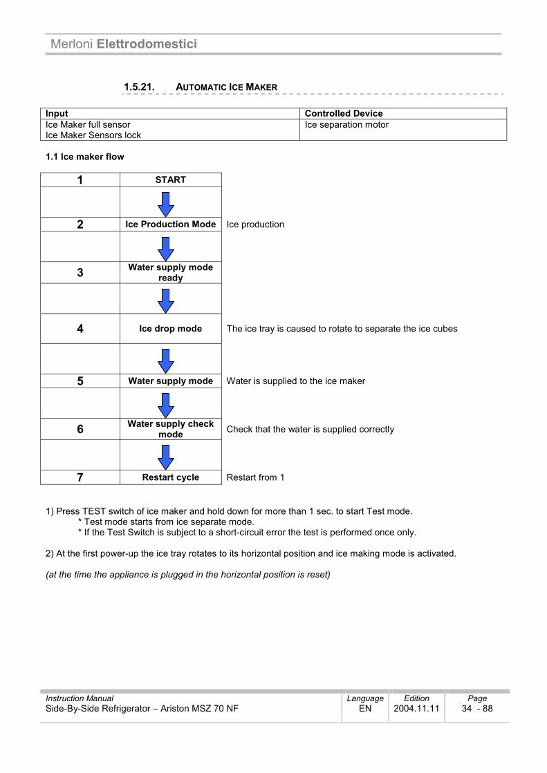
1.5.21. AUTOMATIC ICE MAKER Input Controlled Device Ice Maker full sensor Ice Maker Sensors lock
Ice separation motor
1.1 Ice maker flow
1 START
2 Ice Production Mode Ice production
3 Water supply mode ready
4 Ice drop mode The ice tray is caused to rotate to separate the ice cubes
5 Water supply mode Water is supplied to the ice maker
6 Water supply check mode Check that the water is supplied correctly
7 Restart cycle Restart from 1 1) Press TEST switch of ice maker and hold down for more than 1 sec. to start Test mode.
* Test mode starts from ice separate mode. * If the Test Switch is subject to a short-circuit error the test is performed once only.
2) At the first power-up the ice tray rotates to its horizontal position and ice making mode is activated. (at the time the appliance is plugged in the horizontal position is reset)
Merloni Elettrodomestici
Instruction Manual Language Edition Page Side-By-Side Refrigerator – Ariston MSZ 70 NF EN 2004.11.11 35 - 88
3) Water pipe heating element check
* The heating element is always ON if the room probe is in error of if TA (room temperature) is > 15°C. * The heating element is always ON for 60 min (max. time limit) if the Flow-sensor is subject to an error
(otherwise it is ON with the compressor) 4) Water supply ready mode
Condition: detection of ice maker full. Action: system proceeds with ice production mode (Ice drop and water supply mode are suspended). Process terminates in normal conditions.
5) Ice crushing function The function stops if the freezer door is open The function is active with the freezer door closed
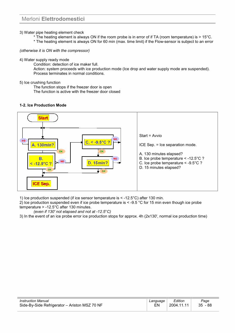
1-2. Ice Production Mode
Start = Avvio ICE Sep. = Ice separation mode. A. 130 minutes elapsed? B. Ice probe temperature < -12.5°C ? C. Ice probe temperature < -9.5°C ? D. 15 minutes elapsed?
1) Ice production suspended (if ice sensor temperature is < -12.5°C) after 130 min. 2) Ice production suspended even if ice probe temperature is < -9.5 °C for 15 min even though ice probe temperature > -12.5°C after 130 minutes.
(even if 130' not elapsed and not at -12.5°C) 3) In the event of an ice probe error ice production stops for approx. 4h (2x130', normal ice production time)
Merloni Elettrodomestici
Instruction Manual Language Edition Page Side-By-Side Refrigerator – Ariston MSZ 70 NF EN 2004.11.11 36 - 88
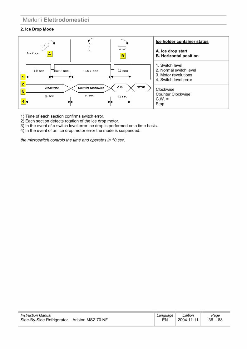
2. Ice Drop Mode
Ice holder container status A. Ice drop start B. Horizontal position
1. Switch level 2. Normal switch level 3. Motor revolutions 4. Switch level error
Clockwise Counter Clockwise C.W. = Stop
1) Time of each section confirms switch error. 2) Each section detects rotation of the ice drop motor. 3) In the event of a switch level error ice drop is performed on a time basis. 4) In the event of an ice drop motor error the mode is suspended. the microswitch controls the time and operates in 10 sec.
Merloni Elettrodomestici
Instruction Manual Language Edition Page Side-By-Side Refrigerator – Ariston MSZ 70 NF EN 2004.11.11 37 - 88
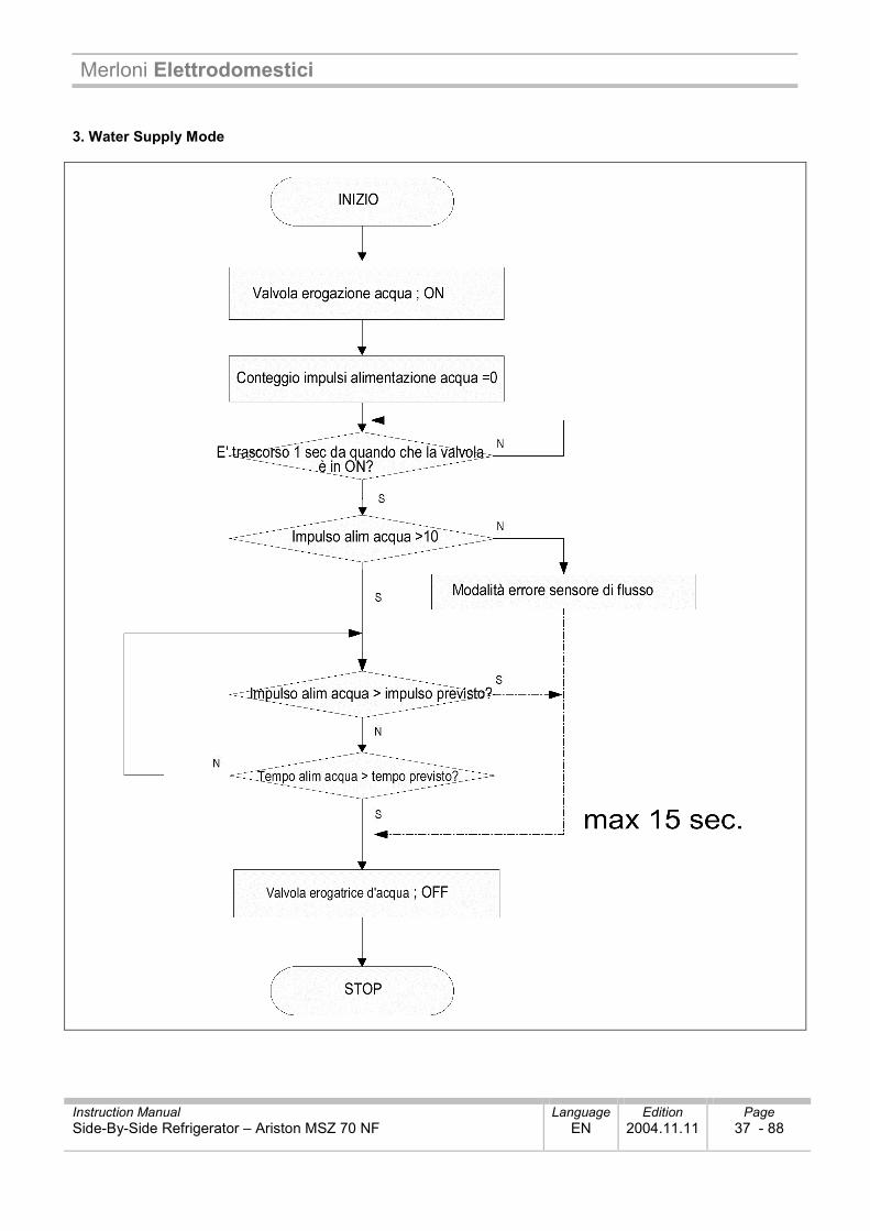
3. Water Supply Mode
Merloni Elettrodomestici
Instruction Manual Language Edition Page Side-By-Side Refrigerator – Ariston MSZ 70 NF EN 2004.11.11 38 - 88
1) The water supply valve is open when water supply mode starts after the ice drop. 2) Water supply is controlled on a time basis in the presence of a flow sensor error 3) The valve value is variable - this function is useful in AS action.
(see adjustment of A/S pulses **) ** adjustment P: W+Ice Crus. x 5 -> F Set + SF x 5 -> + R Set up, S R dwn 1 cc
-If water supply is on time basis, max. water supply time will be 15 sec. -If flow sensor functions correctly the flow pulse value stabilises at 238. -If the flow sensor is errored, the water supply time will be 5.5 sec. 238 = P100 = 86cc water
4. Water supply mode control
- 5 min after water supply status can be checked by the room probe and by the temperature increase of the ice probe
R-TS (NTC) 7°C ↓↓↓↓ ~13°C ~19°C ~29°C ~39°C 39°C ↑↑↑↑
I-S (Ice Sensor) -10°C ↑↑↑↑ -9°C ↑↑↑↑ -8°C ↑↑↑↑ -7°C ↑↑↑↑ -6°C ↑↑↑↑ -5°C ↑↑↑↑ IS measurement in °C, compared with TA °C, makes it possible to check whether or not water is present - E.g. frozen pipe
1.5.22. DISPENSER CONTROL FUNCTION Input Controlled Device Dispenser switch WATER / CUBED ICE / CRUSHED ICE buttons ICE MAKER LOCK button Freezer door switch
Dispenser indicator light Ice crusher motor Flap solenoid valve Ice crusher solenoid valve Dispenser water valve
1) Button to select WATER / CUBED ICE / CRUSHED ICE
(Sequence: Water --> Cubed Ice --> Crushed Ice) * Default mode: Water * The LED of the selected icon illuminates; the remaining LEDs remain extinguished.
2) Ice Maker Lock button
* The Icemaker Lock function and its LED are activated / deactivated when the button is pressed 3) Display
The Water LED switches on to indicate fault mode. The LED for each mode is switched on by pressing the corresponding button. (If the display switch develops an error during selection of a mode, the relative LED switches off) When the Icemaker Lock button is pressed:
- The Icemaker Lock function LED illuminates - If the Cubed Ice or Crushed Ice functions are selected the mode switches to Water and the Water mode LED illuminates - If another input is not generated after 1 hour from the time Cubed / Crushed Ice is selected, the mode reverts to Water.
Merloni Elettrodomestici
Instruction Manual Language Edition Page Side-By-Side Refrigerator – Ariston MSZ 70 NF EN 2004.11.11 39 - 88
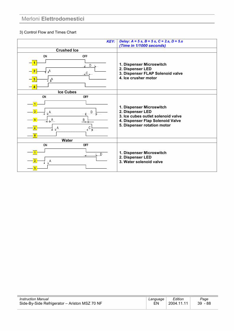
3) Control Flow and Times Chart
KEY:
Delay: A = 5 s, B = 5 s, C = 2.s, D = 5.s (Time in 1/1000 seconds)
Crushed Ice
1. Dispenser Microswitch 2. Dispenser LED 3. Dispenser FLAP Solenoid valve 4. Ice crusher motor
Ice Cubes
1. Dispenser Microswitch 2. Dispenser LED 3. Ice cubes outlet solenoid valve 4. Dispenser Flap Solenoid Valve 5. Dispenser rotation motor
Water
1. Dispenser Microswitch 2. Dispenser LED 3. Water solenoid valve
Merloni Elettrodomestici
Instruction Manual Language Edition Page Side-By-Side Refrigerator – Ariston MSZ 70 NF EN 2004.11.11 40 - 88
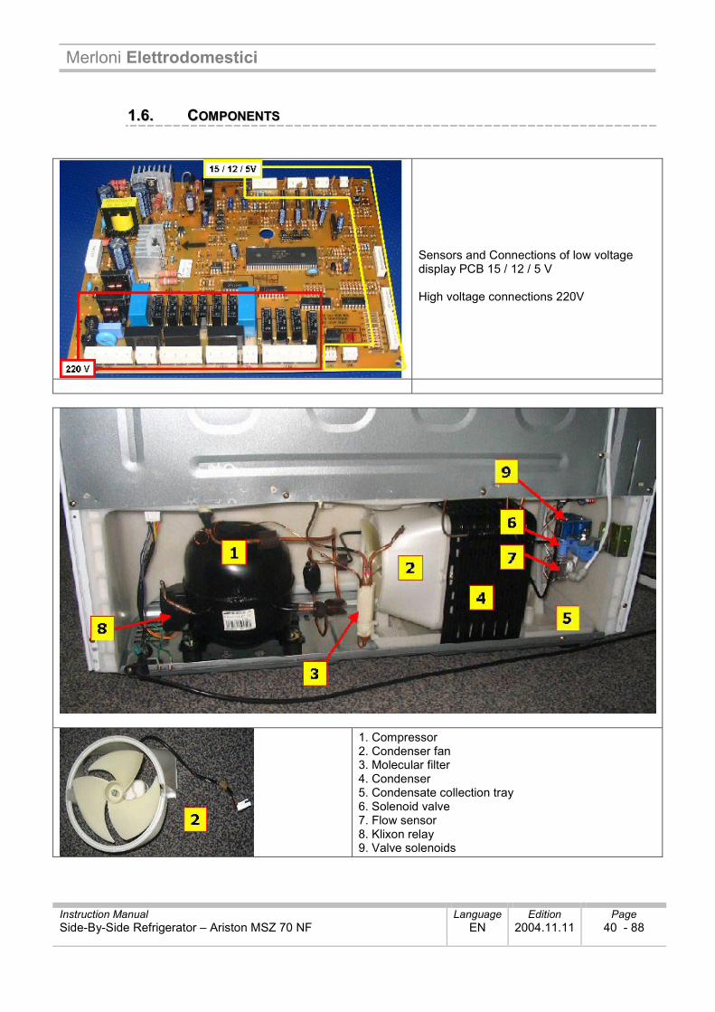
11..66.. CCOOMMPPOONNEENNTTSS
Sensors and Connections of low voltage display PCB 15 / 12 / 5 V High voltage connections 220V
1. Compressor 2. Condenser fan 3. Molecular filter 4. Condenser 5. Condensate collection tray 6. Solenoid valve 7. Flow sensor 8. Klixon relay 9. Valve solenoids
Merloni Elettrodomestici
Instruction Manual Language Edition Page Side-By-Side Refrigerator – Ariston MSZ 70 NF EN 2004.11.11 41 - 88
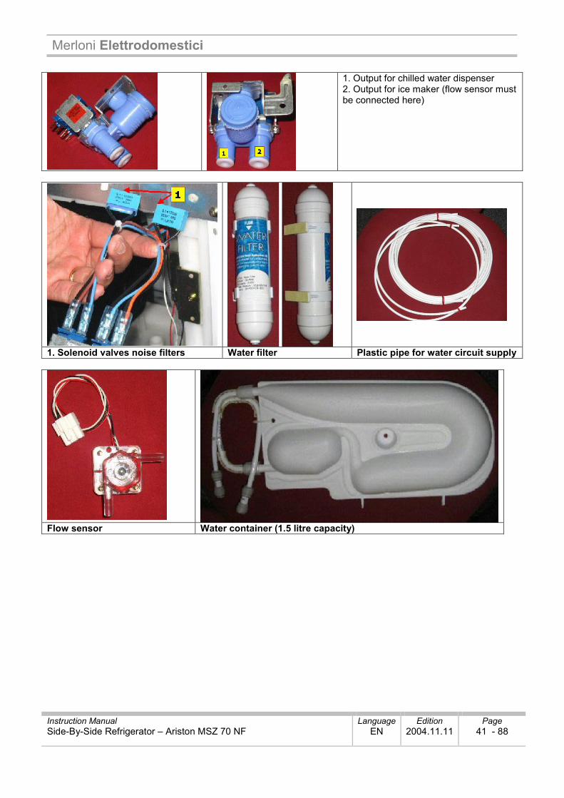
1. Output for chilled water dispenser 2. Output for ice maker (flow sensor must be connected here)
1. Solenoid valves noise filters Water filter Plastic pipe for water circuit supply
Flow sensor Water container (1.5 litre capacity)
Merloni Elettrodomestici
Instruction Manual Language Edition Page Side-By-Side Refrigerator – Ariston MSZ 70 NF EN 2004.11.11 42 - 88
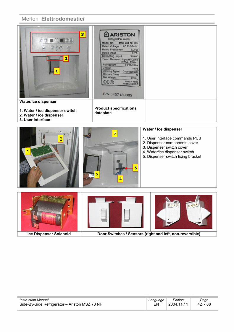
Water/Ice dispenser 1. Water / ice dispenser switch 2. Water / ice dispenser 3. User interface
Product specifications dataplate
Water / Ice dispenser 1. User interface commands PCB 2. Dispenser components cover 3. Dispenser switch cover 4. Water/ice dispenser switch 5. Dispenser switch fixing bracket
Ice Dispenser Solenoid Door Switches / Sensors (right and left, non-reversible)
Merloni Elettrodomestici
Instruction Manual Language Edition Page Side-By-Side Refrigerator – Ariston MSZ 70 NF EN 2004.11.11 43 - 88
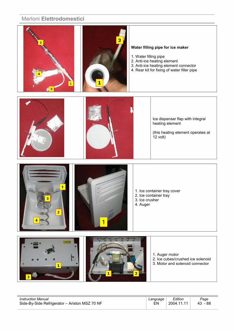
Water filling pipe for ice maker 1. Water filling pipe 2. Anti-ice heating element 3. Anti-ice heating element connector 4. Rear kit for fixing of water filler pipe
Ice dispenser flap with integral heating element (this heating element operates at 12 volt)
1. Ice container tray cover 2. Ice container tray 3. Ice crusher 4. Auger
1. Auger motor 2. Ice cubes/crushed ice solenoid 3. Motor and solenoid connector
Merloni Elettrodomestici
Instruction Manual Language Edition Page Side-By-Side Refrigerator – Ariston MSZ 70 NF EN 2004.11.11 44 - 88
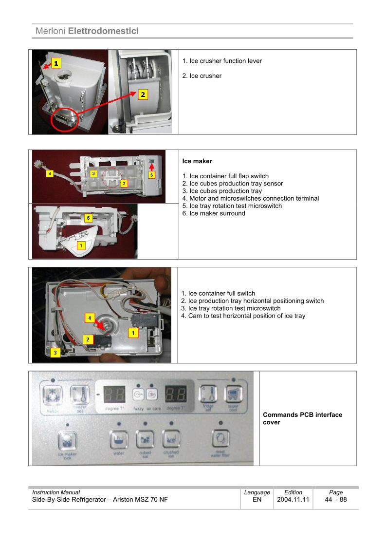
1. Ice crusher function lever 2. Ice crusher
Ice maker 1. Ice container full flap switch 2. Ice cubes production tray sensor 3. Ice cubes production tray 4. Motor and microswitches connection terminal 5. Ice tray rotation test microswitch 6. Ice maker surround
1. Ice container full switch 2. Ice production tray horizontal positioning switch 3. Ice tray rotation test microswitch 4. Cam to test horizontal position of ice tray
Commands PCB interface cover
Merloni Elettrodomestici
Instruction Manual Language Edition Page Side-By-Side Refrigerator – Ariston MSZ 70 NF EN 2004.11.11 45 - 88
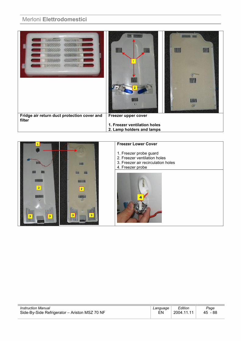
Fridge air return duct protection cover and filter
Freezer upper cover 1. Freezer ventilation holes 2. Lamp holders and lamps
Freezer Lower Cover 1. Freezer probe guard 2. Freezer ventilation holes 3. Freezer air recirculation holes 4. Freezer probe
Merloni Elettrodomestici
Instruction Manual Language Edition Page Side-By-Side Refrigerator – Ariston MSZ 70 NF EN 2004.11.11 46 - 88
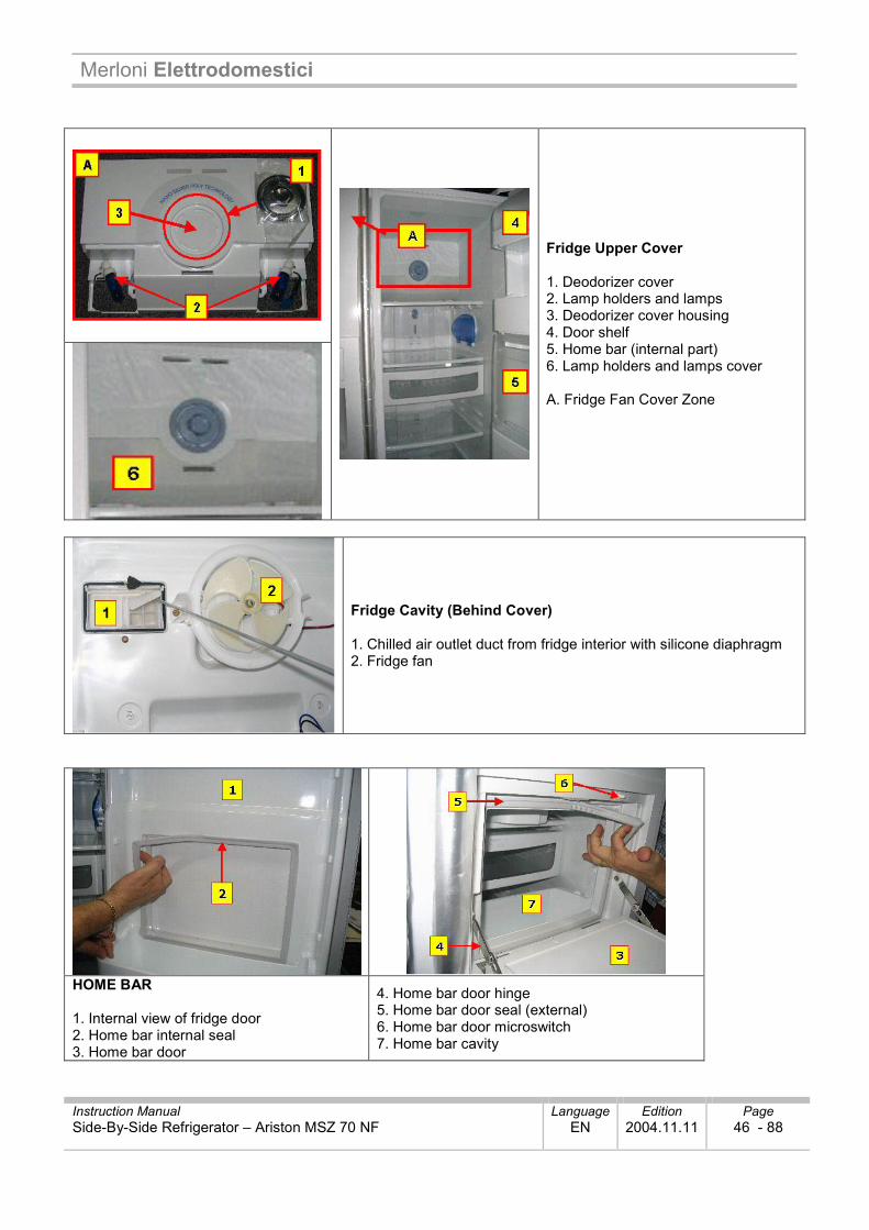
Fridge Upper Cover 1. Deodorizer cover 2. Lamp holders and lamps 3. Deodorizer cover housing 4. Door shelf 5. Home bar (internal part) 6. Lamp holders and lamps cover A. Fridge Fan Cover Zone
Fridge Cavity (Behind Cover) 1. Chilled air outlet duct from fridge interior with silicone diaphragm 2. Fridge fan
HOME BAR 1. Internal view of fridge door 2. Home bar internal seal 3. Home bar door
4. Home bar door hinge 5. Home bar door seal (external) 6. Home bar door microswitch 7. Home bar cavity
Merloni Elettrodomestici
Instruction Manual Language Edition Page Side-By-Side Refrigerator – Ariston MSZ 70 NF EN 2004.11.11 47 - 88
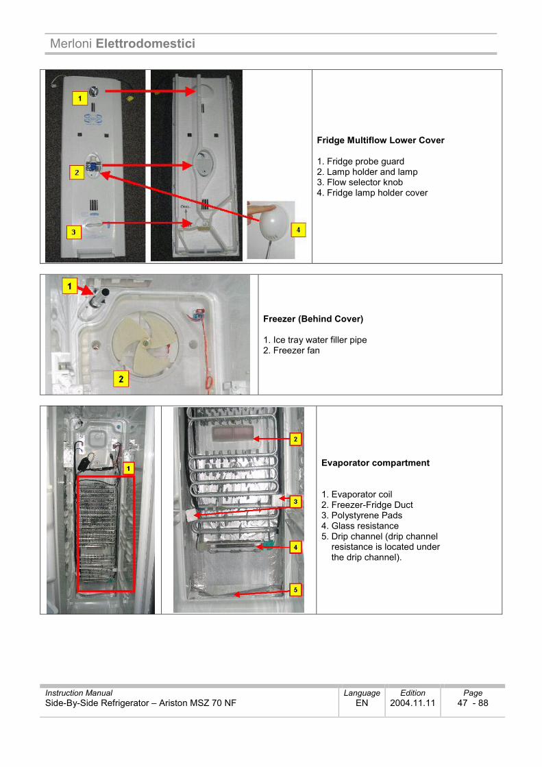
Fridge Multiflow Lower Cover 1. Fridge probe guard 2. Lamp holder and lamp 3. Flow selector knob 4. Fridge lamp holder cover
Freezer (Behind Cover) 1. Ice tray water filler pipe 2. Freezer fan
Evaporator compartment 1. Evaporator coil 2. Freezer-Fridge Duct 3. Polystyrene Pads 4. Glass resistance 5. Drip channel (drip channel resistance is located under the drip channel).
Merloni Elettrodomestici
Instruction Manual Language Edition Page Side-By-Side Refrigerator – Ariston MSZ 70 NF EN 2004.11.11 48 - 88
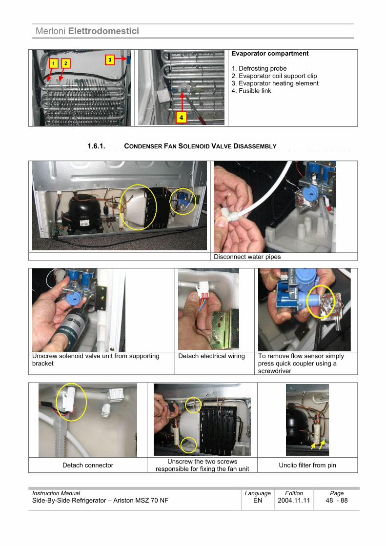
Evaporator compartment 1. Defrosting probe 2. Evaporator coil support clip 3. Evaporator heating element 4. Fusible link
1.6.1. CONDENSER FAN SOLENOID VALVE DISASSEMBLY
Disconnect water pipes
Unscrew solenoid valve unit from supporting bracket
Detach electrical wiring To remove flow sensor simply press quick coupler using a screwdriver
Detach connector Unscrew the two screws responsible for fixing the fan unit Unclip filter from pin
Merloni Elettrodomestici
Instruction Manual Language Edition Page Side-By-Side Refrigerator – Ariston MSZ 70 NF EN 2004.11.11 49 - 88
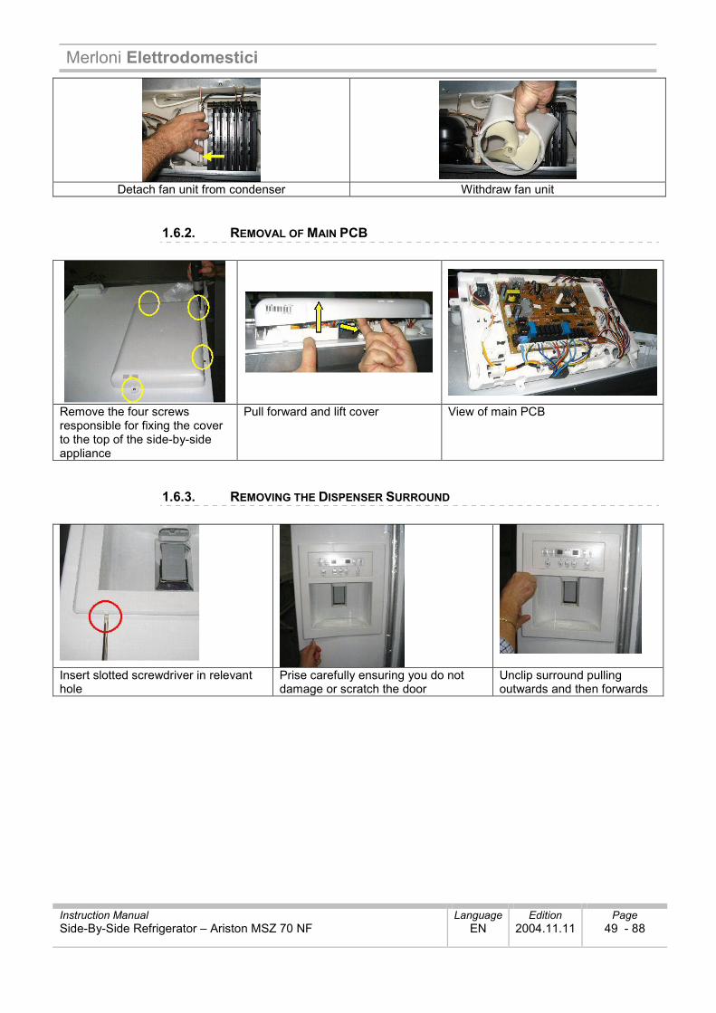
Detach fan unit from condenser Withdraw fan unit
1.6.2. REMOVAL OF MAIN PCB
Remove the four screws responsible for fixing the cover to the top of the side-by-side appliance
Pull forward and lift cover View of main PCB
1.6.3. REMOVING THE DISPENSER SURROUND
Insert slotted screwdriver in relevant hole
Prise carefully ensuring you do not damage or scratch the door
Unclip surround pulling outwards and then forwards
Merloni Elettrodomestici
Instruction Manual Language Edition Page Side-By-Side Refrigerator – Ariston MSZ 70 NF EN 2004.11.11 50 - 88
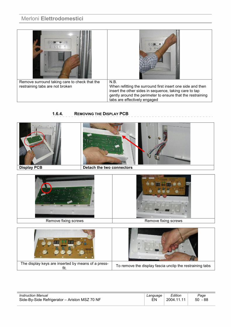
Remove surround taking care to check that the restraining tabs are not broken
N.B. When refitting the surround first insert one side and then insert the other sides in sequence, taking care to tap gently around the perimeter to ensure that the restraining tabs are effectively engaged
1.6.4. REMOVING THE DISPLAY PCB
Display PCB Detach the two connectors
Remove fixing screws Remove fixing screws
The display keys are inserted by means of a press-
fit. To remove the display fascia unclip the restraining tabs
Merloni Elettrodomestici
Instruction Manual Language Edition Page Side-By-Side Refrigerator – Ariston MSZ 70 NF EN 2004.11.11 51 - 88
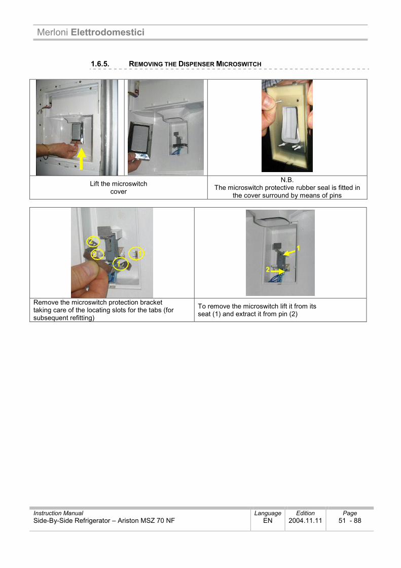
1.6.5. REMOVING THE DISPENSER MICROSWITCH
Lift the microswitch cover
N.B. The microswitch protective rubber seal is fitted in
the cover surround by means of pins
Remove the microswitch protection bracket taking care of the locating slots for the tabs (for subsequent refitting)
To remove the microswitch lift it from its seat (1) and extract it from pin (2)
Merloni Elettrodomestici
Instruction Manual Language Edition Page Side-By-Side Refrigerator – Ariston MSZ 70 NF EN 2004.11.11 52 - 88
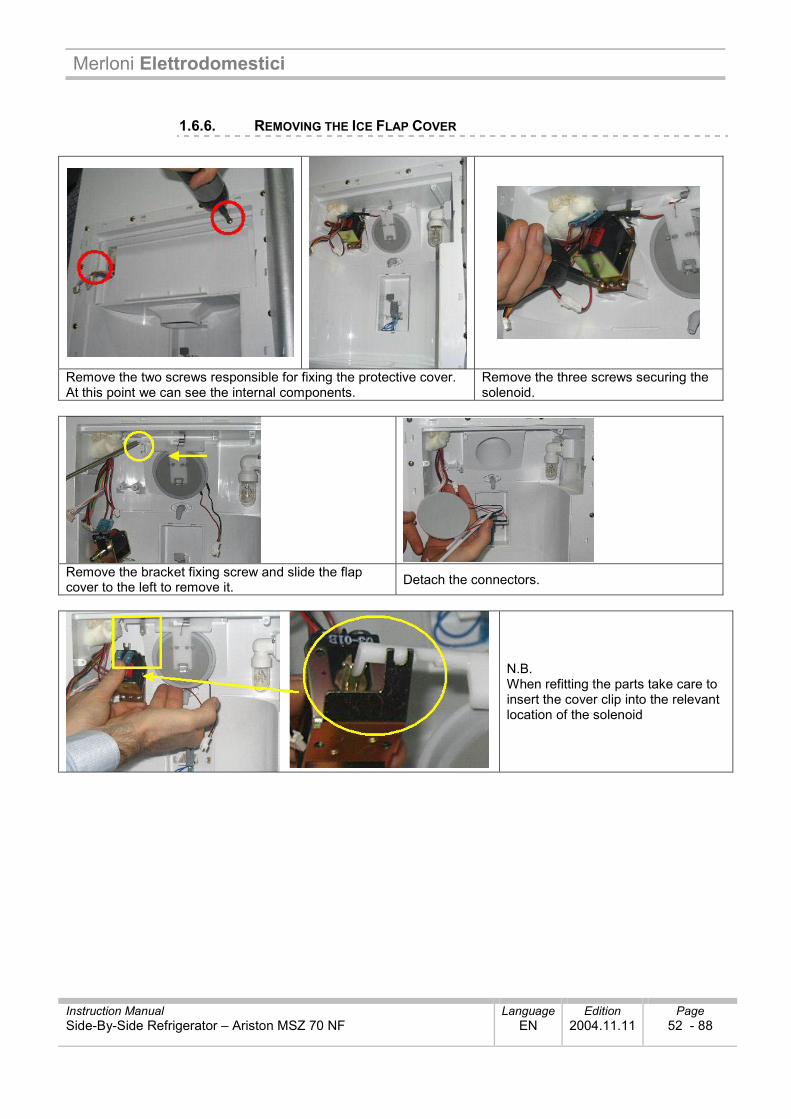
1.6.6. REMOVING THE ICE FLAP COVER
Remove the two screws responsible for fixing the protective cover. At this point we can see the internal components.
Remove the three screws securing the solenoid.
Remove the bracket fixing screw and slide the flap cover to the left to remove it. Detach the connectors.
N.B. When refitting the parts take care to insert the cover clip into the relevant location of the solenoid
Merloni Elettrodomestici
Instruction Manual Language Edition Page Side-By-Side Refrigerator – Ariston MSZ 70 NF EN 2004.11.11 53 - 88
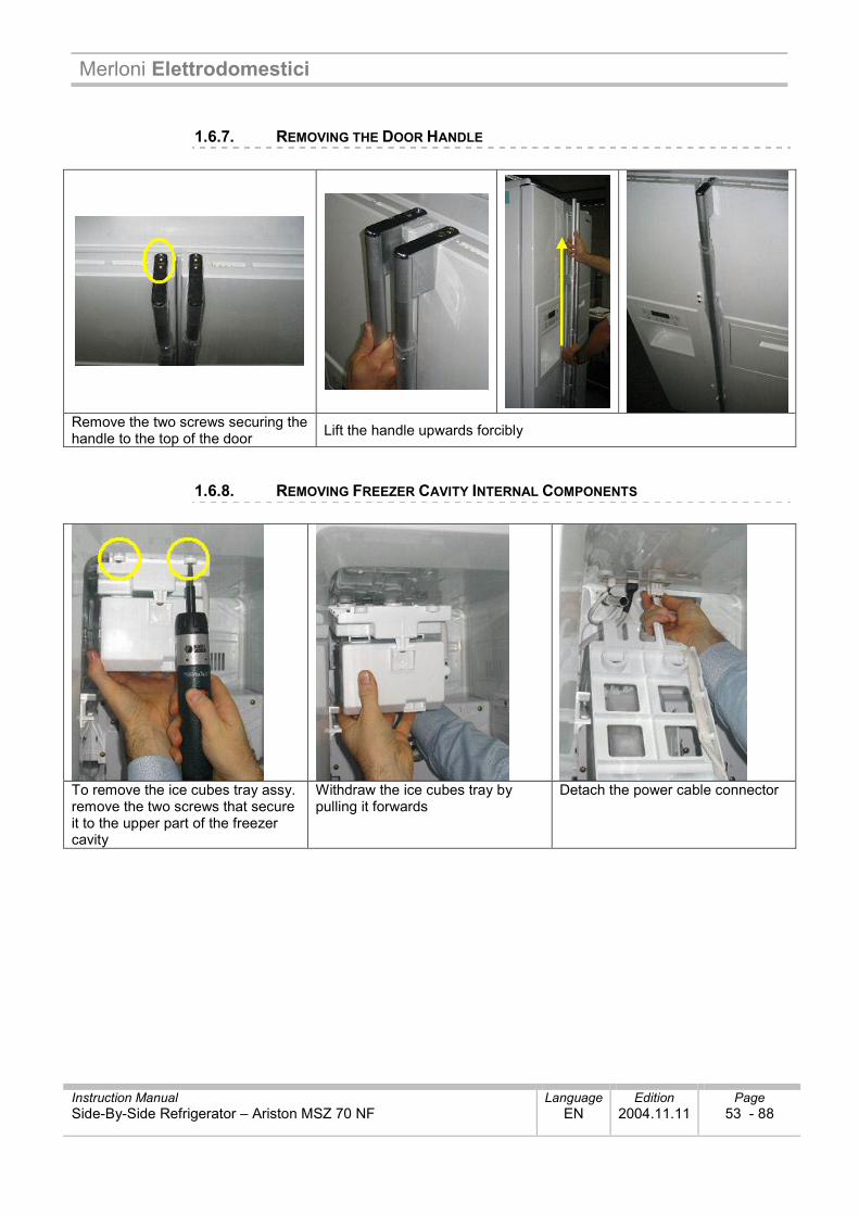
1.6.7. REMOVING THE DOOR HANDLE
Remove the two screws securing the handle to the top of the door Lift the handle upwards forcibly
1.6.8. REMOVING FREEZER CAVITY INTERNAL COMPONENTS
To remove the ice cubes tray assy. remove the two screws that secure it to the upper part of the freezer cavity
Withdraw the ice cubes tray by pulling it forwards
Detach the power cable connector
Merloni Elettrodomestici
Instruction Manual Language Edition Page Side-By-Side Refrigerator – Ariston MSZ 70 NF EN 2004.11.11 54 - 88
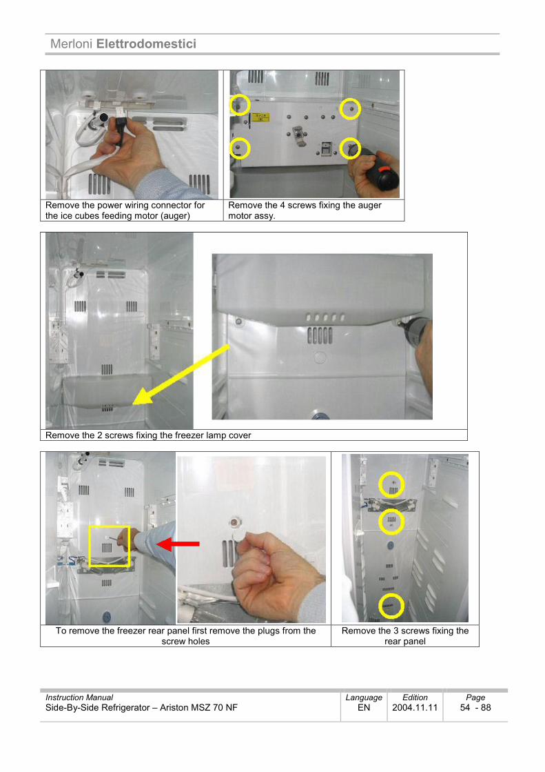
Remove the power wiring connector for the ice cubes feeding motor (auger)
Remove the 4 screws fixing the auger motor assy.
Remove the 2 screws fixing the freezer lamp cover
To remove the freezer rear panel first remove the plugs from the
screw holes Remove the 3 screws fixing the
rear panel
Merloni Elettrodomestici
Instruction Manual Language Edition Page Side-By-Side Refrigerator – Ariston MSZ 70 NF EN 2004.11.11 55 - 88
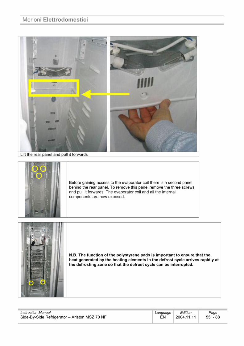
Lift the rear panel and pull it forwards
Before gaining access to the evaporator coil there is a second panel behind the rear panel. To remove this panel remove the three screws and pull it forwards. The evaporator coil and all the internal components are now exposed.
N.B. The function of the polystyrene pads is important to ensure that the heat generated by the heating elements in the defrost cycle arrives rapidly at the defrosting zone so that the defrost cycle can be interrupted.
Merloni Elettrodomestici
Instruction Manual Language Edition Page Side-By-Side Refrigerator – Ariston MSZ 70 NF EN 2004.11.11 56 - 88
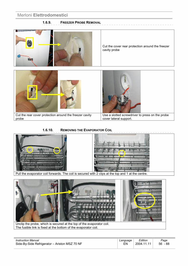
1.6.9. FREEZER PROBE REMOVAL
Cut the cover rear protection around the freezer cavity probe
Cut the rear cover protection around the freezer cavity probe
Use a slotted screwdriver to press on the probe cover lateral support.
1.6.10. REMOVING THE EVAPORATOR COIL
Pull the evaporator coil forwards. The coil is secured with 2 clips at the top and 1 at the centre.
Unclip the probe, which is secured at the top of the evaporator coil. The fusible link is fixed at the bottom of the evaporator coil.
Merloni Elettrodomestici
Instruction Manual Language Edition Page Side-By-Side Refrigerator – Ariston MSZ 70 NF EN 2004.11.11 57 - 88
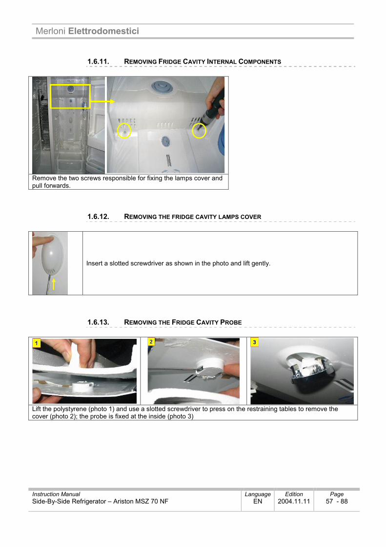
1.6.11. REMOVING FRIDGE CAVITY INTERNAL COMPONENTS
Remove the two screws responsible for fixing the lamps cover and pull forwards.
1.6.12. REMOVING THE FRIDGE CAVITY LAMPS COVER
Insert a slotted screwdriver as shown in the photo and lift gently.
1.6.13. REMOVING THE FRIDGE CAVITY PROBE
Lift the polystyrene (photo 1) and use a slotted screwdriver to press on the restraining tables to remove the cover (photo 2); the probe is fixed at the inside (photo 3)
Merloni Elettrodomestici
Instruction Manual Language Edition Page Side-By-Side Refrigerator – Ariston MSZ 70 NF EN 2004.11.11 58 - 88
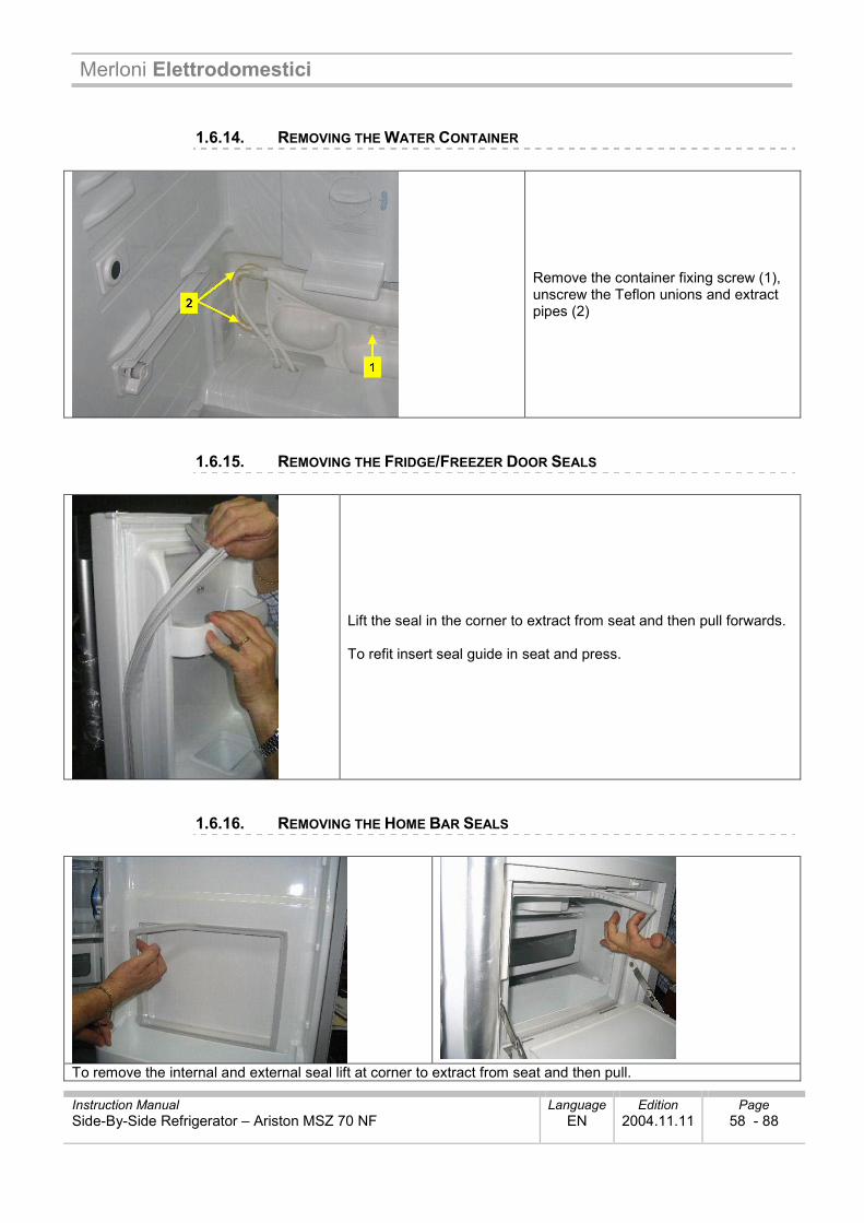
1.6.14. REMOVING THE WATER CONTAINER
Remove the container fixing screw (1), unscrew the Teflon unions and extract pipes (2)
1.6.15. REMOVING THE FRIDGE/FREEZER DOOR SEALS
Lift the seal in the corner to extract from seat and then pull forwards. To refit insert seal guide in seat and press.
1.6.16. REMOVING THE HOME BAR SEALS
To remove the internal and external seal lift at corner to extract from seat and then pull.
Merloni Elettrodomestici
Instruction Manual Language Edition Page Side-By-Side Refrigerator – Ariston MSZ 70 NF EN 2004.11.11 59 - 88
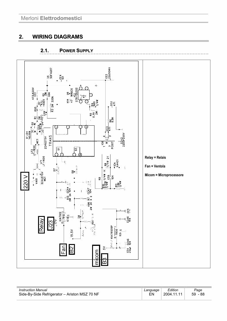
22.. WWIIRRIINNGG DDIIAAGGRRAAMMSS
22..11.. PPOOWWEERR SSUUPPPPLLYY
Relay = Relais Fan = Ventola Micom = Microprocessore

Merloni Elettrodomestici
Instruction Manual Language Edition Page Side-By-Side Refrigerator – Ariston MSZ 70 NF EN 2004.11.11 60 - 88
A. Fridge Probe B. Defrost Probe C. Freezer Probe D. Ice Maker
Probe
1. Fridge Probe 2. Defrost Probe 3. Freezer Probe
4. Ice Maker Probe 5. Ice drop motor
2.1.1. FUNCTIONS OF EACH PROBE Freezer Probe 1) Reads freezer cavity temperature and controls compressor and freezer fan ON-OFF 2) Functional description:
Operating set-point Connection temperature Mean Disconnection Temperature
High Disconnection Temperature
Working Temperature -13.0°C -21.0°C - 27.0°C
Probe Impedance ≒ 15.30k Ohm ≒ 23.83k Ohm ≒ 32.74k Ohm
Reading Voltage ≒ 3.14 V ≒ 2.60 V ≒ 2.20 V Defrost Probe Reads the defrost end temperature (condition at defrost end) Aim Deactivation of defrost heating element
Disconnection temperature 10°C
Probe impedance value ≒ 19.53k Ohm
Probe Voltage ≒ 3.1 V
Merloni Elettrodomestici
Instruction Manual Language Edition Page Side-By-Side Refrigerator – Ariston MSZ 70 NF EN 2004.11.11 61 - 88
Fridge Cavity Probe 1) Reads fridge cavity temperature and controls fridge fan ON-OFF 2) Functional description:
Operating set-point Connection temperature Mean Disconnection Temperature
High Disconnection Temperature
Working Temperature 4.3°C 1.3°C - 0.7°C
Probe Impedance ≒ 24.56k Ohm ≒ 27.95k Ohm ≒ 30.37k Ohm
Probe Voltage ≒ 2.82 V ≒ 2.66 V ≒ 2.55 V * If cooling of the fridge cavity is insufficient even though the compressor and fan are operating correctly
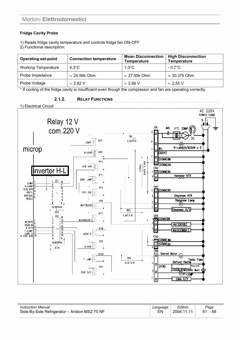
2.1.2. RELAY FUNCTIONS 1) Electrical Circuit
Merloni Elettrodomestici
Instruction Manual Language Edition Page Side-By-Side Refrigerator – Ariston MSZ 70 NF EN 2004.11.11 62 - 88
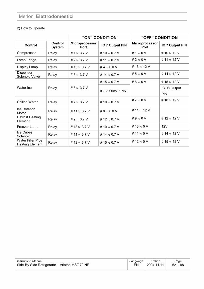
2) How to Operate
"ON" CONDITION "OFF" CONDITION
Control Control System
Microprocessor Port IC 7 Output PIN Microprocessor
Port IC 7 Output PIN
Compressor Relay # 1 ≒ 3.7 V # 10 ≒ 0.7 V # 1 ≒ 0 V # 10 ≒ 12 V
Lamp/Fridge Relay # 2 ≒ 3.7 V # 11 ≒ 0.7 V # 2 ≒ 0 V # 11 ≒ 12 V
Display Lamp Relay # 13 ≒ 0.7 V # 4 ≒ 0.0 V # 13 ≒ 12 V
Dispenser Solenoid Valve Relay # 5 ≒ 3.7 V # 14 ≒ 0.7 V # 5 ≒ 0 V # 14 ≒ 12 V
# 15 ≒ 0.7 V # 15 ≒ 12 V
Water Ice Relay # 6 ≒ 3.7 V IC 08 Output PIN
# 6 ≒ 0 V
IC 08 Output
PIN
Chilled Water Relay # 7 ≒ 3.7 V # 10 ≒ 0.7 V # 7 ≒ 0 V # 10 ≒ 12 V
Ice Rotation Motor Relay # 11 ≒ 0.7 V # 8 ≒ 0.0 V # 11 ≒ 12 V
Defrost Heating Element Relay # 9 ≒ 3.7 V # 12 ≒ 0.7 V # 9 ≒ 0 V # 12 ≒ 12 V
Freezer Lamp Relay # 13 ≒ 3.7 V # 10 ≒ 0.7 V # 13 ≒ 0 V 12V
Ice Cubes Solenoid Relay # 11 ≒ 3.7 V # 14 ≒ 0.7 V # 11 ≒ 0 V # 14 ≒ 12 V
Water Filler Pipe Heating Element Relay # 12 ≒ 3.7 V # 15 ≒ 0.7 V # 12 ≒ 0 V # 15 ≒ 12 V
Merloni Elettrodomestici
Instruction Manual Language Edition Page Side-By-Side Refrigerator – Ariston MSZ 70 NF EN 2004.11.11 63 - 88
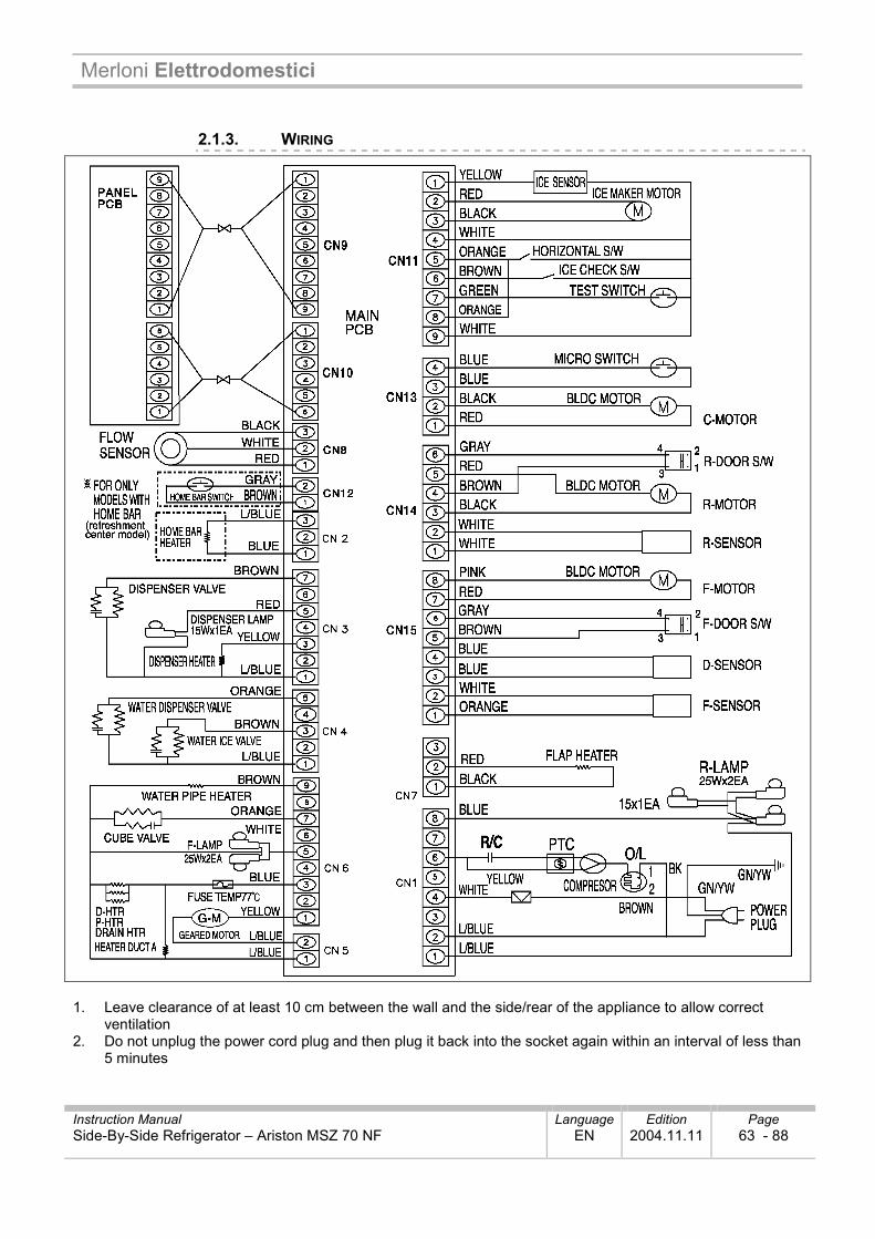
2.1.3. WIRING
1. Leave clearance of at least 10 cm between the wall and the side/rear of the appliance to allow correct
ventilation 2. Do not unplug the power cord plug and then plug it back into the socket again within an interval of less than
5 minutes
Merloni Elettrodomestici
Instruction Manual Language Edition Page Side-By-Side Refrigerator – Ariston MSZ 70 NF EN 2004.11.11 64 - 88
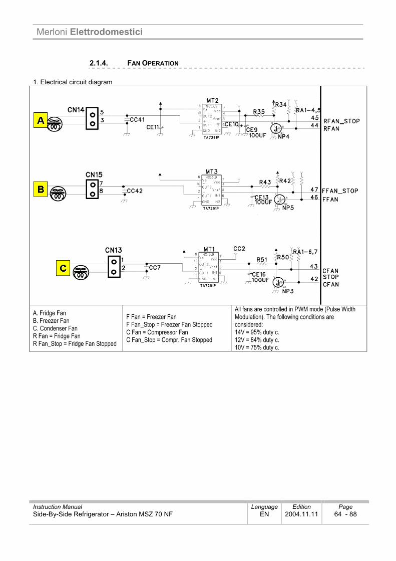
2.1.4. FAN OPERATION 1. Electrical circuit diagram
A. Fridge Fan B. Freezer Fan C. Condenser Fan R Fan = Fridge Fan R Fan_Stop = Fridge Fan Stopped
F Fan = Freezer Fan F Fan_Stop = Freezer Fan Stopped C Fan = Compressor Fan C Fan_Stop = Compr. Fan Stopped
All fans are controlled in PWM mode (Pulse Width Modulation). The following conditions are considered: 14V = 95% duty c. 12V = 84% duty c. 10V = 75% duty c.
Merloni Elettrodomestici
Instruction Manual Language Edition Page Side-By-Side Refrigerator – Ariston MSZ 70 NF EN 2004.11.11 65 - 88
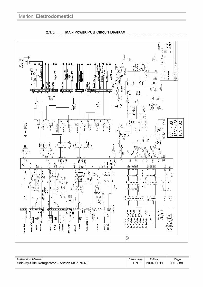
2.1.5. MAIN POWER PCB CIRCUIT DIAGRAM
Merloni Elettrodomestici
Instruction Manual Language Edition Page Side-By-Side Refrigerator – Ariston MSZ 70 NF EN 2004.11.11 66 - 88
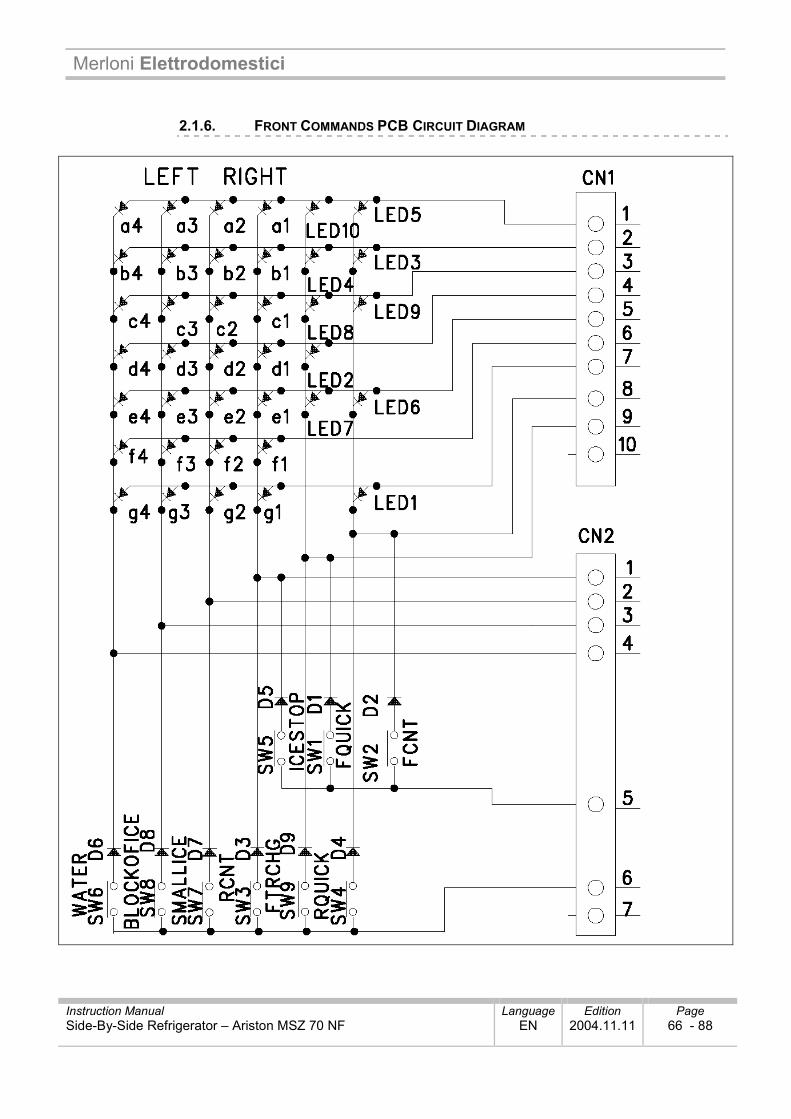
2.1.6. FRONT COMMANDS PCB CIRCUIT DIAGRAM
Merloni Elettrodomestici
Instruction Manual Language Edition Page Side-By-Side Refrigerator – Ariston MSZ 70 NF EN 2004.11.11 67 - 88
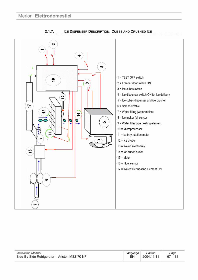
2.1.7. ICE DISPENSER DESCRIPTION: CUBES AND CRUSHED ICE
1 = TEST OFF switch 2 = Freezer door switch ON 3 = Ice cubes switch 4 = Ice dispenser switch ON for ice delivery 5 = Ice cubes dispenser and ice crusher 6 = Solenoid valve 7 = Water filling (water mains) 8 = Ice maker full sensor 9 = Water filler pipe heating element 10 = Microprocessor 11 =Ice tray rotation motor 12 = Ice probe 13 = Water inlet to tray 14 = Ice cubes outlet 15 = Motor 16 = Flow sensor 17 = Water filler heating element ON
Merloni Elettrodomestici
Instruction Manual Language Edition Page Side-By-Side Refrigerator – Ariston MSZ 70 NF EN 2004.11.11 68 - 88
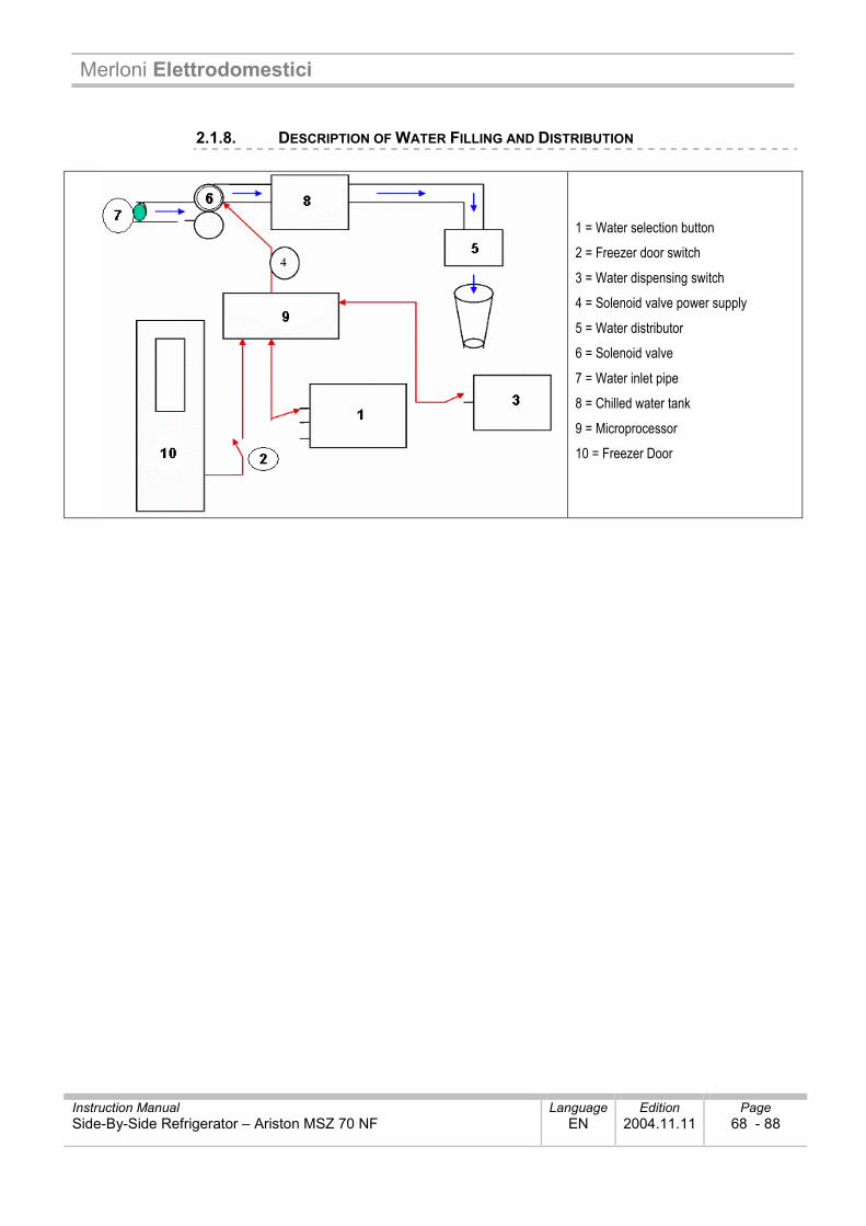
2.1.8. DESCRIPTION OF WATER FILLING AND DISTRIBUTION
1 = Water selection button 2 = Freezer door switch 3 = Water dispensing switch 4 = Solenoid valve power supply 5 = Water distributor 6 = Solenoid valve 7 = Water inlet pipe 8 = Chilled water tank 9 = Microprocessor 10 = Freezer Door
Merloni Elettrodomestici
Instruction Manual Language Edition Page Side-By-Side Refrigerator – Ariston MSZ 70 NF EN 2004.11.11 69 - 88
33.. AASSSSIISSTTAANNCCEE
33..11.. SSAAFFEETTYY AANNDD PPRREECCAAUUTTIIOONNSS
Carefully check to ensure there are not electrical ground faults or stray currents Handle electrical parts only when the appliance is unplugged from the mains socket outlet Avoid the risk of electrical shock by wearing rubber gloves when performing operating tests Before using any tools check nominal current, voltage, and capacity To avoid the risk of frostbite do not touch parts of the freezer with wet hands Adopt caution to ensure that water does not come into contact with electrical parts in the area of the
motor
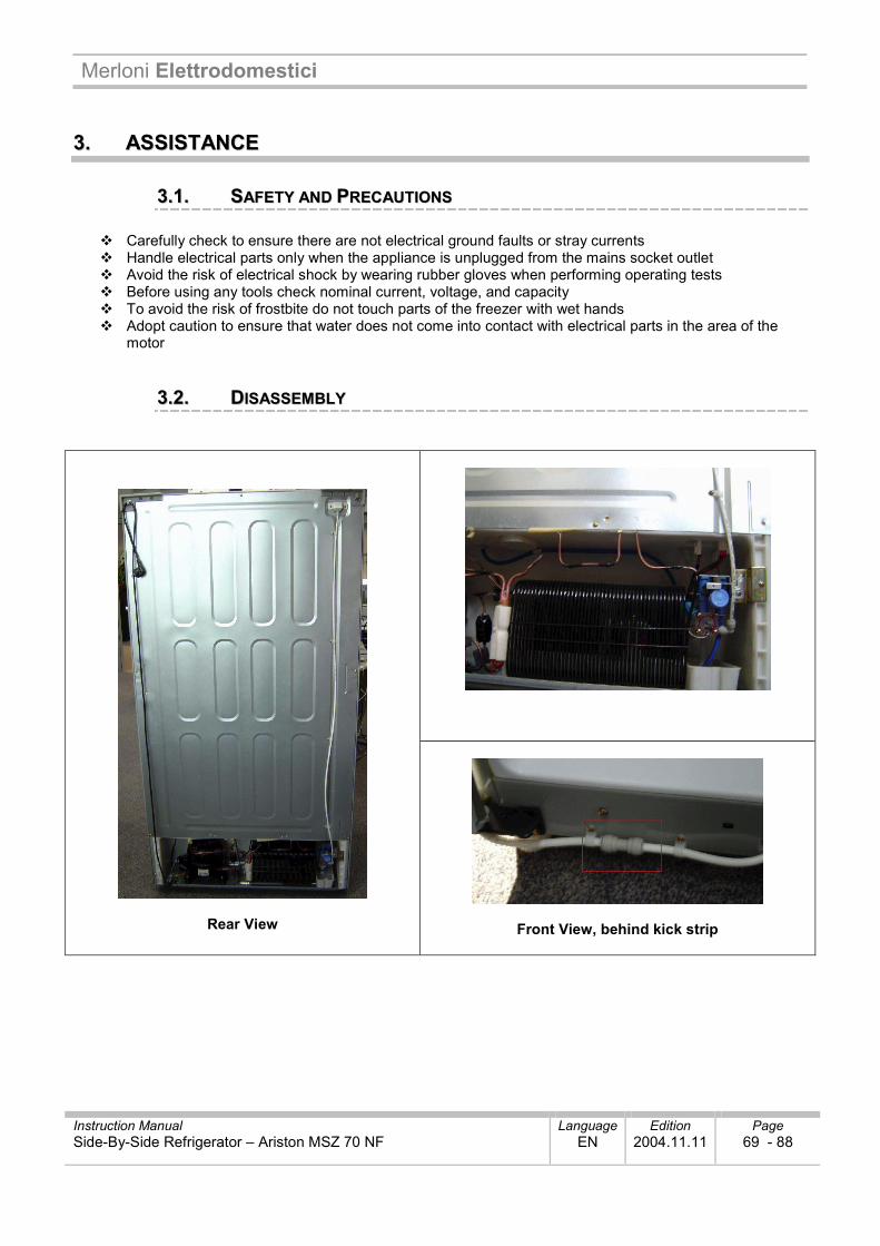
33..22.. DDIISSAASSSSEEMMBBLLYY
Rear View
Front View, behind kick strip
Merloni Elettrodomestici
Instruction Manual Language Edition Page Side-By-Side Refrigerator – Ariston MSZ 70 NF EN 2004.11.11 70 - 88
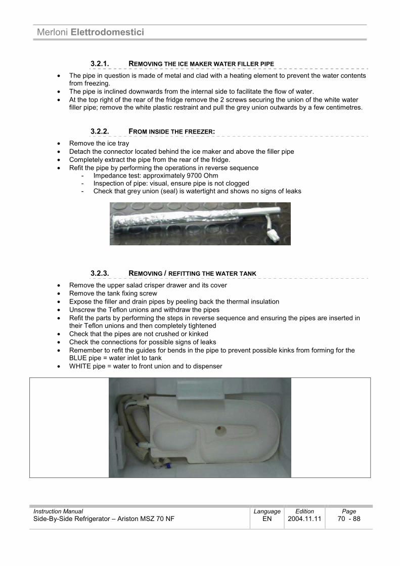
3.2.1. REMOVING THE ICE MAKER WATER FILLER PIPE • The pipe in question is made of metal and clad with a heating element to prevent the water contents
from freezing. • The pipe is inclined downwards from the internal side to facilitate the flow of water. • At the top right of the rear of the fridge remove the 2 screws securing the union of the white water
filler pipe; remove the white plastic restraint and pull the grey union outwards by a few centimetres.
3.2.2. FROM INSIDE THE FREEZER: • Remove the ice tray • Detach the connector located behind the ice maker and above the filler pipe • Completely extract the pipe from the rear of the fridge. • Refit the pipe by performing the operations in reverse sequence
- Impedance test: approximately 9700 Ohm - Inspection of pipe: visual, ensure pipe is not clogged - Check that grey union (seal) is watertight and shows no signs of leaks
3.2.3. REMOVING / REFITTING THE WATER TANK • Remove the upper salad crisper drawer and its cover • Remove the tank fixing screw • Expose the filler and drain pipes by peeling back the thermal insulation • Unscrew the Teflon unions and withdraw the pipes • Refit the parts by performing the steps in reverse sequence and ensuring the pipes are inserted in
their Teflon unions and then completely tightened • Check that the pipes are not crushed or kinked • Check the connections for possible signs of leaks • Remember to refit the guides for bends in the pipe to prevent possible kinks from forming for the
BLUE pipe = water inlet to tank • WHITE pipe = water to front union and to dispenser
Merloni Elettrodomestici
Instruction Manual Language Edition Page Side-By-Side Refrigerator – Ariston MSZ 70 NF EN 2004.11.11 71 - 88
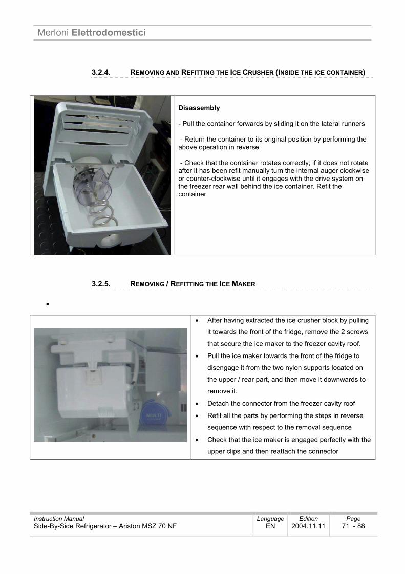
3.2.4. REMOVING AND REFITTING THE ICE CRUSHER (INSIDE THE ICE CONTAINER)
Disassembly - Pull the container forwards by sliding it on the lateral runners - Return the container to its original position by performing the above operation in reverse - Check that the container rotates correctly; if it does not rotate after it has been refit manually turn the internal auger clockwise or counter-clockwise until it engages with the drive system on the freezer rear wall behind the ice container. Refit the container
3.2.5. REMOVING / REFITTING THE ICE MAKER
•
• After having extracted the ice crusher block by pulling
it towards the front of the fridge, remove the 2 screws
that secure the ice maker to the freezer cavity roof.
• Pull the ice maker towards the front of the fridge to
disengage it from the two nylon supports located on
the upper / rear part, and then move it downwards to
remove it.
• Detach the connector from the freezer cavity roof
• Refit all the parts by performing the steps in reverse
sequence with respect to the removal sequence
• Check that the ice maker is engaged perfectly with the
upper clips and then reattach the connector
Merloni Elettrodomestici
Instruction Manual Language Edition Page Side-By-Side Refrigerator – Ariston MSZ 70 NF EN 2004.11.11 72 - 88
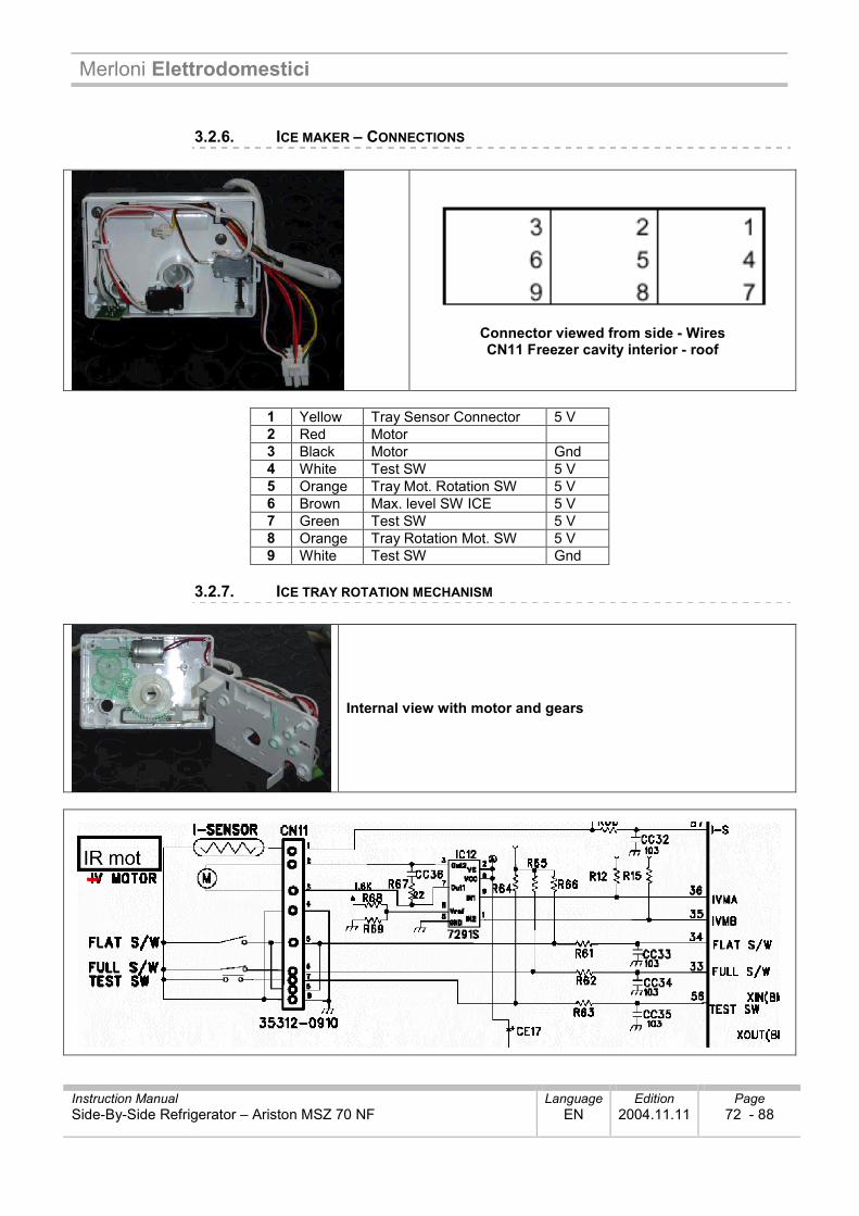
3.2.6. ICE MAKER – CONNECTIONS
Connector viewed from side - Wires CN11 Freezer cavity interior - roof
1 Yellow Tray Sensor Connector 5 V 2 Red Motor 3 Black Motor Gnd 4 White Test SW 5 V 5 Orange Tray Mot. Rotation SW 5 V 6 Brown Max. level SW ICE 5 V 7 Green Test SW 5 V 8 Orange Tray Rotation Mot. SW 5 V 9 White Test SW Gnd
3.2.7. ICE TRAY ROTATION MECHANISM
Internal view with motor and gears
Merloni Elettrodomestici
Instruction Manual Language Edition Page Side-By-Side Refrigerator – Ariston MSZ 70 NF EN 2004.11.11 73 - 88
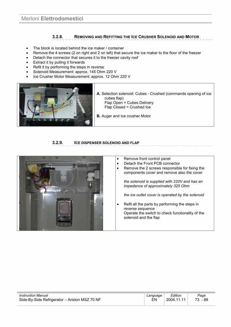
3.2.8. REMOVING AND REFITTING THE ICE CRUSHER SOLENOID AND MOTOR
• The block is located behind the ice maker / container • Remove the 4 screws (2 on right and 2 on left) that secure the ice maker to the floor of the freezer • Detach the connector that secures it to the freezer cavity roof • Extract it by pulling it forwards • Refit it by performing the steps in reverse • Solenoid Measurement: approx. 145 Ohm 220 V • Ice Crusher Motor Measurement: approx. 12 Ohm 220 V
A. Selection solenoid: Cubes - Crushed (commands opening of ice cubes flap)
Flap Open = Cubes Delivery Flap Closed = Crushed Ice B. Auger and Ice crusher Motor
3.2.9. ICE DISPENSER SOLENOID AND FLAP
• Remove front control panel • Detach the Front PCB connector • Remove the 2 screws responsible for fixing the
components cover and remove also the cover the solenoid is supplied with 220V and has an impedance of approximately 325 Ohm the ice outlet cover is operated by the solenoid
• Refit all the parts by performing the steps in reverse sequence Operate the switch to check functionality of the solenoid and the flap
Merloni Elettrodomestici
Instruction Manual Language Edition Page Side-By-Side Refrigerator – Ariston MSZ 70 NF EN 2004.11.11 74 - 88
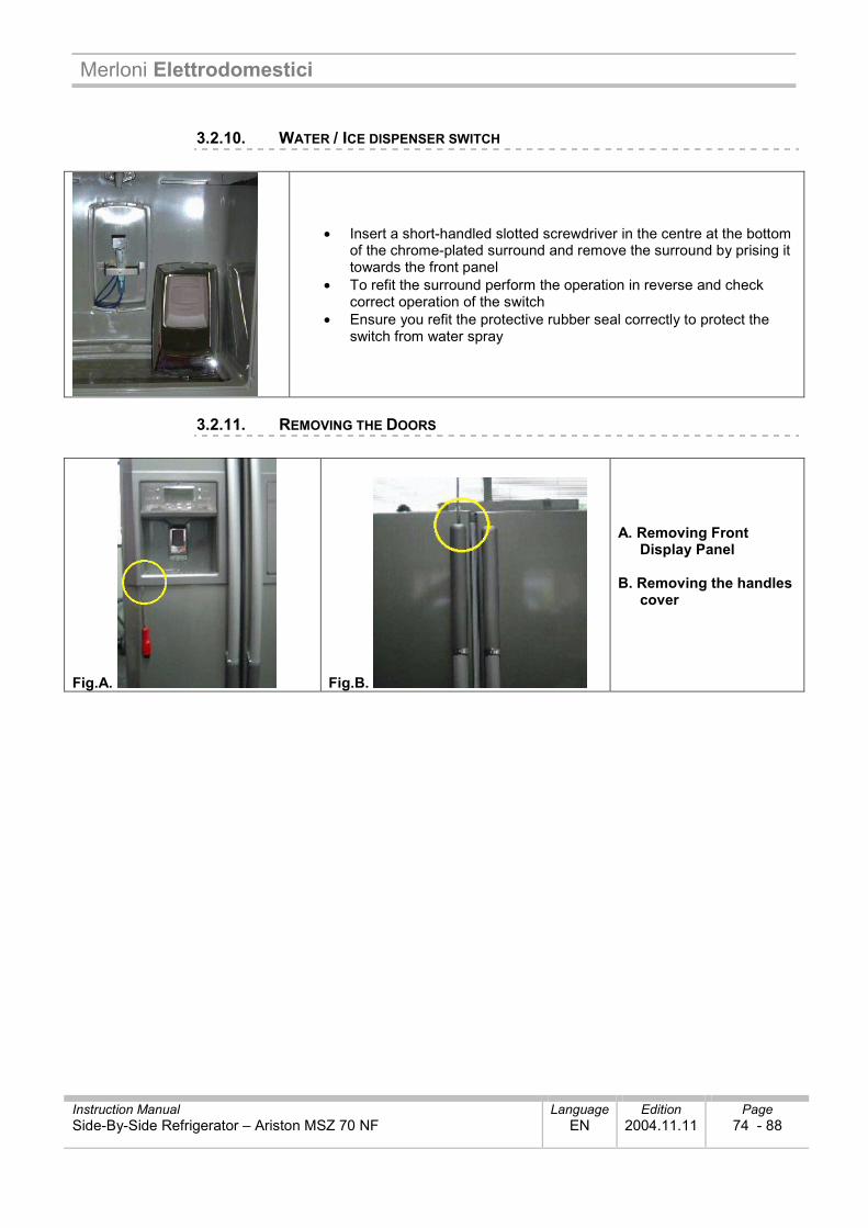
3.2.10. WATER / ICE DISPENSER SWITCH
• Insert a short-handled slotted screwdriver in the centre at the bottom of the chrome-plated surround and remove the surround by prising it towards the front panel
• To refit the surround perform the operation in reverse and check correct operation of the switch
• Ensure you refit the protective rubber seal correctly to protect the switch from water spray
3.2.11. REMOVING THE DOORS
Fig.A. Fig.B.
A. Removing Front Display Panel
B. Removing the handles
cover
Merloni Elettrodomestici
Instruction Manual Language Edition Page Side-By-Side Refrigerator – Ariston MSZ 70 NF EN 2004.11.11 75 - 88
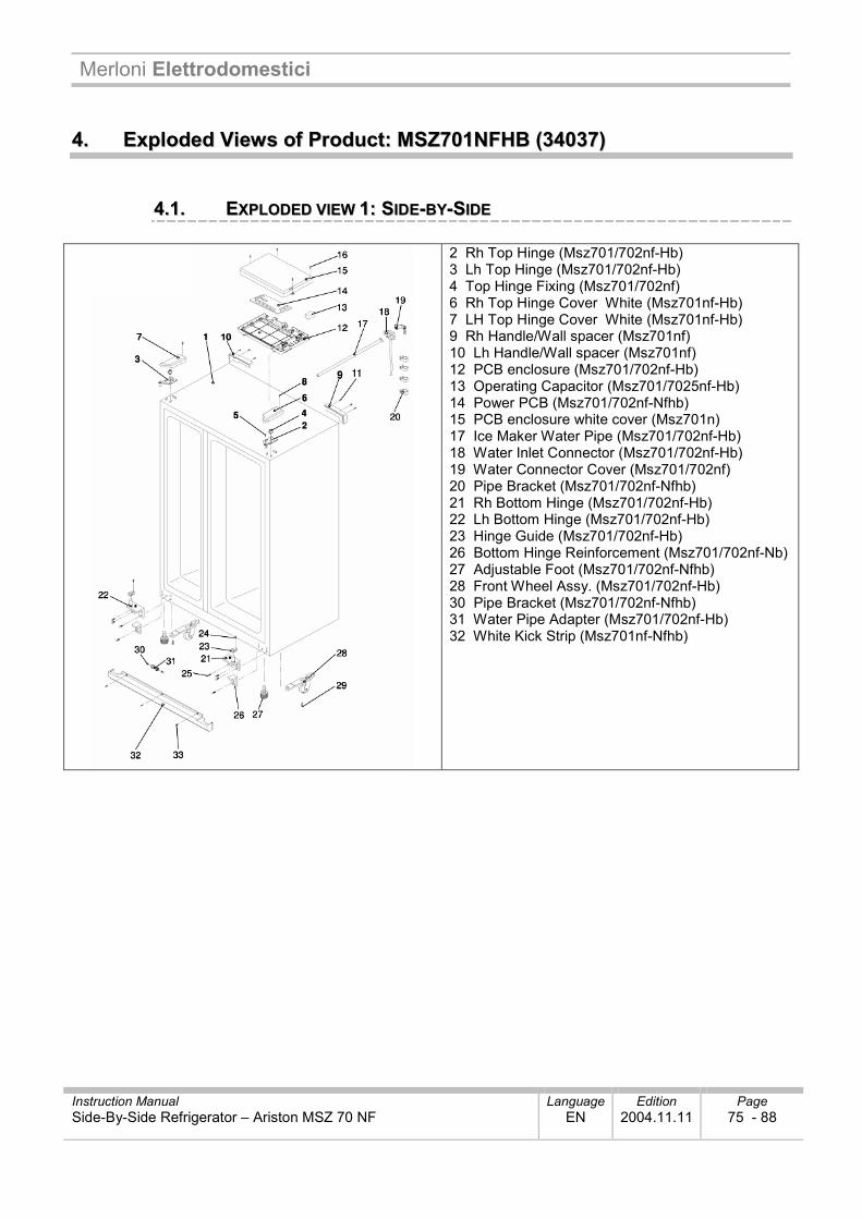
44.. EExxppllooddeedd VViieewwss ooff PPrroodduucctt:: MMSSZZ770011NNFFHHBB ((3344003377))
44..11.. EEXXPPLLOODDEEDD VVIIEEWW 11:: SSIIDDEE--BBYY--SSIIDDEE
2 Rh Top Hinge (Msz701/702nf-Hb) 3 Lh Top Hinge (Msz701/702nf-Hb) 4 Top Hinge Fixing (Msz701/702nf) 6 Rh Top Hinge Cover White (Msz701nf-Hb) 7 LH Top Hinge Cover White (Msz701nf-Hb) 9 Rh Handle/Wall spacer (Msz701nf) 10 Lh Handle/Wall spacer (Msz701nf) 12 PCB enclosure (Msz701/702nf-Hb) 13 Operating Capacitor (Msz701/7025nf-Hb) 14 Power PCB (Msz701/702nf-Nfhb) 15 PCB enclosure white cover (Msz701n) 17 Ice Maker Water Pipe (Msz701/702nf-Hb) 18 Water Inlet Connector (Msz701/702nf-Hb) 19 Water Connector Cover (Msz701/702nf) 20 Pipe Bracket (Msz701/702nf-Nfhb) 21 Rh Bottom Hinge (Msz701/702nf-Hb) 22 Lh Bottom Hinge (Msz701/702nf-Hb) 23 Hinge Guide (Msz701/702nf-Hb) 26 Bottom Hinge Reinforcement (Msz701/702nf-Nb) 27 Adjustable Foot (Msz701/702nf-Nfhb) 28 Front Wheel Assy. (Msz701/702nf-Hb) 30 Pipe Bracket (Msz701/702nf-Nfhb) 31 Water Pipe Adapter (Msz701/702nf-Hb) 32 White Kick Strip (Msz701nf-Nfhb)
Merloni Elettrodomestici
Instruction Manual Language Edition Page Side-By-Side Refrigerator – Ariston MSZ 70 NF EN 2004.11.11 76 - 88
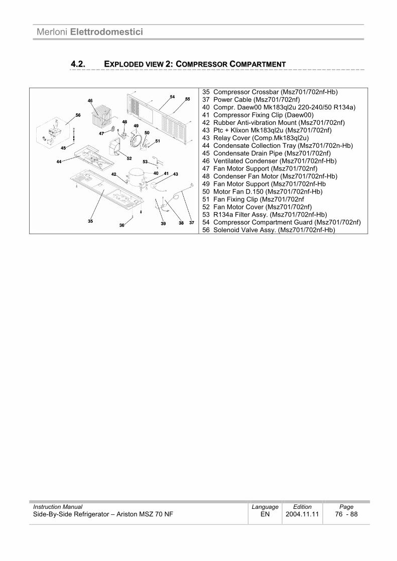
44..22.. EEXXPPLLOODDEEDD VVIIEEWW 22:: CCOOMMPPRREESSSSOORR CCOOMMPPAARRTTMMEENNTT
35 Compressor Crossbar (Msz701/702nf-Hb) 37 Power Cable (Msz701/702nf) 40 Compr. Daew00 Mk183ql2u 220-240/50 R134a) 41 Compressor Fixing Clip (Daew00) 42 Rubber Anti-vibration Mount (Msz701/702nf) 43 Ptc + Klixon Mk183ql2u (Msz701/702nf) 43 Relay Cover (Comp.Mk183ql2u) 44 Condensate Collection Tray (Msz701/702n-Hb) 45 Condensate Drain Pipe (Msz701/702nf) 46 Ventilated Condenser (Msz701/702nf-Hb) 47 Fan Motor Support (Msz701/702nf) 48 Condenser Fan Motor (Msz701/702nf-Hb) 49 Fan Motor Support (Msz701/702nf-Hb 50 Motor Fan D.150 (Msz701/702nf-Hb) 51 Fan Fixing Clip (Msz701/702nf 52 Fan Motor Cover (Msz701/702nf) 53 R134a Filter Assy. (Msz701/702nf-Hb) 54 Compressor Compartment Guard (Msz701/702nf) 56 Solenoid Valve Assy. (Msz701/702nf-Hb)
Merloni Elettrodomestici
Instruction Manual Language Edition Page Side-By-Side Refrigerator – Ariston MSZ 70 NF EN 2004.11.11 77 - 88
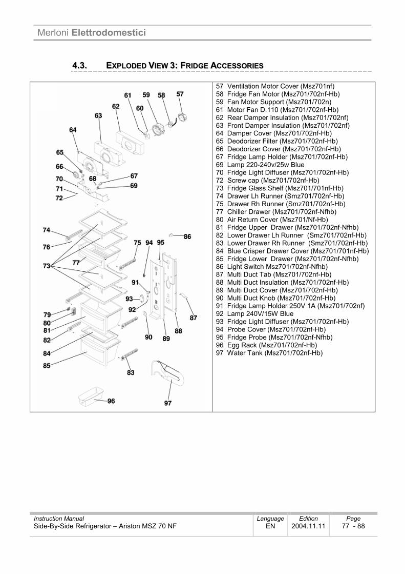
44..33.. EEXXPPLLOODDEEDD VVIIEEWW 33:: FFRRIIDDGGEE AACCCCEESSSSOORRIIEESS
57 Ventilation Motor Cover (Msz701nf) 58 Fridge Fan Motor (Msz701/702nf-Hb) 59 Fan Motor Support (Msz701/702n) 61 Motor Fan D.110 (Msz701/702nf-Hb) 62 Rear Damper Insulation (Msz701/702nf) 63 Front Damper Insulation (Msz701/702nf) 64 Damper Cover (Msz701/702nf-Hb) 65 Deodorizer Filter (Msz701/702nf-Hb) 66 Deodorizer Cover (Msz701/702nf-Hb) 67 Fridge Lamp Holder (Msz701/702nf-Hb) 69 Lamp 220-240v/25w Blue 70 Fridge Light Diffuser (Msz701/702nf-Hb) 72 Screw cap (Msz701/702nf-Hb) 73 Fridge Glass Shelf (Msz701/701nf-Hb) 74 Drawer Lh Runner (Smz701/702nf-Hb) 75 Drawer Rh Runner (Smz701/702nf-Hb) 77 Chiller Drawer (Msz701/702nf-Nfhb) 80 Air Return Cover (Msz701/Nf-Hb) 81 Fridge Upper Drawer (Msz701/702nf-Nfhb) 82 Lower Drawer Lh Runner (Smz701/702nf-Hb) 83 Lower Drawer Rh Runner (Smz701/702nf-Hb) 84 Blue Crisper Drawer Cover (Msz701/701nf-Hb) 85 Fridge Lower Drawer (Msz701/702nf-Nfhb) 86 Light Switch Msz701/702nf-Nfhb) 87 Multi Duct Tab (Msz701/702nf-Hb) 88 Multi Duct Insulation (Msz701/702nf-Hb) 89 Multi Duct Cover (Msz701/702nf-Hb) 90 Multi Duct Knob (Msz701/702nf-Hb) 91 Fridge Lamp Holder 250V 1A (Msz701/702nf) 92 Lamp 240V/15W Blue 93 Fridge Light Diffuser (Msz701/702nf-Hb) 94 Probe Cover (Msz701/702nf-Hb) 95 Fridge Probe (Msz701/702nf-Nfhb) 96 Egg Rack (Msz701/702nf-Hb) 97 Water Tank (Msz701/702nf-Hb)
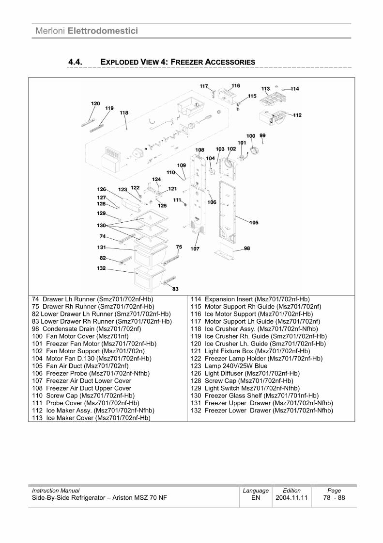
Merloni Elettrodomestici
Instruction Manual Language Edition Page Side-By-Side Refrigerator – Ariston MSZ 70 NF EN 2004.11.11 78 - 88
44..44.. EEXXPPLLOODDEEDD VVIIEEWW 44:: FFRREEEEZZEERR AACCCCEESSSSOORRIIEESS
74 Drawer Lh Runner (Smz701/702nf-Hb) 75 Drawer Rh Runner (Smz701/702nf-Hb) 82 Lower Drawer Lh Runner (Smz701/702nf-Hb) 83 Lower Drawer Rh Runner (Smz701/702nf-Hb) 98 Condensate Drain (Msz701/702nf) 100 Fan Motor Cover (Msz701nf) 101 Freezer Fan Motor (Msz701/702nf-Hb) 102 Fan Motor Support (Msz701/702n) 104 Motor Fan D.130 (Msz701/702nf-Hb) 105 Fan Air Duct (Msz701/702nf) 106 Freezer Probe (Msz701/702nf-Nfhb) 107 Freezer Air Duct Lower Cover 108 Freezer Air Duct Upper Cover 110 Screw Cap (Msz701/702nf-Hb) 111 Probe Cover (Msz701/702nf-Hb) 112 Ice Maker Assy. (Msz701/702nf-Nfhb) 113 Ice Maker Cover (Msz701/702nf-Hb)
114 Expansion Insert (Msz701/702nf-Hb) 115 Motor Support Rh Guide (Msz701/702nf) 116 Ice Motor Support (Msz701/702nf-Hb) 117 Motor Support Lh Guide (Msz701/702nf) 118 Ice Crusher Assy. (Msz701/702nf-Nfhb) 119 Ice Crusher Rh. Guide (Smz701/702nf-Hb) 120 Ice Crusher Lh. Guide (Smz701/702nf-Hb) 121 Light Fixture Box (Msz701/702nf-Hb) 122 Freezer Lamp Holder (Msz701/702nf-Hb) 123 Lamp 240V/25W Blue 126 Light Diffuser (Msz701/702nf-Hb) 128 Screw Cap (Msz701/702nf-Hb) 129 Light Switch Msz701/702nf-Nfhb) 130 Freezer Glass Shelf (Msz701/701nf-Hb) 131 Freezer Upper Drawer (Msz701/702nf-Nfhb) 132 Freezer Lower Drawer (Msz701/702nf-Nfhb)
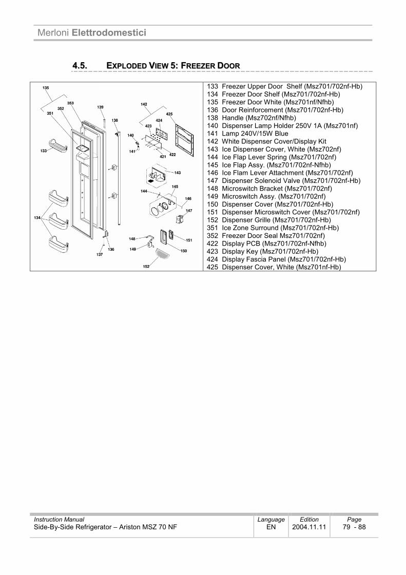
Merloni Elettrodomestici
Instruction Manual Language Edition Page Side-By-Side Refrigerator – Ariston MSZ 70 NF EN 2004.11.11 79 - 88
44..55.. EEXXPPLLOODDEEDD VVIIEEWW 55:: FFRREEEEZZEERR DDOOOORR
133 Freezer Upper Door Shelf (Msz701/702nf-Hb) 134 Freezer Door Shelf (Msz701/702nf-Hb) 135 Freezer Door White (Msz701nf/Nfhb) 136 Door Reinforcement (Msz701/702nf-Hb) 138 Handle (Msz702nf/Nfhb) 140 Dispenser Lamp Holder 250V 1A (Msz701nf) 141 Lamp 240V/15W Blue 142 White Dispenser Cover/Display Kit 143 Ice Dispenser Cover, White (Msz702nf) 144 Ice Flap Lever Spring (Msz701/702nf) 145 Ice Flap Assy. (Msz701/702nf-Nfhb) 146 Ice Flam Lever Attachment (Msz701/702nf) 147 Dispenser Solenoid Valve (Msz701/702nf-Hb) 148 Microswitch Bracket (Msz701/702nf) 149 Microswitch Assy. (Msz701/702nf) 150 Dispenser Cover (Msz701/702nf-Hb) 151 Dispenser Microswitch Cover (Msz701/702nf) 152 Dispenser Grille (Msz701/702nf-Hb) 351 Ice Zone Surround (Msz701/702nf-Hb) 352 Freezer Door Seal Msz701/702nf) 422 Display PCB (Msz701/702nf-Nfhb) 423 Display Key (Msz701/702nf-Hb) 424 Display Fascia Panel (Msz701/702nf-Hb) 425 Dispenser Cover, White (Msz701nf-Hb)
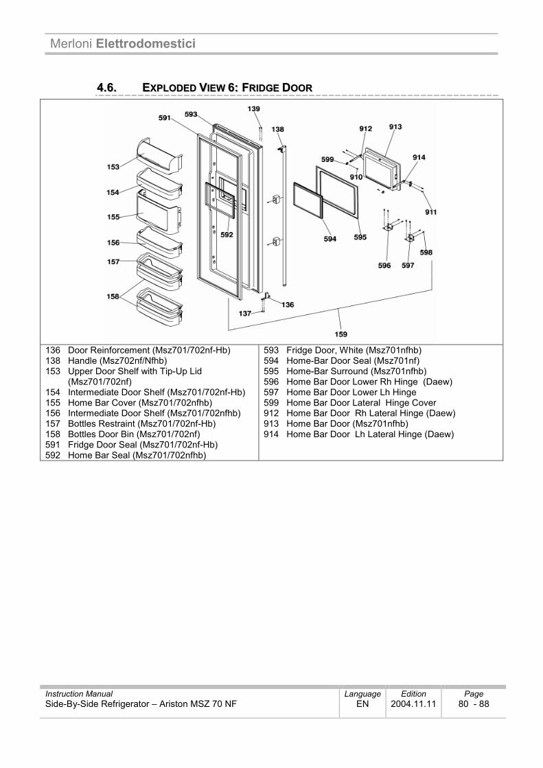
Merloni Elettrodomestici
Instruction Manual Language Edition Page Side-By-Side Refrigerator – Ariston MSZ 70 NF EN 2004.11.11 80 - 88
44..66.. EEXXPPLLOODDEEDD VVIIEEWW 66:: FFRRIIDDGGEE DDOOOORR
136 Door Reinforcement (Msz701/702nf-Hb) 138 Handle (Msz702nf/Nfhb) 153 Upper Door Shelf with Tip-Up Lid (Msz701/702nf) 154 Intermediate Door Shelf (Msz701/702nf-Hb) 155 Home Bar Cover (Msz701/702nfhb) 156 Intermediate Door Shelf (Msz701/702nfhb) 157 Bottles Restraint (Msz701/702nf-Hb) 158 Bottles Door Bin (Msz701/702nf) 591 Fridge Door Seal (Msz701/702nf-Hb) 592 Home Bar Seal (Msz701/702nfhb)
593 Fridge Door, White (Msz701nfhb) 594 Home-Bar Door Seal (Msz701nf) 595 Home-Bar Surround (Msz701nfhb) 596 Home Bar Door Lower Rh Hinge (Daew) 597 Home Bar Door Lower Lh Hinge 599 Home Bar Door Lateral Hinge Cover 912 Home Bar Door Rh Lateral Hinge (Daew) 913 Home Bar Door (Msz701nfhb) 914 Home Bar Door Lh Lateral Hinge (Daew)
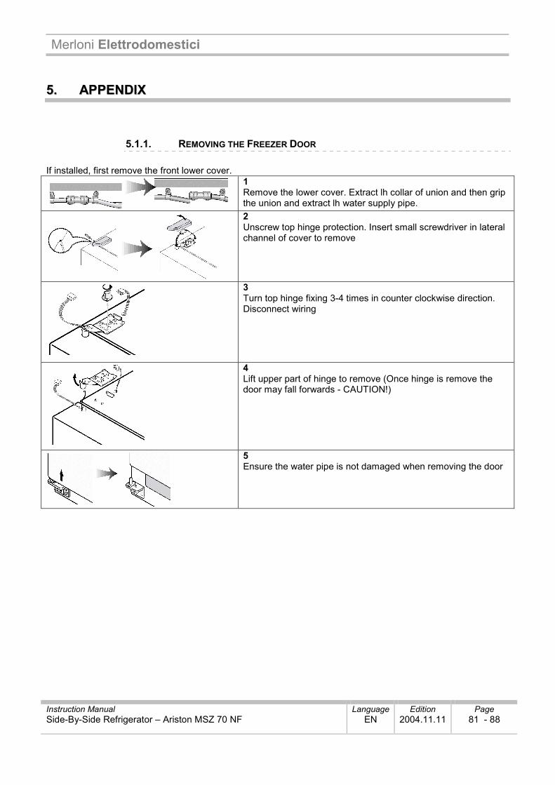
Merloni Elettrodomestici
Instruction Manual Language Edition Page Side-By-Side Refrigerator – Ariston MSZ 70 NF EN 2004.11.11 81 - 88
55.. AAPPPPEENNDDIIXX
5.1.1. REMOVING THE FREEZER DOOR If installed, first remove the front lower cover.
1 Remove the lower cover. Extract lh collar of union and then grip the union and extract lh water supply pipe.
2 Unscrew top hinge protection. Insert small screwdriver in lateral channel of cover to remove
3 Turn top hinge fixing 3-4 times in counter clockwise direction. Disconnect wiring
4 Lift upper part of hinge to remove (Once hinge is remove the door may fall forwards - CAUTION!)
5 Ensure the water pipe is not damaged when removing the door
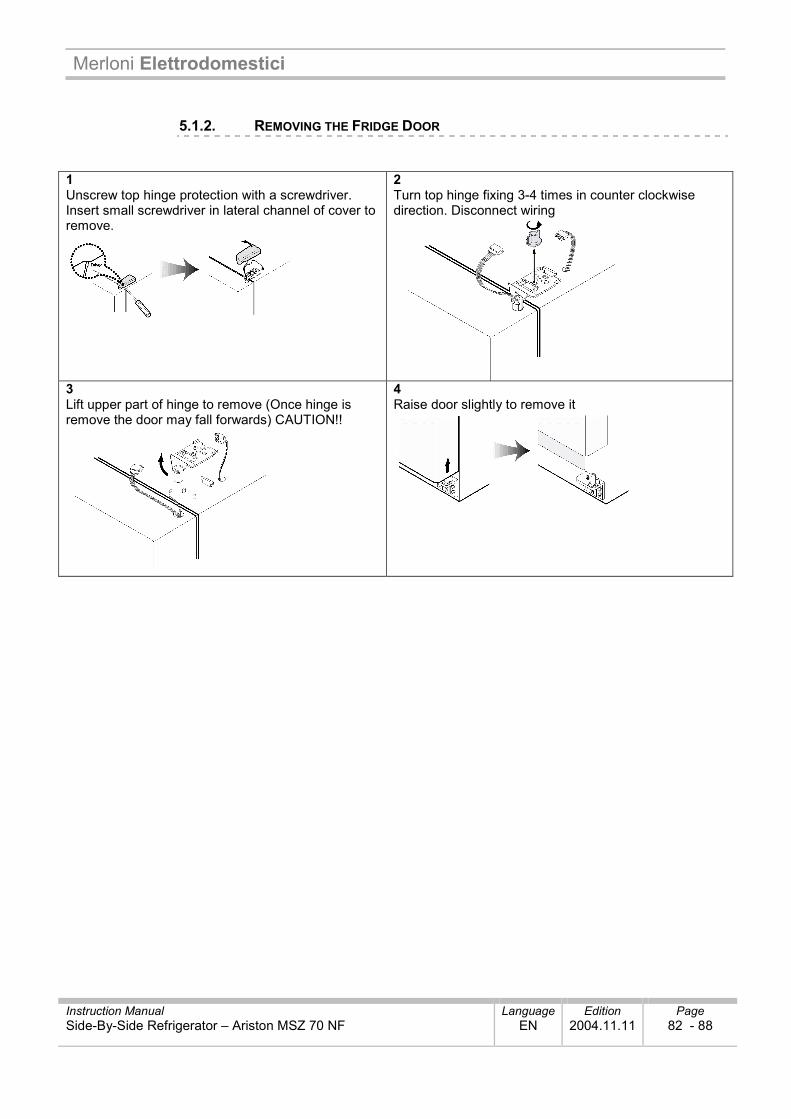
Merloni Elettrodomestici
Instruction Manual Language Edition Page Side-By-Side Refrigerator – Ariston MSZ 70 NF EN 2004.11.11 82 - 88
5.1.2. REMOVING THE FRIDGE DOOR 1 Unscrew top hinge protection with a screwdriver. Insert small screwdriver in lateral channel of cover to remove.
2 Turn top hinge fixing 3-4 times in counter clockwise direction. Disconnect wiring
3 Lift upper part of hinge to remove (Once hinge is remove the door may fall forwards) CAUTION!!
4 Raise door slightly to remove it
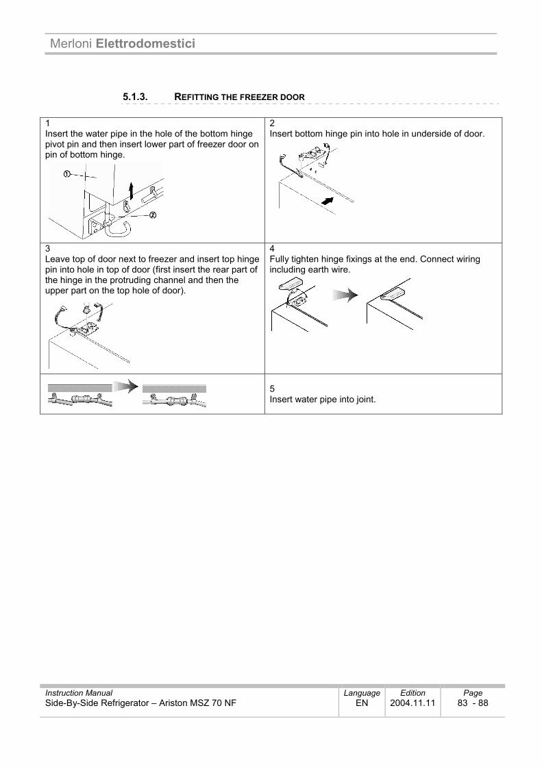
Merloni Elettrodomestici
Instruction Manual Language Edition Page Side-By-Side Refrigerator – Ariston MSZ 70 NF EN 2004.11.11 83 - 88
5.1.3. REFITTING THE FREEZER DOOR 1 Insert the water pipe in the hole of the bottom hinge pivot pin and then insert lower part of freezer door on pin of bottom hinge.
2 Insert bottom hinge pin into hole in underside of door.
3 Leave top of door next to freezer and insert top hinge pin into hole in top of door (first insert the rear part of the hinge in the protruding channel and then the upper part on the top hole of door).
4 Fully tighten hinge fixings at the end. Connect wiring including earth wire.
5 Insert water pipe into joint.
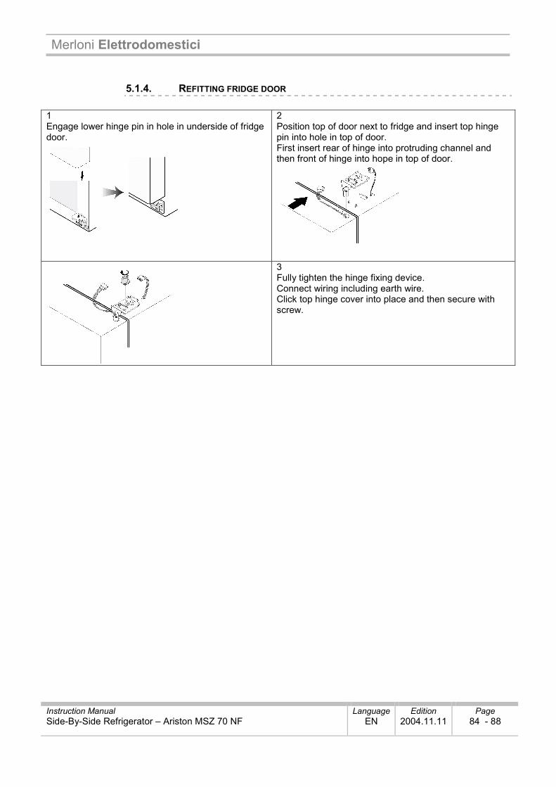
Merloni Elettrodomestici
Instruction Manual Language Edition Page Side-By-Side Refrigerator – Ariston MSZ 70 NF EN 2004.11.11 84 - 88
5.1.4. REFITTING FRIDGE DOOR 1 Engage lower hinge pin in hole in underside of fridge door.
2 Position top of door next to fridge and insert top hinge pin into hole in top of door. First insert rear of hinge into protruding channel and then front of hinge into hope in top of door.
3 Fully tighten the hinge fixing device. Connect wiring including earth wire. Click top hinge cover into place and then secure with screw.
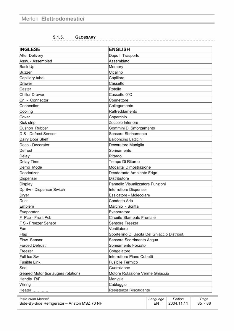
Merloni Elettrodomestici
Instruction Manual Language Edition Page Side-By-Side Refrigerator – Ariston MSZ 70 NF EN 2004.11.11 85 - 88
5.1.5. GLOSSARY INGLESE ENGLISH After Delivery Dopo Il Trasporto Assy. - Assembled Assemblato Back Up Memory Buzzer Cicalino Capillary tube Capillare Drawer Cassetto Caster Rotelle Chiller Drawer Cassetto 0°C Cn - Connector Connettore Connection Collegamento Cooling Raffreddamento Cover Coperchio….. Kick strip Zoccolo Inferiore Cushon Rubber Gommini Di Smorzamento D S - Defrost Sensor Sensore Sbrinamento Dairy Door Shelf Balconcino Latticini Deco - Decorator Decoratore Maniglia Defrost Sbrinamento Delay Ritardo Delay Time Tempo Di Ritardo Demo Mode Modalita' Dimostrazione Deodorizer Deodorante Ambiente Frigo Dispenser Distributore Display Pannello Visualizzatore Funzioni Dp Sw - Dispenser Switch Interruttore Dispenser Dryer Essicatore - Molecolare Duct Condotto Aria Emblem Marchio - Scritta Evaporator Evaporatore F Pcb - Front Pcb Circuito Stampato Frontale F S - Freezer Sensor Sensore Freezer Fan Ventilatore Flap Sportellino Di Uscita Del Ghiaccio Distribut. Flow Sensor Sensore Scorrimento Acqua Forced Defrost Sbrinamento Forzato Freezer Congelatore Full Ice Sw Interruttore Pieno Cubetti Fusible Link Fusibile Termico Seal Guarnizione Geared Motor (ice augers rotation) Motore Rotazione Verme Ghiaccio Handle R/F Maniglia Wiring Cablaggio Heater…………. Resistenza Riscaldante
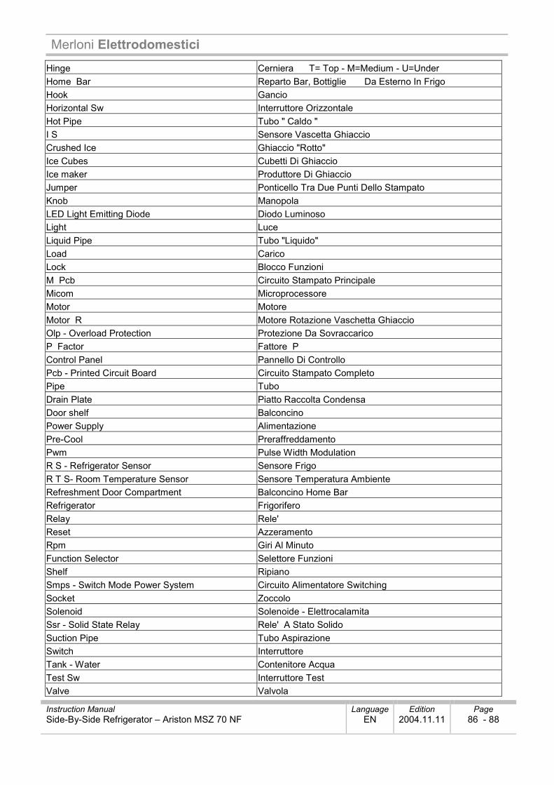
Merloni Elettrodomestici
Instruction Manual Language Edition Page Side-By-Side Refrigerator – Ariston MSZ 70 NF EN 2004.11.11 86 - 88
Hinge Cerniera T= Top - M=Medium - U=Under Home Bar Reparto Bar, Bottiglie Da Esterno In Frigo Hook Gancio Horizontal Sw Interruttore Orizzontale Hot Pipe Tubo " Caldo " I S Sensore Vascetta Ghiaccio Crushed Ice Ghiaccio "Rotto" Ice Cubes Cubetti Di Ghiaccio Ice maker Produttore Di Ghiaccio Jumper Ponticello Tra Due Punti Dello Stampato Knob Manopola LED Light Emitting Diode Diodo Luminoso Light Luce Liquid Pipe Tubo "Liquido" Load Carico Lock Blocco Funzioni M Pcb Circuito Stampato Principale Micom Microprocessore Motor Motore Motor R Motore Rotazione Vaschetta Ghiaccio Olp - Overload Protection Protezione Da Sovraccarico P Factor Fattore P Control Panel Pannello Di Controllo Pcb - Printed Circuit Board Circuito Stampato Completo Pipe Tubo Drain Plate Piatto Raccolta Condensa Door shelf Balconcino Power Supply Alimentazione Pre-Cool Preraffreddamento Pwm Pulse Width Modulation R S - Refrigerator Sensor Sensore Frigo R T S- Room Temperature Sensor Sensore Temperatura Ambiente Refreshment Door Compartment Balconcino Home Bar Refrigerator Frigorifero Relay Rele' Reset Azzeramento Rpm Giri Al Minuto Function Selector Selettore Funzioni Shelf Ripiano Smps - Switch Mode Power System Circuito Alimentatore Switching Socket Zoccolo Solenoid Solenoide - Elettrocalamita Ssr - Solid State Relay Rele' A Stato Solido Suction Pipe Tubo Aspirazione Switch Interruttore Tank - Water Contenitore Acqua Test Sw Interruttore Test Valve Valvola
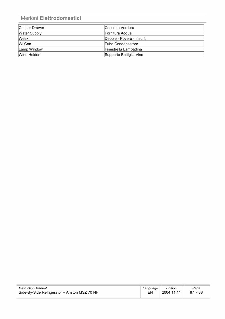
Merloni Elettrodomestici
Instruction Manual Language Edition Page Side-By-Side Refrigerator – Ariston MSZ 70 NF EN 2004.11.11 87 - 88
Crisper Drawer Cassetto Verdura Water Supply Fornitura Acqua Weak Debole - Povero - Insuff. Wi Con Tubo Condensatore Lamp Window Finestrella Lampadina Wine Holder Supporto Bottiglia Vino
Merloni Elettrodomestici
Instruction Manual Language Edition Page Side-By-Side Refrigerator – Ariston MSZ 70 NF EN 2004.11.11 88 - 88
Merloni Elettrodomestici S.p.A. viale Aristide Merloni, 47 60044 Fabriano – Italy tel. +39 0732 66 11 - telex 560196 - fax +39 0732 66 2954 - www.Merloni.com