Shark 01 18 - proteco.net · • Per un uso proprio del prodotto e per escludere ogni possibilità...
11
01_2018 Shark New PRODOTTI PRODUITS PRODUCTS ERZEUGNIS PRODUCTOS Manuale d’Installazione e d’Uso Notice d'Installation et Utilisation Installation and use manual Handbuch der Installation und des Gebrauchs Manual de Uso e Instalación AUTOMAZIONI PER CANCELLI A BATTENTE AUTOMATISMES POUR PORTAILS A BATTANTS AUTOMATION FOR SWING GATES AUTOMATISIERUNG FÜR FLÜGELTORE AUTOMATISMOS PARA BATIENTES Proteco S.r.l. Via Neive, 77 - 12050 Castagnito (CN) ITALY Tel. +39 0173 210111 - Fax +39 0173 210199 www.proteco.net - [email protected]
Transcript of Shark 01 18 - proteco.net · • Per un uso proprio del prodotto e per escludere ogni possibilità...

01_2018
Shark New
PRODOTTIPRODUITSPRODUCTSERZEUGNISPRODUCTOS
Manuale d’Installazione e d’UsoNotice d'Installation et Utilisation
Installation and use manualHandbuch der Installation und des Gebrauchs
Manual de Uso e Instalación
AUTOMAZIONI PER CANCELLI A BATTENTE AUTOMATISMES POUR PORTAILS A BATTANTS
AUTOMATION FOR SWING GATES AUTOMATISIERUNG FÜR FLÜGELTORE
AUTOMATISMOS PARA BATIENTES
Proteco S.r.l. Via Neive, 77 - 12050 Castagnito (CN) ITALY Tel. +39 0173 210111 - Fax +39 0173 210199 www.proteco.net - [email protected]
65
160
315
415
B
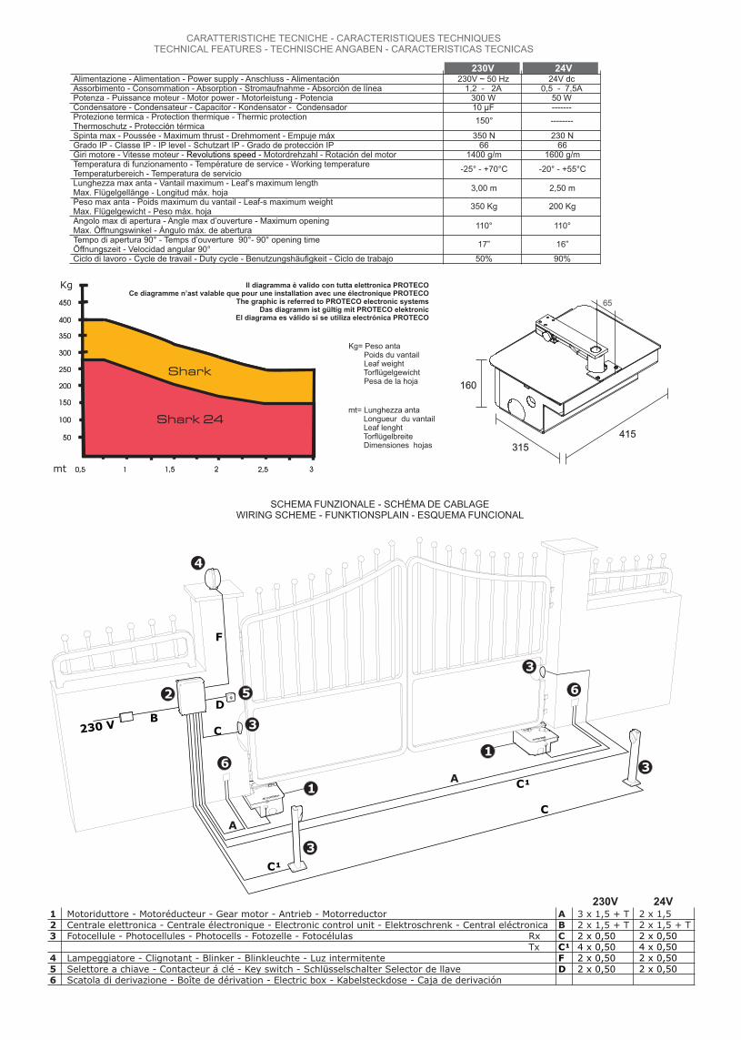
SCHEMA FUNZIONALE - SCHÉMA DE CABLAGEWIRING SCHEME - FUNKTIONSPLAIN - ESQUEMA FUNCIONAL
24V230V24V dc
0,5 - 7,5A50 W-------
230V ~ 50 Hz1,2 - 2A
300 W10 µF
230 N66
1600 g/m
2,50 m3,00 m
200 Kg350 Kg
110°110°
16”17”
90%50%
350 N66
1400 g/m
--------150°
-20° - +55°C-25° - +70°C
mt= Lunghezza anta Longueur du vantail Leaf lenght Torflügelbreite Dimensiones hojas
Kg= Peso anta Poids du vantail Leaf weight Torflügelgewicht Pesa de la hoja
Il diagramma è valido con tutta elettronica PROTECOCe diagramme n’ast valable que pour une installation avec une électronique PROTECO
The graphic is referred to PROTECO electronic systemsDas diagramm ist gültig mit PROTECO elektronic
El diagrama es válido si se utiliza electrónica PROTECO
Alimentazione - Alimentation - Power supply - Anschluss - Alimentaci n óAssorbimento - Consommation - Absorption - Stromaufnahme - Absorción de líneaPotenza - Puissance moteur - Motor power - Motorleistung - Potencia Condensatore - Condensateur - Capacitor - Kondensator - CondensadorProtezione termica - Protection thermique - Thermic protectionThermoschutz - Protecci n térmicaóSpinta max - Poussée - Maximum thrust - Drehmoment - Empuje máxGrado IP - Classe IP - IP level - Schutzart IP - Grado de protección IPGiri motore - Vitesse moteur - Motordrehzahl - Rotación del motorRevolutions speed -Temperatura di funzionamento - Température de service - Working temperature Temperaturbereich - Temperatura de servicioLunghezza max anta - Vantail maximum - Leaf’s maximum length Max. Flügelgellänge - Longitud máx. hojaPeso max anta - Poids maximum du vantail - Leaf-s maximum weight Max. Flügelgewicht - Peso máx. hojaAngolo max di apertura - Angle max d’ouverture - Maximum opening Max. Öffnungswinkel - Ángulo máx. de abertura Tempo di apertura 90° - Temps d’ouverture 90°- 90° opening time Öffnungszeit - Velocidad angular 90°Ciclo di lavoro - Cycle de travail - Duty cycle - Benutzungshäufigkeit - Ciclo de trabajo
CARATTERISTICHE TECNICHE - CARACTERISTIQUES TECHNIQUES TECHNICAL FEATURES - TECHNISCHE ANGABEN - CARACTERISTICAS TECNICAS
50
100
150
200
250
300
350
400
450
0,5 1 1,5 2 2,5 3
50
100
150
200
250
300
350
400
450
0,5 1 1,5 2 2,5 3
Shark 24
Shark
Kg
mt
1 Motoriduttore - Motoréducteur - Gear motor - Antrieb - Motorreductor2 Centrale elettronica - Centrale électronique - Electronic control unit - Elektroschrenk - Central eléctronica3 Fotocellule - Photocellules - Photocells - Fotozelle - Fotocélulas Rx Tx4 Lampeggiatore - Clignotant - Blinker - Blinkleuchte - Luz intermitente5 Selettore a chiave - Contacteur á clé - Key switch - Schl sselschalter Selector de llaveü6 Scatola di derivazione - Boîte de dérivation - Electric box - Kabelsteckdose - Caja de derivación
ABCC¹FD
3 x 1,5 + T2 x 1,5 + T2 x 0,504 x 0,502 x 0,502 x 0,50
2 x 1,5 2 x 1,5 + T2 x 0,504 x 0,502 x 0,502 x 0,50
6
65
4
A
A
3
3
3
3
2
1
1
C¹
C¹
C
C
F
DB
230 V
230V 24V

Dado M 12x4
F2
F1
COMPOSIZIONE - COMPOSITION - COMPOSITION - KOMPOSITION - COMPOSICION
01
1515
14
02
04
07
10
06
0301 n°1 Motoriduttore 02 n°1 Cassetta di fondazione 03 n°1 Coperchio 04 n°1 Supporto anta05 n°1 Leva di trasmissione06 n°1 Condensatore 10 Fµ07 n°1 Leva di sblocco 08 n°4 Dadi autobloc. M12 per fissaggio motore 09 n°2 Rondelle 8x3210 n°1 Sfera Ø2511 n°4 Viti a brugola TPSEI 6x10 inox12 n°1 Piastra per chiusura foro coperchio13 n°4 Rondelle 12x24 zinc.14 n°2 Viti 3,5x9,5 per piastra chiusura foro
coperchio15 n°2 Nottolino protezione dispositivo di sblocco16 n°1 Fermo meccanico chiusura17 n°1 Fermo meccanico apertura18 n°1 Manuale d’installazione ed uso
01 n°1 - - - Motoréducteur Motor Motor Motor02 n°1 - - - Caisson de fondation Foundation box Unterflurgehäus Caja de fundación03 n°1 - - - Couvercle Cover Gehäusedeckel Tapa04 n°1 - - - Support vantail Gate leaf support Türflügel Stütze Soporte hoja 05 n°1 - - - Levier de transmission Transmission lever Kraftübertragungshebel Palanca de transmissión06 n°1 - - - Condensateur 10 µF Condenser 10 uF Kondensator 10 uF Condensador 10 uF07 n°1 - - - Système de déverrouillage Release lever Freigabe Hebel Palanca de desbloqueo08 n°4 - - Ecrous autobloquant pour fixation moteur M12 nuts to fix the motor Schraubenmutter M 12 für Motorfixierung
Tuercas M12 para sujetar el motor09 n°2 - - - Rondelles 8x32 8x32 washers Unerlegscheiben 8x 32 Arandelas 8x3210 n°1 - - - Bille Ø25 ø25 ball Kugellager ø25 Bola ø2511 n°4 - - Vis TPSEI 6x10 inox TPSEI 6x10 galvanised screws Sechskantschrauben PTSEI 6x10 verzinkt
Tornillos galvanizados TPSEI 6x10 12 n°1 - -Patte fermeture couvercle Plate to close the cover hole Scheibe für Motordeckellochung Schließung
Chapa para cerrar el agujero de la tapa13 n°4 - - - Rondelles 12x24 12x24 washers Unterlegscheiben 12x24 Arandelas 12x2414 n°2 - Vis 3.5x9.5 pour patte fermeture couvercle 3,5x9,5 screws to close the cover hole
- Sperrklinke für Motorschutzfreigabe Tornillos 3,5x9,5 para cerrar el agujero de la tapa15 n°2 - - - Cliquet protection déverrouillage Release key Sperrklinke für Motorschutzfreigabe Llave de desbloqueo16 n°1 - - Fin de course fermeture Mechanical limit switch for closing Final de carrera mecánico en cierre17 n°1 - - Fin de course ouverture Mechanical limit switch for opening Final de carrera mecánico en abertura18 n°1 - - - Notice d’installation Installations- und Gebrauchsanweisung Installation manual Manual de instrucciones
13
05
08
151616 17
11
12
09
Fig. B
110°
Fig. A
90°
Fig. C
2 1Posizioneverticale
Posizioneorizzontale
Fig. D
Scavo di fondazioneDiggingexcavaci n de fundaci nó ó 58
65
Fig. E Fig. G

P2
P1C
Fig. G
Sfera
Fig. H
Fig. M
Fig. O Fig. P
L3
L1
L2
L1
Fig. I
1 GIRARE IN SENSO ORARIO 2 SFILARE
Fig. L
INTERNO - INTÉRIEURINSIDE INTERIOR INNENSEITE - -
INTERNO - - - INTÉRIEUR - INSIDE INTERIOR INNENSEITE
INTERNO - - - INTÉRIEUR - INSIDE INTERIOR INNENSEITE
Motoriduttore DESTRO
Motoriduttore SINISTRO
FERMO APERTURA
FERMO APERTURA
FERMO CHIUSURA
FERMO CHIUSURA
ESTERNO - EXTÉRIEUR - OUTSIDE - EXTERIOR AUßENSEITE
DxSx
Fig. N
F2 Ø 35 mm
F1 Ø 70 mm
Drenaggioacqua
Ingresso cavomotore
INTERNO - INTÉRIEURINSIDE INTERIOR INNENSEITE - -
ESTERNO - EXTÉRIEUR - OUTSIDE - EXTERIOR AUßENSEITE
DxSx
POSIZIONAMENTO MOTORI PER APERTURA VERSO L’INTERNO
POSIZIONAMENTO MOTORI PER APERTURA VERSO L’ESTERNO

CRITERI DI SICUREZZA1 Prima d’iniziare qualsiasi operazione d’installazione è assolutamente
necessario leggere tutto il presente manuale.2 Verificare che le prestazioni dell motoriduttore acquistato corrispondano
alle vostre esigenze d’ installazione.3 Inoltre verificare che:
- Le cerniere del cancello siano in buono stato e perfettamente ingrassate.- Il cancello sia dotato di fermi meccanici in apertura ed in chiusura.
CONSIGLI PER L’INSTALLAZIONECollegamenti:• Vedere “Schema funzionale” e fare riferimento agli schemi della
centrale di comando.• Tutti i collegamenti devono essere effettuati in assenza di
alimentazione.• Prevedere un dispositivo di sezionamento onnipolare nelle vicinanze
dell’apparecchio (i contatti devono essere di almeno 3 mm) Proteggere sempre l’alimentazione per mezzo di un interruttore
automatico da 6A, oppure per mezzo di un interruttore monofase da 16A completo di fusibili.
• Le linee di alimentazione ai motori, alla centrale e le linee di collegamento agli accessori devono essere separate onde evitare disturbi che potrebbero generare mal funzionamenti dell’impianto.
• Qualsiasi apparecchiatura (di comando o sicurezza) eventualmente asservita alla centrale deve essere libera da tensione (contatti puliti).
Parti di ricambio:• Utilizzare solamente parti di ricambio originali.Modalità d’ installazione:• Per un uso proprio del prodotto e per escludere ogni possibilità di
danneggiamenti a persone, animali o cose, fare riferimento al foglio "Generalità" allegato che fa parte integrante del presente manuale.
• L'impiego di questa apparecchiatura deve rispettare le norme di sicurezza vigenti nel paese d’installazione oltre alle norme di buona installazione.
Garanzia:• La garanzia fornita dal costruttore decade in caso di manomissione,
incuria, uso improprio, fulmini, sovratensioni o utilizzo da parte di personale non professionalmente qualificato.
• Fa inoltre decadere qualsiasi diritto alla garanzia: non rispettare le istruzioni riportate sui manuali allegati ai prodotti.
L'applicazione anche di un solo particolare in modo non rispondente alla legislazione vigente o l'utilizzo di parti di ricambio non congeniali e/o non espressamente approvata dalla ditta costruttrice.
• Il costruttore non può considerarsi responsabile per eventuali danni causati da usi impropri ed irragionevoli.
SEQUENZA DI INSTALLAZIONE1 Prima d’iniziare la messa in opera, effettuare sull’installazione l’analisi
dei rischi facendo riferimento al foglio “Generalità“ che fa parte integrante del presente manuale, riempire la tabella tecnica ed eliminare i rischi rilevati.
Nel caso in cui vi siano rischi residui, prevedere l’installazione con sistemi di sicurezza e completamento.
2 Verificare le norme di sicurezza citate nei “Criteri di sicurezza”.3 Identificare tutti i componenti.4 Identificare l’esatta posizione del GRUPPO MOTORE.5 Praticare sul terreno nella posizione stabilita uno scavo di Fondazione.6 Posizionare la cassetta di Fondazione all’interno dello scavo di
Fondazione.7 Prevedere uno scarico per l’acqua.8 Stendere i cavi come da “Schema funzionale ”9 Posizionare e fissare il motoriduttore all’interno della cassetta di
Fondazione.10 Montare il gruppo di leve per il movimento del cancello.11 Chiudere la cassetta di Fondazione.12 Posizionare e fissare l’anta del cancello.13 Collegare la centrale e tutti gli accessori.14 Programmare il ricevitore radio.15 Eseguire la programmazione dei “Tempi di funzionamento”. In caso di mal funzionamento, fare riferimento alla tabella “Anomalie e
Consigli”.NEL CASO IN CUI NON RIUSCIATE A TROVARE ALCUNA SOLUZIONE TELEFONARE AL PIÙ VICINO CENTRO DI ASSISTENZA.
ATTUATORE BLOCCATO I motoriduttori interrati con leva di trasmissione a movimento sono forniti in versione bloccata.
DETERMINAZIONE POSIZIONEAdattare in base al tipo di struttura e di apertura che si vuole, l’esatta posizione della cassetta di Fondazione seguendo le indicazioni:• Cancello fissato al centro del pilastrino (FIG. A) In questo caso l’angolo massimo di apertura del cancello è di 90°.• Cancello fissato sullo spigolo interno del pilastrino (FIG. B) In questo caso il cancello può aprire con un angolo maggiore di 90°.
(max 110°)
POSIZIONAMENTO CASSETTA DI FONDAZIONE E MOTORIDUTTORE
- Praticare nel terreno uno scavo nella posizione stabilita di dimensioni tali da poter contenere la cassetta di Fondazione. (Fig. D)
- Posizionare la Cassetta di Fondazione all’interno dello Scavo assicurandosi che il perno sia allineato al cardine dell’anta del cancello, mantenendo una distanza di 65 mm dal centro cardine al pilastro. (Fig. E)
- Eseguire in prossimità del foro F1 (Fig. N) della cassetta di Fondazione uno scarico per l’acqua, che ne eviti, il ristagno.
- Prevedere l’ingresso dei cavi elettrici attraverso il foro F2 della cassetta. (Fig. N)
- Interrare la cassetta di Fondazione utilizzando del calcestruzzo, curandone la messa in bolla e la corretta posizione.
- Posizionare la sfera nell’apposita sede dopo averla precedentemente ingrassata, procedere posizionando il supporto anta “L1” nel perno della cassetta. (Fig. G)
- Posizionare l’anta del cancello sul supporto anta “L1” in modo che siano perfettamente in asse il cardine dell’anta con il centro di rotazione del supporto “L1”. (Fig. E)
- Posizionare il motoriduttore sul fondo della cassetta (assicurarsi che sia perfettamente libero da eventuali residui di calcestruzzo) rispettare l’orientamento del motore dx / sx seguendo la (fig. M) e fissarlo ai perni filettati con rondelle e dadi M12. (Fig. F)
N.B.: Nel caso il cancello apra verso l’esterno è possibile
posizionare il motore all’interno della cassetta di Fondazione ruotandolo di 180°. (fig. M)
- Montare la leva ”L2” leva di Trasmissione unendo il supporto anta “L1” al motore tenendo presente che la parte più grande deve essere posizionata sul supporto anta “L1” (Fig. H) e fissarla con rondelle e viti.
- Chiudere la cassetta di Fondazione, con il coperchio fissandolo con le viti in dotazione.
FERMI MECCANICI (fig. O)Nonostante il motoriduttore sia dotato di fermi meccanici in apertura e chiusura, è consigliabile la messa in opera di fermi in battuta sulle ante.
MANOVRA D’EMERGENZA (sblocco dell’anta)- Inserire la chiave nel nottolino di protezione sblocco posizionato nel
supporto anta. (Fig. I) - Girare in senso orario e estrarre il gruppo.- Inserire la leva di sblocco nell’apposito foro e ruotare sempre verso il
centro del cancello. (Fig. L)- A questo punto è possibile aprire e chiudere manualmente il cancello. L’automazione si ripristina automaticamente alla prima manovra.- Riposizionare i nottolini di protezione sblocco.
DISPOSITIVO PER APERTURA 180° (A 008)Il dispositivo viene utilizzato in casi particolari, per rendere possibili aperture superiori da 110° a 180°.- Sostituire la biella del motore con il pignone motore “P1”; fissare con la
vite TCE 10x70 e dado M10 ( girare solo la vite, il dado rimane fermo nella sua sede). Fig. P
- Sostituire il supporto anta inferiore in dotazione con il pignone supporto anta “P2”.
- Unire le due parti mediante la catena di trasmissione “C” e inserire maglia di giunzione.
POSIZIONE DELL’ELETTROSERRATURA (Fig. C)L’elettroserratura deve essere installata sull’anta che si apre per prima e deve essere collegata ai relativi morsetti della centrale.
Posizione 1: Posizionamento in orizzontale con aggancio all’ anta che si chiude per prima (in questo caso è necessario utilizzare il blocco a paletto sull’anta che si chiude per prima)Posizione 2: Posizionamento in verticale con aggancio a terra.
Ricordarsi di o rendere inattiva l’eventuale serratura meccanica preesistente.
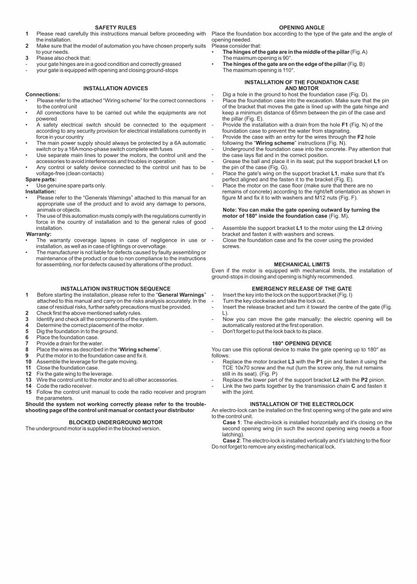
SAFETY RULES1 Please read carefully this instructions manual before proceeding with
the installation.2 Make sure that the model of automation you have chosen properly suits
to your needs.3 Please also check that:- your gate hinges are in a good condition and correctly greased- your gate is equipped with opening and closing ground-stops
INSTALLATION ADVICESConnections:• Please refer to the attached “Wiring scheme” for the correct connections
to the control unit• All connections have to be carried out while the equipments are not
powered• A safety electrical switch should be connected to the equipment
according to any security provision for electrical installations currently in force in your country
• The main power supply should always be protected by a 6A automatic switch or by a 16A mono-phase switch complete with fuses
• Use separate main lines to power the motors, the control unit and the accessories to avoid interferences and troubles in operation
• Any control or safety device connected to the control unit has to be voltage-free (clean contacts)
Spare parts: • Use genuine spare parts only.Installation:• Please refer to the “Generals Warnings” attached to this manual for an
appropriate use of the product and to avoid any damage to persons, animals or objects.
• The use of this automation musts comply with the regulations currently in force in the country of installation and to the general rules of good installation.
Warranty:• The warranty coverage lapses in case of negligence in use or
installation, as well as in case of lightings or overvoltage.• The manufacturer is not liable for defects caused by faulty assembling or
maintenance of the product or due to non compliance to the instructions for assembling, nor for defects caused by alterations of the product.
INSTALLATION INSTRUCTION SEQUENCE1 Before starting the installation, please refer to the “General Warnings”
attached to this manual and carry on the risks analysis accurately. In the case of residual risks, further safety precautions must be provided.
2 Check first the above mentioned safety rules.3 Identify and check all the components of the system.4 Determine the correct placement of the motor.5 Dig the foundation in to the ground.6 Place the foundation case.7 Provide a drain for the water.8 Place the wires as described in the “Wiring scheme”.9 Put the motor in to the foundation case and fix it.10 Assemble the leverage for the gate moving.11 Close the foundation case.12 Fix the gate wing to the leverage.13 Wire the control unit to the motor and to all other accessories.14 Code the radio receiver.15 Follow the control unit manual to code the radio receiver and program
the parameters.Should the system not working correctly please refer to the trouble-shooting page of the control unit manual or contact your distributor
BLOCKED UNDERGROUND MOTORThe underground motor is supplied in the blocked version.
OPENING ANGLEPlace the foundation box according to the type of the gate and the angle of opening needed.Please consider that:• The hinges of the gate are in the middle of the pillar (Fig. A) The maximum opening is 90°.• The hinges of the gate are on the edge of the pillar (Fig. B) The maximum opening is 110°.
INSTALLATION OF THE FOUNDATION CASE AND MOTOR
- Dig a hole in the ground to host the foundation case (Fig. D).- Place the foundation case into the excavation. Make sure that the pin
of the bracket that moves the gate is lined up with the gate hinge and keep a minimum distance of 65mm between the pin of the case and the pillar (Fig. E).
- Provide the installation with a drain from the hole F1 (Fig. N) of the foundation case to prevent the water from stagnating.
- Provide the case with an entry for the wires through the F2 hole following the “Wiring scheme” instructions (Fig. N).
- Underground the foundation case into the concrete. Pay attention that the case lays flat and in the correct position.
- Grease the ball and place it in its seat; put the support bracket L1 on the pin of the case (Fig. G).
- Place the gate's wing on the support bracket L1, make sure that it's perfect aligned and the fasten it to the bracket (Fig. E).
- Place the motor on the case floor (make sure that there are no remains of concrete) according to the right/left orientation as shown in figure M and fix it to with washers and M12 nuts (Fig. F).
Note: You can make the gate opening outward by turning the motor of 180° inside the foundation case (Fig. M).
- Assemble the support bracket L1 to the motor using the L2 driving bracket and fasten it with washers and screws.
- Close the foundation case and fix the cover using the provided screws.
MECHANICAL LIMITSEven if the motor is equipped with mechanical limits, the installation of ground-stops in closing and opening is highly recommended.
EMERGENCY RELEASE OF THE GATE- Insert the key into the lock on the support bracket (Fig. I)- Turn the key clockwise and take the lock out.- Insert the release bracket and turn it toward the centre of the gate (Fig.
L).- Now you can move the gate manually: the electric opening will be
automatically restored at the first operation.- Don't forget to put the lock back to its place.
180° OPENING DEVICEYou can use this optional device to make the gate opening up to 180° as follows:- Replace the motor bracket L3 with the P1 pin and fasten it using the
TCE 10x70 screw and the nut (turn the screw only, the nut remains still in its seat). (Fig. P)
- Replace the lower part of the support bracket L2 with the P2 pinion.- Link the two parts together by the transmission chain C and fasten it
with the joint.
INSTALLATION OF THE ELECTROLOCKAn electro-lock can be installed on the first opening wing of the gate and wire to the control unit. Case 1: The electro-lock is installed horizontally and it's closing on the
second opening wing (in such the second opening wing needs a floor latching).
Case 2: The electro-lock is installed vertically and it's latching to the floorDo not forget to remove any existing mechanical lock.

CONTROLES PRELIMINAIRES DE SECURITE1 Avant de procéder à l'installation il faut absolument lire avec attention cette
notice.2 Assurez-vous que le modèle de motorisation que vous avez choisi
corresponde à vos exigences.3 Vérifiez aussi que:- la structure de votre portail soit en bonne condition et bien graissée.- votre portail soit équipé avec des butées au sol en ouverture comme en
fermeture.
CONSEILS POUR L'INSTALLATIONBranchements• Voir le “Schéma de câblage” ci-joint pour les branchements de la carte
électronique.• Tous les branchements doivent être effectués en absence de tension• Pourvoir l'installation d'un switch (les contacts doivent être au moins
de 3mm). Protégez la ligne d'alimentation électrique par un coupe-circuit automatique de 6A ou par un interrupteur monophasé de 16A avec fusibles.
• Les lignes d'alimentation des moteurs, de la carte électronique et les câblages des accessoires doivent être séparées pour éviter interférences et/ou défaillances du système.
• Tous les appareils (de commande et de sécurité) éventuellement branchés à la carte électronique ne doivent pas être sous tension (contacts propres).
Pièces de rechange• .Utiliser seulement pièces de rechange originalesInstallation• Pour un usage correct du produit et pour ne pas nuire à personnes,
animaux ou objets, respectez soigneusement les avertissements indiqués dans les “Généralités” jointes à cette notice.
• L'installation et l'utilisation de cette motorisation doivent être effectuées dans le plein respect des lois, des normes et des règlements en vigueur aussi que des normes générales de bonne installation.
GarantieToute garantie déchoit en cas d'usage abusif du produit, incurie, foudres ou surtensions.Le fabricant n'est pas responsable des pannes et défaillances causées par une mauvaise installation ou entretien ou imputables au non-respect de la notice d'utilisation et entretien ou à altérations du produit effectués sans concertation et avis écrits du fabricant.
SEQUENCE D'INSTALLATION1 Avant de procéder à l'installation, effectuer l'analyse des risques comme
indiqué dans les “Généralités” jointes a ce manuel.2 Vérifiez les normes de sécurité citées dans le chapitre ci-dessus
«Contrôles préliminaires de sécurité ».3 Identifiez et contrôlez tous les composants du système.4 Choisissez la position correcte du moteur.5 Creusez un trou de fondation.6 Positionnez le caisson de fondation dans le trou.7 Pourvoyez l'installation d'un écoulement de drainage.8 Faites arriver un conduit pour le passage des câbles électriques.9 Fixez le moteur dans le caisson de fondation.10 Assemblez les leviers pour le mouvement du portail.11 Fermez le caisson de fondation.12 Fixez le vantail du portail.13 Branchez la carte électronique et les accessoires.14 Programmez le récepteur radio.15 Suivez la notice de la carte électronique pour programmer les temps
de travail et les autres paramètres de la motorisation.EN CAS LE SYSTÈME NE FONCTIONNE PAS CORRECTEMENT REFEREZ-VOUS AU CHAPITRE “ANOMALIES ET CONSEIL” DANS LA NOTICE DE LA CARTE OU APPELEZ VOTRE DISTRIBUTEUR.
MOTEUR AUTOBLOQUANTLes moteurs pour montage enterré sont fournis en version autobloquant.
ANGLE DE OUVERTUREPositionnez le caisson de fondation compte tenu du type de portail et de l'angle d'ouverture souhaité. Considérez que:• Vantail au milieu du pilier (Fig. A) Angle maximum d'ouverture 90° • Vantail au bord du pilier (Fig. B) Angle maximum d'ouverture 110°
INSTALLATION DU CAISSON ET DU MOTEUR- Creusez le trou dans la position choisie pour loger le caisson de
fondation (Fig. D).- Posez le caisson dans la fouille. Assurez-vous que le tourillon du
caisson soit en ligne avec le gond du portail et gardez une distance de minimum 65mm entre le tourillon et le pilier (Fig. E).
- Pourvoyez l'installation d'un écoulement près du trou du caisson F1 (Fig. N) pour éviter la stagnation des eaux.
- Faites arriver un conduit pour le passage de câbles au trou F2 du caisson (Fig. N).
- Coulez le ciment et maintenez le caisson enfoncé en veillant qui il soit dans la position correcte et au niveau.
- Graissez la bille et introduisez-la dans son logement. Mettez la patte de support L1 du vantail sur le tourillon du caisson (Fig. G).
- Placez le vantail sur la patte de support L1, assurez-vous qu'ils soient en ligne parfaite entre eux et fixez (Fig. E).
- Logez le moteur dans le caisson (assurez-vous qu'ils ne restent pas des résidus de ciment) en respectant l'orientation droite/gauche du moteur comme indique (Fig. M) et fixez-le aux goujons à l'aide des entretoises et des écrous M12 (Fig. F).
N.B.: Dans le cas que le portail s'ouvre vers l'extérieur positionnez le moteur dans le caisson tourné de 180°. (Fig. M)
- Assemblez la patte de support L1 au moteur avec la patte de transmission L2 (vérifiez que l'extrémité plus grande soit vers la patte L1) et serrez avec vis et entretoises.
- Fermez le couvercle du caisson et serrez avec les vis en dotation.
FINS DE COURSE MECANIQUES (Fig. O)Même si le moteur est équipé avec fins de course mécaniques en ouverture et fermeture, on conseille l'installation de butées au sol pour les vantaux.
MANOEVRE DE SECOURS (Déverrouillage du vantail)- Introduisez la clé dans la serrure sur la patte de support (Fig. I).- Tournez la clé dans le sens des aguilles d'une montre et sortez le
groupe serrure.- Insérez le levier et tournez vers le milieu du portail (Fig. L).- Maintenant vous pouvez déplacer le vantail à la main: la motorisation
se rétablisse automatiquement lors de la prochaine manœuvre.- Remettez le groupe serrure à sa place.
SYSTEME POUR OUVERTURE A 180°Vous pouvez utiliser ce dispositif en option pour obtenir une ouverture supérieure jusqu'à 180°:- Remplacez la bielle moteur L3 avec le pivot P1 et serrez à l'aide des
vis TCE 10x70 et des écrous (tournez la vis seulement, l'écrou reste immobile dans son logement). (Fig. P)
- Remplacez la partie inferieure de la patte de support L2 avec le pignon P2.
- Reliez les deux parties par la chaîne de transmission C et fermez avec le maillon de jonction.
INSTALLATION DE L'ELECTROSERRUREUne électro serrure, branchée à la carte électronique peut être installe sur le vantail que s'ouvre le premier.Option 1 L'électro serrure est montée horizontalement et s'accroche sur le vantail que s'ouvre pour deuxième (dans ce cas il faut installer aussi un verrou au sol sur le vantail qui s'ouvre le deuxième).Option 2 L'électro serrure est montée verticalement avec gâche au solN'oubliez pas d'enlever toute serrure préexistante.

CRITERIOS DE SEGURIDAD1 Antes de empezar la instalación leer atentamente todo el presete manual2 Asegurarse que el rendimiento de este motorreductor corresponda a
vuestras exigencias de instalación.3 Además averiguar que: - las bisagras sean en buenas condiciones y perfectamente lubricadas - la cancela tenga topes mecánicos en abertura y cierre.
ADVERTENCIAS PARA LA INSTALACIÓNConexiones• Ver “Esquema funcional” y hacer referencia a los esquemas del
cuadro de maniobra.• Todas las conexiones tienen que ser efectuadas en absencia de
suministro de corriente.• Planear un aparato de seccionamiento omnipolar cerca del dispositivo
(los contactos tienen que ser de 3 mm como mínimo). Proteger siempre lel suministro de corriente por medio de un interruptor
automático de 6A, o por medio de un interruptor monofásico de 16A completo de fusibles.
• Las lineas de suministros de corriente a los motores, al cuadro y las lineas de conexiones a los accessorios tienen que ser separadas para evitar interferencias que pueden dañar el funcionamiento de la instalación.
• Cualquier aparato (de mando o de seguridad) eventualmente conectado con el cuadro tiene que ser sin suministro de corriente (contactos limpios)
Repuestos• Utilizar solo repuestos originales.Modalidad de instalación• Para un uso apropiado del producto y para quitar cualquiera posibilidad
de daños a personas, animales u objetos, hacer referencia a las “Generalidades”que pertenecen al presente manual.
• El empleo de este aparato tiene que respectar las normativas de seguridad del País de instalación y la normativas de buena instalación.
Garancía • La garancía ofrecida por el contructor no es válida en el caso de perjuicio,
negligencia, uso impropio, sobretensión o instalación por parte de técnicos no profesionalmente califaicados.
• La garancía no es además válida si no se respetan las instrucciones de los manuales entregados con los productos.
• El uso de material que no cumpla con las normativas vigentes o de repuestos no idoneos ni aprovados por el constructor.
El constructor no se puede considerar responsable por eventuales daños causados por usos impropios.
SECUENCIA DE INSTALACIÓN1 Antes de empezar la instalación, analizar los riesgos referiendose a las
“Generalidades”de este manual, rellenar la plantilla técnica y eliminar los riesgos elevados.
Si hay riesgos residuales hacer la instalación con sistemas de seguridad y de completamento.
2 Controlar las normativas de seguridad de los “Criterios de seguridad”3 Identificar todos los componientes4 Identificar la posición exacta del grupo motor.5 Practicar en la tierra en la posición establecida una excavación de
fundación.6 Posicionar la caja de protección en la excavación de Fundación.7 Prever un tubo de bajada para el agua.8 Poner los cables como en el “Esquema Funcional”9 Posicionar y fijar el motorreductor en el interior de la caja de protección10 Instalar el grupo de palancas para el movimiento de la cancela.11 Cerrar la cajas de protección 12 Posicionar y fijar la hoja de la cancela.13 Contectar el cuadro de maniobra y todos los accessorios.14 Programar el receptor rádio15 Hacer la programación “Tiempos de funcionamiento”. En caso de malo funcionamiento hacer referencia al esquema “Anomalías y advertencias”.SI NO ENCOTRAIS NINGUNA SOLUCIÓN LLAMAR AL MÁS CERCANO CENTRO DE ASISTENCIA.
ACTUADOR BLOQUEADOLos motorreductores soterrados con alzaprima de transmisión de movimiento estan suministrados en versión bloqueada.
DETERMINACIÓN POSICIÓN Eligir con respecto al tipo de estructura y de abertura requerida la exacta posición del grupo motor siguiendo las indicaciones:
CANCELA FIJADA EN EL CENTRO DEL PILAR (Fig.A)En este caso el angulo máximo de abertura de la cancela es de 90°. CANCELA FIJADA EN LA ESQUINA DEL PILAR (Fig.B)En este caso la cancela puede abrir por una angulación mayor a los 90°.(max 110°)
INSTALACIÓN DE CAJA DE FUNDACIÓN Y MOTOR (FIG. D)
- Practicar en el suelo, en la posición establecida, una excavación de Fundación para poder contener la caja de protección.
- Posicionar la Caja de Protección dentro de la excavación de fundación, asegurandose que el perno sea alineado al gozne de la hoja de la cancela, manteniendo una distancia de 65 mm del centro del gozne del pilar (fig.E).
- Practicar cerca del agujero “F1” de la caja de protección un tubo de salida para el agua para evitar estancación y sucesivas oxidaciones (Fig..N).
- Prever el percurso de los cables eléctricos através del agujero “F2” de la caja de protección, según el “Esquema funcional ”(Fig. N)
- Soterrar la caja de protección utilizando el hormigón, haciendo cuidado a la regulación por medio de la burbuja de aire y a la corecta posición del borde superior.
- Posicionar la bola de matal en su lugar despues de engrasarla. - Posicionar la hoja de la cancela sobre la palanca “L1” que sale de la caja
de manera que sea perfectamente alineada y fijar. (Fig. E)- Posicionar el motorreductor en el fondo de la caja (asegurarse que no
haya ningun resto de hormigón) respectar la orientación derecha / izquierda de los motores siguiendo la (Fig. M) y fijarlos a los pernos filetados por medio de rondanas y tuercas M12 (Fig. F)
N.B.: En el caso de cancela que abre hacía el exterior es posible
posicionar el motor en el interior de la caja d Protección haciendo una rotación de 180°. (Fig. M)
- Instalar la palanca de transmisión “L2” juntando la palanca “L1” al motor considerando que la parte más larga tiene que ser puesta sobre la palanca “L1” (Fig. H) y fijarla con rondanas y tornillos.
- Cerrar la caja de protección con la tapa fijando los tornillos apropriados en dotación.
APARADO PARA ABERTURA 180° (A008)Este aparado se utiliza para instalaciones particulares para abrir desde 110° hasta 180°.- Sostituir la biela del motor con el piñon motor “P1”, fijar con el tornillo
TCE 10x70 y tuerca M10 (girar sólo el tornillo, la tuerca queda parada) Fig.P.
- Sostituir el soporte hoja en dotación con el piñon soporte hoja “P2”.- Juntar los dos piezas con la cadena de trasmisión “C” y introducir el
aslabón de unión.
TOPAS MECÁNICOS (Fig. O)A pesar de que el motor tiene seguros mecánicos en abertura y cierre integrados se aconseja utilizar también topes mecánicos para las hojas.
DESBLOQUEO DEL ACTUADOR- Insertar la llave en la cerradura en el soporte hoja (Fig. 1).- Girar en sentido horário y extraer el grupo.- Insertar la palanca de desbloqueo en el agujero y girar siempre en
direccion del centro de la cancela. (Fig. L)- Ahora es posible abrir y cerrar la cancela manualmente. La automación se restablece automaticamente a la primera abertura.- Reposicionar los tapones de protección desbloqueo.
POSICIÓN DE LA ELECTROCERRADURA (Fig. C)La electrocerradura tiene que ser instalada en la hoja que abre primera y tiene que ser conectada con los relativos bornes en el cuadro de maniobra.Posición electrocerradura: (Fig.C)Posición 1: Colocación en horizontal con enganche con la hoja que cierra
primera (en este caso es necesario utilizar el pestillo en la hoja que cierra primera)
Posición 2 : Colocación en vertical con enganche en el suelo (en este caso no es indispensable utilizar el pestillo).
Recordarse de eliminar la cerradura mecánica, si ya está presente o por lo menos desactivarla bloqueandola en posición abierta y eliminar todos los pestillos de cierre.

SICHERHEITSNORMEN1 Lesen Sie bitte sorgfältig diese Gebrauchsanweisungen vor dem Anfang
jeder Montierung.2 Überprüfen Sie ob das Gerät die gerechte Installationsansprüche
gerecht wird.3 Auâerdem wäre es nötig dass: - Die Torscharniere in guten Verhältnissen und gut eingeschmiert sind. - Das Tor mit mechanischen Sperren bei Verschluss und Öffnung
ausgerüstet ist.
HINWEISE ZUR INSTALLATION Anschlüsse:- Mit Bezug auf die Steuerungsanleitungen, folgen sie den geschriebenen
Anschlüssen.- Der vom Antrieb herausgehende Kabel muss nicht gespannt sondern,
ungespannt und mit einer breiten Kurve sein, damit der Rückfluss vom Wasser verhindert wird.(Abb. O)
- Die oben genannten Vorgängen müssen unbedingt mangels von Stromversorgung durchgeführt werden.
- Es wird empfohlen, die Stromleitung entweder mit einem Schaltautomat zu 6A oder mit einem einphasigen Schalter zu 16A komplett mit Sicherungen zu schützen.
- Die Speisungswege der Antriebe, der Steuerung und die Verbindungen mit den Zubehören müssen immer getrennt sein, um Störungen zu vermeiden, die einen Misslauf in der Anlage bewirken könnten.
- Jede Einrichtung (Steuerung oder Sicherheitsvorrichtung), die zur Steuerung verbunden ist, muss spannungsfrei sein.
Ersatzteile:- Nur originale Ersatzteile verwenden.- WICHTIG: Die Batterien nicht al Abfall wegwerfen, sondern wie
industriellen Abfall sortieren. (Gesetz 475/88).Montierungsbedingungen:- Für den richtigen Einsatz des Produktes und um jede Möglichkeit von
Schäden an Personen, Tieren oder Sachen auszuschlieâen, beachten Sie das beiliegende Blatt “Allgemeines“, das als wesentlicher Bestandteil des vorliegende Handbuchs anzusehen ist.
- Der Einsatz der Ausrüstung muss den geltenden Sicherheitsvorschriften des Landes, in dem sie installiert wird, sowie den Vorschriften einer ordnungsgemäâen Installation entsprechen.
Garantie:- Die vom Hersteller gewährte Garantie entfällt im Falle von unerlaubten
Eingriffen in die Anlage, Nachlässigkeit, Missbrauch, Blitzschlägen, Überspannungen oder bei Bedienung von unzureichend qualifizierten Personen.
- Auch in folgenden Fällen entfällt jeglicher Garantie Anspruch: Nichtbeachtung der Anleitungen auch nur eines einzigen Elementes, das nicht den geltenden gesetzlichen Vorschriften entspricht.
- Verwendung von ungeeigneten und/oder von solchen, die nicht ausdrücklich von der Firma genehmigt wurden. Der Hersteller übernimmt keine Verantwortung für eventuelle Schäden, die auf einen unsachgemäâen und unvernünftigen Einsatz zurückzuführen sind.
INSTALLATIONSFOLGE1 Vor dem Einsatzanfang, lese sie sorgfältig das Blatt “Allgemeines“ das
als wesentlicher Bestanteil dieses Hangbuches anzusehen ist und unternehmen Sie bitte eine genaue Risikoanalyse.
2 Die Sicherheit überprüfen. 3 Den rechten und linken Antriebunterscheiden.4 Stellen Sie den genauen Standpunkt des Motor fest.5 Graben Sie ein stabiles Fundament in die Erde.6 Legen Sie das Motorgehäuse ins Innere des Fundaments.7 Verlegen Sie einen Wasserablaufskanal.8 Alle Kabel so verlegen wie im “Funktionsplan beschrieben“.9 Legen und Verschrauben Sie den Motor fest ins Innere des vorher
angebrachte Motorgehäuse.10 Montieren Sie alle Zubehörbewegungsteile des Tor.11 Schlieâen Sie die Platte.12 Positionieren und ans Torflügel befestigen.13 Die Kabeln wie in dem “Funktionsblatt“ zusammenschlieâen. 14 Den Funkempfänger programmieren.15 Die “Betriebszeit“ programmieren Im Fall eines Misslaufs ist es
notwendig die Tabelle “Abweichungen und Bratungen“ sorgfältig zu lesen.
BLOCKIERTER ANTRIEBDie Antriebe werden in blockierter Ausführung geliefert.Der Elektroschloss muss an den ersten öffnenden Flügel montiert werde, und an das Klemmbrett der Steuerung angeschlossen sein.
POSITINOSBESTIMMUNGLegen Sie den genauen Standort des Motors fest, in dem später die genaue Reihenfolge der Öffnung erfolgen soll. Folgen Sie diese Anweisungen:• BEFESTIGUNG DES TORFLÜGELS AN DER PFORSTENMITTE
DES (Abb. A) In diesem Fall lässt sich das Tor bis zu einem Öffnungswinkel von 90°
Öffnen.• BEFESTIGUNG AN DER PFORSTENSPITZE AM TORFLÜGELECK
(Abb. B) In diesem Fall ist es möglich einen höheren als 90° Öffnungswinkel zu
erreichen (max. 110°)
SICHERUNGSKASTEN MOTORGETRIEBE· Bereiten Sie ein Fundament vor wo später der Sicherungskasten
eingelassen wird. (Abb. D)· Positionieren Sie den Sicherungskasten so, dass der Hebel linear zum
Torflügel und mit einen Abstand von 65mm vom Torpfosten liegt. (Abb. E)· Bohren Sie am Ende des Sicherungskasten F1 einen Wasserablaufkanal
vor, der die mechanischen Bauteilen vor Beschädigung oder in Folge (Oxidation) schützt. (Abb. N)
· Stecken Sie die Kabeln durch das vorgesehene Loch F2 des Sicherungskaten durch wie unter der Beschreibung „Funktionsplan beschrieben“. (Abb. N)
· Das Gehäuse ein mauern und bitte darauf achten das er genau positioniert wird (mit Hilfe einer Wasserwaage) kontrollieren.
• Den Bereich im geeigneten Sitz positionieren nachdem sie den Flügel Support „L1“ im Bolzen von dem Kasten verfahren sich vorhergehend gut eingeschmiert haben,. (Abb.G).
• Das Torflügel auf dem Flügel Support "L1“ auf dem Kasten von der Stiftung positionieren ausscheidend damit sie genau auf einer Linie festliegen und fixieren (FIG. E)
Das Getriebe auf dem Grund des Kastens positionieren (sichern sie sich ab, dass es genau frei von eventuellen Rückständen von Beton liegt) befolgen sie die Orientierung der Motoren dx Rechts /s x Links wie im (Abb. M) beschrieben und schrauben sie an der Unterlegscheibe mit Hilfe der Bozen und Müttern M12 (Abb. F).
P.S.: Im Falle das das Tor eine Außenöffnung hat ist es möglich das
Getriebemotor im Innern des Unterflurkastens zu positionieren, rotieren es auf 180°. (Abb. M)
• Den Hebel „L2“ Übertragungshebel verbinden an den Flügelhalter „L1“ beachten sie immer das das größere Ende auf den Flügelhalter „L1“ ( Abb. H) fixiert werden muss mit Hilfe der Müttern und Schrauben..
Den Unterflurkasten mit Deckel schließen und festschrauben mit Hilfe der Schrauben.
MECHANISCHE ENDANSCHLÄGE (Abb. O) Trotz der vorgegebenen Mechanischen Feststeller/ Endanschläge Ausstattung in der Eröffnung, und ist Schließung ist es ratsam bei jeder Installation Türanschläge am Boden an zu bringen.
NOTFALLMANÖVER (Notendriegelung)• Den Freigabeschlüssel im der Torschutzklinke stecken der sich in der
Torflügelstütze befindet. (Abb. I)• Im Uhrzeigersinn drehen und die Gruppe herausziehen.• Stecken sie den Freigabe Hebel im das sichtbaren Loch und in
Richtung Torzentrum drehen. (Abb. L)• Es ist in diesen Stadium möglich und das Tor manuell zu öffnen. Die Automatisierung stellt sich automatisch in Ihre
Ursprungseinstellung wieder her.• Den Freigabeschutz wieder einführen.
Öffnungsvorrichtung auf 180° (A 008)Diese Öffnugsvorrichtung wird in sonderbaren Fällen angewendet um die Möglichkeit Toröffnungen über 110° bis auf 180° zu bieten.
• Den Motorpleuel mit den Motorritzel ersetzen „P1“; fixieren und schrauben sie mit der TCE 10x70 Schraube und Schraubenmutter M10 fest (drehen sie nur die Schraube und nicht die Schraubenmutter) Abb. P
• Austausch der vorgegebenen unteren Torflügelstütze mit Hilfe des Torflügelritzels „P2“ .
• Verbinden sie die beiden Teile anhand der Übertragungskette „C“ einzufügen der Verbindungsmasche.
POSITION DES ELEKTROSCHLOSS (Abb. C)Position 1: Treffen vom Elektroschloss mit dem Tor beim Torschließen.(In diesem Fall ist es notwendig den Pflock auf dem erste zu schließenden Flügel zu benutzen)Position 2: Elektroschloss am Boden: Vertikaler Positionierung mit Festhackung am Boden.(In dieser Position ist die Anwendung des Pflocks nicht notwendig)Nicht vergessen! Alle vorher existierenden Mechanischen Verschlüsse deaktivieren.

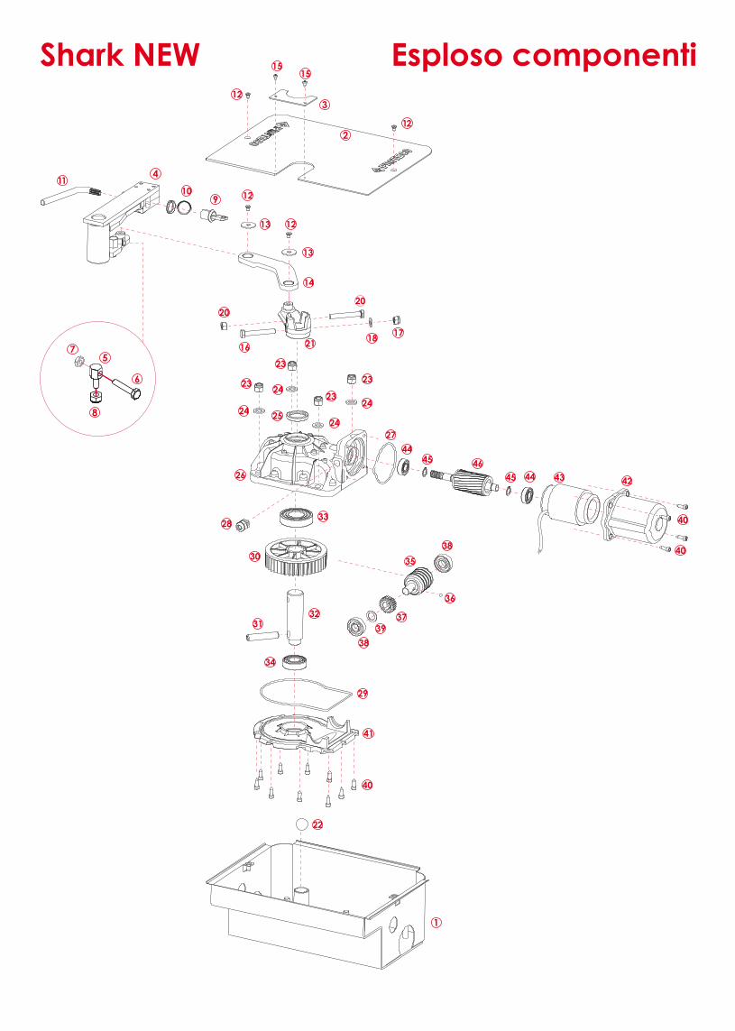
Esploso componentiShark NEW 01 MSHCF01 Cassetta di fondazione cataforesi 02 SSHCCF0170 Coperchio zinc. Proteco per cassetta fondazione 03 SSHCCCF0170 Chiusura post. Coperchio zincata 04 SSHSASB01 Supporto anta + disp. Sblocco completo 05 MSHFA02 Fermo apertura zincato 06 MVI1035AZ Vite TE 10x35 tot. Fil. Zinc. -UNI5793- 07 MDAM10Z Dado M10 zinc. -UNI 5588- normale 08 MDAM12AB Dado M12 autobloccante zinc. Basso DIN 985 09 MNO06 Nottolino sblocco per SHARK 10 MTP20 Tappo copertura serratura SHARK 11 SCH0570 Chiave sblocco zincata 12 MVI0610FI Vite TPSCEI 6X10 inox -UNI5933- 13 MRO0832Z Rondella 8x32 zinc. 14 SSHLT0190 Leva di trasmissione nita 15 MVI3595D Vite TC autobloccante 3,5x9,5 -UNI6954- 16 MVI1070AZ Vite TE 10x70 P.F. Zinc. -UNI5737- 17 MDAM10AA Dado M10 autobloccante zinc. Alto DIN 982 18 MRO10Z Rondella Ø10 zinc. -UNI6592- 19 MVI1070AZ2 Vite TE 10x70 T.F. Zinc. -UNI5739- 20 MDAM10AA Dado M10 autob. Zinc. Alto DIN 982 21 SSHBI0170 Biella zincata per interrato 22 MSF25 Sfera Ø25,4 (1 pollice) inox 23 MDAM12AA Dado M12 autobl. Zinc. Alto DIN 982 24 MRO12Z Rondella Ø 12x24 zinc. -UNI6592- 25 MPA35477 Paraolio 35/47/7 doppio labbro
26 SCRSHS45 Corpo riduttore superiore lav. interr. 27 MOR4337 O.R. 4337 per calotta Shark 28 MPC04 Passacavo in plastica Shark 29 MOR4700 O.R.4700 177,4x3,5 riduttore Shark 30 MSHZ01 Ingranaggio zama M3 Z43 31 MSP1470 Spina elastica 14x70 -UNI6873- 32 SALU0370 Albero uscita Shark zincato 33 MCU6207 Cuscinetto 6207 2RS 34 MCU6205 Cuscinetto 6205 35 SALS0220 Albero secondario con nicchia Shark 36 MSF06 Sfera Ø6 inox 37 SRBB30 Ruota bronzo per blocco dentata brocciata 38 MCU7203 Cuscinetto 7203 39 MSDS1725 Distanziale 17x25x2 Shark 40 MVI6319CI Vite TCE 6,3x19 autol. inox 41 MFCRSHI Coperchio inf. ridutt. interr. 42 MFCAA03 Calotta all. interrato 43 SST41470L Statore 230V 1400g. - 4 p-h70 c. Lungo 44 MCU6202 Cuscinetto 6202 ZZ per motori elettr. 45 MSE15 Seeger E15x1,5 46 SALBSH7010 Albero bloccato con rotore H70 Shark MCO10C Condensatore 10µF 450V MSC72 Scatola motore Shark MSC73 Scatola casseta di fondazione Shark
Esploso componentiShark NEW
11
18
22
30
31
10
3
1
4
2
5
6
7
8
9
12
13
14
15
16
1721
23
25
29
28
27
12
24
20
20
32
26
34
33
13
12
24
24
24
15
23
23
23
12
35
36
38
38
39
37
41
40
43
44
4645
45 44 42
40
40