ROMANI GROUP - trivenetaimpianti.com LAMIERA.pdf · zature per presse piegatrici ed oggi, ... nella...
56
ROMANI GROUP LAVORAZIONE LAMIERA Sheet Metal Working
Transcript of ROMANI GROUP - trivenetaimpianti.com LAMIERA.pdf · zature per presse piegatrici ed oggi, ... nella...
RO
MA
NI G
RO
UP
LAVORAZIONE LAMIERA
Sheet Metal Working
La realizzazione del presente catalogo è avvenuta nel controllo più rigoro-so dei dati in esso contenuti. L'eventuale presenza di errori ed omissioninon è pertanto in alcun modo riconducibile a nostre responsabilità. Inseguito alla costante evoluzione tecnica dei nostri prodotti, ci riserviamoil diritto di effettuare modifiche anche parziali.Tutti i diritti sono riservati.La riproduzione, anche parziale, non è ammessa senza nostra autorizzazione.
Every care has been taken to ensure the accuracy of the informationcontained in this catalogue and no liability can be accepted for anyerrors or omissions. The right is reserved to make changes, evenpartial ones, necessitated by technological developments on ourproducts. All right reserved. This book or part thereof may not be reproduced without our permission.
4 PRESENTAZIONE
5 DETTAGLI TECNICI
6 UTENSILI STANDARD
24 CONTRO “V” A DISEGNO
26 MATRICI A DISEGNO
29 ATTREZZATURE SPECIALI
44 INTERMEDIARI
47 MATRICI VARIO “V”
49 TAVOLE DI COMPENSAZIONE
51 LAME LINEARI
53 CERTIFICAZIONE
54 RICHIESTA DI OFFERTA
4 PRESENTATION
5 TECHNICAL DETAILS
6 STANDARD TOOLS
24 SPECIAL PUNCHES
26 SPECIAL DIES
29 SPECIAL EQUIPMENTS
44 CLAMPING ELEMENTS
47 VARIABLE “V” DIES
49 DEFLECTION COMPENSATION TABLES
51 LINEAR BLADES
53 CERTIFICATION
55 INQUIRY
INDICE / INDEX
( )4
PRESENTAZIONE / PRESENTATION
Capofila delle aziende affiliate a ROMANI GROUP,la società ANGELO ROMANI ha intrapreso da diversianni un percorso di continuo sviluppo ed innovazionemigliorando ed ampliando la propria gamma di prodottie servizi.
Mantenendo come obiettivo la massima soddisfazione diuna clientela sempre più esigente, l’azienda ha rinnovatola sua proposta anche nel settore degli utensili ed attrez-zature per presse piegatrici ed oggi, oltre a mantenere lostatus di leader nella costruzione di punzoni e matrici spe-ciali a disegno, presenta la serie di utensili “standard”descritti in catalogo garantendo l’alta qualità, che con-traddistingue tutti i nostri prodotti, e la disponibilità amagazzino per pronta consegna.
La pluriennale esperienza nel settore del presse piegatri-ci, permette altresì al personale tecnico della societàANGELO ROMANI di studiare e progettare stampi spe-ciali in accordo con le personali esigenze dei clienti. Questo servizio che l’azienda propone ha come obiettivofinale la fornitura di un prodotto che consenta al clientedi abbattere i tempi di produzione riducendo al massimoil numero di colpi necessari per ottenere la piegaturadesiderata.
UTENSILI STANDARD
Costruiti in acciaio C45 bonificato, temprati e rettificati, gli
utensili standard ROMANI sono accuratamente eseguiti garan-
tendo precisione, lunga durata e integrità della superficie del
materiale lavorato.
Le lunghezze degli utensili disponibili a magazzino sono:
- 835 mm.
- 415 mm.
- frazionato (vedi catalogo a pag. 21)
L’intercambiabilità è garantita solo tra utensili nuovi e di nostra
produzione. Non possiamo garantire l’accoppiamento con uten-
sili usurati o prodotti da altre aziende.
L’ausilio di impianti C.N.C. aggiornati alla tecnologia più progre-
dita e personale altamente specializzato costituiscono la miglior
referenza del prodotto.
The first of the Companies to be affiliated into the independent
ROMANI GROUP was the ANGELO ROMANI Organisation
which for many years has undertaken a continuous plan of deve-
lopment, improvement and expansion of its innovative product
range and services.
Continuing our objective to maintain and give maximum satisfac-
tion for all our customer demands, the Company’s ongoing policy
is for being the leader in the field of designer manufacture in
specialist tools and equipment for press brake machines and
special purpose punches and dies. We have introduced the
standard tool series described in this catalogue and like all our
products are manufactured and guaranteed to the highest qua-
lity along with our availability to carry stock for immediate deli-
very.
Our long experience in the field of press brake machines allows
ANGELO ROMANI’s highly trained technical staff to work with
customer requirements in the study and planning of special pur-
pose equipment.
Our final objective is to work with the customer in supplying a
product that reduces to the minimum the number of movements
necessary to obtain the desired profile.
STANDARD TOOLS
Manufactured in C45 steel, hardened and ground, the
ROMANI standard tools are accurately machined guaranteeing
precision, long life and unity to the surface of the worked metal.
The lengths of the tools available from our stock are as follows:
- 835 mm.
- 415 mm.
- sectioned (see the catalogue on page 21)
Interchangeability is only guarenteed between new tools of our
production. We cannot guarantee perfect fit with worn tools or
tools manufactured by other companies.
State-of-the-art C.N.C. machinery and highly skilled personnel
are used to manufacture these products.
( )5
DETTAGLI TECNICI / TECHNICAL DETAILS
Nell’impiego degli stampi occorre tenere presentequanto segue:
1. Ogni stampo è costruito per lavorare lamiere fino ad unospessore ben determinato.2. Impiegando lamiere di spessore inferiore a quello per cuigli stampi sono stati costruiti, non si otterrà un lavoro con laprecisione desiderata.3. Impiegando lamiere di spessore superiore, oltre a nonottenere la precisione desiderata, si eserciteranno suglistampi delle componenti laterali, un forte logorio di eventua-li spigoli vivi o addirittura gravi danni alle attrezzature stesse.4. Inoltre gli sforzi di lavoro previsti potrebbero aumentareenormemente portando ad eventuali laminazioni del materia-le dovute alla relativa insufficienza dei giochi.5. Alcune esecuzioni di stampi sono consigliate fino a deter-minati spessori, oltre i quali si dovrà ricorrere ad altra ese-cuzione.6. Nella progettazione di stampi muniti di estrattori a molleè consigliabile, per quanto possibile, agganciare la matricenella parte superiore della pressa piegatrice, capovolgendolo stampo ed evitando che le molle si incrostino di scaglie diossido o di sporcizia; in tal modo si allunga anche la vita dellostampo.7. Un fattore che incide sulla precisione del lavoro è il ritor-no elastico del materiale, che negli stampi deve essere com-pensato a priori.8. Questa compensazione non è facilmente determinabile,in quanto, ogni materiale ha la sua elasticità che può varia-re anche da fornitura a fornitura.9. Nelle piegature a raggio è necessario considerare quan-to segue: quando il raggio supera 4 volte la dimensione dellospessore della lamiera si verifica un ritorno elastico, cheaumenta con l’aumentare del raggio stesso.
MODALITA’ DI APPLICAZIONE DEGLI SFORZIDurante le operazioni di piegatura della lamiera mediantel’ausilio delle presse piegatrici idrauliche, è preferibile appli-care gli sforzi di lavoro al centro delle stesse.
a) Centratura longitudinale.Riferendosi alla lunghezza del bancale, gli sforzi devono esse-re uniformemente distribuiti su tutta la lunghezza oppureapplicati nel centro.
b) Centratura trasversalePur supportando notevoli sollecitazioni trasversali, anchenelle presse piegatrici idrauliche occorre rispettare, perquanto possibile, la regola generale di applicazione degli sfor-zi al centro.
Se per necessità di lavoro l’applicazione degli sforzi nondovesse avvenire in centro, occorrerebbe costruire gli stam-pi al fine di assorbire le relative componenti laterali.
When using press-brake machines the followingshould be observed:
1. Every tool is specially manufactured to enable it to worksheets within its boundaries.2. Using sheets that are outside the boundaries for whichthe tool has been manufactured will result in inaccuracies.3. Using sheets of larger thickness with the incorrect too-ling will again result in inaccuracies leading to lateral move-ment, excessive wear and eventually sharp corners or quiteserious damage to the tools.4. Incorrect clearances will considerably increase the effortrequired to press the worksheets.5. Tooling will require to be altered if used for other than itsrecommendation.6. In the assembly of tools it is advisable, where possible,to hook the die in the upper part of the press-brake machi-ne, turning over the tools and avoiding the fouling and theoxidization of the springs therefore prolonging the life of thetools.7. A factor that will affect the precision of the job is thespring back of the material. Compensation to the toolingmust be made to allow for this.8. It is not easy to determine this compensation, as springback may alter from material to material.9. In the radius bending it is necessary to consider the fol-lowing:when the radius exceeds four times the dimension of thesheet thickness, a spring back occurs that increases withincreasing of the same radius.
METHOD OF APPLICATIONWhen utilising hydraulic press-brake machines for sheetmetal bending applications, the general rule is for the forceto applied to the centre.
a) Longitudinal truingIn reference to the length of the bench, the force must bedistributed in a uniform method on all the length or appliedin the centre.
b) Cross truingIn support of the hydraulic press-brake machine the generalrule is for the force to be applied to the centre.
If the force is not applied to the centre the tools must be pro-duced with an aim to absorbing the lateral movement.
( )6
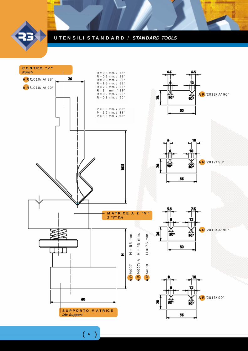
AR/2012/A/90°
AR/2012/90°
AR/2013/A/90°
AR/2013/90°
AR/1010/A/88°
AR/1010/A/90°
MATRICE A 2 “V”2 “V” Die
SUPPORTO MATRICEDie Support
AR
/40
07
H
= 5
5 m
m.
AR
/4007/
A
H =
45 m
m.
AR
/40
08
H
= 7
5 m
m.
CONTRO “V”Punch R = 0.8 mm. / 75°
R = 0.2 mm. / 88°R = 0.8 mm. / 88°R = 1.5 mm. / 88°R = 2.3 mm. / 88°R = 3 mm. / 88°R = 0.2 mm. / 90°R = 0.8 mm. / 90°
P = 0.8 mm. / 88°P = 2.9 mm. / 88°P = 0.8 mm. / 90°
UTENSILI STANDARD / STANDARD TOOLS
( )7
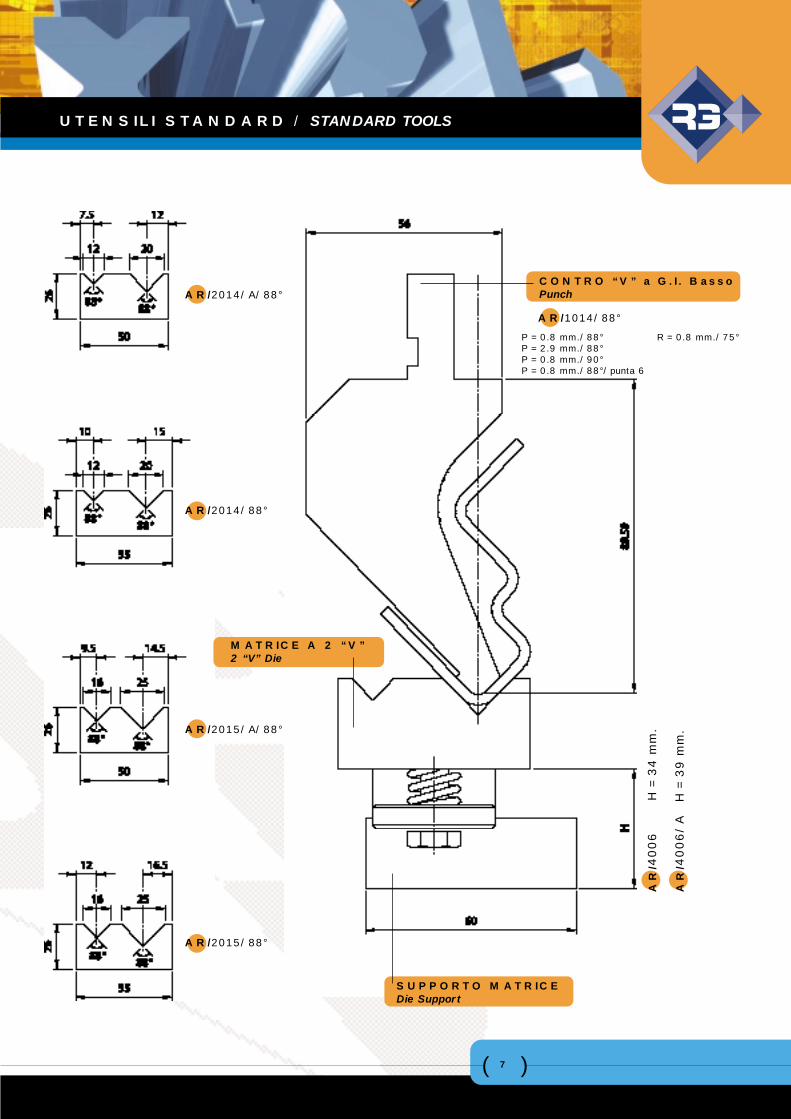
AR/2014/A/88°
AR/2014/88°
AR/2015/A/88°
AR/2015/88°
MATRICE A 2 “V”2 “V” Die
SUPPORTO MATRICEDie Support
AR
/40
06
H
= 3
4 m
m.
AR
/4006/
A
H =
39 m
m.
CONTRO “V” a G.I. BassoPunch
P = 0.8 mm./88°P = 2.9 mm./88°P = 0.8 mm./90°P = 0.8 mm./88°/punta 6
R = 0.8 mm./75°
AR/1014/88°
UTENSILI STANDARD / STANDARD TOOLS
( )8
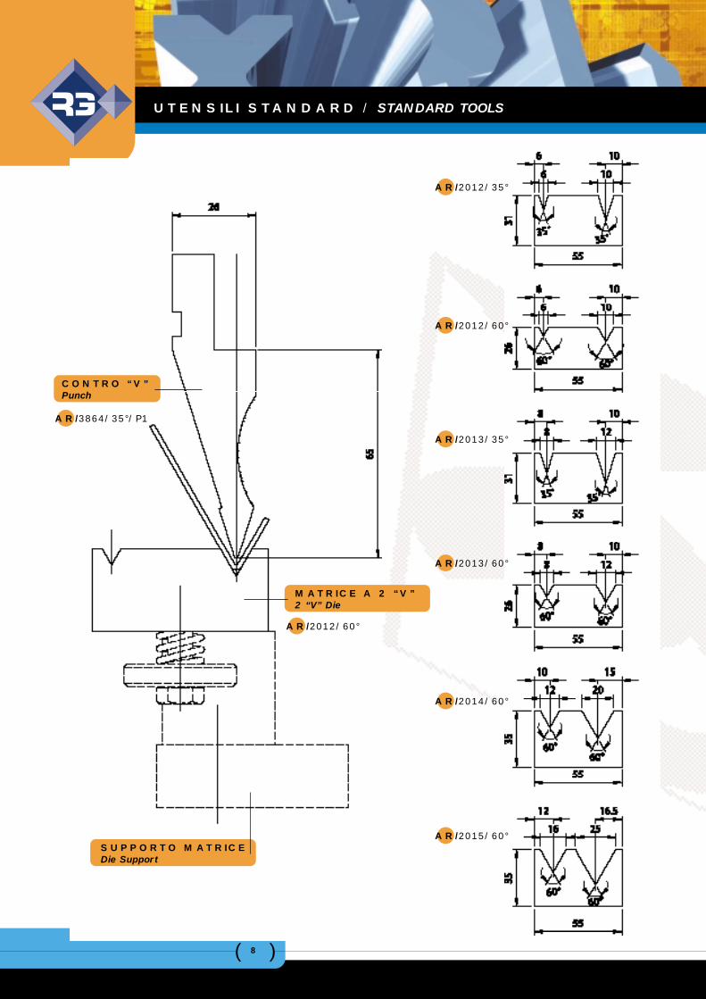
AR/2012/35°
AR/2012/60°
AR/2013/35°
AR/2013/60°
AR/2014/60°
AR/2015/60°
CONTRO “V”Punch
AR/3864/35°/P1
MATRICE A 2 “V”2 “V” Die
AR/2012/60°
SUPPORTO MATRICE Die Support
UTENSILI STANDARD / STANDARD TOOLS
( )9
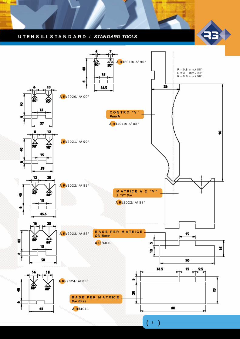
AR/2019/A/90°
AR/2020/A/90°
AR/2021/A/90°
CONTRO “V” Punch
AR/1019/A/88°
R = 0.8 mm./88°R = 3 mm./88°R = 0.8 mm./90°
MATRICE A 2 “V”2 “V” Die
AR/2022/A/88°
BASE PER MATRICEDie Base
AR/4010
AR/2022/A/88°
AR/2023/A/88°
AR/2024/A/88°
BASE PER MATRICEDie Base
AR/4011
UTENSILI STANDARD / STANDARD TOOLS
( )10
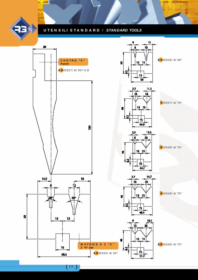
CONTRO “V”Punch
AR/1027/A/30°/0.8
AR/2026/A/30°
AR/2027/A/75°
AR/2028/A/75°
AR/2029/A/75°
AR/2030/A/75°MATRICE A 2 “V”2 “V” Die
AR/2025/A/30°
UTENSILI STANDARD / STANDARD TOOLS
( )11
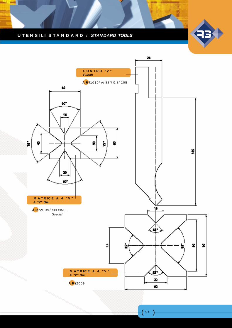
CONTRO “V”Punch
MATRICE A 4 “V”4 “V” Die
AR/1010/A/88°/0.8/105
AR/2009
AR/2009/SPECIALESpecial
MATRICE A 4 “V”4 “V” Die
UTENSILI STANDARD / STANDARD TOOLS
( )12
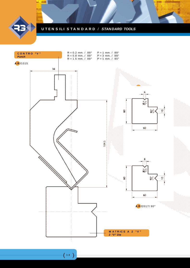
R = 0.2 mm. / 88°R = 0.8 mm. / 88°R = 1.5 mm. / 88°
P = 1 mm. / 88°P = 3 mm. / 88°P = 1 mm. / 90°
MATRICE A 2 “V”2 “V” Die
AR/2016/90°
AR/2017/90°
CONTRO “V”Punch
AR/1015
UTENSILI STANDARD / STANDARD TOOLS
( )13
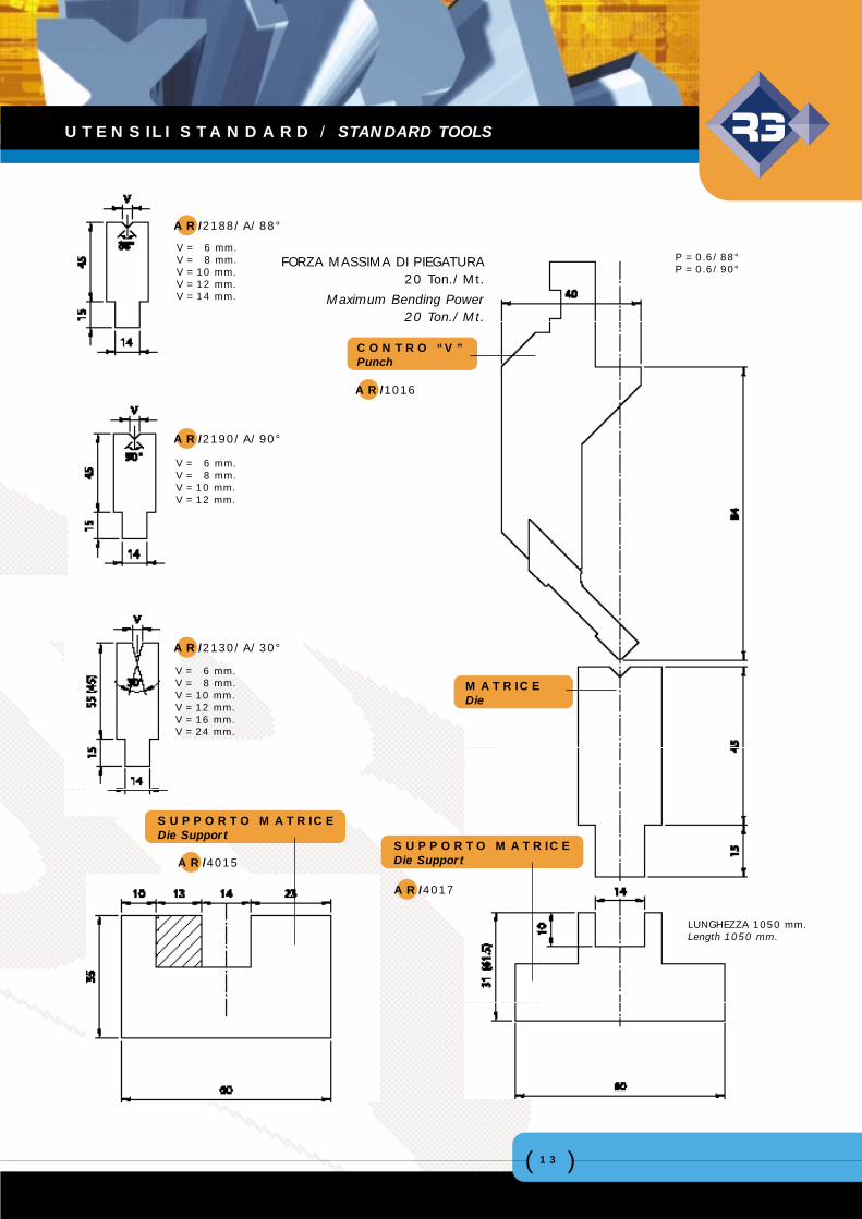
AR/2188/A/88°
AR/2190/A/90°
AR/2130/A/30°
AR/4015
CONTRO “V”Punch
MATRICEDie
SUPPORTO MATRICE Die Support
FORZA MASSIMA DI PIEGATURA20 Ton./Mt.
Maximum Bending Power20 Ton./Mt.
V = 6 mm.V = 8 mm.V = 10 mm.V = 12 mm.V = 16 mm.V = 24 mm.
V = 6 mm.V = 8 mm.V = 10 mm.V = 12 mm.
V = 6 mm.V = 8 mm.V = 10 mm.V = 12 mm.V = 14 mm.
SUPPORTO MATRICE Die Support
LUNGHEZZA 1050 mm.Length 1050 mm.
P = 0.6/88°P = 0.6/90°
AR/1016
AR/4017
UTENSILI STANDARD / STANDARD TOOLS
( )14
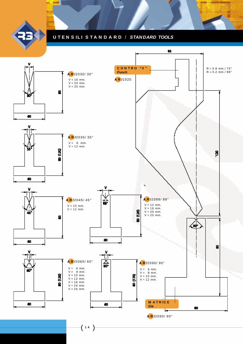
CONTRO “V”PunchAR/2030/30°
AR/2035/35°
AR/2045/45° AR/2088/88°
AR/2060/60° AR/2090/90°
AR/2090/90°
MATRICEDie
V = 16 mm.V = 20 mm.V = 25 mm.
V = 8 mm.V = 12 mm.
V = 12 mm.V = 16 mm.V = 20 mm.V = 25 mm.
V = 6 mm.V = 8 mm.V = 10 mm.V = 12 mm.
V = 6 mm.V = 8 mm.V = 10 mm.V = 12 mm.V = 16 mm.V = 20 mm.V = 25 mm.
AR/1020
V = 10 mm.V = 12 mm.
R = 0.8 mm./75°R = 0.2 mm./88°
UTENSILI STANDARD / STANDARD TOOLS
( )15
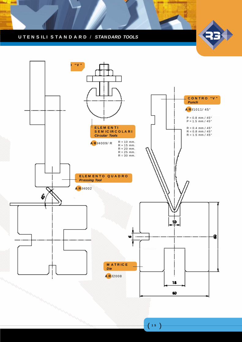
CONTRO “V”Punch
AR/4005
CONTRO “V”Punch
AR/1011/45°
P = 0.8 mm./45°P = 1.5 mm./45°
R = 0.4 mm./45°R = 0.8 mm./45°R = 1.5 mm./45°
R = 10 mm.R = 15 mm.R = 20 mm.R = 25 mm.R = 30 mm.
ELEMENTISEMICIRCOLARICircular Tools
AR/4009/R
AR/2008
MATRICEDie
ELEMENTO QUADROPressing Tool
AR/4002
UTENSILI STANDARD / STANDARD TOOLS
( )16
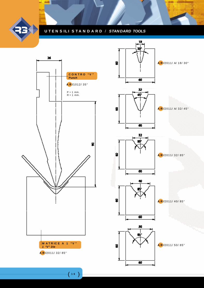
AR/2011/A/18/30°
AR/2011/A/32/45°
AR/2011/32/85°
AR/2011/40/85°
AR/2011/50/85°
CONTRO “V”Punch
AR/1012/35°
MATRICE A 1 “V”1 “V” Die
AR/2011/32/85°
P = 1 mm.R = 1 mm.
UTENSILI STANDARD / STANDARD TOOLS
( )17
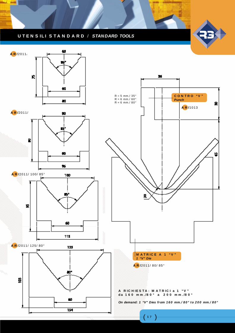
MATRICE A 1 “V”1 “V” Die
AR/2011/80/85°
CONTRO “V”Punch
AR/1013
AR/2011/63/85°
AR/2011/80/85°
AR/2011/100/85°
AR/2011/125/80°
A RICHIESTA: MATRICI a 1 “V”da 160 mm./80° a 200 mm./80°
On demand: 1 “V” Dies from 160 mm./80° to 200 mm./80°
R = 5 mm./35°R = 6 mm./60°R = 6 mm./80°
UTENSILI STANDARD / STANDARD TOOLS
( )18
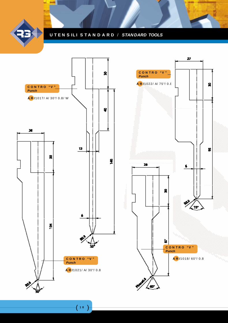
CONTRO “V”Punch
AR/1021/A/30°/0.8
CONTRO “V”Punch
AR/1017/A/30°/0.8/W
CONTRO “V”Punch
AR/1022/A/75°/0.8
CONTRO “V”Punch
AR/1018/60°/0.8
UTENSILI STANDARD / STANDARD TOOLS
( )19
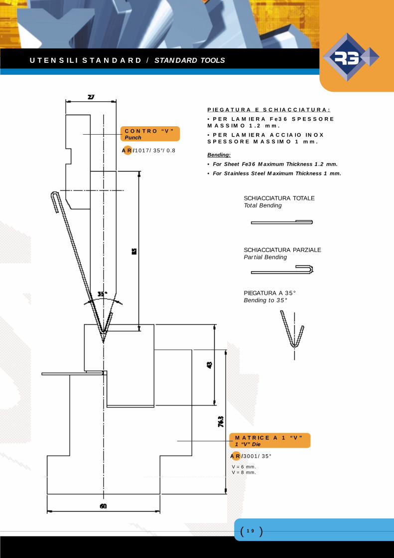
CONTRO “V”Punch
AR/1017/35°/0.8
MATRICE A 1 “V”1 “V” Die
AR/3001/35°
PIEGATURA E SCHIACCIATURA:
• PER LAMIERA Fe36 SPESSOREMASSIMO 1.2 mm.
• PER LAMIERA ACCIAIO INOXSPESSORE MASSIMO 1 mm.
Bending:
• For Sheet Fe36 Maximum Thickness 1.2 mm.
• For Stainless Steel Maximum Thickness 1 mm.
SCHIACCIATURA TOTALETotal Bending
SCHIACCIATURA PARZIALEPartial Bending
PIEGATURA A 35°Bending to 35°
V = 6 mm.V = 8 mm.
UTENSILI STANDARD / STANDARD TOOLS
( )20
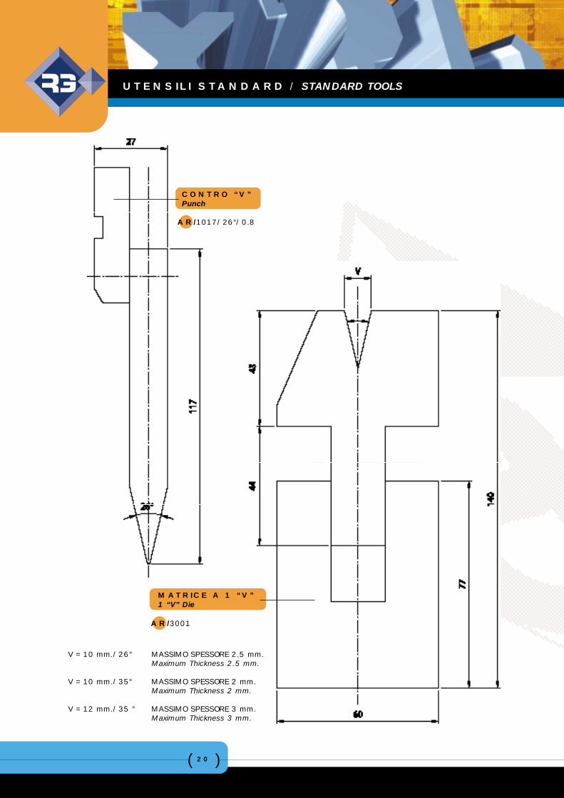
CONTRO “V”Punch
AR/1017/26°/0.8
MATRICE A 1 “V”1 “V” Die
AR/3001
V = 10 mm./26° MASSIMO SPESSORE 2.5 mm.Maximum Thickness 2.5 mm.
V = 10 mm./35° MASSIMO SPESSORE 2 mm.Maximum Thickness 2 mm.
V = 12 mm./35 ° MASSIMO SPESSORE 3 mm.Maximum Thickness 3 mm.
UTENSILI STANDARD / STANDARD TOOLS
( )21
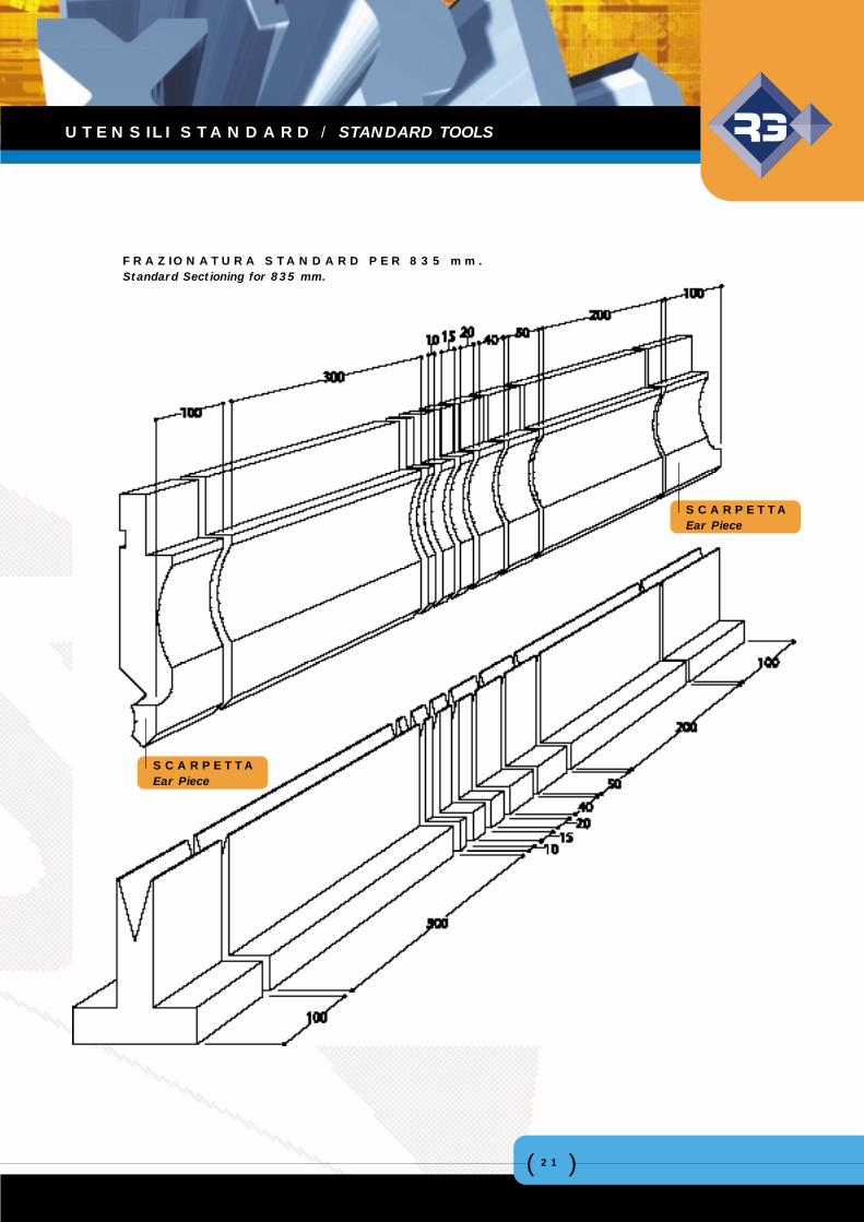
FRAZIONATURA STANDARD PER 835 mm.Standard Sectioning for 835 mm.
SCARPETTAEar Piece
SCARPETTAEar Piece
UTENSILI STANDARD / STANDARD TOOLS
( )22
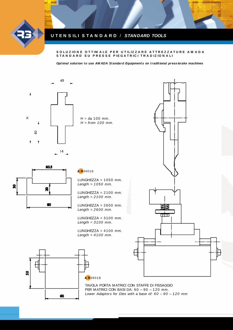
SOLUZIONE OTTIMALE PER UTILIZZARE ATTREZZATURE AMADASTANDARD SU PRESSE PIEGATRICI TRADIZIONALI
Optimal solution to use AMADA Standard Equipments on traditional press-brake machines
AR/4018
AR/4016
LUNGHEZZA = 1050 mm.Length = 1050 mm.
LUNGHEZZA = 2100 mm.Length = 2100 mm.
LUNGHEZZA = 2600 mm.Length = 2600 mm.
LUNGHEZZA = 3100 mm.Length = 3100 mm.
LUNGHEZZA = 4100 mm.Length = 4100 mm.
H = da 100 mm.H = from 100 mm.
TAVOLA PORTA MATRICI CON STAFFE DI FISSAGGIOPER MATRICI CON BASI DA: 60 – 90 – 120 mm.Lower Adaptors for Dies with a base of: 60 – 90 – 120 mm
UTENSILI STANDARD / STANDARD TOOLS
( )23
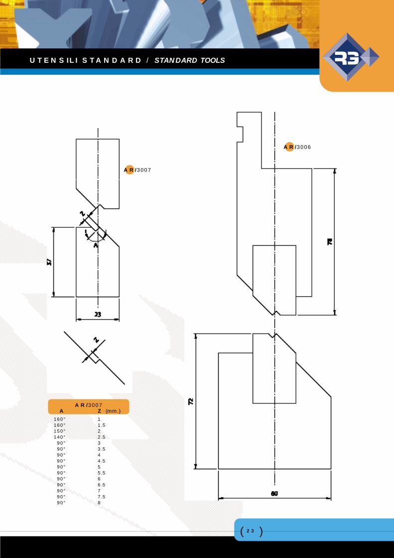
AR/3007
AR/3006
A Z (mm.)160° 1160° 1.5150° 2140° 2.590° 390° 3.590° 490° 4.590° 590° 5.590° 690° 6.590° 790° 7.590° 8
AR/3007
UTENSILI STANDARD / STANDARD TOOLS
( )24
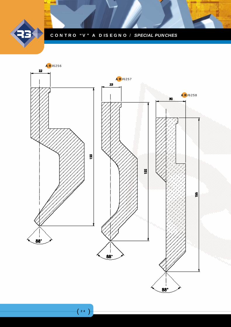
AR/6256
AR/6257
AR/6258
CONTRO “V” A DISEGNO / SPECIAL PUNCHES
( )25
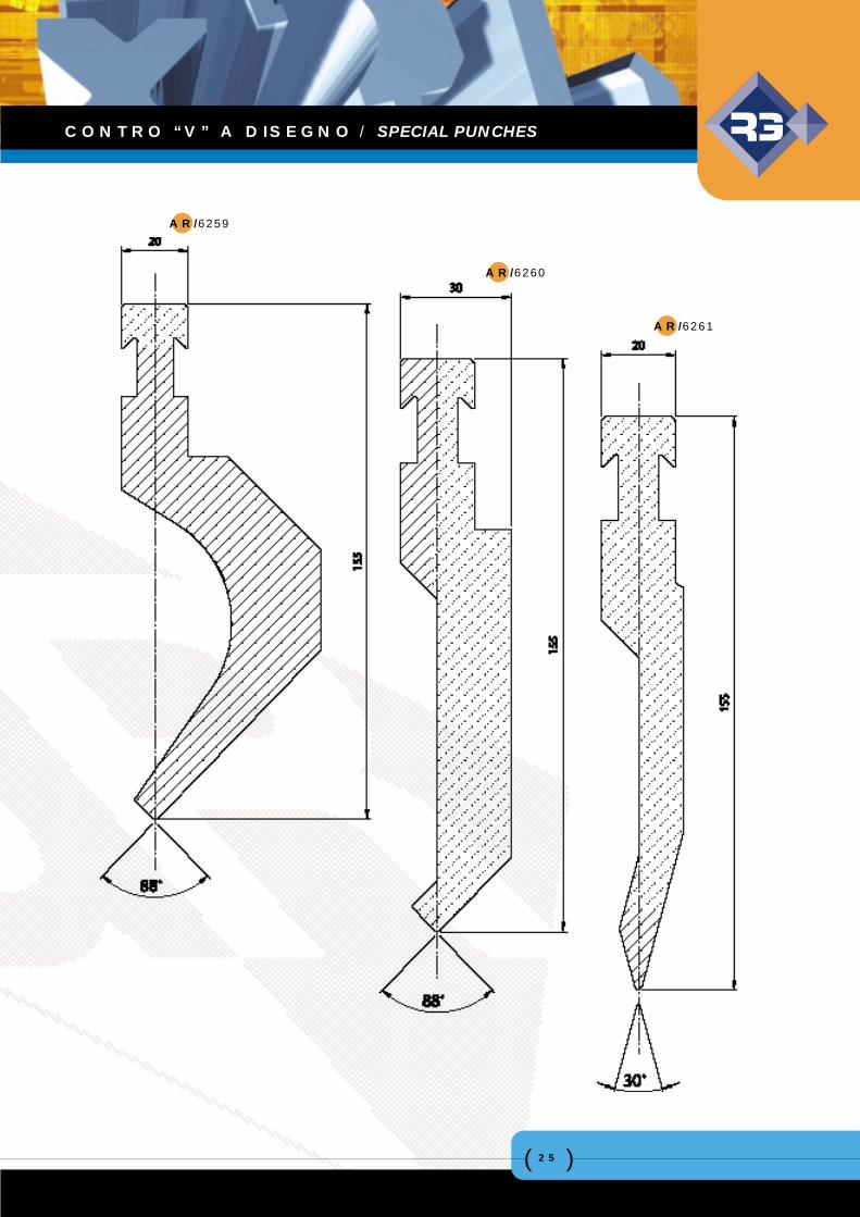
AR/6259
AR/6260
AR/6261
CONTRO “V” A DISEGNO / SPECIAL PUNCHES
( )26
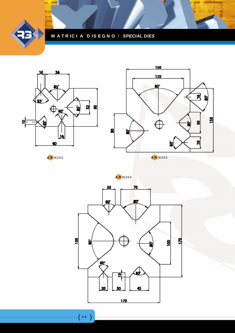
AR/6262 AR/6263
AR/6264
MATRICI A DISEGNO / SPECIAL DIES
( )27
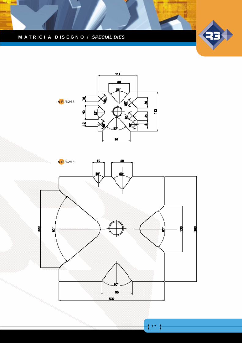
AR/6265
AR/6266
MATRICI A DISEGNO / SPECIAL DIES
( )28
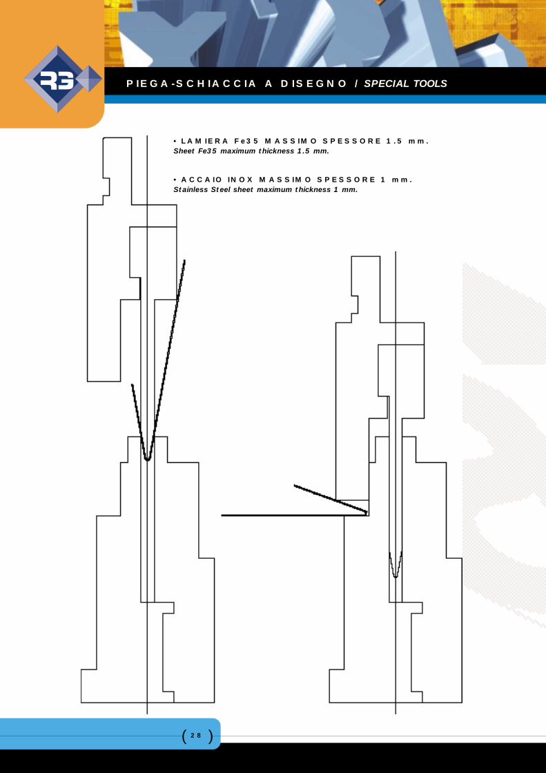
• LAMIERA Fe35 MASSIMO SPESSORE 1.5 mm.Sheet Fe35 maximum thickness 1.5 mm.
• ACCAIO INOX MASSIMO SPESSORE 1 mm.Stainless Steel sheet maximum thickness 1 mm.
PIEGA-SCHIACCIA A DISEGNO / SPECIAL TOOLS
( )29
La società ANGELO ROMANI, avvalendosi dei pro-pri tecnici con pluriennale esperienza di settore, èin grado di progettare e realizzare attrezzatturespeciali per presse piegatrici in accordo con le par-ticolari esigenze di ogni singolo cliente.
Gli impianti di cui dispone l’azienda permettono diprodurre attrezzature con lunghezza fino a 11metri.
Per raggiungere l’obiettivo di fornire un prodotto dialta qualità, l’azienda esige, già dall’acquisto dellamateria prima, una certificazione che continuerà adessere integrata durante tutto il ciclo di produzione.
La costruzione di uno stampo speciale, comunque,è sempre subordinata al tipo di lamiera che deveessere piegata ed al suo ritorno elastico.E’ per questo motivo che prima della consegna defi-nitiva, un campione dell’attrezzatura costruita verràcollaudato in collaborazione con il Cliente presso laSua sede verificando che le esigenze produttive ven-gano totalmente soddisfatte.
The Company, ANGELO ROMANI, have their ownteam of highly qualified and skilled Technicians withmany years experience in working with all customerrequirements on both planning and producingspecial equipment for press-brake machinery.
Lengths of up to 11 mt. can be manufactured byour skilled Production Team.
The raw materials that are used in the manufactureof special equipment are of the highest quality andare only purchased from reputable manufacturersand suppliers accompanied by full material analysiscertification. As part of our quality assurance thesteel analysis certificate is integrated into ourproduction and manufacturing systems.
Depending on the type of sheet that requiresbending and its spring back our special equipmentis produced accordingly and to allow for thesefactors.Customer satisfaction is paramount at all times andbefore dispatch we invite them to test a sample andto confirm acceptance of the special equipment pro-duced to our exacting standards.
ATTREZZATURE SPECIALI / SPECIAL EQUIPMENTS
( )30
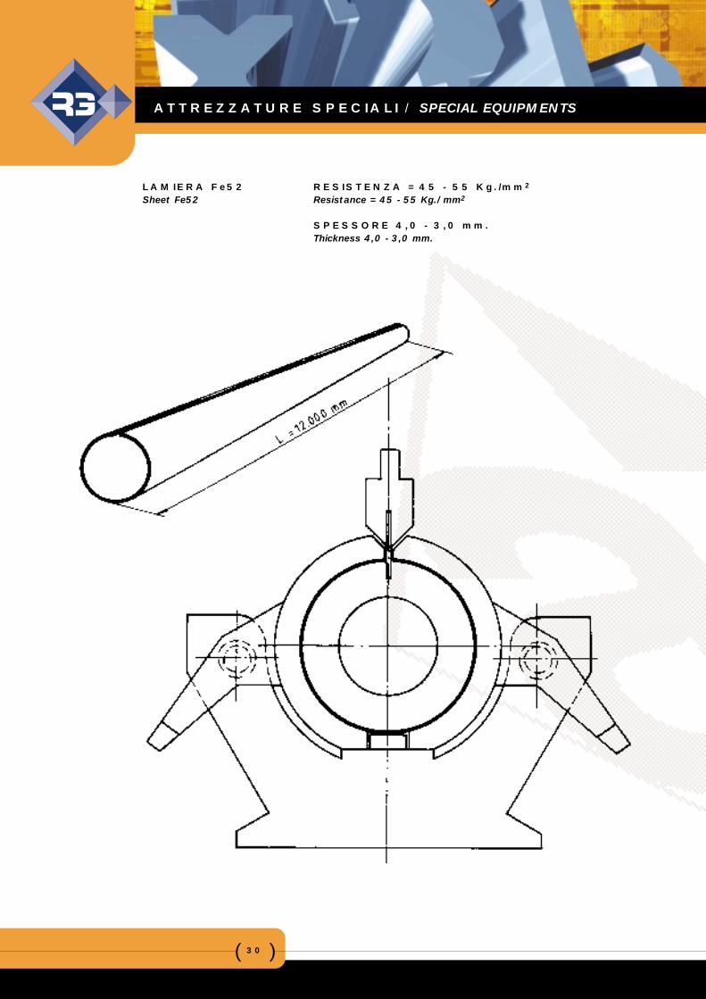
LAMIERA Fe52 RESISTENZA = 45 - 55 Kg./mm2
Sheet Fe52 Resistance = 45 - 55 Kg./mm2
SPESSORE 4,0 - 3,0 mm.Thickness 4,0 - 3,0 mm.
ATTREZZATURE SPECIALI / SPECIAL EQUIPMENTS
( )31
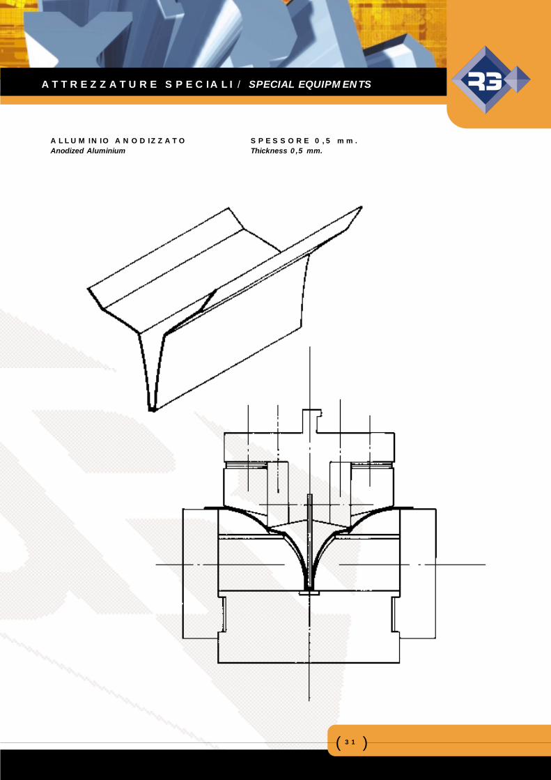
ALLUMINIO ANODIZZATO SPESSORE 0,5 mm.Anodized Aluminium Thickness 0,5 mm.
ATTREZZATURE SPECIALI / SPECIAL EQUIPMENTS
( )32
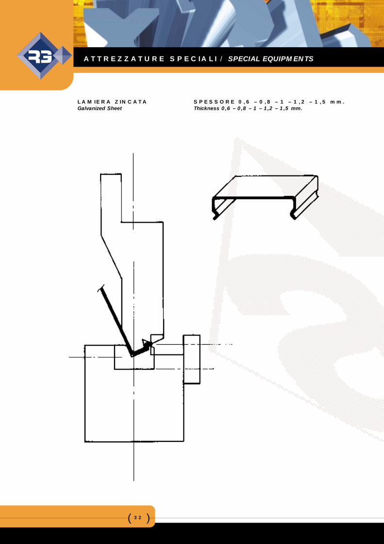
LAMIERA ZINCATA SPESSORE 0,6 – 0,8 – 1 – 1,2 – 1,5 mm.Galvanized Sheet Thickness 0,6 – 0,8 – 1 – 1,2 – 1,5 mm.
ATTREZZATURE SPECIALI / SPECIAL EQUIPMENTS
( )33
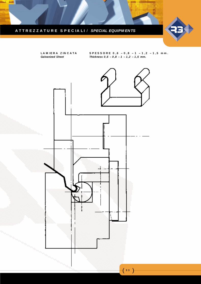
LAMIERA ZINCATA SPESSORE 0,6 – 0,8 – 1 – 1,2 – 1,5 mm.Galvanized Sheet Thickness 0,6 – 0,8 – 1 – 1,2 – 1,5 mm.
ATTREZZATURE SPECIALI / SPECIAL EQUIPMENTS
( )34
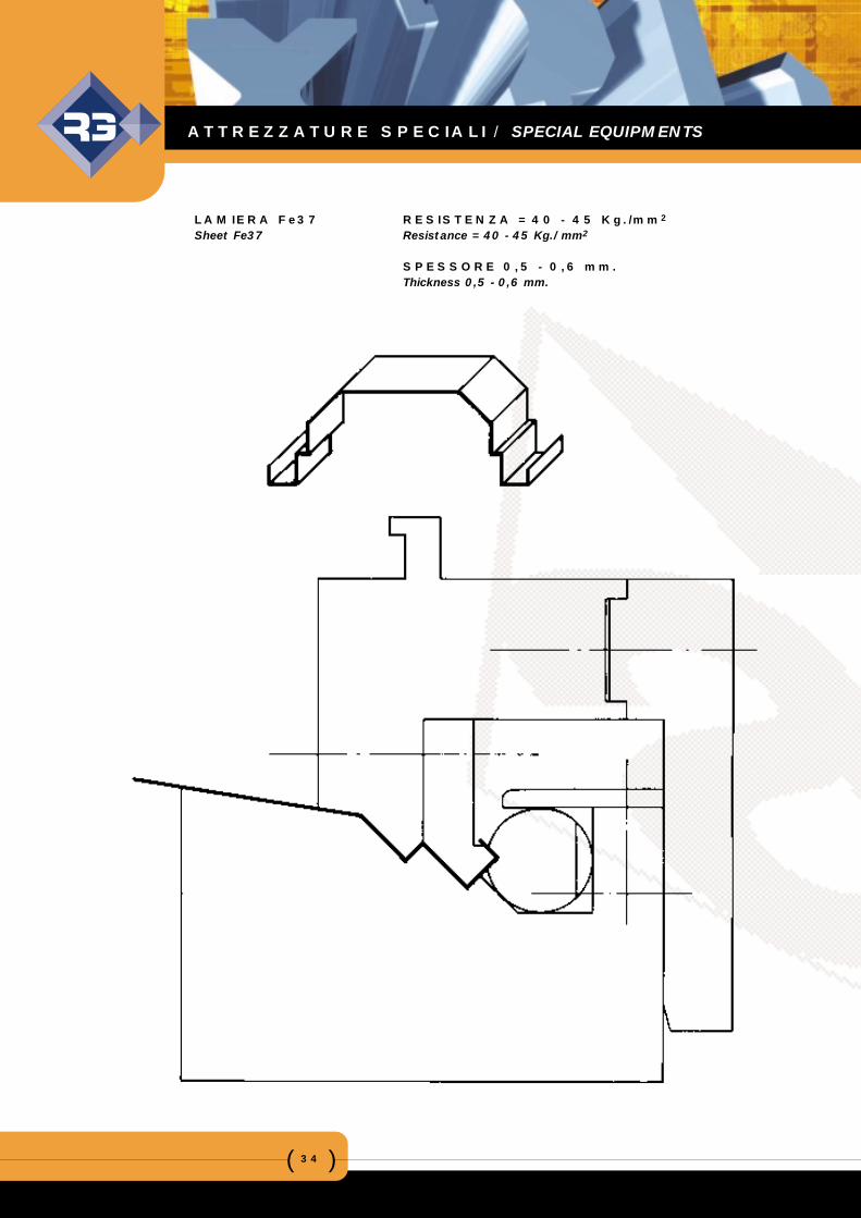
LAMIERA Fe37 RESISTENZA = 40 - 45 Kg./mm2
Sheet Fe37 Resistance = 40 - 45 Kg./mm2
SPESSORE 0,5 - 0,6 mm.Thickness 0,5 - 0,6 mm.
ATTREZZATURE SPECIALI / SPECIAL EQUIPMENTS
( )35
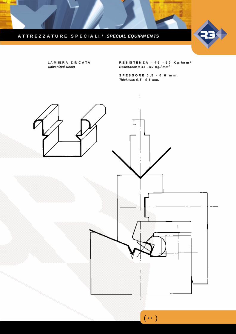
LAMIERA ZINCATA RESISTENZA = 45 - 50 Kg./mm2
Galvanized Sheet Resistance = 45 - 50 Kg./mm2
SPESSORE 0,5 - 0,6 mm.Thickness 0,5 - 0,6 mm.
ATTREZZATURE SPECIALI / SPECIAL EQUIPMENTS
( )36
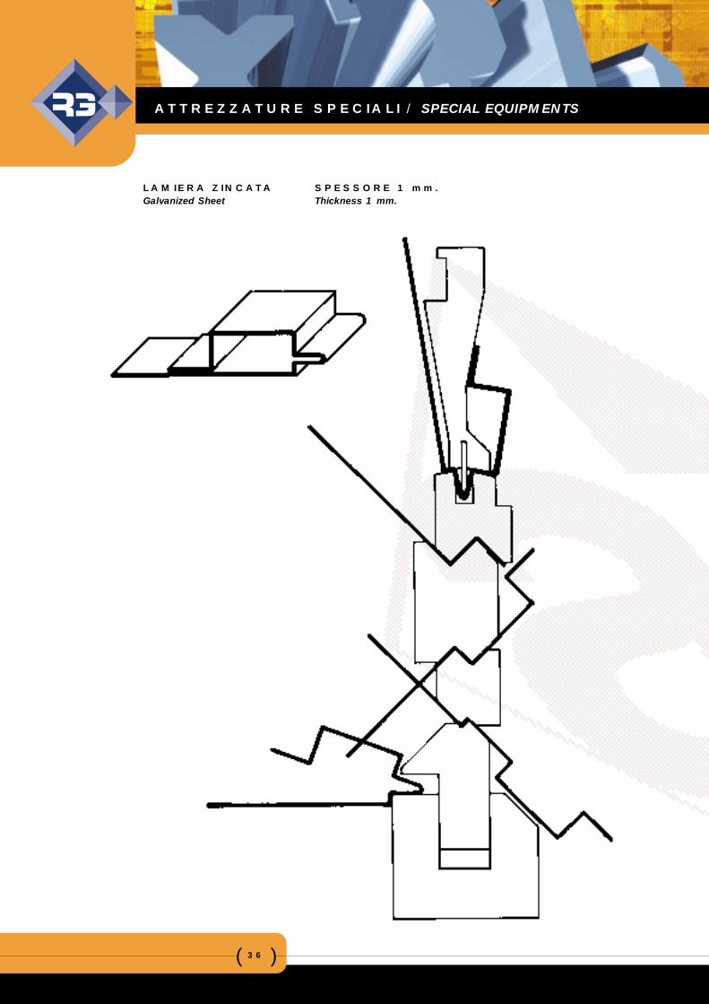
LAMIERA ZINCATA SPESSORE 1 mm.Galvanized Sheet Thickness 1 mm.
ATTREZZATURE SPECIALI / SPECIAL EQUIPMENTS
( )37
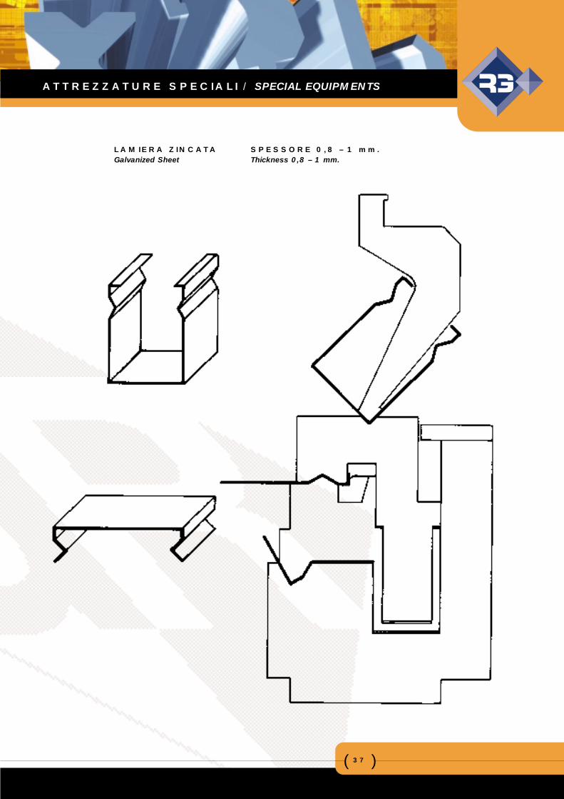
LAMIERA ZINCATA SPESSORE 0,8 – 1 mm.Galvanized Sheet Thickness 0,8 – 1 mm.
ATTREZZATURE SPECIALI / SPECIAL EQUIPMENTS
( )38
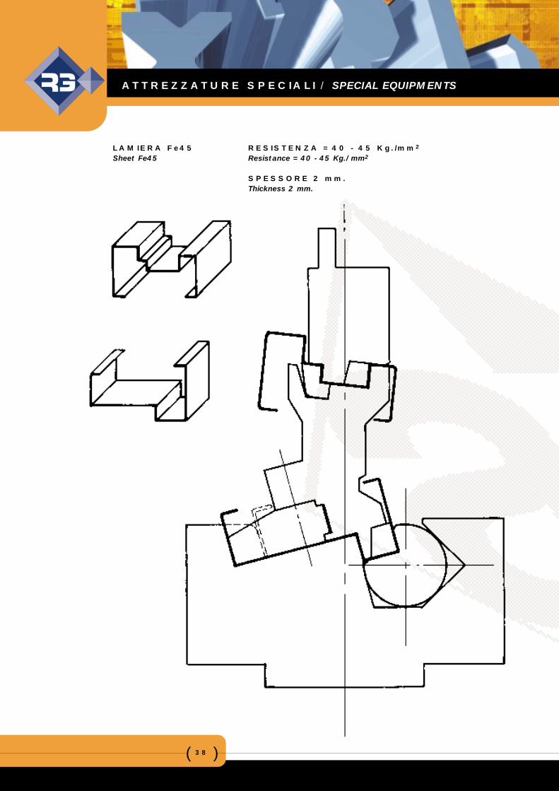
LAMIERA Fe45 RESISTENZA = 40 - 45 Kg./mm2
Sheet Fe45 Resistance = 40 - 45 Kg./mm2
SPESSORE 2 mm.Thickness 2 mm.
ATTREZZATURE SPECIALI / SPECIAL EQUIPMENTS
( )39
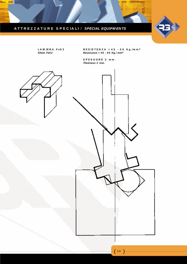
LAMIERA Fe52 RESISTENZA = 45 - 55 Kg./mm2
Sheet Fe52 Resistance = 45 - 55 Kg./mm2
SPESSORE 2 mm.Thickness 2 mm.
ATTREZZATURE SPECIALI / SPECIAL EQUIPMENTS
( )40
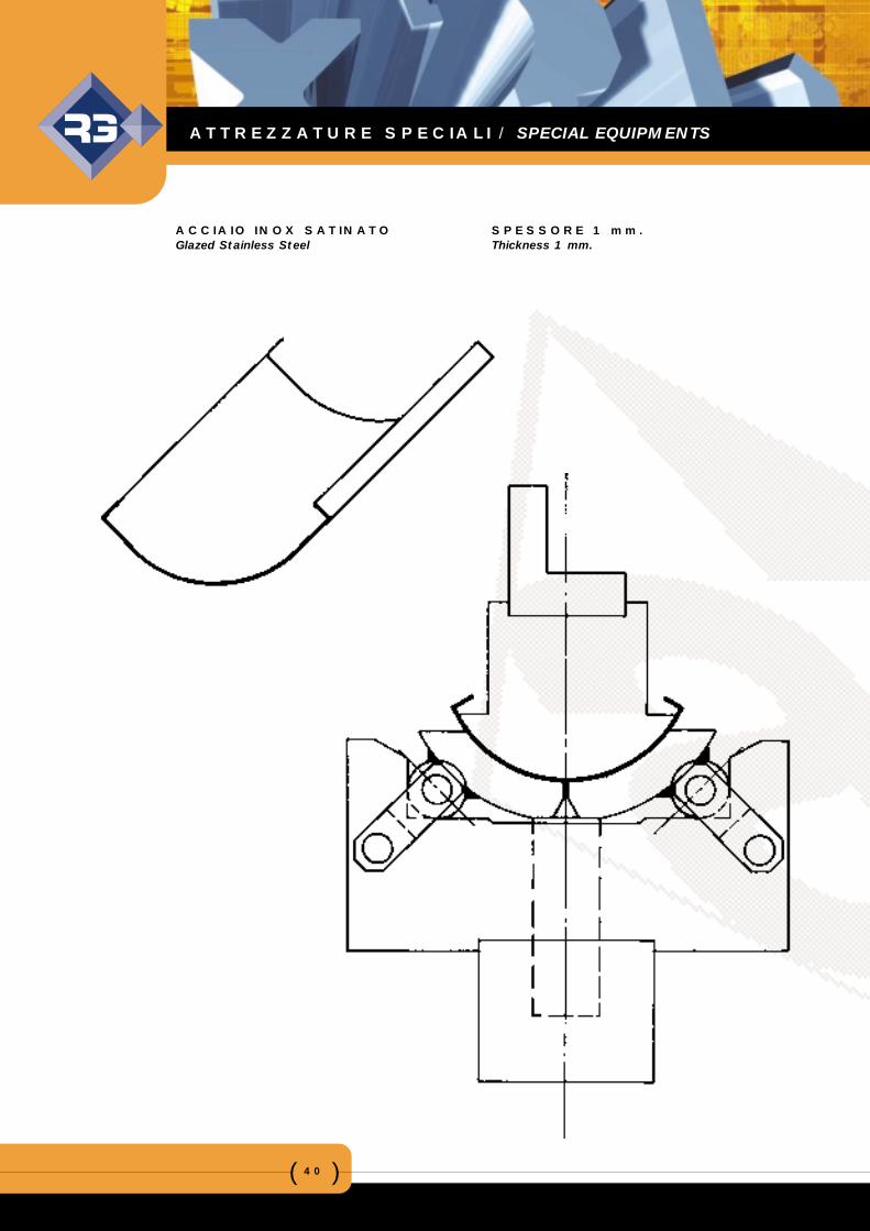
ACCIAIO INOX SATINATO SPESSORE 1 mm.Glazed Stainless Steel Thickness 1 mm.
ATTREZZATURE SPECIALI / SPECIAL EQUIPMENTS
( )41
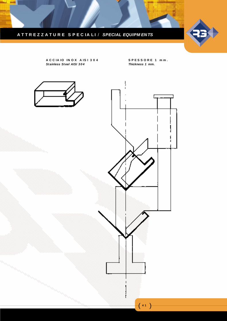
ACCIAIO INOX AISI 304 SPESSORE 1 mm.Stainless Steel AISI 304 Thickness 1 mm.
ATTREZZATURE SPECIALI / SPECIAL EQUIPMENTS
( )42
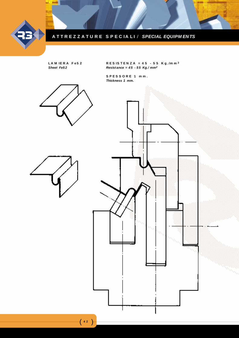
LAMIERA Fe52 RESISTENZA = 45 - 55 Kg./mm2
Sheet Fe52 Resistance = 45 - 55 Kg./mm2
SPESSORE 1 mm.Thickness 1 mm.
ATTREZZATURE SPECIALI / SPECIAL EQUIPMENTS
( )43
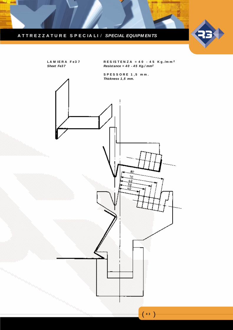
LAMIERA Fe37 RESISTENZA = 40 - 45 Kg./mm2
Sheet Fe37 Resistance = 40 - 45 Kg./mm2
SPESSORE 1,5 mm.Thickness 1,5 mm.
ATTREZZATURE SPECIALI / SPECIAL EQUIPMENTS
( )44
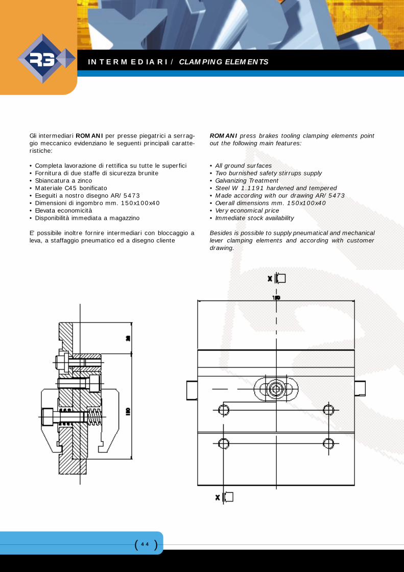
Gli intermediari ROMANI per presse piegatrici a serrag-gio meccanico evidenziano le seguenti principali caratte-ristiche:
• Completa lavorazione di rettifica su tutte le superfici• Fornitura di due staffe di sicurezza brunite• Sbiancatura a zinco• Materiale C45 bonificato• Eseguiti a nostro disegno AR/5473• Dimensioni di ingombro mm. 150x100x40• Elevata economicità• Disponibilità immediata a magazzino
E’ possibile inoltre fornire intermediari con bloccaggio aleva, a staffaggio pneumatico ed a disegno cliente
ROMANI press brakes tooling clamping elements pointout the following main features:
• All ground surfaces• Two burnished safety stirrups supply• Galvanizing Treatment• Steel W 1.1191 hardened and tempered• Made according with our drawing AR/5473• Overall dimensions mm. 150x100x40• Very economical price• Immediate stock availability
Besides is possible to supply pneumatical and mechanicallever clamping elements and according with customerdrawing.
INTERMEDIARI / CLAMPING ELEMENTS
( )45
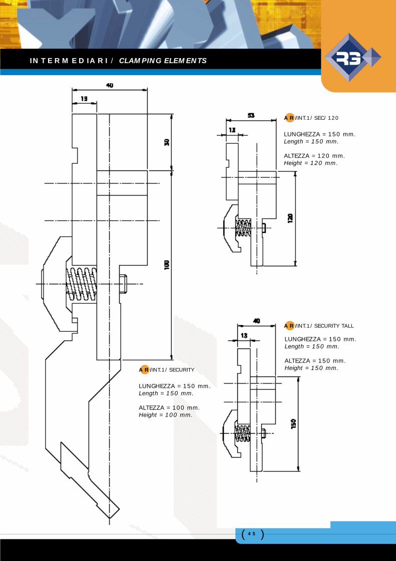
AR/INT.1/SEC/120
LUNGHEZZA = 150 mm.Length = 150 mm.
ALTEZZA = 120 mm.Height = 120 mm.
AR/INT.1/SECURITY TALL
LUNGHEZZA = 150 mm.Length = 150 mm.
ALTEZZA = 150 mm.Height = 150 mm.AR/INT.1/SECURITY
LUNGHEZZA = 150 mm.Length = 150 mm.
ALTEZZA = 100 mm.Height = 100 mm.
INTERMEDIARI / CLAMPING ELEMENTS
( )46
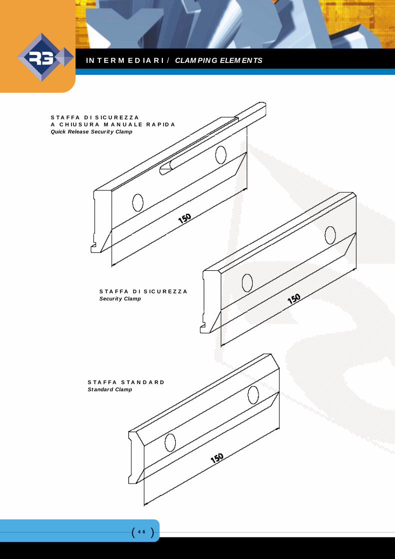
STAFFA DI SICUREZZAA CHIUSURA MANUALE RAPIDAQuick Release Security Clamp
STAFFA DI SICUREZZASecurity Clamp
STAFFA STANDARDStandard Clamp
INTERMEDIARI / CLAMPING ELEMENTS
( )47
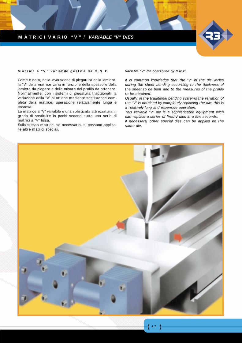
Matrice a “V” variabile gestita da C.N.C.
Come è noto, nella lavorazione di piegatura della lamiera,la “V” della matrice varia in funzione dello spessore dellalamiera da piegare e delle misure del profilo da ottenere.Normalmente, con i sistemi di piegatura tradizionali, lavariazione della “V” si ottiene mediante sostituzione com-pleta della matrice, operazione relativamente lunga ecostosa.La matrice a “V” variabile è una sofisticata attrezzatura ingrado di sostituire in pochi secondi tutta una serie dimatrici a “V” fissa.Sulla stessa matrice, se necessario, si possono applica-re altre matrici speciali.
Variable “V” die controlled by C.N.C.
It is common knowledge that the “V” of the die variesduring the sheet bending according to the thickness ofthe sheet to be bent and to the measures of the profileto be obtained.Usually, in the traditional bending systems the variation ofthe “V” is obtained by completely replacing the die: this isa relatively long and expensive operation.This variable “V” die is a sophisticated equipment wichcan replace a series of fixed-V dies in a few seconds.If necessary, other special dies can be applied on thesame die.
MATRICI VARIO “V” / VARIABLE “V” DIES
( )48
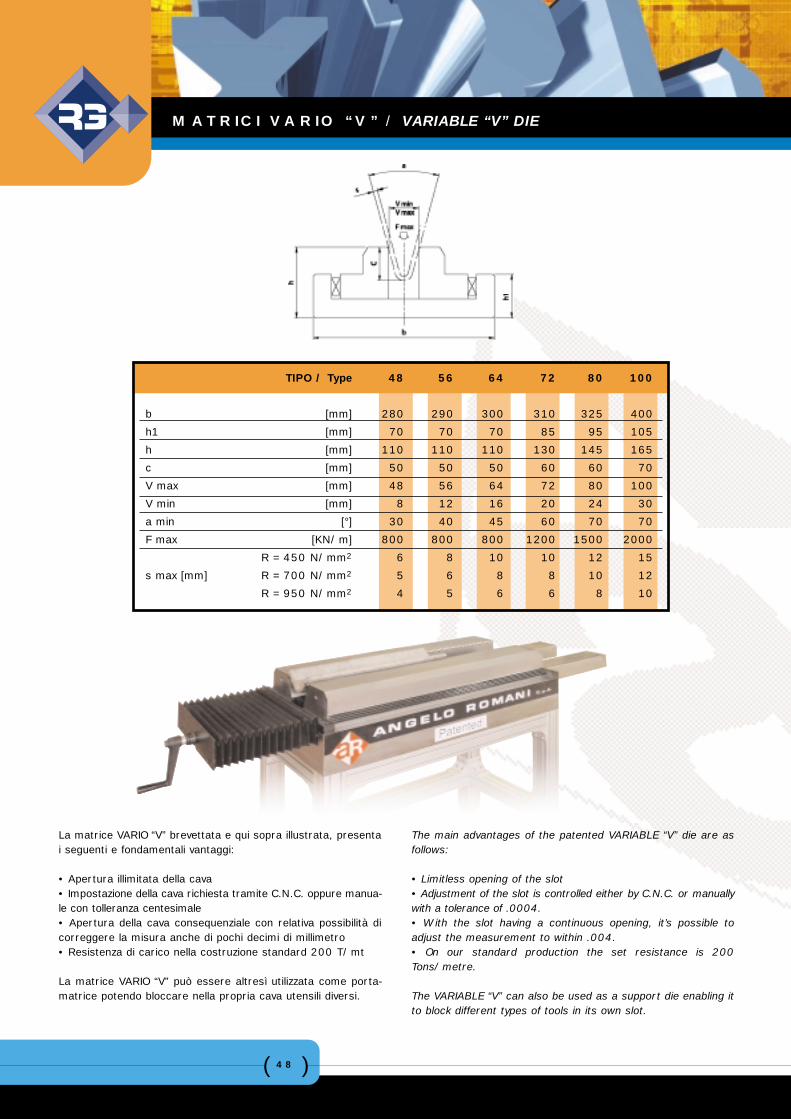
TIPO / Type 48 56 64 72 80 100
b [mm] 280 290 300 310 325 400
h1 [mm] 70 70 70 85 95 105
h [mm] 110 110 110 130 145 165
c [mm] 50 50 50 60 60 70
V max [mm] 48 56 64 72 80 100
V min [mm] 8 12 16 20 24 30
a min [°] 30 40 45 60 70 70
F max [KN/m] 800 800 800 1200 1500 2000
R = 450 N/mm2 6 8 10 10 12 15
s max [mm] R = 700 N/mm2 5 6 8 8 10 12
R = 950 N/mm2 4 5 6 6 8 10
MATRICI VARIO “V” / VARIABLE “V” DIE
La matrice VARIO “V” brevettata e qui sopra illustrata, presentai seguenti e fondamentali vantaggi:
• Apertura illimitata della cava• Impostazione della cava richiesta tramite C.N.C. oppure manua-le con tolleranza centesimale• Apertura della cava consequenziale con relativa possibilità dicorreggere la misura anche di pochi decimi di millimetro• Resistenza di carico nella costruzione standard 200 T/mt
La matrice VARIO “V” può essere altresì utilizzata come porta-matrice potendo bloccare nella propria cava utensili diversi.
The main advantages of the patented VARIABLE “V” die are asfollows:
• Limitless opening of the slot• Adjustment of the slot is controlled either by C.N.C. or manuallywith a tolerance of .0004.• With the slot having a continuous opening, it’s possible toadjust the measurement to within .004.• On our standard production the set resistance is 200Tons/metre.
The VARIABLE “V” can also be used as a support die enabling itto block different types of tools in its own slot.
( )49
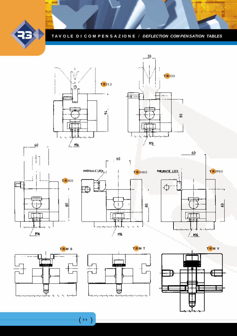
CaratteristicheLe attuali esigenze nella piegatura della lamiera richiedono unasempre maggior precisione dei profili piegati e quindi angoli dipiega costanti.L’uniformità dell’angolo di piega dipende da diversi fattori tra cuirisulta importantissima la costanza di penetrazione del punzonenella matrice per tutta la sua lunghezza.Durante la piegatura, sotto carico, la tavola superiore e la tavo-la inferiore della pressa piegatrice subiscono una leggera fles-sione determinando angoli di piega irregolari. Per ovviare a que-sto inconveniente, la Società ROMANI ha messo a punto unaparticolare tavola di compensazione.
FunzionamentoIl principio di funzionamento consiste nel centinare adeguata-mente la tavola di compensazione facendo slittare simultanea-mente ed in pochi secondi una serie di cunei e controcunei aconicità differenziata, calcolati secondo le caratteristiche dellapressa piegatrice e disposti al suo interno in senso longitudina-le. La centina che si ottiene è destinata a compensare la fles-sione della pressa stessa.
RegolazioneLa regolazione dei cunei può avvenire in due modi diversi:• manualmente tramite un volantino• automaticamente mediante un motoriduttore gestito da C.N.C.
ConclusioniLe tavole di compensazione ROMANI vengono costruite surichiesta in base al tipo di pressa piegatrice ed in funzione dellematrici che si utilizzano.L’ufficio tecnico è a disposizione per fornire ulteriori informazionie dettagli tecnico-commerciali per la soluzione di qualsiasi pro-blema di piegatura.
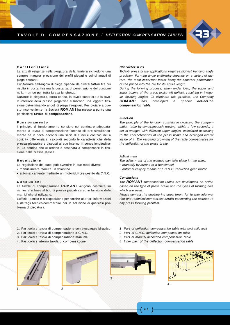
1. Particolare tavola di compensazione con bloccaggio idraulico2. Particolare tavola di compensazione a C.N.C.3. Particolare tavola di compensazione manuale4. Particolare interno tavola di compensazione
CharacteristicsToday’s press brake applications requires highest bending angleprecision. Forming angle uniformity depends on a variety of fac-tors; the most important factor being the constant penetrationof the punch into the die for its entire length.During the forming process, when under load, the upper andlower beams of the press brake will deflect, resulting in irregu-lar forming angles. To eliminate this problem, the CompanyROMANI has developed a special deflectioncompensation table.
FunctionThe principle of the function consists in crowning the compen-sation table by simultaneously moving, within a few seconds, aset of wedges with different taper angles, calculated accordingto the characteristics of the press brake and arranged lateralinside of it. The resulting crowning of the table compensates forthe deflection of the press brake.
AdjustmentThe adjustment of the wedges can take place in two ways:• manually by means of a handwheel• automatically by means of a C.N.C. reduction gear motor
ConclusionsThe ROMANI compensation tables are developped on order,based on the type of press brake and the types of forming dieswhich are used.Please contact the engineering department for further informa-tion and technical-commercial details concerning the solution toany press forming problem.
1. Part of deflection compensation table with hydraulic lock2. Part of C.N.C. deflection compensation table3. Part of manual deflection compensation table4. Inner part of the deflection compensation table
1. 2.
3.
4.
TAVOLE DI COMPENSAZIONE / DEFLECTION COMPENSATION TABLES
( )50
TAVOLE DI COMPENSAZIONE / DEFLECTION COMPENSATION TABLES
TR/13
TR/30
TR/60
TR/H60 TR/P60
TRMS TRMT TRMV
( )51
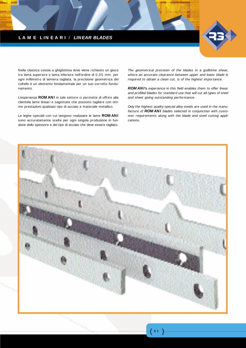
Nella classica cesoia a ghigliottina dove viene richiesto un giocotra lama superiore e lama inferiore nell’ordine di 0,05 mm. perogni millimetro di lamiera tagliata, la precisione geometrica delcoltello è un elemento fondamentale per un suo corretto funzio-namento.
L’esperienza ROMANI in tale settore ci permette di offrire allaclientela lame lineari e sagomate che possono tagliare con otti-me prestazioni qualsiasi tipo di acciaio e materiale metallico.
Le leghe speciali con cui vengono realizzate le lame ROMANIsono accuratamente scelte per ogni singola produzione in fun-zione dello spessore e del tipo di acciaio che deve essere tagliato.
The geometrical precision of the blades in a guillotine shear,where an accurate clearance between upper and lower blade isrequired to obtain a clean cut, is of the highest importance.
ROMANI’s experience in this field enables them to offer linearand profiled blades for standard use that will cut all types of steeland sheet giving outstanding performance.
Only the highest quality special alloy steels are used in the manu-facture of ROMANI blades selected in conjunction with custo-mer requirements along with the blade and steel cutting appli-cations.
LAME LINEARI / LINEAR BLADES
( )52
LAME LINEARI / LINEAR BLADES
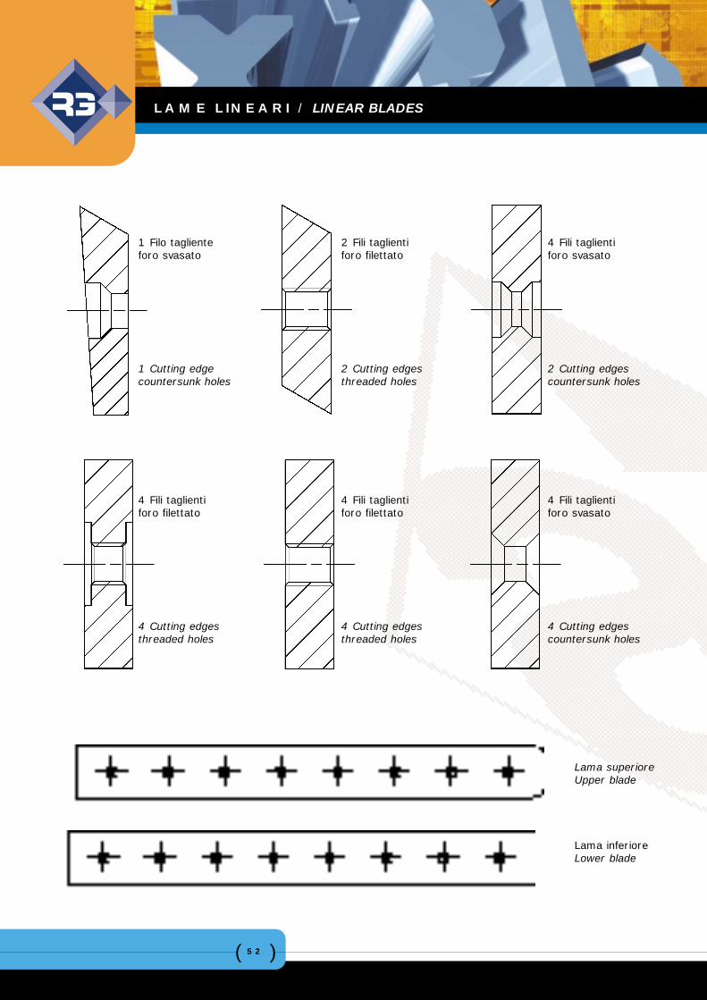
1 Filo taglienteforo svasato
1 Cutting edgecountersunk holes
2 Fili taglientiforo filettato
2 Cutting edgesthreaded holes
4 Fili taglientiforo svasato
2 Cutting edgescountersunk holes
4 Fili taglientiforo filettato
4 Cutting edgesthreaded holes
4 Fili taglientiforo filettato
4 Cutting edgesthreaded holes
4 Fili taglientiforo svasato
4 Cutting edgescountersunk holes
Lama inferioreLower blade
Lama superioreUpper blade
( )53
CERTIFICAZIONE / CERTIFICATION
( )54
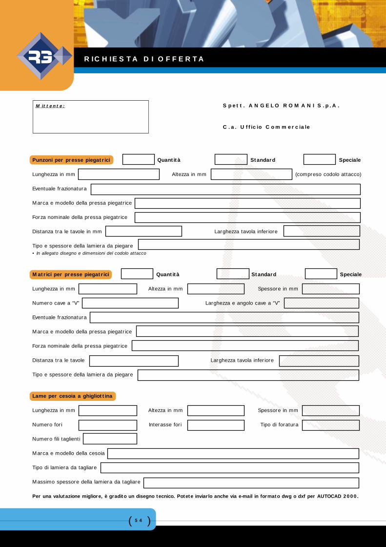
RICHIESTA DI OFFERTA
Punzoni per presse piegatrici Quantità Standard Speciale
Lunghezza in mm Altezza in mm (compreso codolo attacco)
Eventuale frazionatura
Marca e modello della pressa piegatrice
Forza nominale della pressa piegatrice
Distanza tra le tavole in mm Larghezza tavola inferiore
Tipo e spessore della lamiera da piegare• In allegato disegno e dimensioni del codolo attacco
Matrici per presse piegatrici Quantità Standard Speciale
Lunghezza in mm Altezza in mm Spessore in mm
Numero cave a “V” Larghezza e angolo cave a “V”
Eventuale frazionatura
Marca e modello della pressa piegatrice
Forza nominale della pressa piegatrice
Distanza tra le tavole Larghezza tavola inferiore
Tipo e spessore della lamiera da piegare
Lame per cesoia a ghigliottina
Lunghezza in mm Altezza in mm Spessore in mm
Numero fori Interasse fori Tipo di foratura
Numero fili taglienti
Marca e modello della cesoia
Tipo di lamiera da tagliare
Massimo spessore della lamiera da tagliare
Per una valutazione migliore, è gradito un disegno tecnico. Potete inviarlo anche via e-mail in formato dwg o dxf per AUTOCAD 2000.
Mittente: Spett. ANGELO ROMANI S.p.A.
C.a. Ufficio Commerciale
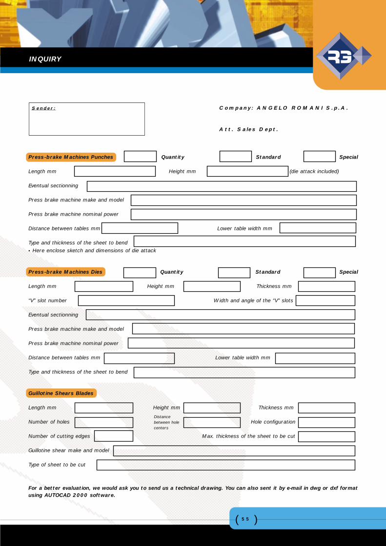
Press-brake Machines Punches Quantity Standard Special
Length mm Height mm (die attack included)
Eventual sectionning
Press brake machine make and model
Press brake machine nominal power
Distance between tables mm Lower table width mm
Type and thickness of the sheet to bend• Here enclose sketch and dimensions of die attack
Press-brake Machines Dies Quantity Standard Special
Length mm Height mm Thickness mm
“V” slot number Width and angle of the “V” slots
Eventual sectionning
Press brake machine make and model
Press brake machine nominal power
Distance between tables mm Lower table width mm
Type and thickness of the sheet to bend
Guillotine Shears Blades
Length mm Height mm Thickness mm
Number of holes Hole configuration
Number of cutting edges Max. thickness of the sheet to be cut
Guillotine shear make and model
Type of sheet to be cut
For a better evaluation, we would ask you to send us a technical drawing. You can also sent it by e-mail in dwg or dxf formatusing AUTOCAD 2000 software.
Sender: Company: ANGELO ROMANI S.p.A.
Att. Sales Dept.
Distance between holecenters
INQUIRY
( )55
ANGELO ROMANI S.p.A.
Via Sempione, 24920016 Pero - fraz. Cerchiate - Milano - ITALY
Tel. ++39 02 33 94 131 Fax ++39 02 35 80 850www.romani.it - [email protected]
AD
_Deb
ora
Del
Neg
roCat
alog
o La
vora
zion
e La
mie
ra 0
5 2
002