
RGC (ООО «РОССИ») – авторизованный Serie AS AS series Тел.
62
Motoriduttori a vite STANDARDFIT STANDARDFIT Worm gearmotors Serie AS AS series RGC (ООО «РОССИ») – авторизованный представитель компании Rossi на территории Российской Федерации и стран Таможенного Союза Тел.: +7 910 122-91-25 www.rgc-group.ru
Transcript of RGC (ООО «РОССИ») – авторизованный Serie AS AS series Тел.

Motoriduttori a vite STANDARDFITSTANDARDFIT Worm gearmotors
Serie ASAS series
RGC (ООО «РОССИ») – авторизованный представитель компании Rossi
на территории Российской Федерации и стран Таможенного Союза
Тел.: +7 910 122-91-25www.rgc-group.ru


1AS Series 2620-01.01

2 2620-01.01AS Series
32620-01.01 AS Series
Indice Contents1
2
3
4
56
Rossi for You Rossi for You
Caratteristiche, vantaggi e gamma
4
8
20
48
52
58
Panoramica del prodotto
Formule tecniche
Accessori ed esecuzioni speciali
Features, benefits and range
Product Overview
Installazione e manutenzione
Accessories and non-standard designs
Technical formulae
Installation and maintenance

InnovazioneRossi offre un’ampia gamma di soluzioni per un mondo industriale in continua evoluzione, riduttori e motoriduttori flessibili e innovativi anche per applicazioni customizzate, volte a massimizzare le prestazioni e minimizzare il costo totale di proprietà (TCO).
Alta qualità, 3 anni di garanziaIl nostro obiettivo è innovare e migliorare la produttività con prodotti performanti, precisi, affidabili e di alta qualità, in tutto il mondo. Siamo sempre un passo avanti nell’offrire e sviluppare soluzioni in grado di soddisfare infinite esigenze applicative, anche nelle condizioni più severe.
AffidabilitàSiamo un’azienda affidabile, in grado di offrire flessibilità e know-how per rispondere alle diverse esigenze di mercato a livello internazionale, in tutti i settori industriali, attenta alla sostenibilità ambientale e ai valori etici e di sicurezza, per la salvaguardia del futuro.
Strumenti e processiContinuiamo a investire in nuovi strumenti e processi, il nostro team di specialisti altamente specializzati in diversi settori è in grado di individuare la soluzione più adatta alle vostre esigenze. Siamo sempre al vostro fianco in ogni fase del progetto.
Servizio post venditaI nostri tecnici altamente qualificati assicurano un servizio post-vendita veloce ed efficiente in tutto il mondo.
Supporto digitaleOltre al nostro portale Rossi for You disponibile 24/7, una suite di strumenti digitali consente di accedere in tempo reale al tracking degli ordini, alle fatture, al download dei disegni dei ricambi e contattare il nostro servizio di assistenza.
EsperienzaPlasmata da oltre 60 anni di storia, Rossi è in grado di soddisfare qualsiasi vostra esigenza, sia che si tratti di un progetto standard o di una soluzione personalizzata.
Rossi for You1
4 2620-01.01AS Series

InnovationRossi off ers a wide range of solutions for an evolving industry, fl exible and innovative gearboxes and gearmotors for customer tailored solutions to maximize performance and minimize the total cost of ownership.
High quality, 3 years warrantyOur drive is to innovate and boost operations by manufacturing performing, precise, reliable and high-quality products all over the world. We are always one step forward in off ering and developing solutions that can
satisfy an unlimited number of application needs, even in the most demanding conditions.
ReliabilityWe are a reliable company with the right fl exibility and know-how to respond to worldwide market requests, in all application fi elds, without leaving aside our commitment for the environment and value on human safety, to protect everyone’s future.
Tools and processesWe continue to invest in new tools and processes, so our highly skilled specialist team in diff erent fi elds are supporting you to fi nd the best solution suitable for your demands, always by your side on every step of the project.
After-sale serviceHighly trained mechanics and support teams can ensure a fast and effi cient after-sale service providing support worldwide.
Digital supportAlongside our 24/7 Rossi for You support portal you have a suite of digital support tools enabling real time access to your order tracking, invoices, spare part tables download and contact to our service.
ExperienceShaped by more than 60 years of history Rossi meets your unique needs whether you need a standard design or a customized solution.
5AS Series 2620-01.01

6 2620-01.01AS Series
Global presencelocal service
A widespread sales network of subsidiaries and dealers in nearly all industrialized countries. By your side from the design to after-sale phase, Rossi is a fl exible and dependable partner throughout the world.
Rossi for You, our customer web portal, provides a 24/7 global coordination of the ordering, supply and service processes.
United StatesSuwanee, GA
*Tutti i contatti sono indicati in www.rossi.com.*All contacts available on www.rossi.com
BrazilCordeiropolis, SP
Local supportSales, customer service,technical support, spare parts
15 branches*
Worldwide distribution network*
Presenza globale,servizio locale
Una rete capillare di fi liali e distributori a livello internazionale. Dalla fase di progettazione al servizio post-vendita Rossi è sempre al vostro fi anco, un partner locale affi dabile e fl essibile.
Rossi for You, la suite digitale disponibile 24/7 per la consultazione continua e aggiornata di ordini, spedizioni e assistenza.
Assistenza localeVendita, customer service,supporto tecnico, ricambi
15 fi liali*
Rete di distribuzione internazionale*

72620-01.01 AS Series
Sede Headquarters
Filiali Branches
Stabilimenti di produzione/Centri di montaggio Production facilities/Assembly plants
AustraliaPerth
ChinaShanghai
Souzhou
IndiaCoimbatore
MalaysiaKuala Lumpur
TaiwanKaohsiung City
GermanyDreieich
United KingdomCoventry
South AfricaLa Mercy
SpainBarcelona
FranceSaint Priest
ItalyModena
Ganaceto
Lecce
TurkeyIzmir
PolandWroclaw
NetherlandsPanningen
Caratteristiche, vantaggi e gamma
2
8 2620-01.01AS Series
Caratteristiche, vantaggi e gamma
2

Features,benefi ts and range
ModularitàModular system
SostenibilitàSustainability
Massime prestazioniMaximum performance
InnovazioneInnovation
DigitalizzazioneDigitalization
Know-howEsperienza
CustomizationCustomizzazione
Soluzioni di alta qualità ed effi cienti in termini di costiFor cost–eff ective
and high quality solutions
Rispettiamo l'ambienteWe care
about environment
Le applicazioni più complesse sono movimentatedai prodotti Rossi
We drive the heaviest applications worldwide
Siamo orientati al futuro per un'industria in costante evoluzioneWe are constantly thinking forward, solutions for an evolving industry
Rossi for You è sempre a disposizione per qualsiasi informazione
Rossi for You is always at your disposal for any info
La nostra esperienza al vostro servizio
We support you through interdisciplinary know-how
Prodotto standard adattabile ad applicazioni su misura
Cost-eff ective solutions starting from standard products
9AS Series 2620-01.01
Massime prestazioniMaximum performance
un'industria in costante evoluzioneWe are constantly thinking forward, solutions for an evolving industry
10 2620-01.01AS Series
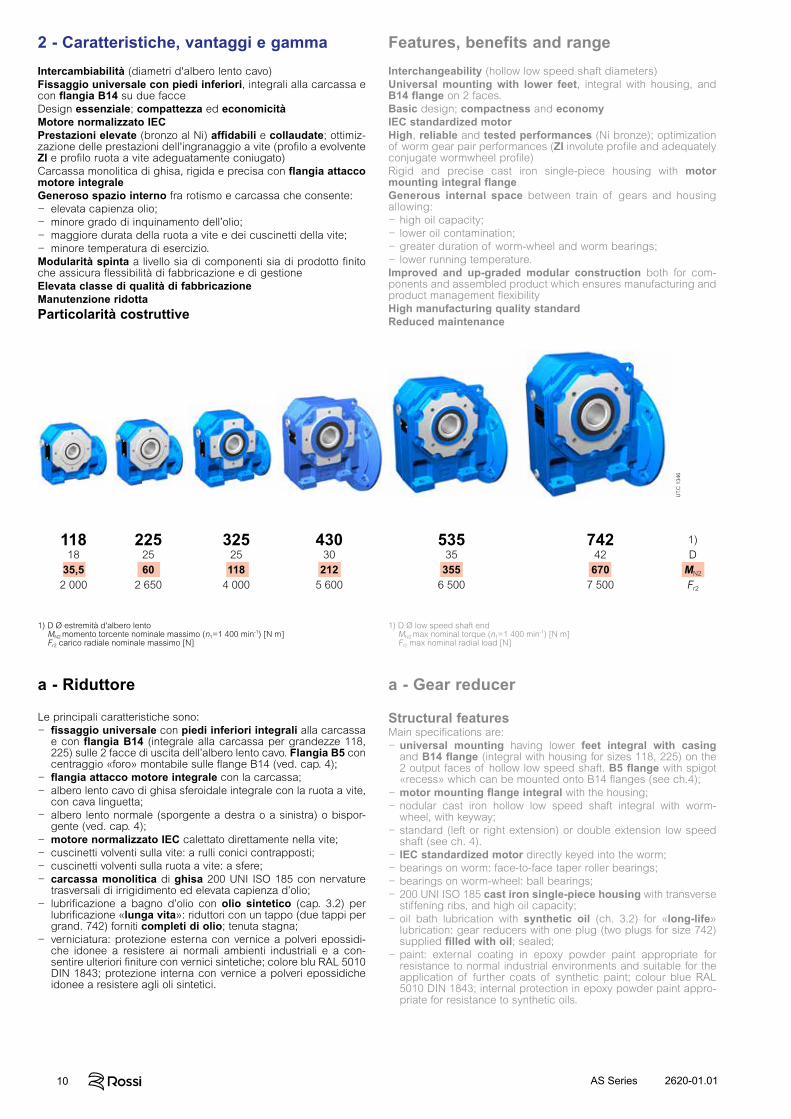
Intercambiabilità (diametri d'albero lento cavo)Fissaggio universale con piedi inferiori, integrali alla carcassa e con flangia B14 su due facceDesign essenziale; compattezza ed economicitàMotore normalizzato IECPrestazioni elevate (bronzo al Ni) affidabili e collaudate; ottimiz-zazione delle prestazioni dell'ingranaggio a vite (profilo a evolvente ZI e profilo ruota a vite adeguatamente coniugato)Carcassa monolitica di ghisa, rigida e precisa con flangia attacco motore integraleGeneroso spazio interno fra rotismo e carcassa che consente:− elevata capienza olio;− minore grado di inquinamento dell’olio;− maggiore durata della ruota a vite e dei cuscinetti della vite;− minore temperatura di esercizio.Modularità spinta a livello sia di componenti sia di prodotto finito che assicura flessibilità di fabbricazione e di gestioneElevata classe di qualità di fabbricazioneManutenzione ridottaParticolarità costruttive
Interchangeability (hollow low speed shaft diameters)Universal mounting with lower feet, integral with housing, and B14 flange on 2 faces. Basic design; compactness and economyIEC standardized motorHigh, reliable and tested performances (Ni bronze); optimization of worm gear pair performances (ZI involute profile and adequately conjugate wormwheel profile)Rigid and precise cast iron single-piece housing with motor mounting integral flangeGenerous internal space between train of gears and housing allowing:− high oil capacity;− lower oil contamination;− greater duration of worm-wheel and worm bearings;− lower running temperature.Improved and up-graded modular construction both for com-ponents and assembled product which ensures manufacturing and product management flexibilityHigh manufacturing quality standardReduced maintenance
a - Riduttore a - Gear reducer
1) D Ø estremità d'albero lentoMN2 momento torcente nominale massimo (n1=1 400 min-1) [N m]Fr2 carico radiale nominale massimo [N]
1) D Ø low speed shaft endMN2 max nominal torque (n1=1 400 min-1) [N m]Fr2 max nominal radial load [N]
Le principali caratteristiche sono:− fissaggio universale con piedi inferiori integrali alla carcassa
e con flangia B14 (integrale alla carcassa per grandezze 118, 225) sulle 2 facce di uscita dell’albero lento cavo. Flangia B5 con centraggio «foro» montabile sulle flange B14 (ved. cap. 4);
− flangia attacco motore integrale con la carcassa;− albero lento cavo di ghisa sferoidale integrale con la ruota a vite,
con cava linguetta;− albero lento normale (sporgente a destra o a sinistra) o bispor-
gente (ved. cap. 4);− motore normalizzato IEC calettato direttamente nella vite;− cuscinetti volventi sulla vite: a rulli conici contrapposti;− cuscinetti volventi sulla ruota a vite: a sfere;− carcassa monolitica di ghisa 200 UNI ISO 185 con nervature
trasversali di irrigidimento ed elevata capienza d’olio;− lubrificazione a bagno d’olio con olio sintetico (cap. 3.2) per
lubrificazione «lunga vita»: riduttori con un tappo (due tappi per grand. 742) forniti completi di olio; tenuta stagna;
− verniciatura: protezione esterna con vernice a polveri epossidi-che idonee a resistere ai normali ambienti industriali e a con-sentire ulteriori finiture con vernici sintetiche; colore blu RAL 5010 DIN 1843; protezione interna con vernice a polveri epossidiche idonee a resistere agli oli sintetici.
Structural featuresMain specifications are:− universal mounting having lower feet integral with casing
and B14 flange (integral with housing for sizes 118, 225) on the 2 output faces of hollow low speed shaft. B5 flange with spigot «recess» which can be mounted onto B14 flanges (see ch.4);
− motor mounting flange integral with the housing;− nodular cast iron hollow low speed shaft integral with worm-
wheel, with keyway;− standard (left or right extension) or double extension low speed
shaft (see ch. 4).− IEC standardized motor directly keyed into the worm;− bearings on worm: face-to-face taper roller bearings;− bearings on worm-wheel: ball bearings;− 200 UNI ISO 185 cast iron single-piece housing with transverse
stiffening ribs, and high oil capacity;− oil bath lubrication with synthetic oil (ch. 3.2) for «long-life»
lubrication: gear reducers with one plug (two plugs for size 742) supplied filled with oil; sealed;
− paint: external coating in epoxy powder paint appropriate for resistance to normal industrial environments and suitable for the application of further coats of synthetic paint; colour blue RAL 5010 DIN 1843; internal protection in epoxy powder paint appro-priate for resistance to synthetic oils.
11818
35,52 000
74242
6707 500
2252560
2 650
32525118
4 000
43030
2125 600
53535
3556 500
1)D
MN2
Fr2
UT.
C 1
346
2 - Caratteristiche, vantaggi e gamma Features, benefits and range
112620-01.01 AS Series
Train of gears:− worm gear pair;− 6 sizes with final reduction centre distance to R 10 series;− nominal transmission ratios to R 10 series (6 … 75);− casehardened/hardened cylindrical worm made of 16MnCr5 EN
10084-98 steel with ground and superfinished involute profile (ZI);− worm-wheel with profile especially conjugate to the worm through
hob optimization, with hub in nodular cast iron and Ni bronze CuSn12Ni2-B (EN1982-98) gear rim with high pureness and con-trolled phosphor contents;
− train of gear load capacity calculated for breakage and wear; thermal capacity verified.
Specific standards:− nominal transmission ratios and principal dimensions according
to UNI 2016 standard numbers (DIN 323-74, NF X 01.001, BS 2045-65, ISO 3-73);
− basic rack to BS 721-83; involute profile (ZI) to UNI 4760/4-77 (DIN 3975-76), ISO/R 1122/2-69);
− shaft heights to UNI 2946-68 (DIN 747-67, NF E 01.051, BS 5186- 75, ISO 496-73);
− fixing flanges B14 and B5 (the latter with spigot «recess») taken from UNEL 13501-69 (DIN 42948-65, IEC 72.2);
− medium series fixing holes to UNI 1728-83 (DIN 69-71, NF E 27.040, BS 4186-67, ISO/R 273);
− cylindrical shaft ends (short, size 118 excluded) to UNI ISO 775-88 (DIN 748, NF E 22.051, BS 4506-70, ISO/R775/88) with tapped butt-end hole to UNI 9321 (DIN 332 BI. 2-70, NF E 22.056) exclud-ing d-D diameter ratio;
− parallel keys to UNI 6604-69 (DIN 6885 Bl. 1-68, NF E 27.656 and 22.175, BS 4235.1-72, ISO/R 773-69) except for specific cases of motor-to-gear reducer coupling where key height is reduced;
− mounting positions taken from UNEL 05513-67 (DIN 42950-64, IEC 34;7);
− worm gear pair load capacity and efficiency to BS 721-83 inte-grated with ISO/CD 14521.
Sound levelsThe standard levels of sound power emission LWA relevant to the gearmotors of this catalogue, running at nominal load and speed, fulfil the limits settled by VDI 2159 for gear reducers and EN 60034 for motors.
Rotismo:− a vite;− 6 grandezze con interasse riduzione finale secondo serie R 10;− rapporti di trasmissione nominali secondo serie R 10 (6 ... 75);− vite cilindrica di acciaio 16MnCr5 EN 10084-98 cementata/tem-
prata con profilo a evolvente (ZI) rettificato e superfinito;− ruota a vite con profilo adeguatamente coniugato a quello della
vite tramite ottimizzazione del creatore, con mozzo di ghisa sfe-roidale e corona di bronzo al Ni CuSn12Ni2-B (EN1982-98) con elevata purezza e tenore di fosforo controllato;
− capacità di carico del rotismo calcolata a rottura e ad usura; veri-fica capacità termica.
Norme specifiche:− rapporti di trasmissione nominali e dimensioni principali secondo
numeri normali UNI 2016 (DIN 323-74, NF X 01.001, BS 2045-65, ISO 3-73);
− dentiera di riferimento secondo BS 721-83; profilo ad evolvente (ZI) secondo UNI 4760/4-77 (DIN 3975-76, ISO/R 1122/2-69);
− altezze d’asse secondo UNI 2946-68 (DIN 747-67, NF E 01.051, BS 5186-75, ISO 496-73);
− flange di fissaggio B14 e B5 (quest’ultima con centraggio «foro») derivate da UNEL 13501-69 (DIN 42948-65, IEC 72.2);
− fori di fissaggio serie media secondo UNI 1728-83 (DIN 69-71, NF E 27.040, BS 4186-67, ISO/R 273);
− estremità d’albero cilindriche (corte, esclusa grand. 118) secon-do UNI ISO 775-88 (DIN 748, NF E 22.051, BS 4506-70, ISO/R775-88) con foro filettato in testa secondo UNI 9321 (DIN 332 BI. 2-70, NF E 22.056) escluso corrispondenza d-D;
− linguette UNI 6604-69 (DIN 6885 Bl. 1-68, NF E 27.656 e 22.175, BS 4235.1-72, ISO/R 773-69) eccetto per determinati casi di accoppiamento motore/riduttore in cui sono ribassate;
− forme costruttive derivate da UNEL 05513-67 (DIN 42950-64, IEC 34.7);
− capacità di carico e rendimento dell’ingranaggio a vite determi-nati in base a BS 721-83 integrata con ISO/CD 14521.
Livelli sonoriI livelli normali di emissione di potenza sonora LWA per i motoriduttori del presente catalogo, in servizio a carico e velocità nominali, sono conformi ai limiti previsti da VDI 2159 per la parte riduttore e da EN 60034 per la parte motore.
2 - Caratteristiche, vantaggi e gamma Features, benefits and range
12 2620-01.01AS Series
2 - Caratteristiche, vantaggi e gamma Features, benefits and range
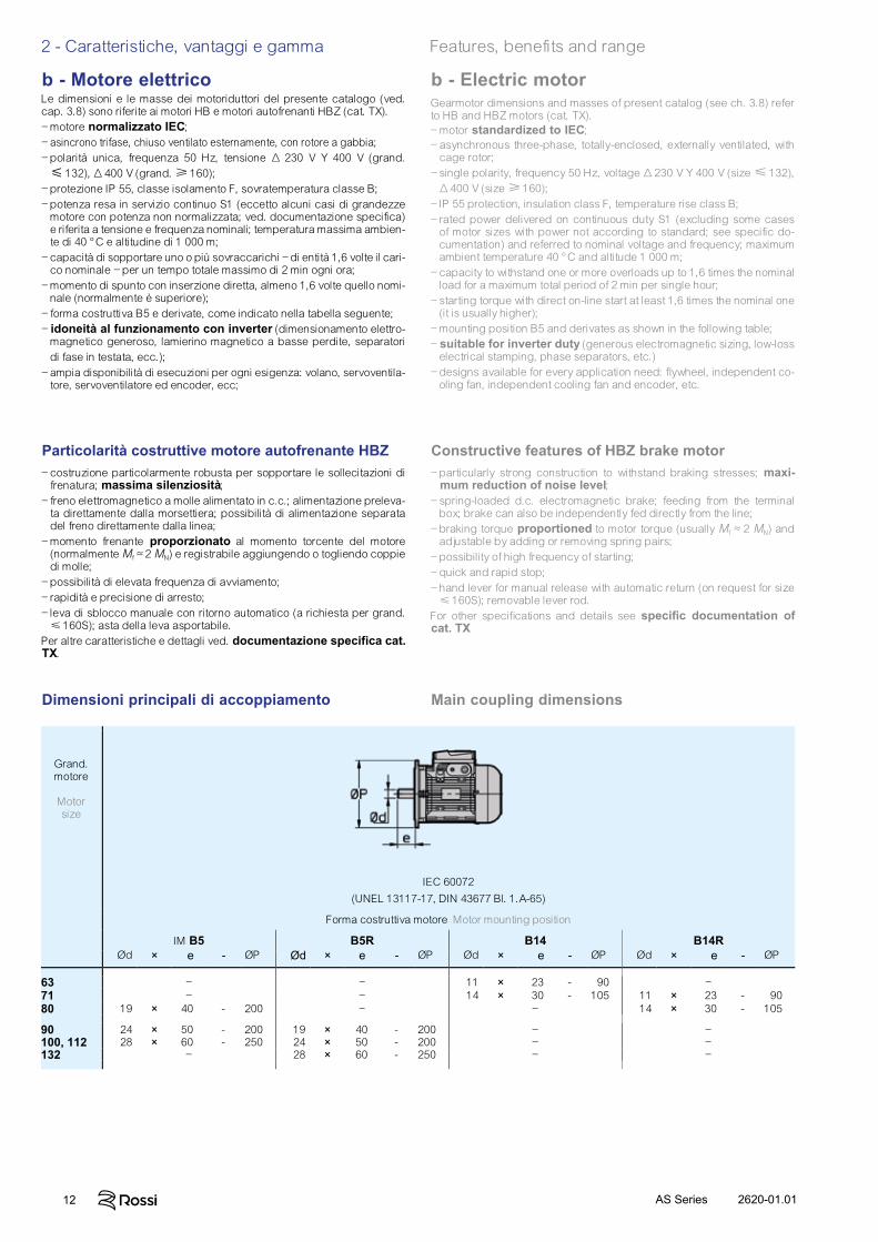
Grand.motore
Motorsize
IEC 60072
(UNEL 13117-17, DIN 43677 Bl. 1.A-65)
Forma costruttiva motore Motor mounting position
IM B5 B5R B14 B14RØd × e - ØP Ød × e - ØP Ød × e - ØP Ød × e - ØP
63 – – 11 × 23 - 190 –71 – – 14 × 30 - 105 11 × 23 - 19080 19 × 40 - 200 – – 14 × 30 - 105
90 24 × 50 - 200 19 × 40 - 200 – –100, 112 28 × 60 - 250 24 × 50 - 200 – –132 – 28 × 60 - 250 – –
Main coupling dimensions Dimensioni principali di accoppiamento
Particolarità costruttive motore autofrenante HBZ– costruzione particolarmente robusta per sopportare le sollecitazioni di
frenatura; massima silenziosità;– freno elettromagnetico a molle alimentato in c.c.; alimentazione preleva-
ta direttamente dalla morsettiera; possibilità di alimentazione separata del freno direttamente dalla linea;
– momento frenante proporzionato al momento torcente del mo tore (normalmente Mf ≈ 2 MN) e registrabile aggiungendo o to gliendo coppie di molle;
– possibilità di elevata frequenza di avviamento;– rapidità e precisione di arresto;– leva di sblocco manuale con ritorno automatico (a richiesta per grand.
160S); asta della leva asportabile.Per altre caratteristiche e dettagli ved. documentazione specifica cat. TX.
Constructive features of HBZ brake motor– particularly strong construction to withstand braking stresses; maxi-
mum reduction of noise level;– spring-loaded d.c. electromagnetic brake; feeding from the terminal
box; brake can also be independently fed directly from the line;– braking torque proportioned to motor torque (usually Mf ≈ 2 MN) and
adjustable by adding or removing spring pairs;– possibility of high frequency of starting;– quick and rapid stop;– hand lever for manual release with automatic return (on request for size
160S); removable lever rod.For other specifi cations and details see specifi c documentation of cat. TX
b - Motore elettricoLe dimensioni e le masse dei motoriduttori del presente catalogo (ved. cap. 3.8) sono riferite ai motori HB e motori autofrenanti HBZ (cat. TX).– motore normalizzato IEC;– asincrono trifase, chiuso ventilato esternamente, con rotore a gabbia;– polarità unica, frequenza 50 Hz, tensione Δ 230 V Y 400 V (grand. 132), Δ 400 V (grand. 160);
– protezione IP 55, classe isolamento F, sovratemperatura classe B;– potenza resa in servizio continuo S1 (eccetto alcuni casi di grandezze
motore con potenza non normalizzata; ved. documentazione specifica) e riferita a tensione e frequenza nominali; temperatura massima ambien-te di 40 °C e altitudine di 1 000 m;
– capacità di sopportare uno o più sovraccarichi – di entità 1,6 volte il cari-co nominale – per un tempo totale massimo di 2 min ogni ora;
– momento di spunto con inserzione diretta, almeno 1,6 volte quello nomi-nale (normalmente è superiore);
– forma costruttiva B5 e derivate, come indicato nella tabella se guente;– idoneità al funzionamento con inverter (dimensionamento elettro-
magnetico generoso, lamierino magnetico a basse perdite, separatori di fase in testata, ecc.);
– ampia disponibilità di esecuzioni per ogni esigenza: volano, servoventila-tore, servoventilatore ed encoder, ecc;
b - Electric motorGearmotor dimensions and masses of present catalog (see ch. 3.8) refer to HB and HBZ motors (cat. TX).– motor standardized to IEC;– asynchronous three-phase, totally-enclosed, externally ventilated, with
cage rotor;– single polarity, frequency 50 Hz, voltage Δ 230 V Y 400 V (size 132),
Δ 400 V (size 160);– IP 55 protection, insulation class F, temperature rise class B;– rated power delivered on continuous duty S1 (excluding some cases
of motor sizes with power not according to standard; see specific do-cumentation) and referred to nominal voltage and frequency; maximum ambient temperature 40 °C and altitude 1 000 m;
– capacity to withstand one or more overloads up to 1,6 times the nominal load for a maximum total period of 2 min per single hour;
– starting torque with direct on-line start at least 1,6 times the nominal one (it is usually higher);
– mounting position B5 and derivates as shown in the following table;– suitable for inverter duty (generous electromagnetic sizing, low-loss
electrical stamping, phase separators, etc.)– designs available for every application need: fl ywheel, independent co-
oling fan, independent cooling fan and encoder, etc.
132620-01.01 AS Series
2 - Caratteristiche, vantaggi e gamma Features, benefits and range
Frequenza 60 HzI motori normali fino alla grandezza 132 avvolti a 50 Hz possono es sere alimentati a 60 Hz: la velocità aumenta del 20%. Se la tensione di alimenta-zione corrisponde a quella di avvolgimento la potenza non varia, purché si accettino sovratemperature superiori, e la richiesta di potenza stessa non sia esasperata, mentre il momento di spunto e massimo diminuiscono del 17%. Se la tensione di alimentazione è maggiore di quella di avvolgimento del 20%, la potenza aumenta del 20%, mentre il momento di spunto e massimo non variano.Per motori autofrenanti ved. documentazione specifica.A partire dalla grandezza 160 è bene che i motori – normali e autofrenanti – siano avvolti espressamente a 60 Hz, anche per sfruttare la possibilità dell’aumento di potenza del 20%.
Frequency 60 HzNormal motors up to size 132 wound for 50 Hz can be fed at 60 Hz; in this case speed increases by 20%. If input-voltage corresponds to wind-ing voltage, power remains unchanged, providing that higher temperature rise values are acceptable, and that the power requirement is not unduly demanding, whilst starting and maximum torques decrease by 17%. If input-voltage is 20% higher than winding voltage, power increases by 20% whilst starting and maximum torques keep unchanged.For brake motors see specific literature.From size 160 upwards motors – both standard and brake ones – should be would for 60 Hz exploiting the 20% power increase as a matter of course.
Servizio - DutyGrandezza motore1) - Motor size1)
63 ... 90 100 ... 132 160 ... 280 90 min 1 1 1,06 durata del servizio 60 min 1 1,06 1,12S2 duration of running 30 min 1,12 1,18 1,25 10 min 1,25 1,25 1,32
60% 1,12 rapporto di intermittenza 40% 1,18S3 cyclic duration factor 25% 1,25 15% 1,32
S4 ... S10 interpellarci - consult us
1) Per motori grandezze 90LC 4, 112MC 4, 132MC 4, interpellarci. 1) For motor sizes 90LC 4, 112MC 4, 132MC 4, consult us.
Potenza resa con elevata temperatura ambiente o elevata alti tudineQualora il motore debba funzionare in ambiente a temperatura supe riore a 40 °C o ad altitudine sul livello del mare superiore a 1 000 m, deve essere declassato in accordo con le seguenti tabelle:
Power available with high ambient temperature or high altitudeWhen motor has to run at an ambient temperature higher than 40 °C or at altitude above sea level higher than 1 000 m, it has to be derated according to the following tables:
Temperatura ambiente [°C] 30 40 45 50 55 60Ambient temperature [°C]
P/PN [%] 106 100 96,5 93 90 86,5
Altitudine s.l.m. [m] 1 000 1 500 2 000 2 500 3 000 3 500 4 000Altitude a.s.l. [m]
P/PN [%] 100 98 92 88 84 80 76
Short time duty (S2) and intermittent periodic duty (S3); duty cycles S4 ... S10In case of a duty-requirement type S2 ... S10 the motor power can be increased as per the following table; starting torque keeps unchanged.
Short time duty (S2). – Running at constant load for a given period of time less than that necessary to reach normal running temperature, followed by a rest period long enough for motor’s return to ambient tem-perature.
Intermittent periodic duty (S3). – Succession of identical work cycles consisting of a period of running at constant load and a rest period. Current peaks on starting are not to be of an order that will influence motor heat to any significant extent.
Cyclic duration factor = N
N + R· 100%
where: N being running time at constant load,R the rest period and N + R 10 min (if longer consult us).
Servizio di durata limitata (S2) e servizio intermittente periodico (S3); servizi S4 ... S10Per servizi di tipo S2 ... S10 è possibile incrementare la potenza del motore secondo la tabella seguente; il momento torcente di spunto resta invariato.
Servizio di durata limitata (S2). – Funzionamento a carico costante per una durata determinata, minore di quella necessaria per raggiungere l’equilibrio termico, seguito da un tempo di riposo di durata sufficiente a ristabilire nel motore la temperatura ambiente.
Servizio intermittente periodico (S3). – Funzionamento secondo una serie di cicli identici, ciascuno comprendente un tempo di funzionamento a carico costante e un tempo di riposo. Inoltre in questo servizio le punte di corrente all’avviamento non devono influenzare il riscaldamento del motore in modo sensibile.
Rapporto di intermittenza = N
N + R· 100%
in cui: N è il tempo di funzionamento a carico costante, R è il tempo di riposo e N + R 10 min (se maggiore interpellarc
Servizio - DutyGrandezza motore1) - Motor size1)
63 ... 90 100 ... 132 160 ... 280 63 ... 90 100 ... 132 160 ... 280 63 ... 90 100 ... 132 160 ... 280 63 ... 90 100 ... 132 160 ... 280 90 min 1 1 1,06 1 1 1,06 durata del servizio 60 min 1 1,06 1,12 1 1,06 1,12S2 durata del servizio S2 durata del servizio
duration of running 30 min 1,12 1,18 1,25 1,12 1,18 1,25 10 min 60% 1,12 1,12 rapporto di intermittenza 40% 40% S3 rapporto di intermittenza S3 rapporto di intermittenza
cyclic duration factor 25% 1,25 1,25 15% 1,32 1,32
S4 ... S10 interpellarci - interpellarci -
Temperatura ambiente [°C] 30 40 45 50 55 60Ambient temperature [°C]
Altitudine s.l.m. [m] 1 000 1 500 2 000 2 500 3 000 3 500 4 000Altitude a.s.l. [m]
14 2620-01.01AS Series
2 - Caratteristiche, vantaggi e gamma Features, benefits and range
Specific standards:– nominal powers and dimensions to CENELEC HD 231 (IEC 72-1, DIN
42677, NF C51-120, BS 5000-10 and BS 4999-141) for mounting posi-tions IM B5, IM B14 and derivates;
– nominal performances and running specifications to CENELEC EN 60034-1 (IEC 34-1, CEI EN 60034-1, DIN VDE 0530-1, NF C51-111, BS EN 60034-1);
– protection to CENELEC EN 60034-5 (IEC 34-5, CEI 2-16, DIN EN 60034-5, NF C51-115, BS 4999-105);
– mounting positions to CENELEC EN 60034-7 (IEC 34-7, CEI EN 60034-7, DIN IEC 34-7, NF C51-117, BS EN 60034-7);
– balancing and vibration velocity (vibration under standard rating N) to CENELEC HD 53.14 S1 (IEC 34-14, ISO 2373 CEI 2-23, BS 4999-142); motors are balanced with half key inserted into shaft extension;
– cooling to CENELEC EN 60034-6 (CEI 2-7, IEC 34-6): standard type IC 411; type IC 416 for non-standard design with axial independent cooling fan.
Norme specifiche:– potenze nominali e dimensioni secondo CENELEC HD 231 (IEC 72-1,
DIN 42677, NF C51-120, BS 5000-10 e BS 4999-141) per forma costrut-tiva IM B5, IM B14 e derivate;
– caratteristiche nominali e di funzionamento secondo CENELEC EN 60034-1 (IEC 34-1, CEI EN 60034-1, DIN VDE 0530-1, NF C51-111, BS EN 60034-1);
– gradi di protezione secondo CENELEC EN 60034-5 (IEC 34-5, CEI 2-16, DIN EN 60034-5, NF C51-115, BS 4999-105);
– forme costruttive secondo CENELEC EN 60034-7 (IEC 34-7, CEI EN 60034-7, DIN IEC 34-7, NF C51-117, BS EN 60034-7);
– equilibratura e velocità di vibrazione (grado di vibrazione normale N) secondo CENELEC HD 53.14 S1 (IEC 34-14, ISO 2373 CEI 2-23, BS 4999-142); i motori sono equilibrati con mezza linguetta nella sporgenza dell’albero;
– raffreddamento secondo CENELEC EN 60034-6 (CEI 2-7, IEC 34-6): tipo standard IC 411; tipo IC 416 per esecuzione speciale con servoventila-tore assiale.

152620-01.01 AS Series
16 2620-01.01AS Series
2 - Caratteristiche, vantaggi e gamma Features, benefits and range
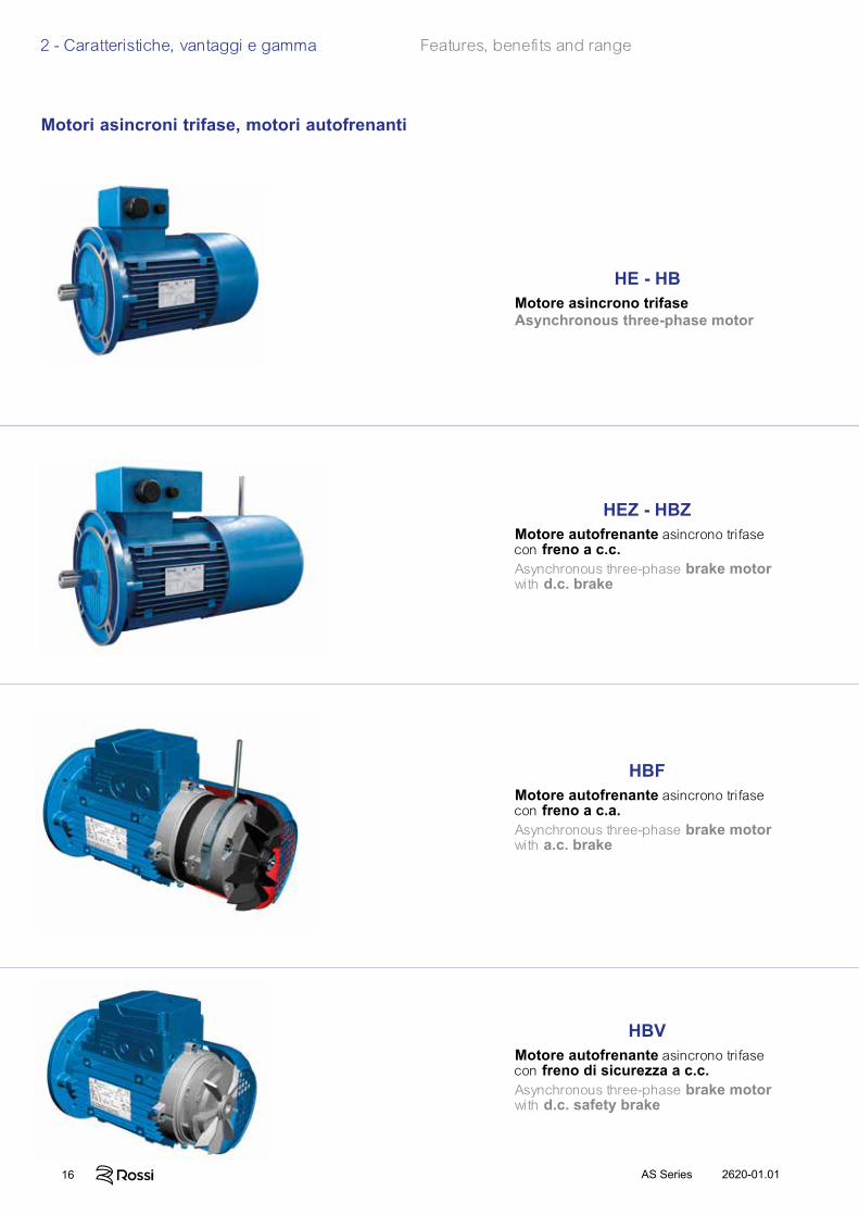
HE - HBMotore asincrono trifaseAsynchronous three-phase motor
HEZ - HBZMotore autofrenante asincrono trifase con freno a c.c.Asynchronous three-phase brake motor with d.c. brake
HBFMotore autofrenante asincrono trifase con freno a c.a.Asynchronous three-phase brake motor with a.c. brake
HBVMotore autofrenante asincrono trifase con freno di sicurezza a c.c.Asynchronous three-phase brake motor with d.c. safety brake
Motori asincroni trifase, motori autofrenanti
172620-01.01 AS Series
2 - Caratteristiche, vantaggi e gamma Features, benefits and range
In virtù delle elevate caratteristiche di silenziosità, progressività e dinamicità trova il suo campo di applicazione tipico nell’accoppiamento con motoriduttore poichè minimizza i sovraccarichi dinamiciderivanti dalle fasi di avviamento e frenatura (soprattutto in caso di inversioni di moto) pur garantendo un ottimo valore di momento frenante.L'eccellente progressività di intervento - sia all'avviamento che in frenatura - è assicurata dall'àncora meno veloce nell'impatto (rispetto al tipo in corrente alternata HBF), nonchè dalla moderata prontezza di risposta propria dei freni a c.c.Dispone, inoltre, della più ampia scelta di accessori ed esecuzioni speciali per soddisfare al meglio la vasta tipologia di applicazioni cui può essere destinato il motoriduttore.
Thanks to its outstanding low noise, progressivity and dynamic characteristics, it is specifically suitable for coupling with gearmotor minimizing the dynamic overloads deriving from starting and braking phases (especially in case of motion reversals) and maintaining a very good braking torque value.The excellent operation progressivity - when starting and braking - is assured by the brake anchor which is less quick in the impact (compared to a.c. HBF) and by the slight quickness of d.c. brakes.Offering a comprehensive range of accessories and non-standard designs in order to satisfy all possible gearmotor application fields.
L’estrema reattività tipica dei freni a c.a. e l’elevata capacità di lavoro di frenatura ne fanno un motore autofrenante particolarmente idoneo per servizi gravosi nei quali siano richieste frenature rapidenonchè elevato numero di interventi (es.: sollevamenti con alta frequenza di interventi, che normalmente si verifica per grand. 132, e/o con marcia a impulsi).Viceversa le sue elevate caratteristiche dinamiche (rapidità e frequenza di intervento) generalmente ne sconsigliano l’uso in accoppiamento con il motoriduttore soprattutto quando queste prerogative non siano strettamente necessarie per l’applicazione (onde evitare di generare inutili sovraccarichi sulla trasmissione nel suo complesso).Dispone, inoltre, della più ampia scelta di accessori ed esecuzioni speciali per soddisfare al meglio la vasta tipologia di applicazioni cui può essere destinato il motoriduttore (in particolare per HBF: IP 56, IP 65, encoder, servoventilatore, servoventilatore ed encoder, seconda estremità d’albero, ecc.).
The high reactivity typical of a.c. brake and the high brakingcapacity make this brake motor particularly suitable for heavy duties requiring quick brakings and a high number of operations(e.g.: lifts with high frequency of starting, usually for size 132, and/or for jog operations).Vice versa, its very high dynamic characteristics (rapidity and frequency of starting) are not advisable for the use in gearmotorcoupling, especially when these features are not strictly necessary for the application (avoiding useless overloads on the whole transmission).Comprehensive range of accessories and non-standard designsin order to satisfy all application needs of gearmotors (in particular for HBF: IP 56, IP 65, encoder, independent cooling fan, independent cooling fan and encoder, double extension shaft, etc.).
Caratterizzato da massima economicità, ingombri ridottissimi e momento frenante moderato, è idoneo all'accoppiamento con motoriduttore e trova il suo campo di applicazione tipico laddove sia richiesto un freno per arresti di sicurezza o di stazionamento in generale (es.: macchine da taglio) e per interventi al termine della rampa di decelerazione nel funzionamento con inverter.Inoltre, la ventola di ghisa di cui è provvisto di serie, fornisce un effetto volano che aumenta la già ottima progressività di avviamento e di frenatura tipiche del freno a c.c. e lo rende particolarmente indicato anche per traslazioni «leggere»1) .
1) Gruppo di meccanismo M 4 (max 180 avv./h) e regime di carico L 1 (leggero) o L 2 (moderato) secondo ISO 4301/1, F.E.M./II 1997.
Featuring maximum economy, very reduced overall dimensions and moderate braking torque, it is suitable for the coupling with gearmotor and can be applied as brake for safety or parking stops(e.g. cutting machines) and for operations at deceleration ramp end during the running with inverter.The standard cast iron fan supplies a flywheel effect increasing the very good progressivity of starting and braking (typical of d.c. brake) being particularly suitable for «light»1) traverse movements.
1) Mechanism group M4 (max 180 starts/h) and on-load running L1 (light) or L2 (moderate) to ISO 4301/1, F.E.M./II 1997.
Advanced design motors sharing the same stator windings, the same rotors, the same housings, the same flanges, the same performance, and the majority of technical solutions with its twin brake motor series (HEZ, HBZ, HBF, and HBV).The generous electromagnetic sizing allow to achieve high efficiency values complying with different energy saving regulations:– Efficiency class IE3 (ErP) for HB and HE;– Efficiency class IE3 (ErP) for HEZ, on request for HBZThe electric design (terminal block, name plate, etc.) has been studied to comply, as standard, also with NEMA MG1-12 for the maximum application flexibility and facility.The strength and the precision of mechanical construction, the generous bearings and the wide range of non-standard designs available on catalog make this motor particularly suitable for coupling with gearmotors.
Asynchronous three-phase motors, brake motors
Motore di avanzata concezione che condivide con le serie gemelle di motori autofrenanti (HEZ, HBZ, HBF e HBV) gli stessi pacchi statorici, gli stessi rotori, le stesse carcasse, le stesse flange, le stesse prestazioni e la maggioranza delle soluzioni tecniche.Il dimensionamento elettromagnetico generoso consente, elevati valori di rendimento in conformità alle diverse direttive in materia di risparmio energetico:– Classe di efficienza IE3 (ErP) per HB e HE;
– Classe di efficienza IE3 (ErP) per HEZ, a richiesta per HBZLa parte elettrica (morsettiera, targa, ecc.) è stata progettata per essere di serie conforme anche a NEMA MG1-12 per la massima universalità e facilità di applicazione.La robustezza e la precisione della costruzione meccanica, i cuscinetti generosi e l'ampia gamma di esecuzioni speciali disponibili a catalogo ne fanno un motore particolarmente adatto all'accoppiamento con motoriduttori di velocità.
18 2620-01.01AS Series
Simboli e unità di misura Symbols and units of measureSimboli in ordine alfabetico, con relative unità di misura, impiegati nel catalogo e nelle formule.
Symbols used in the catalogue and formulae, in alphabetical order, with relevant units of measure.
Simbolo Espressione Unità di misura Note Symbol Definition Units of measure Notes Nel catalogo Nelle formule In the In the formulae catalogue Sistema Tecnico Sistema SI1)
Technical System SI1) System
dimensioni, quote dimensions mm –a accelerazione acceleration – m/s2
d diametro diameter – mf frequenza frequency Hz Hzfs fattore di servizio service factorf t fattore termico thermal factorF forza force – kgf N2) 1 kgf ≈ 9,81 N ≈ 0,981 daNFr carico radiale radial load daN –Fa carico assiale axial load daN –g accelerazione di gravità acceleration of gravity – m/s2 val. norm. 9,81 m/s2 normal value 9,81 m/s2
G peso (forza peso) weight (weight force) – kgf NGd 2 momento dinamico dynamic moment – kgf m2 –
i rapporto di trasmissione transmission ratio i =
n1
n2
I corrente elettrica electric current – AJ momento d’inerzia moment of inertia kg m2 – kg m2
Lh durata dei cuscinetti bearing life h –m massa mass kg kgf s2/m kg3)
M momento torcente torque daN m kgf m N m 1 kgf m ≈ 9,81 N m ≈ 0,981 daN m
n velocità angolare speed min-1 giri/min – 1 min-1 ≈ 0,105 rad/s rev/min
P potenza power kW CV W 1 CV ≈ 736 W ≈ 0,736 kWP t potenza termica thermal power kW –r raggio radius – m
R rapporto di variazione variation ratio R =
n2 max
n2 min
s spazio distance – mt temperatura Celsius Celsius temperature °C –t tempo time s s
min 1 min = 60 s h 1 h = 60 min = 3 600 s d 1 d = 24 h = 86 400 s
U tensione elettrica voltage V Vv velocità velocity – m/sW lavoro, energia work, energy MJ kgf m J4)
z frequenza di avviamento frequency of starting avv./h – starts/h
accelerazione angolare angular acceleration – rad/s2
rendimento efficiencys rendimento statico static efficiency coefficiente di attrito friction coefficient angolo piano plane angle ° rad 1 giro = 2 rad 1 rev = 2 rad
1° =
rad
velocità angolare angular velocity – – rad/s 1 rad/s ≈ 9,55 min-1
Indici aggiuntivi e altri segni Additional indexes and other signs
1) SI è la sigla del Sistema Internazionale di Unità, definito ed approvato dalla Conferen-za Gene-rale dei Pesi e Misure quale unico sistema di unità di misura.
Ved. CNR UNI 10 003-84 (DIN 1 301-93 NF X 02.004, BS 5 555-93, ISO 1 000-92). UNI: Ente Nazionale Italiano di Unificazione. DIN: Deutscher Normenausschuss (DNA). NF: Association Française de Normalisation (AFNOR). BS: British Standards Institution (BSI). ISO: International Organization for Standardization.2) Il newton [N] è la forza che imprime a un corpo di massa 1 kg l’accelerazione di 1 m/s2.3) Il kilogrammo [kg] è la massa del campione conservato a Sèvres (ovvero di 1 dm3 di acqua
distillata a 4 °C).4) Il joule [J] è il lavoro compiuto dalla forza di 1 N quando si sposta di 1 m.
1) SI are the initials of the International Unit System, defined and approved by the General Conference on Weights and Measures as the only system of units of measure.
Ref. CNR UNI 10 003-84 (DIN 1 301-93 NF X 02.004, BS 5 555-93, ISO 1 000-92). UNI: Ente Nazionale Italiano di Unificazione. DIN: Deutscher Normenausschuss (DNA). NF: Association Française de Normalisation (AFNOR). BS: British Standards Institution (BSI). ISO: International Organization for Standardization.2) Newton [N] is the force imparting an acceleration of 1 m/s2 to a mass of 1 kg.3) Kilogramme [kg] is the mass of the prototype kept at Sèvres (i.e. 1 dm3 of distilled water at 4
°C).4) Joule [J] is the work done when the point of application of a force of 1 N is displaced through
a distance of 1 m.
Ind. Espressione Definition
max massimo maximum min minimo minimum N nominale nominal 1 relativo all’asse veloce (entrata) relating to high speed shaft (input) 2 relativo all’asse lento (uscita) relating to low speed shaft (output)
da ... a from ... to≈ uguale a circa approximately equal to maggiore o uguale a greater than or equal to minore o uguale a less than or equal to
180
Simbolo Espressione Unità di misura Note Simbolo Espressione Unità di misura Note Simbolo Espressione Unità di misura Note Simbolo Espressione Unità di misura Note Symbol Definition Units of measure Notes Symbol Definition Units of measure Notes Symbol Definition Units of measure Notes Symbol Definition Units of measure Notes Nel catalogo Nelle formule Nel catalogo Nelle formule Nel catalogo Nelle formule Nel catalogo Nelle formule In the In the formulae In the formulae catalogue Sistema Tecnico Sistema SI Sistema SI1)
Technical System SI1) System
dimensioni, quote a
d f fsfsff t fattore termico f t fattore termico fF FrFrF carico radiale FaFaF carico assiale g G
Gd 2 momento dinamico
i I
J Lh durata dei cuscinetti m massa M momento torcente M momento torcente M
n velocità angolare P
P t potenza termica r
R
s t temperatura Celsius t temperatura Celsius tt tempo t tempo t
min 1 min = 60 s h 1 h = 60 min = 3 600 s d 1 d = 24 h = 86 400 s
U v velocità v velocità vW lavoro, energia W lavoro, energia W
z
rendimento s rendimento statico coefficiente di attrito angolo piano
velocità angolare
Ind. Espressione DefinitionInd. Espressione DefinitionInd. Espressione Definition
max massimo min minimo N nominale 1 relativo all’asse veloce (entrata) 2 relativo all’asse lento (uscita)
max massimo min minimo N nominale 1 relativo all’asse veloce (entrata) 2 relativo all’asse lento (uscita)
da ... a ≈ uguale a circa maggiore o uguale a minore o uguale a
max massimo min minimo N nominale 1 relativo all’asse veloce (entrata) 2 relativo all’asse lento (uscita)
da ... a uguale a circa maggiore o uguale a minore o uguale a
Ind. Espressione DefinitionInd. Espressione DefinitionInd. Espressione Definition

192620-01.01 AS Series
20 2620-01.01AS Series
3
Panoramica del prodotto
20 2620-01.01AS Series20 2620-01.01AS Series
212620-01.01 AS Series
Section content
3.1 Designazione Designation 22
3.2 Forme costruttive e lubrifi cazione Mounting positions and lubrication 24
3.3 Potenza termica Thermal power 25
3.4 Fattore di servizio Service factor 26
3.5 Scelta Selection 27
3.6 Carichi radiali sull’estremità d’albero lento Radial loads on low speed shaft end 28
3.7 Tabelle di selezione Selection tables 29
3.8 Dimensioni Dimensions 37
3.9 Dettagli costruttivi e funzionali Structural and operational details 43
Product overview
212620-01.01 AS Series
22 2620-01.01AS Series
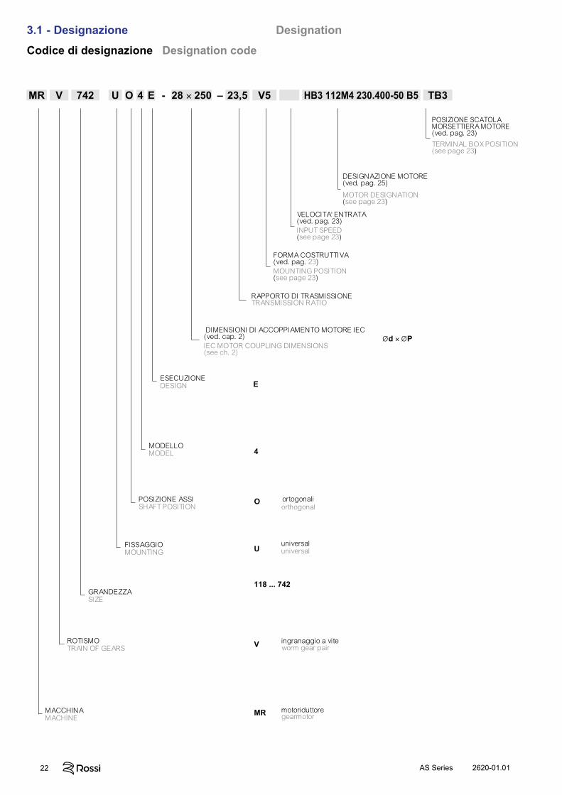
3.1 - Designazione DesignationCodice di designazione Designation code
MR V 742 U O 4 E - 28 × 250 – 23,5 V5 HB3 112M4 230.400-50 B5 TB3
motoriduttoregearmotor
MACCHINAMACHINE
ingranaggio a viteworm gear pair
ROTISMOTRAIN OF GEARS
118 ... 742GRANDEZZASIZE
universaluniversal
FISSAGGIOMOUNTING
ortogonaliorthogonal
POSIZIONE ASSI SHAFT POSITION
4
O
U
V
MR
E
MODELLOMODEL
ESECUZIONEDESIGN
Ød × ØP DIMENSIONI DI ACCOPPIAMENTO MOTORE IEC (ved. cap. 2)IEC MOTOR COUPLING DIMENSIONS(see ch. 2)
RAPPORTO DI TRASMISSIONETRANSMISSION RATIO
FORMA COSTRUTTIVA(ved. pag. 23)MOUNTING POSITION(see page 23)
DESIGNAZIONE MOTORE(ved. pag. 25)
MOTOR DESIGNATION(see page 23)
VELOCITA' ENTRATA(ved. pag. 23)INPUT SPEED(see page 23)
POSIZIONE SCATOLAMORSETTIERA MOTORE(ved. pag. 23)
TERMINAL BOX POSITION(see page 23)
232620-01.01 AS Series
3.1 - Designazione Designation
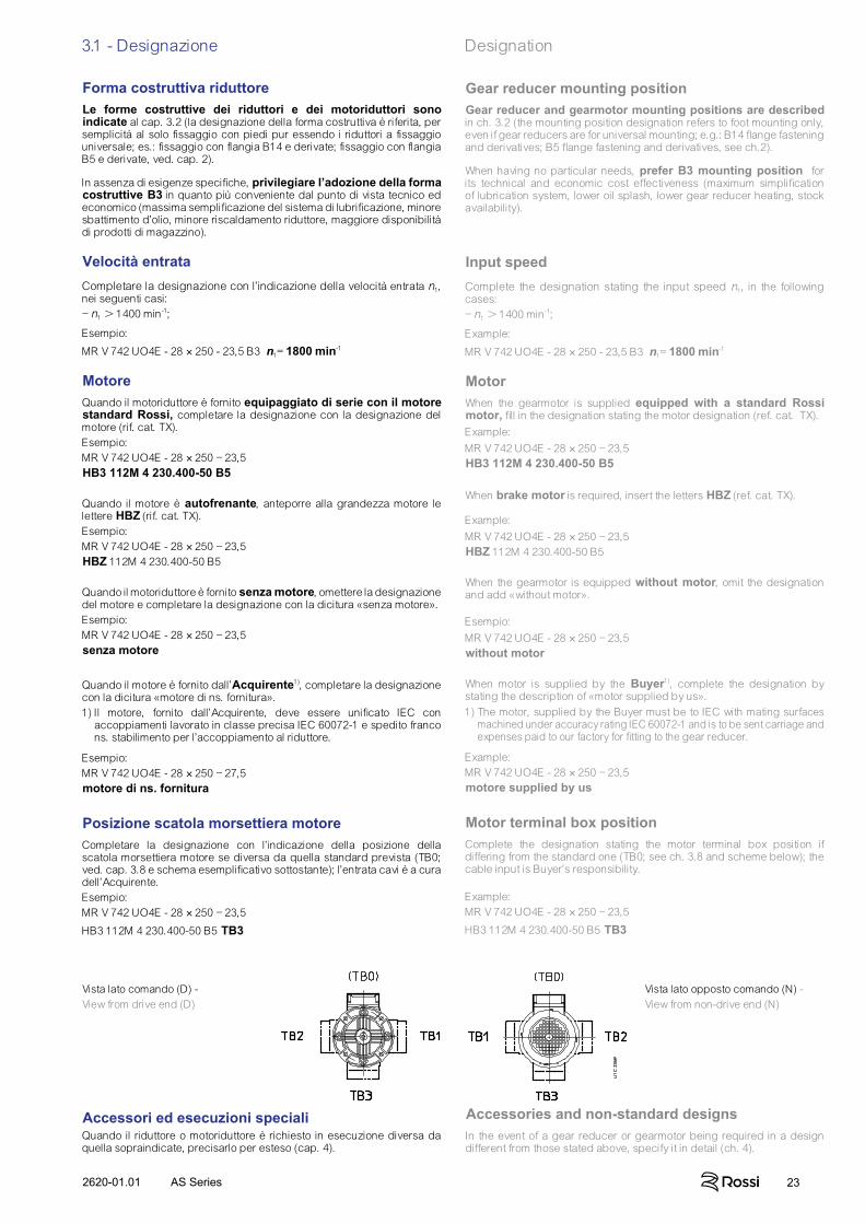
Forma costruttiva riduttoreLe forme costruttive dei riduttori e dei motoriduttori sono indicate al cap. 3.2 (la designazione della forma costruttiva è riferita, per semplicità al solo fissaggio con piedi pur essendo i riduttori a fissaggio universale; es.: fissaggio con flangia B14 e derivate; fissaggio con flangia B5 e derivate, ved. cap. 2).
In assenza di esigenze specifiche, privilegiare l’adozione della forma costruttive B3 in quanto più conveniente dal punto di vista tecnico ed economico (massima semplificazione del sistema di lubrificazione, minore sbattimento d’olio, minore riscaldamento riduttore, maggiore disponibilità di prodotti di magazzino).
Velocità entrataCompletare la designazione con l’indicazione della velocità entrata n1, nei seguenti casi:– n1 1400 min-1;
Esempio:
MR V 742 UO4E - 28 × 250 - 23,5 B3 n1= 1800 min-1
MotoreQuando il motoriduttore è fornito equipaggiato di serie con il motore standard Rossi, completare la designazione con la designazione del motore (rif. cat. TX).Esempio:MR V 742 UO4E - 28 × 250 – 23,5HB3 112M 4 230.400-50 B5
Quando il motore è autofrenante, anteporre alla grandezza motore le lettere HBZ (rif. cat. TX).Esempio:MR V 742 UO4E - 28 × 250 – 23,5HBZ 112M 4 230.400-50 B5
Quando il motoriduttore è fornito senza motore, omettere la designazione del motore e completare la designazione con la dicitura «senza motore».Esempio:MR V 742 UO4E - 28 × 250 – 23,5senza motore
Quando il motore è fornito dall’Acquirente1), completare la designazione con la dicitura «motore di ns. fornitura».1) Il motore, fornito dall’Acquirente, deve essere unificato IEC con
accoppiamenti lavorato in classe precisa IEC 60072-1 e spedito franco ns. stabilimento per l’accoppiamento al riduttore.
Esempio:MR V 742 UO4E - 28 × 250 – 27,5motore di ns. fornitura
Posizione scatola morsettiera motoreCompletare la designazione con l’indicazione della posizione della scatola morsettiera motore se diversa da quella standard prevista (TB0; ved. cap. 3.8 e schema esemplificativo sottostante); l’entrata cavi è a cura dell’Acquirente.Esempio:MR V 742 UO4E - 28 × 250 – 23,5
HB3 112M 4 230.400-50 B5 TB3
Accessori ed esecuzioni specialiQuando il riduttore o motoriduttore è richiesto in esecuzione diversa da quella sopraindicate, precisarlo per esteso (cap. 4).
Gear reducer mounting positionGear reducer and gearmotor mounting positions are described in ch. 3.2 (the mounting position designation refers to foot mounting only, even if gear reducers are for universal mounting; e.g.: B14 flange fastening and derivatives; B5 flange fastening and derivatives, see ch.2).
When having no particular needs, prefer B3 mounting position for its technical and economic cost effectiveness (maximum simplification of lubrication system, lower oil splash, lower gear reducer heating, stock availability).
Input speedComplete the designation stating the input speed n1, in the following cases:– n1 1400 min-1;
Example:
MR V 742 UO4E - 28 × 250 - 23,5 B3 n1= 1800 min-1
MotorWhen the gearmotor is supplied equipped with a standard Rossi motor, fill in the designation stating the motor designation (ref. cat. TX).Example:MR V 742 UO4E - 28 × 250 – 23,5HB3 112M 4 230.400-50 B5
When brake motor is required, insert the letters HBZ (ref. cat. TX).
Example:MR V 742 UO4E - 28 × 250 – 23,5HBZ 112M 4 230.400-50 B5
When the gearmotor is equipped without motor, omit the designation and add «without motor».
Esempio:MR V 742 UO4E - 28 × 250 – 23,5without motor
When motor is supplied by the Buyer1), complete the designation by stating the description of «motor supplied by us».1) The motor, supplied by the Buyer must be to IEC with mating surfaces
machined under accuracy rating IEC 60072-1 and is to be sent carriage and expenses paid to our factory for fitting to the gear reducer.
Example:MR V 742 UO4E - 28 × 250 – 23,5motore supplied by us
Motor terminal box positionComplete the designation stating the motor terminal box position if differing from the standard one (TB0; see ch. 3.8 and scheme below); the cable input is Buyer’s responsibility.
Example:MR V 742 UO4E - 28 × 250 – 23,5
HB3 112M 4 230.400-50 B5 TB3
Vista lato comando (D) - View from drive end (D)
Vista lato opposto comando (N) - View from non-drive end (N)
Accessories and non-standard designsIn the event of a gear reducer or gearmotor being required in a design different from those stated above, specify it in detail (ch. 4).
24 2620-01.01AS Series
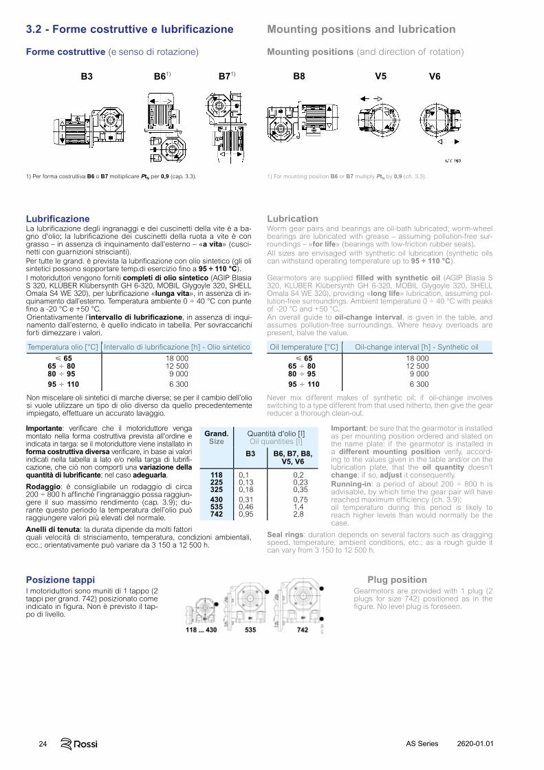
3.2 - Forme costruttive e lubrificazione Mounting positions and lubrication
Forme costruttive (e senso di rotazione) Mounting positions (and direction of rotation)
Worm gear pairs and bearings are oil-bath lubricated; worm-wheel bearings are lubricated with grease – assuming pollution-free sur-roundings – «for life» (bearings with low-friction rubber seals).All sizes are envisaged with synthetic oil lubrication (synthetic oils can withstand operating temperature up to 95 ÷ 110 °C).
Gearmotors are supplied filled with synthetic oil (AGIP Blasia S 320, KLÜBER Klübersynth GH 6-320, MOBIL Glygoyle 320, SHELL Omala S4 WE 320), providing «long life» lubrication, assuming pol-lution-free surroundings. Ambient temperature 0 ÷ 40 °C with peaks of -20 °C and +50 °C.
Oil temperature [°C] Oil-change interval [h] - Synthetic oil
65 18 00065 800 12 50080 950 9 00095 110 6 300
An overall guide to oil-change interval, is given in the table, and assumes pollution-free surroundings. Where heavy overloads are present, halve the value.
Never mix different makes of synthetic oil; if oil-change involvesswitching to a type different from that used hitherto, then give the gear reducer a thorough clean-out.
Important: be sure that the gearmotor is installed as per mounting position ordered and stated on the name plate: if the gearmotor is installed in a different mounting position verify, accord-ing to the values given in the table and/or on the lubrication plate, that the oil quantity doesn't change; if so, adjust it consequently.Running-in: a period of about 200 ÷ 800 h is advisable, by which time the gear pair will have reached maximum efficiency (ch. 3.9);oil temperature during this period is likely to reach higher levels than would normally be the case.
Seal rings: duration depends on several factors such as dragging speed, temperature, ambient conditions, etc.; as a rough guide it can vary from 3 150 to 12 500 h.
Lubrificazione LubricationLa lubrificazione degli ingranaggi e dei cuscinetti della vite è a ba-gno d'olio; la lubrificazione dei cuscinetti della ruota a vite è con grasso – in assenza di inquinamento dall'esterno – «a vita» (cusci-netti con guarnizioni striscianti).Per tutte le grand. è prevista la lubrificazione con olio sintetico (gli oli sintetici possono sopportare temp.di esercizio fino a 95 ÷ 110 °C).I motoriduttori vengono forniti completi di olio sintetico (AGIP Blasia S 320, KLÜBER Klübersynth GH 6-320, MOBIL Glygoyle 320, SHELL Omala S4 WE 320), per lubrificazione «lunga vita», in assenza di in-quinamento dall’esterno. Temperatura ambiente 0 ÷ 40 °C con punte fino a -20 °C e +50 °C.
Temperatura olio [°C] Intervallo di lubrificazione [h] - Olio sintetico
65 18 00065 800 12 50080 950 9 00095 110 6 300
Orientativamente l’intervallo di lubrificazione, in assenza di inqui-namento dall’esterno, è quello indicato in tabella. Per sovraccarichi forti dimezzare i valori.
Non miscelare oli sintetici di marche diverse; se per il cambio dell’olio si vuole utilizzare un tipo di olio diverso da quello precedentemente impiegato, effettuare un accurato lavaggio.
Importante: verificare che il motoriduttore venga montato nella forma costruttiva prevista all'ordine e indicata in targa: se il motoriduttore viene installato in forma costruttiva diversa verificare, in base ai valori indicati nella tabella a lato e/o nella targa di lubrifi-cazione, che ciò non comporti una variazione della quantità di lubrificante; nel caso adeguarla.
Rodaggio: è consigliabile un rodaggio di circa 200 ÷ 800 h affinché l’ingranaggio possa raggiun-gere il suo massimo rendimento (cap. 3.9); du-rante questo periodo la temperatura dell’olio può raggiungere valori più elevati del normale.
Anelli di tenuta: la durata dipende da molti fattori quali velocità di strisciamento, temperatura, condizioni ambientali, ecc.; orientativamente può variare da 3 150 a 12 500 h.
Grand.Size
Quantità d'olio [l]Oil quantities [l]
B3 B6, B7, B8, V5, V6
118 0,1 0,2225 0,13 0,23325 0,18 0,35430 0,31 0,75535 0,46 1,4742 0,95 2,8
Posizione tappi Plug positionI motoriduttori sono muniti di 1 tappo (2 tappi per grand. 742) posizionato come indicato in figura. Non è previsto il tap-po di livello.
Gearmotors are provided with 1 plug (2 plugs for size 742) positioned as in the figure. No level plug is foreseen.
B3 B61) B71) B8 V5 V6
1) Per forma costruttiva B6 o B7 moltiplicare PtN per 0,9 (cap. 3.3). 1) For mounting position B6 or B7 multiply PtN by 0,9 (ch. 3.3).
Temperatura olio [°C] Intervallo di lubrificazione [h] - Olio sintetico Temperatura olio [°C] Intervallo di lubrificazione [h] - Olio sintetico Temperatura olio [°C] Intervallo di lubrificazione [h] - Olio sintetico Oil temperature [°C] Oil-change interval [h] - Synthetic oil Oil temperature [°C] Oil-change interval [h] - Synthetic oil Oil temperature [°C] Oil-change interval [h] - Synthetic oil
252620-01.01 AS Series
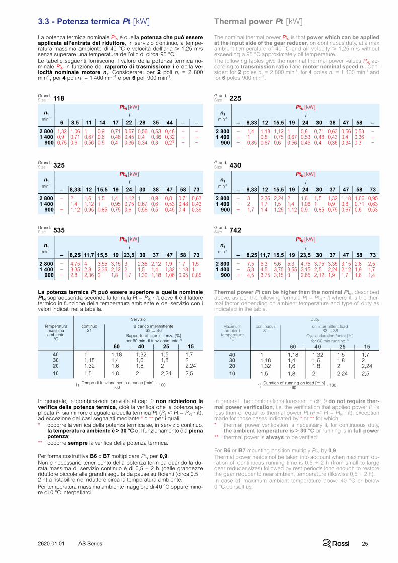
3.3 - Potenza termica Pt [kW] Thermal power Pt [kW]
La potenza termica nominale PtN è quella potenza che può essere applicata all’entrata del riduttore, in servizio continuo, a tempe-ratura massima ambiente di 40 °C e velocità dell’aria 1,25 m/s senza superare una temperatura dell’olio di circa 95 °C.Le tabelle seguenti forniscono il valore della potenza termica no-minale PtN in funzione del rapporto di trasmissione i e della ve-locità nominale motore n1. Considerare: per 2 poli n1 = 2 800min-1, per 4 poli n1 = 1 400 min-1 e per 6 poli 900 min-1.
The nominal thermal power PtN is that power which can be applied at the input side of the gear reducer, on continuous duty, at a max ambient temperature of 40 °C and air velocity 1,25 m/s without exceeding a 95 °C approximately oil temperature.The following tables give the nominal thermal power values PtN ac-cording to transmission ratio i and motor nominal speed n1. Con-sider: for 2 poles n1 = 2 800 min-1, for 4 poles n1 = 1 400 min-1 and for 6 poles 900 min-1.
n1min-1
PtN [kW]
i6 8,5 11 14 17 22 28 35 44 – –
2 800 1,32 1,06 1 0,9 0,71 0,67 0,56 0,53 0,48 − −1 400 0,9 0,71 0,67 0,6 0,48 0,45 0,4 0,36 0,32 − −
900 0,75 0,6 0,56 0,5 0,4 0,36 0,34 0,3 0,27 − −
n1min-1
PtN [kW]
i– 8,33 12 15,5 19 24 30 38 47 58 73
2 800 − 2 1,6 1,5 1,4 1,12 1 0,9 0,8 0,71 0,631 400 − 1,4 1,12 1 0,95 0,75 0,67 0,6 0,53 0,48 0,43
900 − 1,12 0,95 0,85 0,75 0,6 0,56 0,5 0,45 0,4 0,36
n1min-1
PtN [kW]
i– 8,25 11,7 15,5 19 23,5 30 37 47 58 73
2 800 − 4,75 4 3,55 3,15 3 2,36 2,12 1,9 1,7 1,51 400 − 3,35 2,8 2,36 2,12 2 1,5 1,4 1,32 1,18 1
900 − 2,8 2,36 2 1,8 1,7 1,32 1,18 1,06 0,95 0,85
n1min-1
PtN [kW]
i– 8,33 12 15,5 19 24 30 38 47 58 –
2 800 − 1,4 1,18 1,12 1 0,8 0,71 0,63 0,56 0,53 −1 400 − 1 0,8 0,75 0,67 0,53 0,48 0,43 0,4 0,36 −
900 − 0,85 0,67 0,6 0,56 0,45 0,4 0,36 0,34 0,3 −
n1min-1
PtN [kW]
i– 8,33 12 15,5 19 24 30 37 47 58 73
2 800 − 3 2,36 2,24 2 1,6 1,5 1,32 1,18 1,06 0,951 400 − 2 1,7 1,5 1,4 1,06 1 0,9 0,8 0,71 0,63
900 − 1,7 1,4 1,25 1,12 0,9 0,85 0,75 0,67 0,6 0,53
n1min-1
PtN [kW]
i– 8,25 11,7 15,5 19 23,5 30 37 47 58 73
2 800 − 7,5 6,3 5,6 5,3 4,75 3,75 3,35 3,15 2,8 2,51 400 − 5,3 4,5 3,75 3,55 3,15 2,5 2,24 2,12 1,9 1,7
900 − 4,5 3,75 3,15 3 2,65 2,12 1,9 1,7 1,6 1,4
118Grand.Size
325Grand.Size
535Grand.Size
225Grand.Size
430Grand.Size
742Grand.Size
La potenza termica Pt può essere superiore a quella nominale PtN sopradescritta secondo la formula Pt = PtN · ft dove ft è il fattore termico in funzione della temperatura ambiente e del servizio con i valori indicati nella tabella.
In generale, le combinazioni previste al cap. 9 non richiedono la verifica della potenza termica, cioè la verifica che la potenza ap-plicata P1 sia minore o uguale a quella termica Pt (P1 Pt = PtN · ft), ad eccezione dei casi segnalati mediante * o ** per i quali:* occorre la verifica della potenza termica se, in servizio continuo,
la temperatura ambiente è > 30 °C o il funzionamento è a piena potenza;
** occorre sempre la verifica della potenza termica.
Per forma costruttiva B6 o B7 moltiplicare PtN per 0,9.Non è necessario tener conto della potenza termica quando la du-rata massima di servizio continuo è di 0,5 ÷ 2 h (dalle grandezze riduttore piccole alle grandi) seguita da pause sufficienti (circa 0,5 ÷ 2 h) a ristabilire nel riduttore circa la temperatura ambiente.Per temperatura massima ambiente maggiore di 40 °C oppure mino-re di 0 °C interpellarci.
Thermal power Pt can be higher than the nominal PtN, described above, as per the following formula Pt = PtN · ft where ft is the ther-mal factor depending on ambient temperature and type of duty as indicated in the table.
In general, the combinations foreseen in ch. 9 do not require ther-mal power verification, i.e. the verification that applied power P1 is less than or equal to thermal power Pt (P1 Pt = PtN · ft), exception made for those cases indicated by * or ** for which:* thermal power verification is necessary if, for continuous duty,
the ambient temperature is > 30 °C or running is in full power** thermal power is always to be verified
For B6 or B7 mounting position multiply PtN by 0,9.Thermal power needs not be taken into account when maximum du-ration of continuous running time is 0,5 ÷ 2 h (from small to large gear reducer sizes) followed by rest periods long enough to restore the gear reducer to near ambient temperature (likewise 0,5 ÷ 2 h).In case of maximum ambient temperature above 40 °C or below0 °C consult us.
Servizio
Temperaturamassimaambiente
°C
continuoS1
a carico intermittenteS3 ... S6
Rapporto di intermittenza [%]per 60 min di funzionamento 1)
60 40 25 1540 1,00 1,18 1,32 1,50 1,7030 1,18 1,40 1,60 1,80 2,0020 1,32 1,60 1,80 2,00 2,2410 1,50 1,80 2,00 2,24 2,50
1) Tempo di funzionamento a carico [min]60
· 100
Maximumambient
temperature°C
continuousS1
on intermittent loadS3 ... S6
Cyclic duration factor [%]for 60 min running 1)
60 40 25 15
Duty
40 1,00 1,18 1,32 1,50 1,7030 1,18 1,40 1,60 1,80 2,0020 1,32 1,60 1,80 2,00 2,2410 1,50 1,80 2,00 2,24 2,50
1) Duration of running on load [min]60
· 100
40302010
Maximumambient
temperature°C
continuousS1
on intermittent loadS3 ... S6
Cyclic duration factor [%]for 60 min running 1)
60 40 25 1560 40 25 1560 40 25 1560 40 25 15
Duty
40302010
26 2620-01.01AS Series
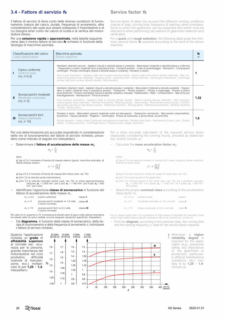
3.4 - Fattore di servizio fs Service factor fs
Il fattore di servizio fs tiene conto delle diverse condizioni di funzio-namento (natura del carico, durata, frequenza di avviamento, altre considerazioni) alle quali può essere sottoposto il motoriduttore e di cui bisogna tener conto nei calcoli di scelta e di verifica del motori-duttore stesso.Per una selezione rapida e approssimata, nella tabella seguente viene dato il minimo fattore di servizio fs richiesto in funzione della tipologia di macchina azionata.
Service factor fs takes into account the different running conditions (nature of load, running time, frequency of starting, other considera-tions) to which the gearmotor can be subjected and which must be referred to when performing calculations of gearmotor selection and verification.For a quick and rough selection, the following table gives the mini-mum service factor fs required according to the kind of the driven machine.
Per una determinazione più accurata (soprattutto in considerazione delle ore di funzionamento) del fattore di servizio richiesto, proce-dere come indicato di seguito e/o interpellarci.
For a more accurate calculation of the required service factor (especially considering the running hours), proceed as stated be-low and/or consult us.
− Determinare il fattore di accelerazione delle masse mJ:
dove:
J1 [kg m2] è il momento d’inerzia (di massa) esterno (giunti, macchina azionata), J, riferito all’asse motore:
J0 [kg m2] è il momento d’inerzia (di massa) del motore (ved. cat. TX);
n2 [min-1] è la velocità uscita motoriduttore;
nN [min-1] è la velocità nominale motore (ved. cat. TX). In prima approssimazione utilizzare: nN = 2 800 min-1 per 2 poli; nN = 1 400 min-1 per 4 poli; nN = 900 min-1 per 6 poli.
− Identificare l'opportuna classe di sovraccarico in funzione del fattore di accelerazione delle masse mJ
mJ 0,3 (carico uniforme) classe I
mJ 3 (sovraccarichi moderati: ≈ 1,6 volte il carico normale)
classe II
mJ 10 (sovraccarichi forti: ≈ 2,5 volte il carico normale)
classe III
Per valori di mJ superiori a 10, in presenza di elevati valori di gioco nella catena cinematica e/o elevati valori di carico radiale, occorre eseguire valutazioni specifiche: interpellarci.
− Dal diagramma, in funzione della classe di sovraccarico, della du-rata di funzionamento e della frequenza di avviamento z, individuare il fattore di servizio richiesto.
mJ =J1
J0
J1 = J .n2
nN
2
( )
− Calculate the mass acceleration factor mJ:
where:
J1 [kg m2] is the external moment of inertia J (of mass; coupling, driven machine), referred to motor shaft:
J0 [kg m2] is the moment of inertia (of mass) of motor (see. cat. TX);
n2 [min-1] is output speed of the gearmotor;
nN [min-1] is nominal speed of the motor (see. cat. TX). As a guideline consider: nN = 2 800 min-1 for 2 poles; nN = 1 400 min-1 for 4 poles; nN = 900 min-1 for 6 poles.
− Select the proper overload class according to the acceleration mass factor mJ
mJ 0,3 (uniform load) class I
mJ 3 (moderate overloads: ≈ 1,6 x normal)
class II
mJ 10 (heavy overloads: ≈ 2,5 x normal)
class III
For mJ values higher than 10, in presence of high values of backlash for kinematic chain and/or high radial loads a specific evaluation has to be carried out: consult us.
− From the diagram, according to the overload class, the running time and the starting frequency z, read off the service factor required.
mJ =J1
J0
J1 = J .n2
nN
2
( )
Classificazione del caricoLoad classification
Macchina azionataDriven machine
fs
ICarico uniformeUniform load(mJ 0,3)
Ventilatori (diametri piccoli) - Agitatori (liquidi a densità bassa e costante) - Mescolatori (materiali a densità bassa e uniforme) - Trasporatori a nastro (materiali sfusi a pezzatura fine) - Comandi ausiliari - Linee di assemblaggio - Riempitrici - Compressori centrifughi - Pompe centrifughe (liquidi a densità bassa e costante) - Elevatori a nastro.
Fans (small diameters) - Agitators (light and constant density liquids) - Mixers (light and uniform density materials) - Belt con-veyors (fine grade loose materials) - Auxiliary drives - Assembly lines - Filling machines - Centrifugal compressors - Centrifugal pumps (light and constant density liquids) - Belt elevators.
1
IISovraccarichi moderatiModerate overloads(mJ 3)
Ventilatori (diametri medi) - Agitatori (liquidi a densità elevata o variabile) - Mescolatori (materiali a densità variabile) - Traspor-tatori a nastro (materiali sfusi a pezzatura grossa) - Traslazione - Pompe dosatrici - Pompe a ingranaggi - Pompe a pistoni pluricilindriche - Pompe centrifughe (liquidi a densità variabile o elevata) - Pallettizzatori - Ralle - Confezionatrici - Macchine per imbottigliamento - Montacarichi - Porte scorrevoli.
Fans (medium diameters) - Agitators (high or varying density liquids) - Mixers (varying density materials) - Belt conveyors (coarse grade loose materials) - Traverse movements - Metering pumps - Gear pumps - Multicylinder piston pumps - Centrifu-gal pumps (varying or high density liquids) - Palletizing machines - Slewing gears - Palletizing equipments - Bottling machines - Hoists - Sliding doors.
1,32
IIISovraccarichi fortiHeavy overloads(mJ 10)
Elevatori a tazze - Mescolatori pesanti (materiali solidi ed eterogenei) - Traslazione carroponte - Meccanismi (manovellismi, eccentrici) - Cesoie (lamiera) - Piegatrici - Centrifughe - Presse (a manovella, a ginocchiera, eccentriche).
Bucket elevators - Heavy mixers (solid and miscellaneous materials) - Bridge crane travel - Mechanisms (crank, cam) - Shears (plate) - Folding machines - Centrifugal drives - Presses (crank, toggle, eccentric).
1,6
Qualora l'applicazione richieda un grado di affidabilità superiore al normale (es.: sicu-rezza per le persone, grande importanza del motoriduttore nel ciclo produttivo, difficoltà notevole di manuten-zione, ecc.) moltipli-care fs per 1,25 ÷ 1,4: interpellarci.
Whenever a higher reliability degree is required for the appli-cation (e.g.: personnel safety, key importance of the gearmotor to production, particular-ly difficult maintenance conditions, etc.) mul-tiply fs by 1,25 ÷ 1,4: consult us.

272620-01.01 AS Series
3.5 - Scelta SelectionDeterminazione grandezza motoriduttore− Disporre dei dati necessari: potenza P2 richiesta all’uscita del
motoriduttore, velocità angolare n2, condizioni di funzionamento (natura del carico, durata, frequenza di avviamento z, altre consi-derazioni), riferendosi al cap. 3.4.
− Determinare il fattore di servizio fs in base alle condizioni di fun-zionamento (cap. 3.4).
− Scegliere la grandezza motoriduttore in base a n2, fs, P2 (cap. 3.7).Quando, per motivi di normalizzazione del motore, la potenza di-sponibile a catalogo P2 è molto maggiore di P2 richiesta, il moto-riduttore può essere scelto in base a un fattore di servizio minore
solamente se è certo che la maggior potenza
disponibile non sarà mai richiesta e la frequenza di avviamento z è talmente bassa da non influire sul fattore di servizio (cap. 3.4).I calcoli possono essere effettuati in base ai momenti torcenti, anzi-ché alle potenze; anzi, per bassi valori di n2 è preferibile.
Verifiche− Verificare l’eventuale carico radiale Fr2 secondo le istruzioni e i
valori dei capp. 3.6 e 3.7. − Verificare, per il motore, la frequenza di avviamento z quando è
superiore a quella normalmente ammessa, secondo le istruzioni e i valori del cap. 2 cat. TX; normalmente questa verifica è richiesta solo per motori autofrenanti.
− Quando si dispone del diagramma di carico e/o si hanno sovracca-richi – dovuti a avviamenti a pieno carico (specialmente per elevate inerzie e bassi rapporti di trasmissione), frenature, urti, casi di ridut-tori irreversibili o poco reversibili in cui la ruota a vite diventa mo-trice per effetto delle inerzie della macchina azionata, altre cause statiche o dinamiche – verificare che il massimo picco di momento torcente (cap. 3.9) sia sempre inferiore a M2max (indicato al cap. 3.7); se superiore o non valutabile installare – nei suddetti casi – disposi-tivi di sicurezza in modo da non superare mai M2max.
− La verifica della potenza termica (cap. 3.3),in generale non è ri-chiesta per le combinazioni previste al cap. 3.7, ad eccezzione dei casi segnalati mediante * o ** per i quali:
* occorre la verifica della potenza termica se, in servizio conti-nuo, la temperatura ambiente è > 30 °C o il funzionamento è a piena potenza;
** occorre sempre la verifica della potenza termica.
Considerazioni per la sceltaPotenza motoreLa potenza del motore, considerato il rendimento del riduttore e di eventuali altre trasmissioni, deve essere il più possibile uguale alla potenza richiesta dalla macchina azionata e, pertanto, va determina-ta il più esattamente possibile.La potenza richiesta dalla macchina può essere calcolata, tenendo pre-sente che si compone di potenze dovute al lavoro da compiere, agli attriti (radenti di primo distacco, radenti o volventi) e all’inerzia (special-mente quando la massa e/o l’accelerazione o la decelerazione sono no-tevoli); oppure determinata sperimentalmente in base a prove, confronti con applicazioni esistenti, rilievi amperometrici o wattmetrici.Un sovradimensionamento del motore comporta una maggiore cor-rente di spunto e quindi valvole fusibili e sezione conduttori mag-giori; un costo di esercizio maggiore in quanto peggiora il fattore di potenza (cos ) e anche il rendimento; una maggiore sollecitazione della trasmissione, con pericoli di rottura, in quanto normalmente questa è proporzionata in base alla potenza richiesta dalla macchi-na e non a quella del motore.Eventuali aumenti della potenza del motore sono necessari solamen-te in funzione di elevati valori di temperatura ambiente, altitudine, frequenza di avviamento o di altre condizioni particolari.
Azionamento di macchine con elevata energia cineticaIn presenza di macchine con inerzie e/o velocità elevate evitare di utilizzare motoriduttori irreversibili in quanto arresti e frenature pos-sono causare sovraccarichi molto elevati (cap. 3.9).
Funzionamento a 60 HzQuando il motore è alimentato alla frequenza di 60 Hz, le caratteristi-che del motoriduttore variano come segue.− La velocità angolare n2 aumenta del 20%.− La potenza P1 può rimanere costante o aumentare.− Il momento torcente M2 e il fattore di servizio fs variano come segue:
M2 a 60 Hz = M2 a 50 Hz · P1 a 60 Hz
1,2 · P1 a 50 Hz
fs a 60 Hz = fs a 50 Hz · 1,12 · P1 a 50 Hz
P1 a 60 Hz
Determining the gearmotor size− Make available all necessary data: required output power P2 of
gearmotor, speed n2, running conditions (nature of load, running time, frequency of starting z, other considerations) with reference to ch. 3.4.
− Determine service factor fs on the basis of running conditions (ch. 3.4).
− Select the gearmotor size on the basis of n2, fs, P2 (ch. 3.7).When for reasons of motor standardization, power P2 available in catalogue is much greater than the power P2 required, the gearmo-
tor can be selected on the basis of a lower service factor provided,
it is certain that this excess power
available will never be required and frequency of starting z is low enough not to affect service factor (ch. 3.4).Calculations can also be made on the basis of torque instead of power; this method is even preferable for low n2 values.
Verifications− Verify possible radial load Fr2 referring to directions and values
given in ch. 3.6 and 3.7.− For the motor, verify frequency of starting z when higher than that
normally permissible, referring to directions and values given in ch. 2 cat. TX; this will normally be required for brake motors only.
− When load chart is available, and/or there are overloads – due to starting on full load (especially with high inertias and low trans-mission ratios), braking, shocks, irreversible or with low revers-ibility gear reducers in which the worm-wheel becomes driving member due to the driven machine inertia, other static or dynamic causes – verify that the maximum torque peak (ch. 3.9) is always less than M2max (indicated in ch. 3.7); if it is higher or cannot be evaluated– in the above instances – install suitable safety devices so that M2max will never be exceeded.
− In general, thermal power verification (ch. 3.3) is not required for the combinations foreseen in ch.3.7, exception made for those ca-ses inticated by * or ** for which:
* thermal power verification is necessary if, for continuous duty, the ambient temperature is > 30 °C or running is in full power;
** thermal power is always to be verified.
Considerations on selectionMotor powerTaking into account the efficiency of the gear reducer, and other drives – if any – motor power is to be as near as possible to the power rating required by the driven machine: accurate calculation is therefore recommended.The power required by the machine can be calculated, seeing that it is related directly to the power-requirement of the work to be carried out, to friction (starting, sliding of rolling friction) and inertia (par-ticularly when mass and/or acceleration or deceleration are consid-erable). It can also be determined experimentally on the basis of tests, comparisons with existing applications, or readings taken with amperometers or wattmeters.An oversized motor would involve: a greater starting current and consequently larger fuses and heavier cable; a higher running cost as power factor (cos ) and efficiency would suffer; greater stress on the drive, causing danger of mechanical failure, drive being nor-mally proportionate to the power rating required by the machine, not to motor power.Only high values of ambient temperature, altitude, frequency of starting or other particular conditions require an increase in motor power.
Driving machines with high kinetic energyIn presence of driving machines with high inertias and/or speeds, avoid the use of irreversible gearmotors as stopping and braking can cause very high overloads (ch. 3.9).
Operation at 60 Hz supplyWhen motor is fed with 60 Hz frequency, the gearmotor specifica-tions vary as follows.− Speed n2 increases by 20%.− Power P1 may either remain constant or increase.− Torque M2 and service factor fs vary as follows:
M2 at 60 Hz = M2 at 50 Hz · P1 at 60 Hz
1,2 · P1 at 50 Hz
fs at 60 Hz = fs at 50 Hz · 1,12 · P1 at 50 Hz
P1 at 60 Hz
P2 richiestaP2 disponibile( )fs .
P2 requiredP2 available( )fs .

28 2620-01.01AS Series
Quando il collegamento tra motoriduttore e macchina è realizzato con una trasmissione che genera carichi radiali sull’estremità d’al-bero, è necessario che questi siano minori o uguali a quelli indicati al cap. 3.7.Normalmente il carico radiale sull’estremità d’albero lento assume valori rilevanti; infatti, si tende a realizzare la trasmissione tra ridutto-re e macchina con elevato rapporto di riduzione (per economizzare sul riduttore) e con diametri piccoli (per economizzare sulla trasmis-sione o per esigenze d’ingombro).Evidentemente la durata e l’usura (che influisce negativamente anche sugli ingranaggi) dei cuscinetti e la resistenza dell’asse lento pongono dei limiti al carico radiale ammissibile.I valori di carico radiale ammissibile sono forniti nelle tabelle di cap. 3.7 e sono riferiti alla velocità angolare n2 e al momento tor-cente M2 in uscita motoriduttore, considerando il carico agente in mezzeria dell’estremità d’albero lento normale (ved. cap. 5), nella condizione più sfavorevole di senso di rotazione e posizione ango-lare del carico.Considerando l’esatta posizione angolare del carico e il senso di rotazione effettivo, il valore di carico radiale ammissibile potrebbe essere superiore a quello indicato. Se necessario, interpellarci per la verifica del caso specifico.Nel caso di carico radiale agente in posizione diversa dalla mezze-ria, cioè ad una distanza dalla battuta diversa da 0,5 · E, occorre ricalcolare il valore ammissibile di carico radiale secondo la formula seguente, verificando contemporaneamente di non eccedere il valo-re massimo Fr2max , riportato in tabella:
dove:Fr2' [N] è il carico radiale ammissibile agente alla
distanza x dalla battuta;Fr2 [N] è il carico radiale ammissibile agente in
mezzeria estremità d’albero lento normale (ved. cap. 3.7);
E [mm] è la lunghezza dell’estremità d’albero lento normale (ved. tab. seguente e cap. 5);
k [mm] è dato in tabella;x [mm] è la distanza di applicazione del carico a
partire dalla battuta dell’albero.
Radial loads generated on the shaft end by a drive connecting gearmotor and machine must be less than or equal to those given at ch. 3.7.Normally, radial loads on low speed shaft end are considerable: in fact there is a tendency to connect the gear reducer to the machine by means of a transmission with high transmission ratio (economiz-ing on the gear reducer) and with small diameters (economizing on the drive, and for requirements dictated by overall dimensions).Bearing life and wear (which also affects gears unfavourably) and low speed shaft strength, clearly impose limits on permissible radial load.Permissible radial loads are given in the tables of ch. 3.7 and are referred to gearmotor’s output speed n2 and torque M2,considering overhung load acting on centre line of standard low speed shaft end (see ch. 5), in the most unfavourable direction of rotation and angular position of load.If the exact direction of rotation and angular position of load are known, an increase of permissible radial load may be achieved. If necessary, consult us for the verification of specific instance.In case of radial load acting in position different from centre line of low speed shaft end, i.e. operating at a distance different from 0,5 · E, the permissible radial load must be recalculated according to the following formula, verifying not to exceed Fr2max max value stated in the table:
3.6 - Carichi radiali Fr2 [N] sull’estremità d’albero lento
Radial loads Fr2 [N] on low speed shaft end
Fr2' = Fr2 .E/2 + kx + k
[N] Fr2' = Fr2 .E/2 + kx + k
[N]
Grandezza riduttore - Gear reducer size
118 225 325 430 535 742E [mm] 30 42 42 58 58 82k [mm] 52 65,5 77,5 93,5 110,5 133Fr2max [N] 2 000 2 650 4 000 5 600 6 500 7 500
Where:Fr2' [N] is the permissible radial load acting at the
distance x from shaft shoulder;Fr2 [N] is the permissible radial load acting on
centre line of standard low speed shaft end (see ch. 3.7);
E [mm] is standard low speed shaft end length (see following table and ch. 5);
k [mm] is given in the table;x [mm] is the distance between the shaft shoulder
and the load application point.
Contemporaneamente al carico radiale può agire un carico assiale fino a 0,2 volte quello indicato al cap. 3.7.In assenza di carico radiale può agire un carico assiale (centrato) non superiore a 0,5 volte il carico radiale indicato al cap. 3.7.Per valori superiori e/o carichi assiali disassati, interpellarci.
Per i casi di trasmissione più comuni, il carico radiale Fr2 ha il valore seguente:
dove:M2 [N m] è il momento torcente richiesto all'albero lento del motori-
duttore;d [m] è il diametro primitivo;k è un coefficiente che assume valori diversi a seconda del tipo di
trasmissione: k = 1 per trasmissione a catena (sollevamento in genere); k = 1,5 per trasmissione a cinghia dentata; k = 2,5 per trasmissione a cinghie trapezoidali; k = 1,1 per trasmissione a ingranaggio cilindrico diritto; k = 3,55 per trasmissione a ruote di frizione.
An axial load of up 0,2 times the value in the tables of ch. 3.7 is permissible, simultaneously with the radial load.In case of no radial loads an axial load (not misaligned) of up 0,5 times the value in the tables of ch. 3.7, is permissible.For higher values and/or misaligned axial loads, consult us.
Radial load Fr2 for most common drives has the following value:
where:M2 [N m] is the torque required by the gearmotor low speed shaft;d [m] is the pitch diameter;k is a coefficient which assumes different values according to
transmission type: k = 1 for chain drive (lifting in general); k = 1,5 for timing belt drive; k = 2,5 for V-belt drive; k = 1,1 for spur gear pair drive; k = 3,55 for friction wheel drive.
Fr2 = k .2 . M2
d[N] Fr2 = k .
2 . M2
d[N]
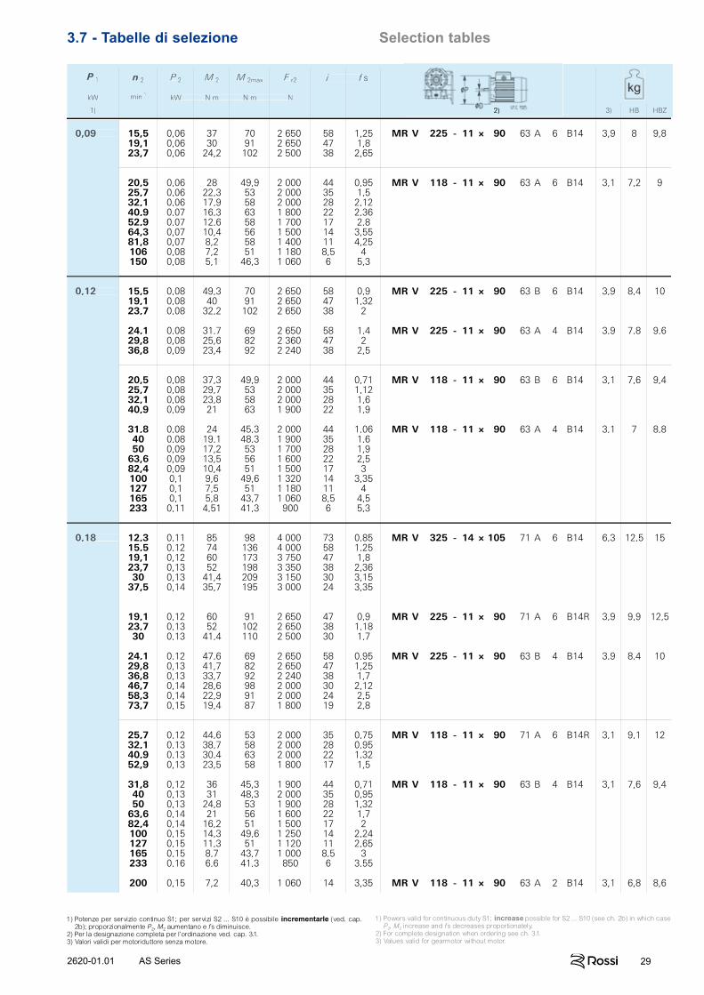
292620-01.01 AS Series
3.7 - Tabelle di selezione Selection tables
n 2 P 2 M 2 M 2max F r2 i f s
min-1kW N m N m N
2) 3) HB HBZ
0,09 15,5 0,06 37 70 2 650 58 1,25 MR V 225 - 11 × 90 63 A 6 B14 3,9 8 9,819,1 0,06 30 91 2 650 47 1,823,7 0,06 24,2 102 2 500 38 2,65
20,5 0,06 28 49,9 2 000 44 0,95 MR V 118 - 11 × 90 63 A 6 B14 3,1 7,2 925,7 0,06 22,3 53 2 000 35 1,532,1 0,06 17,9 58 2 000 28 2,1240,9 0,07 16,3 63 1 800 22 2,3652,9 0,07 12,6 58 1 700 17 2,864,3 0,07 10,4 56 1 500 14 3,5581,8 0,07 8,2 58 1 400 11 4,25106 0,08 7,2 51 1 180 8,5 4150 0,08 5,1 46,3 1 060 6 5,3
0,12 15,5 0,08 49,3 70 2 650 58 0,9 MR V 225 - 11 × 90 63 B 6 B14 3,9 8,4 1019,1 0,08 40 91 2 650 47 1,3223,7 0,08 32,2 102 2 650 38 2
24,1 0,08 31,7 69 2 650 58 1,4 MR V 225 - 11 × 90 63 A 4 B14 3,9 7,8 9,629,8 0,08 25,6 82 2 360 47 236,8 0,09 23,4 92 2 240 38 2,5
20,5 0,08 37,3 49,9 2 000 44 0,71 MR V 118 - 11 × 90 63 B 6 B14 3,1 7,6 9,425,7 0,08 29,7 53 2 000 35 1,1232,1 0,08 23,8 58 2 000 28 1,640,9 0,09 21 63 1 900 22 1,9
31,8 0,08 24 45,3 2 000 44 1,06 MR V 118 - 11 × 90 63 A 4 B14 3,1 7 8,840 0,08 19,1 48,3 1 900 35 1,650 0,09 17,2 53 1 700 28 1,963,6 0,09 13,5 56 1 600 22 2,582,4 0,09 10,4 51 1 500 17 3100 0,1 9,6 49,6 1 320 14 3,35127 0,1 7,5 51 1 180 11 4165 0,1 5,8 43,7 1 060 8,5 4,5233 0,11 4,51 41,3 900 6 5,3
0,18 12,3 0,11 85 98 4 000 73 0,85 MR V 325 - 14 × 105 71 A 6 B14 6,3 12,5 1515,5 0,12 74 136 4 000 58 1,2519,1 0,12 60 173 3 750 47 1,823,7 0,13 52 198 3 350 38 2,3630 0,13 41,4 209 3 150 30 3,1537,5 0,14 35,7 195 3 000 24 3,35
19,1 0,12 60 91 2 650 47 0,9 MR V 225 - 11 × 90 71 A 6 B14R 3,9 9,9 12,523,7 0,13 52 102 2 650 38 1,1830 0,13 41,4 110 2 500 30 1,7
24,1 0,12 47,6 69 2 650 58 0,95 MR V 225 - 11 × 90 63 B 4 B14 3,9 8,4 1029,8 0,13 41,7 82 2 650 47 1,2536,8 0,13 33,7 92 2 240 38 1,746,7 0,14 28,6 98 2 000 30 2,1258,3 0,14 22,9 91 2 000 24 2,573,7 0,15 19,4 87 1 800 19 2,8
25,7 0,12 44,6 53 2 000 35 0,75 MR V 118 - 11 × 90 71 A 6 B14R 3,1 9,1 1232,1 0,13 38,7 58 2 000 28 0,9540,9 0,13 30,4 63 2 000 22 1,3252,9 0,13 23,5 58 1 800 17 1,5
31,8 0,12 36 45,3 1 900 44 0,71 MR V 118 - 11 × 90 63 B 4 B14 3,1 7,6 9,440 0,13 31 48,3 2 000 35 0,9550 0,13 24,8 53 1 900 28 1,3263,6 0,14 21 56 1 600 22 1,782,4 0,14 16,2 51 1 500 17 2100 0,15 14,3 49,6 1 250 14 2,24127 0,15 11,3 51 1 120 11 2,65165 0,15 8,7 43,7 1 000 8,5 3233 0,16 6,6 41,3 850 6 3,55
200 0,15 7,2 40,3 1 060 14 3,35 MR V 118 - 11 × 90 63 A 2 B14 3,1 6,8 8,6
P 1
kW
1)
n 2 P 2 M 2 M 2max F r2 i f s
min-1kW N m N m N
2) 3) HB HBZ
P 1
kW
1) 2) 3) HB HBZ
0,09 15
0,12 15
0,18 12
1) Potenze per servizio continuo S1; per servizi S2 ... S10 è possibile incrementarle (ved. cap. 2b); proporzionalmente P2, M2 aumentano e fs diminuisce.
2) Per la designazione completa per l’ordinazione ved. cap. 3.1.3) Valori validi per motoriduttore senza motore.
1) Powers valid for continuous duty S1; increase possible for S2 ... S10 (see ch. 2b) in which case P2, M2 increase and fs decreases proportionately.
2) For complete designation when ordering see ch. 3.1.3) Values valid for gearmotor without motor.
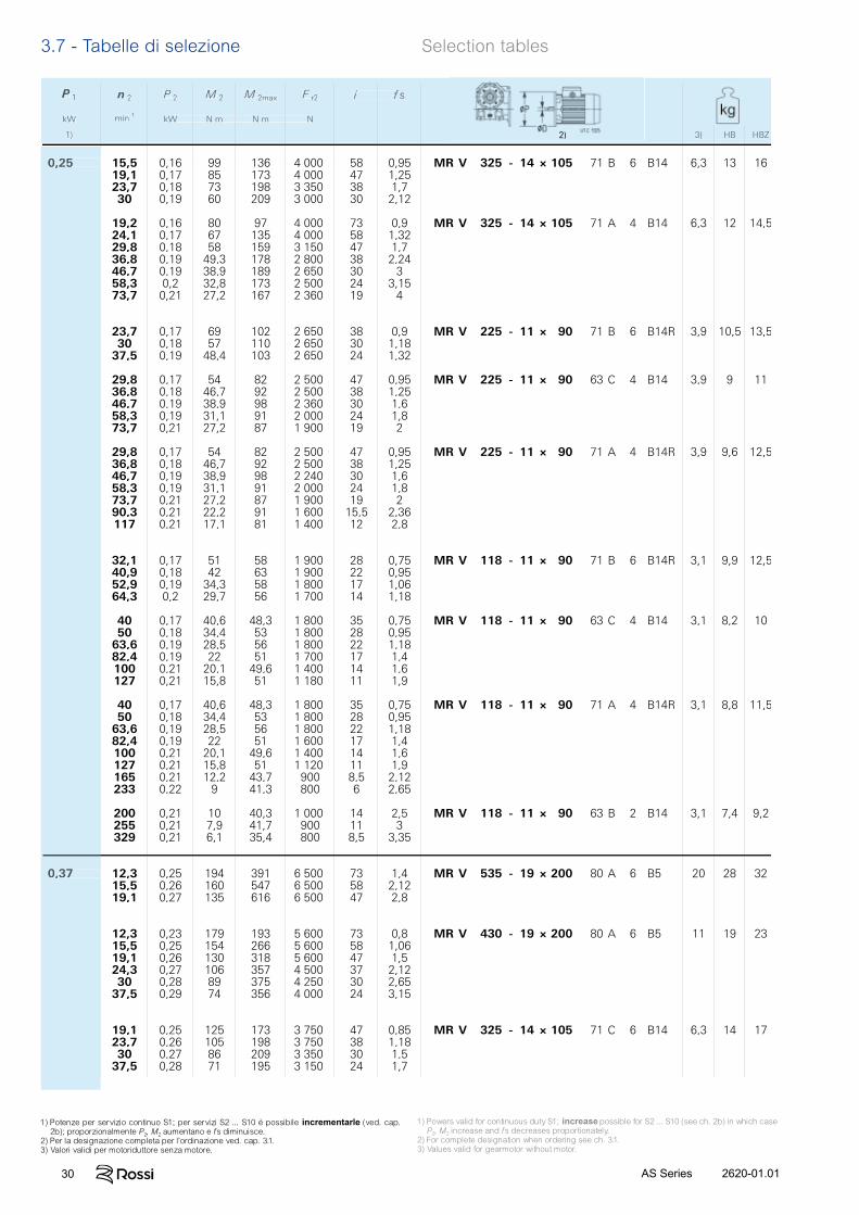
30 2620-01.01AS Series
3.7 - Tabelle di selezione Selection tables
n 2 P 2 M 2 M 2max F r2 i f s
min-1kW N m N m N
2) 3) HB HBZ
P 1
kW
1)
0,25 15,5 0,16 99 136 4 000 58 0,95 MR V 325 - 14 × 105 71 B 6 B14 6,3 13 1619,1 0,17 85 173 4 000 47 1,2523,7 0,18 73 198 3 350 38 1,730 0,19 60 209 3 000 30 2,12
19,2 0,16 80 97 4 000 73 0,9 MR V 325 - 14 × 105 71 A 4 B14 6,3 12 14,524,1 0,17 67 135 4 000 58 1,3229,8 0,18 58 159 3 150 47 1,736,8 0,19 49,3 178 2 800 38 2,2446,7 0,19 38,9 189 2 650 30 358,3 0,2 32,8 173 2 500 24 3,1573,7 0,21 27,2 167 2 360 19 4
23,7 0,17 69 102 2 650 38 0,9 MR V 225 - 11 × 90 71 B 6 B14R 3,9 10,5 13,530 0,18 57 110 2 650 30 1,1837,5 0,19 48,4 103 2 650 24 1,32
29,8 0,17 54 82 2 500 47 0,95 MR V 225 - 11 × 90 63 C 4 B14 3,9 9 1136,8 0,18 46,7 92 2 500 38 1,2546,7 0,19 38,9 98 2 360 30 1,658,3 0,19 31,1 91 2 000 24 1,873,7 0,21 27,2 87 1 900 19 2
29,8 0,17 54 82 2 500 47 0,95 MR V 225 - 11 × 90 71 A 4 B14R 3,9 9,6 12,536,8 0,18 46,7 92 2 500 38 1,2546,7 0,19 38,9 98 2 240 30 1,658,3 0,19 31,1 91 2 000 24 1,873,7 0,21 27,2 87 1 900 19 290,3 0,21 22,2 91 1 600 15,5 2,36117 0,21 17,1 81 1 400 12 2,8
32,1 0,17 51 58 1 900 28 0,75 MR V 118 - 11 × 90 71 B 6 B14R 3,1 9,9 12,540,9 0,18 42 63 1 900 22 0,9552,9 0,19 34,3 58 1 800 17 1,0664,3 0,2 29,7 56 1 700 14 1,18
40 0,17 40,6 48,3 1 800 35 0,75 MR V 118 - 11 × 90 63 C 4 B14 3,1 8,2 1050 0,18 34,4 53 1 800 28 0,9563,6 0,19 28,5 56 1 800 22 1,1882,4 0,19 22 51 1 700 17 1,4100 0,21 20,1 49,6 1 400 14 1,6127 0,21 15,8 51 1 180 11 1,9
40 0,17 40,6 48,3 1 800 35 0,75 MR V 118 - 11 × 90 71 A 4 B14R 3,1 8,8 11,550 0,18 34,4 53 1 800 28 0,9563,6 0,19 28,5 56 1 800 22 1,1882,4 0,19 22 51 1 600 17 1,4100 0,21 20,1 49,6 1 400 14 1,6127 0,21 15,8 51 1 120 11 1,9165 0,21 12,2 43,7 900 8,5 2,12233 0,22 9 41,3 800 6 2,65
200 0,21 10 40,3 1 000 14 2,5 MR V 118 - 11 × 90 63 B 2 B14 3,1 7,4 9,2255 0,21 7,9 41,7 900 11 3329 0,21 6,1 35,4 800 8,5 3,35
0,37 12,3 0,25 194 391 6 500 73 1,4 MR V 535 - 19 × 200 80 A 6 B5 20 28 3215,5 0,26 160 547 6 500 58 2,1219,1 0,27 135 616 6 500 47 2,8
12,3 0,23 179 193 5 600 73 0,8 MR V 430 - 19 × 200 80 A 6 B5 11 19 2315,5 0,25 154 266 5 600 58 1,0619,1 0,26 130 318 5 600 47 1,524,3 0,27 106 357 4 500 37 2,1230 0,28 89 375 4 250 30 2,6537,5 0,29 74 356 4 000 24 3,15
19,1 0,25 125 173 3 750 47 0,85 MR V 325 - 14 × 105 71 C 6 B14 6,3 14 1723,7 0,26 105 198 3 750 38 1,1830 0,27 86 209 3 350 30 1,537,5 0,28 71 195 3 150 24 1,7
n 2 P 2 M 2 M 2max F r2 i f s
min-1kW N m N m N
3) HB HBZ
P 1
kW
1) 2)
0,25 15
0,37 12
1) Potenze per servizio continuo S1; per servizi S2 ... S10 è possibile incrementarle (ved. cap. 2b); proporzionalmente P2, M2 aumentano e fs diminuisce.
2) Per la designazione completa per l’ordinazione ved. cap. 3.1.3) Valori validi per motoriduttore senza motore.
1) Powers valid for continuous duty S1; increase possible for S2 ... S10 (see ch. 2b) in which case P2, M2 increase and fs decreases proportionately.
2) For complete designation when ordering see ch. 3.1.3) Values valid for gearmotor without motor.
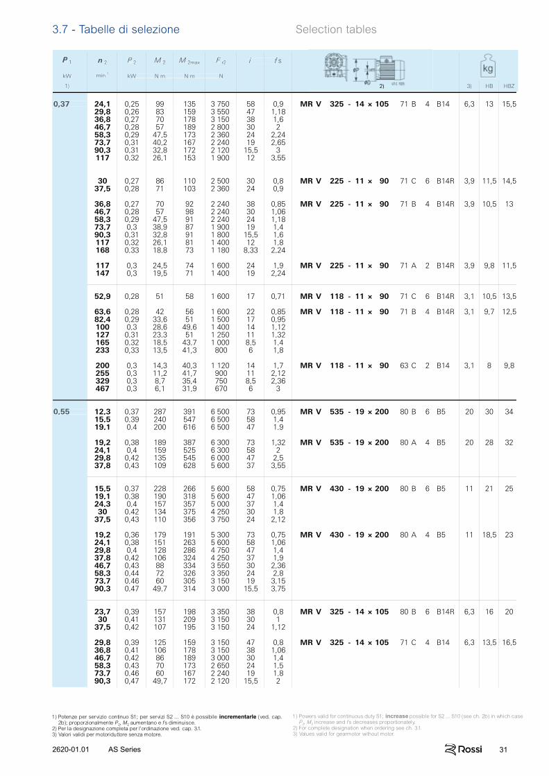
312620-01.01 AS Series
3.7 - Tabelle di selezione Selection tables
n 2 P 2 M 2 M 2max F r2 i f s
min-1kW N m N m N
2) 3) HB HBZ
P 1
kW
1)
0,37 24,1 0,25 99 135 3 750 58 0,9 MR V 325 - 14 × 105 71 B 4 B14 6,3 13 15,529,8 0,26 83 159 3 550 47 1,1836,8 0,27 70 178 3 150 38 1,646,7 0,28 57 189 2 800 30 258,3 0,29 47,5 173 2 360 24 2,2473,7 0,31 40,2 167 2 240 19 2,6590,3 0,31 32,8 172 2 120 15,5 3117 0,32 26,1 153 1 900 12 3,55
30 0,27 86 110 2 500 30 0,8 MR V 225 - 11 × 90 71 C 6 B14R 3,9 11,5 14,537,5 0,28 71 103 2 360 24 0,9
36,8 0,27 70 92 2 240 38 0,85 MR V 225 - 11 × 90 71 B 4 B14R 3,9 10,5 1346,7 0,28 57 98 2 240 30 1,0658,3 0,29 47,5 91 2 240 24 1,1873,7 0,3 38,9 87 1 900 19 1,490,3 0,31 32,8 91 1 800 15,5 1,6117 0,32 26,1 81 1 400 12 1,8168 0,33 18,8 73 1 180 8,33 2,24
117 0,3 24,5 74 1 600 24 1,9 MR V 225 - 11 × 90 71 A 2 B14R 3,9 9,8 11,5147 0,3 19,5 71 1 400 19 2,24
52,9 0,28 51 58 1 600 17 0,71 MR V 118 - 11 × 90 71 C 6 B14R 3,1 10,5 13,5
63,6 0,28 42 56 1 600 22 0,85 MR V 118 - 11 × 90 71 B 4 B14R 3,1 9,7 12,582,4 0,29 33,6 51 1 500 17 0,95100 0,3 28,6 49,6 1 400 14 1,12127 0,31 23,3 51 1 250 11 1,32165 0,32 18,5 43,7 1 000 8,5 1,4233 0,33 13,5 41,3 800 6 1,8
200 0,3 14,3 40,3 1 120 14 1,7 MR V 118 - 11 × 90 63 C 2 B14 3,1 8 9,8255 0,3 11,2 41,7 900 11 2,12329 0,3 8,7 35,4 750 8,5 2,36467 0,3 6,1 31,9 670 6 3
0,55 12,3 0,37 287 391 6 500 73 0,95 MR V 535 - 19 × 200 80 B 6 B5 20 30 3415,5 0,39 240 547 6 500 58 1,419,1 0,4 200 616 6 500 47 1,9
19,2 0,38 189 387 6 300 73 1,32 MR V 535 - 19 × 200 80 A 4 B5 20 28 3224,1 0,4 159 525 6 300 58 229,8 0,42 135 545 6 000 47 2,537,8 0,43 109 628 5 600 37 3,55
15,5 0,37 228 266 5 600 58 0,75 MR V 430 - 19 × 200 80 B 6 B5 11 21 2519,1 0,38 190 318 5 600 47 1,0624,3 0,4 157 357 5 000 37 1,430 0,42 134 375 4 250 30 1,837,5 0,43 110 356 3 750 24 2,12
19,2 0,36 179 191 5 300 73 0,75 MR V 430 - 19 × 200 80 A 4 B5 11 18,5 2324,1 0,38 151 263 5 600 58 1,0629,8 0,4 128 286 4 750 47 1,437,8 0,42 106 324 4 250 37 1,946,7 0,43 88 334 3 550 30 2,3658,3 0,44 72 326 3 350 24 2,873,7 0,46 60 305 3 150 19 3,1590,3 0,47 49,7 314 3 000 15,5 3,75
23,7 0,39 157 198 3 350 38 0,8 MR V 325 - 14 × 105 80 B 6 B14R 6,3 16 2030 0,41 131 209 3 150 30 137,5 0,42 107 195 3 150 24 1,12
29,8 0,39 125 159 3 150 47 0,8 MR V 325 - 14 × 105 71 C 4 B14 6,3 13,5 16,536,8 0,41 106 178 3 150 38 1,0646,7 0,42 86 189 3 000 30 1,458,3 0,43 70 173 2 650 24 1,573,7 0,46 60 167 2 240 19 1,890,3 0,47 49,7 172 2 120 15,5 2
n 2 P 2 M 2 M 2max F r2 i f s
min-1kW N m N m N
3) HB HBZ
P 1
kW
1) 2)
0,37 24
0,55 12
1) Potenze per servizio continuo S1; per servizi S2 ... S10 è possibile incrementarle (ved. cap. 2b); proporzionalmente P2, M2 aumentano e fs diminuisce.
2) Per la designazione completa per l’ordinazione ved. cap. 3.1.3) Valori validi per motoriduttore senza motore.
1) Powers valid for continuous duty S1; increase possible for S2 ... S10 (see ch. 2b) in which case P2, M2 increase and fs decreases proportionately.
2) For complete designation when ordering see ch. 3.1.3) Values valid for gearmotor without motor.
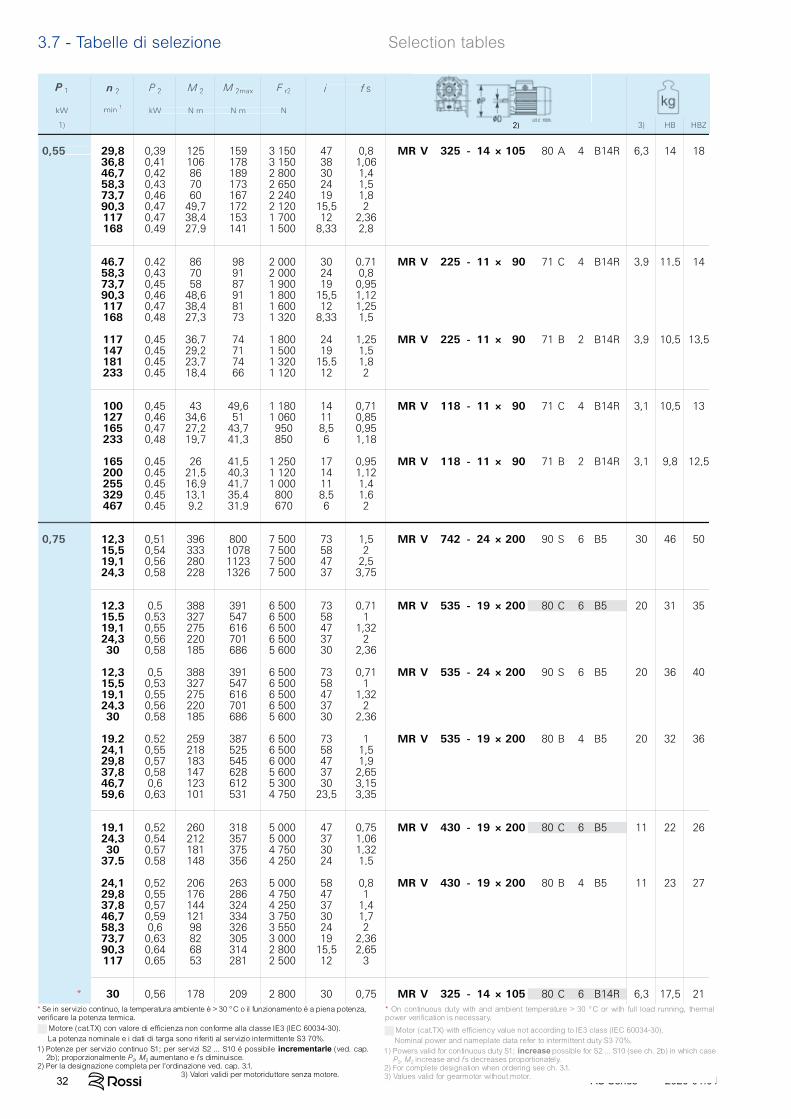
32 2620-01.01AS Series
3.7 - Tabelle di selezione Selection tables
n 2 P 2 M 2 M 2max F r2 i f s
min-1kW N m N m N
2) 3) HB HBZ
P 1
kW
1)
0,55 29,8 0,39 125 159 3 150 47 0,8 MR V 325 - 14 × 105 80 A 4 B14R 6,3 14 1836,8 0,41 106 178 3 150 38 1,0646,7 0,42 86 189 2 800 30 1,458,3 0,43 70 173 2 650 24 1,573,7 0,46 60 167 2 240 19 1,890,3 0,47 49,7 172 2 120 15,5 2117 0,47 38,4 153 1 700 12 2,36168 0,49 27,9 141 1 500 8,33 2,8
46,7 0,42 86 98 2 000 30 0,71 MR V 225 - 11 × 90 71 C 4 B14R 3,9 11,5 1458,3 0,43 70 91 2 000 24 0,873,7 0,45 58 87 1 900 19 0,9590,3 0,46 48,6 91 1 800 15,5 1,12117 0,47 38,4 81 1 600 12 1,25168 0,48 27,3 73 1 320 8,33 1,5
117 0,45 36,7 74 1 800 24 1,25 MR V 225 - 11 × 90 71 B 2 B14R 3,9 10,5 13,5147 0,45 29,2 71 1 500 19 1,5181 0,45 23,7 74 1 320 15,5 1,8233 0,45 18,4 66 1 120 12 2
100 0,45 43 49,6 1 180 14 0,71 MR V 118 - 11 × 90 71 C 4 B14R 3,1 10,5 13127 0,46 34,6 51 1 060 11 0,85165 0,47 27,2 43,7 950 8,5 0,95233 0,48 19,7 41,3 850 6 1,18
165 0,45 26 41,5 1 250 17 0,95 MR V 118 - 11 × 90 71 B 2 B14R 3,1 9,8 12,5200 0,45 21,5 40,3 1 120 14 1,12255 0,45 16,9 41,7 1 000 11 1,4329 0,45 13,1 35,4 800 8,5 1,6467 0,45 9,2 31,9 670 6 2
0,75 12,3 0,51 396 800 7 500 73 1,5 MR V 742 - 24 × 200 90 S 6 B5 30 46 5015,5 0,54 333 1078 7 500 58 219,1 0,56 280 1123 7 500 47 2,524,3 0,58 228 1326 7 500 37 3,75
12,3 0,5 388 391 6 500 73 0,71 MR V 535 - 19 × 200 80 C 6 B5 20 31 3515,5 0,53 327 547 6 500 58 119,1 0,55 275 616 6 500 47 1,3224,3 0,56 220 701 6 500 37 230 0,58 185 686 5 600 30 2,36
12,3 0,5 388 391 6 500 73 0,71 MR V 535 - 24 × 200 90 S 6 B5 20 36 4015,5 0,53 327 547 6 500 58 119,1 0,55 275 616 6 500 47 1,3224,3 0,56 220 701 6 500 37 230 0,58 185 686 5 600 30 2,36
19,2 0,52 259 387 6 500 73 1 MR V 535 - 19 × 200 80 B 4 B5 20 32 3624,1 0,55 218 525 6 500 58 1,529,8 0,57 183 545 6 000 47 1,937,8 0,58 147 628 5 600 37 2,6546,7 0,6 123 612 5 300 30 3,1559,6 0,63 101 531 4 750 23,5 3,35
19,1 0,52 260 318 5 000 47 0,75 MR V 430 - 19 × 200 80 C 6 B5 11 22 2624,3 0,54 212 357 5 000 37 1,0630 0,57 181 375 4 750 30 1,3237,5 0,58 148 356 4 250 24 1,5
24,1 0,52 206 263 5 000 58 0,8 MR V 430 - 19 × 200 80 B 4 B5 11 23 2729,8 0,55 176 286 4 750 47 137,8 0,57 144 324 4 250 37 1,446,7 0,59 121 334 3 750 30 1,758,3 0,6 98 326 3 550 24 273,7 0,63 82 305 3 000 19 2,3690,3 0,64 68 314 2 800 15,5 2,65117 0,65 53 281 2 500 12 3
* 30 0,56 178 209 2 800 30 0,75 MR V 325 - 14 × 105 80 C 6 B14R 6,3 17,5 21
n 2 P 2 M 2 M 2max F r2 i f s
min-1kW N m N m N
2) 3) HB HBZ
P 1
kW
1) 2) 3) HB HBZ
0,55 29
0,75 12
*
Motore (cat.TX) con valore di efficienza non conforme alla classe IE3 (IEC 60034-30). La potenza nominale e i dati di targa sono riferiti al servizio intermittente S3 70%.1) Potenze per servizio continuo S1; per servizi S2 ... S10 è possibile incrementarle (ved. cap.
2b); proporzionalmente P2, M2 aumentano e fs diminuisce.2) Per la designazione completa per l’ordinazione ved. cap. 3.1. 3) Valori validi per motoriduttore senza motore.
Motor (cat.TX) with efficiency value not according to IE3 class (IEC 60034-30). Nominal power and nameplate data refer to intermittent duty S3 70%.1) Powers valid for continuous duty S1; increase possible for S2 ... S10 (see ch. 2b) in which case
P2, M2 increase and fs decreases proportionately.2) For complete designation when ordering see ch. 3.1.3) Values valid for gearmotor without motor.
* On continuous duty with and ambient temperature > 30 °C or with full load running, thermal power verification is necessary.
* Se in servizio continuo, la temperatura ambiente è > 30 °C o il funzionamento è a piena potenza, verificare la potenza termica.
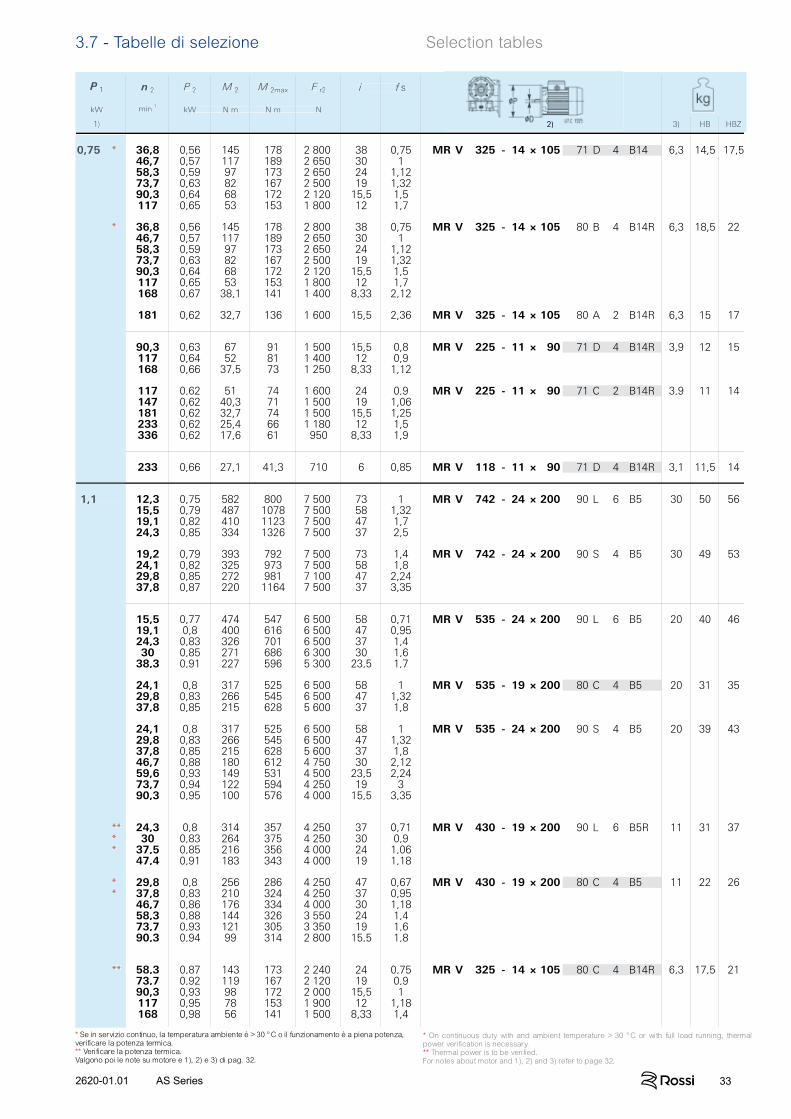
332620-01.01 AS Series
n 2 P 2 M 2 M 2max F r2 i f s
min-1kW N m N m N
2) 3) HB HBZ
P 1
kW
1)
0,75 * 36,8 0,56 145 178 2 800 38 0,75 MR V 325 - 14 × 105 71 D 4 B14 6,3 14,5 17,546,7 0,57 117 189 2 650 30 158,3 0,59 97 173 2 650 24 1,1273,7 0,63 82 167 2 500 19 1,3290,3 0,64 68 172 2 120 15,5 1,5117 0,65 53 153 1 800 12 1,7
* 36,8 0,56 145 178 2 800 38 0,75 MR V 325 - 14 × 105 80 B 4 B14R 6,3 18,5 2246,7 0,57 117 189 2 650 30 158,3 0,59 97 173 2 650 24 1,1273,7 0,63 82 167 2 500 19 1,3290,3 0,64 68 172 2 120 15,5 1,5117 0,65 53 153 1 800 12 1,7168 0,67 38,1 141 1 400 8,33 2,12
181 0,62 32,7 136 1 600 15,5 2,36 MR V 325 - 14 × 105 80 A 2 B14R 6,3 15 17
90,3 0,63 67 91 1 500 15,5 0,8 MR V 225 - 11 × 90 71 D 4 B14R 3,9 12 15117 0,64 52 81 1 400 12 0,9168 0,66 37,5 73 1 250 8,33 1,12
117 0,62 51 74 1 600 24 0,9 MR V 225 - 11 × 90 71 C 2 B14R 3,9 11 14147 0,62 40,3 71 1 500 19 1,06181 0,62 32,7 74 1 500 15,5 1,25233 0,62 25,4 66 1 180 12 1,5336 0,62 17,6 61 950 8,33 1,9
233 0,66 27,1 41,3 710 6 0,85 MR V 118 - 11 × 90 71 D 4 B14R 3,1 11,5 14
1,1 12,3 0,75 582 800 7 500 73 1 MR V 742 - 24 × 200 90 L 6 B5 30 50 5615,5 0,79 487 1078 7 500 58 1,3219,1 0,82 410 1123 7 500 47 1,724,3 0,85 334 1326 7 500 37 2,5
19,2 0,79 393 792 7 500 73 1,4 MR V 742 - 24 × 200 90 S 4 B5 30 49 5324,1 0,82 325 973 7 500 58 1,829,8 0,85 272 981 7 100 47 2,2437,8 0,87 220 1164 7 500 37 3,35
15,5 0,77 474 547 6 500 58 0,71 MR V 535 - 24 × 200 90 L 6 B5 20 40 4619,1 0,8 400 616 6 500 47 0,9524,3 0,83 326 701 6 500 37 1,430 0,85 271 686 6 300 30 1,638,3 0,91 227 596 5 300 23,5 1,7
24,1 0,8 317 525 6 500 58 1 MR V 535 - 19 × 200 80 C 4 B5 20 31 3529,8 0,83 266 545 6 500 47 1,3237,8 0,85 215 628 5 600 37 1,8
24,1 0,8 317 525 6 500 58 1 MR V 535 - 24 × 200 90 S 4 B5 20 39 4329,8 0,83 266 545 6 500 47 1,3237,8 0,85 215 628 5 600 37 1,846,7 0,88 180 612 4 750 30 2,1259,6 0,93 149 531 4 500 23,5 2,2473,7 0,94 122 594 4 250 19 390,3 0,95 100 576 4 000 15,5 3,35
** 24,3 0,8 314 357 4 250 37 0,71 MR V 430 - 19 × 200 90 L 6 B5R 11 31 37* 30 0,83 264 375 4 250 30 0,9* 37,5 0,85 216 356 4 000 24 1,06
47,4 0,91 183 343 4 000 19 1,18
* 29,8 0,8 256 286 4 250 47 0,67 MR V 430 - 19 × 200 80 C 4 B5 11 22 26* 37,8 0,83 210 324 4 250 37 0,95
46,7 0,86 176 334 4 000 30 1,1858,3 0,88 144 326 3 550 24 1,473,7 0,93 121 305 3 350 19 1,690,3 0,94 99 314 2 800 15,5 1,8
** 58,3 0,87 143 173 2 240 24 0,75 MR V 325 - 14 × 105 80 C 4 B14R 6,3 17,5 2173,7 0,92 119 167 2 120 19 0,990,3 0,93 98 172 2 000 15,5 1117 0,95 78 153 1 900 12 1,18168 0,98 56 141 1 500 8,33 1,4
n 2 P 2 M 2 M 2max F r2 i f s
min-1kW N m N m N
2) 3) HB HBZ
P 1
kW
1) 2) 3) HB HBZ
0,75 *
*
1,1 12
****
**
**
* On continuous duty with and ambient temperature > 30 °C or with full load running, thermal power verification is necessary.** Thermal power is to be verified.For notes about motor and 1), 2) and 3) refer to page 32.
* Se in servizio continuo, la temperatura ambiente è > 30 °C o il funzionamento è a piena potenza, verificare la potenza termica.** Verificare la potenza termica.Valgono poi le note su motore e 1), 2) e 3) di pag. 32.
3.7 - Tabelle di selezione Selection tables
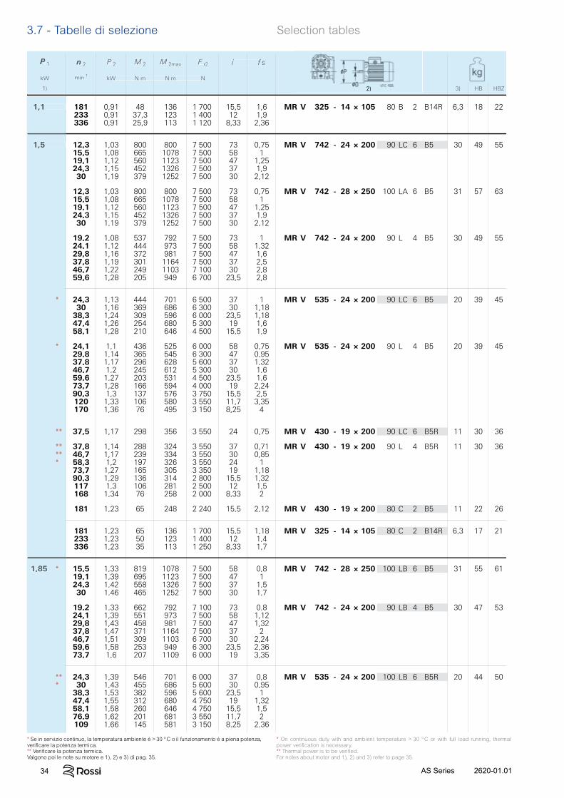
34 2620-01.01AS Series
n 2 P 2 M 2 M 2max F r2 i f s
min-1kW N m N m N
2) 3) HB HBZ
P 1
kW
1)
1,1 181 0,91 48 136 1 700 15,5 1,6 MR V 325 - 14 × 105 80 B 2 B14R 6,3 18 22233 0,91 37,3 123 1 400 12 1,9336 0,91 25,9 113 1 120 8,33 2,36
1,5 12,3 1,03 800 800 7 500 73 0,75 MR V 742 - 24 × 200 90 LC 6 B5 30 49 5515,5 1,08 665 1078 7 500 58 119,1 1,12 560 1123 7 500 47 1,2524,3 1,15 452 1326 7 500 37 1,930 1,19 379 1252 7 500 30 2,12
12,3 1,03 800 800 7 500 73 0,75 MR V 742 - 28 × 250 100 LA 6 B5 31 57 6315,5 1,08 665 1078 7 500 58 119,1 1,12 560 1123 7 500 47 1,2524,3 1,15 452 1326 7 500 37 1,930 1,19 379 1252 7 500 30 2,12
19,2 1,08 537 792 7 500 73 1 MR V 742 - 24 × 200 90 L 4 B5 30 49 5524,1 1,12 444 973 7 500 58 1,3229,8 1,16 372 981 7 500 47 1,637,8 1,19 301 1164 7 500 37 2,546,7 1,22 249 1103 7 100 30 2,859,6 1,28 205 949 6 700 23,5 2,8
* 24,3 1,13 444 701 6 500 37 1 MR V 535 - 24 × 200 90 LC 6 B5 20 39 4530 1,16 369 686 6 300 30 1,1838,3 1,24 309 596 6 000 23,5 1,1847,4 1,26 254 680 5 300 19 1,658,1 1,28 210 646 4 500 15,5 1,9
* 24,1 1,1 436 525 6 000 58 0,75 MR V 535 - 24 × 200 90 L 4 B5 20 39 4529,8 1,14 365 545 6 300 47 0,9537,8 1,17 296 628 5 600 37 1,3246,7 1,2 245 612 5 300 30 1,659,6 1,27 203 531 4 500 23,5 1,673,7 1,28 166 594 4 000 19 2,2490,3 1,3 137 576 3 750 15,5 2,5120 1,33 106 580 3 550 11,7 3,35170 1,36 76 495 3 150 8,25 4
** 37,5 1,17 298 356 3 550 24 0,75 MR V 430 - 19 × 200 90 LC 6 B5R 11 30 36
** 37,8 1,14 288 324 3 550 37 0,71 MR V 430 - 19 × 200 90 L 4 B5R 11 30 36** 46,7 1,17 239 334 3 550 30 0,85* 58,3 1,2 197 326 3 550 24 1
73,7 1,27 165 305 3 350 19 1,1890,3 1,29 136 314 2 800 15,5 1,32117 1,3 106 281 2 500 12 1,5168 1,34 76 258 2 000 8,33 2
181 1,23 65 248 2 240 15,5 2,12 MR V 430 - 19 × 200 80 C 2 B5 11 22 26
181 1,23 65 136 1 700 15,5 1,18 MR V 325 - 14 × 105 80 C 2 B14R 6,3 17 21233 1,23 50 123 1 400 12 1,4336 1,23 35 113 1 250 8,33 1,7
1,85 * 15,5 1,33 819 1078 7 500 58 0,8 MR V 742 - 28 × 250 100 LB 6 B5 31 55 6119,1 1,39 695 1123 7 500 47 124,3 1,42 558 1326 7 500 37 1,530 1,46 465 1252 7 500 30 1,7
19,2 1,33 662 792 7 100 73 0,8 MR V 742 - 24 × 200 90 LB 4 B5 30 47 5324,1 1,39 551 973 7 500 58 1,1229,8 1,43 458 981 7 500 47 1,3237,8 1,47 371 1164 7 500 37 246,7 1,51 309 1103 6 700 30 2,2459,6 1,58 253 949 6 300 23,5 2,3673,7 1,6 207 1109 6 000 19 3,35
** 24,3 1,39 546 701 6 000 37 0,8 MR V 535 - 24 × 200 100 LB 6 B5R 20 44 50* 30 1,43 455 686 5 600 30 0,95
38,3 1,53 382 596 5 600 23,5 147,4 1,55 312 680 4 750 19 1,3258,1 1,58 260 646 4 750 15,5 1,576,9 1,62 201 681 3 550 11,7 2109 1,66 145 581 3 150 8,25 2,36
n 2 P 2 M 2 M 2max F r2 i f s
min-1kW N m N m N
2) 3) HB HBZ
P 1
kW
1) 2) 3) HB HBZ
1,1 181
1,5 12
*
*
**
*****
1,85 *
***
* On continuous duty with and ambient temperature > 30 °C or with full load running, thermal power verification is necessary.** Thermal power is to be verified.For notes about motor and 1), 2) and 3) refer to page 35.
* Se in servizio continuo, la temperatura ambiente è > 30 °C o il funzionamento è a piena potenza, verificare la potenza termica.** Verificare la potenza termica.Valgono poi le note su motore e 1), 2) e 3) di pag. 35.
3.7 - Tabelle di selezione Selection tables
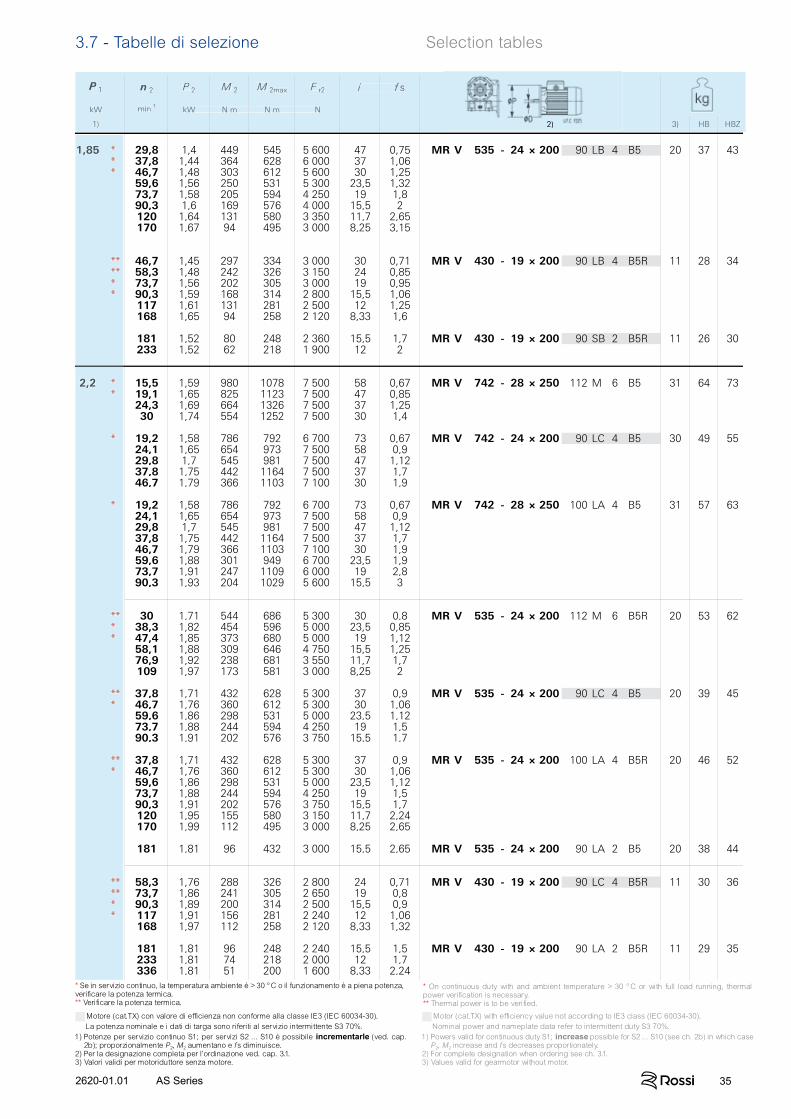
352620-01.01 AS Series
n 2 P 2 M 2 M 2max F r2 i f s
min-1kW N m N m N
2) 3) HB HBZ
P 1
kW
1)
1,85 * 29,8 1,4 449 545 5 600 47 0,75 MR V 535 - 24 × 200 90 LB 4 B5 20 37 43* 37,8 1,44 364 628 6 000 37 1,06* 46,7 1,48 303 612 5 600 30 1,25
59,6 1,56 250 531 5 300 23,5 1,3273,7 1,58 205 594 4 250 19 1,890,3 1,6 169 576 4 000 15,5 2120 1,64 131 580 3 350 11,7 2,65170 1,67 94 495 3 000 8,25 3,15
** 46,7 1,45 297 334 3 000 30 0,71 MR V 430 - 19 × 200 90 LB 4 B5R 11 28 34** 58,3 1,48 242 326 3 150 24 0,85* 73,7 1,56 202 305 3 000 19 0,95* 90,3 1,59 168 314 2 800 15,5 1,06
117 1,61 131 281 2 500 12 1,25168 1,65 94 258 2 120 8,33 1,6
181 1,52 80 248 2 360 15,5 1,7 MR V 430 - 19 × 200 90 SB 2 B5R 11 26 30233 1,52 62 218 1 900 12 2
2,2 * 15,5 1,59 980 1078 7 500 58 0,67 MR V 742 - 28 × 250 112 M 6 B5 31 64 73* 19,1 1,65 825 1123 7 500 47 0,85
24,3 1,69 664 1326 7 500 37 1,2530 1,74 554 1252 7 500 30 1,4
* 19,2 1,58 786 792 6 700 73 0,67 MR V 742 - 24 × 200 90 LC 4 B5 30 49 5524,1 1,65 654 973 7 500 58 0,929,8 1,7 545 981 7 500 47 1,1237,8 1,75 442 1164 7 500 37 1,746,7 1,79 366 1103 7 100 30 1,9
* 19,2 1,58 786 792 6 700 73 0,67 MR V 742 - 28 × 250 100 LA 4 B5 31 57 6324,1 1,65 654 973 7 500 58 0,929,8 1,7 545 981 7 500 47 1,1237,8 1,75 442 1164 7 500 37 1,746,7 1,79 366 1103 7 100 30 1,959,6 1,88 301 949 6 700 23,5 1,973,7 1,91 247 1109 6 000 19 2,890,3 1,93 204 1029 5 600 15,5 3
** 30 1,71 544 686 5 300 30 0,8 MR V 535 - 24 × 200 112 M 6 B5R 20 53 62* 38,3 1,82 454 596 5 000 23,5 0,85* 47,4 1,85 373 680 5 000 19 1,12
58,1 1,88 309 646 4 750 15,5 1,2576,9 1,92 238 681 3 550 11,7 1,7109 1,97 173 581 3 000 8,25 2
** 37,8 1,71 432 628 5 300 37 0,9 MR V 535 - 24 × 200 90 LC 4 B5 20 39 45* 46,7 1,76 360 612 5 300 30 1,06
59,6 1,86 298 531 5 000 23,5 1,1273,7 1,88 244 594 4 250 19 1,590,3 1,91 202 576 3 750 15,5 1,7
** 37,8 1,71 432 628 5 300 37 0,9 MR V 535 - 24 × 200 100 LA 4 B5R 20 46 52* 46,7 1,76 360 612 5 300 30 1,06
59,6 1,86 298 531 5 000 23,5 1,1273,7 1,88 244 594 4 250 19 1,590,3 1,91 202 576 3 750 15,5 1,7120 1,95 155 580 3 150 11,7 2,24170 1,99 112 495 3 000 8,25 2,65
181 1,81 96 432 3 000 15,5 2,65 MR V 535 - 24 × 200 90 LA 2 B5 20 38 44
** 58,3 1,76 288 326 2 800 24 0,71 MR V 430 - 19 × 200 90 LC 4 B5R 11 30 36** 73,7 1,86 241 305 2 650 19 0,8* 90,3 1,89 200 314 2 500 15,5 0,9* 117 1,91 156 281 2 240 12 1,06
168 1,97 112 258 2 120 8,33 1,32
181 1,81 96 248 2 240 15,5 1,5 MR V 430 - 19 × 200 90 LA 2 B5R 11 29 35233 1,81 74 218 2 000 12 1,7336 1,81 51 200 1 600 8,33 2,24
n 2 P 2 M 2 M 2max F r2 i f s
min-1kW N m N m N
2) 3) HB HBZ
P 1
kW
1) 2) 3) HB HBZ
1,85 ***
******
2,2 **
*
*
****
***
***
******
Motore (cat.TX) con valore di efficienza non conforme alla classe IE3 (IEC 60034-30). La potenza nominale e i dati di targa sono riferiti al servizio intermittente S3 70%.1) Potenze per servizio continuo S1; per servizi S2 ... S10 è possibile incrementarle (ved. cap.
2b); proporzionalmente P2, M2 aumentano e fs diminuisce.2) Per la designazione completa per l’ordinazione ved. cap. 3.1.3) Valori validi per motoriduttore senza motore.
Motor (cat.TX) with efficiency value not according to IE3 class (IEC 60034-30). Nominal power and nameplate data refer to intermittent duty S3 70%.1) Powers valid for continuous duty S1; increase possible for S2 ... S10 (see ch. 2b) in which case
P2, M2 increase and fs decreases proportionately.2) For complete designation when ordering see ch. 3.1.3) Values valid for gearmotor without motor.
* On continuous duty with and ambient temperature > 30 °C or with full load running, thermal power verification is necessary.** Thermal power is to be verified.
* Se in servizio continuo, la temperatura ambiente è > 30 °C o il funzionamento è a piena potenza, verificare la potenza termica.** Verificare la potenza termica.
3.7 - Tabelle di selezione Selection tables
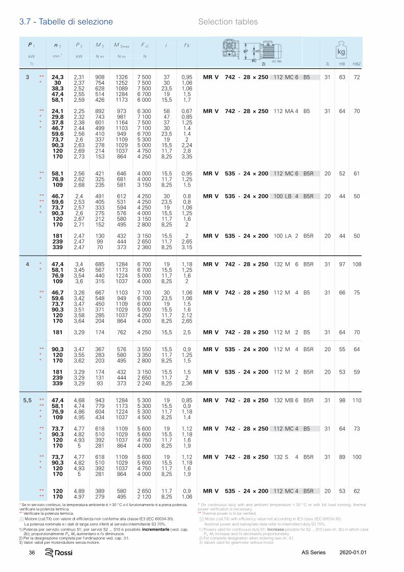
36 2620-01.01AS Series
n 2 P 2 M 2 M 2max F r2 i f s
min-1kW N m N m N
2) 3) HB HBZ
P 1
kW
1)
3 ** 24,3 2,31 908 1326 7 500 37 0,95 MR V 742 - 28 × 250 112 MC 6 B5 31 63 72* 30 2,37 754 1252 7 500 30 1,06
38,3 2,52 628 1089 7 500 23,5 1,0647,4 2,55 514 1284 6 700 19 1,558,1 2,59 426 1173 6 000 15,5 1,7
** 24,1 2,25 892 973 6 300 58 0,67 MR V 742 - 28 × 250 112 MA 4 B5 31 64 70* 29,8 2,32 743 981 7 100 47 0,85* 37,8 2,38 601 1164 7 500 37 1,25* 46,7 2,44 499 1103 7 100 30 1,4
59,6 2,56 410 949 6 700 23,5 1,473,7 2,6 337 1109 5 300 19 290,3 2,63 278 1029 5 000 15,5 2,24120 2,69 214 1037 4 750 11,7 2,8170 2,73 153 864 4 250 8,25 3,35
** 58,1 2,56 421 646 4 000 15,5 0,95 MR V 535 - 24 × 200 112 MC 6 B5R 20 52 61* 76,9 2,62 325 681 4 000 11,7 1,25
109 2,68 235 581 3 150 8,25 1,5
** 46,7 2,4 491 612 4 250 30 0,8 MR V 535 - 24 × 200 100 LB 4 B5R 20 44 50** 59,6 2,53 405 531 4 250 23,5 0,8* 73,7 2,57 333 594 4 250 19 1,06* 90,3 2,6 275 576 4 000 15,5 1,25
120 2,67 212 580 3 150 11,7 1,6170 2,71 152 495 2 800 8,25 2
181 2,47 130 432 3 150 15,5 2 MR V 535 - 24 × 200 100 LA 2 B5R 20 44 50239 2,47 99 444 2 650 11,7 2,65339 2,47 70 373 2 360 8,25 3,15
4 * 47,4 3,4 685 1284 6 700 19 1,18 MR V 742 - 28 × 250 132 M 6 B5R 31 97 108* 58,1 3,45 567 1173 6 700 15,5 1,25
76,9 3,54 440 1224 5 000 11,7 1,6109 3,6 315 1037 4 000 8,25 2
** 46,7 3,26 667 1103 7 100 30 1,06 MR V 742 - 28 × 250 112 M 4 B5 31 66 75* 59,6 3,42 548 949 6 700 23,5 1,06
73,7 3,47 450 1109 6 000 19 1,590,3 3,51 371 1029 5 000 15,5 1,6120 3,58 285 1037 4 250 11,7 2,12170 3,64 204 864 4 000 8,25 2,65
181 3,29 174 762 4 250 15,5 2,5 MR V 742 - 28 × 250 112 M 2 B5 31 64 70
** 90,3 3,47 367 576 3 550 15,5 0,9 MR V 535 - 24 × 200 112 M 4 B5R 20 55 64* 120 3,55 283 580 3 350 11,7 1,25* 170 3,62 203 495 2 800 8,25 1,5
181 3,29 174 432 3 150 15,5 1,5 MR V 535 - 24 × 200 112 M 2 B5R 20 53 59239 3,29 131 444 2 650 11,7 2339 3,29 93 373 2 240 8,25 2,36
5,5 ** 47,4 4,68 943 1284 5 300 19 0,85 MR V 742 - 28 × 250 132 MB 6 B5R 31 98 110** 58,1 4,74 779 1173 5 300 15,5 0,9* 76,9 4,86 604 1224 5 300 11,7 1,18* 109 4,95 434 1037 4 500 8,25 1,4
** 73,7 4,77 618 1109 5 600 19 1,12 MR V 742 - 28 × 250 112 MC 4 B5 31 64 73* 90,3 4,82 510 1029 5 600 15,5 1,18* 120 4,93 392 1037 4 750 11,7 1,6
170 5 281 864 4 000 8,25 1,9
** 73,7 4,77 618 1109 5 600 19 1,12 MR V 742 - 28 × 250 132 S 4 B5R 31 89 100* 90,3 4,82 510 1029 5 600 15,5 1,18* 120 4,93 392 1037 4 750 11,7 1,6
170 5 281 864 4 000 8,25 1,9
** 120 4,89 389 580 2 650 11,7 0,9 MR V 535 - 24 × 200 112 MC 4 B5R 20 53 62** 170 4,97 279 495 2 120 8,25 1,06
n 2 P 2 M 2 M 2max F r2 i f s
min-1kW N m N m N
3) HB HBZ
P 1
kW
1) 2)
3 ***
*****
***
******
4 **
***
****
5,5 ******
****
****
****
Motore (cat.TX) con valore di efficienza non conforme alla classe IE3 (IEC 60034-30). La potenza nominale e i dati di targa sono riferiti al servizio intermittente S3 70%.1) Potenze per servizio continuo S1; per servizi S2 ... S10 è possibile incrementarle (ved. cap.
2b); proporzionalmente P2, M2 aumentano e fs diminuisce.2) Per la designazione completa per l’ordinazione ved. cap. 3.1.3) Valori validi per motoriduttore senza motore.
Motor (cat.TX) with efficiency value not according to IE3 class (IEC 60034-30). Nominal power and nameplate data refer to intermittent duty S3 70%.1) Powers valid for continuous duty S1; increase possible for S2 ... S10 (see ch. 2b) in which case
P2, M2 increase and fs decreases proportionately.2) For complete designation when ordering see ch. 3.1.3) Values valid for gearmotor without motor.
* On continuous duty with and ambient temperature > 30 °C or with full load running, thermal power verification is necessary.** Thermal power is to be verified.
* Se in servizio continuo, la temperatura ambiente è > 30 °C o il funzionamento è a piena potenza, verificare la potenza termica.** Verificare la potenza termica.
3.7 - Tabelle di selezione Selection tables

372620-01.01 AS Series
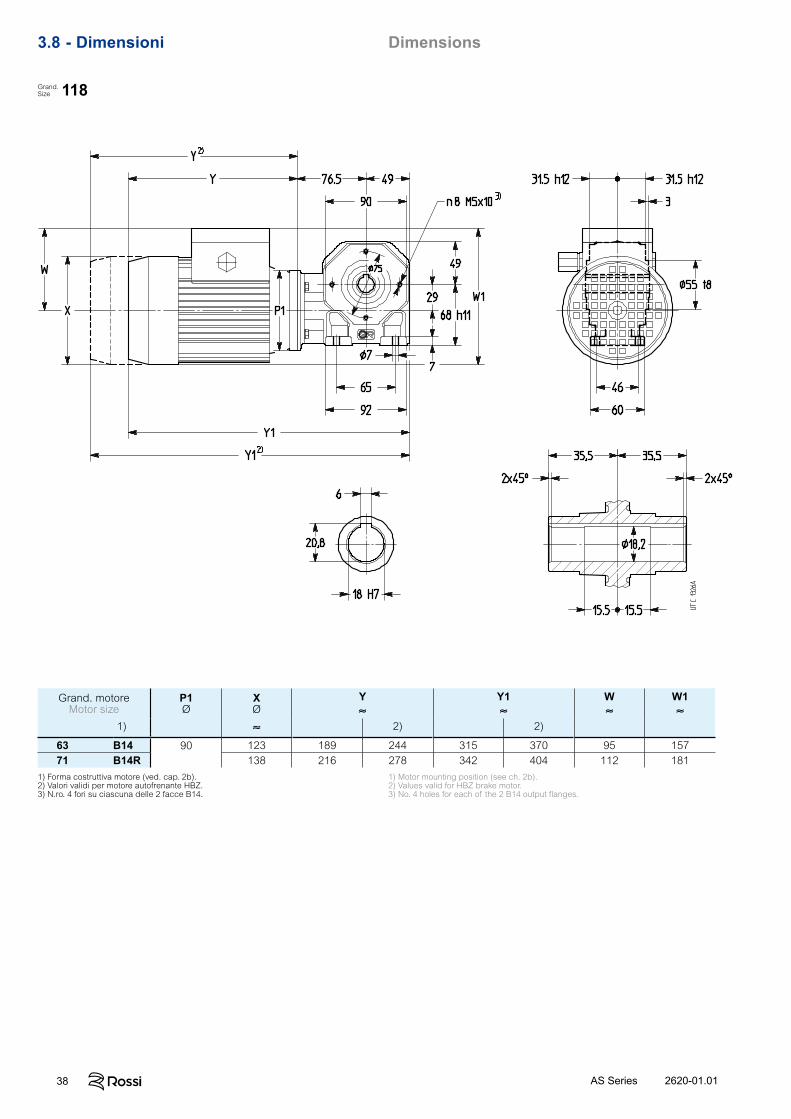
38 2620-01.01AS Series
3.8 - Dimensioni Dimensions
Grand. motoreMotor size
P1Ø
XØ
Y≈
Y1≈
W≈
W1≈
1) ≈ 2) 2)
63 B14 90 123 189 244 315 370 95 15771 B14R 138 216 278 342 404 112 181
1) Forma costruttiva motore (ved. cap. 2b).2) Valori validi per motore autofrenante HBZ.3) N.ro. 4 fori su ciascuna delle 2 facce B14.
1) Motor mounting position (see ch. 2b).2) Values valid for HBZ brake motor.3) No. 4 holes for each of the 2 B14 output flanges.
118Grand.Size
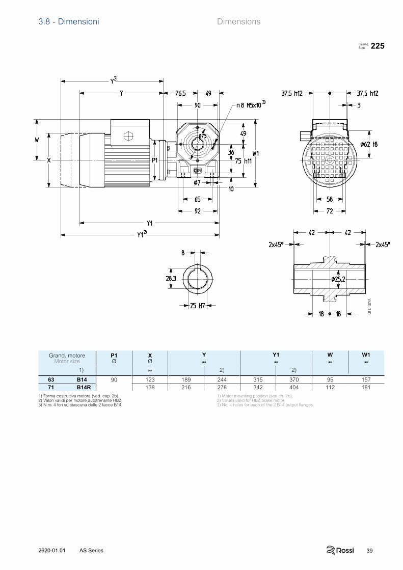
392620-01.01 AS Series
3.8 - Dimensioni Dimensions
225Grand.Size
Grand. motoreMotor size
P1Ø
XØ
Y≈
Y1≈
W≈
W1≈
1) ≈ 2) 2)
63 B14 90 123 189 244 315 370 95 15771 B14R 138 216 278 342 404 112 181
1) Forma costruttiva motore (ved. cap. 2b).2) Valori validi per motore autofrenante HBZ.3) N.ro. 4 fori su ciascuna delle 2 facce B14.
1) Motor mounting position (see ch. 2b).2) Values valid for HBZ brake motor.3) No. 4 holes for each of the 2 B14 output flanges.
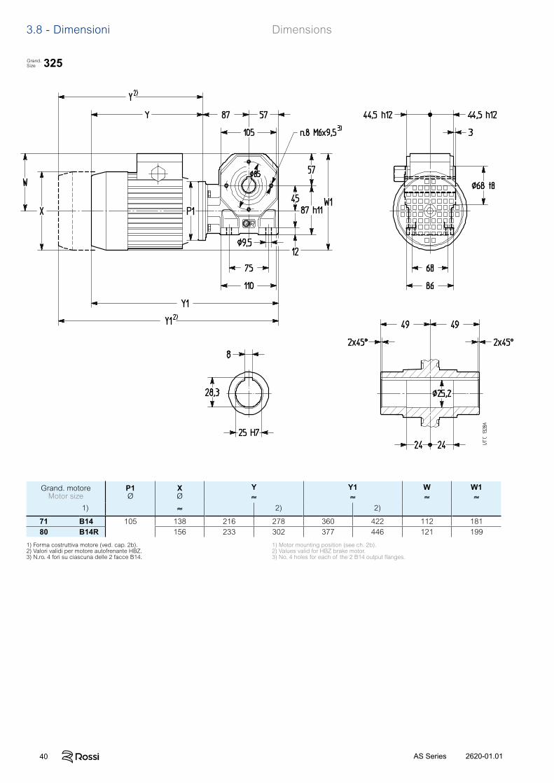
40 2620-01.01AS Series
3.8 - Dimensioni Dimensions
325Grand.Size
Grand. motoreMotor size
P1Ø
XØ
Y≈
Y1≈
W≈
W1≈
1) ≈ 2) 2)
71 B14 105 138 216 278 360 422 112 18180 B14R 156 233 302 377 446 121 199
1) Forma costruttiva motore (ved. cap. 2b).2) Valori validi per motore autofrenante HBZ.3) N.ro. 4 fori su ciascuna delle 2 facce B14.
1) Motor mounting position (see ch. 2b).2) Values valid for HBZ brake motor.3) No. 4 holes for each of the 2 B14 output flanges.
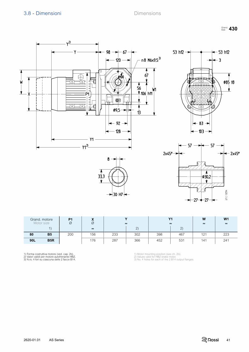
412620-01.01 AS Series
3.8 - Dimensioni Dimensions
430Grand.Size
Grand. motoreMotor size
P1Ø
XØ
Y≈
Y1≈
W≈
W1≈
1) ≈ 2) 2)
80 B5 200 156 233 302 398 467 121 223
90L B5R 176 287 366 452 531 141 241
1) Forma costruttiva motore (ved. cap. 2b).2) Valori validi per motore autofrenante HBZ.3) N.ro. 4 fori su ciascuna delle 2 facce B14.
1) Motor mounting position (see ch. 2b).2) Values valid for HBZ brake motor.3) No. 4 holes for each of the 2 B14 output flanges.
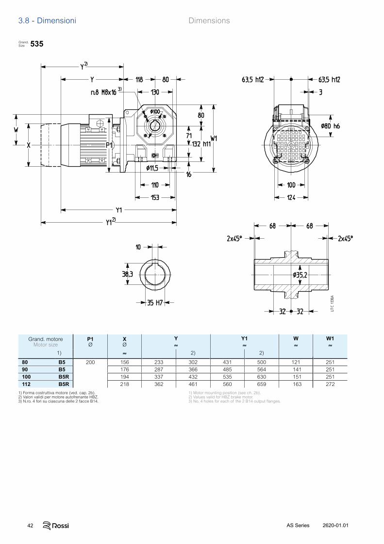
42 2620-01.01AS Series
3.8 - Dimensioni Dimensions
535Grand.Size
Grand. motoreMotor size
P1Ø
XØ
Y≈
Y1≈
W≈
W1≈
1) ≈ 2) 2)
80 B5 200 156 233 302 431 500 121 25190 B5 176 287 366 485 564 141 251100 B5R 194 337 432 535 630 151 251112 B5R 218 362 461 560 659 163 272
1) Forma costruttiva motore (ved. cap. 2b).2) Valori validi per motore autofrenante HBZ.3) N.ro. 4 fori su ciascuna delle 2 facce B14.
1) Motor mounting position (see ch. 2b).2) Values valid for HBZ brake motor.3) No. 4 holes for each of the 2 B14 output flanges.
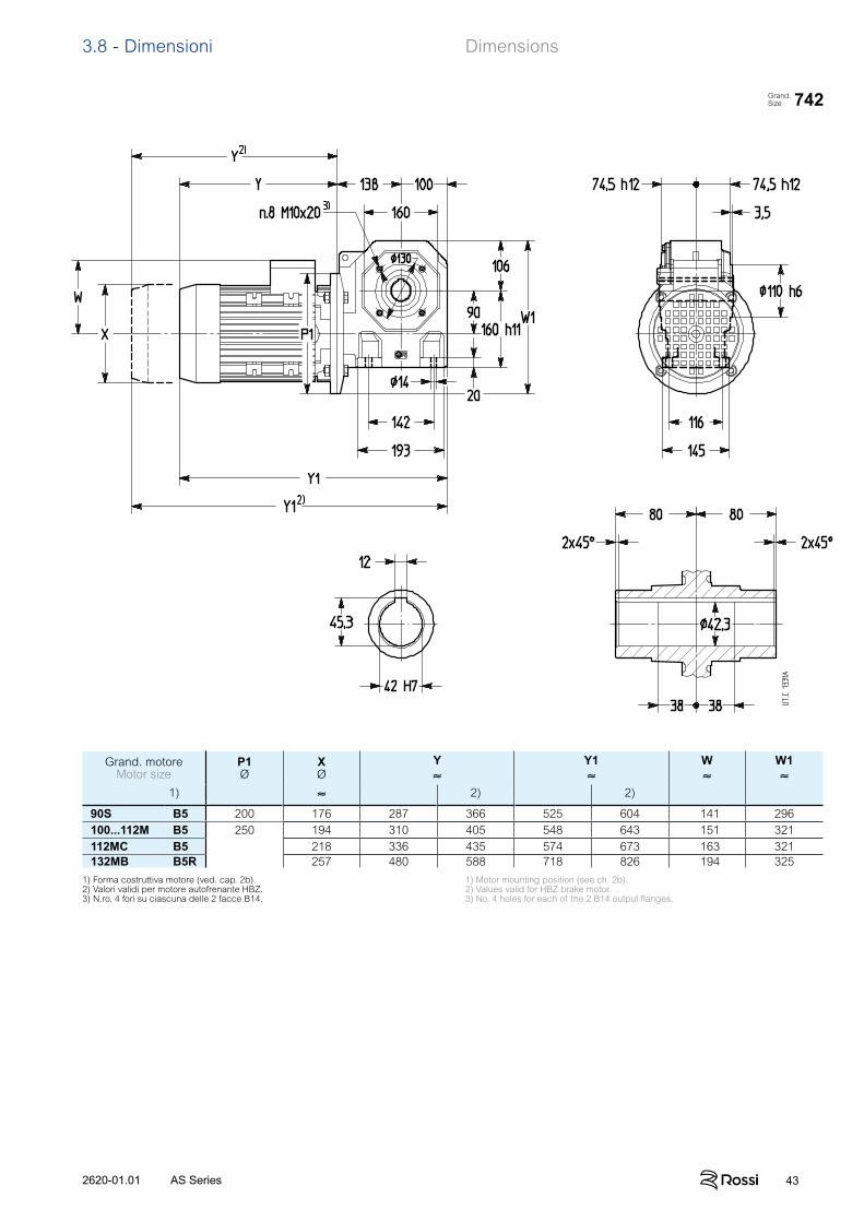
432620-01.01 AS Series
3.8 - Dimensioni Dimensions
742Grand.Size
Grand. motoreMotor size
P1Ø
XØ
Y≈
Y1≈
W≈
W1≈
1) ≈ 2) 2)
90S B5 200 176 287 366 525 604 141 296100...112M B5 250 194 310 405 548 643 151 321112MC B5 218 336 435 574 673 163 321132MB B5R 257 480 588 718 826 194 325
1) Forma costruttiva motore (ved. cap. 2b).2) Valori validi per motore autofrenante HBZ.3) N.ro. 4 fori su ciascuna delle 2 facce B14.
1) Motor mounting position (see ch. 2b).2) Values valid for HBZ brake motor.3) No. 4 holes for each of the 2 B14 output flanges.

44 2620-01.01AS Series
3.9 - Dettagli costruttivi e funzionali Structural and operational details
Ingranaggio a vite Worm gear pairNumero di denti z2 della ruota a vite e z1 della vite, modulo assiale mx, inclinazione d’elica media m, rendimento statico s dell’ingra-naggio a vite.
Number of teeth – wormwheel z2 and worm z1 – axial module mx, reference lead angle m, static efficiency s of the worm gear pair.
Gioco angolare asse lentoIl gioco angolare dell’asse lento, a vite bloc-cata, è compreso orientativamente tra i va-lori indicati in tabella. Esso varia in funzione dell’esecuzione e della temperatura.
1) Alla distanza di 1 m dal centro dell’asse lento, il gioco angolare in mm si ottiene moltiplicando per 1 000 i valori di tabella (1 rad = 3438’).
Low speed shaft angular backlashA rough guide for low speed shaft angular backlash is given in the table (the worm being held stationary). Values vary according to de-sign and temperature.
1) At a distance of 1 m from the low speed shaft centre, angu-lar backlash in mm is obtained multiplying the table value by 1 000 (1 rad = 3438’).
Grandezzariduttore
Gear reducersize
Gioco angolare [rad]1)
Angular backlash [rad]1)
min max
118 0,0034 0,0132225 0,0028 0,0112325 0,0023 0,0090430 0,0019 0,0075535 0,0017 0,0067742 0,0015 0,0056
Grandezza riduttore - Gear reducer size
iN 118 225 325 430 535 742
6 z2/z1 18/3mx 2,2 – – – – –m 22° 29’s 0,71
8,5 z2/z1 17/2 25/3 25/3 25/3 33/4 33/4mx 2,3 2,2 2,8 3,4 3,5 4,5m 15° 10’ 22° 29’ 22° 29’ 22° 37’ 28° 37’ 28° 33’s 0,65 0,71 0,71 0,71 0,74 0,74
11,8 z2/z1 22/2 24/2 24/2 24/2 35/3 35/3mx 1,8 2,3 2,8 3,5 3,3 4,2m 13° 29’ 15° 10’ 15° 10’ 15° 07’ 19° 52’ 20° 28’s 0,62 0,65 0,65 0,65 0,69 0,7
16 z2/z1 28/2 31/2 31/2 31/2 31/2 31/2mx 1,5 1,8 2,3 2,9 3,7 4,7m 11° 58’ 13° 29’ 13° 14’ 13° 36’ 14° 23’ 14° 48’s 0,6 0,62 0,62 0,63 0,64 0,64
19 z2/z1 17/1 38/2 38/2 38/2 38/2 38/2mx 2,3 1,5 1,9 2,4 3,1 3,9m 7° 43’ 11° 58’ 11° 53’ 12° 04’ 12° 47’ 13° 14’s 0,5 0,6 0,6 0,6 0,61 0,62
23,6 z2/z1 22/1 24/1 24/1 24/1 47/2 47/2mx 1,9 2,3 2,8 3,5 2,5 3,2m 6° 55’ 7° 43’ 7° 40’ 7° 46’ 11° 46’ 12° 01’s 0,48 0,5 0,5 0,5 0,6 0,6
30 z2/z1 28/1 30/1 30/1 30/1 30/1 30/1mx 1,5 1,9 2,4 3 3,8 4,8m 6° 00’ 6° 55’ 6° 52’ 6° 58’ 7° 21’ 7° 34’s 0,45 0,48 0,48 0,48 0,5 0,5
37,5 z2/z1 35/1 38/1 38/1 37/1 37/1 37/1mx 1,3 1,5 1,9 2,4 3,1 3,9m 5° 14’ 6° 00’ 6° 00’ 6° 03’ 6° 25’ 6° 38’s 0,42 0,45 0,45 0,45 0,46 0,47
47,5 z2/z1 44/1 47/1 47/1 47/1 47/1 47/1mx 1 1,3 1,6 2 2,5 3,2m 4° 30’ 5° 14’ 5° 10’ 5° 16’ 5° 54’ 6° 02’s 0,38 0,42 0,42 0,42 0,44 0,45
60 z2/z1 58/1 58/1 58/1 58/1 58/1mx – 1 1,3 1,6 2,1 2,7m 4° 30’ 4° 25’ 4° 32’ 5° 07’ 5° 15’s 0,38 0,38 0,38 0,41 0,42
75 z2/z1 73/1 73/1 73/1 73/1mx – – 1 1,3 1,7 2,1m 3° 43’ 3° 50’ 4° 21’ 4° 27’s 0,34 0,35 0,38 0,38
452620-01.01 AS Series
3.9 - Dettagli costruttivi e funzionali Structural and operational details
Rendimento Il rendimento del riduttore è dato dal rapporto P2 / P1 (ved. cap. 3.7). I valori del rendimento così calcolati sono validi per condizioni di lavoro normali, vite motrice e lubrificazione corretta, dopo un buon rodaggio (ved. cap. 4) e con un carico vicino al valore nominale.Il rendimento è più basso (di circa il 12% per viti con z1 = 1; 6% per viti con z1 = 2; 3% per viti con z1 = 3) nelle prime ore di funziona-mento (circa 50 ore) e, in generale, ad ogni avviamento a freddo.Allo spunto il rendimento «statico» s (ved. tabella al paragrafo precedente) è molto più basso di (per il fatto che a velocità 0 si deve vincere l’attrito di «primo distacco»); all’aumentare della velo-cità il rendimento aumenta fino a raggiungere il valore di catalogo.Il rendimento inverso inv, che si ha quando la ruota a vite è motri-ce, è sempre inferiore a . Può essere calcolato, con una buona approssimazione, con la formula:
inv ≈ 2 – 1 / ; analogamente: s inv ≈ 2 – 1 / s
IrreversibilitàIl motoriduttore a vite è dinamicamente irreversibile (cessa istanta-neamente di ruotare quando sull’asse della vite non ci sono più cause che mantengano in rotazione la vite stessa, es.: momento motore, inerzia dovuta alla vite, motore, volani, giunti, ecc.) quando 0,5 in quanto inv diventa minore di 0.Questa condizione è necessaria quando c’è l’esigenza di arre-stare e trattenere il carico, anche senza l’intervento di un freno. In presenza di vibrazioni continue l’irreversibilità dinamica può non essere possibile.Il motoriduttore è staticamente irreversibile (non è possibile met-terlo in rotazione dall’asse lento) quando s 0,5.Questa condizione è necessaria quando c’è l’esigenza di mante-nere in sosta il carico; in pratica, tenuto conto che i rendimenti possono migliorare con il funzionamento, è consigliabile che sia s 0,4 (m 5°). In presenza di vibrazioni continue l’irreversibilità statica può non essere possibile.Il motoriduttore ha una bassa reversibilità statica (è possibile met-terlo in movimento dall’asse lento con momenti torcenti elevati e/o in presenza di vibrazioni) quando 0,5 s 0,6 (7° 30’ m 12°).Il motoriduttore ha una reversibilità statica completa (è possibile metterlo in movimento dall’asse lento) quando s 0,6 (m 12°).Questa condizione è consigliabile quando c’è l’esigenza di avviare con facilità il motoriduttore dall’asse lento.
SovraccarichiPoiché l’ingranaggio a vite è spesso sottoposto a elevati sovraccari-chi statici e dinamici, in quanto è particolarmente idoneo a soppor-tarli, si presenta – più frequentemente che per altri tipi di ingranag-gio – la necessità di verificare che il valore di questi sovraccarichi sia sempre inferiore a M2 max (cap. 3.7).Normalmente si generano sovraccarichi quando si hanno:– avviamenti a pieno carico (specialmente per elevate inerzie e
bassi rapporti di trasmissione), frenature, urti;– casi di motoriduttori irreversibili o poco reversibili in cui la ruota
a vite diventa motrice per effetto delle inerzie della macchina azionata;
– potenza applicata superiore a quella richiesta; altre cause stati-che o dinamiche.
Qui di seguito vengono date alcune considerazioni generali su questi so vraccarichi e, per alcuni casi tipici, alcune formule per la loro valu-tazione.Quando non è possibile valutarli, inserire dispositivi di sicurezza in modo da non superare mai M2 max.
Momento torcente di spuntoQuando l’avviamento è a pieno carico (specialmente per elevate iner-zie e bassi rapporti di trasmissione), verificare che M2 max sia maggiore o uguale al momento torcente di spunto il quale può essere calcolato con la formula:
M2 spunto = M spuntoMN
· M2 disponibile – M2 richiesto JJ + J0 · + M2 richiesto
dove:M2 richiesto è il momento torcente assorbito dalla macchina per lavoro e attriti;M2 disponibile è il momento torcente in uscita dovuto alla potenza nominale del motore;J0 è il momento d’inerzia (di massa) del motore (ved. cat. TX);J è il momento d’inerzia (di massa) esterno (riduttore, giunti, macchina azionata) in kg m2, riferito all’asse del motore;per gli altri simboli ved. cat. TX.
NOTA: quando si vuole verificare che il momento torcente di spunto sia sufficientemente elevato per l’avviamento, considerare, nella valutazione di M2 disponibile il rendimento s, e nella valutazione di M2 richiesto, eventuali attriti di primo distacco.
Efficiency Gear reducer efficiency is given by P2 / P1 ratio (see ch. 3.7). The values obtained will be valid assuming normal working conditions, worm operating as driving member, proper lubrication, adequate running-in (see ch. 4), and a load near to the nominal value.During the initial working period (about 50 hours) and generally at every cold start, efficiency will be lower (by about 12% for worms with z1 = 1; 6% for worms with z1 = 2 and 3% for worms with z1 = 3).«Static» efficiency s on starting (see table in the preceding sec-tion) is much lower than (since «starting friction» must be over-come at speed 0); as speed picks up gradually, efficiency will rise correspondingly until the catalogue value is reached.Inverse efficiency inv, – produced by the wormwheel as driver – is always less than . It can be calculated approximately as fol-lows:
inv ≈ 2 – 1 / ; likewise: s inv ≈ 2 – 1 / s
IrreversibilityThe worm gearmotor is dynamically irreversible (that is, it ceases to turn the instant the wormshaft receives no further stimulus that would keep the worm itself in rotation e.g. motor torque, inertia from the worm, motor, flywheels, couplings, etc.) when 0,5 as inv then drops below 0.This state becomes necessary wherever there is a need for stop-ping and holding the load, even without the aid of a brake. Where continuous vibration occurs, dynamic irreversibility may not be obtainable.The gearmotor is statically irreversible (that is, rotation cannot be imparted by way of the low speed shaft) when s 0,5.This is a state necessary to keep the load at standstill; taking into account, however, that efficiency can increase with time spent in opera-tion, it would be advisable to assume s 0,4 (m 5°).Where continuous vibration occurs, static irreversibility may not be obtainable.The gearmotor has low static reversibility (i.e. rotation may be imparted by way of the low speed shaft with high torque and/or vibra-tion) when 0,5 s 0,6 (7° 30’ m 12°).The gearmotor has complete static reversibility (i.e. rotation may be imparted by way of the low speed shaft) when s 0,6 (m 12°).This state is advisable where there is a need for easy start-up of the gearmotor by way of the low speed shaft.
OverloadsSince worm gear pairs are often subject to high static and dynamic overloads by dint of the fact that they are especially suited to bear them, the need arises – more so than with other gear pairs – to verify that such overloads will always remain lower than M2 max (ch. 3.7).Overloads are normally generated when one has:– starting on full load (especially for high inertias and low trans-
mission ratios), braking, shocks;– irreversible gearmotors or gearmotors with low reversibility in
which the worm-wheel becomes driver due to driven machine inertia;
– applied power higher than that required; other static or dynamic causes.
The following general observations on overloads are accompanied by some formulae for carrying out evaluations in certain typical instances.Where no evaluation is possible, install safety devices which will keep values within M2 max.
Starting torqueWhen starting on full load (especially for high inertias and low trans-mission ratios) verify that M2 max is equal to or greater than starting torque, by using the following formula:
M2 start = M startMN
· M2 available – M2 required JJ + J0· + M2 required
where:M2 required is torque absorbed by the machine through work and friction;M2 available is output torque derived from the motor’s nominal power rating;J0 is the moment of inertia (of mass) of the motor (see cat. TX);J is the external moment of inertia (of mass) in kg m2 (gear reducers, couplings, driven machine) referred to the motor shaft;for other symbols see cat TX.
NOTE: When seeking to verify that starting torque is sufficiently high for starting, take into account efficiency s when evaluating M2 available, and starting friction, if any, in evaluat-ing M2 required.
46 2620-01.01AS Series
3.9 - Dettagli costruttivi e funzionali Structural and operational details
Arresti di macchine con elevata energia cinetica (elevati mo menti d’inerzia con elevate velocità) senza o con frenature (con motore autofrenante o freno sull’asse della vite)Scegliere sempre un riduttore staticamente reversibile (s 0,5); se il motore è autofrenante verificare la sollecitazione di frenatura con la formula:
M fs inv
· i + M2 richiesto JJ + J0 /s inv
– M2 richiesto M2 max
dove:M f è il momento frenante di taratura (ved. cat. TX);s inv è il rendimento statico inverso (ved. paragrafo precedente);per gli altri simboli ved. sopra e cap. 1.
Quando non è possibile scegliere un motoriduttore staticamente reversibile (cioè s 0,5) occorre che il rallentamento sia sufficien-temente dolce (per evitare sollecitazioni troppo elevate al riduttore stesso) in modo che sia:
– M2 M2 max
dove:J2 [kg m2] è il momento d’inerzia (di massa) della macchina azionata riferito all’asse lento del motoriduttore;M2 [N m] è il momento torcente assorbito dalla macchina per lavoro e attriti;2 [rad/s2] è la decelerazione angolare dell’asse lento; può essere diminuita per mezzo di rampe elettriche di decelerazione, diminuzione del momento frenante quando c’è frenatura, ecc.
Il valore di 2 può essere valutato sulla base di considerazioni (in sicurezza) teoriche oppure sperimentalmente (per mezzo del tempo e dello spazio di arresto, ecc.). Se il motore è autofrenante 2 può essere valutato (prudenzialmente) con la formula:
2 = Mf
J0 · i
in cui si considera il motore a vuoto e sottoposto al momento frenante di taraturaMf [N m] (ved. cat. TX).
Funzionamento con motore autofrenanteTempo di avviamento ta e angolo di rotazione del motore a1
ta = (J0 + J / ) · n1 [s]; a1 = ta · n1
19,1[rad] 9,55 M spunto – M2 richiesto
i · Tempo di frenatura t f e angolo di rotazione del motore f1
t f = (J0 + J / inv) · n1 [s]; f1 = t f · n1
19,1[rad] 9,55 Mf + M2 richiesto · inv
i dove:
M spunto [N m] è il momento torcente di spunto del motore 9550 · P1
n1 ·
M spuntoMN
(ved. cat. TX);M f [N m] è il momento frenante di taratura del motore (ved. cat. TX);per altri simboli ved. sopra e cap. 1.
La ripetitività di frenatura, con riduttore rodato e a regime termico, al variare della temperatura del freno e dello stato di usura della guarnizione di attrito è – entro i limiti normali del traferro e dell’u-midità ambiente e con adeguata apparecchiatura elettrica – circa± 0,1 · f1.Nella fase di riscaldamento (0,5 2 h dalle grandezze piccole alle grandi) i tempi e gli spazi di frenatura tendono ad aumen-tare fino a stabilizzarsi attorno ai valori corrispondenti ai rendimenti di catalogo.
Durata della guarnizione di attritoOrientativamente (ved. documentazione specifica) il nu mero di frenature ammesso tra due registrazioni è dato dalla formula:
W · 106
M f · f1dove:W [MJ] è il lavoro di attrito fra due registrazioni del traferro indicato in tabel-la; per altri simboli ved. sopra.
Il valore del traferro va da un minimo di 0,25 a un massi mo di 0,7; orientativamente il numero di registrazioni è 5.
Stopping machines with high kinetic energy (high moments of inertia combined with high speeds) with or without braking (braking applied to wormshaft, or use of brake motor)Select a gear reducer with static reversibility (s 0,5); if using a brake motor, verify braking stress with the following formula:
M fs inv
· i + M2 required JJ + J0 /s inv
– M2 required M2 max
where:M f is the braking torque setting (see cat. TX);s inv is static inverse efficiency (see previous heading);for other symbols see above and ch.1.
Where selection of a statically reversible gearmotor is not possible (i.e. s 0,5) slowing-down should be sufficiently gradual (avoiding application of excessive stress to the unit itself) as to ensure that:
– M2 M2 max
where:J2 [kg m2] is the moment of inertia (of mass) of the driven machine referred to the gear motors low speed shaft;M2 [N m] is torque absorbed by the machine through work and friction;2 [rad/s2] is the low speed shaft’s angular deceleration; this may be reduced by electric deceleration ramps, lowering of braking torque when braking systems are in use, etc.
2 may be arrived at theorically (within broadly safe limits) or experimentally (by testing against stopping time and distance etc.).If a brake motor is in use, the following formula may be used for a safe evaluation of 2:
2 = MfJ0 · i
in which the motor is presumed without load and subject to its braking torque settingMf [N m] (see cat. TX).
Operation with brake motorStating time ta and revolutions of motor a1
ta = (J0 + J / ) · n1 [s]; a1 = ta · n1
19,1[rad] 9,55 M start – M2 required
i · Braking time t f and revolutions of motor f1
t f = (J0 + J / inv) · n1 [s]; f1 = t f · n1
19,1[rad] 9,55 Mf + M2 required · inv
i where:
M start [N m] is motor starting torque 9550 · P1
n1
· M start
MN (see cat. TX);
M f [N m] is the braking torque setting of the motor (see cat. TX);for other symbols see above and ch. 1.
With the gear reducer run in and operating at normal running tem-perature – assuming a regular air-gap and ambient humidity and utilizing suitable electrical equipment – repetition of the braking action, as affected by variation in temperature of the brake and by the state of wear of friction surface, is approx ± 0,1 · f1.During warm-up (0,5 2 h, small through to large sizes), braking
times and distances tend to increase to the point of stabilizing at or around values corresponding to rated catalogue efficiency.
Duration of friction surfaceAs a rough guide (see specific literature), the num-ber of applications permissible between successive adjustments of the air-gap is given by the following formula:
W · 106
M f · f1where:W [MJ] is the work of friction between successive adjustments of the air-gap as indicated in the table: for other symbols see above.
The air-gap should measure between 0,25 minimum and 0,7 maximum; as a rough guide, 5 adjustments can be made.
Grandezza motore W
Motor size MJ
63 10,6 71 14 80 18 90 24 100 24 112 45 132 67
J2. 2 J2
. 2
Grandezza motore W
Motor size MJ
63 10,6 71 80 18 90 24 100 112 132
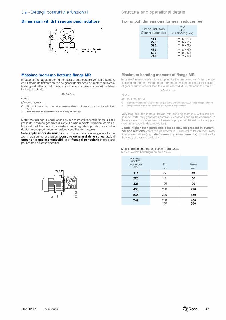
472620-01.01 AS Series
Dimensioni viti di fissaggio piedi riduttore Fixing bolt dimensions for gear reducer feet
Grand. riduttoreGear reducer size
ViteBolt
UNI 5737-88 (l max)
118 M 6 x 18225 M 6 x 25325 M 8 x 35430 M 8 x 40535 M10 x 50742 M12 x 60
Massimo momento flettente flange MRIn caso di montaggio motori di fornitura cliente occorre verificare sempre che il momento flettente statico Mb generato dal peso del motore sulla con-troflangia di attacco del riduttore sia inferiore al valore ammissibile Mbmax indicato in tabella:
Mb Mbmax
dove:
Mb = G · X / 1000 [N m]
G [N] peso del motore; numericamente circa uguale alla massa del motore, espressa in kg, moltiplicata per 10
X [mm] distanza del baricentro del motore dal piano flangia.
Motori molto lunghi e snelli, anche se con momenti flettenti inferiore ai limiti prescritti, possono generare durante il funzionamento vibrazioni anomale. In questi casi è opportuno prevedere una adeguata sopportazione ausilia-ria del motore (ved. documentazione specifica del motore).Nelle applicazioni dinamiche in cui il motoriduttore è soggetto a trasla-zioni, rotazioni od oscillazioni possono generarsi delle sollecitazioni superiori a quelle ammissibili (es.: fissaggi pendolari): interpellarci per l’esame del caso specifico.
Maximum bending moment of flange MRIn case of assembly of motors supplied by the customer, verify that the sta-tic bending moment Mb generated by motor weight on the counter flange of gear reducer is lower than the value allowed Mbmax, stated in the table:
Mb Mbmax
where:
Mb = G · X / 1000 [N m]
G [N] motor weight; numerically nearly equal to motor mass, expressed in kg, multiplied by 10X [mm] distance from motor center of gravity from fl ange surface
Very long and thin motors, though with bending moments within the pre-scribed limits, may generate anomalous vibrations during the operation. In these cases it is necessary to foresee a proper additional motor support (see motor specific documentation).
Loads higher than permissible loads may be present in dynami-cal applications where the gearmotor is subjected to translations, rota-tions or oscillations (e.g.: shaft mounting arrangements): consult us for the study of every specific case
Massimo momento flettente ammissibile Mbmax Max allowable bending momento Mbmax
Grandezza riduttore
Gear reducer size
P1 Mbmax
Ø N m
118 90 56
225 90 56
325 105 90
430 200 280
535 200 450
742 200 450250 900
3.9 - Dettagli costruttivi e funzionali Structural and operational details
48 2620-01.01AS Series
4
Accessori ed esecuzioni speciali
48 2620-01.01AS Series
speciali
48 2620-01.01AS Series
492620-01.01 AS Series
Accessories and non-standard designs
492620-01.01 AS Series
designs
Section content
4.1 Alberi lenti Low speed shafts 50
4.2 Flangia Flange 50
4.3 Sistemi di fi ssaggio pendolare Shaft-mounting arrangements 51
4.4 Protezioni albero lento cavo STANDARDFIT Hollow low speed shaft STANDARDFIT protections 51
50 2620-01.01AS Series
4 - Accessori ed esecuzioni speciali Accessories and non-standard designs
4.1 - Alberi lentiL'accessorio viene fornito montato sul riduttore. Se non diversamen-te specificato, la posizione di montaggio dell'albero lento normale è con l'estremità sporgente sul fianco destro riduttore, in forma co-struttiva B3, vista lato motore. Per posizione di montaggio opposta precisare di seguito alla designazione «montato lato opposto».
Low speed shaftsThe accessory is supplied fitted onto the gear reducer. If not differ-ently stated, the standard mounting position for the low speed shaft end is on gear reducer right hand side – B3 mounting position – seen from motor side. For reverse mounting, specify in designation «mounted on opposite side».
Grand.rid.
Gearreducer
size
D∅
E Linguetta esternaExternal
key
D1 h L1 L2 l 2 Z ViteBolt
MassaMass
NormaleStand.
Bisp.Doubl.extens.
h7 b x h x l UNI 5739-65 kg kg
118 18 30 6 x 6 x 25 28 4 101 131 36 71 M6 × 20 0,2 0,3225 25 42 8 x 7 x 36 35 5 126 168 45 84 M8 × 25 0,5 0,6325 25 42 8 x 7 x 36 35 5 140 182 63 98 M8 × 25 0,5 0,7
430 30 58 8 x 7 x 45 47 5 172 230 63 114 M10 × 30 0,9 1,3535 35 58 10 x 8 x 50 47 5 194 252 90 136 M10 × 30 1,5 1,9742 42 82 12 x 8 x 70 57 6 242 324 100 160 M12 × 401) 2,6 3,5
Il diametro esterno dell’elemento o del distanziale in battuta contro il riduttore deve es-sere (1,25 ÷ 1,4) · D.
Descrizione aggiuntiva alla designazione per l’ordinazione: albero lento normale o bisporgente.
The shoulder outer diameter of the part, or of spacer abutting with the gear reducer must be (1,25 ÷ 1,4) · D.
Supplementary description when ordering by designation: stan-dard, or double extension low speed shaft.
4.2 FlangiaFlangia B5 con fori passanti e centraggio «foro».Disponibile in due varianti con differenti dimensioni di accoppia-mento: flangia B5 e flangia B5 tipo B.L'accessorio è fornito montato sul riduttore. Se non diversamente specificato, la posizione di montaggio è sul fianco destro riduttore, in forma costruttiva B3, vista lato motore. Per posizione di montag-gio opposta precisare di seguito alla designazione «montata lato opposto».Si raccomanda l’impiego, sia nelle viti sia nei piani di unione, di adesivi bloccanti.
FlangeB5 flange having clearance holes and spigot «recess».Available in two different options with different mating dimensions: B5 flange and B5 flange Type B.The accessory is supplied fitted onto the gear reducer. If not dif-ferently stated, the standard mounting position is on gear reducer right hand side – B3 mounting position – seen from motor side. For reverse mounting, specify in designation «mounted on opposite side».Locking adhesives are recommended both around threads and on mating surfaces.
Grand.rid.
Gearreducer
size
FØ
GØ
H1 H2 MØ
NØ
PØ
Q S V Z MassaMass
h12 h12 H7 kg
118 7 55 31,5 68 100 80 120 4 10 95 35,5 0,5225 7 62 37,5 74 100 80 120 4 10 95 42 0,5325 9,5 68 44,5 83 115 95 140 4 11 110 49 0,8
430 9,5 85 53 84 130 110 160 4,5 12 125 57 1535 11,5 80 63,5 105 165 130 200 4,5 14 152 68 2742 14 110 74,5 117 215 180 250 5 16 196 80 3,2
Descrizione aggiuntiva alla designazione per l’ordinazione: flangia B5 o flangia B5 tipo B.
Supplementary description when ordering by designation: flange B5 or B5 flange type B.
1) Vite UNI 5737-88 1) Bolt UNI 5737-88
Flangia B5 - B5 flange
Grand.rid.
Gearreducer
size
FØ
GØ
H1 H2 MØ
NØ
PØ
Q R S Z MassaMass
h12 h12 H7 kg
118 9,5 55 31,5 72 87 60 110 5 - 9 35,5 0,8225 11,5 62 37,5 87 90 70 125 5 - 10 42 1325 11,5 68 44,5 85 150 115 180 5 80 11 49 1,7
430 14 85 53 102 165 130 200 5 91 12 57 2,4535 14 80 63,5 112 176 152 210 6 - 14 68 2,9742 14 110 74,5 134 230 170 280 6 121 16 80 5,8
Flangia B5 tipo B - B5 flange type B
In caso di ordinazione separata dal riduttore la designazione dell'accessorio deve essere completata con l'indicazione del cata-logo e della grandezza riduttore cui si riferisce.
In case of separate order from the gear reducer's one, the acces-sory designation must include the catalog and gear reducers size data.
512620-01.01 AS Series
4 - Accessori ed esecuzioni speciali Accessories and non-standard designs
Braccio di reazioneVed. chiarimenti tecnici al cap. 4.
Torque armSee technical explanations at ch. 4.
Grand.rid.
Gearreducer
size
A B C d H1 m n s s1 M2
Ø Ø
H11 h12 ≈ N m
118 100 45 157 81) 31,5 5 9 4 4,7 95225 100 45 157 81) 37,5 5 9 4 4,7 95325 150 52,5 230 10 44,5 7 13 6 5,6 150
430 200 60 294 20 53 9,5 15,5 6 5,6 180535 200 60 294 20 63,5 9,5 15,5 6 7,5 335742 250 80 364 20 74,5 9,5 15,5 6 9,2 670
Descrizione aggiuntiva alla designazione per l’ordinazione: braccio di reazione.
Supplementary description when ordering by designation: torque arm.
1) Boccola ammortizzante di materiale plastico non presente.
2) Posizione non possibile per grand. 430.
1) Plastic damping bush not present.2) Position not possible for size 430.
L'accessorio, comprensivo delle viti di fissaggio al riduttore, viene fornito smontato. Il montaggio in direzione del motore non è possibile.
The accessory, including fixing bolts for gear reducer, is supplied not assembled. Fitting towards motor is not possible.
4.3 - Sistemi di fissaggio pendolareBullone di reazione a molle a tazzaVed. chiarimenti tecnici al cap. 4.
Shaft-mounting arrangementsReaction bolt using disc springsSee technical explanations at ch. 4.
Grand.rid.
Gearreducer
size
A B ViteBolt
Molla a tazzaDisc spring
T FØ
R1)
M2 2)
UNI 5737-88 DIN 2093 N m
118 32,5 23 M6 × 40 A 18 n.2 8 ÷ 10 8 4,9 −225 32,5 29 M6 × 40 A 18 n.2 8 ÷ 10 8 4,9 −325 37,5 34 M8 × 55 A 25 n.2 10 ÷ 14 11 6,5 −
430 46 41,5 M8 × 55 A 25 n.2 10 ÷ 14 11 6,5 −535 55 50 M12 × 70* A 35,5 n.2 14 ÷ 17 20 8,8 335742 71 58 M12 × 90 A 35,5 n.3 18 ÷ 25 20 10,8 600
Descrizione aggiuntiva alla designazione per l’ordinazione: bullone di reazione a molle a tazza.
Supplementary description when ordering by designation: reac-tion bolt using disc springs.
1) Valore teorico: tolleranza 0 -1.2) Per M2 maggiori impiegare 2 bulloni
di reazione o il braccio di reazione (ved. pag. 51).
* Vite modificata.
1) Theoretical value: tolerance 0 -1.2) For higher M2 values, utilize 2 reaction
bolts or the torque arm (see page 51). * Modified bolt.
4.4 - Protezione albero lento cavo Cappellotto di protezione della zona non utilizzata dell'albero lento cavo, di materiale plastico (polipropilene PP, colore nero).L'accessorio viene fornito smontato e completo di viti per il fissag-gio. Si raccomanda l'impiego di adesivi bloccanti sulle viti di fis-saggio.
Codice di esecuzione speciale per la designazione:Protezione albero lento cavo STANDARDFITIn caso di ordinazione separata dal riduttore la designazione dell'accessorio deve essere completata con l'indicazione del cata-logo e della grandezza riduttore cui si riferisce.
Hollow low speed shaft protection Protection hollow low speed shaft free area, made of plastic (polypropilene PP material color black)The accessory is supplied disassembled and complete with faste-ning screws. We recommend the use of locking adhesive on the screws.
Non standard design code for designation:Hollow low speed shaft STANDARDFIT protection In case of separate order from the gear reducer's one, the acces-sory designation must include the catalog and gear reducers size data.
Grand.rid.
Gearreducer
size
P P0 X s VitiScrews
Mserraggio
Mtightening
2)
Ø Ø H11 UNI 5931 N m
118, 225 90 48 20,5 1,5 M5×14 1,5325 105 50 20,5 1,6 M6×18 2,8430 120 61 24 1,7 M6×18 2,8
5351) 120 61 24 1,7 M8×20 6,3742 160 78 27,5 1,8 M10×20 12,3
1) Per grand. 535, la quota P del riduttore è pari a 130.1) For size 535, gear reducer P dimensions is equal to 130.2) Momento di serraggio.2) Tightening torque.
52 2620-01.01AS Series
5
Installazione emanutenzione
52 2620-01.01AS Series52 2620-01.01AS Series
532620-01.01 AS Series
Installation andmaintenance
532620-01.01 AS Series
Section content
5.1 Generalità General 54
5.2 Montaggio di organi sulle estremità d'albero Fitting of components to shaft end 54
5.3 Perno macchina Shaft end of driven machine 55
5.4 Sostituzione motore Motor replacement 55
5.5 Sistemi di fi ssaggio pendolare Shaft mounting arrangements 55
54 2620-01.01AS Series
5 - Installazione e manutenzione Installation and maintenance
5.1 - GeneralitàAssicurarsi che la struttura sulla quale viene fissato il motoriduttore sia piana, livellata e sufficientemente dimensionata per garantire la stabilità del fissaggio e l’assenza di vibrazioni, tenuto conto di tutte le forze trasmesse dovute alle masse, al momento torcente, ai carichi radiali e assiali.Collocare il motoriduttore in modo da garantire un am pio passaggio d’aria per il raffreddamento del riduttore e del motore (soprattutto dal lato ventola motore).Evitare: strozzature nei passaggi dell’aria; vicinanza con fonti di ca lore che possano influenzare la temperatura dell’aria di raffredda-mento e del motoriduttore per irraggiamento; insufficiente ricircola-zione d’aria e in generale applicazioni che compromettano il regolare smaltimento del calore.Montare il motoriduttore in modo che non subisca vibrazioni.In presenza di carichi esterni impiegare, se necessario, spine o arresti positivi.Nel fissaggio tra riduttore e macchina e/o tra riduttore ed eventuale flangia B5, si raccomanda l’impiego di adesivi bloccanti tipo LOC-TITE nelle viti di fissaggio (anche nei piani di unione per fissaggio con flangia).Per installazione all’aperto o in ambiente aggressivo verniciare il motoriduttore con vernice anticorrosiva, proteggendolo eventual-mente anche con grasso idrorepellente (specie in corrispondenza delle sedi rotanti degli anelli di tenuta e delle zone di accesso alle estremità dell’albero).Quando è possibile, proteggere il motoriduttore con opportuni accor-gimenti dall’irraggiamento solare e dalle intemperie: quest’ultima protezione diventa necessaria per forme costruttive B6, V5 e V6.Per temperatura ambiente maggiore di 40 °C o minore di 0 °C interpellarci.Prima di effettuare l’allacciamento del motoriduttore assicurarsi che la tensione del motore corrisponda a quella di alimentazione. Se il senso di rotazione non corrisponde a quello desiderato, invertire due fasi della linea di alimentazione.Nel caso si prevedano sovraccarichi di lunga durata, urti o pericoli di bloccaggio, installare salvamotori, limitatori elettronici di momen-to torcente, giunti di sicurezza, unità di controllo o altri dispositivi similari.Per servizi con elevato numero di avviamenti a carico è consigliabile la protezione del motore con sonde termiche (incorporate nello stesso): il relé termico non è idoneo in quanto dovrebbe essere tarato a valori superiori alla corrente nominale del motore.Limitare i picchi di tensione dovuti ai contattori mediante l’impiego di varistori.Attenzione! La durata dei cuscinetti e il buon funzionamento di alberi e giunti dipendono anche dalla precisione dell’alline-amento tra gli alberi. Pertanto, occorre prestare la massima cura nell’allineamento del motoriduttore con la macchina da comandare (se necessario, spessorare) interponendo tutte le volte che è possi-bile giunti elastici.Quando una perdita accidentale di lubrificante può comportare gra vi danni, aumentare la frequenza delle ispezioni e/o adottare accorgimenti opportuni (es.: indicatore a distanza di livello olio, lubrifican te per industria alimentare, ecc.).In presenza di ambiente inquinante, impedire in modo adeguato la possibilità di contaminazione del lubrificante attraverso gli anelli di tenuta o altro.Il motoriduttore non deve essere messo in servizio prima di essere incorporato su una macchina che risulti conforme alla di rettiva 98/37/CE.Per motori autofrenanti o speciali, richiedere documentazione speci-fica.
5.2 - Montaggio di organi sulle estremità d’alberoPer il foro degli organi calettati sull’estremità d’albero, si racco-manda la tolleranza K7; purchè il carico sia uniforme e leggero, la tolleranza può essere H7. Prima di procedere al montaggio pulire bene e lubrificare le superfi-ci di contatto per evitare il pericolo di grippaggio e l’ossidazione di contatto. Il montaggio e lo smontaggio si effettuano con l’ausilio di tiranti ed estrattori servendosi del foro filettato in testa all’estremità d’albero; per accoppiamenti H7/m6 e K7/j6 è consigliabile effettuare il montaggio a caldo riscaldando l’organo da calettare a 80 100 °C.
GeneralBe sure that the structure on which gearmotor is fitted is plane, le velled and sufficiently dimensioned in order to assure fitting sta-bility and vibration absence, keeping in mind all transmitted forces due to the masses, to the torque, to the radial and axial loads.Position the gearmotor so as to allow a free passage of air for cool-ing both gear reducer and motor (especially at motor fan side).Avoid: any obstruction to the air-flow; heat sources near the gear reducer that might affect the temperature of cooling-air and of gear motor for radiation; insufficient air recycle or any other factor hinder-ing the steady dissipation of heat.Mount the gearmotor so as not to receive vibrations.When external loads are present use pins or locking blocks, if ne ces sary.When fitting gear reducer and machine and/or gear reducer and eventual flange B5 it is recommended to use locking adhesives such as LOCTITE on the fastening screws (also on flange mating surfaces).For outdoor installation or in a hostile environment protect the gear motor with anticorrosion paint. Added protection may be afforded by water-repellent grease (especially around the rotary seating of seal rings and the accessible zones of shaft end).Gearmotors should be protected wherever possible, and by what-ever appropriate means, from solar radiation and extremes of weather; weather protection becomes essential for B6, V5 and V6 mounting positions.For ambient temperatures greater than 40 °C or less than 0 °C, consult us.Before wiring up the gearmotor, make sure that motor voltage corre-sponds to input voltage. If the direction of rotation is not as desired, invert two phases at the terminals.If overloads are imposed for long periods of time, or if shocks or danger of jamming are envisaged, then motor-protections, elec-tronic torque limiters, safety couplings, control units or other suitable devices should be fitted.Where duty cycles involve a high number of starts on load, it is advisable to utilize thermal probes (fitted on the wiring) for motor protection; a thermal overload relay is unsuitable since its threshold must be set higher than the motor’s nominal current rating.Use varistors to limit voltage peaks due to contactors.Warning! Bearing life, good shaft and coupling running depend on alignment precision between the shafts. Carefully align the gearmotor with the driven machine (with the aid of shims if need be), interposing flexible couplings whenever possible.Whenever a leakage of lubricant could cause heavy damages, in crease the frequency of inspections and/or envisage appropri-ate control devices (e.g.: remote oil level gauge, lubricant for food industry, etc.).In polluting surroundings, take suitable precautions against lubri-cant contamination through seal rings or other.Gearmotor should not be put into service before it has been incorpo-rated on a machine which is conform to 98/37/EC directive.For brake or non-standard motors, consult us for specific docu-mentation.
Fitting of components to shaft endsIt is recommended that the bore of parts keyed to shaft end is machined to K7 tolerance; H7 is permissible provided that load is uniform and light. Before mounting, clean mating surfaces thoroughly and lubricate against seizure and fretting corrosion.Installing and removal operations should be carried out with pullers and jacking screws using the tapped hole at the shaft butt-end; for H7/m6 and K7/j6 fits it is advisable that the part to be keyed is pre-heated to a temperature of 80 100 °C.
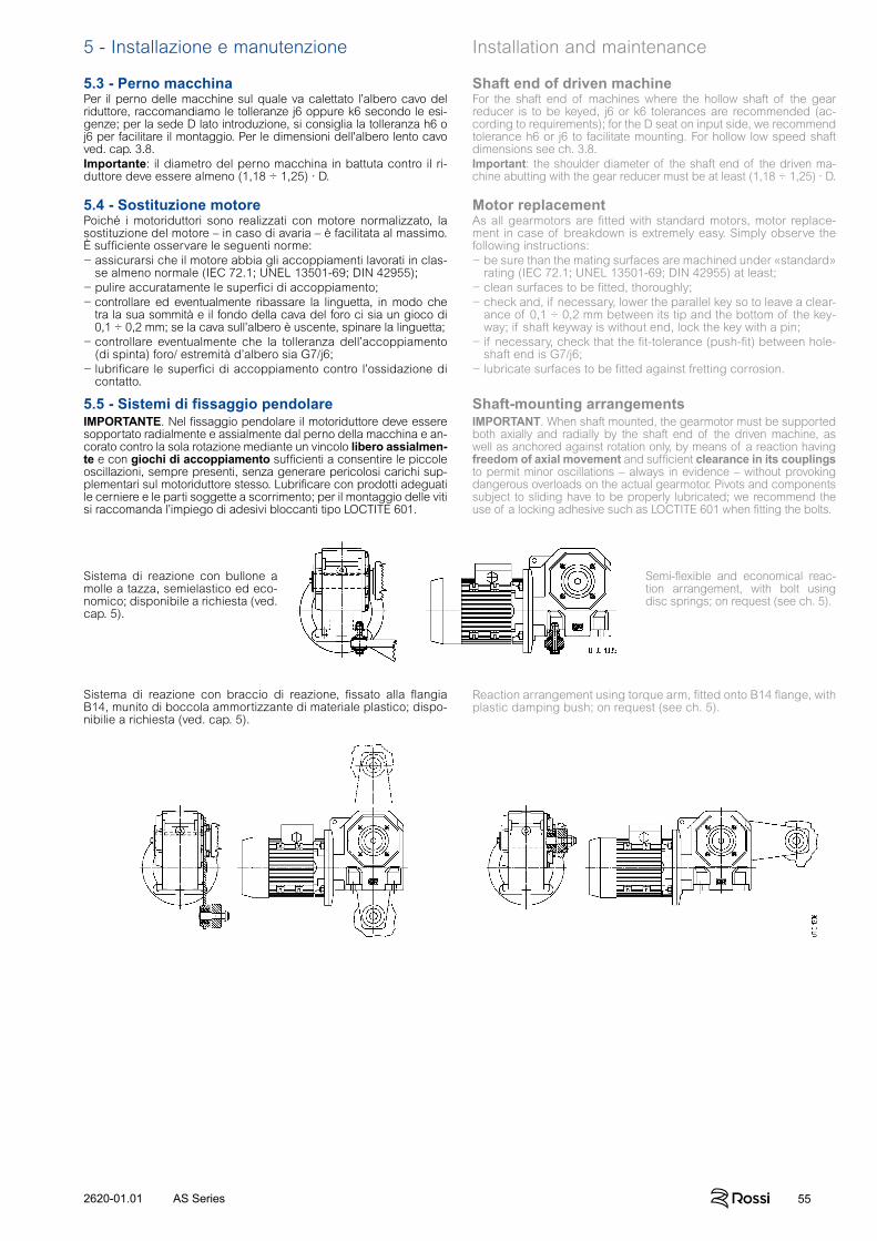
552620-01.01 AS Series
5 - Installazione e manutenzione Installation and maintenance
5.3 - Perno macchinaPer il perno delle macchine sul quale va calettato l’albero cavo del riduttore, raccomandiamo le tolleranze j6 oppure k6 secondo le esi-genze; per la sede D lato introduzione, si consiglia la tolleranza h6 o j6 per facilitare il montaggio. Per le dimensioni dell'albero lento cavo ved. cap. 3.8.Importante: il diametro del perno macchina in battuta contro il ri-duttore deve essere almeno (1,18 ÷ 1,25) · D.
Shaft end of driven machine For the shaft end of machines where the hollow shaft of the gear reducer is to be keyed, j6 or k6 tolerances are recommended (ac-cording to requirements); for the D seat on input side, we recommend tolerance h6 or j6 to facilitate mounting. For hollow low speed shaft dimensions see ch. 3.8.Important: the shoulder diameter of the shaft end of the driven ma-chine abutting with the gear reducer must be at least (1,18 ÷ 1,25) · D.
5.4 - Sostituzione motorePoiché i motoriduttori sono realizzati con motore normalizzato, la sostituzione del motore – in caso di avaria – è facilitata al massimo. È sufficiente osservare le seguenti norme:− assicurarsi che il motore abbia gli accoppiamenti lavorati in clas-
se almeno normale (IEC 72.1; UNEL 13501-69; DIN 42955);− pulire accuratamente le superfici di accoppiamento;− controllare ed eventualmente ribassare la linguetta, in modo che
tra la sua sommità e il fondo della cava del foro ci sia un gioco di 0,1 ÷ 0,2 mm; se la cava sull’albero è uscente, spinare la linguetta;
− controllare eventualmente che la tolleranza dell’accoppiamento (di spinta) foro/ estremità d’albero sia G7/j6;
− lubrificare le superfici di accoppiamento contro l’ossidazione di contatto.
Motor replacementAs all gearmotors are fitted with standard motors, motor replace-ment in case of breakdown is extremely easy. Simply observe the following instructions:− be sure than the mating surfaces are machined under «standard»
rating (IEC 72.1; UNEL 13501-69; DIN 42955) at least;− clean surfaces to be fitted, thoroughly;− check and, if necessary, lower the parallel key so to leave a clear-
ance of 0,1 ÷ 0,2 mm between its tip and the bottom of the key-way; if shaft keyway is without end, lock the key with a pin;
− if necessary, check that the fit-tolerance (push-fit) between hole-shaft end is G7/j6;
− lubricate surfaces to be fitted against fretting corrosion.
5.5 - Sistemi di fissaggio pendolareIMPORTANTE. Nel fissaggio pendolare il motoriduttore deve essere sopportato radialmente e assialmente dal perno della macchina e an-corato contro la sola rotazione mediante un vincolo libero assialmen-te e con giochi di accoppiamento sufficienti a consentire le piccole oscillazioni, sempre presenti, senza generare pericolosi carichi sup-plementari sul motoriduttore stesso. Lubrificare con prodotti adeguati le cerniere e le parti soggette a scorrimento; per il montaggio delle viti si raccomanda l’impiego di adesivi bloccanti tipo LOCTITE 601.
Shaft-mounting arrangementsIMPORTANT. When shaft mounted, the gearmotor must be supported both axially and radially by the shaft end of the driven machine, as well as anchored against rotation only, by means of a reaction having freedom of axial movement and sufficient clearance in its couplings to permit minor oscillations – always in evidence – without provoking dangerous overloads on the actual gearmotor. Pivots and components subject to sliding have to be properly lubricated; we recommend the use of a locking adhesive such as LOCTITE 601 when fitting the bolts.
Sistema di reazione con bullone a molle a tazza, semielastico ed eco-nomico; disponibile a richiesta (ved. cap. 5).
Semi-flexible and economical reac-tion arrangement, with bolt using disc springs; on request (see ch. 5).
Sistema di reazione con braccio di reazione, fissato alla flangia B14, munito di boccola ammortizzante di materiale plastico; dispo-nibilie a richiesta (ved. cap. 5).
Reaction arrangement using torque arm, fitted onto B14 flange, with plastic damping bush; on request (see ch. 5).
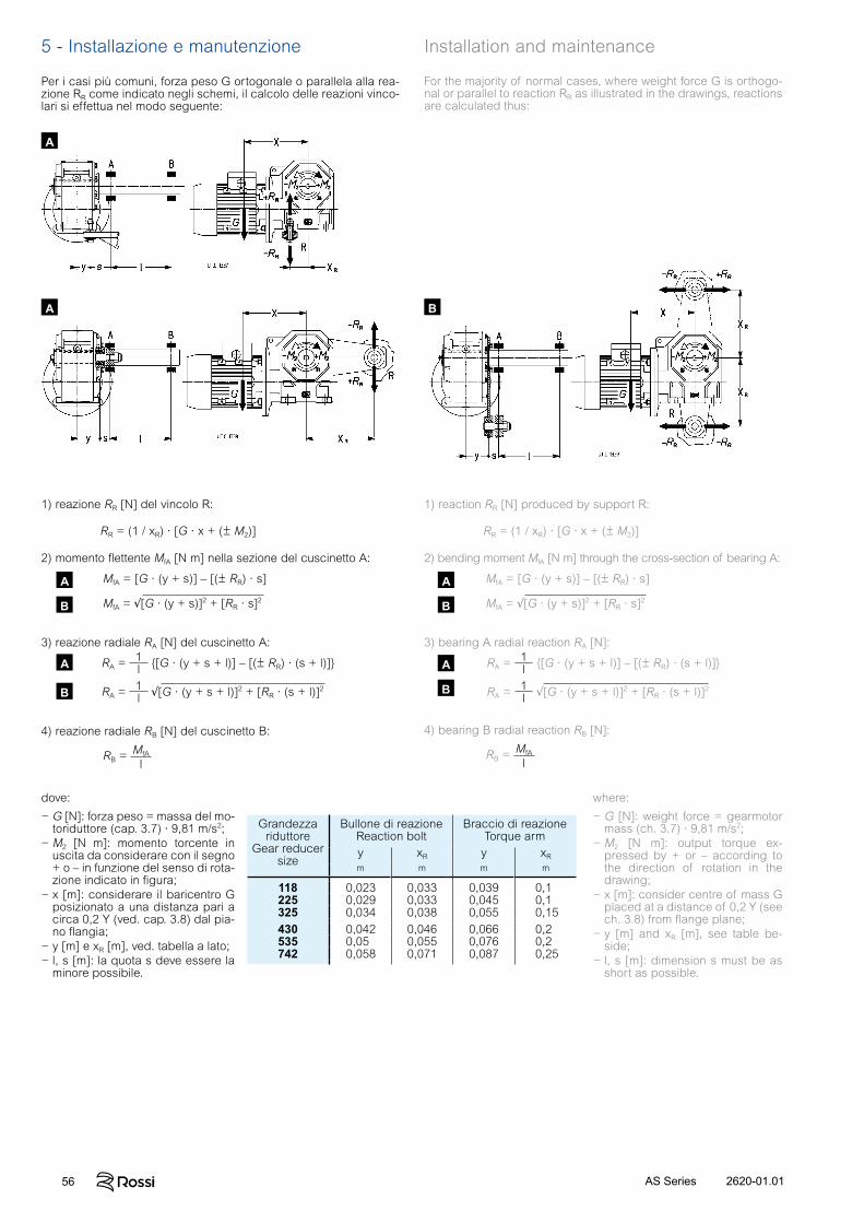
56 2620-01.01AS Series
2) momento flettente MfA [N m] nella sezione del cuscinetto A:
MfA = [G · (y + s)] – [(± RR) · s]
MfA = √[G · (y + s)]2 + [RR · s]2
2) bending moment MfA [N m] through the cross-section of bearing A:
MfA = [G · (y + s)] – [(± RR) · s]
MfA = √[G · (y + s)]2 + [RR · s]2
3) reazione radiale RA [N] del cuscinetto A:
RA = 1l {[G · (y + s + l)] – [(± RR) · (s + l)]}
RA = 1l √[G · (y + s + l)]2 + [RR · (s + l)]2
3) bearing A radial reaction RA [N]:
RA = 1l {[G · (y + s + l)] – [(± RR) · (s + l)]}
RA = 1l √[G · (y + s + l)]2 + [RR · (s + l)]2
4) reazione radiale RB [N] del cuscinetto B:
RB = MfA
l
4) bearing B radial reaction RB [N]:
RB = MfA
l
dove:
− G [N]: forza peso = massa del mo-toriduttore (cap. 3.7) · 9,81 m/s2;
− M2 [N m]: momento torcente in uscita da considerare con il segno + o – in funzione del senso di rota-zione indicato in figura;
− x [m]: considerare il baricentro G posizionato a una distanza pari a circa 0,2 Y (ved. cap. 3.8) dal pia-no flangia;
− y [m] e xR [m], ved. tabella a lato;− l, s [m]: la quota s deve essere la
minore possibile.
where:
− G [N]: weight force = gearmotor mass (ch. 3.7) · 9,81 m/s2;
− M2 [N m]: output torque ex-pressed by + or – according to the direction of rotation in the drawing;
− x [m]: consider centre of mass G placed at a distance of 0,2 Y (see ch. 3.8) from flange plane;
− y [m] and xR [m], see table be-side;
− l, s [m]: dimension s must be as short as possible.
Grandezzariduttore
Gear reducersize
Bullone di reazioneReaction bolt
Braccio di reazione Torque arm
y xR y xR
m m m m
118 0,023 0,033 0,039 0,1225 0,029 0,033 0,045 0,1325 0,034 0,038 0,055 0,15430 0,042 0,046 0,066 0,2535 0,05 0,055 0,076 0,2742 0,058 0,071 0,087 0,25
5 - Installazione e manutenzione Installation and maintenance
1) reazione RR [N] del vincolo R: 1) reaction RR [N] produced by support R:
RR = (1 / xR) · [G · x + (± M2)] RR = (1 / xR) · [G · x + (± M2)]
Per i casi più comuni, forza peso G ortogonale o parallela alla rea-zione RR come indicato negli schemi, il calcolo delle reazioni vinco-lari si effettua nel modo seguente:
For the majority of normal cases, where weight force G is orthogo-nal or parallel to reaction RR as illustrated in the drawings, reactions are calculated thus:
A
A B
A
B
A
B
A
B
A
B

572620-01.01 AS Series

58 2620-01.01AS Series
t = v
a [s]
t = Gd2 · n375 · M
[s] t = J · M
[s]
v = · d · n60
= d · n19,1
[m/s] v = · r [m/s]
n = 60 · v · d
= 19,1 · vd
[min-1] = vr
[rad/s]
a = vt
[m/s2]
= n9,55 · t
[rad/s2] = t
[rad/s2]
= 39,2 · MGd2
[rad/s2] = MJ
[rad/s2]
s = a · t2
2 [m]
s = v · t
2 [m]
= · t2
2 [rad]
= n · t19,1
[rad] = · t2
[rad]
m = Gg
[kgf s2
m] m è l’unità di massa [kg]
m is the unit of mass [kg]
G è l’unità di peso (forza peso) [kgf] G = m · g [N]G is the unit of weight (weight force) [kgf]
F = G [kgf] F = m · g [N]
F = · G [kgf] F = · m · g [N]
F = G ( · cos + sen ) [kgf] F = m · g ( · cos + sen ) [N]
Gd2 = 365 · G · v2
n2 [kgf m2] J = m · v2
2 [kg m2]
M = F · d2
[kgf m] M = F · r [N m]
M = Gd2 · n375 · t
[kgf m] M = J · t
[N m]
M = 716 · Pn
[kgf m] M = P [N m]
W = G · v2
19,6 [kgf m] W = m · v2
2 [J]
W = Gd2 · n2
7160 [kgf m] W = J · 2
2 [J]
P = F · v75 [CV] P = F · v [W]
P = M · n716
[CV] P = M · [W]
P = U · l · · cos 736
[CV] P = U · l · · cos [W]
P = U · l · · cos 425
[CV] P = 1,73 · U · l · · cos [W]
Con unità Sistema Tecnico With Technical System units
Con unità SIWith SI units
6 - Formule tecniche Technical formulaeFormule principali, inerenti le trasmissioni meccaniche, secondo il Si stema Tecnico e il Sistema Internazionale di Unità (SI).
Main formulae concerning mechanical drives, according to the Tech nical System and International Unit System (SI).
Nota. L’accelerazione o decelerazione si sottintendono costanti; i moti traslatorio e rota-torio si sottintendono rispettivamente rettilineo e circolare.
Note. Acceleration or deceleration are understood constant; motion of translation and rotary motion are understood rectilinear and circular respectively.
Grandezza
tempo di avviamento o di arresto, in funzione di una accelerazione o de celerazione, di un mo mento di avviamento o di frenatura
Size
starting or stopping time as a function of an ac celeration or decele-ration, of a starting or braking torque
velocità nel moto rota-torio
velocità angolare
accelerazione o decele-razione in funzione di un tempo di avviamento o di arresto
accelerazione o dece-lerazione angolare in funzione di un tempo di avviamento o di arresto, di un momento di avvia-mento o di frenatura
spazio di avviamento o di arresto, in funzio-ne di una accelerazione o de celerazione, di una velocità finale o iniziale
angolo di avviamento o di arresto, in funzione di una accelerazione o de celerazione angolare, di una velocità angolare fi nale o iniziale
massa
peso (forza peso)
forza nel moto traslatorio verticale (sollevamento), orizzontale, inclinato( = coefficiente di attrito; = angolo d’inclinazione)
momento dinamico Gd2, momento d’iner-zia J dovuto ad un moto traslatorio
(numericamente J = Gd2
4)
momento torcente in funzione di una forza, di un momento dinamico o di inerzia, di una potenza
lavoro, energia nel moto traslatorio, rota torio
potenza nel moto tra-slatorio, rotatorio
potenza resa all’albero di un motore monofase (cos = fattore di potenza)
potenza resa all’albero di un motore trifase
velocity in rotary mo tion
speed n and angular velocity
acceleration or de celeration as a fun-ction of starting or stop-ping time
angular acceleration or deceleration as a function of a starting or stopping time, of a star-ting or braking torque
starting or stopping distance as a function of an acceleration or deceleration, of a final or initial velocity
starting or stopping angle as a function of an angular accelera-tion or deceleration, of a final or initial angular velocity
mass
weight (weight force)
force in vertical (lifting), horizontal, inclined mo tion of translation( = coefficient of fric-tion; = angle of incli-nation)
dynamic moment Gd2, moment of inertia J due to a motion of tran-slation
(numeralically J = Gd2
4)
torque as a function of a force, of a dynamic mo ment or of a moment of inertia, of a power
work, energy in motion of translation, in rotary motion
power in motion of tran-slation, in rotary motion
power available at the shaft of a single-phase motor (cos = power factor)
power available at the shaft of a three-phase motor

The Customer is responsible for the correct selection and application of product in view of its industrial and/or commercial needs, unless the use has been recommended by technical
qualified personnel of Rossi, who were duly informed about Customer’s application purposes. In this case all the necessary data required for the selection shall be communicated exactly and
in writing by the Customer, stated in the order and confirmed by Rossi. The Customer is always responsible for the safety of product applications. Every care has been taken in the drawing
up of the catalog to ensure the accuracy of the information contained in this publication, however Rossi can accept no responsibility for any errors, omissions or outdated data. Due to the
constant evolution of the state of the art, Rossi reserves the right to make any modification whenever to this publication contents. The responsibility for the product selection is of the
Customer, excluding different agreements duly legalized in writing and undersigned by the Parties.
Rossi S.p.A.Via Emilia Ovest 915/A41123 Modena - Italy
Phone +39 059 33 02 88
© Rossi S.p.A. Rossi reserves the right to make any modification whenever to this publication contents. The information given in this document only contains general descriptions and/or
performance features which may not always specifically reflect those described.
2620.CRP.CAT.AS.it-en.COR.01.01


![Serie AS AS series · acqua distillata a 4 °C). 4) Il joule [J] è il lavoro compiuto dalla forza di 1N quando si sposta di 1 m. 1) SI are the initials of the International Unit](https://static.fdocumenti.com/doc/165x107/602ef7857b3da66f492adec3/serie-as-as-series-acqua-distillata-a-4-c-4-il-joule-j-il-lavoro-compiuto.jpg)