PROGETTO DI ELEMENTI NON STRUTTURALI … · 2D RUAUMOKO models; ... SISMA ED ELEMENTI NON...
72
SISMA ED ELEMENTI NON STRUTTURALI Approcci, Stati Limite e Verifiche Prestazionali CONVEGNO ̏SISMA ED ELEMENTI NON STRUTTURALI Approcci, Stati Limite e Verifiche Prestazionali˝ Bologna – 24 ottobre 2014 PROGETTO DI ELEMENTI NON STRUTTURALI SOGGETTI AD AZIONI SISMICHE G. Michele Calvi IUSS Pavia
Transcript of PROGETTO DI ELEMENTI NON STRUTTURALI … · 2D RUAUMOKO models; ... SISMA ED ELEMENTI NON...
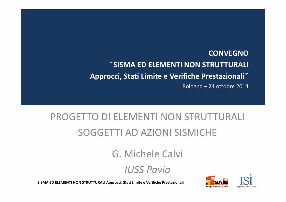
SISMA ED ELEMENTI NON STRUTTURALI Approcci, Stati Limite e Verifiche Prestazionali
CONVEGNO
SISMA ED ELEMENTI NON STRUTTURALI
Approcci, Stati Limite e Verifiche Prestazionali˝
Bologna – 24 ottobre 2014
PROGETTO DI ELEMENTI NON STRUTTURALI
SOGGETTI AD AZIONI SISMICHE
G. Michele Calvi
IUSS Pavia
SISMA ED ELEMENTI NON STRUTTURALI Approcci, Stati Limite e Verifiche Prestazionali
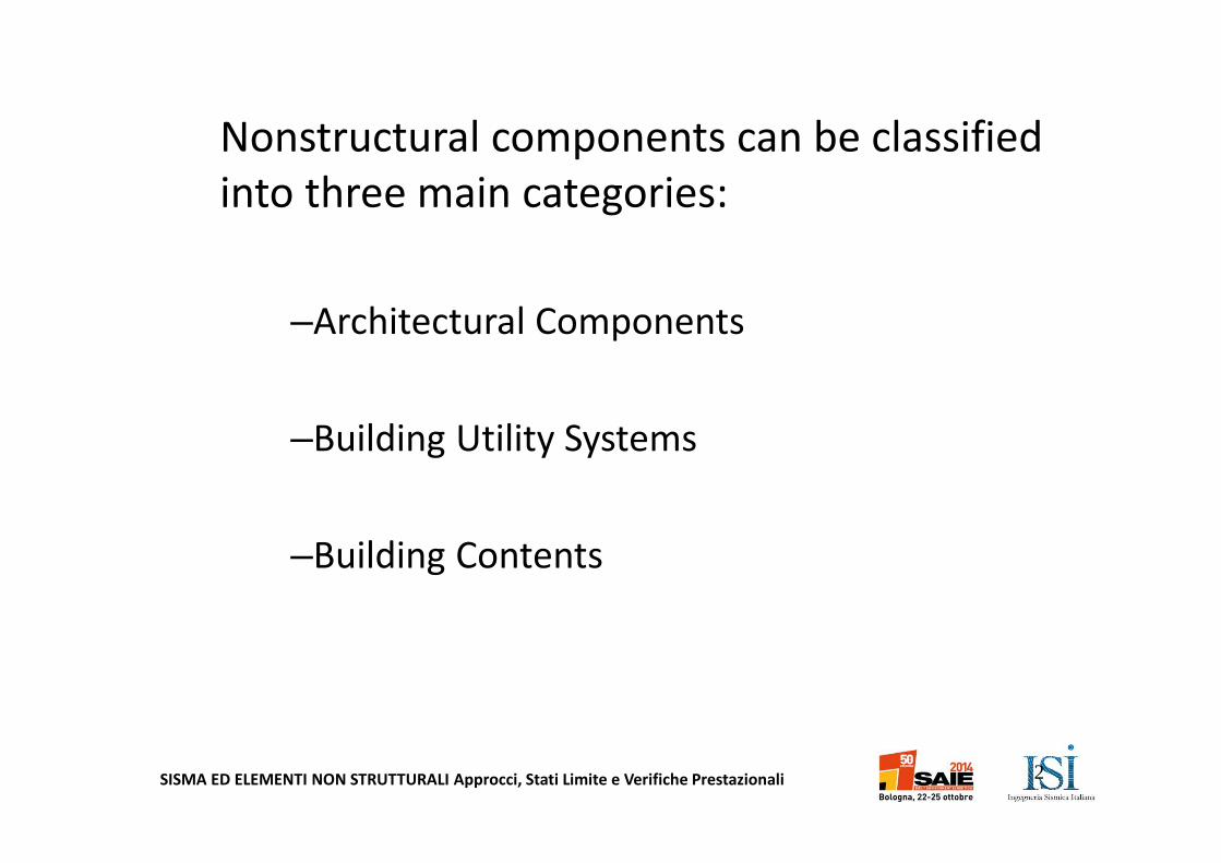
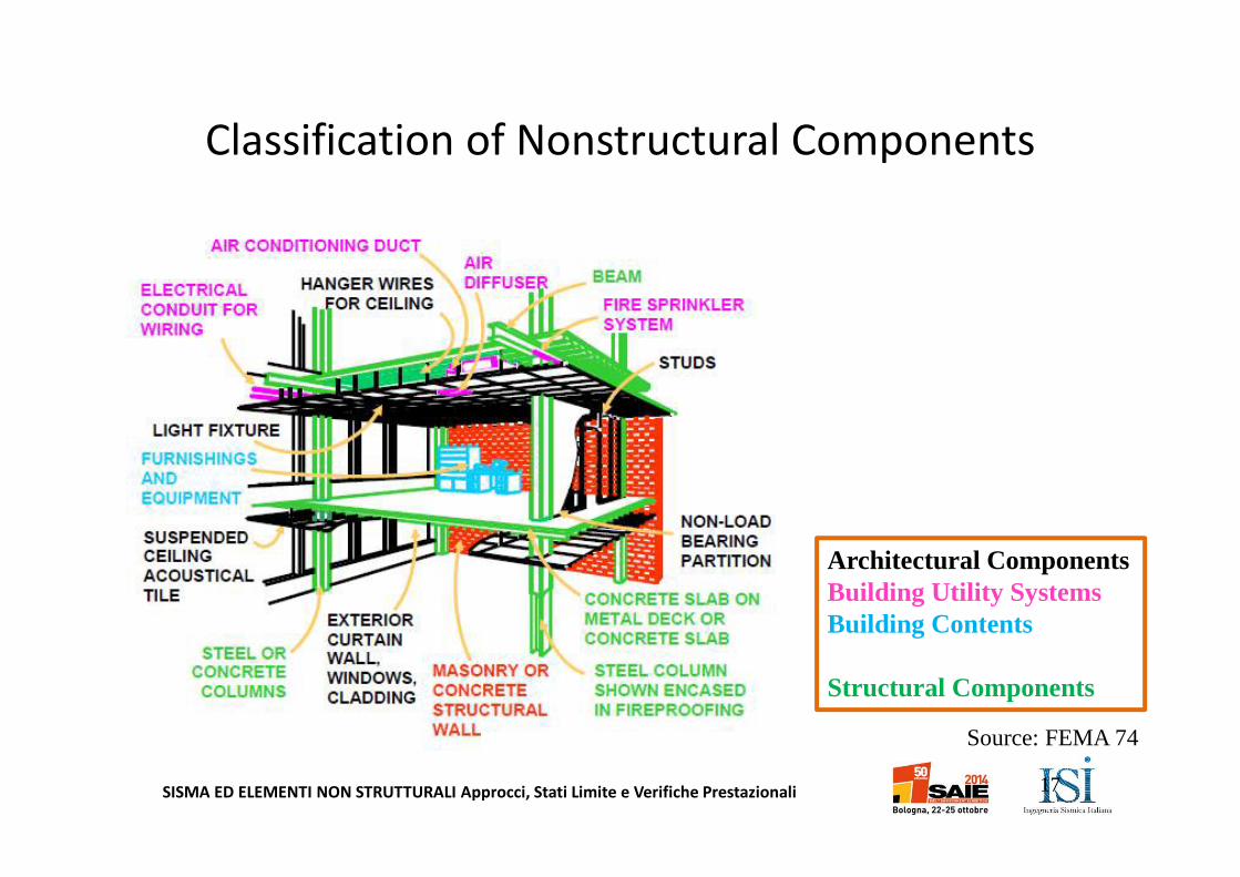
Nonstructural components can be classified
into three main categories:
–Architectural Components
–Building Utility Systems
–Building Contents
2
SISMA ED ELEMENTI NON STRUTTURALI Approcci, Stati Limite e Verifiche Prestazionali
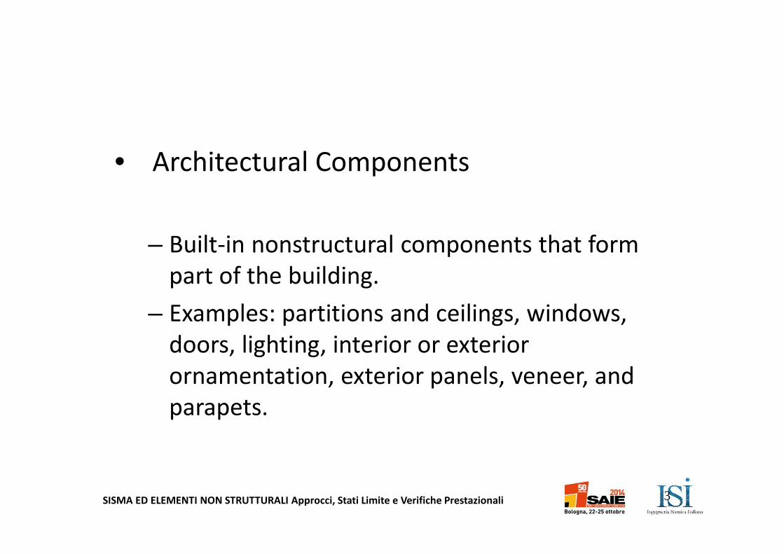
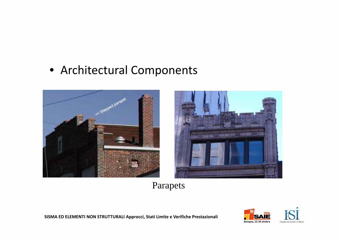
• Architectural Components
– Built-in nonstructural components that form
part of the building.
– Examples: partitions and ceilings, windows,
doors, lighting, interior or exterior
ornamentation, exterior panels, veneer, and
parapets.
3
SISMA ED ELEMENTI NON STRUTTURALI Approcci, Stati Limite e Verifiche Prestazionali
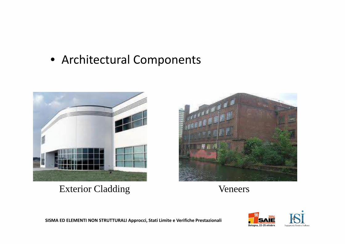
• Architectural Components
4
Exterior Cladding Veneers
SISMA ED ELEMENTI NON STRUTTURALI Approcci, Stati Limite e Verifiche Prestazionali
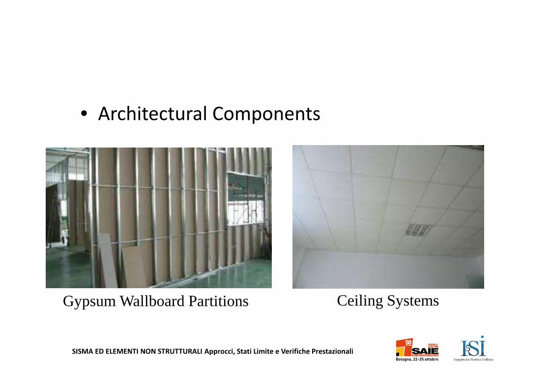
• Architectural Components
5
Gypsum Wallboard Partitions Ceiling Systems
SISMA ED ELEMENTI NON STRUTTURALI Approcci, Stati Limite e Verifiche Prestazionali
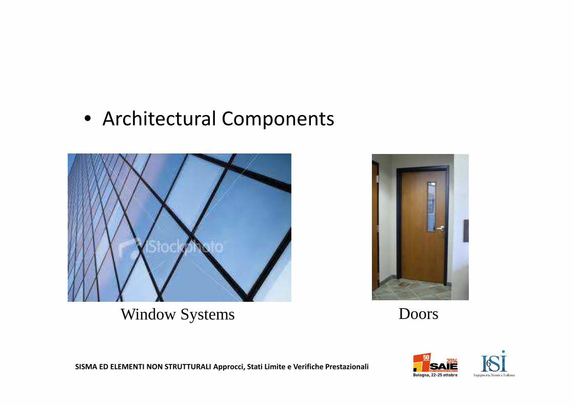
• Architectural Components
6
Window Systems Doors
SISMA ED ELEMENTI NON STRUTTURALI Approcci, Stati Limite e Verifiche Prestazionali
• Architectural Components
7
Parapets
SISMA ED ELEMENTI NON STRUTTURALI Approcci, Stati Limite e Verifiche Prestazionali
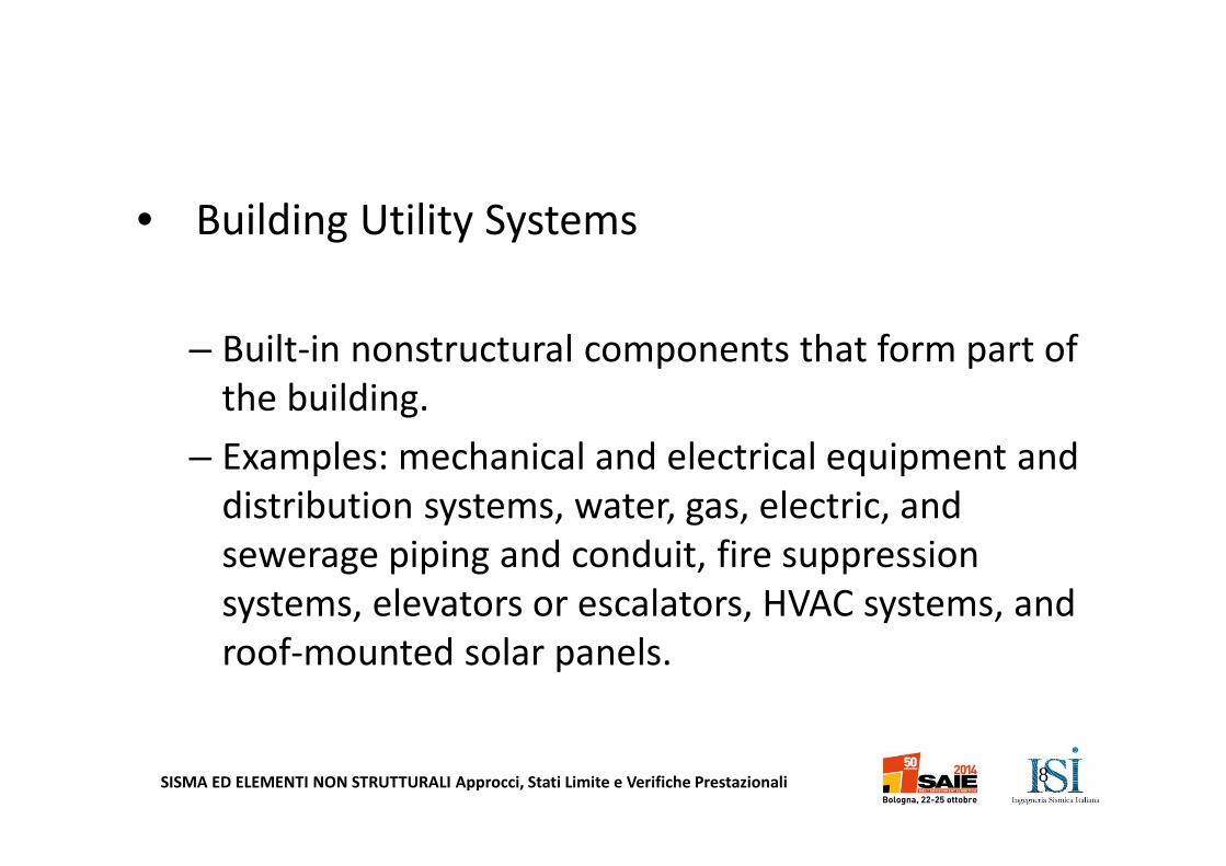
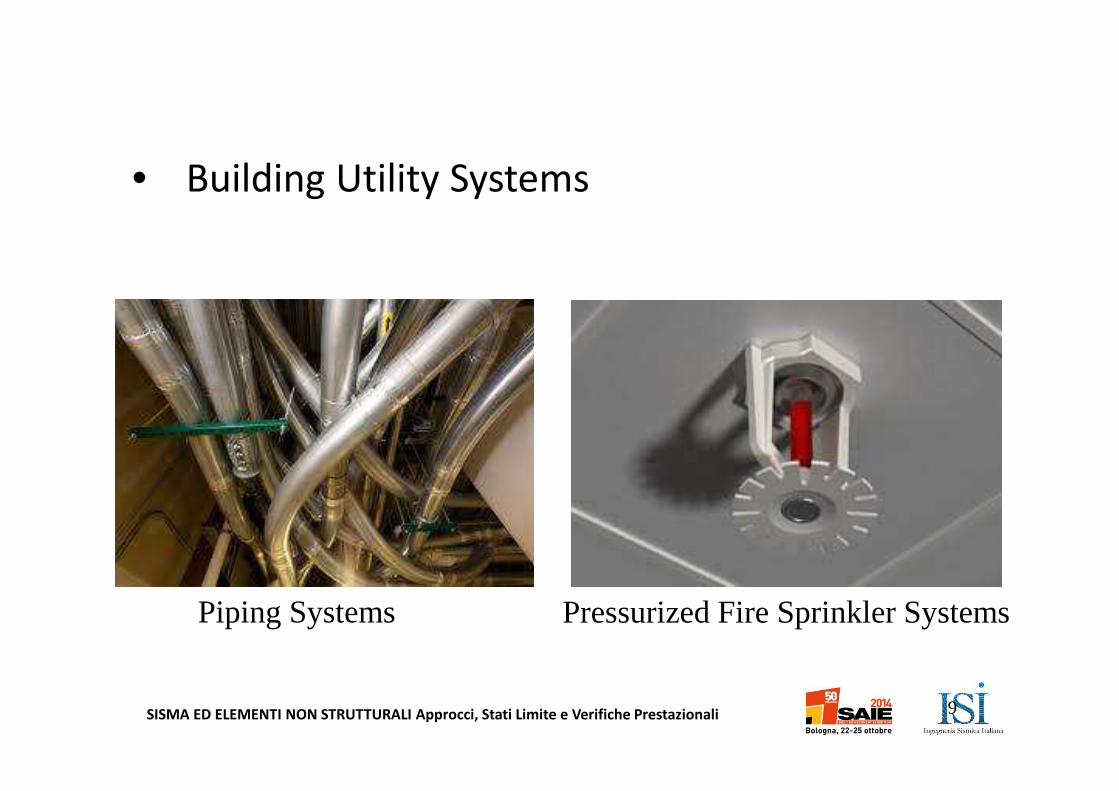
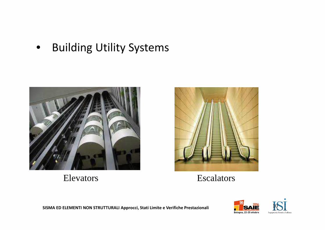
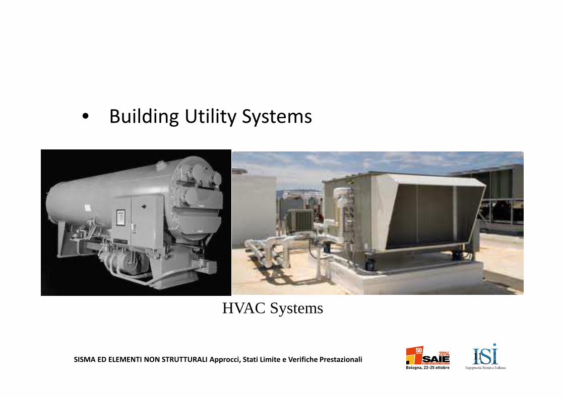
• Building Utility Systems
– Built-in nonstructural components that form part of
the building.
– Examples: mechanical and electrical equipment and
distribution systems, water, gas, electric, and
sewerage piping and conduit, fire suppression
systems, elevators or escalators, HVAC systems, and
roof-mounted solar panels.
8
SISMA ED ELEMENTI NON STRUTTURALI Approcci, Stati Limite e Verifiche Prestazionali
• Building Utility Systems
9
Piping Systems Pressurized Fire Sprinkler Systems
SISMA ED ELEMENTI NON STRUTTURALI Approcci, Stati Limite e Verifiche Prestazionali
• Building Utility Systems
10
Elevators Escalators
SISMA ED ELEMENTI NON STRUTTURALI Approcci, Stati Limite e Verifiche Prestazionali
• Building Utility Systems
11
HVAC Systems
SISMA ED ELEMENTI NON STRUTTURALI Approcci, Stati Limite e Verifiche Prestazionali
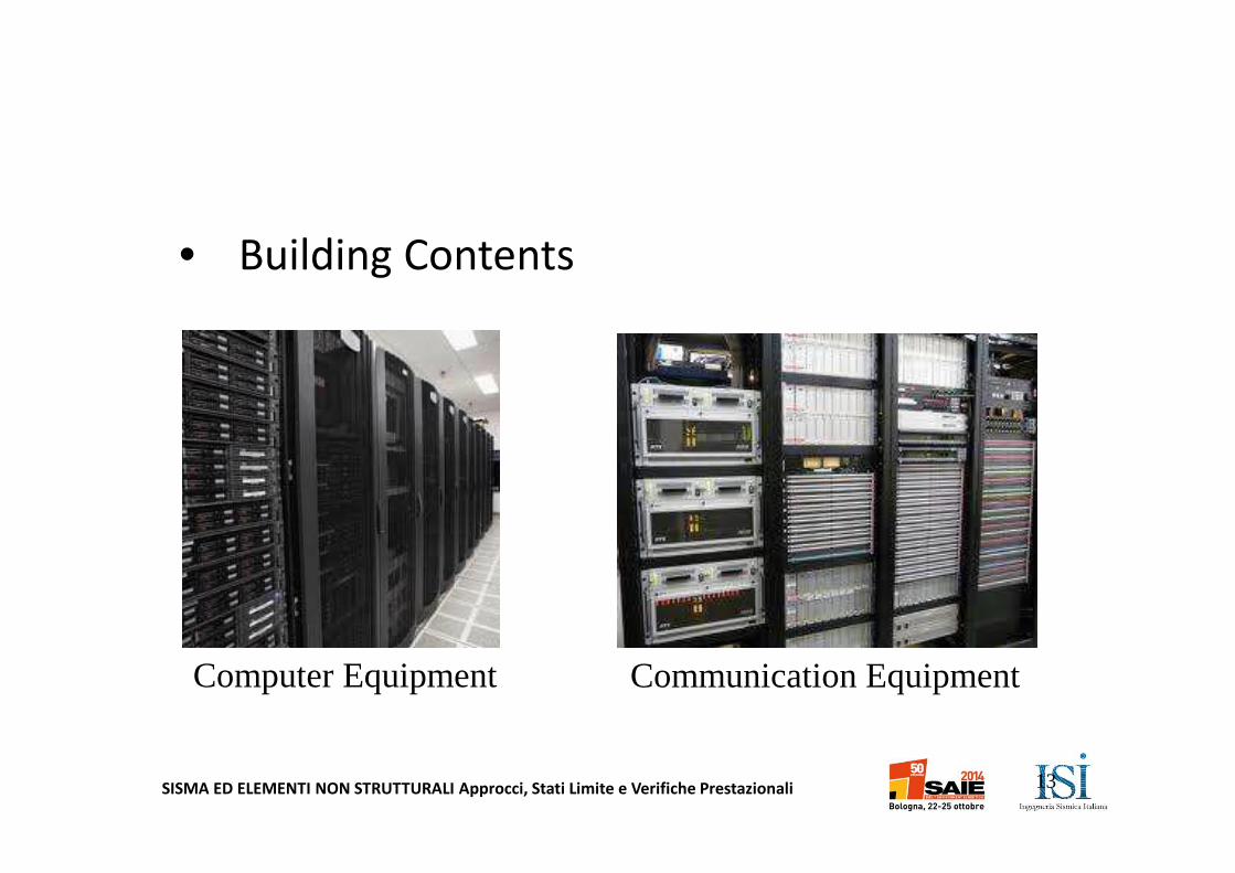
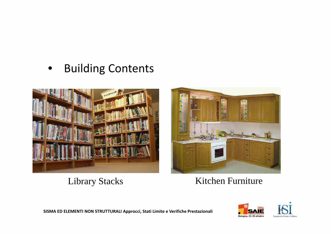
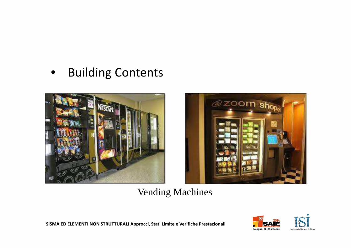
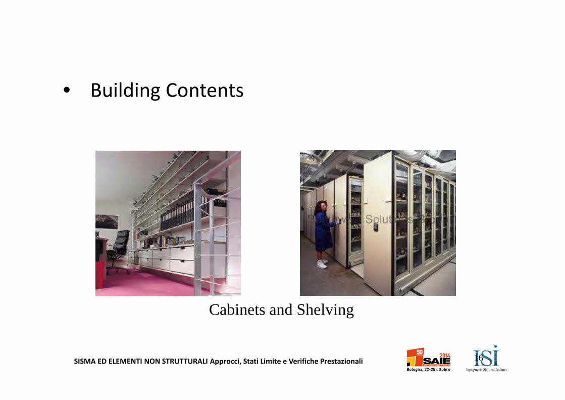
• Building Contents
– Nonstructural components belonging to tenants or occupants.
– Examples: computer and communications equipment; cabinets and shelving for record and supply storage; library stacks; kitchen and laundry facilities; furniture; movable partitions; lockers; and vending machines.
– Judgment needed to identify critical items in a particular building.
12
SISMA ED ELEMENTI NON STRUTTURALI Approcci, Stati Limite e Verifiche Prestazionali
• Building Contents
13
Computer Equipment Communication Equipment
SISMA ED ELEMENTI NON STRUTTURALI Approcci, Stati Limite e Verifiche Prestazionali
• Building Contents
14
Library Stacks Kitchen Furniture
SISMA ED ELEMENTI NON STRUTTURALI Approcci, Stati Limite e Verifiche Prestazionali
• Building Contents
15
Vending Machines
SISMA ED ELEMENTI NON STRUTTURALI Approcci, Stati Limite e Verifiche Prestazionali
• Building Contents
16
Cabinets and Shelving
SISMA ED ELEMENTI NON STRUTTURALI Approcci, Stati Limite e Verifiche Prestazionali 17
Source: FEMA 74
Classification of Nonstructural Components
Architectural ComponentsBuilding Utility SystemsBuilding Contents
Structural Components
SISMA ED ELEMENTI NON STRUTTURALI Approcci, Stati Limite e Verifiche Prestazionali18
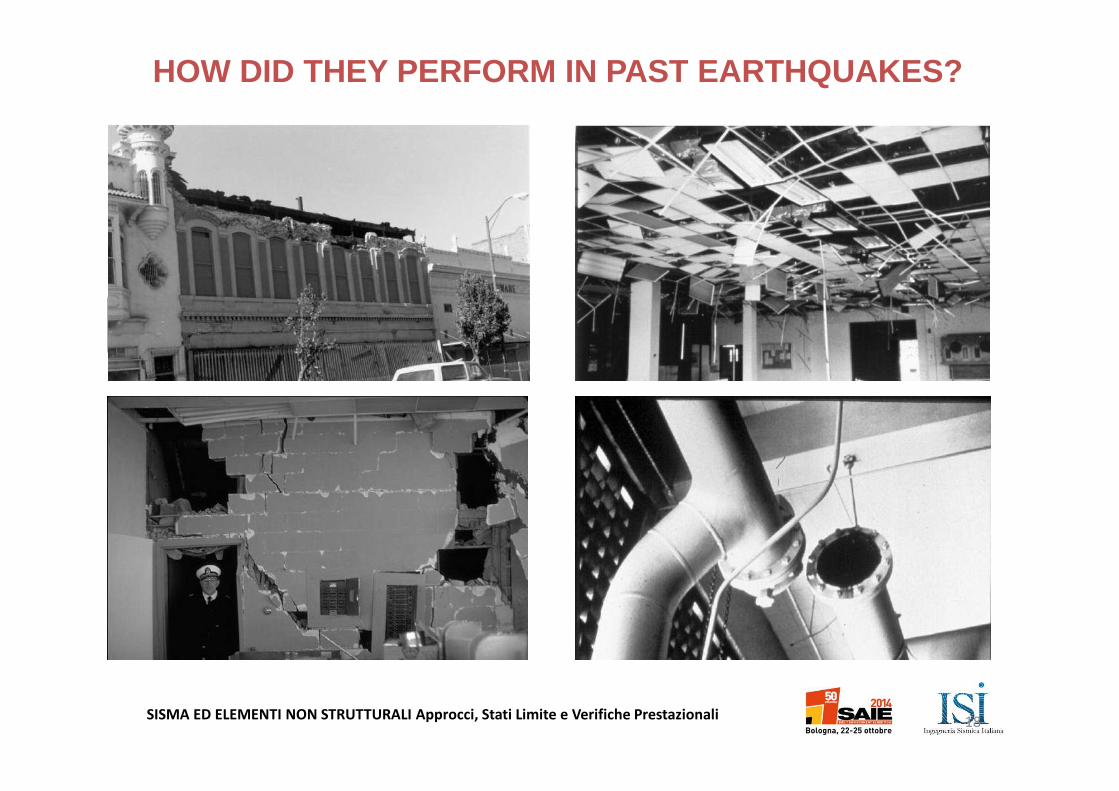
HOW DID THEY PERFORM IN PAST EARTHQUAKES?
SISMA ED ELEMENTI NON STRUTTURALI Approcci, Stati Limite e Verifiche Prestazionali
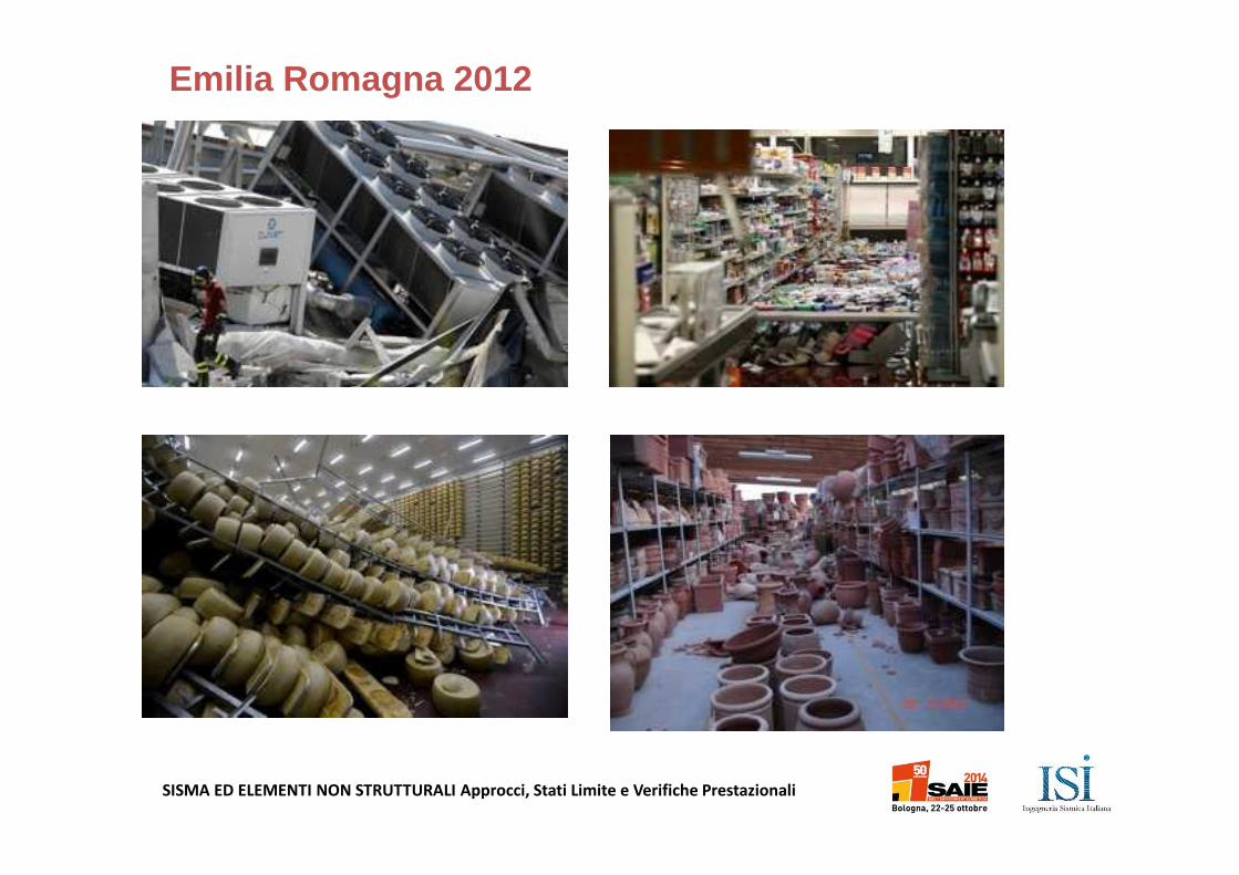
Emilia Romagna 2012
SISMA ED ELEMENTI NON STRUTTURALI Approcci, Stati Limite e Verifiche Prestazionali
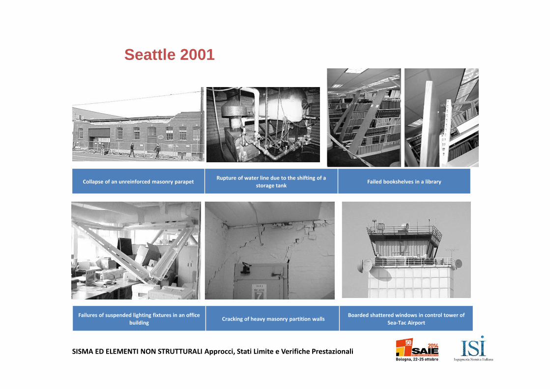
Failures of suspended lighting fixtures in an office
buildingCracking of heavy masonry partition walls
Boarded shattered windows in control tower of
Sea-Tac Airport
Collapse of an unreinforced masonry parapetRupture of water line due to the shifting of a
storage tankFailed bookshelves in a library
Seattle 2001
SISMA ED ELEMENTI NON STRUTTURALI Approcci, Stati Limite e Verifiche Prestazionali
SISMA ED ELEMENTI NON STRUTTURALI Approcci, Stati Limite e Verifiche Prestazionali
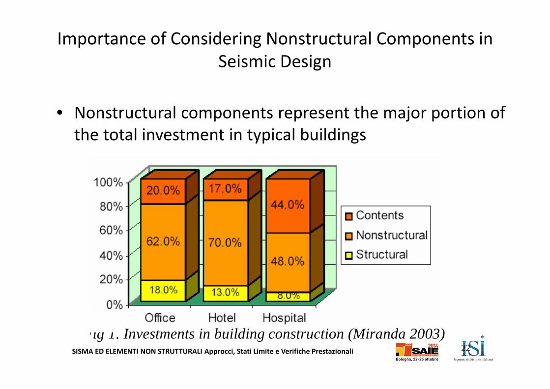
• Nonstructural components represent the major portion of
the total investment in typical buildings
Importance of Considering Nonstructural Components in
Seismic Design
22Fig 1. Investments in building construction (Miranda 2003)
SISMA ED ELEMENTI NON STRUTTURALI Approcci, Stati Limite e Verifiche Prestazionali
• Damage to nonstructural components occurs at seismic
intensities much lower than those required to produce
structural damage
– Steel moment-resisting frames yield at story drifts beyond 1%
while gypsum partition walls show significant crack at drifts as
low as 0.25%
– In many past earthquakes, losses from damage to nonstructural
building components have exceeded losses from structural
damage.
23
SISMA ED ELEMENTI NON STRUTTURALI Approcci, Stati Limite e Verifiche Prestazionali24
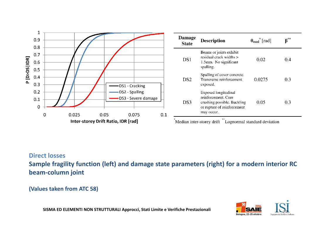
Direct losses
Sample fragility function (left) and damage state parameters (right) for a modern interior RC
beam-column joint
(Values taken from ATC 58)
SISMA ED ELEMENTI NON STRUTTURALI Approcci, Stati Limite e Verifiche Prestazionali
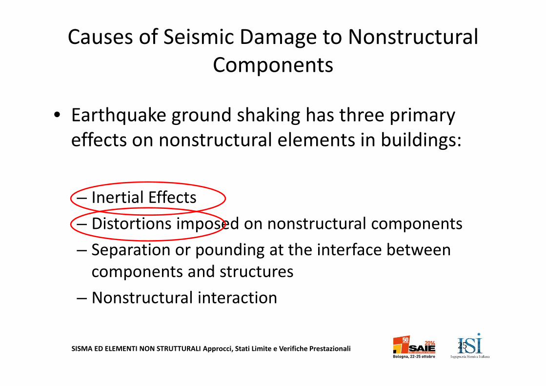
Causes of Seismic Damage to Nonstructural
Components
• Earthquake ground shaking has three primary
effects on nonstructural elements in buildings:
– Inertial Effects
– Distortions imposed on nonstructural components
– Separation or pounding at the interface between
components and structures
– Nonstructural interaction
25
SISMA ED ELEMENTI NON STRUTTURALI Approcci, Stati Limite e Verifiche Prestazionali26
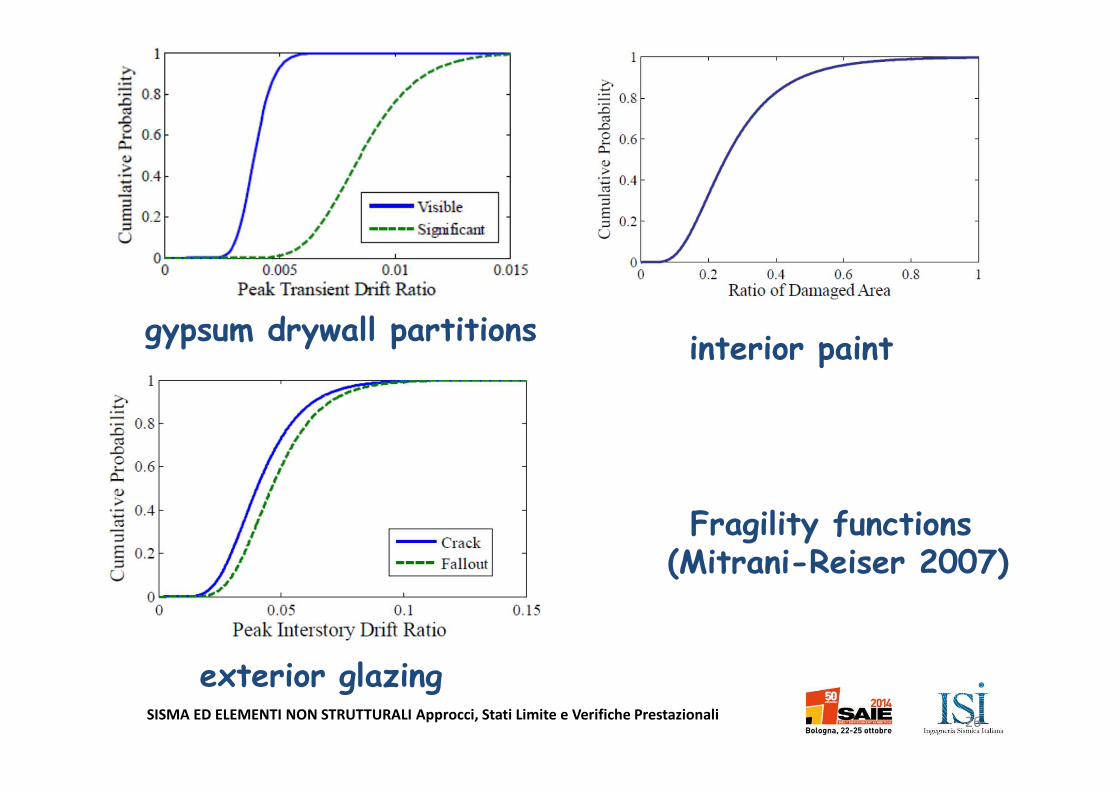
gypsum drywall partitions
exterior glazing
Fragility functions (Mitrani-Reiser 2007)
interior paint
SISMA ED ELEMENTI NON STRUTTURALI Approcci, Stati Limite e Verifiche Prestazionali27
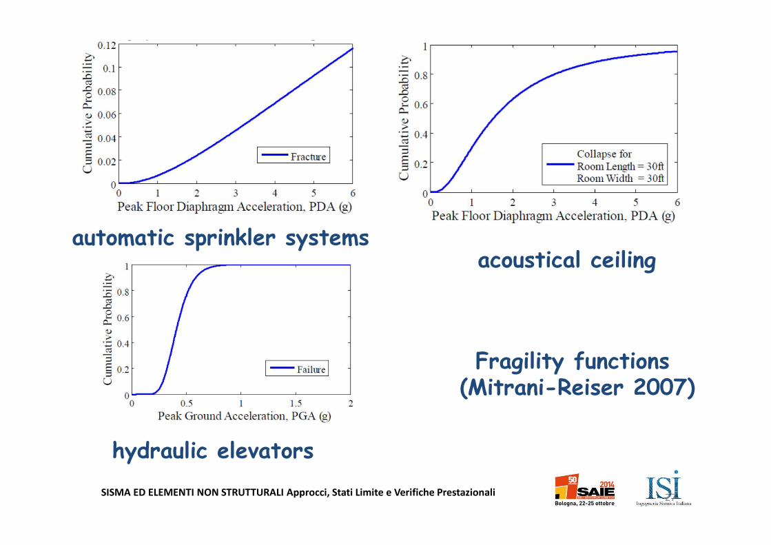
acoustical ceilingautomatic sprinkler systems
hydraulic elevators
Fragility functions (Mitrani-Reiser 2007)
SISMA ED ELEMENTI NON STRUTTURALI Approcci, Stati Limite e Verifiche Prestazionali28
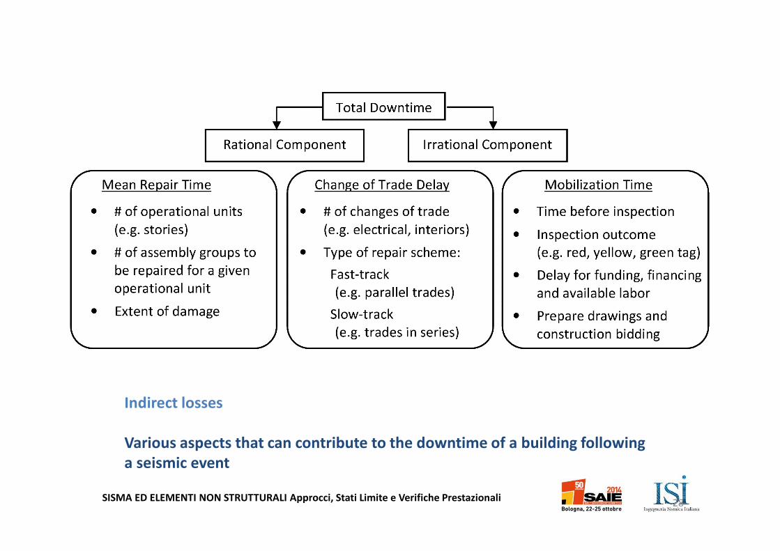
Indirect losses
Various aspects that can contribute to the downtime of a building following
a seismic event

SISMA ED ELEMENTI NON STRUTTURALI Approcci, Stati Limite e Verifiche Prestazionali
Analysis Methods
• Direct Analysis Method– Complete modeling of structural and nonstructural
components
– Ground input motions
• Cascading Analysis Method – Uncoupled analyses of structural and nonstructural
components
– Dynamic properties and floor responses of the primary structure are first estimated neglecting interaction with the nonstructural components
– Structural response at the attachment level is then considered as the input motion for the estimation of the response of the nonstructural component.
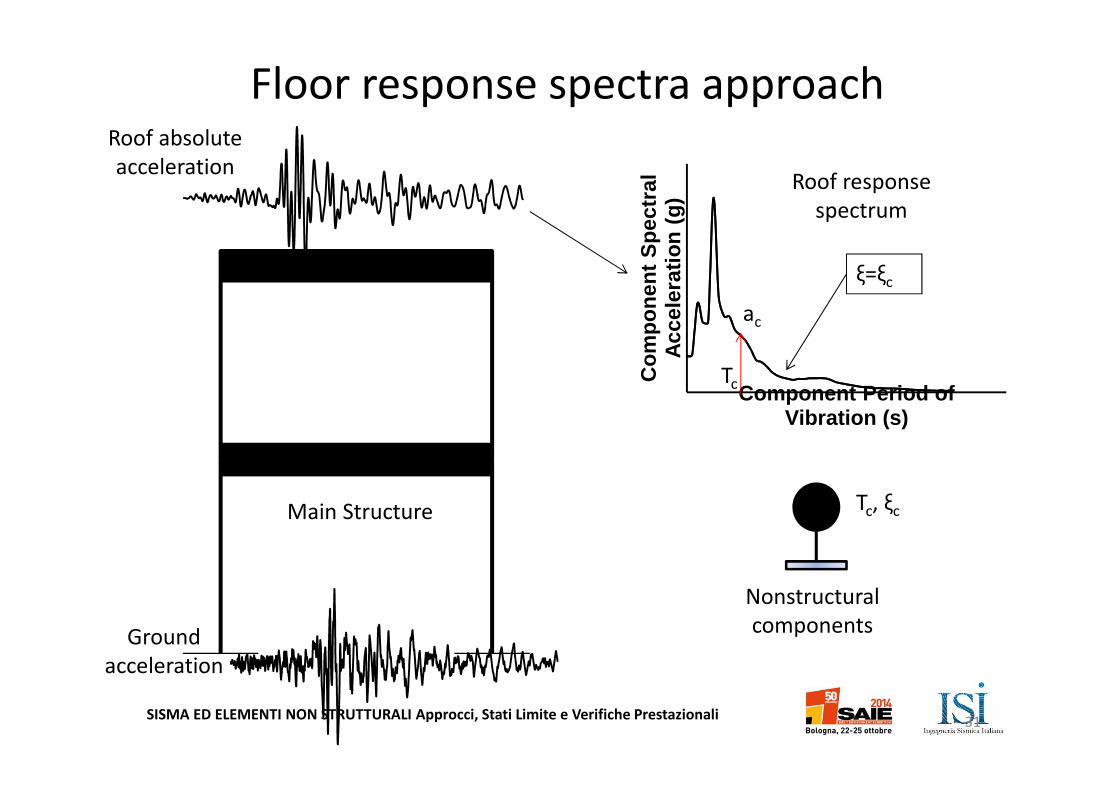
– Most popular cascading approach: Floor Response Spectrum (FRS) Method
29
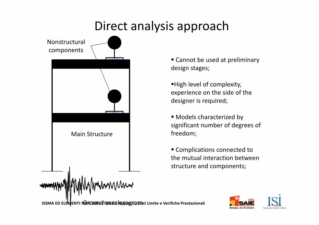
SISMA ED ELEMENTI NON STRUTTURALI Approcci, Stati Limite e Verifiche PrestazionaliGround accelerogram
Nonstructural
components
Main Structure
� Cannot be used at preliminary
design stages;
�High level of complexity,
experience on the side of the
designer is required;
� Models characterized by
significant number of degrees of
freedom;
� Complications connected to
the mutual interaction between
structure and components;
Direct analysis approach
30
SISMA ED ELEMENTI NON STRUTTURALI Approcci, Stati Limite e Verifiche Prestazionali
Tc, ξc
Roof absolute
acceleration
Ground
acceleration
Nonstructural
components
Main Structure
Co
mp
on
ent
Sp
ectr
al
Acc
eler
atio
n (
g)
Component Period of Vibration (s)
ac
Roof response
spectrum
Tc
ξ=ξc
Floor response spectra approach
31
SISMA ED ELEMENTI NON STRUTTURALI Approcci, Stati Limite e Verifiche Prestazionali
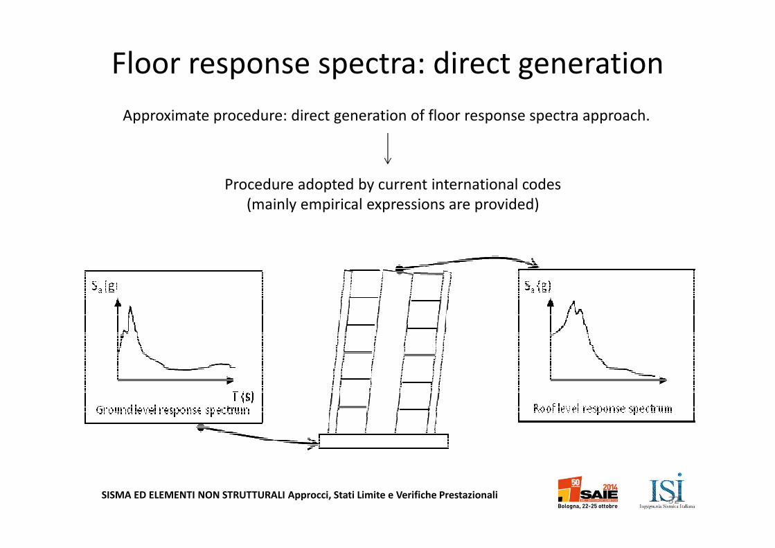
Approximate procedure: direct generation of floor response spectra approach.
Floor response spectra: direct generation
Procedure adopted by current international codes
(mainly empirical expressions are provided)
32
SISMA ED ELEMENTI NON STRUTTURALI Approcci, Stati Limite e Verifiche Prestazionali
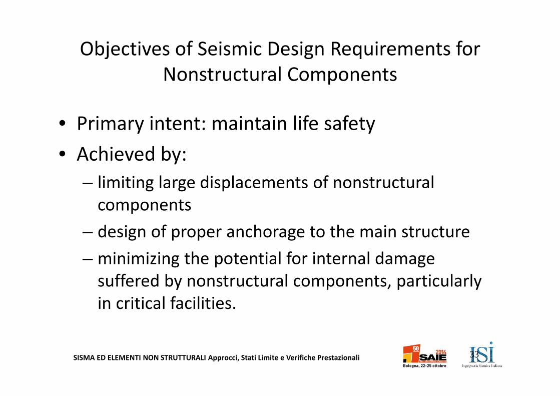
Objectives of Seismic Design Requirements for
Nonstructural Components
• Primary intent: maintain life safety
• Achieved by:
– limiting large displacements of nonstructural
components
– design of proper anchorage to the main structure
– minimizing the potential for internal damage
suffered by nonstructural components, particularly
in critical facilities.
33
SISMA ED ELEMENTI NON STRUTTURALI Approcci, Stati Limite e Verifiche Prestazionali
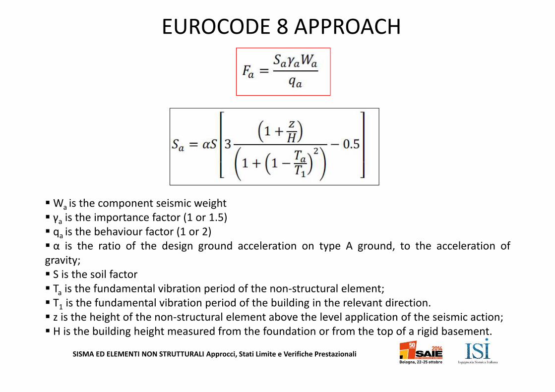
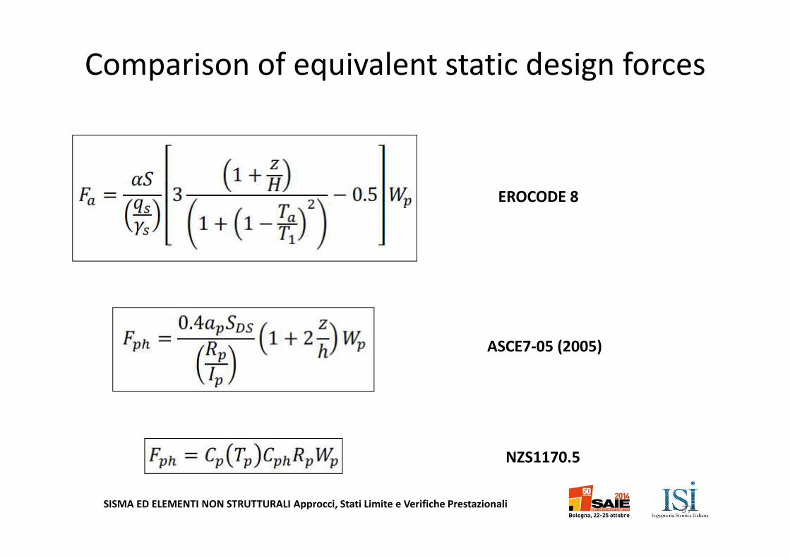
EUROCODE 8 APPROACH
� Wa is the component seismic weight
� γa is the importance factor (1 or 1.5)
� qa is the behaviour factor (1 or 2)
� α is the ratio of the design ground acceleration on type A ground, to the acceleration of
gravity;
� S is the soil factor
� Ta is the fundamental vibration period of the non-structural element;
� T1 is the fundamental vibration period of the building in the relevant direction.
� z is the height of the non-structural element above the level application of the seismic action;
� H is the building height measured from the foundation or from the top of a rigid basement.
SISMA ED ELEMENTI NON STRUTTURALI Approcci, Stati Limite e Verifiche Prestazionali
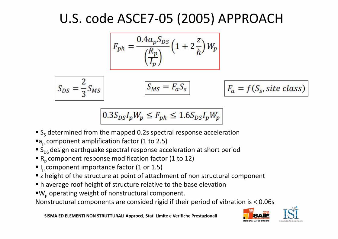
U.S. code ASCE7-05 (2005) APPROACH
� SS determined from the mapped 0.2s spectral response acceleration
�ap component amplification factor (1 to 2.5)
� SDS design earthquake spectral response acceleration at short period
� Rp component response modification factor (1 to 12)
� Ip component importance factor (1 or 1.5)
� z height of the structure at point of attachment of non structural component
� h average roof height of structure relative to the base elevation
�Wp operating weight of nonstructural component.
Nonstructural components are consided rigid if their period of vibration is < 0.06s35
SISMA ED ELEMENTI NON STRUTTURALI Approcci, Stati Limite e Verifiche Prestazionali
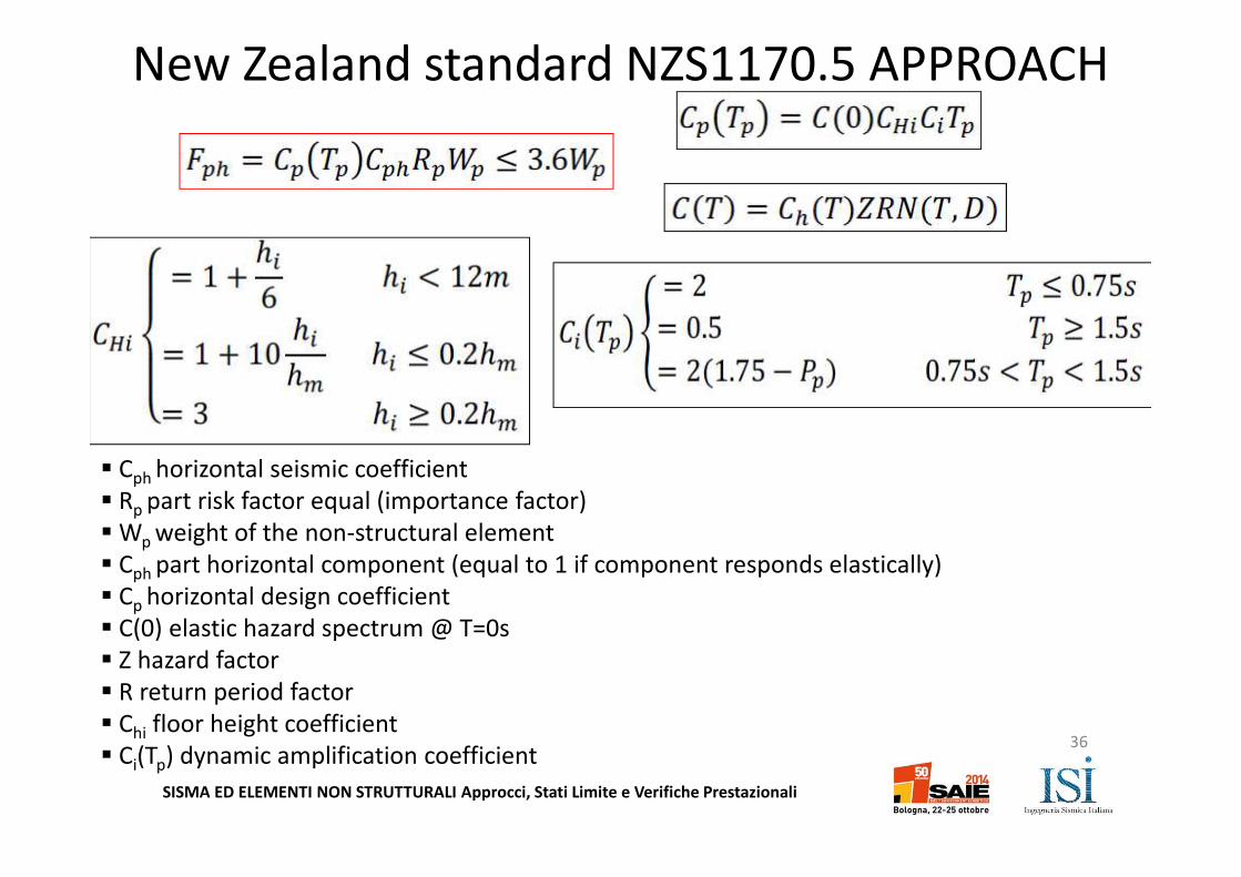
New Zealand standard NZS1170.5 APPROACH
� Cph horizontal seismic coefficient
� Rp part risk factor equal (importance factor)
� Wp weight of the non-structural element
� Cph part horizontal component (equal to 1 if component responds elastically)
� Cp horizontal design coefficient
� C(0) elastic hazard spectrum @ T=0s
� Z hazard factor
� R return period factor
� Chi floor height coefficient
� Ci(Tp) dynamic amplification coefficient36
SISMA ED ELEMENTI NON STRUTTURALI Approcci, Stati Limite e Verifiche Prestazionali
Comparison of equivalent static design forces
EROCODE 8
ASCE7-05 (2005)
NZS1170.5
37
SISMA ED ELEMENTI NON STRUTTURALI Approcci, Stati Limite e Verifiche Prestazionali
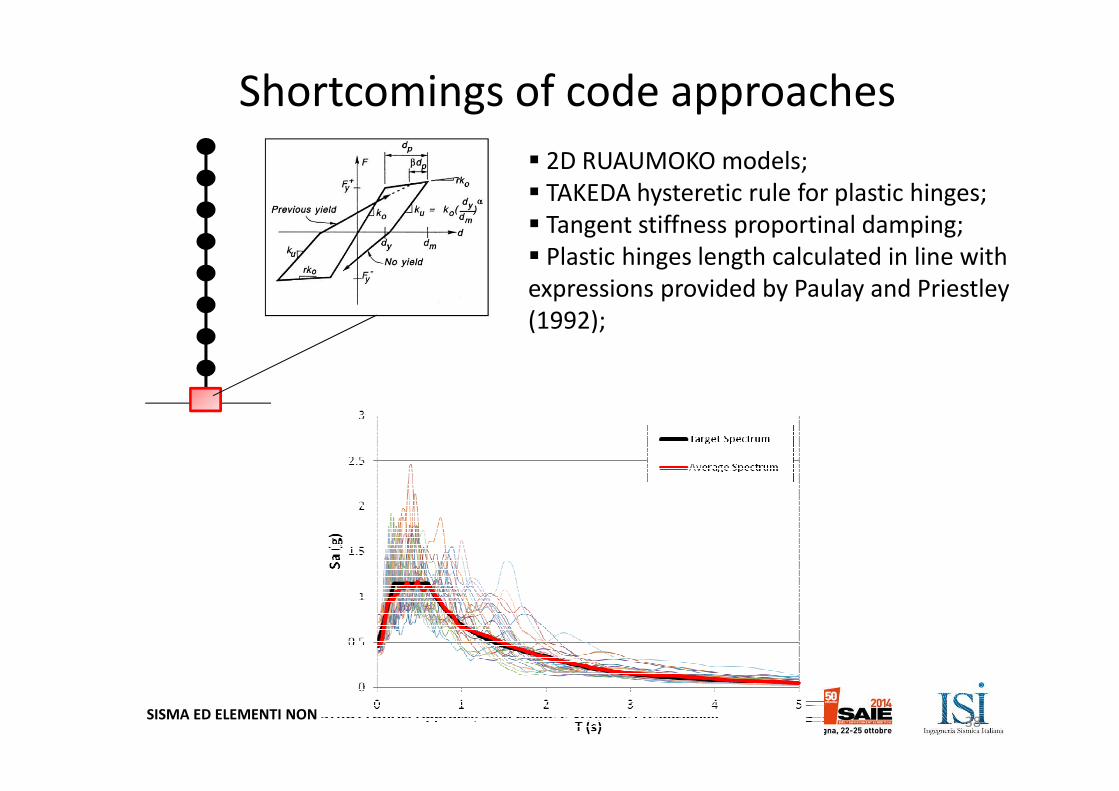
� 2D RUAUMOKO models;
� TAKEDA hysteretic rule for plastic hinges;
� Tangent stiffness proportinal damping;
� Plastic hinges length calculated in line with
expressions provided by Paulay and Priestley
(1992);
Shortcomings of code approaches
38
SISMA ED ELEMENTI NON STRUTTURALI Approcci, Stati Limite e Verifiche Prestazionali
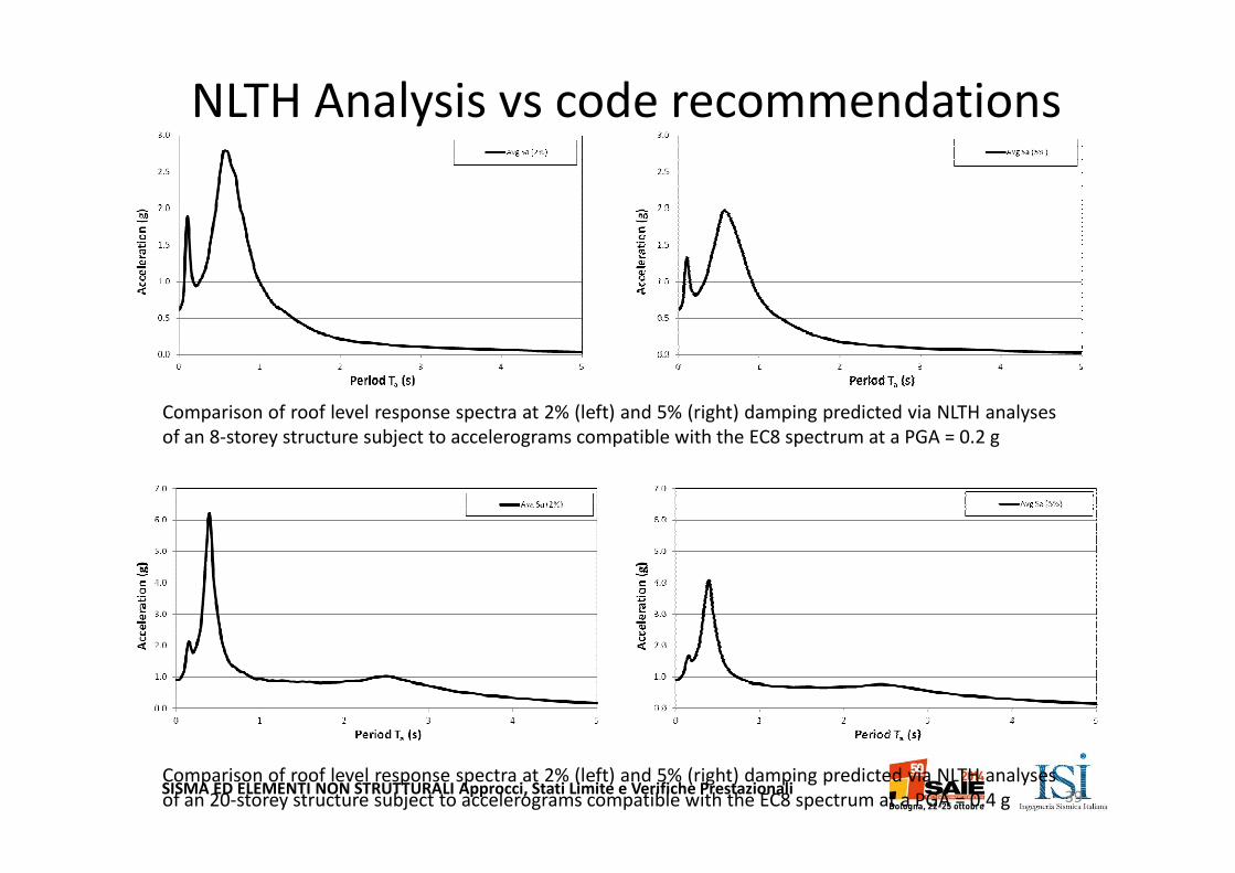
Comparison of roof level response spectra at 2% (left) and 5% (right) damping predicted via NLTH analyses
of an 8-storey structure subject to accelerograms compatible with the EC8 spectrum at a PGA = 0.2 g
Comparison of roof level response spectra at 2% (left) and 5% (right) damping predicted via NLTH analyses
of an 20-storey structure subject to accelerograms compatible with the EC8 spectrum at a PGA = 0.4 g
NLTH Analysis vs code recommendations
39
SISMA ED ELEMENTI NON STRUTTURALI Approcci, Stati Limite e Verifiche Prestazionali
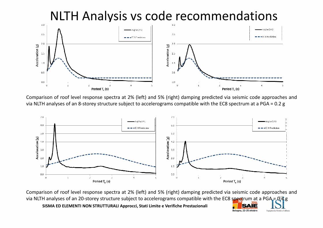
Comparison of roof level response spectra at 2% (left) and 5% (right) damping predicted via seismic code approaches and
via NLTH analyses of an 8-storey structure subject to accelerograms compatible with the EC8 spectrum at a PGA = 0.2 g
Comparison of roof level response spectra at 2% (left) and 5% (right) damping predicted via seismic code approaches and
via NLTH analyses of an 20-storey structure subject to accelerograms compatible with the EC8 spectrum at a PGA = 0.4 g
NLTH Analysis vs code recommendations
40
SISMA ED ELEMENTI NON STRUTTURALI Approcci, Stati Limite e Verifiche Prestazionali
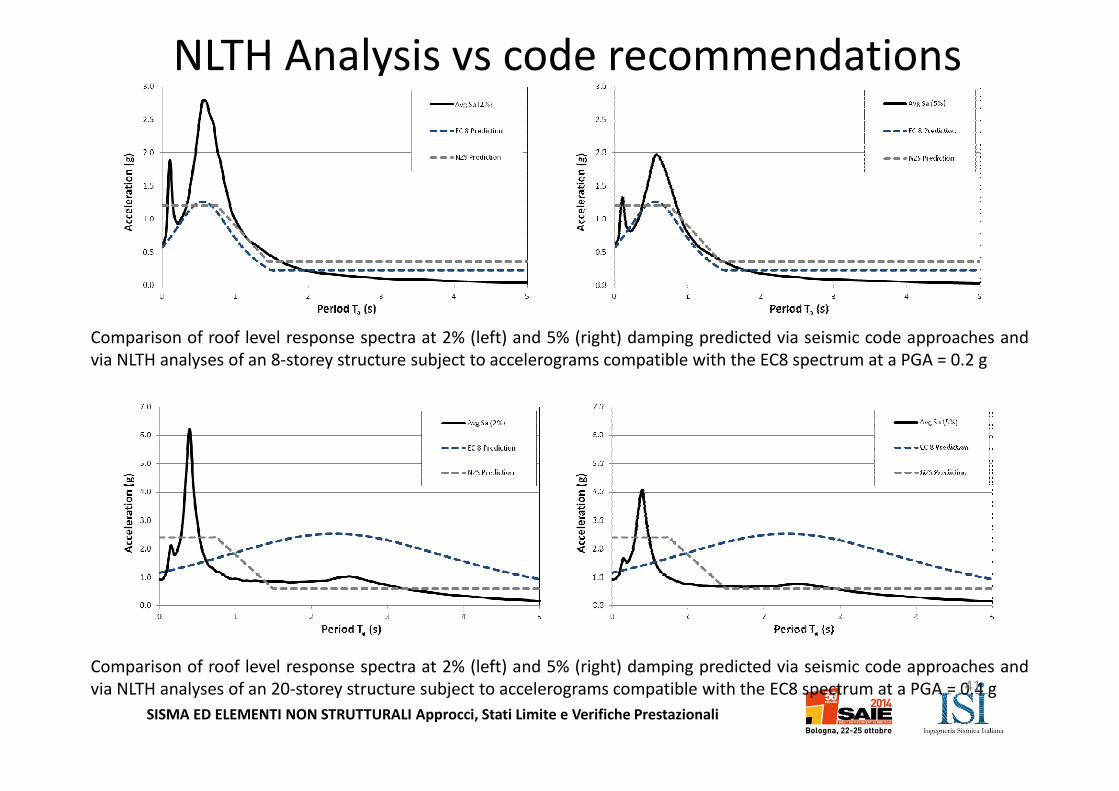
Comparison of roof level response spectra at 2% (left) and 5% (right) damping predicted via seismic code approaches and
via NLTH analyses of an 8-storey structure subject to accelerograms compatible with the EC8 spectrum at a PGA = 0.2 g
Comparison of roof level response spectra at 2% (left) and 5% (right) damping predicted via seismic code approaches and
via NLTH analyses of an 20-storey structure subject to accelerograms compatible with the EC8 spectrum at a PGA = 0.4 g
NLTH Analysis vs code recommendations
41
SISMA ED ELEMENTI NON STRUTTURALI Approcci, Stati Limite e Verifiche Prestazionali
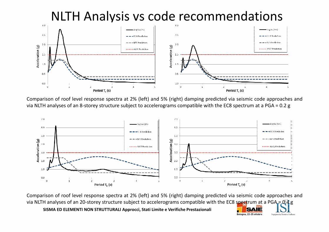
Comparison of roof level response spectra at 2% (left) and 5% (right) damping predicted via seismic code approaches and
via NLTH analyses of an 8-storey structure subject to accelerograms compatible with the EC8 spectrum at a PGA = 0.2 g
Comparison of roof level response spectra at 2% (left) and 5% (right) damping predicted via seismic code approaches and
via NLTH analyses of an 20-storey structure subject to accelerograms compatible with the EC8 spectrum at a PGA = 0.4 g
NLTH Analysis vs code recommendations
42
SISMA ED ELEMENTI NON STRUTTURALI Approcci, Stati Limite e Verifiche Prestazionali
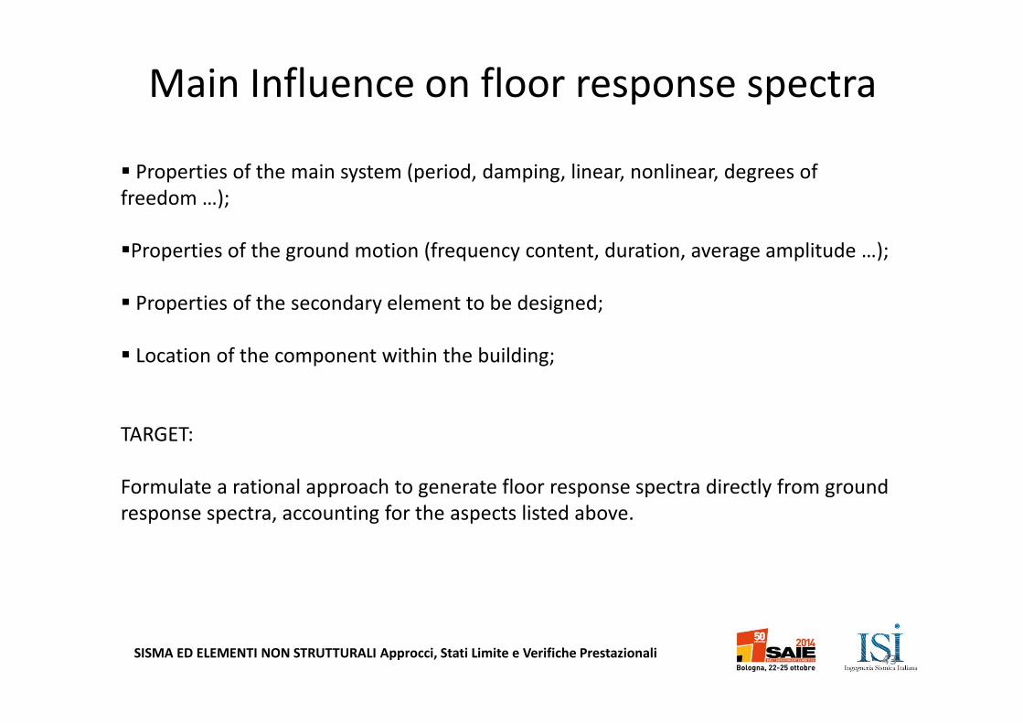
� Properties of the main system (period, damping, linear, nonlinear, degrees of
freedom …);
�Properties of the ground motion (frequency content, duration, average amplitude …);
� Properties of the secondary element to be designed;
� Location of the component within the building;
TARGET:
Formulate a rational approach to generate floor response spectra directly from ground
response spectra, accounting for the aspects listed above.
Main Influence on floor response spectra
43
SISMA ED ELEMENTI NON STRUTTURALI Approcci, Stati Limite e Verifiche Prestazionali
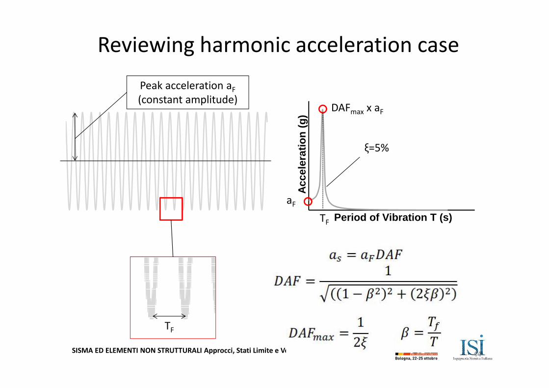
Acc
eler
atio
n (
g)
Period of Vibration T (s)
DAFmax x aF
Peak acceleration aF
(constant amplitude)
TF
ξ=5%
aF
TF
Reviewing harmonic acceleration case
44
SISMA ED ELEMENTI NON STRUTTURALI Approcci, Stati Limite e Verifiche Prestazionali
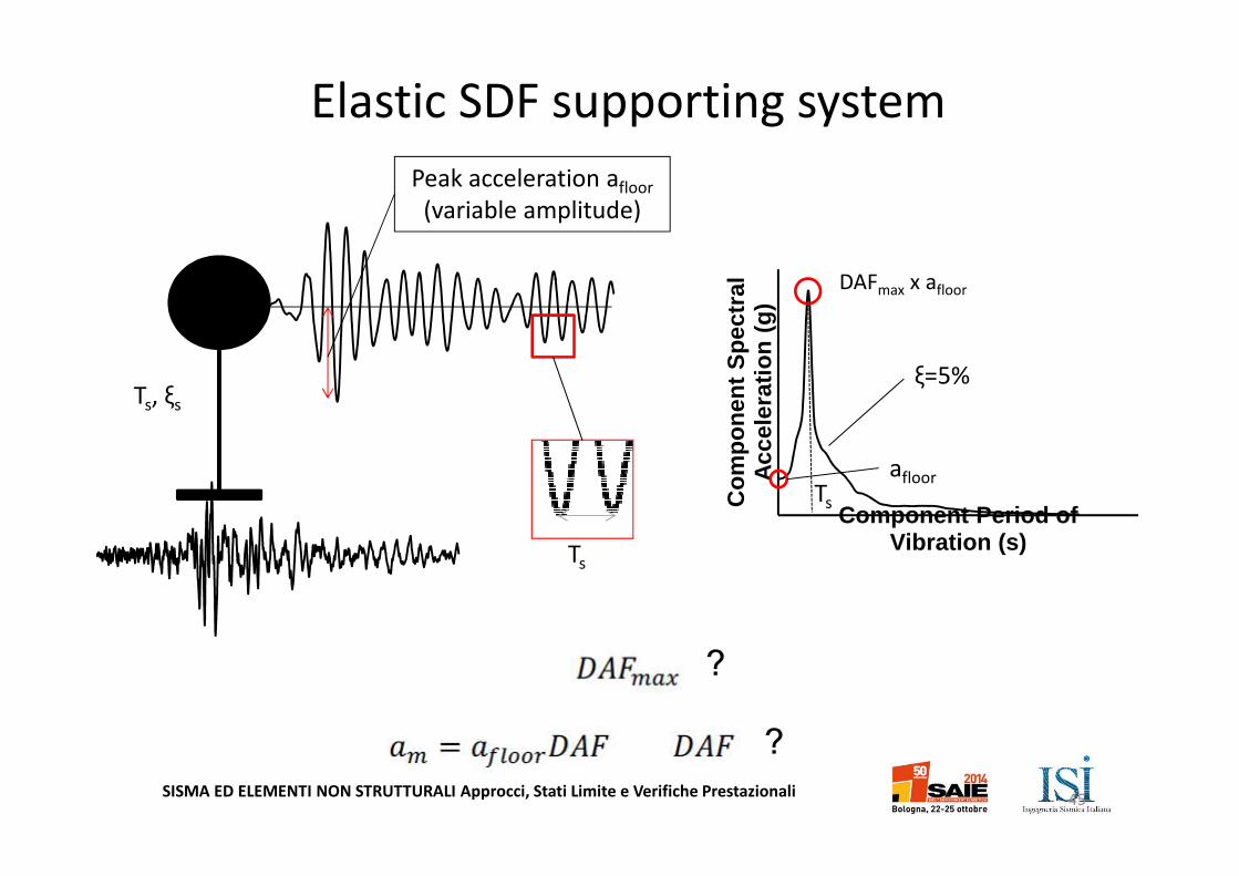
Peak acceleration afloor
(variable amplitude)
Ts, ξs
Ts
Co
mp
on
ent
Sp
ectr
al
Acc
eler
atio
n (
g)
Component Period of Vibration (s)
ξ=5%
Ts
DAFmax x afloor
afloor
Elastic SDF supporting system
?
?
45

SISMA ED ELEMENTI NON STRUTTURALI Approcci, Stati Limite e Verifiche Prestazionali
� Infinite duration;
� Constant amplitude;
� Constant forcing frequency;
� Finite duration;
� Variable amplitude;
� Constant forcing frequency;
Harmonic acceleration theory:
� Acceleration at T=0s properly
estimated;
�Peak of the spectrum is correctly
located on the x-axis but
overestimated in terms of intensity;
� Decrasing branch of the spectrum
drops too quickly
Harmonic acceleration spectrum
Floor response spectrum
Elastic SDF supporting system
46
SISMA ED ELEMENTI NON STRUTTURALI Approcci, Stati Limite e Verifiche Prestazionali
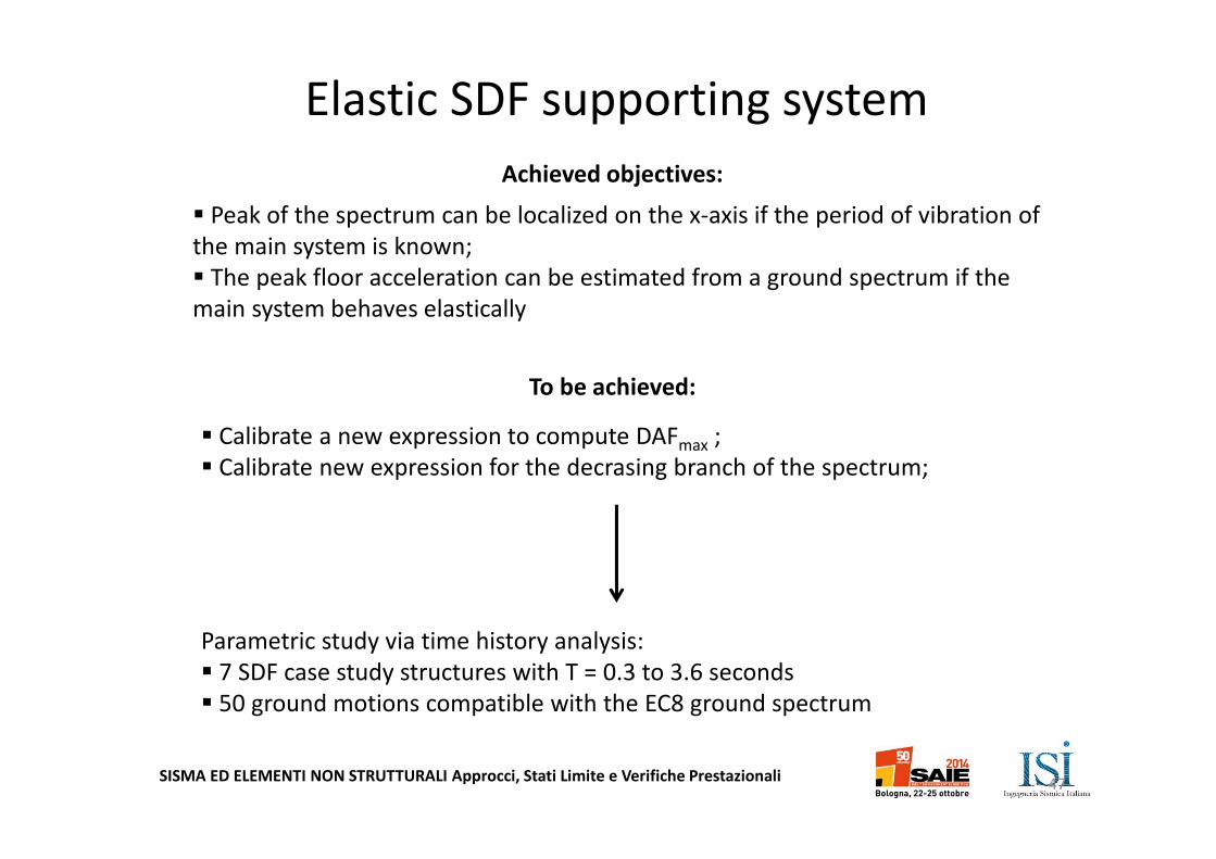
� Peak of the spectrum can be localized on the x-axis if the period of vibration of
the main system is known;
� The peak floor acceleration can be estimated from a ground spectrum if the
main system behaves elastically
� Calibrate a new expression to compute DAFmax ;
� Calibrate new expression for the decrasing branch of the spectrum;
Achieved objectives:
To be achieved:
Parametric study via time history analysis:
� 7 SDF case study structures with T = 0.3 to 3.6 seconds
� 50 ground motions compatible with the EC8 ground spectrum
Elastic SDF supporting system
47
SISMA ED ELEMENTI NON STRUTTURALI Approcci, Stati Limite e Verifiche Prestazionali
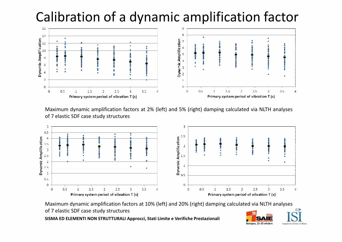
Calibration of a dynamic amplification factor
Maximum dynamic amplification factors at 2% (left) and 5% (right) damping calculated via NLTH analyses
of 7 elastic SDF case study structures
Maximum dynamic amplification factors at 10% (left) and 20% (right) damping calculated via NLTH analyses
of 7 elastic SDF case study structures 48
SISMA ED ELEMENTI NON STRUTTURALI Approcci, Stati Limite e Verifiche Prestazionali
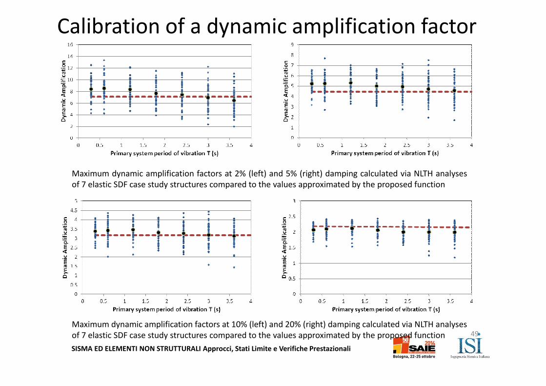
Calibration of a dynamic amplification factor
Maximum dynamic amplification factors at 2% (left) and 5% (right) damping calculated via NLTH analyses
of 7 elastic SDF case study structures compared to the values approximated by the proposed function
Maximum dynamic amplification factors at 10% (left) and 20% (right) damping calculated via NLTH analyses
of 7 elastic SDF case study structures compared to the values approximated by the proposed function 49
SISMA ED ELEMENTI NON STRUTTURALI Approcci, Stati Limite e Verifiche Prestazionali
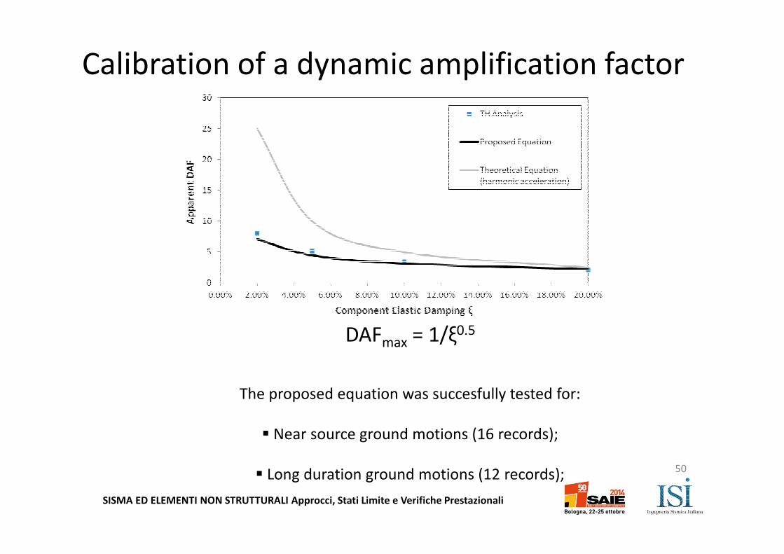
DAFmax = 1/ξ0.5
The proposed equation was succesfully tested for:
� Near source ground motions (16 records);
� Long duration ground motions (12 records);
Calibration of a dynamic amplification factor
50
SISMA ED ELEMENTI NON STRUTTURALI Approcci, Stati Limite e Verifiche Prestazionali
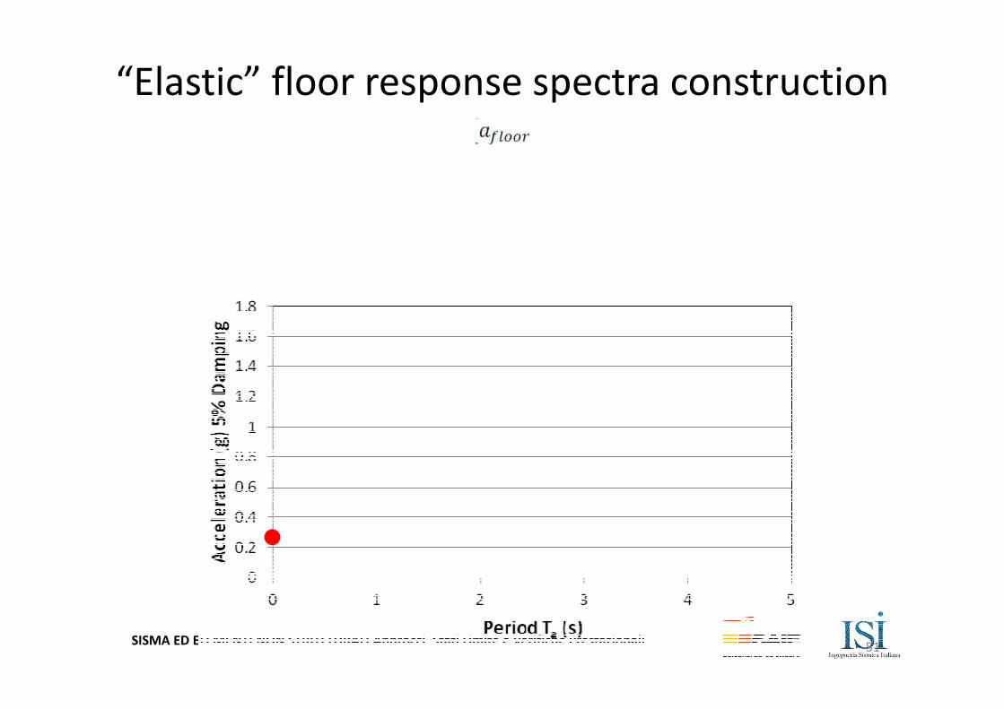
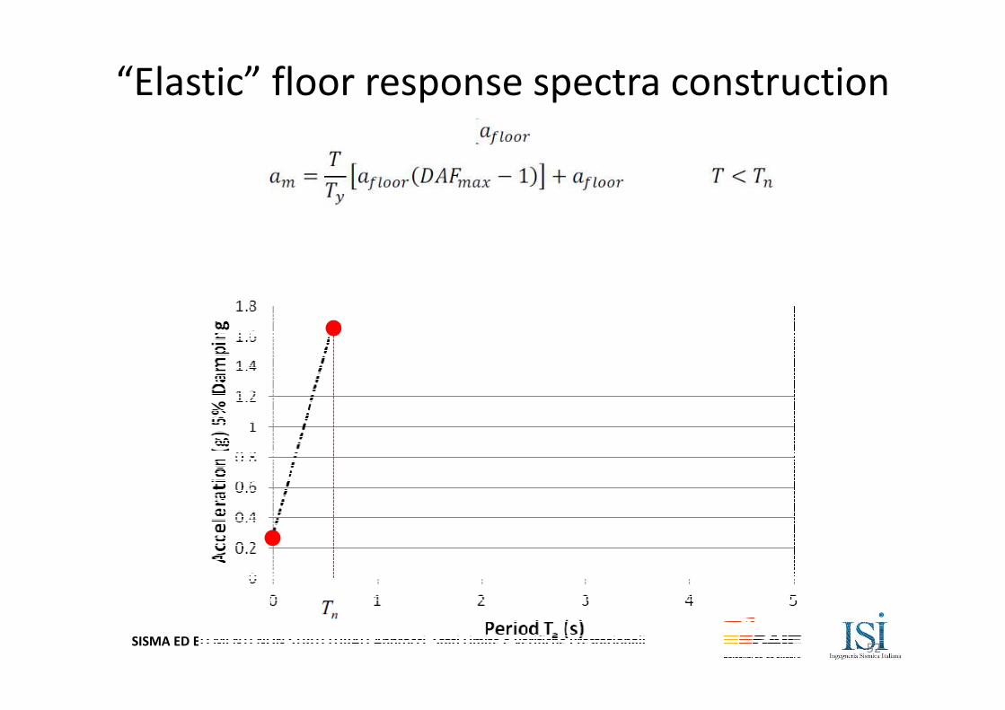
“Elastic” floor response spectra construction
51
SISMA ED ELEMENTI NON STRUTTURALI Approcci, Stati Limite e Verifiche Prestazionali
“Elastic” floor response spectra construction
52
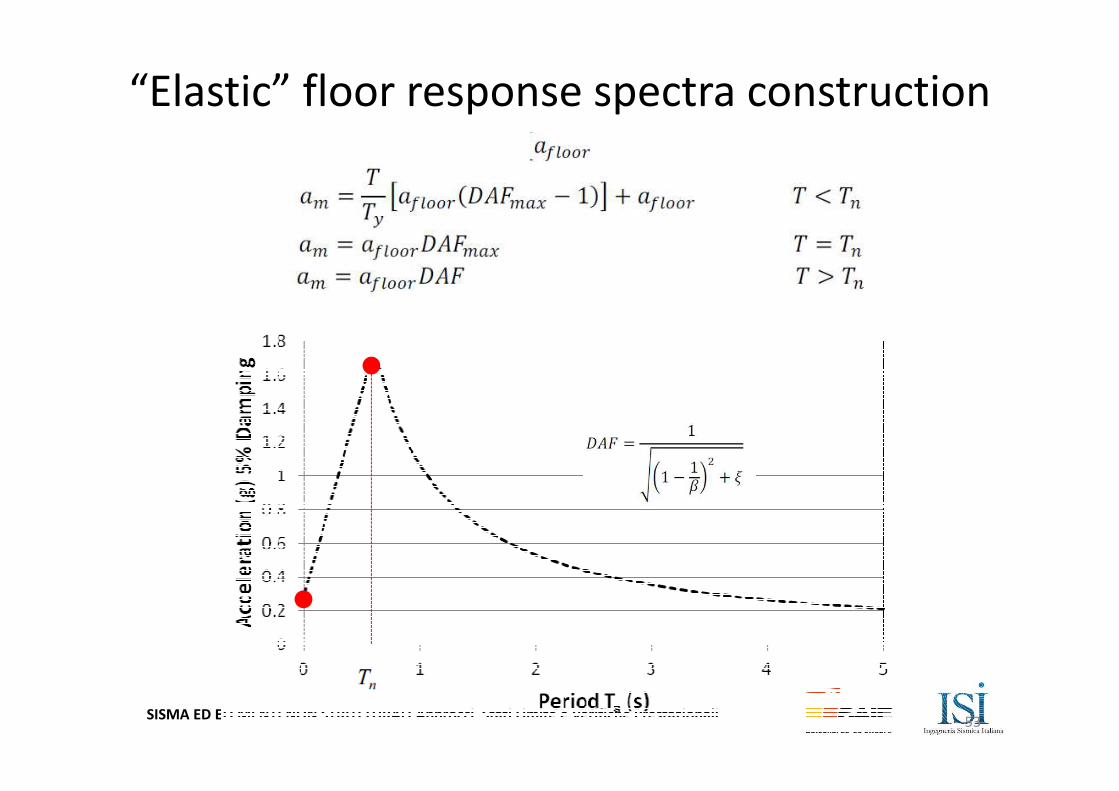
SISMA ED ELEMENTI NON STRUTTURALI Approcci, Stati Limite e Verifiche Prestazionali
“Elastic” floor response spectra construction
53
SISMA ED ELEMENTI NON STRUTTURALI Approcci, Stati Limite e Verifiche Prestazionali
What if the main structure
undergoes nonlinear behavior?
54
SISMA ED ELEMENTI NON STRUTTURALI Approcci, Stati Limite e Verifiche Prestazionali
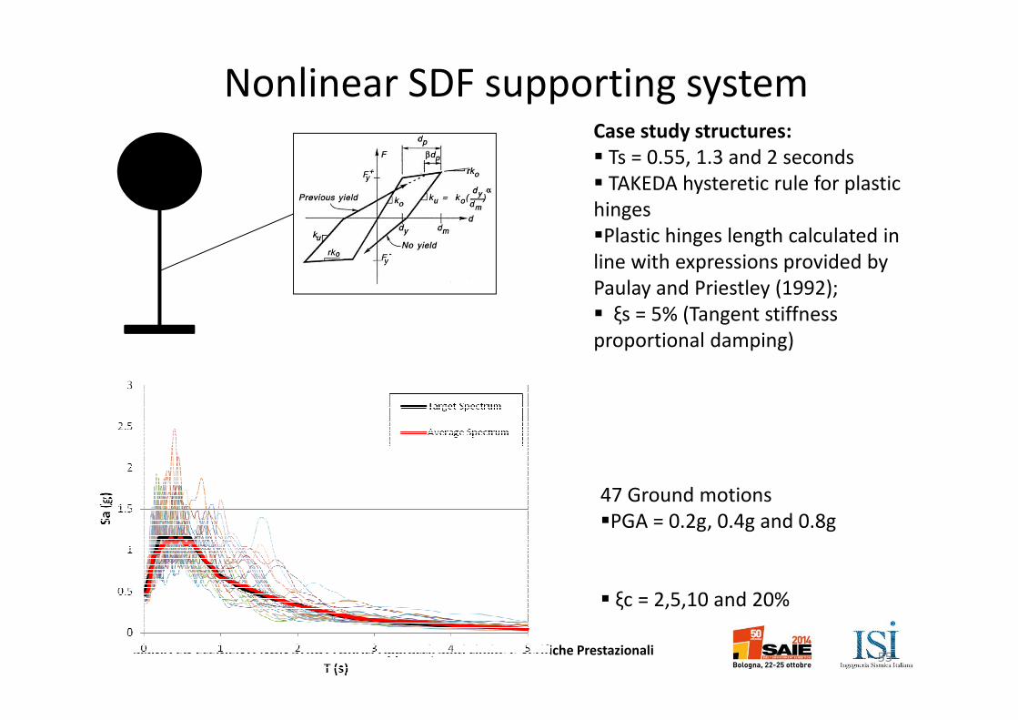
Nonlinear SDF supporting systemCase study structures:
� Ts = 0.55, 1.3 and 2 seconds
� TAKEDA hysteretic rule for plastic
hinges
�Plastic hinges length calculated in
line with expressions provided by
Paulay and Priestley (1992);
� ξs = 5% (Tangent stiffness
proportional damping)
47 Ground motions
�PGA = 0.2g, 0.4g and 0.8g
� ξc = 2,5,10 and 20%
55
SISMA ED ELEMENTI NON STRUTTURALI Approcci, Stati Limite e Verifiche Prestazionali
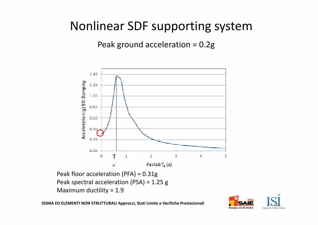
T
n
Peak ground acceleration = 0.2g
Peak floor acceleration (PFA) = 0.31g
Peak spectral acceleration (PSA) = 1.25 g
Maximum ductility = 1.9
Nonlinear SDF supporting system
56
SISMA ED ELEMENTI NON STRUTTURALI Approcci, Stati Limite e Verifiche Prestazionali
T
n
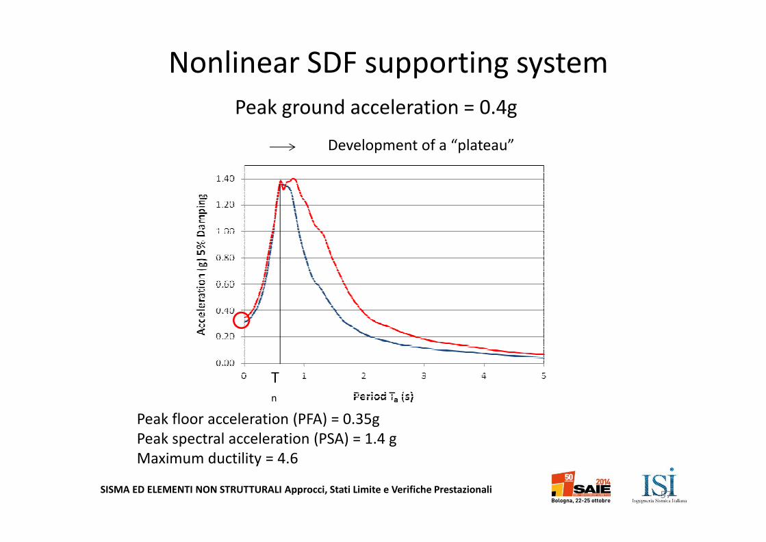
Peak floor acceleration (PFA) = 0.35g
Peak spectral acceleration (PSA) = 1.4 g
Maximum ductility = 4.6
Development of a “plateau”
Peak ground acceleration = 0.4g
Nonlinear SDF supporting system
57
SISMA ED ELEMENTI NON STRUTTURALI Approcci, Stati Limite e Verifiche Prestazionali
T
n
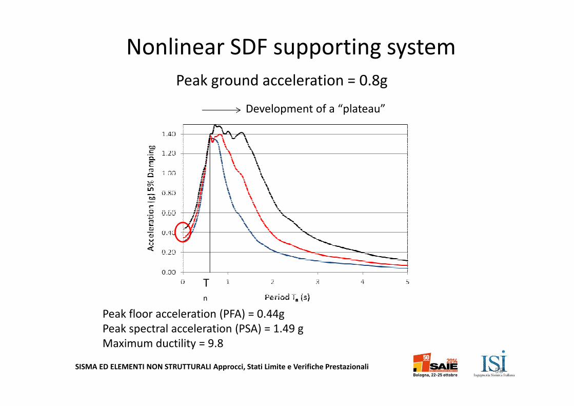
Peak floor acceleration (PFA) = 0.44g
Peak spectral acceleration (PSA) = 1.49 g
Maximum ductility = 9.8
Development of a “plateau”
Peak ground acceleration = 0.8g
Nonlinear SDF supporting system
58
SISMA ED ELEMENTI NON STRUTTURALI Approcci, Stati Limite e Verifiche Prestazionali
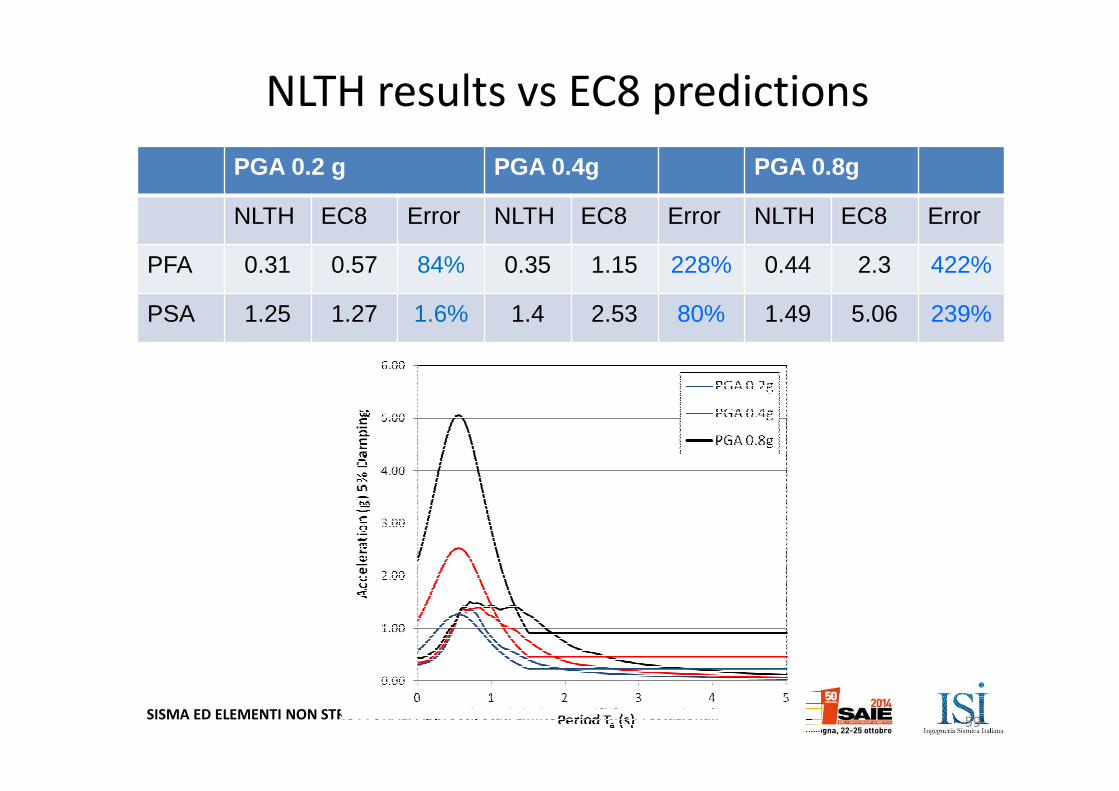
PGA 0.2 g PGA 0.4g PGA 0.8g
NLTH EC8 Error NLTH EC8 Error NLTH EC8 Error
PFA 0.31 0.57 84% 0.35 1.15 228% 0.44 2.3 422%
PSA 1.25 1.27 1.6% 1.4 2.53 80% 1.49 5.06 239%
NLTH results vs EC8 predictions
59
SISMA ED ELEMENTI NON STRUTTURALI Approcci, Stati Limite e Verifiche Prestazionali
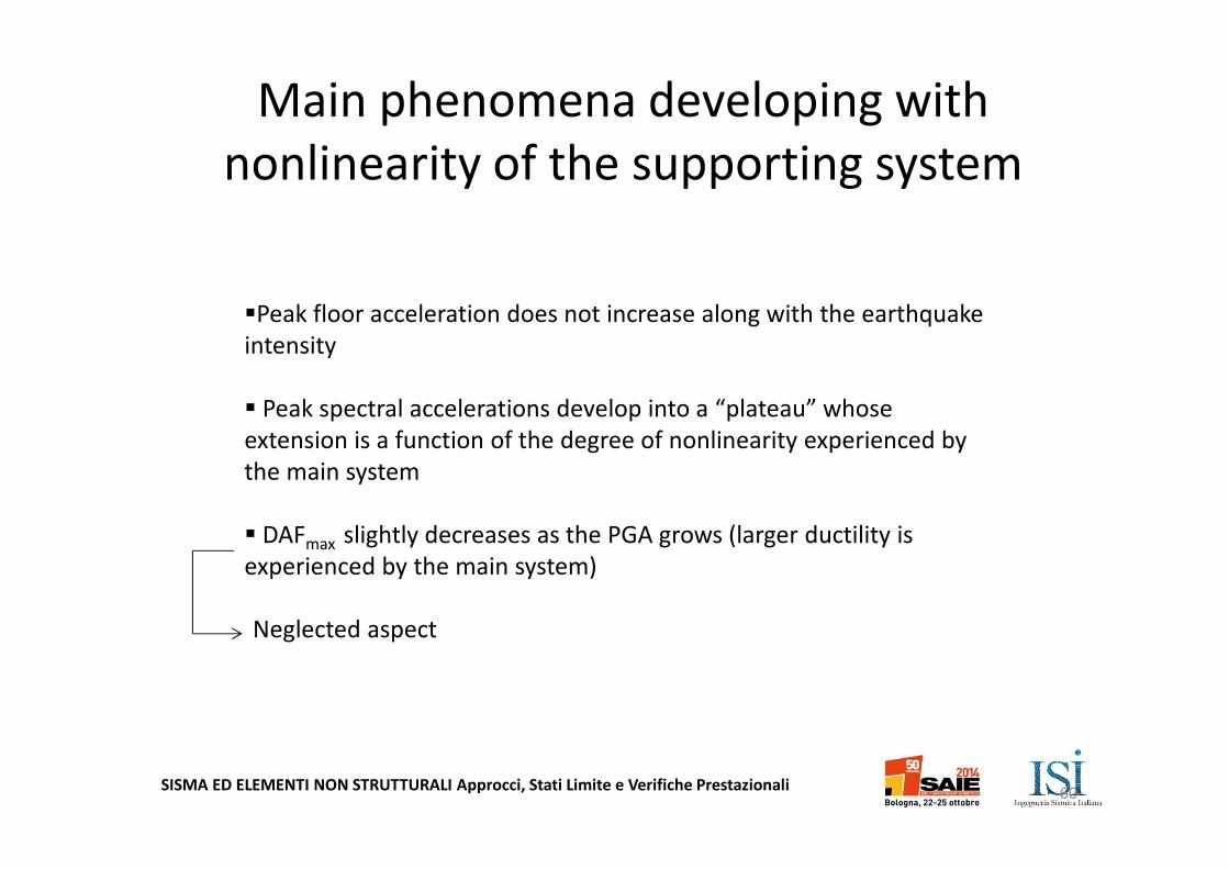
Main phenomena developing with
nonlinearity of the supporting system
�Peak floor acceleration does not increase along with the earthquake
intensity
� Peak spectral accelerations develop into a “plateau” whose
extension is a function of the degree of nonlinearity experienced by
the main system
� DAFmax slightly decreases as the PGA grows (larger ductility is
experienced by the main system)
Neglected aspect
60
SISMA ED ELEMENTI NON STRUTTURALI Approcci, Stati Limite e Verifiche Prestazionali
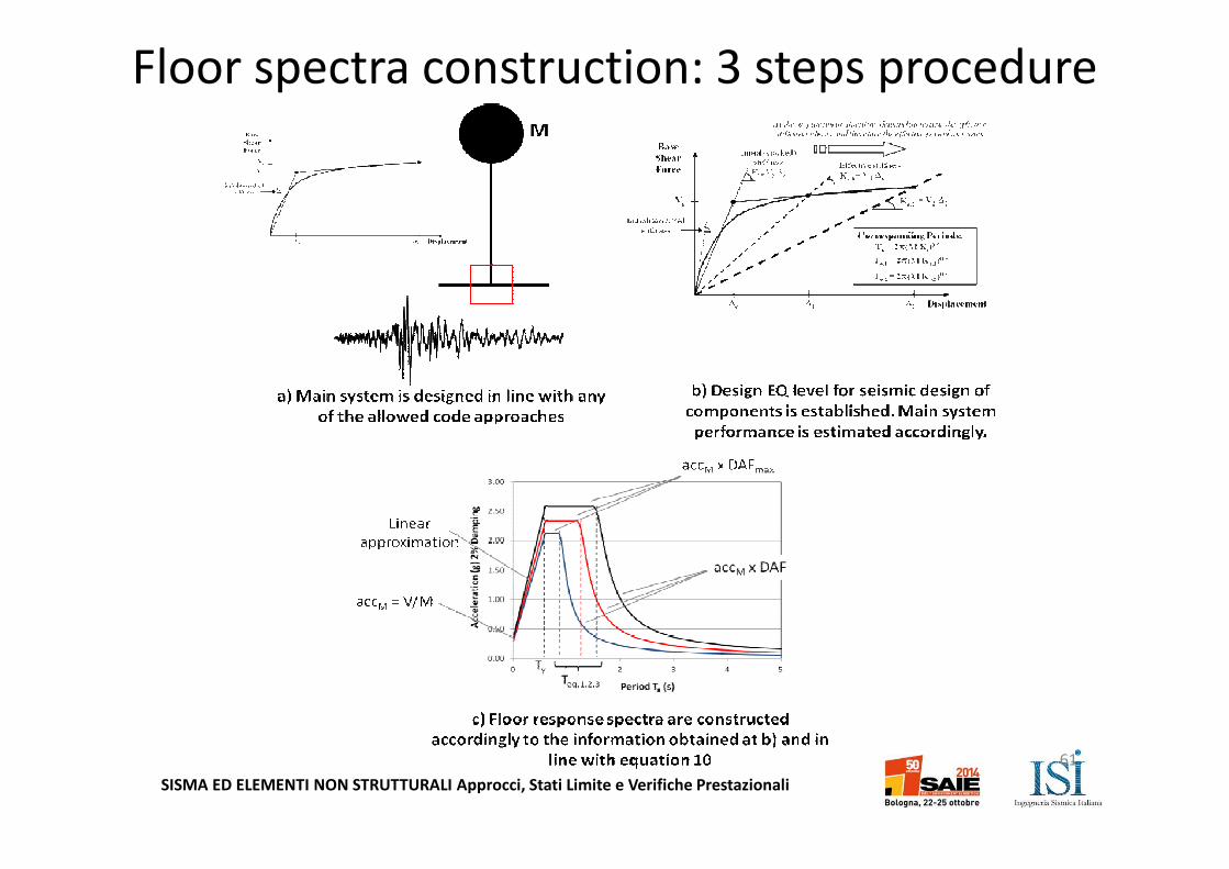
Floor spectra construction: 3 steps procedure
61
SISMA ED ELEMENTI NON STRUTTURALI Approcci, Stati Limite e Verifiche Prestazionali
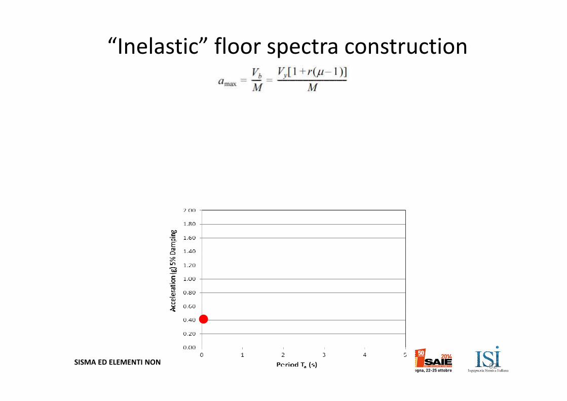
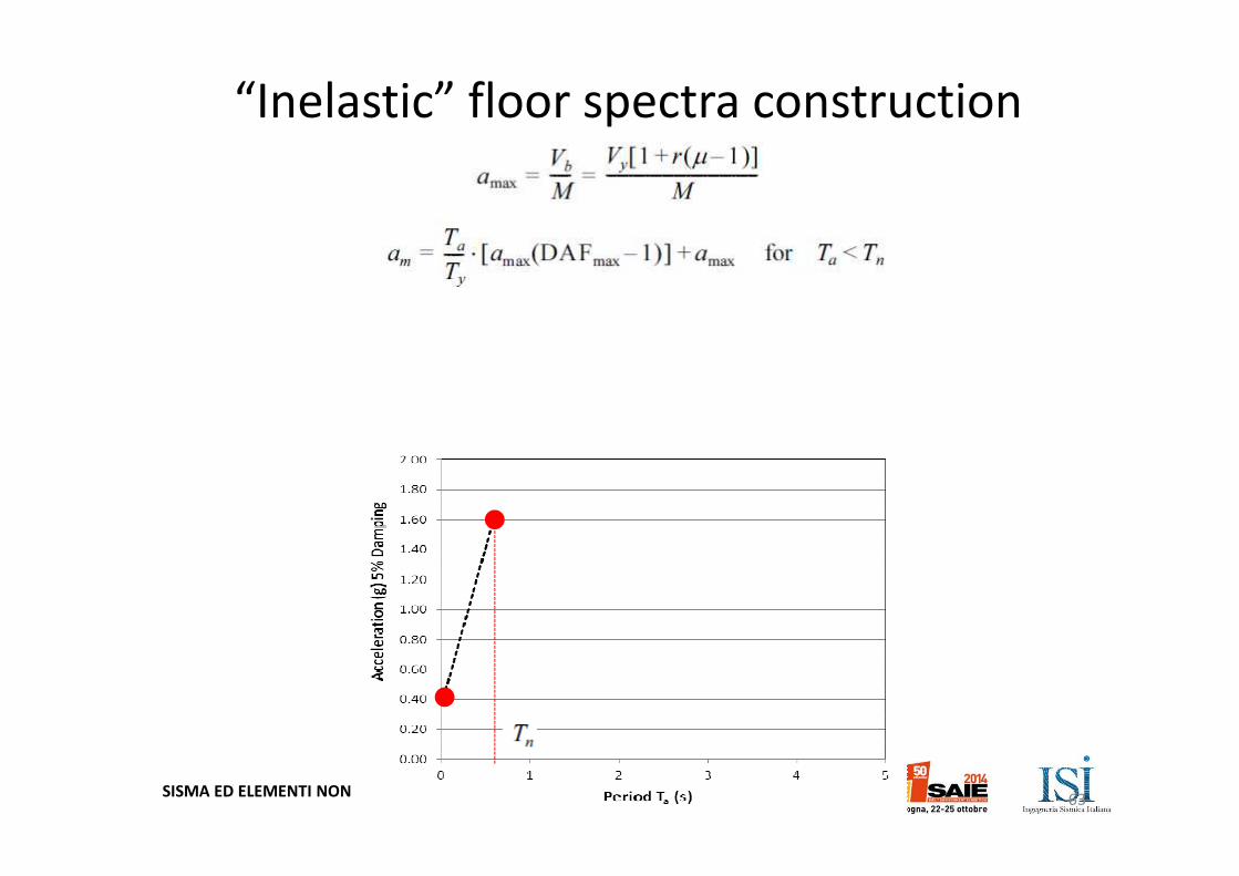
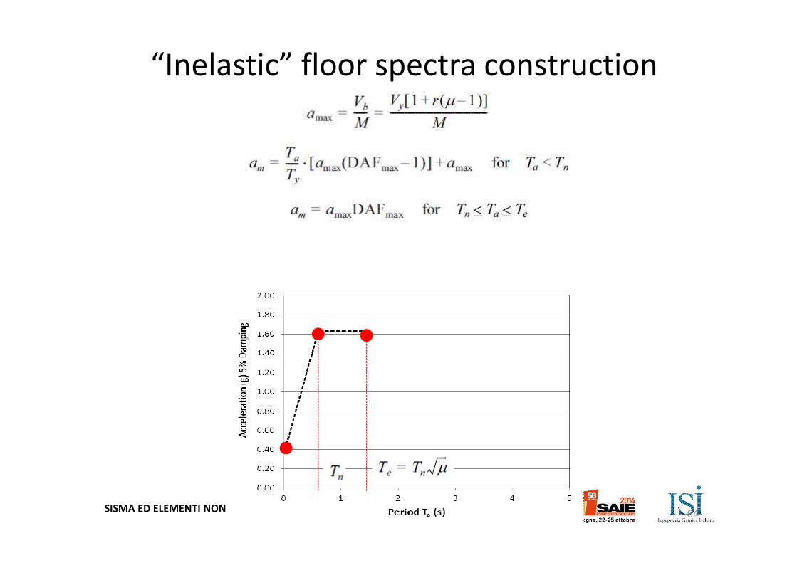
“Inelastic” floor spectra construction
62
SISMA ED ELEMENTI NON STRUTTURALI Approcci, Stati Limite e Verifiche Prestazionali
“Inelastic” floor spectra construction
63
SISMA ED ELEMENTI NON STRUTTURALI Approcci, Stati Limite e Verifiche Prestazionali
“Inelastic” floor spectra construction
64
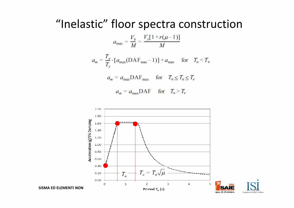
SISMA ED ELEMENTI NON STRUTTURALI Approcci, Stati Limite e Verifiche Prestazionali
“Inelastic” floor spectra construction
65
SISMA ED ELEMENTI NON STRUTTURALI Approcci, Stati Limite e Verifiche Prestazionali
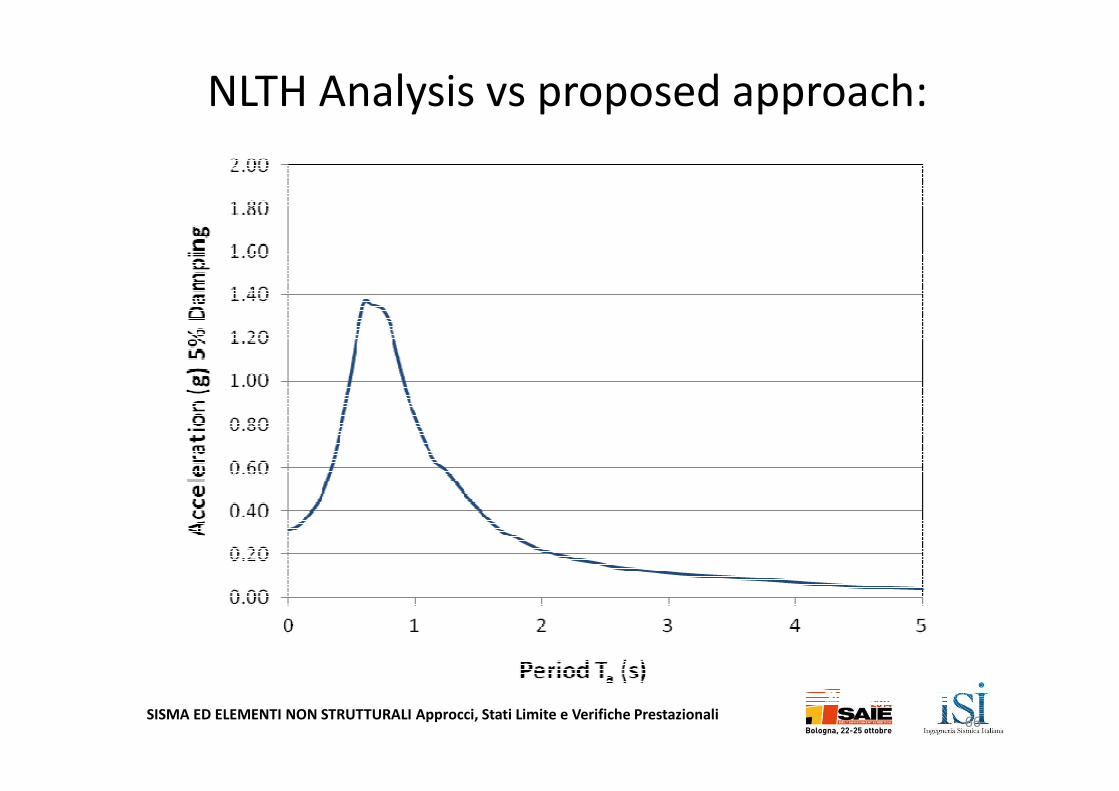
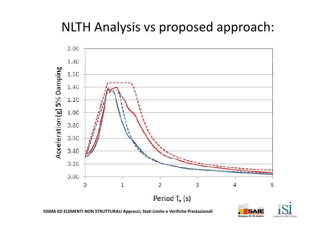
NLTH Analysis vs proposed approach:
66
SISMA ED ELEMENTI NON STRUTTURALI Approcci, Stati Limite e Verifiche Prestazionali
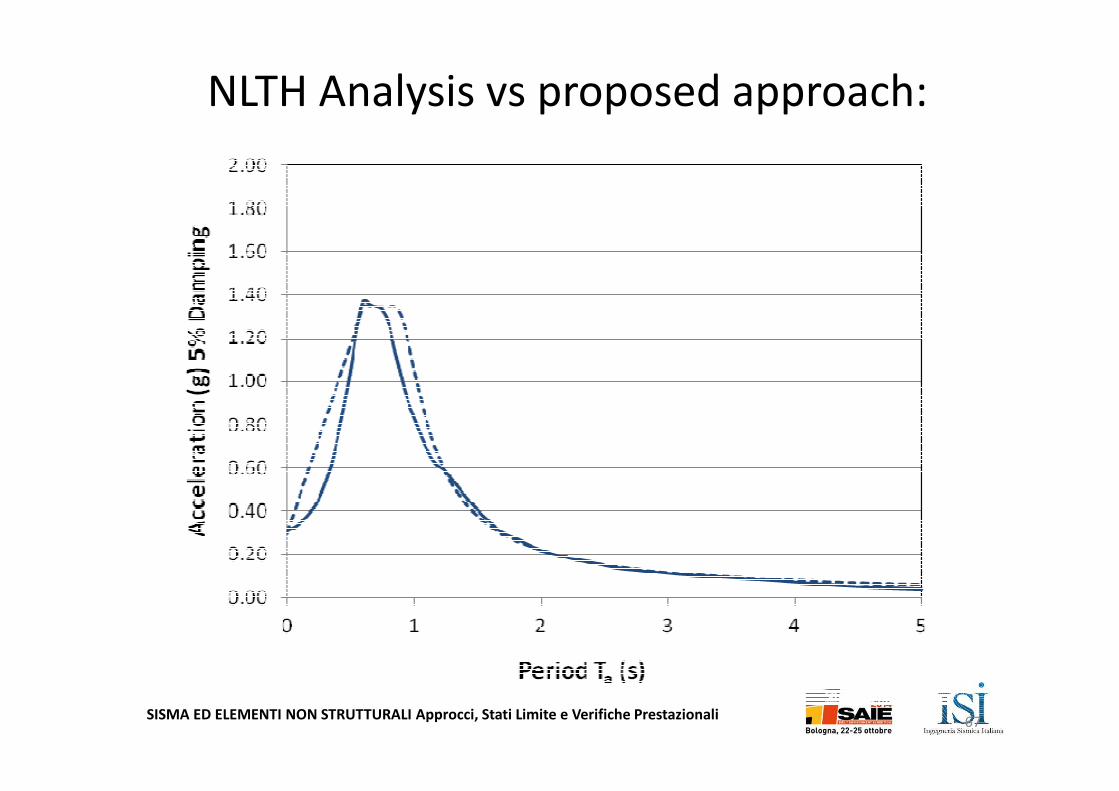
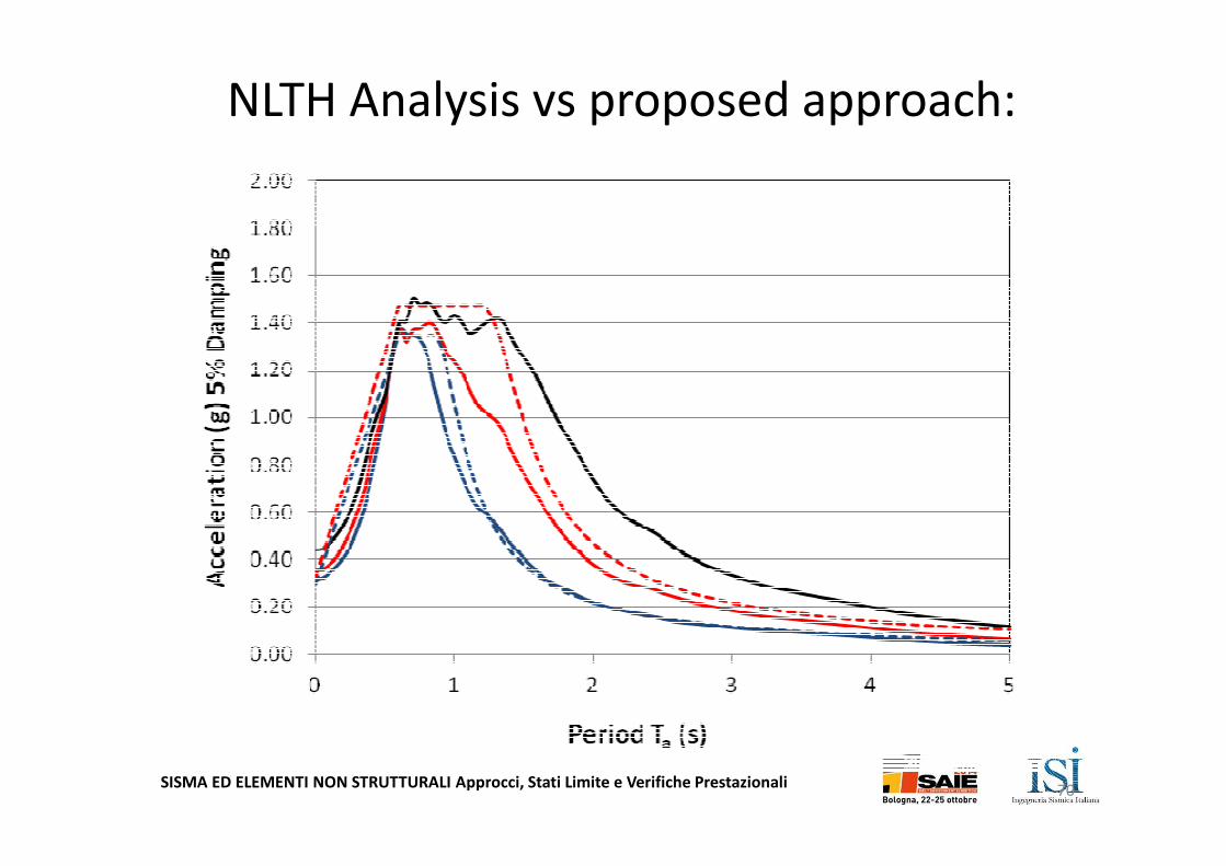
NLTH Analysis vs proposed approach:
67
SISMA ED ELEMENTI NON STRUTTURALI Approcci, Stati Limite e Verifiche Prestazionali
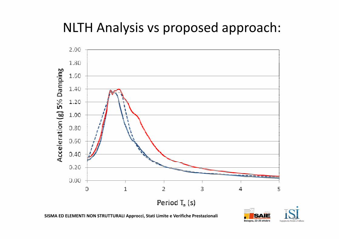
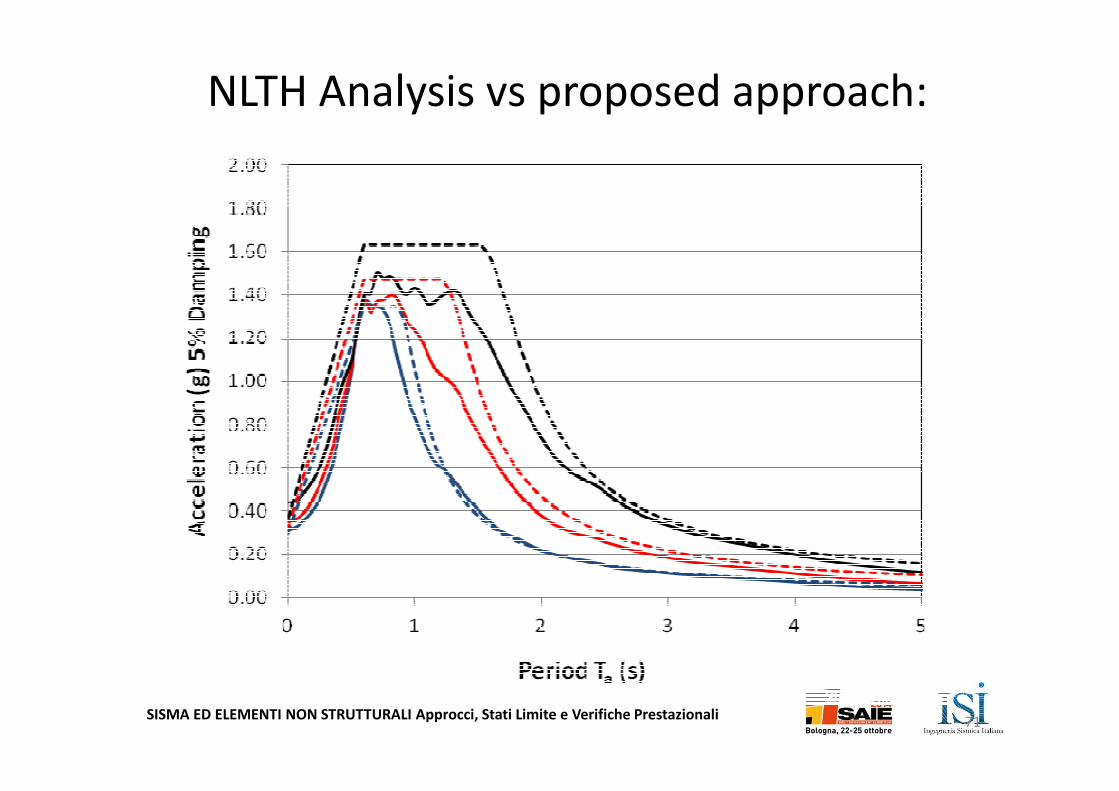
NLTH Analysis vs proposed approach:
68
SISMA ED ELEMENTI NON STRUTTURALI Approcci, Stati Limite e Verifiche Prestazionali
NLTH Analysis vs proposed approach:
69
SISMA ED ELEMENTI NON STRUTTURALI Approcci, Stati Limite e Verifiche Prestazionali
NLTH Analysis vs proposed approach:
70
SISMA ED ELEMENTI NON STRUTTURALI Approcci, Stati Limite e Verifiche Prestazionali
NLTH Analysis vs proposed approach:
71
SISMA ED ELEMENTI NON STRUTTURALI Approcci, Stati Limite e Verifiche Prestazionali72
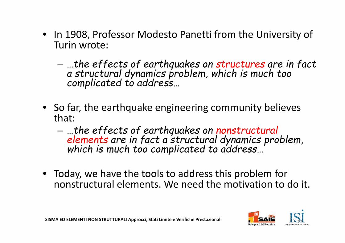
• In 1908, Professor Modesto Panetti from the University of Turin wrote:
– …the effects of earthquakes on structures are in fact a structural dynamics problem, which is much too complicated to address…
• So far, the earthquake engineering community believes that:– …the effects of earthquakes on nonstructural
elements are in fact a structural dynamics problem, which is much too complicated to address…
• Today, we have the tools to address this problem for nonstructural elements. We need the motivation to do it.