POMPE AD INGRANAGGI GEAR PUMPS - antech-hyd.co.uk · La precisione e la cura nella costruzione dei...
24
POMPE AD INGRANAGGI GEAR PUMPS
-
Upload
phamkhuong -
Category
Documents
-
view
216 -
download
0
Transcript of POMPE AD INGRANAGGI GEAR PUMPS - antech-hyd.co.uk · La precisione e la cura nella costruzione dei...
POMPE AD INGRANAGGI
GEAR PUMPS
CTVL00IECTBGrev6IE

CATALOGO TECNICO
TECHNICALCATALOGUE
P. 4 POMPE AD INGRANAGGI GEAR PUMPS
Il presente catalogo include pompe ad ingranaggi esterni del Gr. 1, Gr. 2 e del Gr. 3 sia in configu-razione singola che in tandem (pompa multipla). Sono dotate di flange e coperchi in alluminio o in ghisa. Il bilanciamento idrostatico dei rasamenti (boccole) è del tipo doppia compensazione con ripresa del gioco assiale mediante apposita area predefinita. Lubrificazione interna e compensazione sono proporzionali alla pressione di esercizio.La precisione e la cura nella costruzione dei parti-colari consentono l’intercambiabilità delle flange di fissaggio e degli ingranaggi (nell’ambito della stessa cilindrata) permettendo in tal modo maggior flessibilità e minori impegni di magazzino presso il cliente. Sono disponibili le varie esecuzioni secondo gli standard più diffusi (europeo, tedesco, SAE) e, su richiesta, esiste la possibilità di personalizzazioni del cliente. Tutte le pompe sono predisposte per il traino di una eventuale pompa posteriore me-diante un apposito kit di trasformazione fornibile separatamente.
Condizioni e limiti di funzionamentoFluido consigliato: olio idraulico a base minerale con elevato indice di viscosità (tenendo conto delle condizioni di funzionamento dell’impianto).
Temperatura consigliata: 20 60 °C.
Temperatura limite con guarnizioni in NBR:-15 80 °C
Temperatura limite con guarnizioni in FPM (Viton): -10 110 °C.
Pressione ammessa in aspirazione: 0.7 3 bar assoluti (10 44 psi).
Viscosità raccomandata: 15 92 c.St.
Viscosità limite all’avviamento: 2500 c.St.
Filtraggio per pressioni di esercizio fino a 150 bar (fino a 2175 psi): 26/23 ISO DIS 4406.
Filtraggio per pressioni di esercizio >150 bar (>2175 psi): 23/20 ISO DIS 4406.
The present range includes external gear pumps, Group 1, Group 2 and Group 3, single and tandem construction (multiple pump), with aluminium or cast iron end cap and mounting flange. Floating bushing, double compensated pressure-balanced design with special area for resetting of the end float clearance. Internal lubrication and pressure compensation are performed proportionally to the operating pressure of the system. Precision machining and top accuracy of all construction details make use of fixation flanges perfectly interchangeable for models of the same delivery range providing more flexibility and less customers’ stocks. The various construction types are available in compliant versions to the applicable Standards (European, German and SAE). On request, clients may ask for customized versions too.All pumps are designed for combined operation with an eventual retrofittable rear pump. Assembly kit for rear-mount is available on request.
Operating conditionsRecommended fluid: High-viscosity, mineral hydraulic oil (please always pay attention to the operating conditions of the equipment).
Recommended temperature range: 20 60 °C
Operating temperature range for NBR gaskets: -15 80 °C.
Operating temperature range for FPM (Viton) gaskets:-10 110 °C.
Admissible suction pressure: 0.7 3 bar absolute (10 44 psi absolute).
Recommended viscosity range: 15 92 c.St.
Max viscosity at start-up: 2500 c.St.
Filtering for operating pressure up to 150 bar (up to 2175 psi): 26/23 ISO DIS 4406.
Filtering for operating pressure >150 bar (>2175 psi): 23/20 ISO DIS 4406.
CARATTERISTICHE GENERALIMAIN FEATURES
POMPE AD INGRANAGGI GEAR PUMPS P. 5
Note per l’installazione- Verificare il corretto senso di rotazione della
pompa.- Collegare il condotto di aspirazione al lato della
pompa riportante l’apposito riferimento o, in sua assenza, al foro di dimensione maggiore.
- Non sono ammessi carichi assiali e/o radiali sull’albero della pompa: effettuare il collegamento all’albero motore con giunto non rigido, appo-sitamente lubrificato e libero di muoversi assial-mente.
- In caso di presenza di carichi sull’albero della pompa, interporre un supporto munito di cusci-netti.
- In caso di verniciatura della pompa proteggere l’anello di tenuta per albero rotante.
- Rimuovere eventuali impurità quali polvere o particelle abrasive dalla zona dell’albero rotante a contatto con l’anello di tenuta.
- Rimuovere trucioli e/o impurità dai fori di con-nessione e dai piani di appoggio su corpo e flangia di fissaggio.
- Riempire la pompa di fluido facendola ruotare a mano per evitare il primo avviamento a secco
- Agevolare la fuoriuscita dell’aria dall’impianto alla prima accensione allentando momentanea-mente il tubo di mandata della pompa.
- Mantenere l’olio pulito a salvaguardia di tutti i componenti dell’impianto, controllando periodi-camente lo stato dei filtri.
- Eseguire eventuali rabbocchi con olio idraulico dello stesso tipo.
Important installation tips- Check for correct pump rotation in the proper
direction.- Connect the suction pipe to the pump side
marked by the relevant sign or, failure of any mark, to the largest hole.
- Do not apply any axial/radial loads on the shaft of the pump. Do not use a rigid coupling for connection to the motor shaft, provide for due lubrication and axial clearance of the coupling.
- If a load is to be applied on the shaft of the pump, be sure to install a suitable external bearing for the load.
- Protect the seal of the drive shaft before painting the pump.
- Accurately remove eventual foreign matters (such as dust and abrasive particles) from the shaft area touching the sealing ring.
- Remove chips and/or metal shavings from the connection holes, from the body bearing faces and from the mounting flange.
- As you fill fluid into the pump, be sure to manually let the pump rotate in order to avoid dry start-ups.
- Release the delivery pipe to facilitate bleeding the pump at first startup.
- Be sure to keep running the pump with very clean oil to avoid even major damages to the various parts and components. Perform regular periodic controls of the filters.
- If required, perform oil touch-ups using oil of the same kind.
I dati contenuti nel presente catalogo sono in-dicativi e possono essere modificati senza alcun preavviso.
The information provided in this catalogue is subject to change without notice.
©2017 B&C

P. 10 POMPE A INGRANAGGI GEAR PUMPS
DATI TECNICI TECHNICAL DATA
POMPE AD INGRANAGGI GEAR PUMPS P. 11
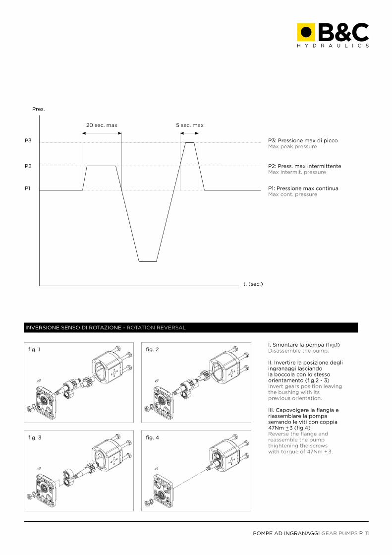
Pres.
t. (sec.)
fig. 1
fig. 3
fig. 2
fig. 4
P3
P2 P2: Press. max intermittenteMax intermit. pressure
P1 P1: Pressione max continuaMax cont. pressure
20 sec. max 5 sec. max
P3: Pressione max di piccoMax peak pressure
I. Smontare la pompa (fig.1)Disassemble the pump.
II. Invertire la posizione degliingranaggi lasciandola boccola con lo stessoorientamento (fig.2 - 3)Invert gears position leavingthe bushing with itsprevious orientation.
III. Capovolgere la flangia eriassemblare la pompaserrando le viti con coppia47Nm +_3 (fig.4)Reverse the flange andreassemble the pump thightening the screws with torque of 47Nm +_3.
INVERSIONE SENSO DI ROTAZIONE - ROTATION REVERSAL
GRUPPO 1 GROUP 1
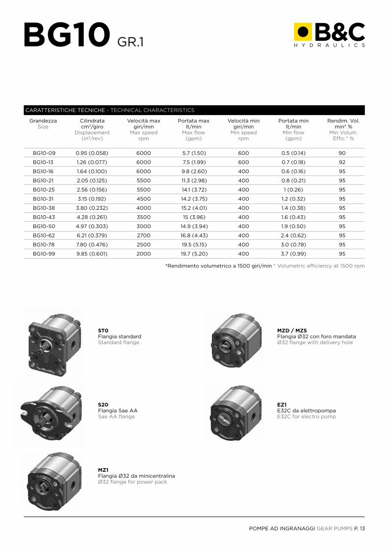
POMPE AD INGRANAGGI GEAR PUMPS P. 13
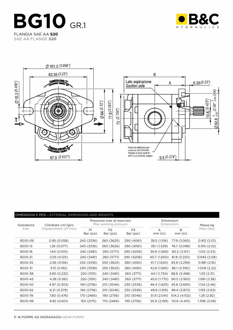
GrandezzaSize
*Rendimento volumetrico a 1500 giri/min * Volumetric efficiency at 1500 rpm
ST0Flangia standardStandard flange
MZD / MZSFlangia Ø32 con foro mandataØ32 flange with delivery hole
S20Flangia Sae AASae AA flange
EZ1E32C da elettropompaE32C for electro pump
MZ1Flangia Ø32 da minicentralinaØ32 flange for power pack
Cilindratacm3/giro
Displacement (in3/rev)
Velocità maxgiri/min
Max speedrpm
Velocità mingiri/min
Min speedrpm
Portata maxlt/min
Max flow(gpm)
Portata minlt/min
Min flow(gpm)
Rendim. Vol. min* %
Min Volum. Effic.* %
BG10-09
BG10-13
BG10-16
BG10-21
BG10-25
BG10-31
BG10-38
BG10-43
BG10-50
BG10-62
BG10-78
BG10-99
0.95 (0.058)
1.26 (0.077)
1.64 (0.100)
2.05 (0.125)
2.56 (0.156)
3.15 (0.192)
3.80 (0.232)
4.28 (0.261)
4.97 (0.303)
6.21 (0.379)
7.80 (0.476)
9.85 (0.601)
6000
6000
6000
5500
5500
4500
4000
3500
3000
2700
2500
2000
5.7 (1.50)
7.5 (1.99)
9.8 (2.60)
11.3 (2.98)
14.1 (3.72)
14.2 (3.75)
15.2 (4.01)
15 (3.96)
14.9 (3.94)
16.8 (4.43)
19.5 (5.15)
19.7 (5.20)
600
600
400
400
400
400
400
400
400
400
400
400
0.5 (0.14)
0.7 (0.18)
0.6 (0.16)
0.8 (0.21)
1 (0.26)
1.2 (0.32)
1.4 (0.38)
1.6 (0.43)
1.9 (0.50)
2.4 (0.62)
3.0 (0.78)
3.7 (0.99)
90
92
95
95
95
95
95
95
95
95
95
95
CARATTERISTICHE TECNICHE - TECHNICAL CHARACTERISTICS
BG10 GR.1
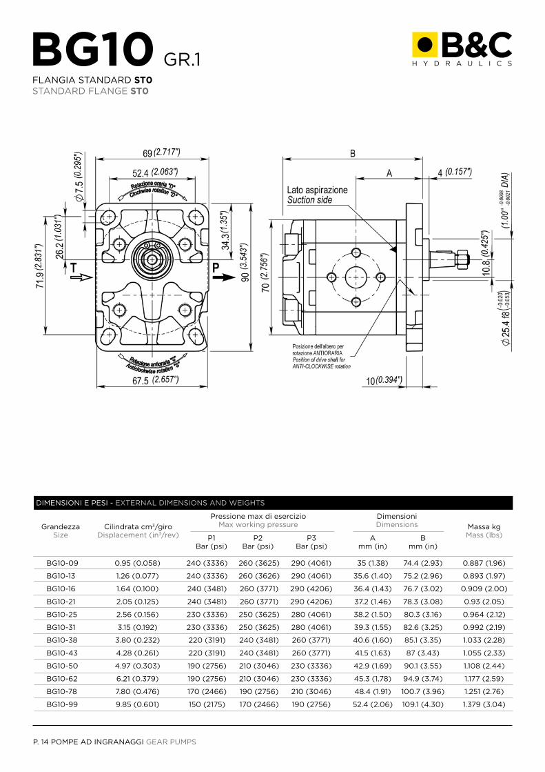
P. 14 POMPE AD INGRANAGGI GEAR PUMPS
BG10 GR.1FLANGIA STANDARD ST0STANDARD FLANGE ST0
GrandezzaSize
Massa kgMass (lbs)
Cilindrata cm3/giroDisplacement (in3/rev)
DimensioniDimensions
BG10-09
BG10-13
BG10-16
BG10-21
BG10-25
BG10-31
BG10-38
BG10-43
BG10-50
BG10-62
BG10-78
BG10-99
0.95 (0.058)
1.26 (0.077)
1.64 (0.100)
2.05 (0.125)
2.56 (0.156)
3.15 (0.192)
3.80 (0.232)
4.28 (0.261)
4.97 (0.303)
6.21 (0.379)
7.80 (0.476)
9.85 (0.601)
240 (3336)
240 (3336)
240 (3481)
240 (3481)
230 (3336)
230 (3336)
220 (3191)
220 (3191)
190 (2756)
190 (2756)
170 (2466)
150 (2175)
260 (3625)
260 (3626)
260 (3771)
260 (3771)
250 (3625)
250 (3625)
240 (3481)
240 (3481)
210 (3046)
210 (3046)
190 (2756)
170 (2466)
290 (4061)
290 (4061)
290 (4206)
290 (4206)
280 (4061)
280 (4061)
260 (3771)
260 (3771)
230 (3336)
230 (3336)
210 (3046)
190 (2756)
35 (1.38)
35.6 (1.40)
36.4 (1.43)
37.2 (1.46)
38.2 (1.50)
39.3 (1.55)
40.6 (1.60)
41.5 (1.63)
42.9 (1.69)
45.3 (1.78)
48.4 (1.91)
52.4 (2.06)
74.4 (2.93)
75.2 (2.96)
76.7 (3.02)
78.3 (3.08)
80.3 (3.16)
82.6 (3.25)
85.1 (3.35)
87 (3.43)
90.1 (3.55)
94.9 (3.74)
100.7 (3.96)
109.1 (4.30)
0.887 (1.96)
0.893 (1.97)
0.909 (2.00)
0.93 (2.05)
0.964 (2.12)
0.992 (2.19)
1.033 (2.28)
1.055 (2.33)
1.108 (2.44)
1.177 (2.59)
1.251 (2.76)
1.379 (3.04)
Amm (in)
Pressione max di esercizioMax working pressure
P1Bar (psi)
P2Bar (psi)
P3Bar (psi)
Bmm (in)
DIMENSIONI E PESI - EXTERNAL DIMENSIONS AND WEIGHTS
POMPE AD INGRANAGGI GEAR PUMPS P. 15
0 Standard Standard
DS
A
ST0
Rotazione destra Clockwise rotation Rotazione sinistra Anticlockwise rotation
Alluminio Aluminium
Standard Standard
0V
Tenute in Nbr Nbr seals Tenute in Viton® Viton® seals
0.9509
EEx
2.5625
4.9750
1.6416
GG4
3.8038
7.8078
1.2613
TT4
3.1531
6.2162
2.0521
UUx
4.2843
9.8599
T80
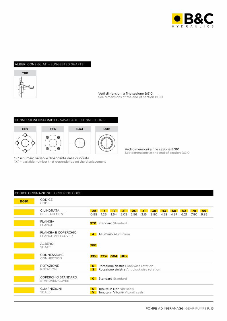
COPERCHIO STANDARDSTANDARD COVER
CONNESSIONECONNECTION
CILINDRATADISPLACEMENT
CODICECODE
ALBEROSHAFT
ROTAZIONEROTATION
FLANGIA E COPERCHIOFLANGE AND COVER
FLANGIAFLANGE
GUARNIZIONISEALS
BG10
CODICE ORDINAZIONE - ORDERING CODE
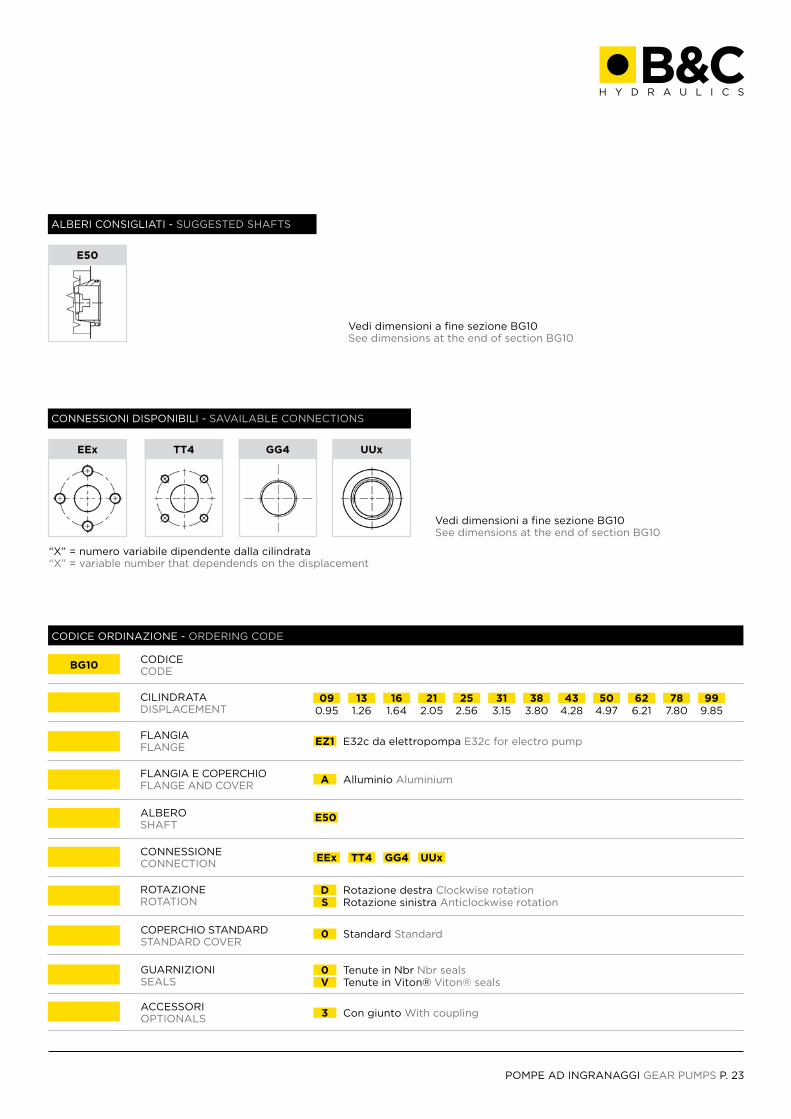
ALBERI CONSIGLIATI - SUGGESTED SHAFTS
CONNESSIONI DISPONIBILI - SAVAILABLE CONNECTIONS
Vedi dimensioni a fine sezione BG10See dimensions at the end of section BG10
Vedi dimensioni a fine sezione BG10See dimensions at the end of section BG10
“X” = numero variabile dipendente dalla cilindrata“X” = variable number that dependends on the displacement
T80
EEx TT4 GG4 UUx
P. 16 POMPE AD INGRANAGGI GEAR PUMPS
BG10-09
BG10-13
BG10-16
BG10-21
BG10-25
BG10-31
BG10-38
BG10-43
BG10-50
BG10-62
BG10-78
BG10-99
BG10 GR.1FLANGIA SAE AA S20SAE AA FLANGE S20
GrandezzaSize
Massa kgMass (lbs)
Cilindrata cm3/giroDisplacement (in3/rev)
DimensioniDimensions
0.95 (0.058)
1.26 (0.077)
1.64 (0.100)
2.05 (0.125)
2.56 (0.156)
3.15 (0.192)
3.80 (0.232)
4.28 (0.261)
4.97 (0.303)
6.21 (0.379)
7.80 (0.476)
9.85 (0.601)
240 (3336)
240 (3336)
240 (3481)
240 (3481)
230 (3336)
230 (3336)
220 (3191)
220 (3191)
190 (2756)
190 (2756)
170 (2466)
150 (2175)
260 (3625)
260 (3626)
260 (3771)
260 (3771)
250 (3625)
250 (3625)
240 (3481)
240 (3481)
210 (3046)
210 (3046)
190 (2756)
170 (2466)
290 (4061)
290 (4061)
290 (4206)
290 (4206)
280 (4061)
280 (4061)
260 (3771)
260 (3771)
230 (3336)
230 (3336)
210 (3046)
190 (2756)
38.5 (1.516)
39.1 (1.539)
39.9 (1.569)
40.7 (1.600)
41.7 (1.640)
42.8 (1.685)
44.1 (1.734)
45.0 (1.772)
46.4 (1.825)
48.8 (1.919)
51.9 (2.041)
55.9 (2.199)
77.9 (3.065)
78.7 (3.098)
80.2 (3.157)
81.8 (3.220)
83.8 (3.299)
86.1 (3.390)
88.6 (3.488)
90.5 (3.563)
93.6 (3.683)
98.4 (3.872)
104.2 (4.102)
112.6 (4.431)
0.912 (2.01)
0.915 (2.02)
1.012 (2.23)
0.945 (2.08)
0.981 (2.16)
1.008 (2.22)
1.05 (2.31)
1.081 (2.38)
1.124 (2.48)
1.193 (2.63)
1.28 (2.82)
1.396 (3.08)
Amm (in)
Pressione max di esercizioMax working pressure
P1Bar (psi)
P2Bar (psi)
P3Bar (psi)
Bmm (in)
DIMENSIONI E PESI - EXTERNAL DIMENSIONS AND WEIGHTS

POMPE AD INGRANAGGI GEAR PUMPS P. 17
0 Standard Standard
DS
A
S20
Rotazione destra Clockwise rotation Rotazione sinistra Anticlockwise rotation
Alluminio Aluminium
Flangia Sae AA Sae AA Flange
0V
Tenute in Nbr Nbr seals Tenute in Viton® Viton® seals
0.9509
EEx
2.5625
4.9750
1.6416
GG4
3.8038
7.8078
1.2613
TT4
3.1531
6.2162
2.0521
UUx
4.2843
9.8599
P30 S90
COPERCHIO STANDARDSTANDARD COVER
CONNESSIONECONNECTION
CILINDRATADISPLACEMENT
CODICECODE
ALBEROSHAFT
ROTAZIONEROTATION
FLANGIA E COPERCHIOFLANGE AND COVER
FLANGIAFLANGE
GUARNIZIONISEALS
BG10
CODICE ORDINAZIONE - ORDERING CODE
ALBERI CONSIGLIATI - SUGGESTED SHAFTS
CONNESSIONI DISPONIBILI - SAVAILABLE CONNECTIONS
“X” = numero variabile dipendente dalla cilindrata“X” = variable number that dependends on the displacement
P30 S90
EEx TT4 GG4 UUx
Vedi dimensioni a fine sezione BG10See dimensions at the end of section BG10
Vedi dimensioni a fine sezione BG10See dimensions at the end of section BG10
P. 18 POMPE AD INGRANAGGI GEAR PUMPS
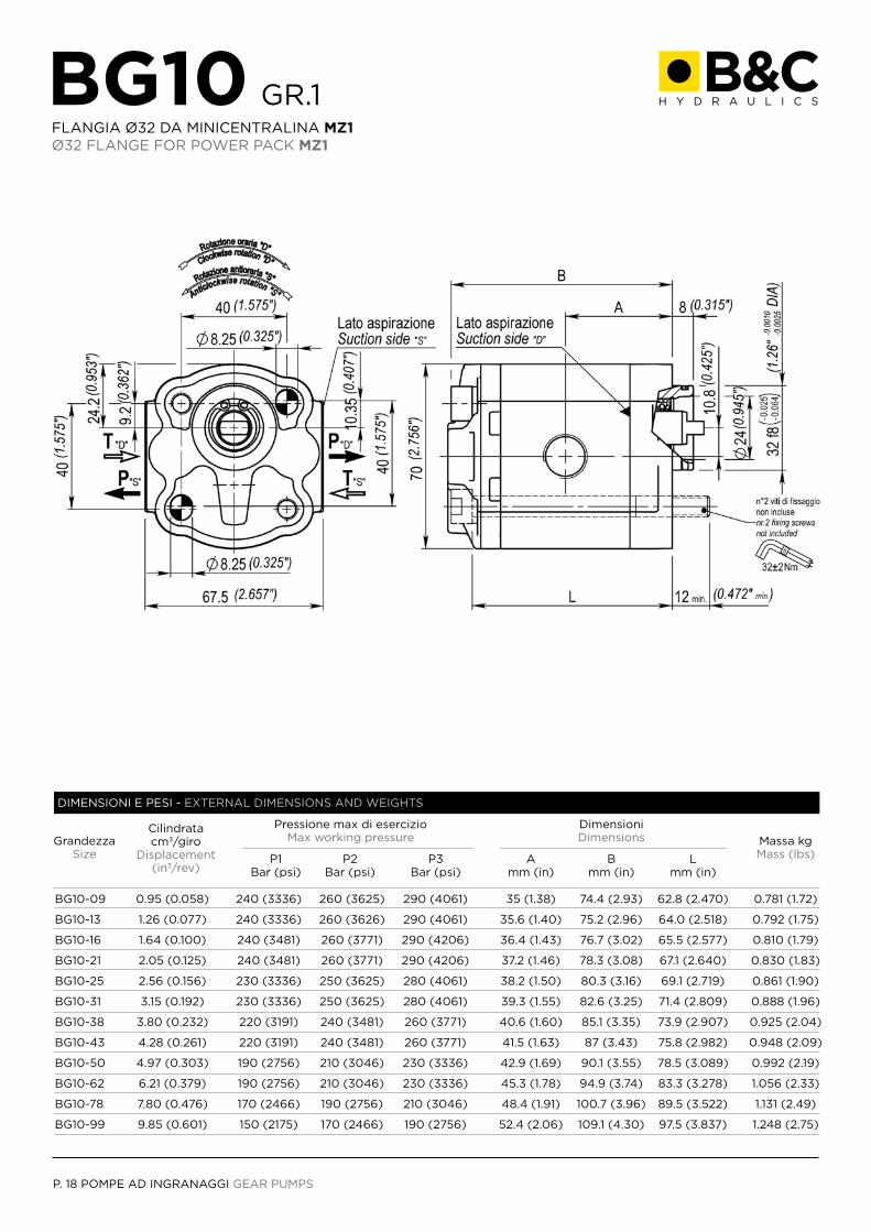
BG10 GR.1FLANGIA Ø32 DA MINICENTRALINA MZ1Ø32 FLANGE FOR POWER PACK MZ1
GrandezzaSize
Massa kgMass (lbs)
Cilindrata cm3/giro
Displacement(in3/rev)
DimensioniDimensions
BG10-09
BG10-13
BG10-16
BG10-21
BG10-25
BG10-31
BG10-38
BG10-43
BG10-50
BG10-62
BG10-78
BG10-99
0.95 (0.058)
1.26 (0.077)
1.64 (0.100)
2.05 (0.125)
2.56 (0.156)
3.15 (0.192)
3.80 (0.232)
4.28 (0.261)
4.97 (0.303)
6.21 (0.379)
7.80 (0.476)
9.85 (0.601)
240 (3336)
240 (3336)
240 (3481)
240 (3481)
230 (3336)
230 (3336)
220 (3191)
220 (3191)
190 (2756)
190 (2756)
170 (2466)
150 (2175)
260 (3625)
260 (3626)
260 (3771)
260 (3771)
250 (3625)
250 (3625)
240 (3481)
240 (3481)
210 (3046)
210 (3046)
190 (2756)
170 (2466)
290 (4061)
290 (4061)
290 (4206)
290 (4206)
280 (4061)
280 (4061)
260 (3771)
260 (3771)
230 (3336)
230 (3336)
210 (3046)
190 (2756)
35 (1.38)
35.6 (1.40)
36.4 (1.43)
37.2 (1.46)
38.2 (1.50)
39.3 (1.55)
40.6 (1.60)
41.5 (1.63)
42.9 (1.69)
45.3 (1.78)
48.4 (1.91)
52.4 (2.06)
74.4 (2.93)
75.2 (2.96)
76.7 (3.02)
78.3 (3.08)
80.3 (3.16)
82.6 (3.25)
85.1 (3.35)
87 (3.43)
90.1 (3.55)
94.9 (3.74)
100.7 (3.96)
109.1 (4.30)
62.8 (2.470)
64.0 (2.518)
65.5 (2.577)
67.1 (2.640)
69.1 (2.719)
71.4 (2.809)
73.9 (2.907)
75.8 (2.982)
78.5 (3.089)
83.3 (3.278)
89.5 (3.522)
97.5 (3.837)
0.781 (1.72)
0.792 (1.75)
0.810 (1.79)
0.830 (1.83)
0.861 (1.90)
0.888 (1.96)
0.925 (2.04)
0.948 (2.09)
0.992 (2.19)
1.056 (2.33)
1.131 (2.49)
1.248 (2.75)
Amm (in)
Pressione max di esercizioMax working pressure
P1Bar (psi)
P2Bar (psi)
P3Bar (psi)
Bmm (in)
Lmm (in)
DIMENSIONI E PESI - EXTERNAL DIMENSIONS AND WEIGHTS
POMPE AD INGRANAGGI GEAR PUMPS P. 19
0 Standard Standard
DS
A
MZ1
Rotazione destra Clockwise rotation Rotazione sinistra Anticlockwise rotation
Alluminio Aluminium
Flangia Ø32 da minicentralina Ø32 Flange for power pack
0V
Tenute in Nbr Nbr seals Tenute in Viton® Viton® seals
0.9509
EEx
2.5625
4.9750
1.6416
GG4
3.8038
7.8078
1.2613
TT4
3.1531
6.2162
2.0521
UUx
4.2843
9.8599
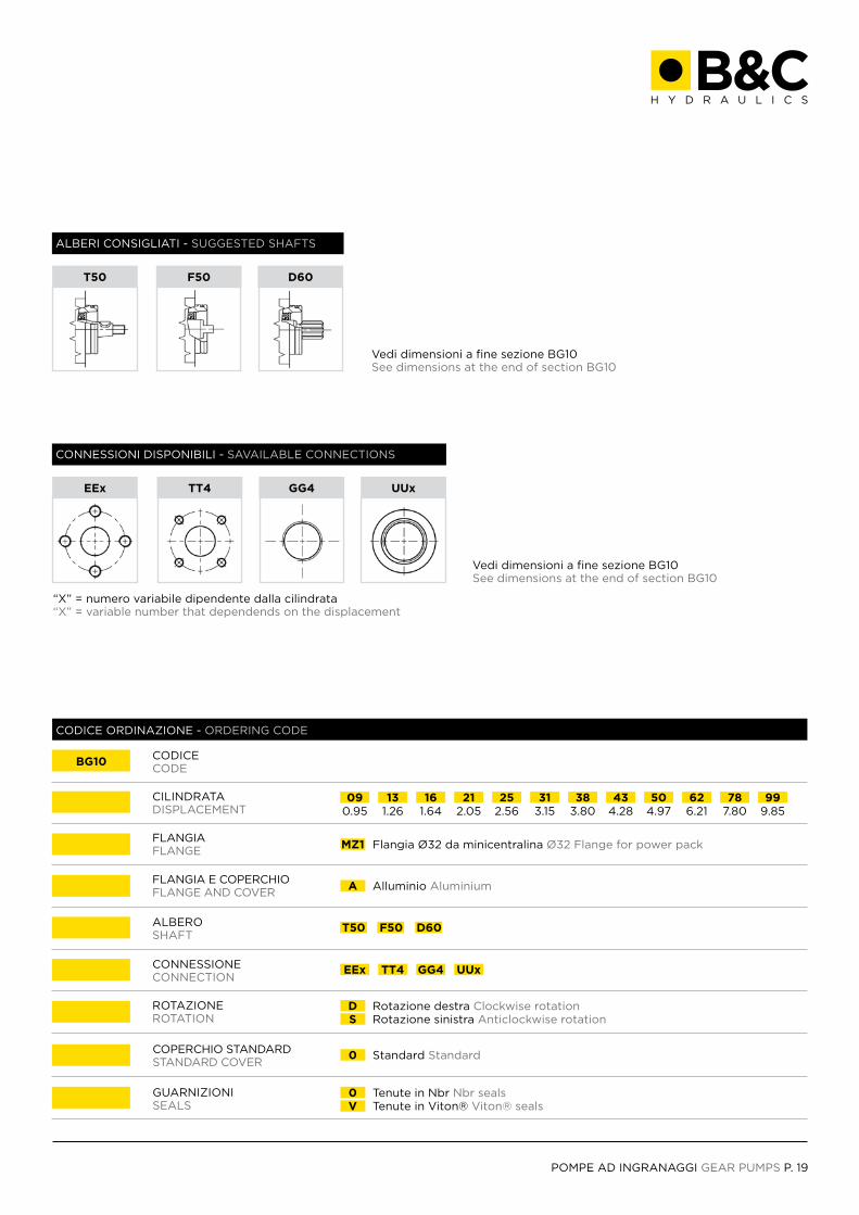
T50 F50 D60
COPERCHIO STANDARDSTANDARD COVER
CONNESSIONECONNECTION
CILINDRATADISPLACEMENT
CODICECODE
ALBEROSHAFT
ROTAZIONEROTATION
FLANGIA E COPERCHIOFLANGE AND COVER
FLANGIAFLANGE
GUARNIZIONISEALS
BG10
CODICE ORDINAZIONE - ORDERING CODE
ALBERI CONSIGLIATI - SUGGESTED SHAFTS
CONNESSIONI DISPONIBILI - SAVAILABLE CONNECTIONS
“X” = numero variabile dipendente dalla cilindrata“X” = variable number that dependends on the displacement
T50 F50 D60
EEx TT4 GG4 UUx
Vedi dimensioni a fine sezione BG10See dimensions at the end of section BG10
Vedi dimensioni a fine sezione BG10See dimensions at the end of section BG10
P. 20 POMPE AD INGRANAGGI GEAR PUMPS
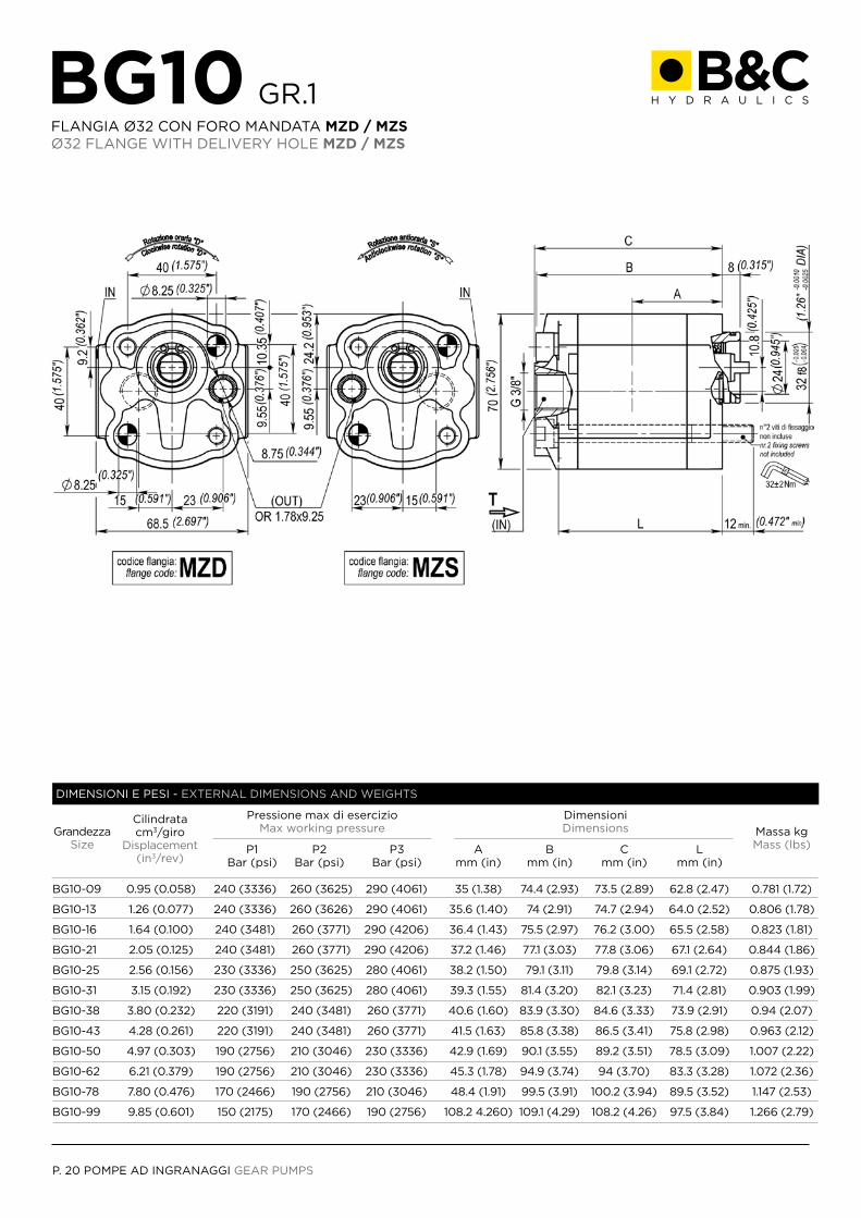
BG10 GR.1FLANGIA Ø32 CON FORO MANDATA MZD / MZSØ32 FLANGE WITH DELIVERY HOLE MZD / MZS
GrandezzaSize
Massa kgMass (lbs)
Cilindrata cm3/giro
Displacement(in3/rev)
DimensioniDimensions
BG10-09
BG10-13
BG10-16
BG10-21
BG10-25
BG10-31
BG10-38
BG10-43
BG10-50
BG10-62
BG10-78
BG10-99
0.95 (0.058)
1.26 (0.077)
1.64 (0.100)
2.05 (0.125)
2.56 (0.156)
3.15 (0.192)
3.80 (0.232)
4.28 (0.261)
4.97 (0.303)
6.21 (0.379)
7.80 (0.476)
9.85 (0.601)
240 (3336)
240 (3336)
240 (3481)
240 (3481)
230 (3336)
230 (3336)
220 (3191)
220 (3191)
190 (2756)
190 (2756)
170 (2466)
150 (2175)
260 (3625)
260 (3626)
260 (3771)
260 (3771)
250 (3625)
250 (3625)
240 (3481)
240 (3481)
210 (3046)
210 (3046)
190 (2756)
170 (2466)
290 (4061)
290 (4061)
290 (4206)
290 (4206)
280 (4061)
280 (4061)
260 (3771)
260 (3771)
230 (3336)
230 (3336)
210 (3046)
190 (2756)
35 (1.38)
35.6 (1.40)
36.4 (1.43)
37.2 (1.46)
38.2 (1.50)
39.3 (1.55)
40.6 (1.60)
41.5 (1.63)
42.9 (1.69)
45.3 (1.78)
48.4 (1.91)
108.2 4.260)
74.4 (2.93)
74 (2.91)
75.5 (2.97)
77.1 (3.03)
79.1 (3.11)
81.4 (3.20)
83.9 (3.30)
85.8 (3.38)
90.1 (3.55)
94.9 (3.74)
99.5 (3.91)
109.1 (4.29)
73.5 (2.89)
74.7 (2.94)
76.2 (3.00)
77.8 (3.06)
79.8 (3.14)
82.1 (3.23)
84.6 (3.33)
86.5 (3.41)
89.2 (3.51)
94 (3.70)
100.2 (3.94)
108.2 (4.26)
62.8 (2.47)
64.0 (2.52)
65.5 (2.58)
67.1 (2.64)
69.1 (2.72)
71.4 (2.81)
73.9 (2.91)
75.8 (2.98)
78.5 (3.09)
83.3 (3.28)
89.5 (3.52)
97.5 (3.84)
0.781 (1.72)
0.806 (1.78)
0.823 (1.81)
0.844 (1.86)
0.875 (1.93)
0.903 (1.99)
0.94 (2.07)
0.963 (2.12)
1.007 (2.22)
1.072 (2.36)
1.147 (2.53)
1.266 (2.79)
Amm (in)
Pressione max di esercizioMax working pressure
P1Bar (psi)
P2Bar (psi)
P3Bar (psi)
Bmm (in)
Cmm (in)
Lmm (in)
DIMENSIONI E PESI - EXTERNAL DIMENSIONS AND WEIGHTS
POMPE AD INGRANAGGI GEAR PUMPS P. 21
01
Standard StandardAspirazione su coperchio Suction on the cover
0
0
DS
A
MZDMZS
Corpo senza mandata Body without delivery
Corpo senza aspirazione Body without suction
Aspirazione su corpo Suction on the body
Rotazione destra (solo MZD) Clockwise rotation (only MZD)Rotazione sinistra (solo MZS) Anticlockwise rotation (only MZS)
Alluminio Aluminium
Minicentralina destra con foro mandata With delivery hole for right power packMinicentralina sinistra con foro mandata With delivery hole for left power pack
0V
Tenute in Nbr Nbr seals Tenute in Viton® Viton® seals
0.9509
EEx
2.5625
4.9750
1.6416
GG4
3.8038
7.8078
1.2613
TT4
3.1531
6.2162
2.0521
EG
TU
UUx 000
4.2843
9.8599
T50 F50 D60
COPERCHIO STANDARDSTANDARD COVER
CONNESSIONE ASPIRAZIONESUCTION CONNECTION
CONNESSIONECONNECTION
CILINDRATADISPLACEMENT
CODICECODE
ALBEROSHAFT
CONNESSIONE MANDATADELIVERY CONNECTION
ROTAZIONEROTATION
FLANGIA E COPERCHIOFLANGE AND COVER
FLANGIAFLANGE
GUARNIZIONISEALS
BG10
CODICE ORDINAZIONE - ORDERING CODE
ALBERI CONSIGLIATI - SUGGESTED SHAFTS
CONNESSIONI DISPONIBILI - SAVAILABLE CONNECTIONS
“X” = numero variabile dipendente dalla cilindrata“X” = variable number that dependends on the displacement
F50 T50 D60
EEx TT4 GG4 UUx 000
COPERCHI DISPONIBILI - AVAILABLE COVERS
0 1
Vedi dimensioni a fine sezione BG10See dimensions at the end of section BG10
Vedi dimensioni a fine sezione BG10See dimensions at the end of section BG10
Vedi dimensioni a fine sezione BG10See dimensions at the end of section BG10
P. 22 POMPE AD INGRANAGGI GEAR PUMPS
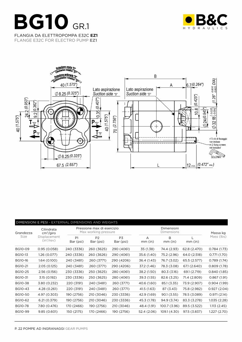
BG10 GR.1FLANGIA DA ELETTROPOMPA E32C EZ1FLANGE E32C FOR ELECTRO PUMP EZ1
GrandezzaSize
Massa kgMass (lbs)
Cilindrata cm3/giro
Displacement(in3/rev)
DimensioniDimensions
BG10-09
BG10-13
BG10-16
BG10-21
BG10-25
BG10-31
BG10-38
BG10-43
BG10-50
BG10-62
BG10-78
BG10-99
0.95 (0.058)
1.26 (0.077)
1.64 (0.100)
2.05 (0.125)
2.56 (0.156)
3.15 (0.192)
3.80 (0.232)
4.28 (0.261)
4.97 (0.303)
6.21 (0.379)
7.80 (0.476)
9.85 (0.601)
240 (3336)
240 (3336)
240 (3481)
240 (3481)
230 (3336)
230 (3336)
220 (3191)
220 (3191)
190 (2756)
190 (2756)
170 (2466)
150 (2175)
260 (3625)
260 (3626)
260 (3771)
260 (3771)
250 (3625)
250 (3625)
240 (3481)
240 (3481)
210 (3046)
210 (3046)
190 (2756)
170 (2466)
290 (4061)
290 (4061)
290 (4206)
290 (4206)
280 (4061)
280 (4061)
260 (3771)
260 (3771)
230 (3336)
230 (3336)
210 (3046)
190 (2756)
35 (1.38)
35.6 (1.40)
36.4 (1.43)
37.2 (1.46)
38.2 (1.50)
39.3 (1.55)
40.6 (1.60)
41.5 (1.63)
42.9 (1.69)
45.3 (1.78)
48.4 (1.91)
52.4 (2.06)
74.4 (2.93)
75.2 (2.96)
76.7 (3.02)
78.3 (3.08)
80.3 (3.16)
82.6 (3.25)
85.1 (3.35)
87 (3.43)
90.1 (3.55)
94.9 (3.74)
100.7 (3.96)
109.1 (4.30)
62.8 (2.470)
64.0 (2.518)
65.5 (2.577)
67.1 (2.640)
69.1 (2.719)
71.4 (2.809)
73.9 (2.907)
75.8 (2.982)
78.5 (3.089)
83.3 (3.278)
89.5 (3.522)
97.5 (3.837)
0.784 (1.73)
0.771 (1.70)
0.789 (1.74)
0.809 (1.78)
0.840 (1.85)
0.867 (1.91)
0.904 (1.99)
0.927 (2.04)
0.971 (2.14)
1.035 (2.28)
1.113 (2.45)
1.227 (2.70)
Amm (in)
Pressione max di esercizioMax working pressure
P1Bar (psi)
P2Bar (psi)
P3Bar (psi)
Bmm (in)
Lmm (in)
DIMENSIONI E PESI - EXTERNAL DIMENSIONS AND WEIGHTS
POMPE AD INGRANAGGI GEAR PUMPS P. 23
0 Standard Standard
DS
A
EZ1
Rotazione destra Clockwise rotation Rotazione sinistra Anticlockwise rotation
Alluminio Aluminium
E32c da elettropompa E32c for electro pump
0V
Tenute in Nbr Nbr seals Tenute in Viton® Viton® seals
3 Con giunto With coupling
0.9509
EEx
2.5625
4.9750
1.6416
GG4
3.8038
7.8078
1.2613
TT4
3.1531
6.2162
2.0521
UUx
4.2843
9.8599
E50
COPERCHIO STANDARDSTANDARD COVER
CONNESSIONECONNECTION
CILINDRATADISPLACEMENT
CODICECODE
ALBEROSHAFT
ROTAZIONEROTATION
FLANGIA E COPERCHIOFLANGE AND COVER
FLANGIAFLANGE
GUARNIZIONISEALS
ACCESSORIOPTIONALS
BG10
CODICE ORDINAZIONE - ORDERING CODE
ALBERI CONSIGLIATI - SUGGESTED SHAFTS
CONNESSIONI DISPONIBILI - SAVAILABLE CONNECTIONS
“X” = numero variabile dipendente dalla cilindrata“X” = variable number that dependends on the displacement
E50
EEx TT4 GG4 UUx
Vedi dimensioni a fine sezione BG10See dimensions at the end of section BG10
Vedi dimensioni a fine sezione BG10See dimensions at the end of section BG10
P. 24 POMPE AD INGRANAGGI GEAR PUMPS
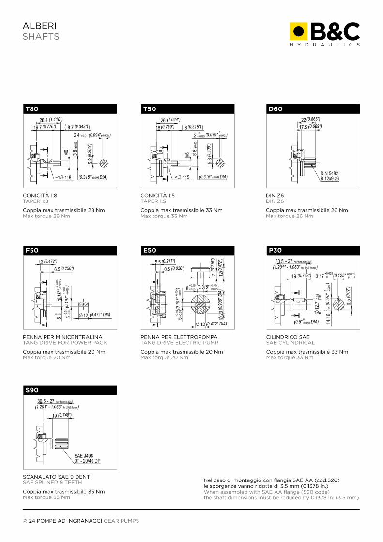
ALBERISHAFTS
Coppia max trasmissibile 20 NmMax torque 20 Nm
Coppia max trasmissibile 28 NmMax torque 28 Nm
Coppia max trasmissibile 33 NmMax torque 33 Nm
Coppia max trasmissibile 20 NmMax torque 20 Nm
Coppia max trasmissibile 33 NmMax torque 33 Nm
Coppia max trasmissibile 26 NmMax torque 26 Nm
F50
T80 T50
E50 P30
D60
PENNA PER MINICENTRALINATANG DRIVE FOR POWER PACK
Coppia max trasmissibile 35 NmMax torque 35 Nm
Nel caso di montaggio con flangia SAE AA (cod.S20) le sporgenze vanno ridotte di 3.5 mm (0.1378 In.)When assembled with SAE AA flange (S20 code) the shaft dimensions must be reduced by 0.1378 In. (3.5 mm)
S90
SCANALATO SAE 9 DENTISAE SPLINED 9 TEETH
CONICITÀ 1:8TAPER 1:8
CONICITÀ 1:5TAPER 1:5
PENNA PER ELETTROPOMPATANG DRIVE ELECTRIC PUMP
CILINDRICO SAESAE CYLINDRICAL
DIN Z6DIN Z6
POMPE AD INGRANAGGI GEAR PUMPS P. 25
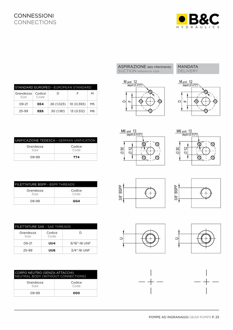
CONNESSIONICONNECTIONS
ASPIRAZIONE lato riferimento
SUCTION reference side
MANDATADELIVERY
GrandezzaSize
09-21
25-99
GrandezzaSize
09-99
GrandezzaSize
09-99
GrandezzaSize
09-99
CodiceCode
UU4
UU6
CodiceCode
TT4
CodiceCode
GG4
CodiceCode
000
D
9/16”-18 UNF
3/4”-16 UNF
GrandezzaSize
09-21
25-99
CodiceCode
EE4
EE6
D
26 (1.023)
30 (1.181)
F
10 (0.393)
13 (0.512)
M
M5
M6
STANDARD EUROPEO - EUROPEAN STANDARD
FILETTATURE SAE - SAE THREADS
UNIFICAZIONE TEDESCA - GERMAN UNIFICATION
FILETTATURE BSPP - BSPP THREADS
CORPO NEUTRO (SENZA ATTACCHI)NEUTRAL BODY (WITHOUT CONNECTIONS)
3/8’
’ BSP
P
3/8’
’ BSP
P
P. 26 POMPE AD INGRANAGGI GEAR PUMPS
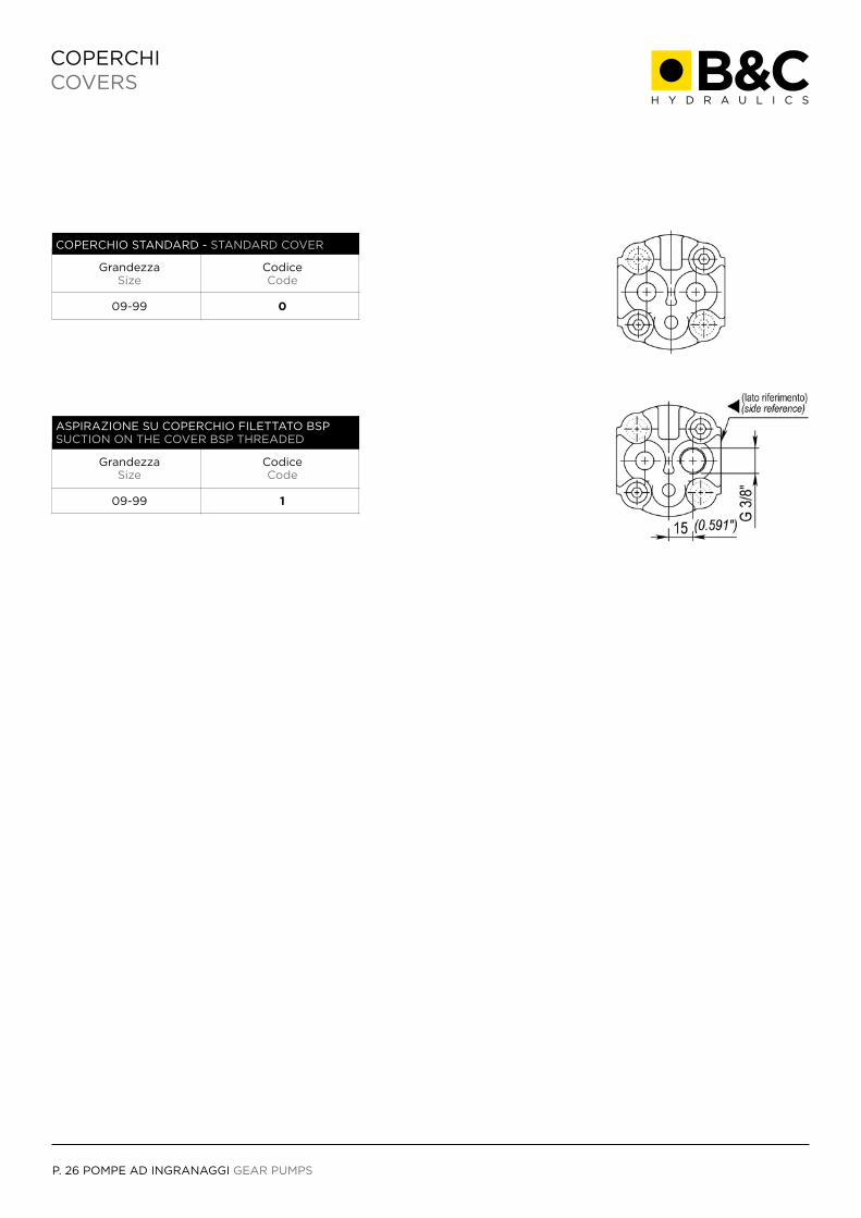
COPERCHICOVERS
GrandezzaSize
09-99
CodiceCode
0
COPERCHIO STANDARD - STANDARD COVER
GrandezzaSize
09-99
CodiceCode
1
ASPIRAZIONE SU COPERCHIO FILETTATO BSPSUCTION ON THE COVER BSP THREADED
B & C S.r.l Via Panizzi, 3 - 42011 Bagnolo in Piano (RE), Italy
Tel. +39 0522 951353 - Fax +39 0522 [email protected] - www.bcit.it

www.bcit.it