
MOBILE CONTENT DELIVERY NETWORK DESIGN ... -...
93
Universit` a degli studi di Padova Dipartimento di Ingegneria dell’Informazione Corso di Laurea Magistrale in Ingegneria delle Telecomunicazioni TESI DI LAUREA MOBILE CONTENT DELIVERY NETWORK DESIGN AND IMPLEMENTATION RELATORE: Prof. Michele Zorzi CORRELATORI: Daniele Munaretto, Gerald Kunzmann LAUREANDO: Alberto Desider` a Padova, 15 luglio 2013
Transcript of MOBILE CONTENT DELIVERY NETWORK DESIGN ... -...
Universita degli studi di Padova
Dipartimento di Ingegneria dell’Informazione
Corso di Laurea Magistrale in
Ingegneria delle Telecomunicazioni
TESI DI LAUREA
MOBILE CONTENT DELIVERY
NETWORK DESIGN AND
IMPLEMENTATION
RELATORE: Prof. Michele Zorzi
CORRELATORI: Daniele Munaretto, Gerald Kunzmann
LAUREANDO: Alberto Desidera
Padova, 15 luglio 2013

ii
Nessuno effetto e in natura sanza ragione;
intendi la ragione e non ti bisogna sperienza.
(Leonardo da Vinci)

iv
Contents
Abstract 1
1 Introduction 3
2 Mobile video delivery architecture 5
2.1 Services and global requirements . . . . . . . . . . . . . . . . . . . 5
2.2 Functional architecture . . . . . . . . . . . . . . . . . . . . . . . . 7
2.2.1 Video service control, wireless access and mobility manage-
ment . . . . . . . . . . . . . . . . . . . . . . . . . . . . . . 7
2.2.2 Transport optimisation . . . . . . . . . . . . . . . . . . . . 8
2.3 Network topology . . . . . . . . . . . . . . . . . . . . . . . . . . . 12
3 MCDN description 13
3.1 Design . . . . . . . . . . . . . . . . . . . . . . . . . . . . . . . . . 15
3.2 Features . . . . . . . . . . . . . . . . . . . . . . . . . . . . . . . . 18
3.3 Interfaces . . . . . . . . . . . . . . . . . . . . . . . . . . . . . . . 18
4 MCDN implementation 21
4.1 Requirements . . . . . . . . . . . . . . . . . . . . . . . . . . . . . 21
4.2 Entities . . . . . . . . . . . . . . . . . . . . . . . . . . . . . . . . 23
4.2.1 Core Router . . . . . . . . . . . . . . . . . . . . . . . . . . 23
4.2.2 Node . . . . . . . . . . . . . . . . . . . . . . . . . . . . . . 25
4.2.3 Origin . . . . . . . . . . . . . . . . . . . . . . . . . . . . . 35
4.2.4 Portal . . . . . . . . . . . . . . . . . . . . . . . . . . . . . 37
4.3 Interfaces . . . . . . . . . . . . . . . . . . . . . . . . . . . . . . . 42
4.4 Real testbed implementation . . . . . . . . . . . . . . . . . . . . . 43
v
5 Results 47
5.1 Segmented videos and request routing . . . . . . . . . . . . . . . . 47
5.2 Popularity-based caching . . . . . . . . . . . . . . . . . . . . . . . 50
5.3 Robustness of the CDN component . . . . . . . . . . . . . . . . . 52
5.4 Session continuity during handovers . . . . . . . . . . . . . . . . . 53
5.5 Wireshark captures . . . . . . . . . . . . . . . . . . . . . . . . . . 55
5.6 Practical scenarios . . . . . . . . . . . . . . . . . . . . . . . . . . 59
5.7 Experimental results . . . . . . . . . . . . . . . . . . . . . . . . . 60
6 Conclusions 67
A Functional architecture: details 73
A.1 Video Services Control . . . . . . . . . . . . . . . . . . . . . . . . 73
A.2 Wireless Access . . . . . . . . . . . . . . . . . . . . . . . . . . . . 75
A.3 Mobility Management . . . . . . . . . . . . . . . . . . . . . . . . 76
Bibliography 80
vi
List of Abbreviations
ALTO Application-Layer Traffic Optimisation
AM Application Manager (component / module)
AN Access Network
CDN Content Delivery Network (component / module)
CDNNC CDN Node Control (component / module)
CN Core Network
DASH Dynamic Adaptive Streaming over HTTP
DM Decision Manager (component / module)
FM Flow Manager (component / module)
HA Home Agent
HoA Home Address
IEEE The Institute of Electrical and Electronics Engineers
IETF The Internet Engineering Task Force
LMA Local Mobility Anchor
LMD Localized Mobility Domain
LTE Long Term Evolution
MAC Medium Access Control
MAG Mobile Access Gateway
MAR Mobile Access Router
MCDN Mobile Content Delivery Network
MEDIEVAL MultimEDia transport for mobIlE Video AppLications
MIPv6 Mobile IPv6
MM Mobility Management (component / module)
vii
MN Mobile Node
MTU Maximum Transmission Unit
NAT Network Address Translation
NO Network Operator
PMIPv6 Proxy Mobile IPv6
PoA Point of Attachment
QoE Quality of Experience
QoS Quality of Service
TO Transport Optimisation (component / module)
VoD Video on Demand
VoIP Voice over IP
VSC Video Service Control (component / module)
WA Wireless Access (component / module)
XLO Cross-Layer Optimisation (module)
viii
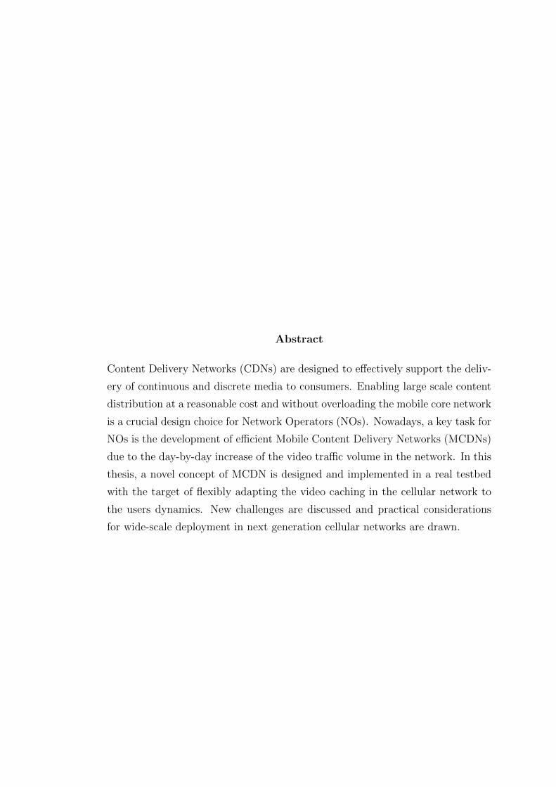
Abstract
Content Delivery Networks (CDNs) are designed to effectively support the deliv-
ery of continuous and discrete media to consumers. Enabling large scale content
distribution at a reasonable cost and without overloading the mobile core network
is a crucial design choice for Network Operators (NOs). Nowadays, a key task for
NOs is the development of efficient Mobile Content Delivery Networks (MCDNs)
due to the day-by-day increase of the video traffic volume in the network. In this
thesis, a novel concept of MCDN is designed and implemented in a real testbed
with the target of flexibly adapting the video caching in the cellular network to
the users dynamics. New challenges are discussed and practical considerations
for wide-scale deployment in next generation cellular networks are drawn.

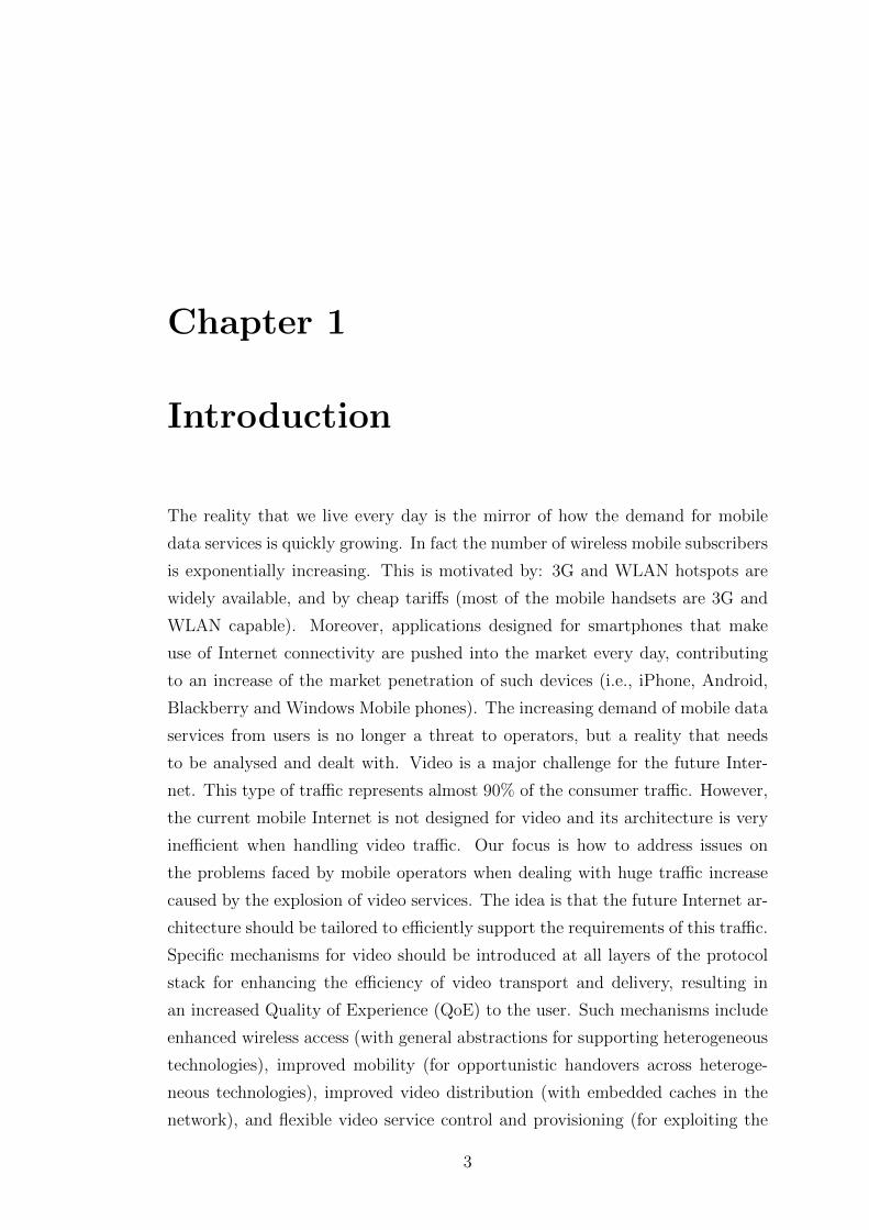
Chapter 1
Introduction
The reality that we live every day is the mirror of how the demand for mobile
data services is quickly growing. In fact the number of wireless mobile subscribers
is exponentially increasing. This is motivated by: 3G and WLAN hotspots are
widely available, and by cheap tariffs (most of the mobile handsets are 3G and
WLAN capable). Moreover, applications designed for smartphones that make
use of Internet connectivity are pushed into the market every day, contributing
to an increase of the market penetration of such devices (i.e., iPhone, Android,
Blackberry and Windows Mobile phones). The increasing demand of mobile data
services from users is no longer a threat to operators, but a reality that needs
to be analysed and dealt with. Video is a major challenge for the future Inter-
net. This type of traffic represents almost 90% of the consumer traffic. However,
the current mobile Internet is not designed for video and its architecture is very
inefficient when handling video traffic. Our focus is how to address issues on
the problems faced by mobile operators when dealing with huge traffic increase
caused by the explosion of video services. The idea is that the future Internet ar-
chitecture should be tailored to efficiently support the requirements of this traffic.
Specific mechanisms for video should be introduced at all layers of the protocol
stack for enhancing the efficiency of video transport and delivery, resulting in
an increased Quality of Experience (QoE) to the user. Such mechanisms include
enhanced wireless access (with general abstractions for supporting heterogeneous
technologies), improved mobility (for opportunistic handovers across heteroge-
neous technologies), improved video distribution (with embedded caches in the
network), and flexible video service control and provisioning (for exploiting the
3
interactions with video applications). In particular we focus our efforts on the
transport optimization aspects regarding the video distribution and the mobility
management. We study critical aspects to be tackled and we propose a solution
which involves the negotiation of resource allocations at the wireless access and
implements optimal handover decisions based on the mobility module. MCDN is
designed to enhance video transport via caching strategies specifically designed
for enhancing the video performance and takes into account the environment of
the entire system is the mobility. MCDN integrates mobile delivery services that
optimize the transport of several contents including live video streaming, video
on demand and delivery of content assets. The purpose of our work is to design
and to implement a MCDN tailored to the challenging world of the mobile video
traffic over next generation cellular networks.
We want to remind the reader that the technology developed takes into account
the requirements of NOs for commercial deployment, and aims at improving the
QoE of users as well as reducing the costs for operators. Moreover, the technology
is implemented in a testbed that serves as a proof of concept as well as a basis
for future commercial deployments.
The thesis is organized as follows:
• Chapter 2 summarizes the Mobile Video Delivery general architecture, with
a detailed description of mobility aspects and enhanced wireless access;
• Chapter 3 introduces the concept of MCDN, the main topic of this thesis,
justifying our design choice and listing the aspects required for the devel-
opment of it. Then we list the functionalities required to make it work
properly within the cellular system;
• Chapter 4 discusses the technological requirements and how our solution
is implemented focusing on the entities and the system behaviour. It also
introduces a description of the demo implementation;
• Chapter 5 gives some results about the performance of our framework;
• Chapter 6 concludes the thesis highlighting the learned lessons and drawing
research directions for future work.
4
Chapter 2
Mobile video delivery
architecture
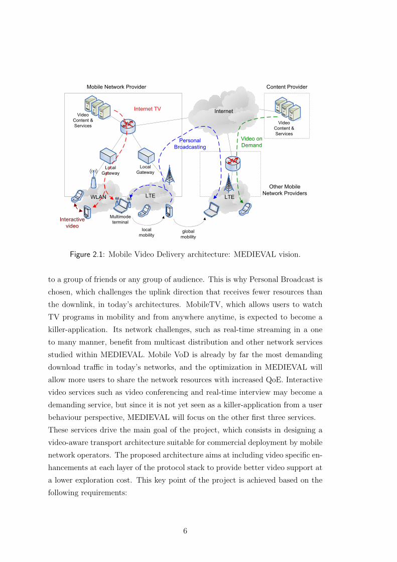
The mobile video delivery system we consider is taken form the FP7 European
funded project MEDIEVAL (MultiMEDia transport for mobIlE Video AppLica-
tions) [1]. Figure 2.1, see [2], shows MEDIEVAL’s vision, which aims at evolving
the Internet architecture for efficient video transport. The proposed architecture
follows a cross-layer design that, by exploiting the interaction between layers, can
increase the performance to values unattainable with individual developments [2].
Next, we briefly describe the MEDIEVAL architecture, to which we refer from
now on as our mobile video delivery architecture.
2.1 Services and global requirements
As for Figure 2.1, the MEDIEVAL services refer to a list of challenging user ser-
vices which are expected to dominate the traffic over the wireless networks in
the near future. In particular four types of services are chosen, which together
complete one another and would lead the technology development in the right
direction. In particular the typologies of video are the following: Personal Broad-
cast, MobileTV, Mobile Video on Demand (VoD) and Interactive Video, and in
the following we say what we mean by each of them.
The trend of user generated video content is now penetrating the social networks
such as Facebook, Twitter and others, where users are able to stream live content
5
Technical ApproachThe key components of the MEDIEVAL architecture are illustrated in the figure on the right. The proposed architecture comprises the following five key functionalities: • Interaction with the underlying network
mechanisms to allow video services optimally customise the network behaviour.
• Enhanced wireless access to optimise video performance by exploiting the features of each available wireless technology.
• Novel dynamic mobility architecture for next generation mobile networks adapted to video service requirements.
• Optimisation of the video transport by means of Quality of Experience driven network mechanisms, including caching and network support for P2P video streaming.
• Support for broadcast and multicast video services by introducing multicast mechanisms at different layers of the protocol stack.
LTE
Internet
LTEWLAN
LocalGateway
LocalGateway
Mobile Network Provider
VideoContent & Services
Other MobileNetwork Providers
Internet TV
PersonalBroadcasting
localmobility
globalmobility
Multimodeterminal
Video onDemand
Interactivevideo
VideoContent & Services
Content Provider
MEDIEVAL vision
Key Issues The proposed architecture will address the following five key issues: • Specification of an interface between the
video services and the underlying network mechanisms.
• Enhanced wireless access to optimise video performance.
• Design of a novel dynamic mobility architecture adapted to video service requirements.
• Optimisation of the video delivery by means of Quality of Experience (QoE) driven network mechanisms.
• Support for broadcast and multicast video services, including Internet TV and Personal Broadcasting.
Expected Impact Video services are a very promising business case. One key goal of the project is to propose an operator-driven architecture, resulting in an integrated video solution that can be implemented by an operator and offered to its customers. The research conducted in MEDIEVAL will also aim at strengthening current mobile core and video solutions, resulting in both IPR generation (when applicable) as well as dissemination of these results in prestigious scientific fora. The project will follow and contribute to the main standardisation bodies such as 3GPP, IETF and IEEE, which have already detected the need for video enhancements.
MEDIEVAL October 2010
Figure 2.1: Mobile Video Delivery architecture: MEDIEVAL vision.
to a group of friends or any group of audience. This is why Personal Broadcast is
chosen, which challenges the uplink direction that receives fewer resources than
the downlink, in today’s architectures. MobileTV, which allows users to watch
TV programs in mobility and from anywhere anytime, is expected to become a
killer-application. Its network challenges, such as real-time streaming in a one
to many manner, benefit from multicast distribution and other network services
studied within MEDIEVAL. Mobile VoD is already by far the most demanding
download traffic in today’s networks, and the optimization in MEDIEVAL will
allow more users to share the network resources with increased QoE. Interactive
video services such as video conferencing and real-time interview may become a
demanding service, but since it is not yet seen as a killer-application from a user
behaviour perspective, MEDIEVAL will focus on the other first three services.
These services drive the main goal of the project, which consists in designing a
video-aware transport architecture suitable for commercial deployment by mobile
network operators. The proposed architecture aims at including video specific en-
hancements at each layer of the protocol stack to provide better video support at
a lower exploration cost. This key point of the project is achieved based on the
following requirements:
6
• Improve the user experience by allowing the video services to optimally
customize the network behaviour;
• Optimize the video performance by enhancing the features of the available
wireless accesses in coordination with the video services;
• Design a novel dynamic architecture for next generation mobile networks
tailored to the proposed video services;
• Perform a transport optimization of the video by means of QoE driven
network mechanisms, including MCDN techniques, which represent the core
of this work;
• Introduce multicast mechanisms at different layers of the protocol stack to
provide both broadcast and multicast video services, including Mobile
TV and Personal Broadcast.
2.2 Functional architecture
Next we present the overall design of the MEDIEVAL architecture to satisfy the
requirements identified previously. Hence, we introduce the description of the
subsystems that compose the four main blocks of the architecture: the Video
Services Control (VSC) subsystem, the Wireless Access (WA) subsystem, the
Mobility Management (MM) subsystem and the Transport Optimization (TO)
subsystem. In the next section we briefly describe the first three and we focus
more on TO subsystem. The global architecture with the functions comprised by
a MEDIEVAL network is depicted in Figure 2.2, taken from [2].
2.2.1 Video service control, wireless access and mobility
management
The video service control component is in charge of linking video services to the
underlying network delivery entities. It aims at enabling a reliable video delivery
chain over an evolved mobile network, which offers improved resources utilisation
and an enhanced user experience. To do this, a cross-layer set of interfaces are
built to make the components interact. This approach bridges the applications
to an improved network allowing video contents to be delivered to groups of users
7
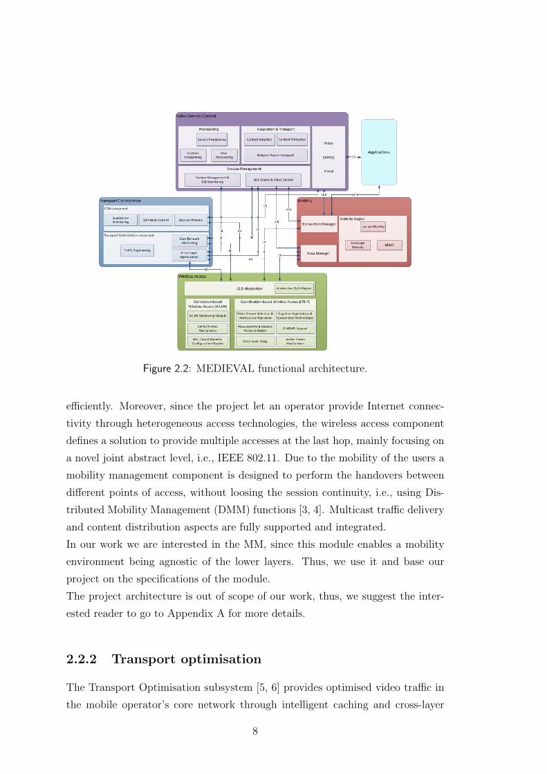
Figure 2.2: MEDIEVAL functional architecture.
efficiently. Moreover, since the project let an operator provide Internet connec-
tivity through heterogeneous access technologies, the wireless access component
defines a solution to provide multiple accesses at the last hop, mainly focusing on
a novel joint abstract level, i.e., IEEE 802.11. Due to the mobility of the users a
mobility management component is designed to perform the handovers between
different points of access, without loosing the session continuity, i.e., using Dis-
tributed Mobility Management (DMM) functions [3, 4]. Multicast traffic delivery
and content distribution aspects are fully supported and integrated.
In our work we are interested in the MM, since this module enables a mobility
environment being agnostic of the lower layers. Thus, we use it and base our
project on the specifications of the module.
The project architecture is out of scope of our work, thus, we suggest the inter-
ested reader to go to Appendix A for more details.
2.2.2 Transport optimisation
The Transport Optimisation subsystem [5, 6] provides optimised video traffic in
the mobile operator’s core network through intelligent caching and cross-layer
8
interactions. The main objective is two-fold: 1) reduce the load of the operator’s
backbone, 2) while still providing a satisfactory QoE to the users.
The first goal is addressed by establishing a MCDN, with a special focus on
the selection of optimal cache locations and node selection based on costs like
‘network distance’. This means that MEDIEVAL aims at service placement (i.e.,
finding optimal locations for deploying the CDN nodes considering, various cost
metrics, the design of the core network and operator policies), content placement
(i.e., the optimal distribution of content among the CDN nodes), and content
routing (i.e., choosing from the set of CDN nodes, providing the desired content,
the node or subset of nodes that minimises streaming costs).
The second goal is addressed by providing proper optimised resource allocation
and traffic engineering techniques in order to increase as much as possible the user
perceived quality (QoE) within the given resources in the network. Therefore,
the system performance is evaluated in a network-wide context using cross-layer
optimisation techniques. Information is collected from the other MEDIEVAL
subsystems, like MAC and buffer states from the Wireless Access, QoE-based
data about video sensitivity from the Video Services, and handover candidates
from the Mobility subsystem.
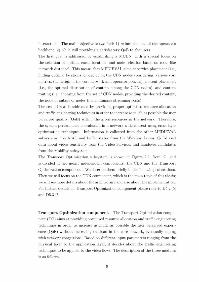
The Transport Optimisation subsystem is shown in Figure 2.3, from [2], and
is divided in two nearly independent components: the CDN and the Transport
Optimization components. We describe them briefly in the following subsections.
Then we will focus on the CDN component, which is the main topic of this thesis;
we will see more details about the architecture and also about the implementation.
For further details on Transport Optimization component please refer to D5.2 [5]
and D5.3 [7].
Transport Optimization component. The Transport Optimisation compo-
nent (TO) aims at providing optimised resource allocation and traffic engineering
techniques in order to increase as much as possible the user perceived experi-
ence (QoE) without increasing the load in the core network, eventually coping
with network congestions. Based on different input parameters ranging from the
physical layer to the application layer, it decides about the traffic engineering
techniques to be applied to the video flows. The description of the three modules
is as follows:
9
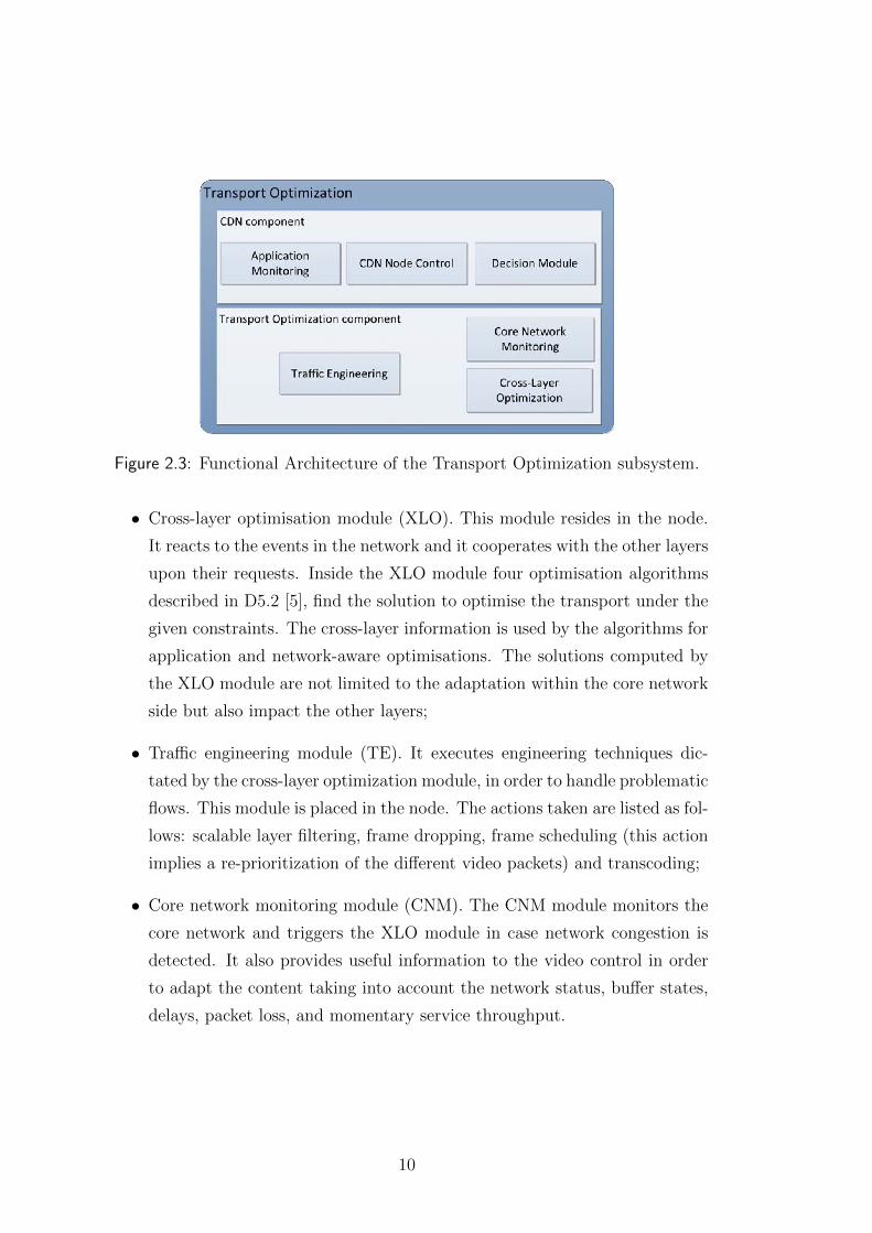
Figure 2.3: Functional Architecture of the Transport Optimization subsystem.
• Cross-layer optimisation module (XLO). This module resides in the node.
It reacts to the events in the network and it cooperates with the other layers
upon their requests. Inside the XLO module four optimisation algorithms
described in D5.2 [5], find the solution to optimise the transport under the
given constraints. The cross-layer information is used by the algorithms for
application and network-aware optimisations. The solutions computed by
the XLO module are not limited to the adaptation within the core network
side but also impact the other layers;
• Traffic engineering module (TE). It executes engineering techniques dic-
tated by the cross-layer optimization module, in order to handle problematic
flows. This module is placed in the node. The actions taken are listed as fol-
lows: scalable layer filtering, frame dropping, frame scheduling (this action
implies a re-prioritization of the different video packets) and transcoding;
• Core network monitoring module (CNM). The CNM module monitors the
core network and triggers the XLO module in case network congestion is
detected. It also provides useful information to the video control in order
to adapt the content taking into account the network status, buffer states,
delays, packet loss, and momentary service throughput.
10
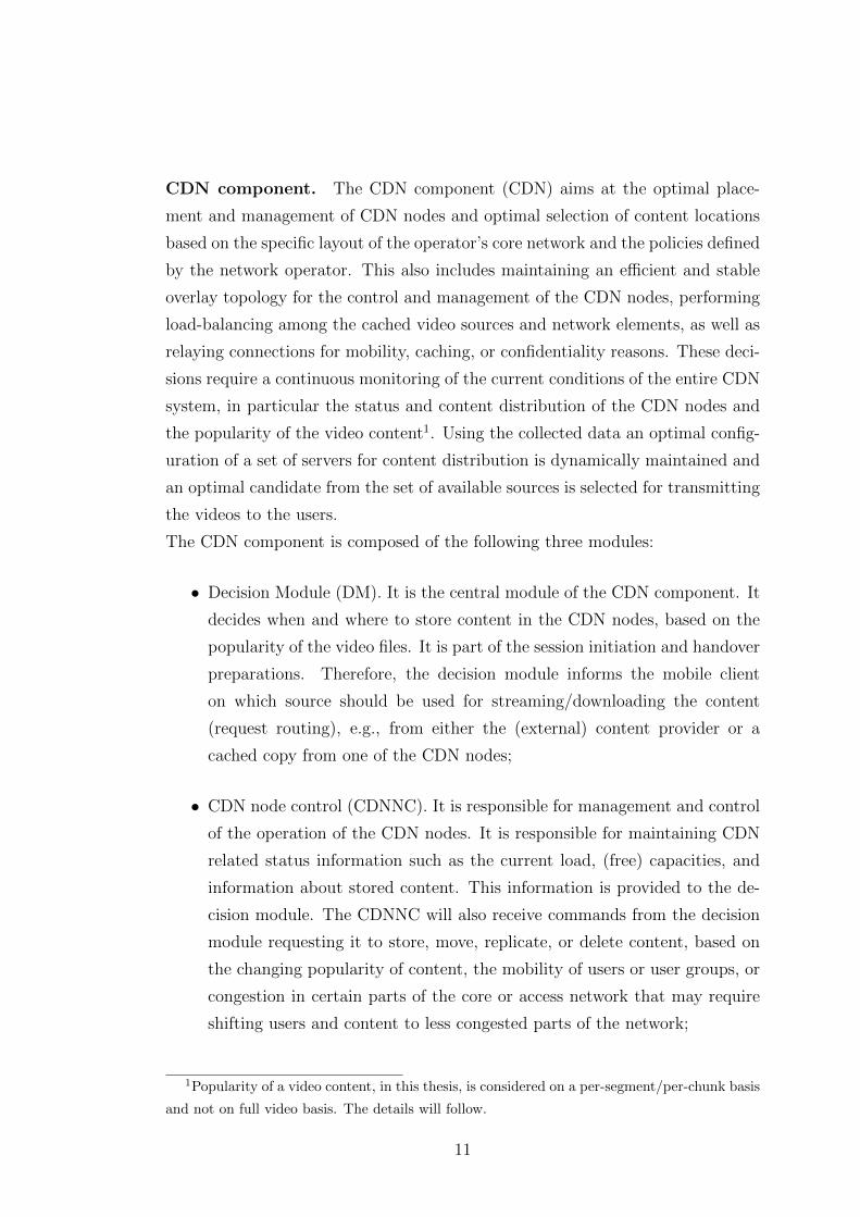
CDN component. The CDN component (CDN) aims at the optimal place-
ment and management of CDN nodes and optimal selection of content locations
based on the specific layout of the operator’s core network and the policies defined
by the network operator. This also includes maintaining an efficient and stable
overlay topology for the control and management of the CDN nodes, performing
load-balancing among the cached video sources and network elements, as well as
relaying connections for mobility, caching, or confidentiality reasons. These deci-
sions require a continuous monitoring of the current conditions of the entire CDN
system, in particular the status and content distribution of the CDN nodes and
the popularity of the video content1. Using the collected data an optimal config-
uration of a set of servers for content distribution is dynamically maintained and
an optimal candidate from the set of available sources is selected for transmitting
the videos to the users.
The CDN component is composed of the following three modules:
• Decision Module (DM). It is the central module of the CDN component. It
decides when and where to store content in the CDN nodes, based on the
popularity of the video files. It is part of the session initiation and handover
preparations. Therefore, the decision module informs the mobile client
on which source should be used for streaming/downloading the content
(request routing), e.g., from either the (external) content provider or a
cached copy from one of the CDN nodes;
• CDN node control (CDNNC). It is responsible for management and control
of the operation of the CDN nodes. It is responsible for maintaining CDN
related status information such as the current load, (free) capacities, and
information about stored content. This information is provided to the de-
cision module. The CDNNC will also receive commands from the decision
module requesting it to store, move, replicate, or delete content, based on
the changing popularity of content, the mobility of users or user groups, or
congestion in certain parts of the core or access network that may require
shifting users and content to less congested parts of the network;
1Popularity of a video content, in this thesis, is considered on a per-segment/per-chunk basis
and not on full video basis. The details will follow.
11
• Application monitoring module (AM). It receives input from the decision
module about the request rate of certain videos. This information is then
used to calculate (and predict) a set of the most popular videos in the
different regions of the network. This popularity data is necessary for the
decision module to optimize the content placement.
2.3 Network topology
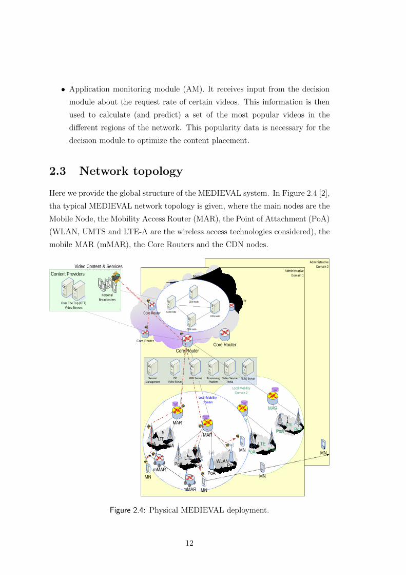
Here we provide the global structure of the MEDIEVAL system. In Figure 2.4 [2],
tha typical MEDIEVAL network topology is given, where the main nodes are the
Mobile Node, the Mobility Access Router (MAR), the Point of Attachment (PoA)
(WLAN, UMTS and LTE-A are the wireless access technologies considered), the
mobile MAR (mMAR), the Core Routers and the CDN nodes.
Administrative Domain 2
Administrative Domain 1
PoA
PoA
PoA
PoA LTE
MAR
LTEWLANPoA
MAR
PoA
PoAPoA
PoAPoA
Local Mobility Domain 2
CDN
CDN
PoA
PoA
PoA
PoALTE
MAR
LTE WLANPoA
MAR
PoA
PoA PoA
PoA PoA
Local Mobility Domain
MN
MN
Internet
Video Content & ServicesContent Providers
CDN
CDN
mMAR
mMAR
Over The Top (OTT) Video Servers
Personal Broadcasters
Network Transport
Core Router
Core Router
CDN node
CDN node
CDN node
CDN node
ISP Video Server
ALTO ServerMIIS ServerSessionManagement
ProvisioningPlatform
Video Service Portal
MN
Core Router
Core Router
Core Router
MN
MN
PBS (multicast traffic)
Figure 2.4: Physical MEDIEVAL deployment.
12
Chapter 3
MCDN description
A MCDN is a network of servers that cooperate transparently to optimize the
delivery of content to end users on any type of access network. As for traditional
CDNs, the primary purpose of a MCDN is to serve content to end users with high
availability and high performance. In addition, MCDNs can be used to optimize
content delivery for the unique characteristics of wireless networks and mobile
devices, such as limited network capacity, or lower device resolution. Content
adaptation can help address challenges inherent to mobile networks which have
high latency, higher packet loss and huge variation in download capacity.
In the MEDIEVAL project the CDN component provides a MCDN solution for
video delivery including network based caching, network guided optimisation of
content delivery and advanced multicast solutions. This includes maintaining an
efficient and stable overlay topology for the control and management of the CDN
nodes, performing load-balancing among the video sources and network elements,
selecting optimal content locations as well as relaying connections for mobility,
caching, or confidentially reasons. This requires a continuous monitoring of the
current conditions of the entire system, in particular the status and distribution
of the CDN nodes, as well as the popularity of content. Using the collected data
it dynamically maintains an optimal configuration of a set of servers for content
distribution and select optimal sources for transmitting the video to the user.
As shown in Figure 3.1, taken from [8], the CDN component consists of three
modules. The application monitoring module (AM) keeps track of the popular-
ity of content and provides this information to the decision module (DM). The
decision module is responsible for content and user related decisions, e.g., opti-
13
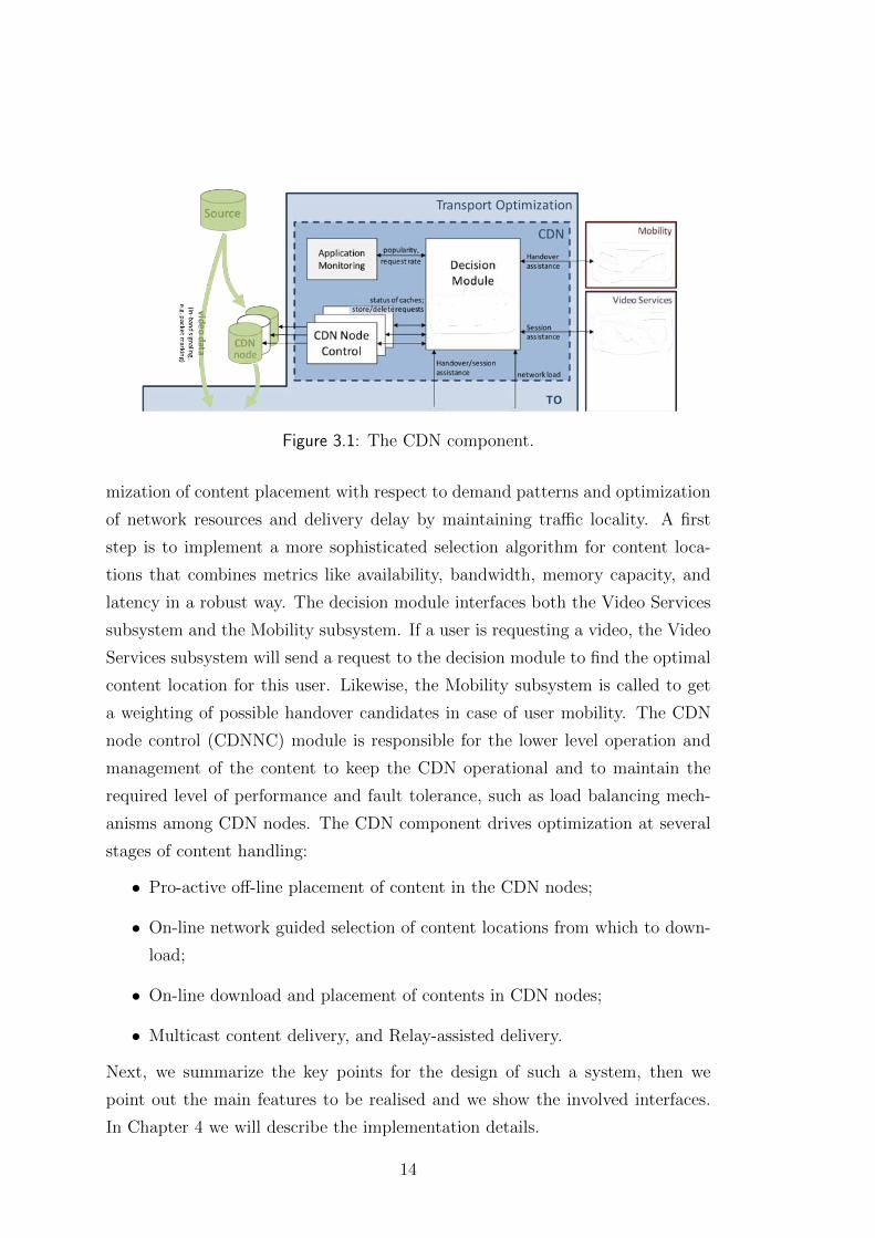
Figure 3.1: The CDN component.
mization of content placement with respect to demand patterns and optimization
of network resources and delivery delay by maintaining traffic locality. A first
step is to implement a more sophisticated selection algorithm for content loca-
tions that combines metrics like availability, bandwidth, memory capacity, and
latency in a robust way. The decision module interfaces both the Video Services
subsystem and the Mobility subsystem. If a user is requesting a video, the Video
Services subsystem will send a request to the decision module to find the optimal
content location for this user. Likewise, the Mobility subsystem is called to get
a weighting of possible handover candidates in case of user mobility. The CDN
node control (CDNNC) module is responsible for the lower level operation and
management of the content to keep the CDN operational and to maintain the
required level of performance and fault tolerance, such as load balancing mech-
anisms among CDN nodes. The CDN component drives optimization at several
stages of content handling:
• Pro-active off-line placement of content in the CDN nodes;
• On-line network guided selection of content locations from which to down-
load;
• On-line download and placement of contents in CDN nodes;
• Multicast content delivery, and Relay-assisted delivery.
Next, we summarize the key points for the design of such a system, then we
point out the main features to be realised and we show the involved interfaces.
In Chapter 4 we will describe the implementation details.
14
3.1 Design
We implement a customized software following the specifications required by the
MEDIEVAL system. Since mobile core networks are usually hierarchical, i.e.,
with a central core part as well as branches and leaves in different regions of a
deployment area, for example a country, the MCDN software has a hierarchi-
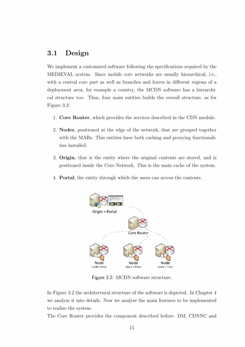
cal structure too. Thus, four main entities builds the overall structure, as for
Figure 3.2:
1. Core Router, which provides the services described in the CDN module.
2. Nodes, positioned at the edge of the network, that are grouped together
with the MARs. This entities have both caching and proxying functionali-
ties installed.
3. Origin, that is the entity where the original contents are stored, and is
positioned inside the Core Network. This is the main cache of the system.
4. Portal, the entity through which the users can access the contents.
Figure 3.2: MCDN software structure.
In Figure 3.2 the architectural structure of the software is depicted. In Chapter 4
we analyse it into details. Now we analyse the main features to be implemented
to realize the system.
The Core Router provides the component described before: DM, CDNNC and
15
AM. It is an entity that can manage a database of information about the popu-
larity of the contents and can manage them (i.e., making decisions on the storage
locality) using a database containing network status characteristics. These are
theoretically made available by the ALTO (Application-Layer Traffic Optimisa-
tion) [28] module, but in our work we did not use it. Moreover, the Core Router
can be called from the other entities in case they are not able to take decisions
(i.e., request routing1). The important aspect of this entity is that it is not fully
responsible of the request routing, since this feature is associated to the Nodes.
Another aspect to underline is the ability of wrap up together popularity infor-
mation obtained by the Nodes. This means, given local popularity information,
the AM module is able to store them in one main database and use it to make
decisions on delivering, deleting and maintaining contents in the different Nodes.
These actions are taken off-line and the entire system can continuously work
without interruptions.
The Core Router works as follows:
• It checks for local database information provided by the Nodes;
• It inserts them in the main database and handles the popularity values
stored into it (AM);
• Using these information, makes decisions about the managing of the Nodes’
caches (DM);
• In case of actions to be taken, it informs the CDNNC to perform them.
The Nodes are the combination of three functionalities: the local request routing,
the caching of the contents and the managing of information about local popular-
ity. The purpose of the first functionality is to understand if the request can be
performed directly from the local cache, which means that the request does not
travel through the Core Network. To find a solution to the problem of data flows
in the Core Network is one of the main objectives of our work. Moreover, if the
request routing can not be done by Nodes (i.e., the content is not stored locally),
they must contact DM to obtain the routing information. Obviously, the second
1Request routing: each individual request is routed in an optimized way, based on the
network topology, network load, service availability, per-server content availability and in-use
CDN policy.
16
functionality is strictly linked to the first one, since we store data inside the local
caches and to do that we get informed by the DM (through the CDNNC module)
about the data to be stored. The last functionality concerns the collection of
popularity values. Due to the nature of a MCDN it is clear that the popularity is
obtained at the edge of the network. This is simply the number of requests, for
a certain content, that travel through a Node in a given time interval (that can
be set taking into account the scalability issues). This information is stored in
the local database, that is uploaded into the Core Router. Thus, a Node works
as follows:
• It intercepts the requests sent by the users and performs the request routing
(using local information or contacting the DM);
• It updates the local popularity database with the number of requests and
sends it to the Core Router;
• It listens to the commands sent by CDNNC about managing the cache.
The Origin, as said before, is the main cache, located inside the Core Network,
where the original contents are stored. This entity gives access to the users to the
stored contents and provides to the Nodes the possibility to get the contents to
be stored in the local caches. The location of the Origin impacts the performance
of the overall system, and, should be located at an equal distance from all the
caches.
The Portal is a simple web page with video playing feature where the stored
contents in the Origin are shown and where the users can connect to retrieve
them. Moreover, through the Portal, we can simulate the popularity behaviour
of the videos and we also set the network parameters (provided by ALTO) to test
some critical network configuration. The structure of Portal is as follows:
• The Portal shows an Homepage where we can access the contents;
• Selecting one of the content we start playing it and some more details about
it are shown;
• We can navigate through the website to reach the Popularity Simulation
page and the Network Configuration page.
17
3.2 Features
The main features implemented are described here, while in Chapter 4 we analyse
them to understand how they are realized.
The first key aspect concerns the request routing. We move this functionality to
the edge of the network. In fact, most of CDN systems are based on a centralized
request routing, that means, a client, after a request, is redirected to the correct
cache and this action is taken by a centralized entity. Thus, the problem is that
the signalling inside the Core Network increases while the scope of our work is to
reduce it to the minimum.
Another feature we introduce is the popularity-based caching. Since the system is
mobile, a new concept of popularity is foreseen. The caching is based on values
of popularity, thus, a specific algorithm based on these would be beneficial for
the system. However this is out of purpose of this thesis. Moreover, we study
also how the caching has to be done, in terms of technologies involved.
One important feature we provide is the robustness of the CDN component, which
means, in case of failures (e.g., Node fails or loses packets), the subsystem must
be able to react without introducing extra delay and without letting users know
about it. This aspect is very important since the users can be involved in some
failures, it is unavoidable, and following the QoE guidelines, they should continue
to use the service without knowing absolutely what has happened.
The last aspect to take into account is the ability of maintaining the session
continuity during mobility. In fact the CDN module works also when a user moves
from a PoA to another PoA. Thus, we pay attention to the sessions opened during
the streaming and manage them during the handovers among different Nodes.
3.3 Interfaces
The CDN architecture features several interfaces among its own modules and
external subsystems. A detailed description and specification of all internal in-
terfaces can be found in D5.2 [5] and D5.3 [7]. Next, we analyse the interfaces
included in our work.
• The DM CDNNC If is used by the DM to request and manage informa-
tion related to Nodes from the CDNNC module. Through this interface, the
18
DM initiates Nodes management operations, such as updating the content
stored in the CDN Nodes. It also enables the DM to get information on a
set of CDN Nodes, such as their current content or operational state;
• The CDNNC CDNnode If is used for low level CDN functionalities re-
lated to the control and management of the Nodes. This includes content
update requests, i.e., install and remove content from CDN nodes, status
information updates, as well as maintenance requests, e.g., to power down
nodes;
• The DM AM If is used by the DM to periodically request content popu-
larity information monitored by the AM. The response provides a list of the
‘Top 10’ most popular content in a certain region to the DM. Upon receipt
of the response message, the DM triggers the CDN algorithm to determine
whether the cached content in one of the Nodes should be updated. This
interface is also used to update the popularity database at the AM with
aggregated content popularity information gathered by the request routing.
19

20
Chapter 4
MCDN implementation
In this chapter we describe how the system is implemented, with focus on which
technologies are used and how. Then, we analyse how the entities of the system
described in the previous chapter work and what are the details and interesting
solutions that we have developed. Hence, we map the interfaces to the imple-
mented software modules. Finally, we describe a practical scenario implemented
in a real testbed in order to collect the results shown in Chapter 5.
4.1 Requirements
The entire system is IPv6-based since it gives us the possibility to use the DMM
[3], implemented to manage the handovers among different access technologies
and network regions. IPv6 well supports the mobility but it does not implement
the transparency to the end-user, since Network Address Translation (NAT) is
not implemented. Next, we describe how to address this issue with the tproxy
module [9, 10].
We focus on a streaming solution based on the HTTP protocol and indepen-
dent of media transport protocols such as Real Time Streaming Protocol (RTSP)
or Real Time Protocol (RTP). Thus, we can transport over HTTP any kind of
file, and the key aspect of this protocol is that it works well using proxies and
masquerading features. Furthermore, we use MPEG-DASH (Dynamic Adaptive
Streaming over HTTP) [11, 12, 13] as video streaming protocol. It is an adap-
tive bitrate streaming technology where a multimedia file is partitioned into one
or more segments and delivered to a client using HTTP. A media presentation
21
description (MPD) describes segment information (timing, URL, media charac-
teristics such as video resolution and bit rates). Segments can contain any media
data, however the specification provides guidance and formats with two types of
containers: MPEG-4 file format and MPEG-2 Transport Stream. One or more
representations (i.e., versions at different resolutions or bit rates) of multimedia
files are available, and the selection can be made based on the current network
conditions, device capabilities and user preferences. DASH is agnostic of the un-
derlying application layer protocol [14, 15, 16].
Using HTTP we can also adopt a simple Proxy Web Server for the proxy func-
tionalities and simple Web Server for caching.
In particular, in our work we use Squid as proxy server [17, 18] and Apache
as web server [19]. Squid in an open-source proxy server able also to do web
caching. It has a wide variety of uses, from speeding up a web server by caching
repeated requests, to caching web, DNS and other computer network lookups for
a group of people sharing network resources and to aiding security by filtering
traffic. Although primarily used for HTTP and FTP, Squid proxy server includes
limited support for several other protocols including TLS, SSL, Internet Gopher
and HTTPS.
The Apache HTTP server, commonly referred to as Apache, is a web server soft-
ware program notable for playing a key role in the initial growth of the World
Wide Web. Apache supports a variety of features implemented as compiled mod-
ules which extend the core functionality. These can range from server-side pro-
gramming language support to authentication schemes. Some common language
interfaces support Perl, Python and PHP.
Our framework is mainly written in Perl [20], that is an high-level, general-
purpose, interpreted and dynamic programming language. It is well supported
by Apache web server and Squid proxy server.
Moreover, our project is developed using the operating system Unix (in particular
Linux Ubuntu v10.04) and using IPv6.
As last key point, we say that the subsystem in built based on the distribution
of databases containing information about the popularity and also information
about the network status. We point out that, as proof of concept, simple text-
based databases are considered and next their structure and distribution are
shown.
22
We implement local (in the Nodes), main (in the Core Router) and network
information (in all the machines) databases in our framework.
4.2 Entities
We now analyse the details of each entity deployed in our system. We present, for
everyone, the software structure with a short description of the specific blocks.
Moreover, we say if Apache web server or Squid proxy server are involved in it,
and in case we give a short setting specification of them.
Inside each machine we set a configuration file (.pm in Perl), through which we
let the entities gather information such as IP addresses (to be communicated)
and paths of databases (to let scripts reach them). There are also some tuning
parameters, such as time interval between uploads (for databases in the Nodes)
and time interval between maintenance actions (for the main database in the
Core Router).
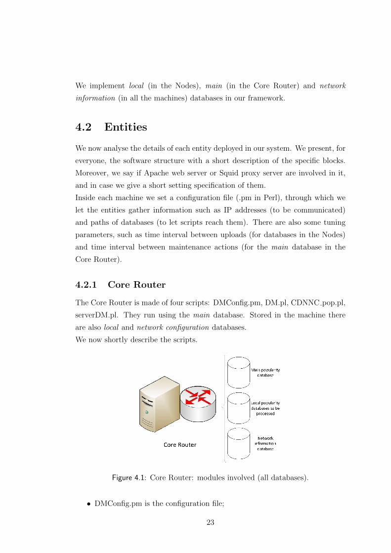
4.2.1 Core Router
The Core Router is made of four scripts: DMConfig.pm, DM.pl, CDNNC pop.pl,
serverDM.pl. They run using the main database. Stored in the machine there
are also local and network configuration databases.
We now shortly describe the scripts.
Figure 4.1: Core Router: modules involved (all databases).
• DMConfig.pm is the configuration file;
23
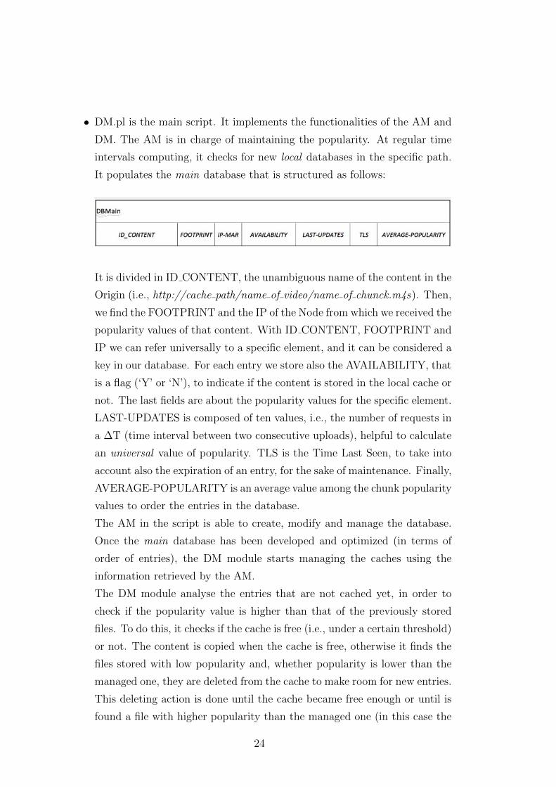
• DM.pl is the main script. It implements the functionalities of the AM and
DM. The AM is in charge of maintaining the popularity. At regular time
intervals computing, it checks for new local databases in the specific path.
It populates the main database that is structured as follows:
It is divided in ID CONTENT, the unambiguous name of the content in the
Origin (i.e., http://cache path/name of video/name of chunck.m4s). Then,
we find the FOOTPRINT and the IP of the Node from which we received the
popularity values of that content. With ID CONTENT, FOOTPRINT and
IP we can refer universally to a specific element, and it can be considered a
key in our database. For each entry we store also the AVAILABILITY, that
is a flag (‘Y’ or ‘N’), to indicate if the content is stored in the local cache or
not. The last fields are about the popularity values for the specific element.
LAST-UPDATES is composed of ten values, i.e., the number of requests in
a ∆T (time interval between two consecutive uploads), helpful to calculate
an universal value of popularity. TLS is the Time Last Seen, to take into
account also the expiration of an entry, for the sake of maintenance. Finally,
AVERAGE-POPULARITY is an average value among the chunk popularity
values to order the entries in the database.
The AM in the script is able to create, modify and manage the database.
Once the main database has been developed and optimized (in terms of
order of entries), the DM module starts managing the caches using the
information retrieved by the AM.
The DM module analyse the entries that are not cached yet, in order to
check if the popularity value is higher than that of the previously stored
files. To do this, it checks if the cache is free (i.e., under a certain threshold)
or not. The content is copied when the cache is free, otherwise it finds the
files stored with low popularity and, whether popularity is lower than the
managed one, they are deleted from the cache to make room for new entries.
This deleting action is done until the cache became free enough or until is
found a file with higher popularity than the managed one (in this case the
24
process is stopped, waiting for an increasing on popularity value).
The process restart from the beginning of the procedure following always
an AM-DM interaction;
• CDNNC pop.pl is responsible for carrying out the actions of the DM mod-
ule. It checks for active Nodes, checks for free space in the Nodes and sends
the action messages (i.e., copy or delete of files) to them if necessary. These
messages are sent to the server process running in background in the Nodes;
• serverDM.pl is a script that runs in background, through which the Nodes
can contact the Core Router if they can not manage some user’s requests.
As said before, the system tries to manage the requests locally, i.e., when
the requested content is stored in the caches, but in case the content is
not available, the Core Router looks for information about the availability
of files in the system. Then it recalls both the main database and the
network information database. If a content is stored in a cache closer than
the Origin (in terms of number of hops) to the Node asking for it and
in case that specific cache is not overloaded (in terms of number of users
that are served by it), the Core Router replies to the Nodes with the best
location, otherwise, if the conditions are not satisfied, it replies simply with
the Origin location. During the description of the Node entity, we analyse
more specifically how these messages are handled by the system.
4.2.2 Node
The Node is installed at the edge of the system. It computes the popularity values
using the user requests and maintains a cache to store the contents. Moreover,
it is transparent to the end-user and it intercepts and manages all the requests
passing through it. Then, we can identify two distinct roles of the Node: 1)
manager of CDN, 2) builder of a system of sophisticated networking rules to
create a proxy service that takes into account the mobility issues and leverages
the communication with the DMM system for the management of handovers.
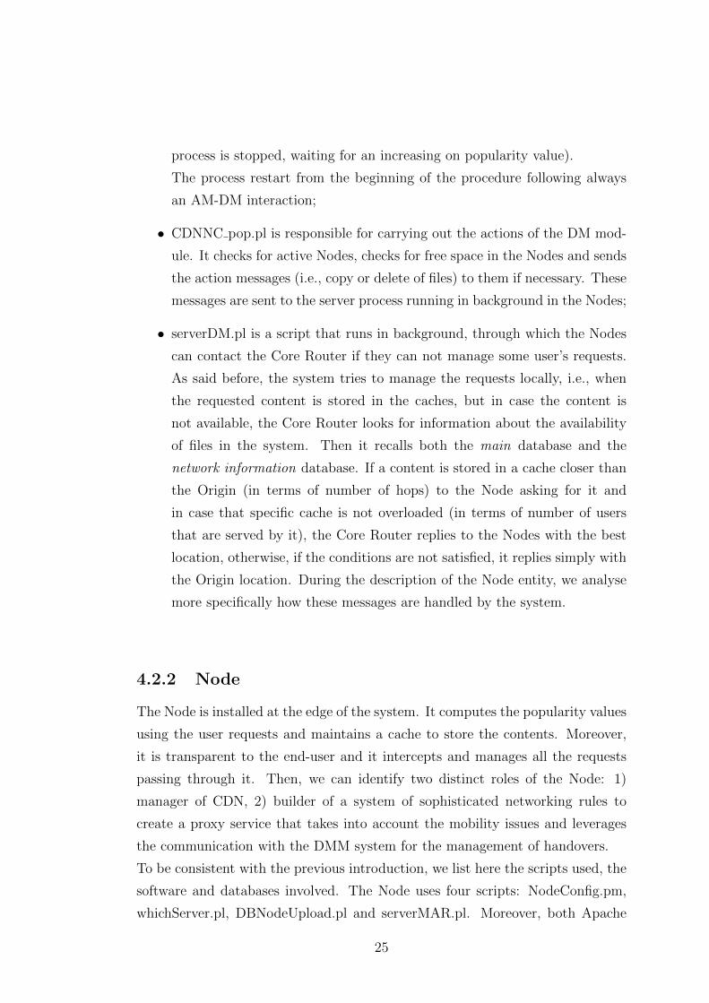
To be consistent with the previous introduction, we list here the scripts used, the
software and databases involved. The Node uses four scripts: NodeConfig.pm,
whichServer.pl, DBNodeUpload.pl and serverMAR.pl. Moreover, both Apache
25
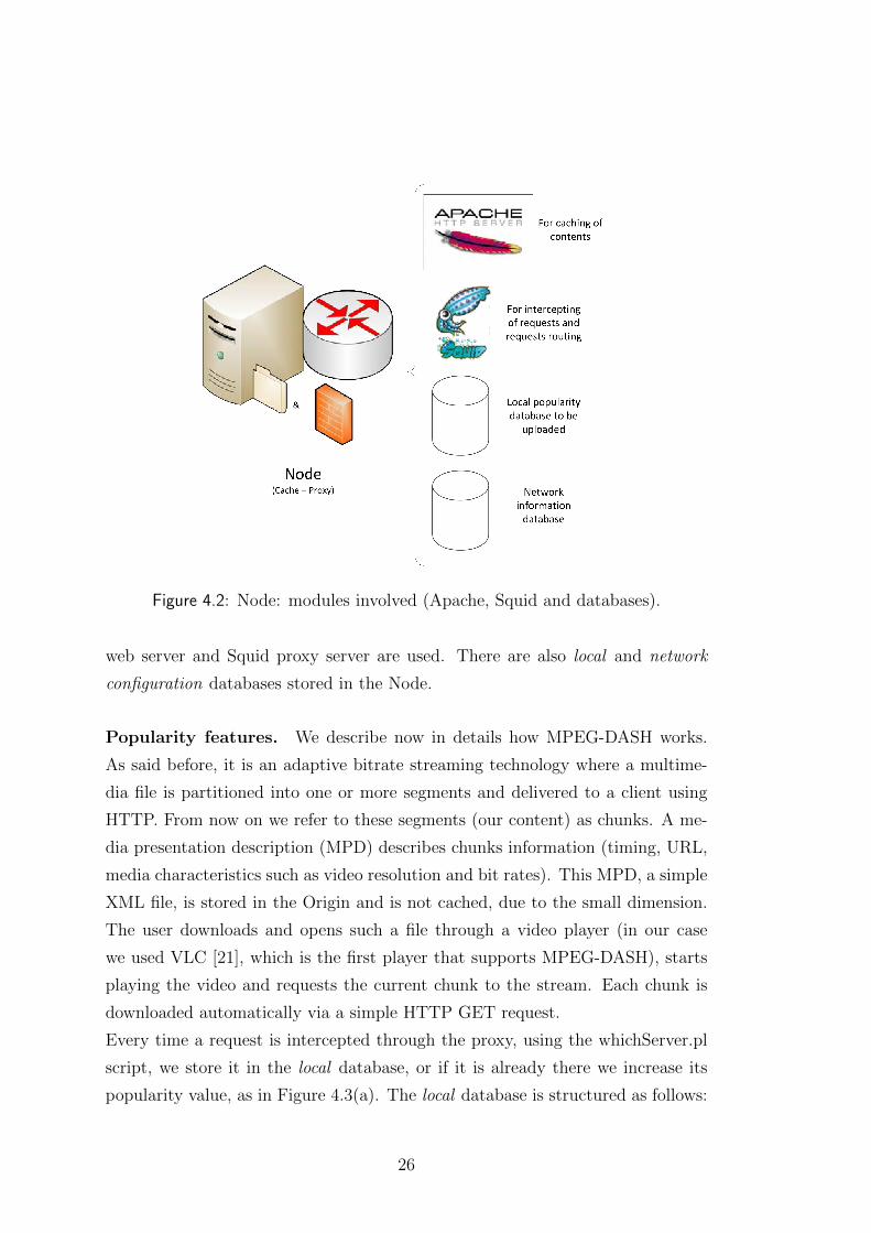
Figure 4.2: Node: modules involved (Apache, Squid and databases).
web server and Squid proxy server are used. There are also local and network
configuration databases stored in the Node.
Popularity features. We describe now in details how MPEG-DASH works.
As said before, it is an adaptive bitrate streaming technology where a multime-
dia file is partitioned into one or more segments and delivered to a client using
HTTP. From now on we refer to these segments (our content) as chunks. A me-
dia presentation description (MPD) describes chunks information (timing, URL,
media characteristics such as video resolution and bit rates). This MPD, a simple
XML file, is stored in the Origin and is not cached, due to the small dimension.
The user downloads and opens such a file through a video player (in our case
we used VLC [21], which is the first player that supports MPEG-DASH), starts
playing the video and requests the current chunk to the stream. Each chunk is
downloaded automatically via a simple HTTP GET request.
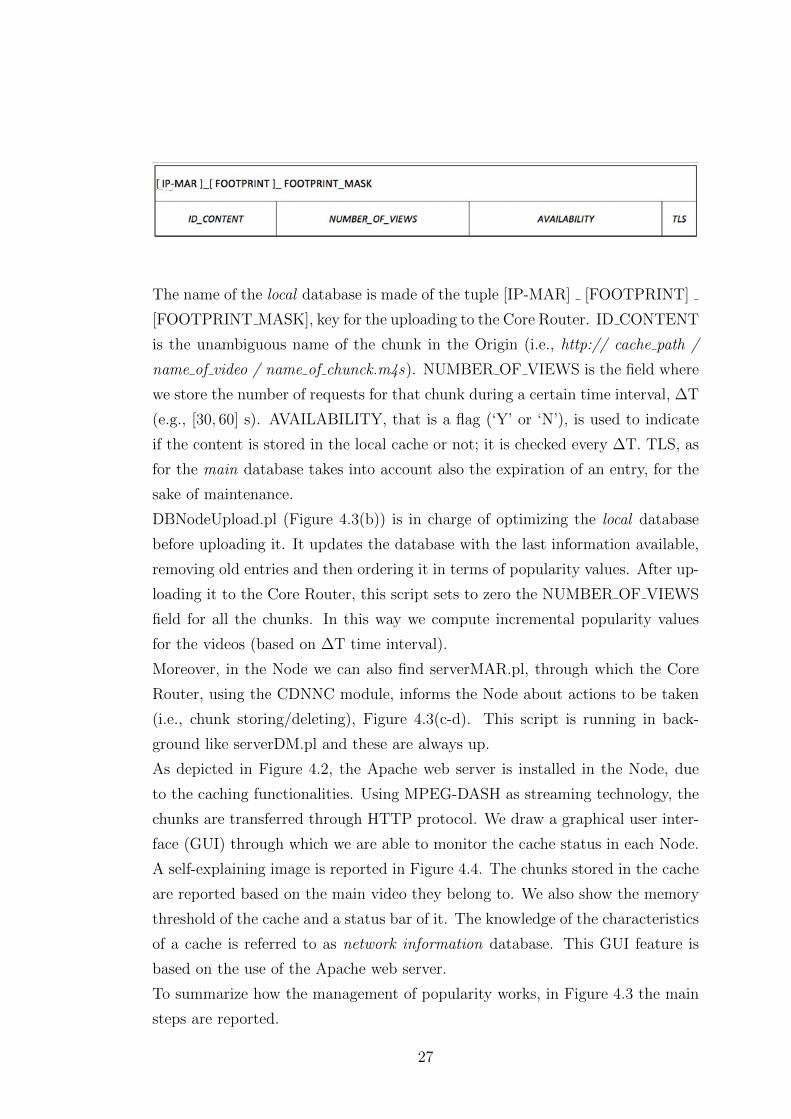
Every time a request is intercepted through the proxy, using the whichServer.pl
script, we store it in the local database, or if it is already there we increase its
popularity value, as in Figure 4.3(a). The local database is structured as follows:
26
The name of the local database is made of the tuple [IP-MAR] [FOOTPRINT]
[FOOTPRINT MASK], key for the uploading to the Core Router. ID CONTENT
is the unambiguous name of the chunk in the Origin (i.e., http:// cache path /
name of video / name of chunck.m4s). NUMBER OF VIEWS is the field where
we store the number of requests for that chunk during a certain time interval, ∆T
(e.g., [30, 60] s). AVAILABILITY, that is a flag (‘Y’ or ‘N’), is used to indicate
if the content is stored in the local cache or not; it is checked every ∆T. TLS, as
for the main database takes into account also the expiration of an entry, for the
sake of maintenance.
DBNodeUpload.pl (Figure 4.3(b)) is in charge of optimizing the local database
before uploading it. It updates the database with the last information available,
removing old entries and then ordering it in terms of popularity values. After up-
loading it to the Core Router, this script sets to zero the NUMBER OF VIEWS
field for all the chunks. In this way we compute incremental popularity values
for the videos (based on ∆T time interval).
Moreover, in the Node we can also find serverMAR.pl, through which the Core
Router, using the CDNNC module, informs the Node about actions to be taken
(i.e., chunk storing/deleting), Figure 4.3(c-d). This script is running in back-
ground like serverDM.pl and these are always up.
As depicted in Figure 4.2, the Apache web server is installed in the Node, due
to the caching functionalities. Using MPEG-DASH as streaming technology, the
chunks are transferred through HTTP protocol. We draw a graphical user inter-
face (GUI) through which we are able to monitor the cache status in each Node.
A self-explaining image is reported in Figure 4.4. The chunks stored in the cache
are reported based on the main video they belong to. We also show the memory
threshold of the cache and a status bar of it. The knowledge of the characteristics
of a cache is referred to as network information database. This GUI feature is
based on the use of the Apache web server.
To summarize how the management of popularity works, in Figure 4.3 the main
steps are reported.
27
Figure 4.3: Popularity values management.
28
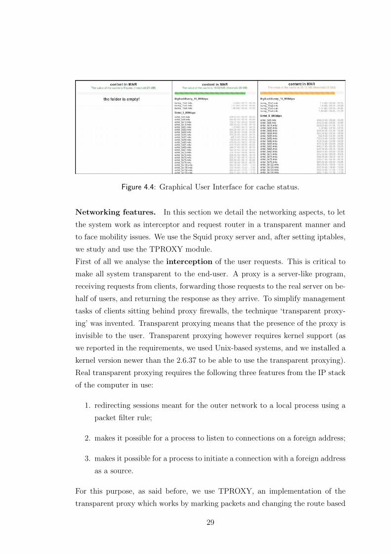
Figure 4.4: Graphical User Interface for cache status.
Networking features. In this section we detail the networking aspects, to let
the system work as interceptor and request router in a transparent manner and
to face mobility issues. We use the Squid proxy server and, after setting iptables,
we study and use the TPROXY module.
First of all we analyse the interception of the user requests. This is critical to
make all system transparent to the end-user. A proxy is a server-like program,
receiving requests from clients, forwarding those requests to the real server on be-
half of users, and returning the response as they arrive. To simplify management
tasks of clients sitting behind proxy firewalls, the technique ‘transparent proxy-
ing’ was invented. Transparent proxying means that the presence of the proxy is
invisible to the user. Transparent proxying however requires kernel support (as
we reported in the requirements, we used Unix-based systems, and we installed a
kernel version newer than the 2.6.37 to be able to use the transparent proxying).
Real transparent proxying requires the following three features from the IP stack
of the computer in use:
1. redirecting sessions meant for the outer network to a local process using a
packet filter rule;
2. makes it possible for a process to listen to connections on a foreign address;
3. makes it possible for a process to initiate a connection with a foreign address
as a source.
For this purpose, as said before, we use TPROXY, an implementation of the
transparent proxy which works by marking packets and changing the route based
29
on the packet marking. The foreign address bind and TPROXY redirection is
enabled via a new socket option, IP TRANSPARENT. Without it neither the
bind nor the TPROXY target works. To work in a transparent way to the used
connections (simple HTTP connection in our case) are redirected via iptables. In
an IPv4 environment this is already supported and it is equivalent to the following
NAT rule:
iptables -t nat -A PREROUTING -j DNAT --to-dest <localip >
--to-port <proxyport >
where < localip > is the IP address of the interface where the packet entered the
IP stack and < proxyport > is the port where the proxy was bound to.
To do this in an IPv6 environment, where NAT is not implemented, we created
this rule
ip6tables -t mangle -A PREROUTING -s $PREF -p tcp --dport
80 -j TPROXY --tproxy -mark 0x1/0x1 --on -port 3129
where we manage, in the PREROUTING chain, the connections whit a certain
source ($PREF that is the set of ip addresses served by the Node) of protocol
TCP at port 80, marking them to be recognised by the TPROXY. In the end
we send them to the port of Squid proxy server, enabled to work with TPROXY
(in our case 3129, and it is declared also in the configuration of the Squid proxy
server as http port 3129 tproxy).
Then the marked sockets are routed locally and to do this we configure these
rules:
ip -f inet6 rule add fwmark 1 lookup 100 prio 500
ip -f inet6 route add local default dev $WLAN table 100
These rules have an high priority compared to the DMM rules, to let the system
work with it.
To listen to connections on a foreign address, as the presence of the proxy is
transparent to the client, we add a TPROXY rule automatically (e.g., to redirect
a connection meant for a given server on a port to a local process). To do
this, it is enough to call bind() on a socket with a foreign IP address, and if a
30
new connection to the given foreign IP address is routed through the proxy, the
connection is intercepted. The behaviour is the following:
• the proxy sets the IP TRANSPARENT socket option on the listening socket;
• the proxy then binds to the foreign address;
• the proxy accepts incoming connections.
It requires additional ip6tables rules with the socket module of the tproxy patches:
ip6tables -t mangle -N DIVERT
ip6tables -t mangle -A DIVERT -j MARK --set -mark 1
ip6tables -t mangle -A DIVERT -j ACCEPT
ip6tables -t mangle -A PREROUTING -p tcp -m socket -j
DIVERT
The overall setting of the iptables works with TPROXY module in interception
mode and it is summarized here below (the order of rules is important since it
defines the priorities in the chain).
Interception rules
ip -f inet6 rule add fwmark 1 lookup 100 prio 500
ip -f inet6 route add local default dev $WLAN table 100
ip6tables -t mangle -N DIVERT
ip6tables -t mangle -A DIVERT -j MARK --set -mark 1
ip6tables -t mangle -A DIVERT -j ACCEPT
ip6tables -t mangle -A PREROUTING -p tcp -m socket -j
DIVERT
ip6tables -t mangle -A PREROUTING -s $PREF -p tcp --dport
80 -j TPROXY --tproxy -mark 0x1/0x1 --on -port 3129
Now we describe the request routing of the user requests using Squid proxy
server. We know that all the requests from users, passing through the Node, are
intercepted and passed to Squid proxy server. It analyses them and decides if a
request can be served directly by the local cache, the Origin or other caches. To
do this, Squid proxy server recall a function, the whichServer.pl script, which is
an ‘helper’, i.e., it is able to elaborate the requests.
31
Two possible solutions for the problem of the request routing are the use of a
redirector or a re-writer.
• Redirection is a defined feature of HTTP where a status code between 300
and 399 is sent to the requesting client along with an alternative URL. A
redirector helper in Squid proxy server uses this feature of HTTP to re-
direct the client browsers to alternative URLs. We may be familiar with
302 responses to POST requests or between domains;
• A re-writer does not use this feature of HTTP, but merely mangles the URL
into a new form. HTTP defines many features which this breaks. This can
cause problems at both the client and server and for this should be avoided
in favour of true redirection whenever possible. Moreover, this causes many
problems with the TPROXY module, due to local-loops arising from the
use of the packets marking, which, when they are rewritten from Squid
proxy server, lose the reference in the chain of the internal connection of
the system.
To overcome the issues of these two solutions, where the first one introduces
a lot of useless signalling and the second one does not work with TPROXY
and introduces mobility problems, we select HTTP routing. In the Squid proxy
server we write a reachability setting of the caches, based on their tagging. In
the configuration file of the software (set for each Node), we create the tags, as
reported here:
# check if helper sent "OK tag=CACHE_ID" and pass it to
server CACHE_IP_ADDR
acl cacheOkay tag CACHE_ID
cache_peer CACHE_IP_ADDR parent 80 0 no-tproxy name=
ApacheCACHE_ID
cache_peer_access ApacheCACHE_ID allow cacheOkay
cache deny all
This sequence is written for each involved cache, and with this solution every
Squid proxy server installed in the Nodes can manage the requests in this way.
Through these instructions we impose rules of access to the caches, reachable
with a reference, e.g., the IP address. Then the helper whichServer.pl takes a
32
request, it replies to the Squid proxy server with a tag, to know how to reach
the chunks stored in a cache. As said before, this procedure avoids redirection
messages because it handles the connections to the caches, without informing
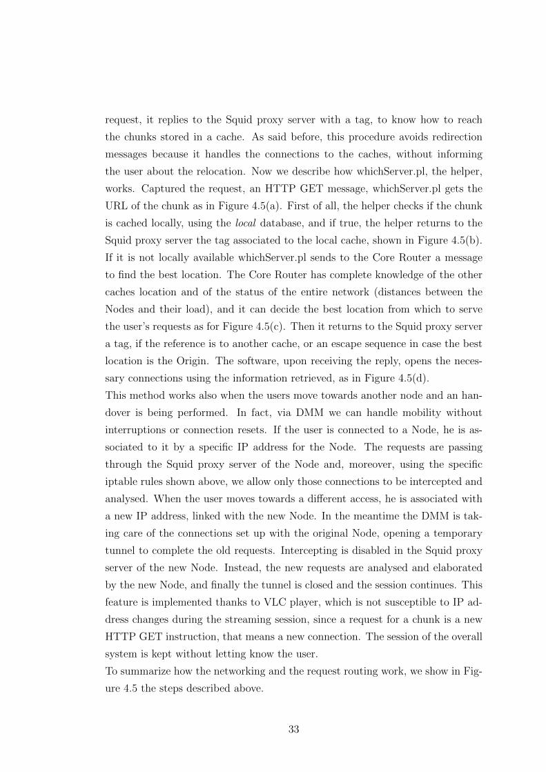
the user about the relocation. Now we describe how whichServer.pl, the helper,
works. Captured the request, an HTTP GET message, whichServer.pl gets the
URL of the chunk as in Figure 4.5(a). First of all, the helper checks if the chunk
is cached locally, using the local database, and if true, the helper returns to the
Squid proxy server the tag associated to the local cache, shown in Figure 4.5(b).
If it is not locally available whichServer.pl sends to the Core Router a message
to find the best location. The Core Router has complete knowledge of the other
caches location and of the status of the entire network (distances between the
Nodes and their load), and it can decide the best location from which to serve
the user’s requests as for Figure 4.5(c). Then it returns to the Squid proxy server
a tag, if the reference is to another cache, or an escape sequence in case the best
location is the Origin. The software, upon receiving the reply, opens the neces-
sary connections using the information retrieved, as in Figure 4.5(d).
This method works also when the users move towards another node and an han-
dover is being performed. In fact, via DMM we can handle mobility without
interruptions or connection resets. If the user is connected to a Node, he is as-
sociated to it by a specific IP address for the Node. The requests are passing
through the Squid proxy server of the Node and, moreover, using the specific
iptable rules shown above, we allow only those connections to be intercepted and
analysed. When the user moves towards a different access, he is associated with
a new IP address, linked with the new Node. In the meantime the DMM is tak-
ing care of the connections set up with the original Node, opening a temporary
tunnel to complete the old requests. Intercepting is disabled in the Squid proxy
server of the new Node. Instead, the new requests are analysed and elaborated
by the new Node, and finally the tunnel is closed and the session continues. This
feature is implemented thanks to VLC player, which is not susceptible to IP ad-
dress changes during the streaming session, since a request for a chunk is a new
HTTP GET instruction, that means a new connection. The session of the overall
system is kept without letting know the user.
To summarize how the networking and the request routing work, we show in Fig-
ure 4.5 the steps described above.
33
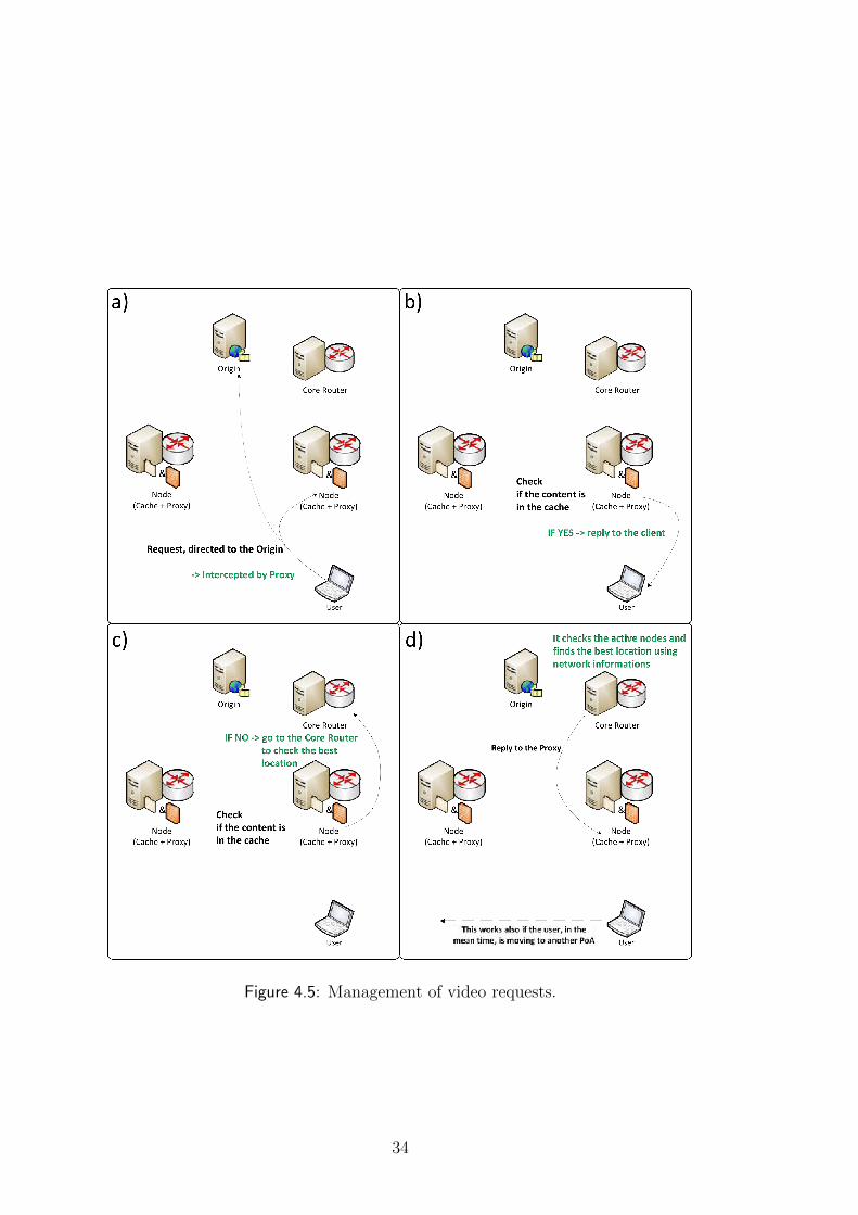
Figure 4.5: Management of video requests.
34
4.2.3 Origin
The Origin is implemented together with the Portal in the same machine. This
implementation choice is only for content managing and Portal displaying con-
venience. Here we describe only the functionalities of the Origin and in the next
section those of the Portal, keeping in mind that these are working together.
Figure 4.6: Origin: entities involved (Apache and database).
The Apache web server is installed in the Origin, that represents the central
cache. We have no scripts or databases involved since all features of the Origin
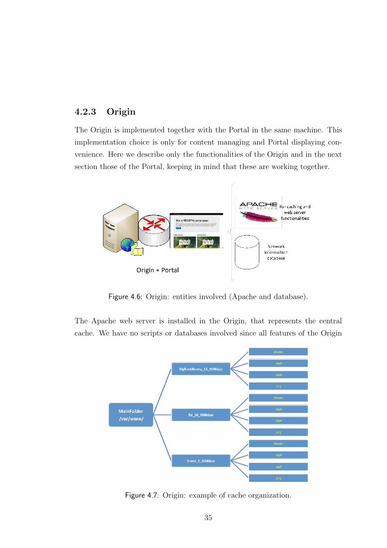
Figure 4.7: Origin: example of cache organization.
35
are provided by Apache web server. One important aspect is that in the main
cache, the Origin, all the files are stored, not only the popular chunks. More-
over, not only the chunks are cached, but also the MPD (Media Presentation
Description) and the MP4 control file for each content. Further more, the main
cache is structured as for Figure 4.7. As depicted here, all the files are stored in
the Apache web server folder (i.e., /var/www/). The names of the main folders
(BigBuckBunny 15 900kbps, Ed 10 500kbps, Sintel 5 800kbps) are used to dis-
tinguish the different contents. In this way we can insert, without ambiguity, the
links to the contents in the MPD files.
For the sake of clarity, we report here a section of an MPD file:
<?xml version="1.0" encoding="UTF-8"?>
<MPD xmlns:xsi="http://www.w3.org/2001/XMLSchema"
xmlns="urn:mpeg:mpegB:schema:DASH:MPD:DIS2011"
xsi:schemaLocation="urn:mpeg:mpegB:schema:DASH:MPD:DIS2011"
profiles= "urn:mpeg:mpegB:profile:dash:isoff-basic-on-demand:cm"
type="OnDemand"
mediaPresentationDuration="PT0H8M10.02S"
minBufferTime="PT1.5S">
<name>Big Buck Bunny</name>
<subname>5 sec</subname>
<description>Big Buck Bunny plot.</description>
<image>http://Origin/BigBuckBunny_5_900kbps/bunny_5_900kbps_dash.png</image>
<width>960</width>
<height>720</height>
<segment>PT5.00S</segment>
<Period>
<Group segmentAlignmentFlag="true" mimeType="video/mp4">
<Representation mimeType="video/mp4" width="960" height="720" startWithRAP="true" bandwidth="907879">
<SegmentInfo duration="PT5.00S">
<InitialisationSegmentURL sourceURL="http://Origin/BigBuckBunny_5_900kbps/bunny_5_900kbps_dash.mp4"/>
<Url sourceURL="http://Origin/BigBuckBunny_5_900kbps/bunny_5s1.m4s"/>
<Url sourceURL="http://Origin/BigBuckBunny_5_900kbps/bunny_5s2.m4s"/>
...
All the links refer to the Origin caches (see ‘http://Origin/’), thus, the requests
sent by the users are always referring to it.
36
4.2.4 Portal
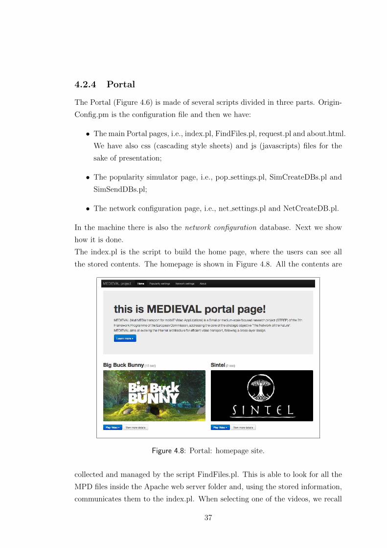
The Portal (Figure 4.6) is made of several scripts divided in three parts. Origin-
Config.pm is the configuration file and then we have:
• The main Portal pages, i.e., index.pl, FindFiles.pl, request.pl and about.html.
We have also css (cascading style sheets) and js (javascripts) files for the
sake of presentation;
• The popularity simulator page, i.e., pop settings.pl, SimCreateDBs.pl and
SimSendDBs.pl;
• The network configuration page, i.e., net settings.pl and NetCreateDB.pl.
In the machine there is also the network configuration database. Next we show
how it is done.
The index.pl is the script to build the home page, where the users can see all
the stored contents. The homepage is shown in Figure 4.8. All the contents are
Figure 4.8: Portal: homepage site.
collected and managed by the script FindFiles.pl. This is able to look for all the
MPD files inside the Apache web server folder and, using the stored information,
communicates them to the index.pl. When selecting one of the videos, we recall
37
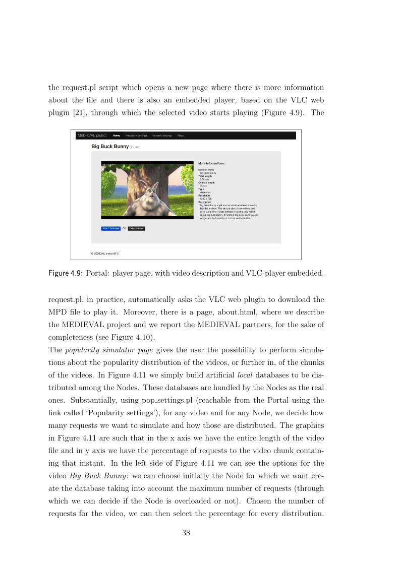
the request.pl script which opens a new page where there is more information
about the file and there is also an embedded player, based on the VLC web
plugin [21], through which the selected video starts playing (Figure 4.9). The
Figure 4.9: Portal: player page, with video description and VLC-player embedded.
request.pl, in practice, automatically asks the VLC web plugin to download the
MPD file to play it. Moreover, there is a page, about.html, where we describe
the MEDIEVAL project and we report the MEDIEVAL partners, for the sake of
completeness (see Figure 4.10).
The popularity simulator page gives the user the possibility to perform simula-
tions about the popularity distribution of the videos, or further in, of the chunks
of the videos. In Figure 4.11 we simply build artificial local databases to be dis-
tributed among the Nodes. These databases are handled by the Nodes as the real
ones. Substantially, using pop settings.pl (reachable from the Portal using the
link called ‘Popularity settings’), for any video and for any Node, we decide how
many requests we want to simulate and how those are distributed. The graphics
in Figure 4.11 are such that in the x axis we have the entire length of the video
file and in y axis we have the percentage of requests to the video chunk contain-
ing that instant. In the left side of Figure 4.11 we can see the options for the
video Big Buck Bunny : we can choose initially the Node for which we want cre-
ate the database taking into account the maximum number of requests (through
which we can decide if the Node is overloaded or not). Chosen the number of
requests for the video, we can then select the percentage for every distribution.
38
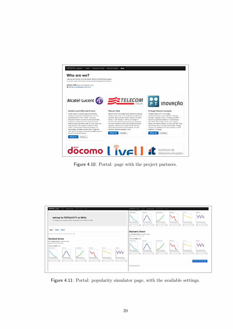
Figure 4.10: Portal: page with the project partners.
Figure 4.11: Portal: popularity simulator page, with the available settings.
39
The possibility are: decreasing exp, gaussian, increasing exp, searching, view all
and jumping. We can simply set the distribution to 100% gaussian, for example,
and see that in the Node the chunks stored are those in the middle of the entire
video length.
After setting the parameters, we can click the button ‘Save the popularity set-
ting’, as reported in the right side of Figure 4.11. With this, after some checks
for percentages and number of requests (within specified bounds), we recall Sim-
CreateDBs.pl which creates the database, following the structure reported for
the local database, with the correct name for each one. Then SimSendDBs.pl
is the scripts that periodically uploads these to the specific Node. This action
continuously run and through it we can change the popularity distribution asymp-
totically, which means we continue to upload the same database (until we do not
further change it) to the Node and finally we can see that in the local cache we
have the chunks following the distribution values of the database. This requires
some uploads since the changes of the popularity values are not instantaneous,
but are carried out weighting them and considering also the average values.
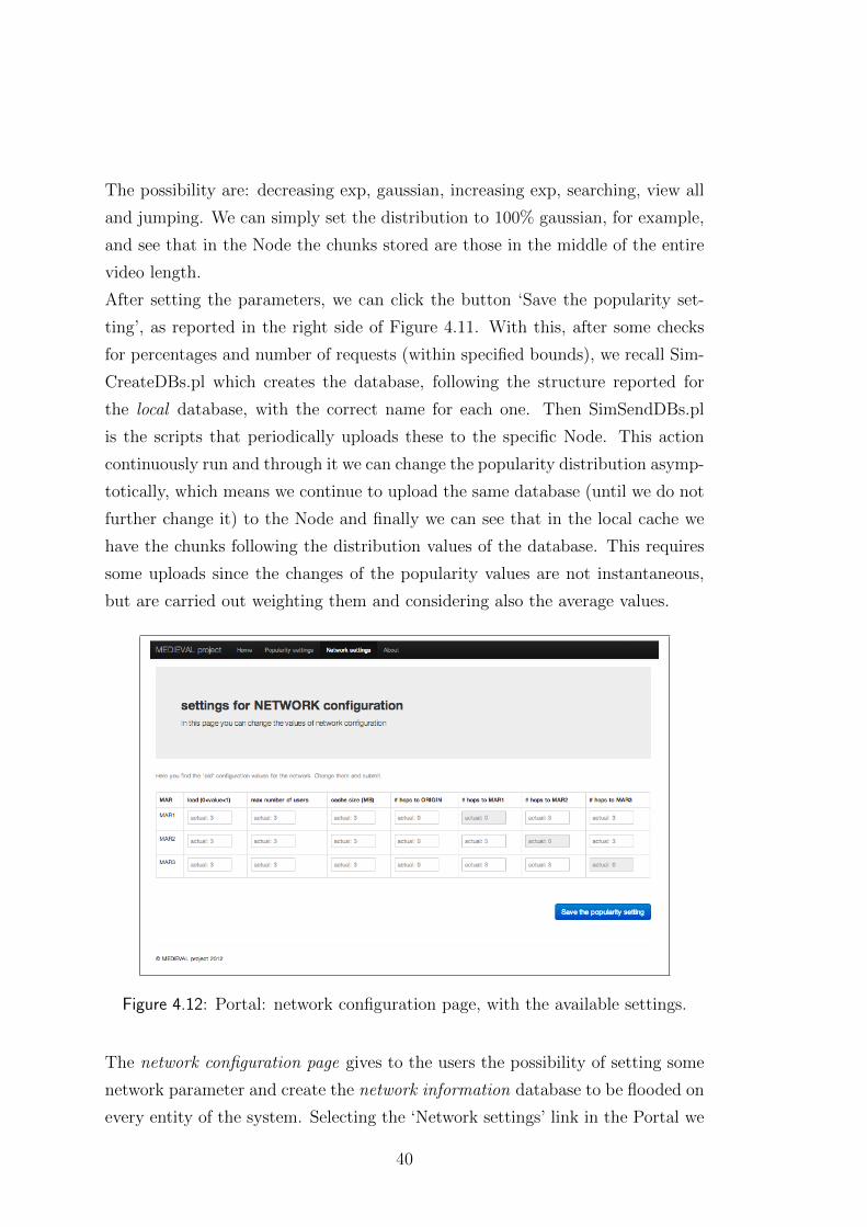
Figure 4.12: Portal: network configuration page, with the available settings.
The network configuration page gives to the users the possibility of setting some
network parameter and create the network information database to be flooded on
every entity of the system. Selecting the ‘Network settings’ link in the Portal we
40
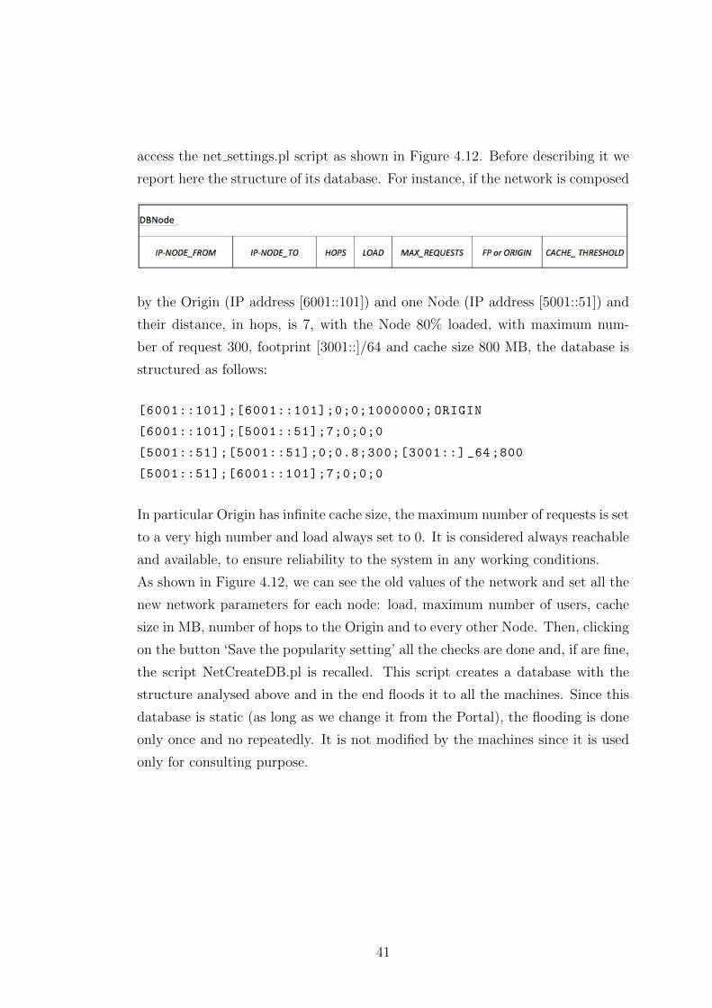
access the net settings.pl script as shown in Figure 4.12. Before describing it we
report here the structure of its database. For instance, if the network is composed
by the Origin (IP address [6001::101]) and one Node (IP address [5001::51]) and
their distance, in hops, is 7, with the Node 80% loaded, with maximum num-
ber of request 300, footprint [3001::]/64 and cache size 800 MB, the database is
structured as follows:
[6001::101];[6001::101];0;0;1000000; ORIGIN
[6001::101];[5001::51];7;0;0;0
[5001::51];[5001::51];0;0.8;300;[3001::] _64 ;800
[5001::51];[6001::101];7;0;0;0
In particular Origin has infinite cache size, the maximum number of requests is set
to a very high number and load always set to 0. It is considered always reachable
and available, to ensure reliability to the system in any working conditions.
As shown in Figure 4.12, we can see the old values of the network and set all the
new network parameters for each node: load, maximum number of users, cache
size in MB, number of hops to the Origin and to every other Node. Then, clicking
on the button ‘Save the popularity setting’ all the checks are done and, if are fine,
the script NetCreateDB.pl is recalled. This script creates a database with the
structure analysed above and in the end floods it to all the machines. Since this
database is static (as long as we change it from the Portal), the flooding is done
only once and no repeatedly. It is not modified by the machines since it is used
only for consulting purpose.
41
4.3 Interfaces
In Chapter 3 we listed the interfaces involved in the CDN module. We now gives
the implementation details of our interfaces.
• DM CDNNC If is implemented using DM.pl and DBNodeUpload.pl
Requests and Response messages are HTTP connections, made with sock-
ets.
– DM CDNNC CDNUpdate made using the main database;
– DM CDNNC CDNStatus made using network information and local
databases;
– DM CDNNC functions use the information obtained by DBNodeU-
pload.pl.
All these functions are sent to CDNNC pop.pl that executes the commands.
• The CDNNC CDNnode If is implemented using CDNNC pop.pl
Requests and Response messages are HTTP connections, made with sock-
ets.
– CDNNC CDNnode CDNUpdate executes send file and delete file in-
structions;
– CDNNC CDNnode CDNStatus executes free space and activenode in-
structions.
• The DM AM If is implemented using DM.pl
Requests and Response messages are HTTP connections, made with sock-
ets.
– This interface is implemented together with DM.pl (function man-
age file inside that file).
– Moreover, we implemented serverDM.pl that interacts with DM.pl pro-
cess to obtain popularity information to reply to the requests from the
Nodes.
42
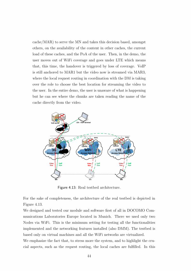
4.4 Real testbed implementation
Our framework is implemented in a real testbed which makes it possible to assess
the performance implemented functionalities. In our case, we test the networking
features and the popularity management concept. This is important also for the
testing of communication with the other modules of the system. We describe the
test scenario as the following use case [7]:
A user through his mobile node (MN) is accessing both a video service
(Video flow) and VoIP (VoIP flow) when connected to the first PoA
(MAR1), that offers 3G connectivity. He is playing the video using
VLC Media Player and DASH. The MPD is downloaded and the
player starts to request the chunks listed in it. All the HTTP requests
pass through the request routing in the MAR, which intercepts and
analyses all of them and if the chunks of the video are available in the
local cache (co-located with the MAR), the request is forwarded to
the local cache and the requested chunk is replied directly from there.
Since the first chunks of the video are, in general, the more popular,
also in the demo the first minutes of the video are available in the local
cache, and the user is thus, retrieving the chunks from it. The user
in the meantime is moving and at a certain point his MN discovers
a WiFi connectivity PoA (MAR2) that is offloaded or at least is less
loaded than the previous PoA; due to this it triggers an handover due
to transport optimization and in the end it is connected to MAR2.
Now the video flow, that is not anchored, goes through this PoA and
on the contrary VoIP flow stays anchored to MAR1 (the traffic is
tunnelled between the MAR anchoring the flow and the MAR serving
the MN). This happens because the VoIP flow is not as heavy as
video. The local cache in MAR2 also contains the requested chunks
for the video and, thus, the video is now streamed from his cache;
but, since the video continues and the chunks towards the end of the
video are no longer as popular as the first minutes of the video, they
are not available in the local cache. Then the MAR, upon receiving
a request for these chunks, sends a request to the DM to check the
best location of them. The DM selects the best cache (Origin or other
43
cache/MAR) to serve the MN and takes this decision based, amongst
others, on the availability of the content in other caches, the current
load of these caches, and the PoA of the user. Then, in the demo, the
user moves out of WiFi coverage and goes under LTE which means
that, this time, the handover is triggered by loss of coverage. VoIP
is still anchored to MAR1 but the video now is streamed via MAR3,
where the local request routing in coordination with the DM is taking
over the role to choose the best location for streaming the video to
the user. In the entire demo, the user is unaware of what is happening
but he can see where the chunks are taken reading the name of the
cache directly from the video.
DEMONSTRATION 1 MOBILITY AND CDN SCENARIO
DEMO DESCRIPTION
Dynamic & Distributed Mobility Management (DMM) concept: “anchors to the edge” as deployed in the default gateway of the mobile node
Intelligent video distribution systems (distributed caching with central control)
Integration of CDN nodes/caches inside the mobile network IP flow selected mobility Logical Interface concept at the MN (the radio interfaces are
grouped under a single virtual network interface seen by upper layers)
IEEE 802.21 as cross layer solution for mobility optimization Unified management for both 3GPP and not 3GPP accesses Economic benefits for operators (this may vary on data traffic
patterns and/or mobile network topologies)
A mobile node MN is accessing both a video service (Video flow) and VoIP (VoIP flow)
The video is available in the Video Server and caches The caches are co-located with MARs While the mobile node is moving around, the best cache
is selected to serve it Different handover triggers mechanisms/logic
Sequence of the demo:
1. MN attaches to MAR1 (3G technology) and starts/gets a
VoIP flow 2. MN starts video application and gets video (from cache1
or VoD Server) 3. MN discovers a WiFi PoA (MAR2) and attaches to it:
Handover triggered by the network due to caching optimization
4. VoIP flow stays anchored to MAR1 (the traffic is tunnelled between the MAR anchoring the flow and the MAR serving the MN), video flow comes now from cache2
5. MN moves out of WLAN coverage and goes under MAR3 (LTE): handover triggered by loss of coverage
6. VoIP is still anchored to MAR1. The video flow comes from cache3
KEY CONCEPTS & BENEFITS
September 2012, Alcatel-Lucent Bell Labs, Paris
Source
RRDM
MobileNode
CDN CacheCDN CacheCDN Cache
MobileNode
ContentPortal
LTEAccess Network
WiFiAccess Network
3GAccess Network
VoD server
Cache1 Cache2 Cache3
MAR1 MAR2 MAR3
CN – VoIP terminal
MN MNMN
Video flow
Video flow
Video flow
VoIP flow
VoIP flow
VoIP flow
MAR = Mobility Access RouterFigure 4.13: Real testbed architecture.
For the sake of completeness, the architecture of the real testbed is depicted in
Figure 4.13.
We designed and tested our module and software first of all in DOCOMO Com-
munications Laboratories Europe located in Munich. There we used only two
Nodes via WiFi. This is the minimum setting for testing all the functionalities
implemented and the networking features installed (also DMM). The testbed is
based only on virtual machines and all the WiFi networks are virtualized.
We emphasize the fact that, to stress more the system, and to highlight the cru-
cial aspects, such as the request routing, the local caches are fulfilled. In this
44
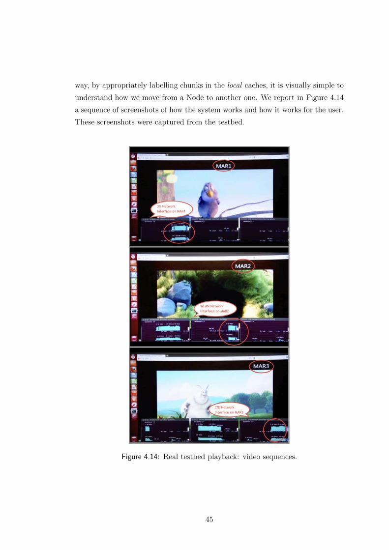
way, by appropriately labelling chunks in the local caches, it is visually simple to
understand how we move from a Node to another one. We report in Figure 4.14
a sequence of screenshots of how the system works and how it works for the user.
These screenshots were captured from the testbed.
Figure 4.14: Real testbed playback: video sequences.
45

46
Chapter 5
Results
We remind the description of the features in Section 3.2 and we analyse in details
how these features are built and how our system works, based on the implemen-
tation details reported in Chapter 4. We first describe the benefits of segmented
video streams in combination with request routing, followed by the assessments
of popularity-based caching, the robustness of the in-network CDN system and
the session continuity during handovers.
5.1 Segmented videos and request routing
In order to access the MCDN functionalities, we use a video streaming scenario
where the video is segmented into chunks (DASH). Segmented videos are usually
used in peer-to-peer video applications to overcome the limitation of asymmetri-
cal Internet access, or in adaptive video streaming, allowing the client to adapt
to dynamic bandwidth conditions. In the latter approach, the client can choose
among video coding scheme when requesting the next chunk. The client is in-
formed about available bitrates in the form of ‘manifest’ file (called MPD file for
DASH) during the session setup. The manifest file for a video contains infor-
mation about the URLs of each combination of encoding and chunk, i.e., a list
of URLs for all chunks of encoding 1, chunks of encoding 2, and so on. In our
project we use segmented video in a novel way to also 1) introduce in-network
caches and 2) adapt to the mobility of the user. We realized, in the testbed, the
redirection of requests to the appropriate copy of the segment, via a transparent
proxy at the Node. The proxy is intercepting all HTTP requests (this could also
47
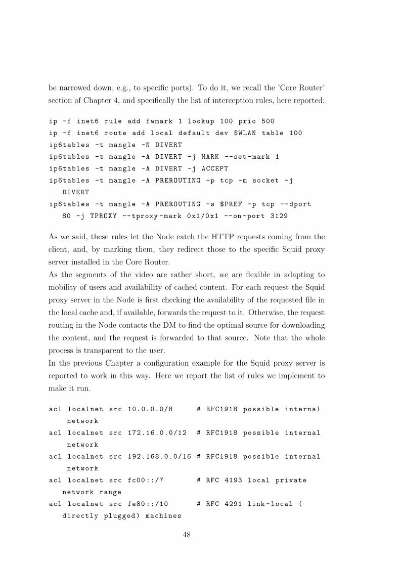
be narrowed down, e.g., to specific ports). To do it, we recall the ’Core Router’
section of Chapter 4, and specifically the list of interception rules, here reported:
ip -f inet6 rule add fwmark 1 lookup 100 prio 500
ip -f inet6 route add local default dev $WLAN table 100
ip6tables -t mangle -N DIVERT
ip6tables -t mangle -A DIVERT -j MARK --set -mark 1
ip6tables -t mangle -A DIVERT -j ACCEPT
ip6tables -t mangle -A PREROUTING -p tcp -m socket -j
DIVERT
ip6tables -t mangle -A PREROUTING -s $PREF -p tcp --dport
80 -j TPROXY --tproxy -mark 0x1/0x1 --on -port 3129
As we said, these rules let the Node catch the HTTP requests coming from the
client, and, by marking them, they redirect those to the specific Squid proxy
server installed in the Core Router.
As the segments of the video are rather short, we are flexible in adapting to
mobility of users and availability of cached content. For each request the Squid
proxy server in the Node is first checking the availability of the requested file in
the local cache and, if available, forwards the request to it. Otherwise, the request
routing in the Node contacts the DM to find the optimal source for downloading
the content, and the request is forwarded to that source. Note that the whole
process is transparent to the user.
In the previous Chapter a configuration example for the Squid proxy server is
reported to work in this way. Here we report the list of rules we implement to
make it run.
acl localnet src 10.0.0.0/8 # RFC1918 possible internal
network
acl localnet src 172.16.0.0/12 # RFC1918 possible internal
network
acl localnet src 192.168.0.0/16 # RFC1918 possible internal
network
acl localnet src fc00 ::/7 # RFC 4193 local private
network range
acl localnet src fe80 ::/10 # RFC 4291 link -local (
directly plugged) machines
48
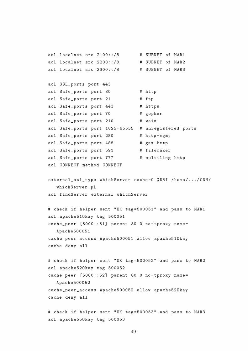
acl localnet src 2100::/8 # SUBNET of MAR1
acl localnet src 2200::/8 # SUBNET of MAR2
acl localnet src 2300::/8 # SUBNET of MAR3
acl SSL_ports port 443
acl Safe_ports port 80 # http
acl Safe_ports port 21 # ftp
acl Safe_ports port 443 # https
acl Safe_ports port 70 # gopher
acl Safe_ports port 210 # wais
acl Safe_ports port 1025 -65535 # unregistered ports
acl Safe_ports port 280 # http -mgmt
acl Safe_ports port 488 # gss -http
acl Safe_ports port 591 # filemaker
acl Safe_ports port 777 # multiling http
acl CONNECT method CONNECT
external_acl_type whichServer cache =0 %URI /home /.../ CDN/
whichServer.pl
acl findServer external whichServer
# check if helper sent "OK tag =500051" and pass to MAR1
acl apache51Okay tag 500051
cache_peer [5000::51] parent 80 0 no-tproxy name=
Apache500051
cache_peer_access Apache500051 allow apache51Okay
cache deny all
# check if helper sent "OK tag =500052" and pass to MAR2
acl apache52Okay tag 500052
cache_peer [5000::52] parent 80 0 no-tproxy name=
Apache500052
cache_peer_access Apache500052 allow apache52Okay
cache deny all
# check if helper sent "OK tag =500053" and pass to MAR3
acl apache55Okay tag 500053
49
cache_peer [5000::53] parent 80 0 no-tproxy name=
Apache500053
cache_peer_access Apache500053 allow apache53Okay
cache deny all
http_access allow manager localhost
http_access deny manager
http_access deny !Safe_ports
http_access deny CONNECT !SSL_ports
http_access allow findServer
http_access allow localhost
http_access allow to_localhost
http_access allow localnet
http_access allow all
cache deny all
http_port 3128
http_port 3129 tproxy
With this Squid proxy server configuration, installed in each Node, we can process
every request, recalling the script whichServer.pl through the line ’external acl type
whichServer cache=0 %URI home...CDNwhichServer.pl’. The script is able
to read the content requested and to check its availability. By being able to dy-
namically redirect requests to any available copy of the requested content, the
CDN system also supports traffic optimisation actions, like selecting a different
path between application and source, e.g., through changing the wireless access
(vertical or horizontal handover) or selecting a different copy of the requested
content in the network (e.g., caching Node).
5.2 Popularity-based caching
The popularity-aware content placement algorithm is accessed using a request
generator implemented in the testbed (see Figure 4.11). As we are not able to
connect hundreds or thousands of clients to the testbed, generating real requests
for videos, the request generator can be used to generate artificial requests at
50
different Nodes. Via GUI, we can specify the regional popularity of the different
videos available in the testbed, as well as compose the viewing behaviour for each
video. For example users usually start watching the movie from the beginning,
but after some time a user may stop the video, as he does not like the movie or
he is distracted by some other issue. Thus, the popularity of chunks of a spe-
cific movie is fairly high for the first chunks and getting smaller for last chunks
(‘decreasing exp.’ distribution). For other types of videos, the popularity distri-
bution of the chunks may be different, e.g., a user may skip through a tutorial
video to search for a particular topic he is interested in (distribution ‘jumping’),
or he already knows a certain sequence within a YouTube video where he is di-
rectly jumping to that scene but not exactly hitting the right spot (distribution
‘Gaussian’). The popularity distribution can be changed dynamically during the
simulation.
The request generator takes the input from the popularity distribution and emu-
lates user requests for the chunks of all videos based on the specified popularity
distribution. The number of requests for each chunk is not deterministic, rather
a random function that ensures small variations in the requested pattern. The
new pattern is monitored at the Node and an aggregated report is periodically
sent to the AM. The DM periodically requests the updated content popularity,
and depending on the specified reporting and on updated frequencies, DM starts
adapting the content in the local caches to the new content popularity. Figure 4.4
shows the content available in the cache located at Node resulting from a spe-
cific popularity distribution. For the video ‘Big Buck Bunny’, the first 4 chunks
are stored in the cache, whereas later chunks are below the dynamic popularity
threshold and, thus, are not cached locally. This threshold is calculated weighting
instantaneous and averaged values of popularity, in order to avoid useless actions.
Basically, the updated frequencies determine the reaction time of the CDN sys-
tem towards changes in the content popularity. There is a trade-off between low
update frequencies, i.e., low overhead in signalling and processing, and fast reac-
tion to quick changes, e.g., in case of flash crowds. The operator may also decide
to implement a more complex algorithm in the request routing capable of rec-
ognizing sudden changes of the popularity and triggering the DM by sending an
immediate report. In the real testbed, we decided to study the trade-off between
overhead and speed. Then, we are able to demonstrate the impact of changing
51
the popularity of the cached content within a reasonable time of a few minutes.
The prototype behaves as expected and is correctly adapting to the new content
popularity distribution.
This feature is realized inside the Portal (Chapter 4), and it is reachable, specif-
ically, through the popularity simulator page. We chose 3 ‘standard’ videos and
realize one generator for each Node. In this way we can stress the system and
prove that it works also for a large number of requests.
5.3 Robustness of the CDN component
Our goal in this section is to show the robustness of the system in case of failures
of Nodes or packet losses. If a Node fails, the DM will not receive any message
from such Node and after a timer expires, it will redirect incoming requests to
other caches or to the Origin server. In the worst case, the user may realize this
outage with a short disruption of the playback, yet, in most cases, the applica-
tion can survive several seconds thanks to its internal buffer. In the meantime
the request routing will be aware of the non-responsive Node and, assuming a
re-transmission-like algorithm in the application, the next request for the missing
chunk will be redirected to another node.
In case of failure of the AM, there is no possibility to update the content pop-
ularity distribution. This means, the DM is not aware of changes in popularity
and, thus, will not be able to update the content in the Nodes. This implies
that the system will not operate in optimal mode, but as severe changes in the
popularity distribution are quite rare, the system will still show almost optimal
performance. Even in case of one video, e.g., some top news, suddenly being re-
quested in a flash-crowd like manner, the system would still perform better than
a system without any in-network caching functionality.
Similarly, if a CDNNC fails, the communication with the attached Node(s) is
lost. Yet, requests can still be forwarded to these Node(s), as long as they are
still up and running. Only content update and status request messages cannot
be processed, thus, the Node will not be able to change its cached content.
52
5.4 Session continuity during handovers
The system is able to provide a non-anchored application-layer-based mobility
support for videos. For each request of a chunk a new HTTP is set up. When the
user moves and connects to a new PoA, an HTTP session for the next request
will be established through the new PoA. This means, the ongoing playout of the
video can continue with the next segment. In addition, the mobility management
is applied to the currently streamed segment, thus, by anchoring that flow, the
HTTP session is not lost and the segment is streaming to the end user. In that
way, we can provide a continuous playback of the video to the user. The mobility
management must not anchor the flow during the whole video session, but only
seconds to few minutes to complete the started segment.
The performance of this application-layer-based mobility support is mainly de-
pendent on the duration of the segments. Short segments enable high flexibility
during mobility, and the anchor for the ongoing segment is only needed for a
short period. However, in current applications the anchor must be set up in any
case in order to provide smooth playback of the video and avoid problems. Short
segments increase the overhead of the system linearly: the size of the manifest
file is almost increasing linearly with the number of the referred segments, the
request routing interrupts each segment, and the overhead for establishing the
HTTP connections as well as the number of packets to transmit will increase
with shorter segments. Thus, a trade-off between flexibility and overhead must
be considered. In our prototype, we tested several lengths of the segments (from
1 second to 15 seconds), and finally choose a duration of 5 seconds to have a
stable system, and being able to demonstrate the non-anchored handover within
a reasonable response time.
As a result we report in the next page the sequence of messages travelling through
the Nodes during handovers performed in the real testbed, to highlight the sta-
bility and continuity of the video session.
53
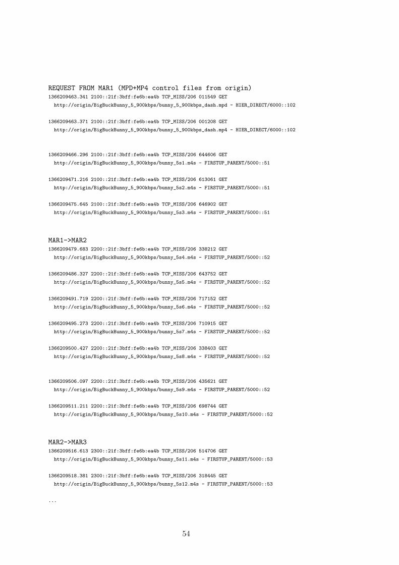
REQUEST FROM MAR1 (MPD+MP4 control files from origin)1366209463.341 2100::21f:3bff:fe6b:ea4b TCP_MISS/206 011549 GET
http://origin/BigBuckBunny_5_900kbps/bunny_5_900kbps_dash.mpd - HIER_DIRECT/6000::102
1366209463.371 2100::21f:3bff:fe6b:ea4b TCP_MISS/206 001208 GET
http://origin/BigBuckBunny_5_900kbps/bunny_5_900kbps_dash.mp4 - HIER_DIRECT/6000::102
1366209466.296 2100::21f:3bff:fe6b:ea4b TCP_MISS/206 644606 GET
http://origin/BigBuckBunny_5_900kbps/bunny_5s1.m4s - FIRSTUP_PARENT/5000::51
1366209471.216 2100::21f:3bff:fe6b:ea4b TCP_MISS/206 613061 GET
http://origin/BigBuckBunny_5_900kbps/bunny_5s2.m4s - FIRSTUP_PARENT/5000::51
1366209475.645 2100::21f:3bff:fe6b:ea4b TCP_MISS/206 646902 GET
http://origin/BigBuckBunny_5_900kbps/bunny_5s3.m4s - FIRSTUP_PARENT/5000::51
MAR1->MAR21366209479.683 2200::21f:3bff:fe6b:ea4b TCP_MISS/206 338212 GET
http://origin/BigBuckBunny_5_900kbps/bunny_5s4.m4s - FIRSTUP_PARENT/5000::52
1366209486.327 2200::21f:3bff:fe6b:ea4b TCP_MISS/206 643752 GET
http://origin/BigBuckBunny_5_900kbps/bunny_5s5.m4s - FIRSTUP_PARENT/5000::52
1366209491.719 2200::21f:3bff:fe6b:ea4b TCP_MISS/206 717152 GET
http://origin/BigBuckBunny_5_900kbps/bunny_5s6.m4s - FIRSTUP_PARENT/5000::52
1366209495.273 2200::21f:3bff:fe6b:ea4b TCP_MISS/206 710915 GET
http://origin/BigBuckBunny_5_900kbps/bunny_5s7.m4s - FIRSTUP_PARENT/5000::52
1366209500.427 2200::21f:3bff:fe6b:ea4b TCP_MISS/206 338403 GET
http://origin/BigBuckBunny_5_900kbps/bunny_5s8.m4s - FIRSTUP_PARENT/5000::52
1366209506.097 2200::21f:3bff:fe6b:ea4b TCP_MISS/206 435621 GET
http://origin/BigBuckBunny_5_900kbps/bunny_5s9.m4s - FIRSTUP_PARENT/5000::52
1366209511.211 2200::21f:3bff:fe6b:ea4b TCP_MISS/206 698744 GET
http://origin/BigBuckBunny_5_900kbps/bunny_5s10.m4s - FIRSTUP_PARENT/5000::52
MAR2->MAR31366209516.613 2300::21f:3bff:fe6b:ea4b TCP_MISS/206 514706 GET
http://origin/BigBuckBunny_5_900kbps/bunny_5s11.m4s - FIRSTUP_PARENT/5000::53
1366209518.381 2300::21f:3bff:fe6b:ea4b TCP_MISS/206 318445 GET
http://origin/BigBuckBunny_5_900kbps/bunny_5s12.m4s - FIRSTUP_PARENT/5000::53
...
54
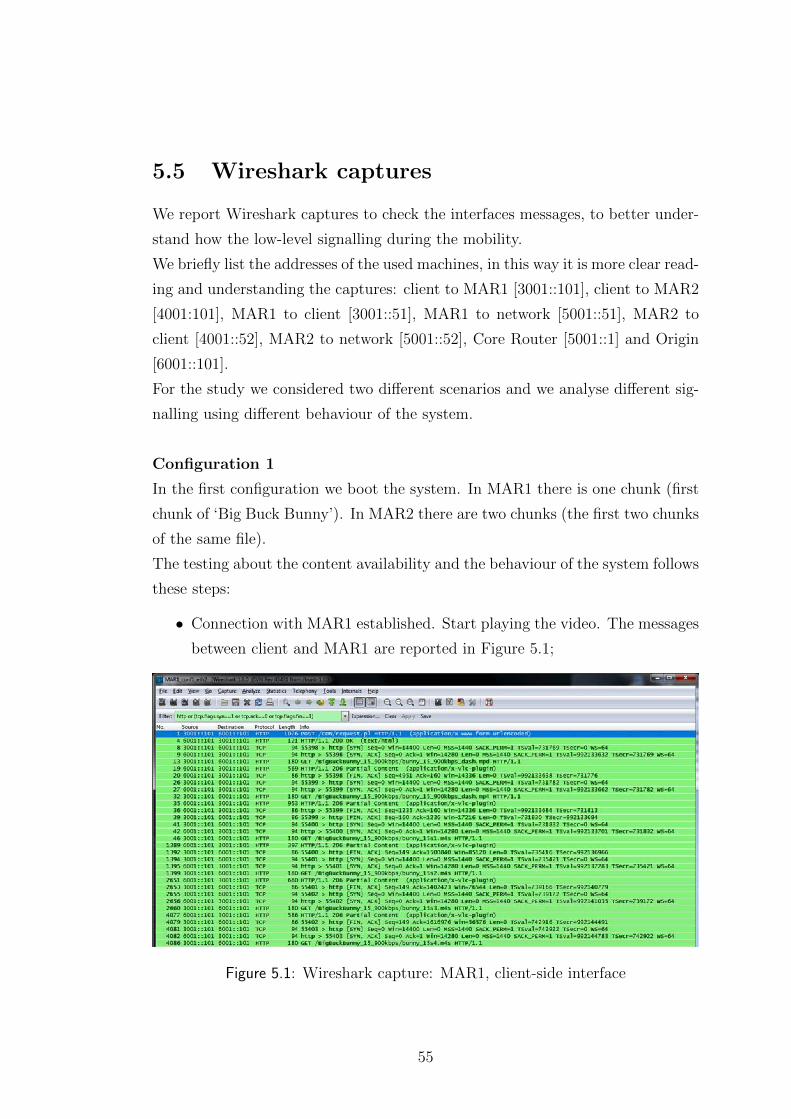
5.5 Wireshark captures
We report Wireshark captures to check the interfaces messages, to better under-
stand how the low-level signalling during the mobility.
We briefly list the addresses of the used machines, in this way it is more clear read-
ing and understanding the captures: client to MAR1 [3001::101], client to MAR2
[4001:101], MAR1 to client [3001::51], MAR1 to network [5001::51], MAR2 to
client [4001::52], MAR2 to network [5001::52], Core Router [5001::1] and Origin
[6001::101].
For the study we considered two different scenarios and we analyse different sig-
nalling using different behaviour of the system.
Configuration 1
In the first configuration we boot the system. In MAR1 there is one chunk (first
chunk of ‘Big Buck Bunny’). In MAR2 there are two chunks (the first two chunks
of the same file).
The testing about the content availability and the behaviour of the system follows
these steps:
• Connection with MAR1 established. Start playing the video. The messages
between client and MAR1 are reported in Figure 5.1;
Figure 5.1: Wireshark capture: MAR1, client-side interface
55
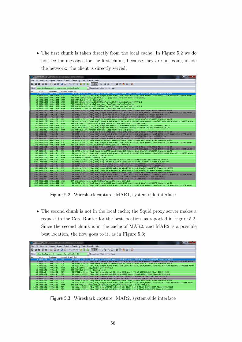
• The first chunk is taken directly from the local cache. In Figure 5.2 we do
not see the messages for the first chunk, because they are not going inside
the network: the client is directly served;
Figure 5.2: Wireshark capture: MAR1, system-side interface
• The second chunk is not in the local cache; the Squid proxy server makes a
request to the Core Router for the best location, as reported in Figure 5.2.
Since the second chunk is in the cache of MAR2, and MAR2 is a possible
best location, the flow goes to it, as in Figure 5.3;
Figure 5.3: Wireshark capture: MAR2, system-side interface
56
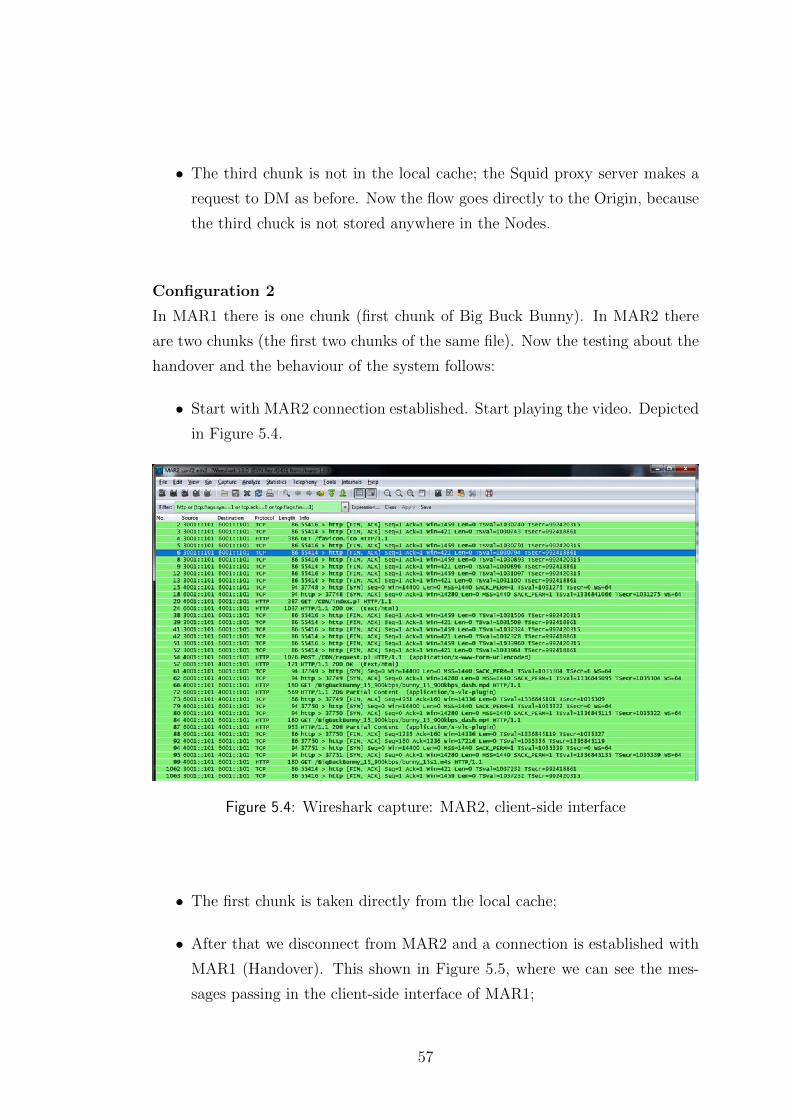
• The third chunk is not in the local cache; the Squid proxy server makes a
request to DM as before. Now the flow goes directly to the Origin, because
the third chuck is not stored anywhere in the Nodes.
Configuration 2
In MAR1 there is one chunk (first chunk of Big Buck Bunny). In MAR2 there
are two chunks (the first two chunks of the same file). Now the testing about the
handover and the behaviour of the system follows:
• Start with MAR2 connection established. Start playing the video. Depicted
in Figure 5.4.
Figure 5.4: Wireshark capture: MAR2, client-side interface
• The first chunk is taken directly from the local cache;
• After that we disconnect from MAR2 and a connection is established with
MAR1 (Handover). This shown in Figure 5.5, where we can see the mes-
sages passing in the client-side interface of MAR1;
57
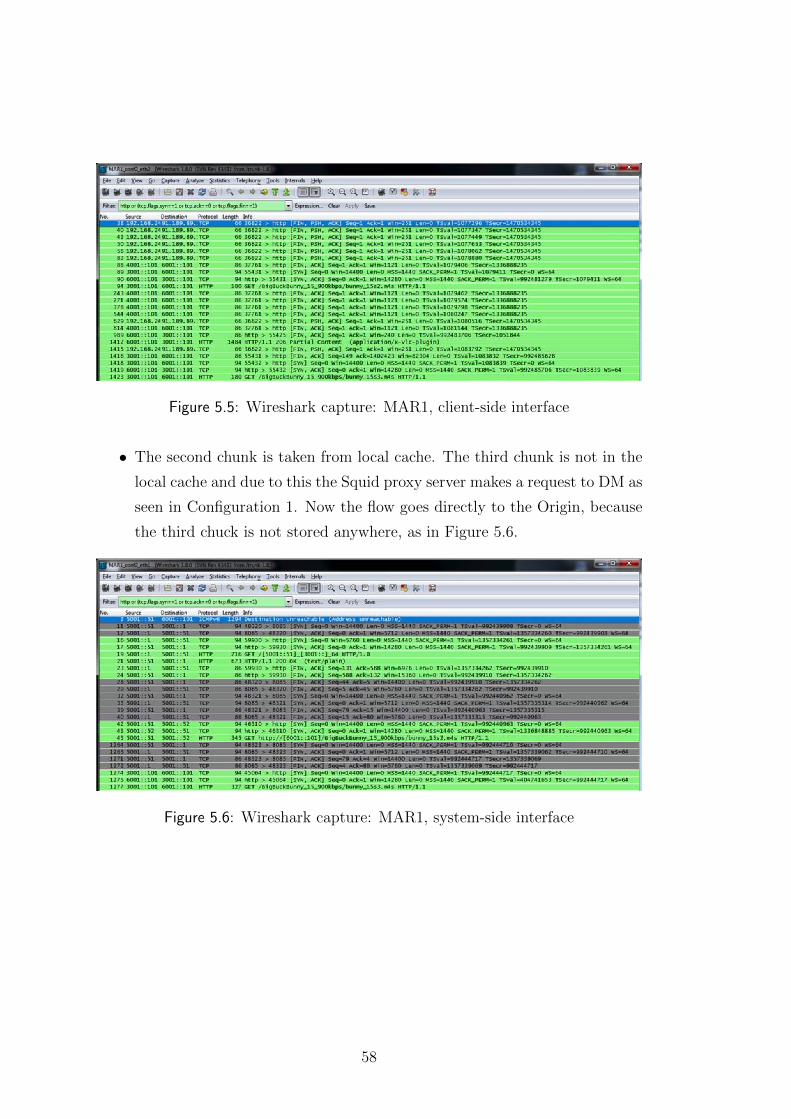
Figure 5.5: Wireshark capture: MAR1, client-side interface
• The second chunk is taken from local cache. The third chunk is not in the
local cache and due to this the Squid proxy server makes a request to DM as
seen in Configuration 1. Now the flow goes directly to the Origin, because
the third chuck is not stored anywhere, as in Figure 5.6.
Figure 5.6: Wireshark capture: MAR1, system-side interface
58
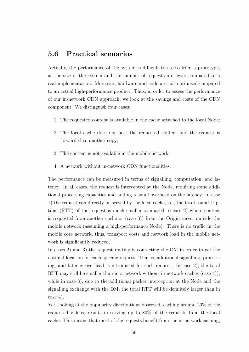
5.6 Practical scenarios
Actually, the performance of the system is difficult to assess from a prototype,
as the size of the system and the number of requests are fewer compared to a
real implementation. Moreover, hardware and code are not optimised compared
to an actual high-performance product. Thus, in order to assess the performance
of our in-network CDN approach, we look at the savings and costs of the CDN
component. We distinguish four cases:
1. The requested content is available in the cache attached to the local Node;
2. The local cache does not host the requested content and the request is
forwarded to another copy;
3. The content is not available in the mobile network;
4. A network without in-network CDN functionalities.
The performance can be measured in terms of signalling, computation, and la-
tency. In all cases, the request is intercepted at the Node, requiring some addi-
tional processing capacities and adding a small overhead on the latency. In case
1) the request can directly be served by the local cache, i.e., the total round-trip-
time (RTT) of the request is much smaller compared to case 2) where content
is requested from another cache or (case 3)) from the Origin server outside the
mobile network (assuming a high-performance Node). There is no traffic in the
mobile core network, thus, transport costs and network load in the mobile net-
work is significantly reduced.
In cases 2) and 3) the request routing is contacting the DM in order to get the
optimal location for each specific request. That is, additional signalling, process-
ing, and latency overhead is introduced for each request. In case 2), the total
RTT may still be smaller than in a network without in-network caches (case 4)),
while in case 3), due to the additional packet interception at the Node and the
signalling exchange with the DM, the total RTT will be definitely larger than in
case 4).
Yet, looking at the popularity distributions observed, caching around 20% of the
requested videos, results in serving up to 80% of the requests from the local
cache. This means that most of the requests benefit from the in-network caching,
59
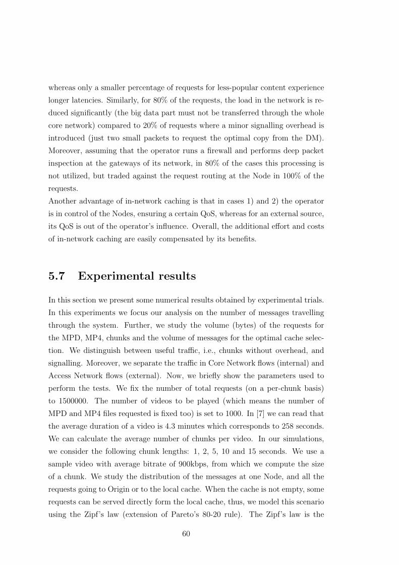
whereas only a smaller percentage of requests for less-popular content experience
longer latencies. Similarly, for 80% of the requests, the load in the network is re-
duced significantly (the big data part must not be transferred through the whole
core network) compared to 20% of requests where a minor signalling overhead is
introduced (just two small packets to request the optimal copy from the DM).
Moreover, assuming that the operator runs a firewall and performs deep packet
inspection at the gateways of its network, in 80% of the cases this processing is
not utilized, but traded against the request routing at the Node in 100% of the
requests.
Another advantage of in-network caching is that in cases 1) and 2) the operator
is in control of the Nodes, ensuring a certain QoS, whereas for an external source,
its QoS is out of the operator’s influence. Overall, the additional effort and costs
of in-network caching are easily compensated by its benefits.
5.7 Experimental results
In this section we present some numerical results obtained by experimental trials.
In this experiments we focus our analysis on the number of messages travelling
through the system. Further, we study the volume (bytes) of the requests for
the MPD, MP4, chunks and the volume of messages for the optimal cache selec-
tion. We distinguish between useful traffic, i.e., chunks without overhead, and
signalling. Moreover, we separate the traffic in Core Network flows (internal) and
Access Network flows (external). Now, we briefly show the parameters used to
perform the tests. We fix the number of total requests (on a per-chunk basis)
to 1500000. The number of videos to be played (which means the number of
MPD and MP4 files requested is fixed too) is set to 1000. In [7] we can read that
the average duration of a video is 4.3 minutes which corresponds to 258 seconds.
We can calculate the average number of chunks per video. In our simulations,
we consider the following chunk lengths: 1, 2, 5, 10 and 15 seconds. We use a
sample video with average bitrate of 900kbps, from which we compute the size
of a chunk. We study the distribution of the messages at one Node, and all the
requests going to Origin or to the local cache. When the cache is not empty, some
requests can be served directly form the local cache, thus, we model this scenario
using the Zipf’s law (extension of Pareto’s 80-20 rule). The Zipf’s law is the
60
way to link the storage percentage of the cache to the number of requests served
directly. If the cache is filled with 10% of popular chunks, we can serve directly
65% of the requests. When the cache is filled with 20% of popular chunks, we
can serve directly 80% of the requests.
Figure 5.7: Traffic volume in CN and AN.
In Figure 5.7, we show the traffic volume as a function of the percentage of stored
chunks in the local cache. We underline that the traffic volume is the sum of in-
ternal and external video flows. We see that the total traffic for short video
chunks (1 and 2 s) is the highest. This is more evident when the cache is almost
empty (left side of the figure). When the cache is full, the chunk length has no
impact on the overall traffic. This is the reason why the number of requests for
the location from which to retrieve the content is high when the cache is empty.
Viceversa, once the cache is full, the requests go to zero due to the fact that
the Node knows locally how to react to the requests. The number of messages
depends on the chunk size, since the requests are sent on a per-chunk basis. The
signalling messages increase the system load but, as we can see in Figure 5.8,
the traffic in the Core Network gets smaller. However, the traffic keeps greater
than zero because of the MPD and MP4 messages, which are retrieved from the
Origin.
61
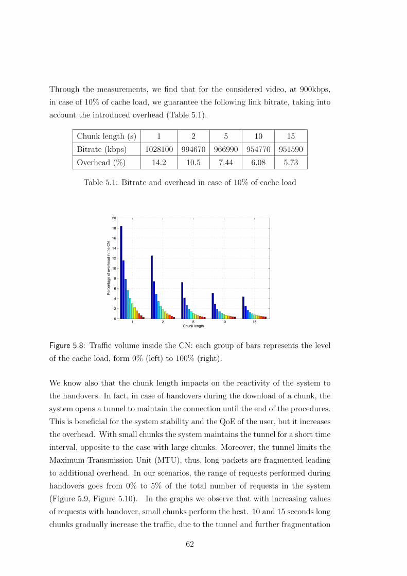
Through the measurements, we find that for the considered video, at 900kbps,
in case of 10% of cache load, we guarantee the following link bitrate, taking into
account the introduced overhead (Table 5.1).
Chunk length (s) 1 2 5 10 15
Bitrate (kbps) 1028100 994670 966990 954770 951590
Overhead (%) 14.2 10.5 7.44 6.08 5.73
Table 5.1: Bitrate and overhead in case of 10% of cache load
1 2 5 10 150
2
4
6
8
10
12
14
16
18
20
Chunk length
Perc
enta
ge o
f ove
rhea
d in
the
CN
Figure 5.8: Traffic volume inside the CN: each group of bars represents the level
of the cache load, form 0% (left) to 100% (right).
We know also that the chunk length impacts on the reactivity of the system to
the handovers. In fact, in case of handovers during the download of a chunk, the
system opens a tunnel to maintain the connection until the end of the procedures.
This is beneficial for the system stability and the QoE of the user, but it increases
the overhead. With small chunks the system maintains the tunnel for a short time
interval, opposite to the case with large chunks. Moreover, the tunnel limits the
Maximum Transmission Unit (MTU), thus, long packets are fragmented leading
to additional overhead. In our scenarios, the range of requests performed during
handovers goes from 0% to 5% of the total number of requests in the system
(Figure 5.9, Figure 5.10). In the graphs we observe that with increasing values
of requests with handover, small chunks perform the best. 10 and 15 seconds long
chunks gradually increase the traffic, due to the tunnel and further fragmentation
62
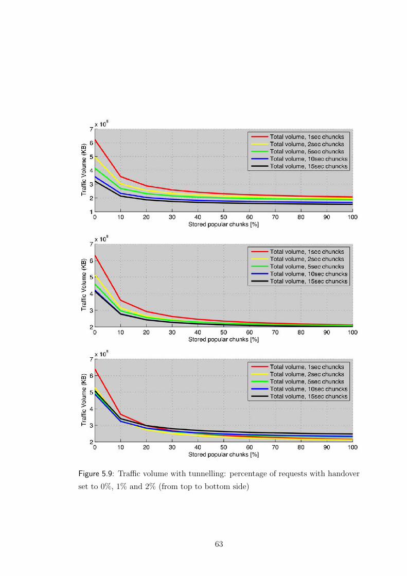
Figure 5.9: Traffic volume with tunnelling: percentage of requests with handover
set to 0%, 1% and 2% (from top to bottom side)
63
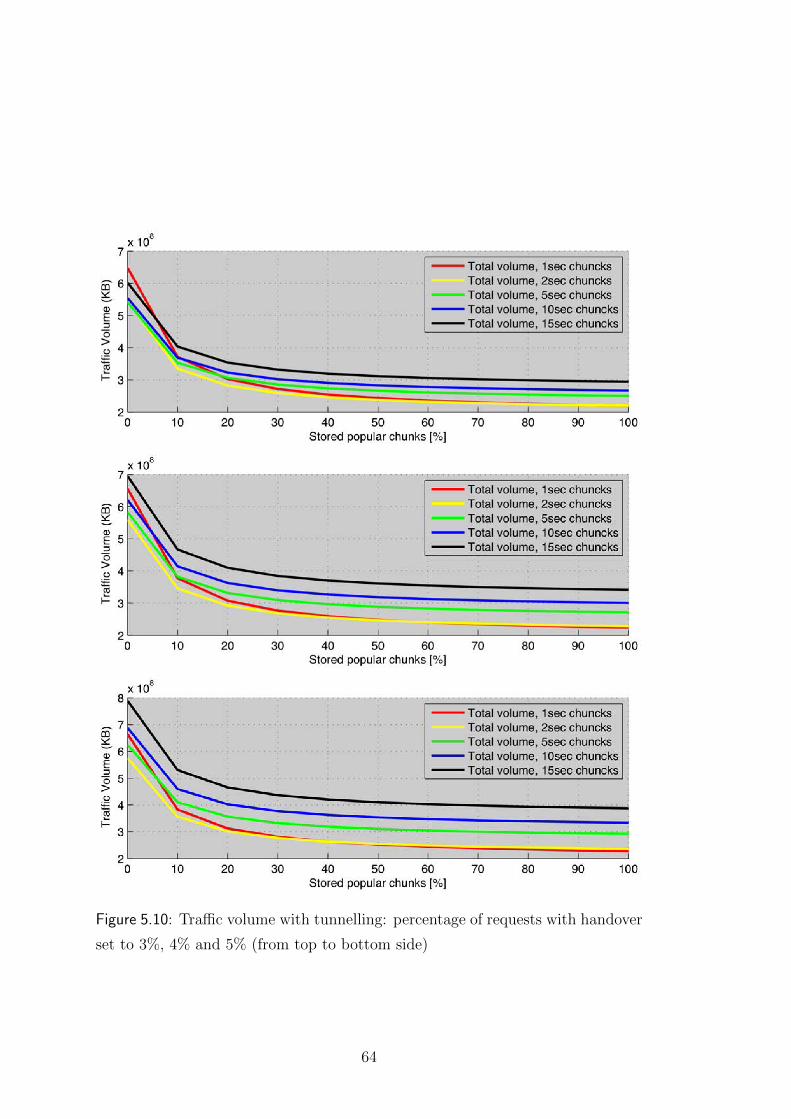
Figure 5.10: Traffic volume with tunnelling: percentage of requests with handover
set to 3%, 4% and 5% (from top to bottom side)
64
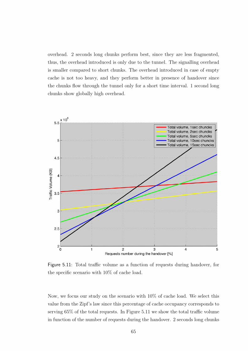
overhead. 2 seconds long chunks perform best, since they are less fragmented,
thus, the overhead introduced is only due to the tunnel. The signalling overhead
is smaller compared to short chunks. The overhead introduced in case of empty
cache is not too heavy, and they perform better in presence of handover since
the chunks flow through the tunnel only for a short time interval. 1 second long
chunks show globally high overhead.
Figure 5.11: Total traffic volume as a function of requests during handover, for
the specific scenario with 10% of cache load.
Now, we focus our study on the scenario with 10% of cache load. We select this
value from the Zipf’s law since this percentage of cache occupancy corresponds to
serving 65% of the total requests. In Figure 5.11 we show the total traffic volume
in function of the number of requests during the handover. 2 seconds long chunks
65
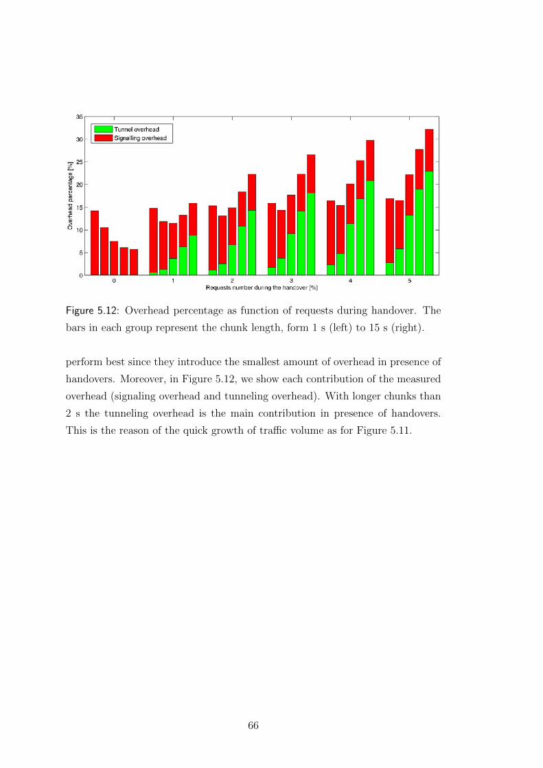
Figure 5.12: Overhead percentage as function of requests during handover. The
bars in each group represent the chunk length, form 1 s (left) to 15 s (right).
perform best since they introduce the smallest amount of overhead in presence of
handovers. Moreover, in Figure 5.12, we show each contribution of the measured
overhead (signaling overhead and tunneling overhead). With longer chunks than
2 s the tunneling overhead is the main contribution in presence of handovers.
This is the reason of the quick growth of traffic volume as for Figure 5.11.
66
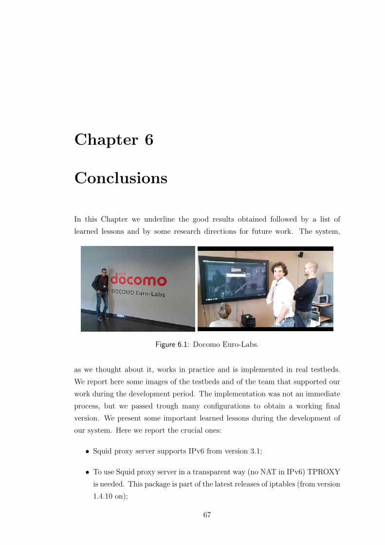
Chapter 6
Conclusions
In this Chapter we underline the good results obtained followed by a list of
learned lessons and by some research directions for future work. The system,
Figure 6.1: Docomo Euro-Labs.
as we thought about it, works in practice and is implemented in real testbeds.
We report here some images of the testbeds and of the team that supported our
work during the development period. The implementation was not an immediate
process, but we passed trough many configurations to obtain a working final
version. We present some important learned lessons during the development of
our system. Here we report the crucial ones:
• Squid proxy server supports IPv6 from version 3.1;
• To use Squid proxy server in a transparent way (no NAT in IPv6) TPROXY
is needed. This package is part of the latest releases of iptables (from version
1.4.10 on);
67
• Ubuntu 10.04 is an old version. We needed to recompile the kernel with
version 2.6.39 to operate with Netfilter. It was necessary to install iptables
with TPROXY;
• To make the system running we studied a particular setting for ip6tables.
We introduced the marking of the packet and the routing of these packets
where needed;
• Packet routing, the critical challenge, was addressed as follows:
– Initially we set up an IPv4 system and we used a simple NAT to
perform the redirection;
– Moving to IPv6 there was a problem of local loop. We worked with
the ports of the Squid proxy server and the Apache web server (cache
server), and with the redirection codes offered by HTML messages. It
was not efficient since introduced useless signalling messages;
– Then we tried to find a different solution. Using the 302 code, that
means the HTML redirection, but without changing the ports: thus,
once we make a request for video, if we are routed to machines different
from the actual Node, the Squid proxy server redirects directly (it
works because we are not routing locally). If the request must be
served by the local cache, then the Squid proxy server sends back to
the client a response with 302 code in the header and the client make
a new request to the Node. In this case the request goes directly to
the Apache web server because of the routing tables (we avoid Squid
proxy server for the local requests). It was not efficient due to the
signalling introduced by the redirection with 302 code;
– The final and clean solution was such that using external acl type and
cache peer in the Squid proxy server; this, we routed packets without
the local loop problem. In this case we used tags and no-tproxy option
for the requests going out from the Squid proxy server. This was
beneficial for the system since we saved signalling and useless messages
in the whole Core Network.
68
• The first DASH player implementation is the DASH VLC plugin of the
Institute of Information Technology (ITEC) [23]. With this first version we
faced some problems:
– The stable version (version newer than the 2.0) has no buffer for DASH,
but we needed it since we make decisions in real-time: it is not working
properly;
– The git (nightly-build) version was not stable, but had an implemen-
tation of the buffer. The problem with this version was that also
‘pipelining’ and ‘persistent connections’ were introduced, but they
were not completely managed following the specifications of [22] in
section-14.10. The behaviour was anomalous with the Squid proxy
server (not working properly);
– If the handover was too slow (mainly due to the communication be-
tween interfaces) the VLC crashed;
– The VLC web plugin, which was used to show the videos directly on
the web browser, through the portal, can be compiled from the sources
of the VLC that we installed in the machine. However the size of the
buffer can not be changed on the fly. It was fixed, and equal to the
default value in VLC.
• We faced a problem between DMM and Squid proxy server, since the last
one automatically introduces some rules in the iptables, DMM does it as
well. To avoid this conflict we increased the priority value for the rules
introduced by the Squid proxy server (and for the rules created to work
with it); since typically DMM works with priority 1000, at least set priority
999;
• Perl was the programming language in use. The built modules for it are
not fully supporting IPv6. This is why, sometimes, to do some particu-
lar network procedures was necessary to recall a system command, which
did the instruction directly in linux (for example LWP::Simple module for
download does not work, thus, we simply used WGET).
The MCDN we focused on in our study is efficient and stable. We list here, to
conclude our thesis, a list of future work directions we think could be considered
69
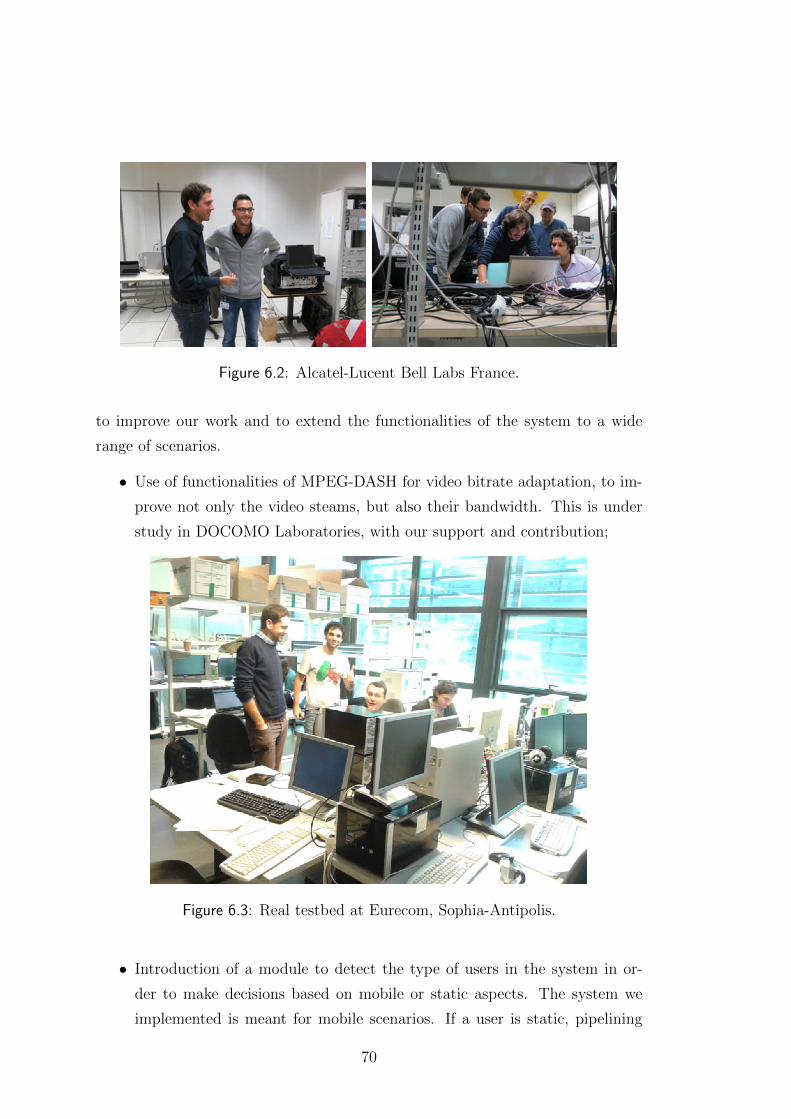
Figure 6.2: Alcatel-Lucent Bell Labs France.
to improve our work and to extend the functionalities of the system to a wide
range of scenarios.
• Use of functionalities of MPEG-DASH for video bitrate adaptation, to im-
prove not only the video steams, but also their bandwidth. This is under
study in DOCOMO Laboratories, with our support and contribution;
Figure 6.3: Real testbed at Eurecom, Sophia-Antipolis.
• Introduction of a module to detect the type of users in the system in or-
der to make decisions based on mobile or static aspects. The system we
implemented is meant for mobile scenarios. If a user is static, pipelining
70
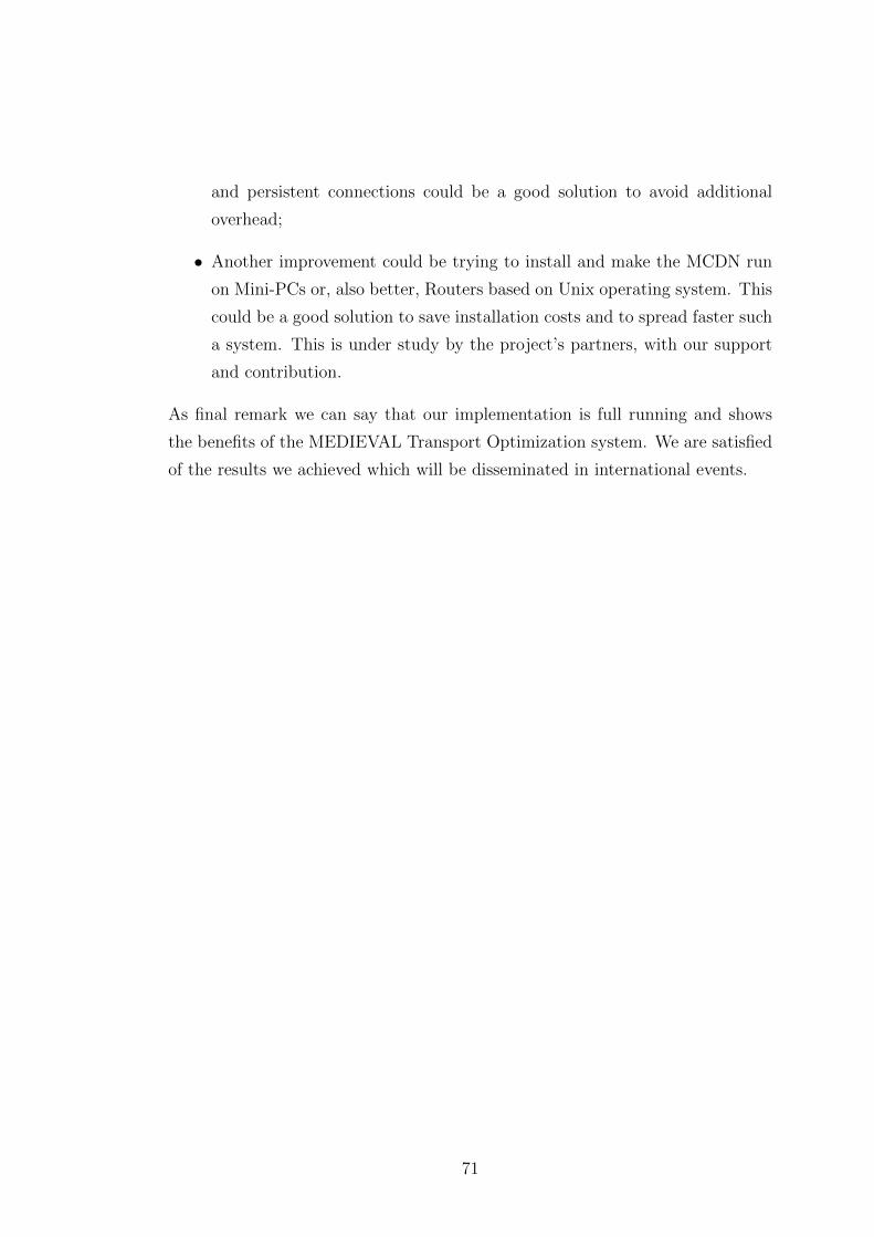
and persistent connections could be a good solution to avoid additional
overhead;
• Another improvement could be trying to install and make the MCDN run
on Mini-PCs or, also better, Routers based on Unix operating system. This
could be a good solution to save installation costs and to spread faster such
a system. This is under study by the project’s partners, with our support
and contribution.
As final remark we can say that our implementation is full running and shows
the benefits of the MEDIEVAL Transport Optimization system. We are satisfied
of the results we achieved which will be disseminated in international events.
71

72
Appendix A
Functional architecture: details
A.1 Video Services Control
The video service control (VSC) subsystem [24] is responsible for linking the ser-
vices and the underlying network delivery entities. It aims at enabling a reliable
video delivery over an evolved mobile network, which offers improved resources
utilisation and an enhanced user experience, by proposing a new cross-layer set
of interfaces from video service controls to video applications, to mobility, and
to transport optimisation. This subsystem also proposes a set of innovative ser-
vice controllers to support a new world of video applications, leveraged by the
social networking trend, hiding the service management issues from the multime-
dia applications, in order to allow new video-related services, with QoS support,
improving resource utilisation and application flexibility.
Last, the subsystem also provides reliable and adaptive content delivery in inher-
ently unreliable networks, maximising the users’ quality of experience, taking into
account the network dynamics as well as other potential factors, such as moneti-
sation schemes or user differentiation, for the variety of video-rich applications.
The video service control is mainly responsible for:
• Service provisioning which is further segmented into services, contents and
user attributes;
• Session management and network monitoring, which initiates service ses-
sions and provides ongoing measurements of the underlying networks con-
ditions;
73
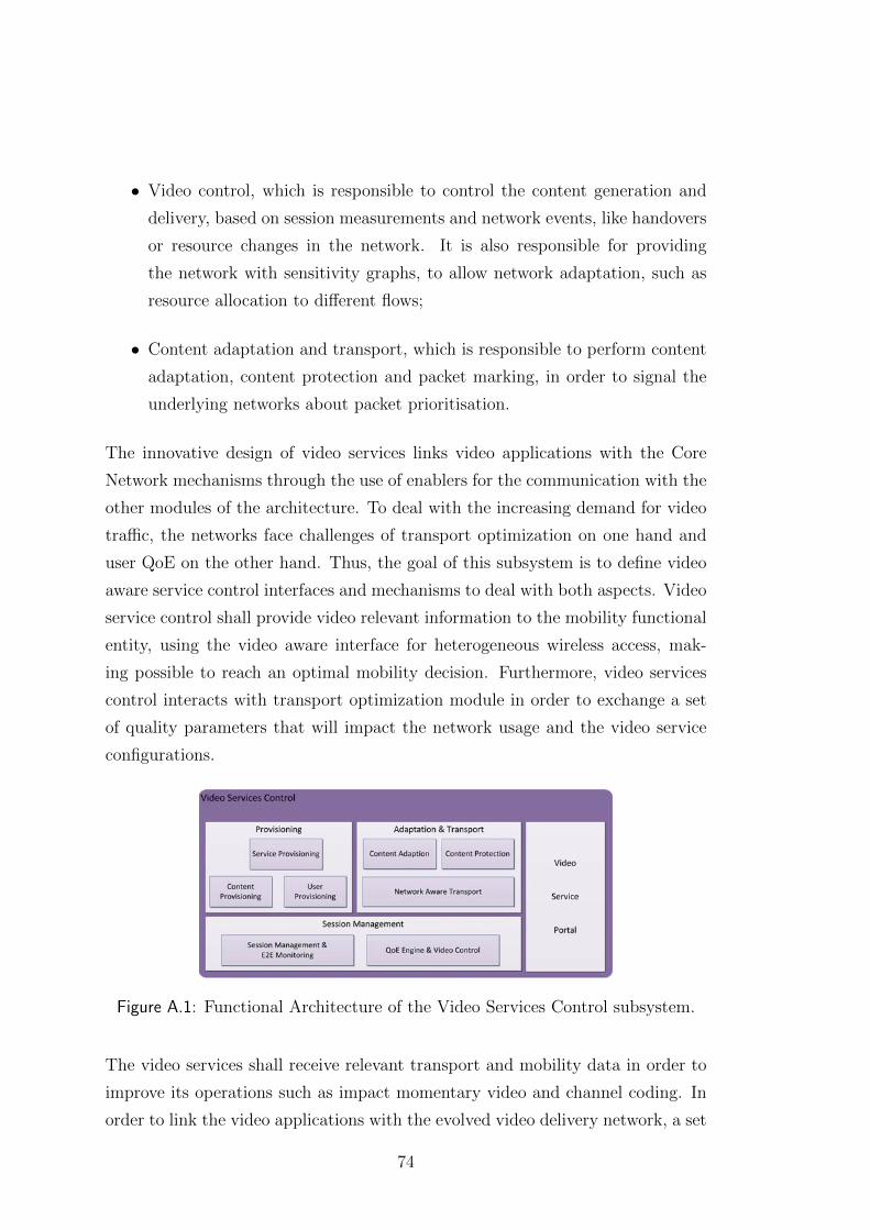
• Video control, which is responsible to control the content generation and
delivery, based on session measurements and network events, like handovers
or resource changes in the network. It is also responsible for providing
the network with sensitivity graphs, to allow network adaptation, such as
resource allocation to different flows;
• Content adaptation and transport, which is responsible to perform content
adaptation, content protection and packet marking, in order to signal the
underlying networks about packet prioritisation.
The innovative design of video services links video applications with the Core
Network mechanisms through the use of enablers for the communication with the
other modules of the architecture. To deal with the increasing demand for video
traffic, the networks face challenges of transport optimization on one hand and
user QoE on the other hand. Thus, the goal of this subsystem is to define video
aware service control interfaces and mechanisms to deal with both aspects. Video
service control shall provide video relevant information to the mobility functional
entity, using the video aware interface for heterogeneous wireless access, mak-
ing possible to reach an optimal mobility decision. Furthermore, video services
control interacts with transport optimization module in order to exchange a set
of quality parameters that will impact the network usage and the video service
configurations.
Figure A.1: Functional Architecture of the Video Services Control subsystem.
The video services shall receive relevant transport and mobility data in order to
improve its operations such as impact momentary video and channel coding. In
order to link the video applications with the evolved video delivery network, a set
74
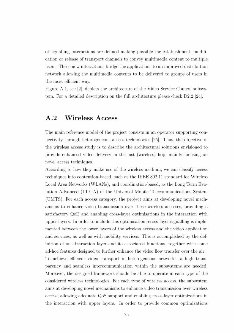
of signalling interactions are defined making possible the establishment, modifi-
cation or release of transport channels to convey multimedia content to multiple
users. These new interactions bridge the applications to an improved distribution
network allowing the multimedia contents to be delivered to groups of users in
the most efficient way.
Figure A.1, see [2], depicts the architecture of the Video Service Control subsys-
tem. For a detailed description on the full architecture please check D2.2 [24].
A.2 Wireless Access
The main reference model of the project consists in an operator supporting con-
nectivity through heterogeneous access technologies [25]. Thus, the objective of
the wireless access study is to describe the architectural solutions envisioned to
provide enhanced video delivery in the last (wireless) hop, mainly focusing on
novel access techniques.
According to how they make use of the wireless medium, we can classify access
techniques into contention-based, such as the IEEE 802.11 standard for Wireless
Local Area Networks (WLANs), and coordination-based, as the Long Term Evo-
lution Advanced (LTE-A) of the Universal Mobile Telecommunications System
(UMTS). For each access category, the project aims at developing novel mech-
anisms to enhance video transmission over these wireless accesses, providing a
satisfactory QoE and enabling cross-layer optimisations in the interaction with
upper layers. In order to include this optimisation, cross-layer signalling is imple-
mented between the lower layers of the wireless access and the video application
and services, as well as with mobility services. This is accomplished by the def-
inition of an abstraction layer and its associated functions, together with some
ad-hoc features designed to further enhance the video flow transfer over the air.
To achieve efficient video transport in heterogeneous networks, a high trans-
parency and seamless intercommunication within the subsystems are needed.
Moreover, the designed framework should be able to operate in each type of the
considered wireless technologies. For each type of wireless access, the subsystem
aims at developing novel mechanisms to enhance video transmission over wireless
access, allowing adequate QoS support and enabling cross-layer optimizations in
the interaction with upper layers. In order to provide common optimizations
75
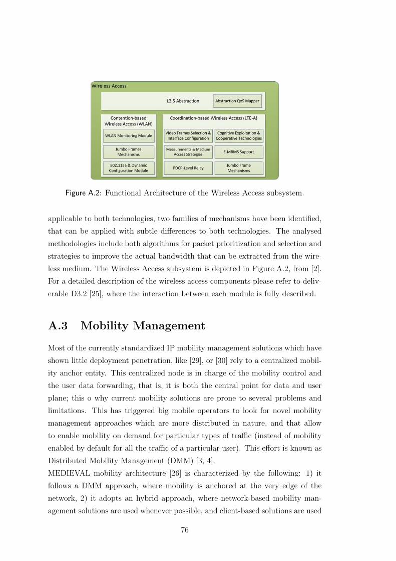
Figure A.2: Functional Architecture of the Wireless Access subsystem.
applicable to both technologies, two families of mechanisms have been identified,
that can be applied with subtle differences to both technologies. The analysed
methodologies include both algorithms for packet prioritization and selection and
strategies to improve the actual bandwidth that can be extracted from the wire-
less medium. The Wireless Access subsystem is depicted in Figure A.2, from [2].
For a detailed description of the wireless access components please refer to deliv-
erable D3.2 [25], where the interaction between each module is fully described.
A.3 Mobility Management
Most of the currently standardized IP mobility management solutions which have
shown little deployment penetration, like [29], or [30] rely to a centralized mobil-
ity anchor entity. This centralized node is in charge of the mobility control and
the user data forwarding, that is, it is both the central point for data and user
plane; this o why current mobility solutions are prone to several problems and
limitations. This has triggered big mobile operators to look for novel mobility
management approaches which are more distributed in nature, and that allow
to enable mobility on demand for particular types of traffic (instead of mobility
enabled by default for all the traffic of a particular user). This effort is known as
Distributed Mobility Management (DMM) [3, 4].
MEDIEVAL mobility architecture [26] is characterized by the following: 1) it
follows a DMM approach, where mobility is anchored at the very edge of the
network, 2) it adopts an hybrid approach, where network-based mobility man-
agement solutions are used whenever possible, and client-based solutions are used
76
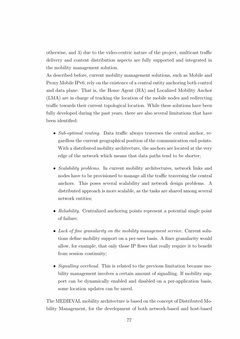
otherwise, and 3) due to the video-centric nature of the project, multicast traffic
delivery and content distribution aspects are fully supported and integrated in
the mobility management solution.
As described before, current mobility management solutions, such as Mobile and
Proxy Mobile IPv6, rely on the existence of a central entity anchoring both control
and data plane. That is, the Home Agent (HA) and Localized Mobility Anchor
(LMA) are in charge of tracking the location of the mobile nodes and redirecting
traffic towards their current topological location. While these solutions have been
fully developed during the past years, there are also several limitations that have
been identified:
• Sub-optimal routing. Data traffic always traverses the central anchor, re-
gardless the current geographical position of the communication end-points.
With a distributed mobility architecture, the anchors are located at the very
edge of the network which means that data paths tend to be shorter;
• Scalability problems. In current mobility architectures, network links and
nodes have to be provisioned to manage all the traffic traversing the central
anchors. This poses several scalability and network design problems. A
distributed approach is more scalable, as the tasks are shared among several
network entities;
• Reliability. Centralized anchoring points represent a potential single point
of failure;
• Lack of fine granularity on the mobility management service. Current solu-
tions define mobility support on a per-user basis. A finer granularity would
allow, for example, that only those IP flows that really require it to benefit
from session continuity;
• Signalling overhead. This is related to the previous limitation because mo-
bility management involves a certain amount of signalling. If mobility sup-
port can be dynamically enabled and disabled on a per-application basis,
some location updates can be saved.
The MEDIEVAL mobility architecture is based on the concept of Distributed Mo-
bility Management, for the development of both network-based and host-based
77
mobility management. The access network is organized in Localized Mobility Do-
mains (LMD) in which a network-based scheme is applied. Users are expected to
be most of the time roaming within a single LMD, but, for those cases where this
is not possible, a host-based DMM approach is followed. In order to integrate
both approaches, so a mobile node can simultaneously have sessions managed
by a network-based approach and a host-based approach, we introduce a novel
architectural element called Mobile Access Router (MAR). An MAR is a network
entity implementing all the functionalities of its counterparts in the standard
mobility protocols (MIPv6 and PMIPv6), so it is able to play the role of plain
access router, home agent, local mobility anchor and mobile access gateway on a
per-address basis.
Nevertheless, MEDIEVAL project poses new challenges in distributing video con-
tent with defined Quality of Experience (QoE) requirements. In order to be able
to always guarantee these requirements, users’ traffic might be redirected or of-
floaded looking for the best network and terminal conditions for video transmis-
sion.
The mobility subsystem is based on the Distributed Mobility Management con-
cept and enriched by its per-flow granularity awareness, which enables to provide
differentiated treatment to video data packets and to other traffic. The archi-
tecture of the subsystem is shown in Figure A.3, from [2], and it is composed of
three components: Connection Manager (CM), Flow Manager (FM) and Mobil-
ity Engine (ME). We next summarize the main features of these components; for
additional details, please refer to D4.1 [26] and D4.2 [27].
Figure A.3: Functional Architecture of the Mobility Management subsystem.
78
Mobile Engine. The mobility engine (ME) is the main component of the mo-
bility subsystem. It basically takes care of two critical functionalities: 1) Han-
dover control and 2) IP address continuity. The handover control part consists in
performing the operations required for achieving a Make-Before-Break handover,
namely: signal power sensing, best Point of Attachment (PoA) selection, resource
preparation, detachment/attachment detection, link establishment, IP configura-
tion and resource release. This phase is assisted and controlled by means of
IEEE 802.21 infrastructure and Neighbour Discovery signalling. While this first
functionality has to be performed in any change of PoA, there are also certain
handovers in which the continuity of some IP addresses need to be maintained.
In those cases, the second functionality (IP address continuity) is also required,
and basically consists in triggering the MEDIEVAL IP flow mobility procedures,
namely sending the required mobility messages and tunnel management and rout-
ing operations.
The mobility engine component is composed of the following three modules:
• Unicast Mobility Engine (UME). It is the module in charge of perform-
ing the unicast IP mobility operations and signalling following the DMM
paradigm. This module is implemented both on the network and client side;
• Multicast Mobility Engine (MUME). It manages the IP mobility support
for the multicast flows. This module is implemented only on the network
side;
• NEMO Mobility Engine (NME). This module is in charge of extending the
MEDIEVAL access network so it also comprise mobile platforms, not only
fixed ones. That means that an MN will not only be able to roam between
fixed attachment points to the infrastructure, but also between fixed and
mobile ones.
Flow Manager. The Flow Manager (FM) resides in the MAR. The most im-
portant function is the management of data flows. The mobility management is,
in fact, applied on a per-flow basis. The FM is the main path of communication
between the Mobility Subsystem and external subsystems such as Wireless Ac-
cess, Transport Optimization and Video Service Control, playing therefore a key
role in the whole architecture.
79
The main focus of the FM within the mobility framework is to keep track of data
flows that traverse it and manage the data flows to provide the mobile user with
the best possible service. To this purpose the FM leverages on two advantages:
1) the tight relationship it has with the remaining MEDIEVAL mobility compo-
nents; 2) the FM’s central position on the MAR where it has a good perspective
of both the access network as well as the infrastructure near the access, enabling
it to gather information from both perspectives to provide better decisions.
Connection Manager. The Connection Manager (CM) resides in the client
and is responsible to manage all connectivity actions required in the terminal side.
The CM is a Media Independent Handover (MIH) user that interacts with the
wireless access networks using 802.21 primitives in order to implement mobility,
routing and flow handling.
The CM implements access network policies, selecting the preferred access inter-
face to use or splitting the traffic along the multiple access networks available,
when the terminal is able to use them simultaneously. These policies can be
provisioned on the CM by multiple sources, namely CM GUIs, applications and
operators.
80
Bibliography
[1] MEDIEVAL (MultiMEDia transport for mobIlE Video AppLications),
2010, [Online]. Available: http://www.ict-medieval.eu/
[2] MEDIEVAL, Deliverable D1.1, Preliminary architecture design.
[3] T. Melia, F. Giust, R. Manfrin, A. de la Oliva, C. J. Bernardos, and M.
Wetterwald, IEEE 802.21 and Proxy Mobile IPv6: A Network Controlled
Mobility Solution, Future Network and Mobile Summit 2011 Conference
Proceedings, June 2011.
[4] T. Melia, C. J. Bernardos, A. de la Oliva, F. Giust, and M. Calderon, IP
Flow Mobility in PMIPv6 Based Networks: Solution Design and
Experimental Evaluation, Wireless Personal Communication, vol. Special
issue, 2011.
[5] MEDIEVAL, Deliverable D5.2, Final Specification for transport
optimization components & interfaces.
[6] D. Munaretto, T. Melia, S. Randriamasy and M. Zorzi, Online path
selection for video delivery over cellular networks, IEEE Globecom
(QoEMC), December 2012.
[7] MEDIEVAL, Deliverable D5.3, Advanced CDN mechanisms for video
streaming.
[8] MEDIEVAL, Deliverable D5.1, Transport Optimization: initial architecture.
[9] tproxy project, July 2008. [Online]. Available:
http://www.balabit.com/support/community/products/tproxy
81
[10] netfilter.org project, November 1999. [Online]. Available:
http://www.netfilter.org/
[11] C. Muller and C. Timmerer, A Test-Bed for the Dynamic Adaptive
Streaming over HTTP featuring Session Mobility, In Proceedings of the
ACM Multimedia Systems Conference 2011, San Jose, California, February
23-25, 2011.
[12] I. Sodagar, The MPEG-DASH Standard for Multimedia Streaming Over the
Internet, IEEE Multimedia, IEEE MultiMedia, October-December 2011,
pp. 62-67.
[13] T. Stockhammer, I. Sodagar, MPEG DASH: The Enabler Standard for
Video Deliver Over The Open Internet, IBC Conference 2011, Sept 2011.
[14] S. Lederer, C. Muller, B. Rainer, C. Timmerer, and H. Hellwagner,
Adaptive Streaming over Content Centric Networks in Mobile Networks
using Multiple Links, In Proceedings of the IEEE International Workshop
on Immersive & Interactive Multimedia Communications over the Future
Internet, Budapest, Hungary, June, 2013.
[15] I. Sodagar and H. Pyle, Reinventing multimedia delivery with
MPEG-DASH, SPIE Applications of Digital Image Processing XXXIV,
Sept 2011.
[16] T. Stockhammer, Dynamic Adaptive Streaming over HTTP-Design
Priciples and Standards, MMSys 11: Proceedings of the second annual
ACM conference on Multimedia systems New York, ACM Press, February
2011, S. 133-144.
[17] squid-cache.org: Optimising Web Delivery, 1990, [Online]. Available:
http://www.squid-cache.org
[18] Saini K., Squid Proxy Server 3.1 Beginner’s Guide, Packt Publishing
Limited, 2011.
[19] Apache HTTP Server Project, February 1995, [Online]. Available:
http://httpd.apache.org
82
[20] S. Cozens and P. Wainwright, Beginning Perl (Programmer to
Programmer), Wrox Press, May 2000.
[21] C. Muller and C. Timmerer, A VLC Media Player Plugin enabling
Dynamic Adaptive Streaming over HTTP, In Proceedings of the ACM
Multimedia 2011 , Scottsdale, Arizona, November 28, 2011.
[22] R. Fielding, J. Gettys, J. Mogul, H. Frystyk, L. Masinter, P. Leach and T.
Berners-Lee, Hypertext Transfer Protocol – HTTP/1.1, RFC 2616, June
1999. [Online]. Available: http://tools.ietf.org/html/rfc2616
[23] UNI Klagenfurt, Institute of Information Technology - ITEC. [Online].
Available: http://www.uni-klu.ac.at/tewi/inf/itec/
[24] MEDIEVAL, Deliverable D2.2, Final Specification for video service control.
[25] MEDIEVAL, Deliverable D3.2, Final Specifications for the Wireless Access
functions and interfaces.
[26] MEDIEVAL, Deliverable D4.1, Light IP Mobility architecture for Video
Services: initial architecture.
[27] MEDIEVAL, Deliverable D4.2, IP Multicast Mobility Solutions for Video
Services.
[28] ALTO: IETF application-layer traffic optimization (active WG). [Online].
Available: http://tools.ietf.org/wg/alto/
[29] D. Johnson, C. Perkins and J. Arkko, Mobility Support in IPv6, RFC 3775,
June 2004. [Online]. Available: http://tools.ietf.org/html/rfc3775
[30] S. Gundavelli, K. Leung, V. Devarapalli, K. Chowdhury, and B. Patil,
Proxy Mobile IPv6, RFC 5213, August 2008. [Online]. Available:
http://tools.ietf.org/html/rfc5213
83


Acknowledgements
There are many people I would like to thank you for the opportunity and the
help given me in this course of study.
First of all I would like to thank Prof. Michele Zorzi who gave me the chance to
experience this unforgettable thesis work. Of course, thanks to the efforts made
by Daniele, and initially also Davide, who advised me very well and supported
me all of the time!
Then, I would like to thank all colleagues of DOCOMO Euro-Labs, Munich,
for welcoming me in the best of ways. In particular, the ’coffee-group’, David,
Wolfgang, Xueli, Joan, Bo, Sandra, led by Gerald and Dirk, extraordinary people
who gave me gorgeous opportunities for growth, professional and not. In those 5
months I learned more than in the previous 5 years.
A special thanks also to Telemaco, Carlos and Fabio, who helped me during the
first days of implementation and integration (and not only). Thank you very
much for your patience! Thank you all!
Alberto Desidera