MERKE PASO lehnt jede Haftung für Schäden an Personen und / … · - PMS2000 System -1...
24
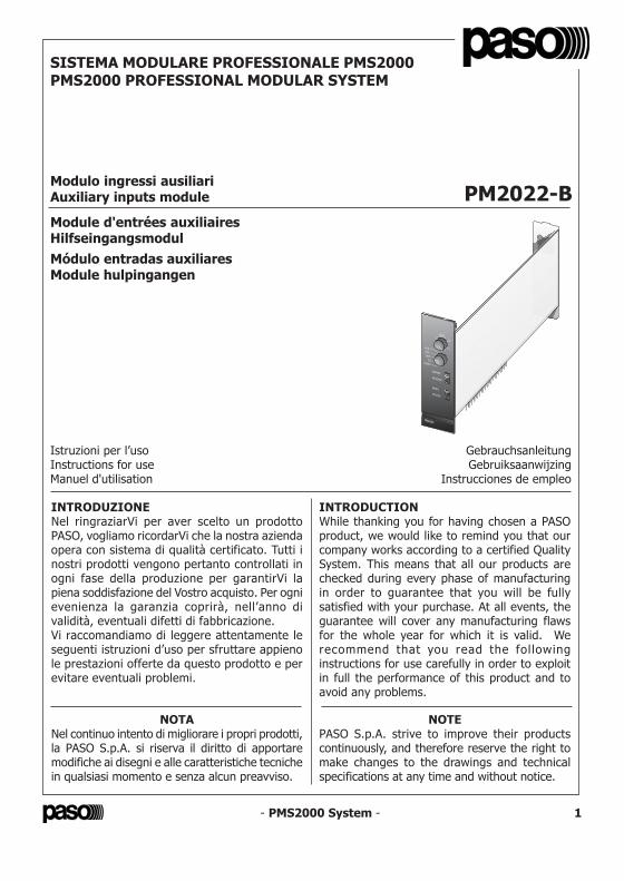
1 - PMS2000 System - INTRODUZIONE Nel ringraziarVi per aver scelto un prodotto PASO, vogliamo ricordarVi che la nostra azienda opera con sistema di qualità certificato. Tutti i nostri prodotti vengono pertanto controllati in ogni fase della produzione per garantirVi la piena soddisfazione del Vostro acquisto. Per ogni evenienza la garanzia coprirà, nell’anno di validità, eventuali difetti di fabbricazione. Vi raccomandiamo di leggere attentamente le seguenti istruzioni d’uso per sfruttare appieno le prestazioni offerte da questo prodotto e per evitare eventuali problemi. INTRODUCTION While thanking you for having chosen a PASO product, we would like to remind you that our company works according to a certified Quality System. This means that all our products are checked during every phase of manufacturing in order to guarantee that you will be fully satisfied with your purchase. At all events, the guarantee will cover any manufacturing flaws for the whole year for which it is valid. We recommend that you read the following instructions for use carefully in order to exploit in full the performance of this product and to avoid any problems. NOTA Nel continuo intento di migliorare i propri prodotti, la PASO S.p.A. si riserva il diritto di apportare modifiche ai disegni e alle caratteristiche tecniche in qualsiasi momento e senza alcun preavviso. NOTE PASO S.p.A. strive to improve their products continuously, and therefore reserve the right to make changes to the drawings and technical specifications at any time and without notice. Istruzioni per l’uso Instructions for use Manuel d'utilisation Gebrauchsanleitung Gebruiksaanwijzing Instrucciones de empleo SISTEMA MODULARE PROFESSIONALE PMS2000 PMS2000 PROFESSIONAL MODULAR SYSTEM Modulo ingressi ausiliari Auxiliary inputs module PM2022-B Module d'entrées auxiliaires Hilfseingangsmodul Módulo entradas auxiliares Module hulpingangen
Transcript of MERKE PASO lehnt jede Haftung für Schäden an Personen und / … · - PMS2000 System -1...
1 - PMS2000 System -
INTRODUZIONENel ringraziarVi per aver scelto un prodottoPASO, vogliamo ricordarVi che la nostra aziendaopera con sistema di qualità certificato. Tutti inostri prodotti vengono pertanto controllati inogni fase della produzione per garantirVi lapiena soddisfazione del Vostro acquisto. Per ognievenienza la garanzia coprirà, nell’anno divalidità, eventuali difetti di fabbricazione.Vi raccomandiamo di leggere attentamente leseguenti istruzioni d’uso per sfruttare appienole prestazioni offerte da questo prodotto e perevitare eventuali problemi.
INTRODUCTIONWhile thanking you for having chosen a PASOproduct, we would like to remind you that ourcompany works according to a certified QualitySystem. This means that all our products arechecked during every phase of manufacturingin order to guarantee that you will be fullysatisfied with your purchase. At all events, theguarantee will cover any manufacturing flawsfor the whole year for which it is valid. Werecommend that you read the fol lowinginstructions for use carefully in order to exploitin full the performance of this product and toavoid any problems.
NOTANel continuo intento di migliorare i propri prodotti,la PASO S.p.A. si riserva il diritto di apportaremodifiche ai disegni e alle caratteristiche tecnichein qualsiasi momento e senza alcun preavviso.
NOTEPASO S.p.A. strive to improve their productscontinuously, and therefore reserve the right tomake changes to the drawings and technicalspecifications at any time and without notice.
Istruzioni per l’usoInstructions for useManuel d'utilisation
GebrauchsanleitungGebruiksaanwijzing
Instrucciones de empleo
SISTEMA MODULARE PROFESSIONALE PMS2000PMS2000 PROFESSIONAL MODULAR SYSTEM
Modulo ingressi ausiliariAuxiliary inputs module PM2022-BModule d'entrées auxiliairesHilfseingangsmodulMódulo entradas auxiliaresModule hulpingangen
- PMS2000 System -
Ref. 11/496-B PM2022-B
24
Via Mecenate, 90 - 20138 MILANO - ITALIATEL. +39-02-580 77 1 (15 linee r.a.)
FAX +39-02-580 77 277http://www.paso.it
Printed in Italy - 01/05 - 0.1K - 11/496-B
S.p.A
NOTALa PASO declina ogni responsabilità per danni a cose e/o persone derivanti dall'uso noncorretto dell'apparecchio o da procedure non rispondenti a quanto riportato sul presentelibretto.
NOTEPASO will not accept any liability for damage to property and/or persons arising out ofincorrect use of the equipment or of procedures that do not comply with the instructionsprovided in this booklet.
NOTEPASO décline toute responsabilité en cas de dommages matériels et/ou physiques provoquéspar l'utilisation impropre de l'appareil ou encore par des opérations ou des interventions nerespectant pas les instructions figurant dans la présente notice.
MERKEPASO lehnt jede Haftung für Schäden an Personen und / oder Gegenständen ab, die durchunzweckmäßige Verwendung oder Vorgehen entstehen, die nicht den Anweisungen diesesHandbuches entsprechen.
OPMERKINGPASO kan niet aansprakelijk worden gesteld voor schade aan voorwerpen en/of persoonlijkletsel die het gevolg zijn van een onjuist gebruik van het apparaat of van procedures die nietovereenkomen met de voorschriften uit deze handleiding.
NOTALa PASO rehusa cualquier responsabilidad ante daños a cosas y/o personas causados por unautilización no correcta del aparato o por operaciones no conformes a cuanto indicado en estefolleto.
- PMS2000 System -2
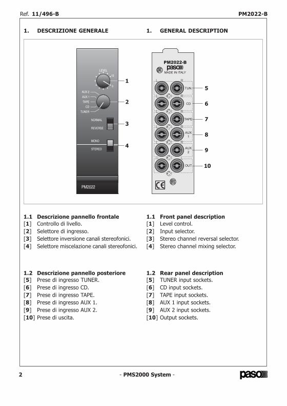
1.1 Descrizione pannello frontale[1] Controllo di livello.[2] Selettore di ingresso.[3] Selettore inversione canali stereofonici.[4] Selettore miscelazione canali stereofonici.
1.1 Front panel description[1] Level control.[2] Input selector.[3] Stereo channel reversal selector.[4] Stereo channel mixing selector.
1.2 Descrizione pannello posteriore[5] Prese di ingresso TUNER.[6] Prese di ingresso CD.[7] Prese di ingresso TAPE.[8] Prese di ingresso AUX 1.[9] Prese di ingresso AUX 2.[10] Prese di uscita.
1.2 Rear panel description[5] TUNER input sockets.[6] CD input sockets.[7] TAPE input sockets.[8] AUX 1 input sockets.[9] AUX 2 input sockets.[10] Output sockets.
1. GENERAL DESCRIPTION1. DESCRIZIONE GENERALE
- PMS2000 System - 23
Ref. 11/496-B PM2022-B Ref. 11/496-B PM2022-B
- PMS2000 System - 3
2. CONSIDERAZIONI GENERALIIl modulo ingressi ausiliari permette di collegareal sistema sorgenti audio musicali, sia di tipostereofonico che di t ipo monofonico,caratterizzate da un alto livello di uscita.É possibile selezionare, tramite un commutatorerotativo, fino a cinque differenti sorgentiapplicate ai relativi ingressi.Questo modulo dispone di:• regolazione di sensibilità per l'ingresso
‘TUNER’;• commutatore ‘STEREO/MONO’;• commutatore per l'inversione dei canali
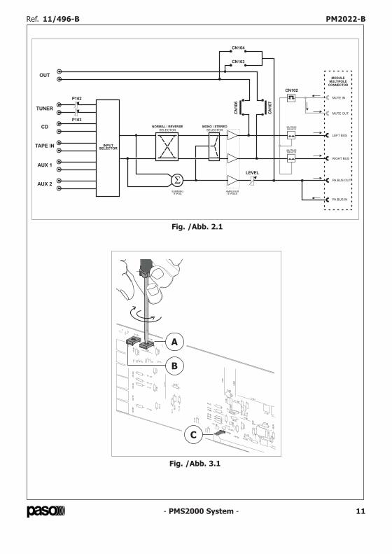
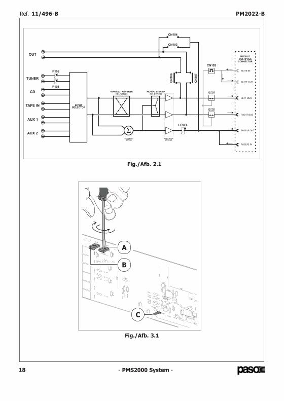
‘SINISTRO/DESTRO’;• controllo di livello del segnale ‘PA’.In fig. 2.1 è riportato lo schema a blocchi delmodulo.
2. GENERAL CONSIDERATIONSThe auxiliary input module can be used to connectmusic audio sources, both stereo and mono,featuring high output levels to the system.It is possible to select up to five different sourcesapplied to the related inputs.They are selected by means of a rotary switch.
This module has the following:• sensitivity adjustment for the ‘TUNER’
input;• ‘STEREO/MONO’ switch;• switch for reversing the ‘LEFT/RIGHT’
channels;• ‘PA’ signal level control.Figure 2.1 shows the block diagram of themodule.
3. IMPOSTAZIONI DI FUNZIONAMENTO3.1 Sensibilità ingresso tunerLa sensibilità di ognuno dei due canali (canalesinistro e canale destro) dell'ingresso ‘TUNER’può essere adattata con precisione al livello delsegnale di uscita della sorgente ad esso applicata.
Per regolare la sensibilità del canale destrooccorrerà agire, per mezzo di piccolo giravite alame piatta, sul trimmer P103 (particolare [A]di fig. 3.1); ruotando il cursore del trimmer insenso orario la sensibilità aumenta, ruotandoloin senso antiorario la sensibilità diminuisce.
Per regolare la sensibilità del canale sinistrooccorrerà agire sul trimmer P102 (particolare[B] di fig. 3.1) analogamente a quanto descrittoper il canale destro.
Effettuando la regolazione della sensibilitàoccorrerà prestare particolare cura affinché ilbilanciamento tra i due canali risulti corretto(situazione verificabile, all'occorrenza, all'uscitadiretta del modulo).
3. OPERATIONAL SETTINGS3.1 Tuner input sensitivityThe sensitivity of each of the two channels (leftchannel and right channel) of the ‘TUNER’ inputcan be adapted precisely to the level of theoutput signal from the source applied to it.
To adjust the sensitivity of the right-handchannel, it is necessary to turn trimmer P103(detail [A] in Figure 3.1) using a small flat-bladed screwdriver. If the cursor of the trimmeris turned in a clockwise direction, the sensitivitywill increase. If it is turned in an anti-clockwisedirection the sensitivity will decrease.
To adjust the sensitivity of the left-hand channel,it is necessary to turn trimmer P102 (detail [B]in Figure 3.1), in a manner similar to thatdescribed for the right-hand channel.
When adjusting the sensitivity, special attentionshould be paid to achieving the correct balancebetween the two channels (this can be checked,if required, on the direct output from themodule).
- PMS2000 System -22
7. CARACTERÍSTICAS TÉCNICAS 7. TECHNISCHE KENMERKEN
Entradas seleccionables 5 Ingangen die geselecteerdkunnen worden
Sensibilidad / impedancia entrada TUNER (regulable) 200 mV ÷ 4 V / 20 kΩ Gevoeligheid / impedantie
TUNER-ingang (regelbaar)
Sensibilidad / impedanciaentrada AUX 1 200 mV / 47 kΩ Gevoeligheid / impedantie
AUX 1 - ingang
Sensibilidad / impedancia entrada AUX 2 950 mV / 47 kΩ Gevoeligheid / impedantie
AUX 2 - ingang
Sensibilidad / impedancia entrada CD 450 mV / 22 kΩ Gevoeligheid / impedantie
CD-ingang
Sensibilidad / impedancia entrada TAPE 200 mV / 47 kΩ Gevoeligheid / impedantie
TAPE-ingang
Relación señal / ruido > 85 dB Verhouding signaal / ruis
Relación señal / ruido(pesado "A") > 88 dBA Verhouding signaal / ruis
(gewogen "A")
Nivel / impedanciasalida módulo 650 mV / 1 kΩ Niveau / impedantie
uitgang module
Atenuación de precedencia > 70 dB Verzwakking door voorrang
Separación entre loscanales (10 kHz) > 60 dB Scheiding tussen de
kanalen (10 kHz)
Diafonía entre las entradas (10 kHz) > 70 dB Geluidsoverspraak tussen deingangen (10 kHz)
Ancho módulo 38 mm Breedte module
Consumo24 V / 0 mA
+15 V / 10 mA-15 V / 10 mA
Opname
Ref. 11/496-B PM2022-B Ref. 11/496-B PM2022-B

- PMS2000 System -4
Fig. 2.1
A
B
C
Fig. 3.1
- PMS2000 System - 21
6. AJUSTES Y USOLas señales aplicadas en las tomas ‘L’ y ‘R’ de laentrada seleccionada, después de haber sidopreamplificadas, son enviadas a las tomas desalida ‘OUT’ y al bus de mezcla estereofónico(línea derecha y línea izquierda).Estas señales, además, son mezcladas yenviadas, tras ser reguladas en amplitud(mediante el mando ‘LEVEL’), al bus de mezclamonofónico (bus PA).
6.1 Selector de entradaPermite seleccionar una de las cinco entradasdel módulo.
6.2 Selector NORMAL/REVERSEEste selector permite invertir entre ellos los doscanales estereofónicos.Este control puede ser de gran utilidad durantela puesta a punto de la instalación.
6.3 Selector MONO/STEREOEste selector, cuando está en la posición ‘MONO’,determina la mezcla, entre ellos, de los doscanales estereofónicos.
6.4 Control de nivelCon el mando ‘LEVEL’ [1] es posible ajustar laamplitud de la señal enviada al bus de mezcla PA,correspondiente a la entrada seleccionada.
6. INSTELLINGEN EN GEBRUIKDe signalen die verbonden zijn met deaansluitingen ‘L’ en ‘R’ van de geselecteerdeingang worden, na te zijn voorversterkt, naar deuitgangen ‘OUT’ en naar de stereo mengbus(rechter- en linkerlijn) gestuurd.Deze signalen worden bovendien gemengd en,na het instellen van de sterkte met behulp vande ‘LEVEL’ regelaar, naar de mono mengbus(PA-bus) gestuurd.
6.1 IngangskeuzeschakelaarHiermee kunt u één van de vijf ingangen van demodule selecteren.
6.2 Keuzeschakelaar NORMAL/REVERSEMet deze keuzeschakelaar kunt u de twee stereokanalen onderling omdraaien.Dit kan handig zijn bij het aanleggen van deinstallatie.
6.3 Keuzeschakelaar MONO/STEREOWanneer deze keuzeschakelaar op de stand‘MONO’ staat, worden de twee stereo kanalenmet elkaar gemengd.
6.4 NiveauregelaarMet de regelaar ‘LEVEL’ [1] kan de sterkte vanhet naar de mengbus PA gestuurde signaalgeregeld worden.
Ref. 11/496-B PM2022-B Ref. 11/496-B PM2022-B
LEVEL
NORMAL / REVERSE
SELECTOR
TUNER
CD
TAPE IN
AUX 1
AUX 2
OUT
MONO / STEREO
SELECTOR
MUTINGDEVICE
MUTINGDEVICE
SUMMINGSTAGE
AMPLIFIERSTAGES
MUTE IN
PA BUS IN
PA BUS OUT
LEFT BUS
RIGHT BUS
MUTE OUT
MODULE
MULTIPOLE
CONNECTOR
P102
CN102
P103
INPUTSELECTOR
CN104
CN103
CN
106
CN
107
- PMS2000 System - 5
3.2 Ammutolimento da linea di mutingQuando viene rilevata una condizione diprecedenza sull'apposito terminale (MUTE IN)del connettore multivia del modulo vengonoammutoliti (impostazione di default) i segnaliinviati al bus di miscelazione stereofonico(bus del canale sinistro e bus del canale destro).Per disabilitare questa funzione è necessariorimuovere il ponticello cortocircuitante inseritosui terminali del connettore CN102 (fig. 2.1).
NOTALa linea di muting entrante viene riportata,indipendentemente dalla presenza o meno delponticello sopracitato, al terminale ‘MUTE OUT’del connettore multivia ed inviata al moduloimmediatamente successivo (linea di mutinguscente).
3.2 Muting via the muting lineWhen a condition of precedence is detected onthe appropriate terminal (MUTE IN) of themulti-way connector of the module, the signalssent to the stereo mixing bus (bus of the leftchannel and bus of the right channel) are muted(default setting).To disable this function, it is necessary to removethe short-c ircui t ing jumper inserted onconnector CN102 terminals (Figure 2.1).
NOTERegardless of the presence or otherwise of thejumper referred to above, the incoming mutingline is led to the ‘MUTE OUT’ terminal of themulti-way connector and sent to the next modulealong (outgoing muting line).
4. INSTALLAZIONEIl modulo doppio ingresso deve essere installatonel cestello PMS2002-B seguendo le istruzionidi montaggio allegate a quest'ultimo.Si rammenta che la sua posizione, rispetto aglialtri moduli d'ingresso installati nel sistema, hainfluenza sui livelli di priorità.Più precisamente: affinché i segnali dellesorgenti musicali possano essere ammutoliti daimoduli “doppio ingresso” (o da moduli chedispongano degl i apposit i contatt i perl'attivazione della condizione di precedenza), ilmodulo ingresso ausiliari deve essere installatoalla destra di questi ultimi; in linea generale, unmodulo doppio ingresso non può ammutolire isegnali dei moduli installati alla sua sinistra.
NOTAAffinché possano essere ammutoliti anche isegnali applicati al bus stereofonico, il ponticellocortocircuitante deve essere lasciato inserito suiterminali del connettore CN102 (vedi par. 3.2).
4. INSTALLATIONThe double-input module has to be installed inthe PMS2002-B card cage following themounting instructions supplied with the cardcage. It must be remembered that its position inrespect of the other input modules installed inthe system affects the priority levels.Specifically, in order to enable the signals of themusic sources to be muted by the “double-inputmodules” (or by modules that have theappropriate contacts for activating theprecedence conditions), the auxiliary inputmodule must be installed to the right of thesemodules. Generally speaking, a double-inputmodule cannot mute the signals of the modulesinstalled to its left.
NOTEIn order to be able to mute the signals appliedto the stereo bus as well, the short-circuitingjumper must be left installed on the terminals ofconnector CN102 (see point 3.2).
- PMS2000 System -20
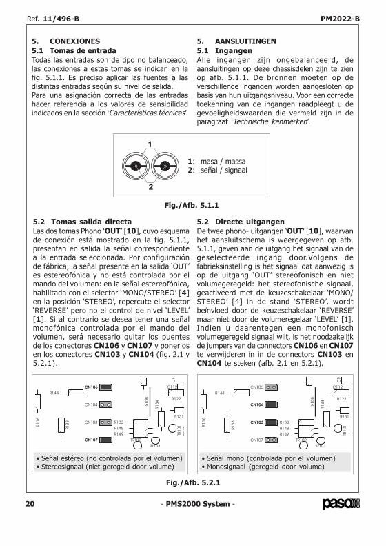
5. CONEXIONES5.1 Tomas de entradaTodas las entradas son de tipo no balanceado,las conexiones a estas tomas se indican en lafig. 5.1.1. Es preciso aplicar las fuentes a lasdistintas entradas según su nivel de salida.Para una asignación correcta de las entradashacer referencia a los valores de sensibilidadindicados en la sección ‘Características técnicas’.
5. AANSLUITINGEN5.1 IngangenAlle ingangen zijn ongebalanceerd, deaansluitingen op deze chassisdelen zijn te zienop afb. 5.1.1. De bronnen moeten op deverschillende ingangen worden aangesloten opbasis van hun uitgangsniveau. Voor een correctetoekenning van de ingangen raadpleegt u degevoeligheidswaarden die vermeld zijn in deparagraaf ‘Technische kenmerken’.
5.2 Tomas salida directaLas dos tomas Phono ‘OUT’ [10], cuyo esquemade conexión está mostrado en la fig. 5.1.1,presentan en salida la señal correspondientea la entrada seleccionada. Por configuraciónde fábrica, la señal presente en la salida ‘OUT’es estereofónica y no está controlada por elmando del volumen: en la señal estereofónica,habilitada con el selector ‘MONO/STEREO’ [4]en la posición ‘STEREO’, repercute el selector‘REVERSE’ pero no el control de nivel ‘LEVEL’[1]. Si al contrario se desea tener una señalmonofónica controlada por el mando delvolumen, será necesario quitar los puentesde los conectores CN106 y CN107 y ponerlosen los conectores CN103 y CN104 (fig. 2.1 y5.2.1).
5.2 Directe uitgangenDe twee phono- uitgangen ‘OUT’ [10], waarvanhet aansluitschema is weergegeven op afb.5.1.1, geven aan de uitgang het signaal van degeselecteerde ingang door.Volgens defabrieksinstelling is het signaal dat aanwezig isop de uitgang ‘OUT’ stereofonisch en nietvolumegeregeld: het stereofonische signaal,geactiveerd met de keuzeschakelaar ‘MONO/STEREO’ [4] in de stand ‘STEREO’, wordtbeïnvloed door de keuzeschakelaar ‘REVERSE’maar niet door de volumeregelaar ‘LEVEL’ [1].Indien u daarentegen een monofonischvolumegeregeld signaal wilt, is het noodzakelijkde jumpers van de connectors CN106 en CN107te verwijderen in in de connectors CN103 enCN104 te steken (afb. 2.1 en 5.2.1).
Fig./Afb. 5.1.1
1
2
1: masa / massa2: señal / signaal
Ref. 11/496-B PM2022-B Ref. 11/496-B PM2022-B
Fig./Afb. 5.2.1
C1
R1
16
R144
R122
TR102
C 02
A
X1
08
C112
R1
47
TR103
R1
38 CN103
CN106
CN107
CN104
R149
R1
34
R148
TR1
01
R133
R131
• Señal estéreo (no controlada por el volumen)• Stereosignaal (niet geregeld door volume)
C1
0
R1
16
R144
R122
TR102
C 02
A
X1
08
C112
R1
47
TR103
R1
38 CN103
CN106
CN107
CN104
R149
R1
34
R148
TR1
01
R133
R131
• Señal mono (controlada por el volumen)• Monosignaal (geregeld door volume)
- PMS2000 System -6
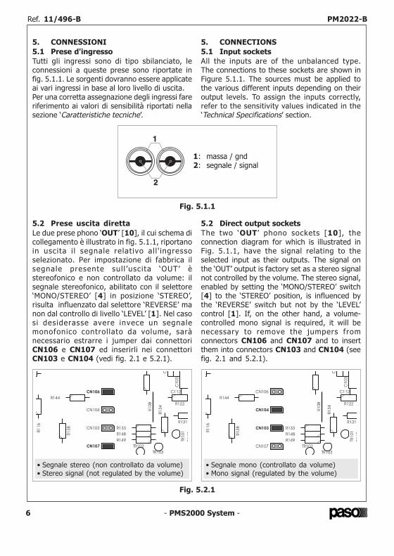
5. CONNESSIONI5.1 Prese d'ingressoTutti gli ingressi sono di tipo sbilanciato, leconnessioni a queste prese sono riportate infig. 5.1.1. Le sorgenti dovranno essere applicateai vari ingressi in base al loro livello di uscita.Per una corretta assegnazione degli ingressi fareriferimento ai valori di sensibilità riportati nellasezione ‘Caratteristiche tecniche’.
5. CONNECTIONS5.1 Input socketsAll the inputs are of the unbalanced type.The connections to these sockets are shown inFigure 5.1.1. The sources must be applied tothe various different inputs depending on theiroutput levels. To assign the inputs correctly,refer to the sensitivity values indicated in the‘Technical Specifications’ section.
5.2 Prese uscita direttaLe due prese phono ‘OUT’ [10], il cui schema dicollegamento è illustrato in fig. 5.1.1, riportanoin uscita i l segnale relativo al l ' ingressoselezionato. Per impostazione di fabbrica ilsegnale presente sul l ’uscita ‘OUT’ èstereofonico e non controllato da volume: ilsegnale stereofonico, abilitato con il selettore‘MONO/STEREO’ [4] in posizione ‘STEREO’,risulta influenzato dal selettore ‘REVERSE’ manon dal controllo di livello ‘LEVEL’ [1]. Nel casosi desiderasse avere invece un segnalemonofonico control lato da volume, sarànecessario estrarre i jumper dai connettoriCN106 e CN107 ed inserirli nei connettoriCN103 e CN104 (vedi fig. 2.1 e 5.2.1).
5.2 Direct output socketsThe two ‘OUT ’ phono sockets [10], theconnection diagram for which is illustrated inFig. 5.1.1, have the signal relating to theselected input as their outputs. The signal onthe ‘OUT’ output is factory set as a stereo signalnot controlled by the volume. The stereo signal,enabled by setting the ‘MONO/STEREO’ switch[4] to the ‘STEREO’ position, is influenced bythe ‘REVERSE’ switch but not by the ‘LEVEL’control [1]. If, on the other hand, a volume-controlled mono signal is required, it will benecessary to remove the jumpers fromconnectors CN106 and CN107 and to insertthem into connectors CN103 and CN104 (seefig. 2.1 and 5.2.1).
Fig. 5.1.1
1
2
1: massa / gnd2: segnale / signal
- PMS2000 System - 19
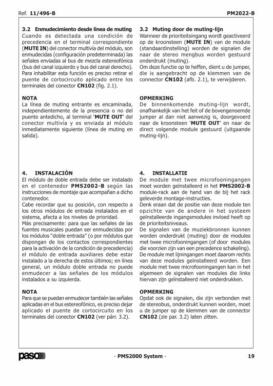
3.2 Enmudecimiento desde línea de mutingCuando es detectada una condición deprecedencia en el terminal correspondiente(MUTE IN) del conector multivía del módulo, sonenmudecidas (configuración predeterminada) lasseñales enviadas al bus de mezcla estereofónica(bus del canal izquierdo y bus del canal derecho).Para inhabilitar esta función es preciso retirar elpuente de cortocircuito aplicado entre losterminales del conector CN102 (fig. 2.1).
NOTALa línea de muting entrante es encaminada,independientemente de la presencia o no delpuente antedicho, al terminal ‘MUTE OUT’ delconector multivía y es enviada al móduloinmediatamente siguiente (línea de muting ensalida).
3.2 Muting door de muting-lijnWanneer de prioriteitsingang wordt geactiveerdop de kroonsteen (MUTE IN) van de module(standaardinstelling) worden de signalen dienaar de stereo mengbus worden gestuurdonderdrukt (muting).Om deze functie op te heffen, dient u de jumper,die is aangebracht op de klemmen van deconnector CN102 (afb. 2.1), te verwijderen.
OPMERKINGDe binnenkomende muting-l i jn wordt,onafhankelijk van het feit of de bovengenoemdejumper al dan niet aanwezig is, doorgevoerdnaar de kroonsteen ‘MUTE OUT’ en naar dedirect volgende module gestuurd (uitgaandemuting-lijn).
4. INSTALACIÓNEl módulo de doble entrada debe ser instaladoen el contenedor PMS2002-B según lasinstrucciones de montaje que acompañan a dichocontenedor.Cabe recordar que su posición, con respecto alos otros módulos de entrada instalados en elsistema, afecta a los niveles de prioridad.Más precisamente: para que las señales de lasfuentes musicales puedan ser enmudecidas porlos módulos “doble entrada” (o por módulos quedispongan de los contactos correspondientespara la activación de la condición de precedencia)el módulo de entrada auxiliares debe estarinstalado a la derecha de estos últimos; en líneageneral, un módulo doble entrada no puedeenmudecer a las señales de los módulosinstalados a su izquierda.
NOTAPara que se puedan enmudecer también las señalesaplicadas en el bus estereofónico, es preciso dejaraplicado el puente de cortocircuito en losterminales del conector CN102 (ver párr. 3.2).
4. INSTALLATIEDe module met twee microfooningangenmoet worden geïnstalleerd in het PMS2002-Bmodule-rack aan de hand van de bij het rackgeleverde montage-instructies.Denk eraan dat de positie van deze module tenopzichte van de andere in het systeemgeïnstalleerde ingangsmodules invloed heeft opde prioriteitsniveaus.De signalen van de muziekbronnen kunnenworden onderdrukt (muting) door de modulesmet twee microfooningangen (of door modulesdie voorzien zijn van een precedence schakeling).De module met lijningangen moet daarom rechtsvan deze modules geïnstalleerd worden. Eenmodule met twee microfooningangen kan in hetalgemeen de signalen van modules die linkshiervan zijn geïnstalleerd niet onderdrukken.
OPMERKINGOpdat ook de signalen, die zijn verbonden metde stereobus, onderdrukt kunnen worden, moetu de jumper op de klemmen van de connectorCN102 (zie par. 3.2) laten zitten.
Ref. 11/496-B PM2022-B Ref. 11/496-B PM2022-B
Fig. 5.2.1
C1
03
C
R1
16
R144
R122
TR102
C 02
A
X1
08
C112
R1
47
TR103
R1
38 CN103
CN106
CN107
CN104
R149
R1
34
R148
TR1
01
R133
R131
• Segnale stereo (non controllato da volume)• Stereo signal (not regulated by the volume)
C1
03
C
R1
16
R144
R122
TR102
C 02
A
X1
08
C112
R1
47
TR103
R1
38 CN103
CN106
CN107
CN104
R149
R1
34
R148
TR1
01
R133
R131
• Segnale mono (controllato da volume)• Mono signal (regulated by the volume)
- PMS2000 System - 7
6. ADJUSTMENTS AND USEAfter being pre-amplified, the signals appliedto the ‘L’ and ‘R’ sockets of the selected inputare sent to the ‘OUT’ output sockets and to thestereo mixing bus (right line and left line).
These signals are also mixed and sent, afteradjustment of their amplitude (by means of theLEVEL control), to the mono mixing bus (PAbus).
6.1 Input selectorThis can be used to select one of the five inputsof the module.
6.2 NORMAL/REVERSE selectorThis selector can be used to reverse the twostereo channels.This control may be found particularly useful atthe time of setting up the system.
6.3 MONO/STEREO selectorWhen this selector is in the ‘MONO’ position, itcauses the two stereo channels to be mixed withone another.
6.4 Level controlUsing the ‘LEVEL’ control [1], it is possible toadjust the amplitude of the signal sent to thePA mixing bus referred to the input that hasbeen selected.
6. REGOLAZIONI ED USOI segnali applicati alle prese ‘L’ ed ‘R’ dell'ingressoselezionato, dopo essere stati preamplificati,vengono inviati alle prese di uscita ‘OUT’ e albus di miscelazione stereofonico (linea destra elinea sinistra).Questi segnali, inoltre, vengono miscelati edinviati, dopo essere stati regolati in ampiezza(per mezzo del controllo LEVEL), al bus dimiscelazione monofonico (bus PA).
6.1 Selettore d'ingressoPermette di selezionare uno tra i cinque ingressidel modulo.
6.2 Selettore NORMAL/REVERSEQuesto selettore permette di invertire tra loro idue canali stereofonici.Questo controllo può risultare particolarmenteutile in fase di messa a punto dell'impianto.
6.3 Selettore MONO/STEREOQuesto selettore, quando si trova in posizione‘MONO’, determina la miscelazione, tra loro, deidue canali stereofonici.
6.4 Controllo di livelloCon il controllo ‘LEVEL’ [1] è possibile regolarel'ampiezza del segnale inviato sul bus dimiscelazione PA relativo all'ingresso selezionato.
- PMS2000 System -18
Fig./Afb. 2.1
Fig./Afb. 3.1
A
B
C
Ref. 11/496-B PM2022-B Ref. 11/496-B PM2022-B
LEVEL
NORMAL / REVERSE
SELECTOR
TUNER
CD
TAPE IN
AUX 1
AUX 2
OUT
MONO / STEREO
SELECTOR
MUTINGDEVICE
MUTINGDEVICE
SUMMINGSTAGE
AMPLIFIERSTAGES
MUTE IN
PA BUS IN
PA BUS OUT
LEFT BUS
RIGHT BUS
MUTE OUT
MODULE
MULTIPOLE
CONNECTOR
P102
CN102
P103
INPUTSELECTOR
CN104
CN103
CN
106
CN
107
- PMS2000 System -8
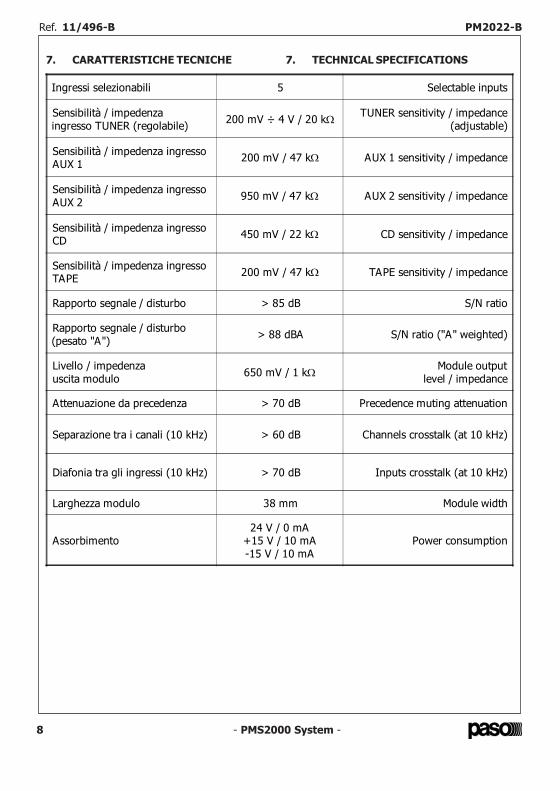
7. CARATTERISTICHE TECNICHE 7. TECHNICAL SPECIFICATIONS
Ingressi selezionabili 5 Selectable inputs
Sensibilità / impedenzaingresso TUNER (regolabile) 200 mV ÷ 4 V / 20 kΩ TUNER sensitivity / impedance
(adjustable)
Sensibilità / impedenza ingressoAUX 1 200 mV / 47 kΩ AUX 1 sensitivity / impedance
Sensibilità / impedenza ingressoAUX 2 950 mV / 47 kΩ AUX 2 sensitivity / impedance
Sensibilità / impedenza ingressoCD 450 mV / 22 kΩ CD sensitivity / impedance
Sensibilità / impedenza ingressoTAPE 200 mV / 47 kΩ TAPE sensitivity / impedance
Rapporto segnale / disturbo > 85 dB S/N ratio
Rapporto segnale / disturbo(pesato "A") > 88 dBA S/N ratio ("A" weighted)
Livello / impedenzauscita modulo 650 mV / 1 kΩ Module output
level / impedance
Attenuazione da precedenza > 70 dB Precedence muting attenuation
Separazione tra i canali (10 kHz) > 60 dB Channels crosstalk (at 10 kHz)
Diafonia tra gli ingressi (10 kHz) > 70 dB Inputs crosstalk (at 10 kHz)
Larghezza modulo 38 mm Module width
Assorbimento24 V / 0 mA
+15 V / 10 mA-15 V / 10 mA
Power consumption
- PMS2000 System - 17
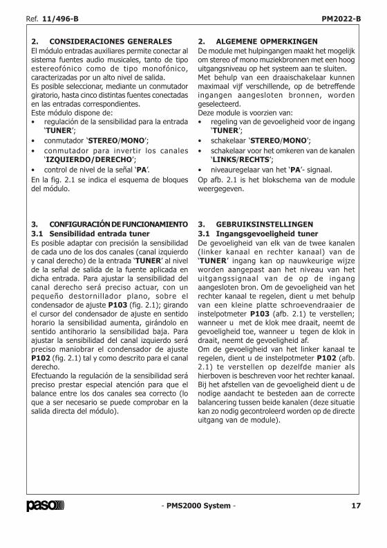
2. CONSIDERACIONES GENERALESEl módulo entradas auxiliares permite conectar alsistema fuentes audio musicales, tanto de tipoestereofónico como de tipo monofónico,caracterizadas por un alto nivel de salida.Es posible seleccionar, mediante un conmutadorgiratorio, hasta cinco distintas fuentes conectadasen las entradas correspondientes.Este módulo dispone de:• regulación de la sensibilidad para la entrada
‘TUNER’;• conmutador ‘STEREO/MONO’;• conmutador para invertir los canales
‘IZQUIERDO/DERECHO’;• control de nivel de la señal ‘PA’.En la fig. 2.1 se indica el esquema de bloquesdel módulo.
2. ALGEMENE OPMERKINGENDe module met hulpingangen maakt het mogelijkom stereo of mono muziekbronnen met een hooguitgangsniveau op het systeem aan te sluiten.Met behulp van een draaischakelaar kunnenmaximaal vijf verschillende, op de betreffendeingangen aangesloten bronnen, wordengeselecteerd.Deze module is voorzien van:• regeling van de gevoeligheid voor de ingang
‘TUNER’;• schakelaar ‘STEREO/MONO’;• schakelaar voor het omkeren van de kanalen
‘LINKS/RECHTS’;• niveauregelaar van het ‘PA’- signaal.Op afb. 2.1 is het blokschema van de moduleweergegeven.
3. CONFIGURACIÓN DE FUNCIONAMIENTO3.1 Sensibilidad entrada tunerEs posible adaptar con precisión la sensibilidadde cada uno de los dos canales (canal izquierdoy canal derecho) de la entrada ‘TUNER’ al nivelde la señal de salida de la fuente aplicada endicha entrada. Para ajustar la sensibilidad delcanal derecho será preciso actuar, con unpequeño destornil lador plano, sobre elcondensador de ajuste P103 (fig. 2.1); girandoel cursor del condensador de ajuste en sentidohorario la sensibilidad aumenta, girándolo ensentido antihorario la sensibilidad baja. Paraajustar la sensibilidad del canal izquierdo serápreciso maniobrar el condensador de ajusteP102 (fig. 2.1) tal y como descrito para el canalderecho.Efectuando la regulación de la sensibilidad serápreciso prestar especial atención para que elbalance entre los dos canales sea correcto (loque a ser necesario se puede comprobar en lasalida directa del módulo).
3. GEBRUIKSINSTELLINGEN3.1 Ingangsgevoeligheid tunerDe gevoeligheid van elk van de twee kanalen(linker kanaal en rechter kanaal) van de‘TUNER’ ingang kan op nauwkeurige wijzeworden aangepast aan het niveau van hetuitgangssignaal van de op de ingangaangesloten bron. Om de gevoeligheid van hetrechter kanaal te regelen, dient u met behulpvan een kleine platte schroevendraaier deinstelpotmeter P103 (afb. 2.1) te verstellen;wanneer u met de klok mee draait, neemt degevoeligheid toe, wanneer u tegen de klok indraait, neemt de gevoeligheid af.Om de gevoeligheid van het linker kanaal teregelen, dient u de instelpotmeter P102 (afb.2.1) te verstellen op dezelfde manier alshierboven is beschreven voor het rechter kanaal.Bij het afstellen van de gevoeligheid dient u denodige aandacht te besteden aan de correctebalancering tussen beide kanalen (deze situatiekan zo nodig gecontroleerd worden op de directeuitgang van de module).
Ref. 11/496-B PM2022-B Ref. 11/496-B PM2022-B
- PMS2000 System - 9
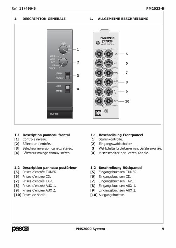
1.1 Description panneau frontal[1] Contrôle niveau.[2] Sélecteur d'entrée.[3] Sélecteur inversion canaux stéréo.[4] Sélecteur mixage canaux stéréo.
1.1 Beschreibung Frontpaneel[1] Stufenkontrolle.[2] Eingangswahlschalter.[3] Wahlschalter für die Umkehrung der Stereokanäle.[4] Mischschalter der Stereo-Kanäle.
1.2 Description panneau postérieur[5] Prises d'entrée TUNER.[6] Prises d'entrée CD.[7] Prises d'entrée TAPE.[8] Prises d'entrée AUX 1.[9] Prises d'entrée AUX 2.[10] Prises de sortie.
1.2 Beschreibung Rückpaneel[5] Eingangsbuchsen TUNER.[6] Eingangsbuchsen CD.[7] Eingangsbuchsen TAPE.[8] Eingangsbuchsen AUX 1.[9] Eingangsbuchsen AUX 2.[10] Ausgangsbuchse.
1. DESCRIPTION GENERALE 1. ALLGEMEINE BESCHREIBUNG
- PMS2000 System -16
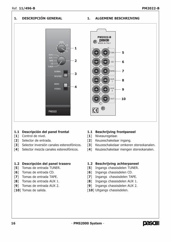
1.1 Descripción del panel frontal[1] Control de nivel.[2] Selector de entrada.[3] Selector inversión canales estereofónicos.[4] Selector mezcla canales estereofónicos.
1.1 Beschrijving frontpaneel[1] Niveauregelaar.[2] Keuzeschakelaar ingang.[3] Keuzeschakelaar omkeren stereokanalen.[4] Keuzeschakelaar mengen stereokanalen.
1.2 Descripción del panel trasero[5] Tomas de entrada TUNER.[6] Tomas de entrada CD.[7] Tomas de entrada TAPE.[8] Tomas de entrada AUX 1.[9] Tomas de entrada AUX 2.[10] Tomas de salida.
1.2 Beschrijving achterpaneel[5] Ingangs chassisdelen TUNER.[6] Ingangs chassisdelen CD.[7] Ingangs chassisdelen TAPE.[8] Ingangs chassisdelen AUX 1.[9] Ingangs chassisdelen AUX 2.[10] Uitgangs chassisdelen.
1. DESCRIPCIÓN GENERAL 1. ALGEMENE BESCHRIJVING
Ref. 11/496-B PM2022-B Ref. 11/496-B PM2022-B
- PMS2000 System -10
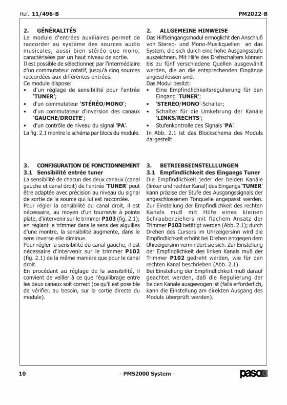
2. GÉNÉRALITÉSLe module d'entrées auxiliaires permet deraccorder au système des sources audiomusicales, aussi bien stéréo que mono,caractérisées par un haut niveau de sortie.Il est possible de sélectionner, par l'intermédiaired'un commutateur rotatif, jusqu'à cinq sourcesraccordées aux différentes entrées.Ce module dispose:• d'un réglage de sensibilité pour l'entrée
‘TUNER’;• d'un commutateur ‘STÉRÉO/MONO’;• d'un commutateur d'inversion des canaux
‘GAUCHE/DROITE’;• d'un contrôle de niveau du signal ‘PA’.La fig. 2.1 montre le schéma par blocs du module.
2. ALLGEMEINE HINWEISEDas Hilfseingangsmodul ermöglicht den Anschlußvon Stereo- und Mono-Musikquellen an dasSystem, die sich durch eine hohe Ausgangsstufeauszeichnen. Mit Hilfe des Drehschalters könnenbis zu fünf verschiedene Quellen ausgewähltwerden, die an die entsprechenden Eingängeangeschlossen sind.Das Modul besitzt:• Eine Empfindlichkeitsregulierung für den
Eingang ‘TUNER’;• ‘STEREO/MONO’-Schalter;• Schalter für die Umkehrung der Kanäle
‘LINKS/RECHTS’;• Stufenkontrolle des Signals ‘PA’.In Abb. 2.1 ist das Blockschema des Modulsdargestellt.
3. BETRIEBSEINSTELLLUNGEN3.1 Empfindlichkeit des Eingangs TunerDie Empfindlichkeit jeder der beiden Kanäle(linker und rechter Kanal) des Eingangs ‘TUNER’kann präzise der Stufe des Ausgangssignals derangeschlossenen Tonquelle angepasst werden.Zur Einstellung der Empfindlichkeit des rechtenKanals muß mit Hilfe eines kleinenSchraubenziehers mit flachem Ansatz derTrimmer P103 betätigt werden (Abb. 2.1); durchDrehen des Cursors im Uhrzeigersinn wird dieEmpfindlichkeit erhöht bei Drehen entgegen demUhrzeigersinn vermindert sie sich. Zur Einstellungder Empfindlichkeit des linken Kanals muß derTrimmer P102 gedreht werden, wie für denrechten Kanal beschrieben (Abb. 2.1).Bei Einstellung der Empfindlichkeit muß daraufgeachtet werden, daß die Regulierung derbeiden Kanäle ausgewogen ist (falls erforderlich,kann die Einstellung am direkten Ausgang desModuls überprüft werden).
3. CONFIGURATION DE FONCTIONNEMENT3.1 Sensibilité entrée tunerLa sensibilité de chacun des deux canaux (canalgauche et canal droit) de l'entrée ‘TUNER’ peutêtre adaptée avec précision au niveau du signalde sortie de la source qui lui est raccordée.Pour régler la sensibilité du canal droit, il estnécessaire, au moyen d'un tournevis à pointeplate, d'intervenir sur le trimmer P103 (fig. 2.1);en réglant le trimmer dans le sens des aiguillesd'une montre, la sensibilité augmente, dans lesens inverse elle diminue.Pour régler la sensibilité du canal gauche, il estnécessaire d'intervenir sur le trimmer P102(fig. 2.1) de la même manière que pour le canaldroit.En procédant au réglage de la sensibilité, ilconvient de veiller à ce que l'équilibrage entreles deux canaux soit correct (ce qu'il est possiblede vérifier, au besoin, sur la sortie directe dumodule).
- PMS2000 System - 15
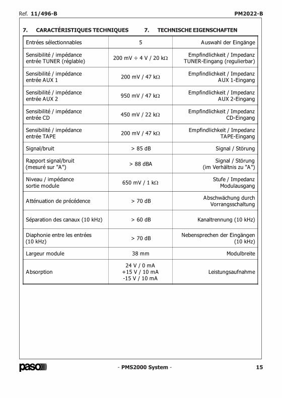
7. CARACTÉRISTIQUES TECHNIQUES 7. TECHNISCHE EIGENSCHAFTEN
Entrées sélectionnables 5 Auswahl der Eingänge
Sensibilité / impédanceentrée TUNER (réglable) 200 mV ÷ 4 V / 20 kΩ Empfindlichkeit / Impedanz
TUNER-Eingang (regulierbar)
Sensibilité / impédanceentrée AUX 1 200 mV / 47 kΩ Empfindlichkeit / Impedanz
AUX 1-Eingang
Sensibilité / impédanceentrée AUX 2 950 mV / 47 kΩ Empfindlichkeit / Impedanz
AUX 2-Eingang
Sensibilité / impédanceentrée CD 450 mV / 22 kΩ Empfindlichkeit / Impedanz
CD-Eingang
Sensibilité / impédanceentrée TAPE 200 mV / 47 kΩ Empfindlichkeit / Impedanz
TAPE-Eingang
Signal/bruit > 85 dB Signal / Störung
Rapport signal/bruit(mesuré sur "A") > 88 dBA Signal / Störung
(im Verhältnis zu "A")
Niveau / impédancesortie module 650 mV / 1 kΩ Stufe / Impedanz
Modulausgang
Atténuation de précédence > 70 dB Abschwächung durchVorrangsschaltung
Séparation des canaux (10 kHz) > 60 dB Kanaltrennung (10 kHz)
Diaphonie entre les entrées(10 kHz) > 70 dB Nebensprechen der Eingängen
(10 kHz)
Largeur module 38 mm Modulbreite
Absorption24 V / 0 mA
+15 V / 10 mA-15 V / 10 mA
Leistungsaufnahme
Ref. 11/496-B PM2022-B Ref. 11/496-B PM2022-B
- PMS2000 System - 11
Fig. /Abb. 2.1
Fig. /Abb. 3.1
A
B
C
- PMS2000 System -14
6. EINSTELLUNGEN UND GEBRAUCHDie Signale an den Buchsen ‘L’ und ‘R’ desgewählten Eingangs, werden nach derVorverstärkung an die Ausgangsbuchsen ‘OUT’und an den Stereomischbus weitergeleitet(rechte und linke Leitung).Diese Signale werden außerdem gemischt undnach entsprechender Einstellung der Amplitüde(über den Stufenregler LEVEL) an denMono-Mischbus (Bus PA) geleitet.
6.1 Wahlschalter für den EingangZum Auswahl eines Eingangs von fünf Ausgängendes Moduls.
6.2 Wahlschalter NORMAL/REVERSEMit diesem Wahlschalter werden die beidenStereokanäle umgekehrt.Der Regler ist insbesondere während derEinstellung der Anlage nützlich.
6.3 Wahlschalter MONO/STEREOWenn dieser Wahlschalter sich in der Position‘MONO’ befindet, bewirkt er die Mischung derbeiden Stereokanäle untereinander.
6.4 StufenkontrolleÜber die Stufenkontrolle ‘LEVEL’ [1] kann dieAmplitüde des Signals reguliert werden, das demMischbus PA des gewählten Eingangs zugeleitetwird.
6. RÉGLAGES ET UTILISATIONLes signaux appliqués aux prises ‘L’ et ‘R’ del 'entrée sélectionnée, après avoir étépréamplifiés, sont envoyés aux prises de sortie‘OUT’ et au bus de mixage stéréo (ligne droiteet ligne gauche).En outre, ces signaux sont mixés et transmis,après le réglage de leur amplitude (au moyendu contrôle LEVEL) au bus de mixage mono(bus PA).
6.1 Sélecteur d'entréePermet de sélectionner une des cinq entrées dumodule.
6.2 Sélecteur NORMAL/REVERSECe sélecteur permet d'intervertir les deux canauxstéréo.Ce contrôle s'avère d'une grande utilité durantla phase de mise au point du système.
6.3 Sélecteur MONO/STEREOLorsqu'il se trouve sur la position ‘MONO’, lesdeux canaux stéréo sont mixés.
6.4 Contrôle de niveauLe contrôle ‘LEVEL’ [1] permet de réglerl'amplitude du signal transmis au bus de mixagePA relatif à l'entrée sélectionnée.
Ref. 11/496-B PM2022-B Ref. 11/496-B PM2022-B
LEVEL
NORMAL / REVERSE
SELECTOR
TUNER
CD
TAPE IN
AUX 1
AUX 2
OUT
MONO / STEREO
SELECTOR
MUTINGDEVICE
MUTINGDEVICE
SUMMINGSTAGE
AMPLIFIERSTAGES
MUTE IN
PA BUS IN
PA BUS OUT
LEFT BUS
RIGHT BUS
MUTE OUT
MODULE
MULTIPOLE
CONNECTOR
P102
CN102
P103
INPUTSELECTOR
CN104
CN103
CN
106
CN
107
- PMS2000 System -12
3.2 Interruption par ligne d'assourdissementLorsqu'une condition de priorité est détectée surla terminaison prévue à cet effet (MUTE IN) duconnecteur à plusieurs voies du module, lessignaux relatifs transmis au bus de mixage stéréo(bus du canal gauche et bus du canal droit) sontinterrompus (configuration prédéfinie).Pour désactiver cette fonction, il est nécessairede retirer le cavalier de court-circuit présent surles terminaisons du connecteur CN102( fig. 2.1).
NOTELa ligne d'assourdissement en entrée arrive,indépendamment de la présence ou de l'absencedu cavalier ci-dessus, sur la terminaison‘MUTE OUT’ du connecteur à plusieurs voies etest transmise au module suivant (ligned'assourdissement en sortie).
3.2 Stummschaltung der Muting-LeitungWenn eine Vorrangbedingung vom entsprechendenEndstück (MUTE IN) des Mehrwege-Anschlussesdes Moduls wahrgenommen wird, werden die anden Stereo-Mischbus geleiteten Signalestummgeschaltet (Default-Einstellung) (Bus desrechten Kanals und Bus des linken Kanals).Zur Ausschaltung dieser Funktion muß diekurzschließende Überbrückung auf den Endtückendes Verbindungsstücks CN102 (Abb. 2.1) entferntwerden.
ANMERKUNGDie e ingehende Mut ing-Lei tung wird,unabhängig vom Vorhandensein der genanntenKurzschlußüberbrückung an das Endstück‘MUTE OUT’ des Mehrwege-Anschlusses undan dann das d i rekt fo lgende Modulweitergeleitet (austretende Muting-Leitung).
4. INSTALLATIONLe module double entrée doit être installé sur lesupport PMS2002-B en suivant les instructionsde montage jointes à ce dernier.Il est rappelé que sa position par rapport auxautres modules d'entrée installés sur le système,conditionne les niveaux de priorité.Plus précisément: pour que les signaux dessources musicales puissent être coupés par lesmodules “double entrée” (ou par les modulesdisposant des contacts permettant l'activation dela condition de précédence), le module d'entréedes auxiliaires doit être installé à droite de cesderniers; en règle générale, un module doubleentrée ne peut pas assourdir les signaux desmodules installés à sa gauche.
NOTEPour que les signaux transmis au bus stéréosoient également coupés, le cavalier de court-circuit doit être maintenu sur les terminaisonsdu connecteur CN102 (voir chap. 3.2).
4. INSTALLATIONDas Doppeleingangsmodul muß entsprechend dendem Aufnahmekorb PMS2002-B beiliegendenMontageanweisungen im Korb installiert werden.Es wird daran erinnert, daß seine Position, imVerhältnis zu den anderen im System installiertenEingangsmodulen, seine Vorrangstufe bestimmt.Das bedeutet: zur Stummschaltung der Signale derMusikquellen über die “Doppeleingangsmodule”(oder die Module, die die entsprechendenKontakte für die Freigabe der Vorrangsbedingungbesitzen), muß das Hilfseingangsmodul rechtsdieser Module installiert werden; normalerweisekann ein Doppeleingangsmodul nicht die Signaleder weiter links von ihm installierten Modulestummschalten.
ANMERKUNGZur Stummschaltung der Signale an denStereobussen, muß die kurzschließendeÜberbrückung auf den Endstücken desAnschlußstücks CN102 belassen werden (sieheAbschnitt 3.2).
- PMS2000 System - 13
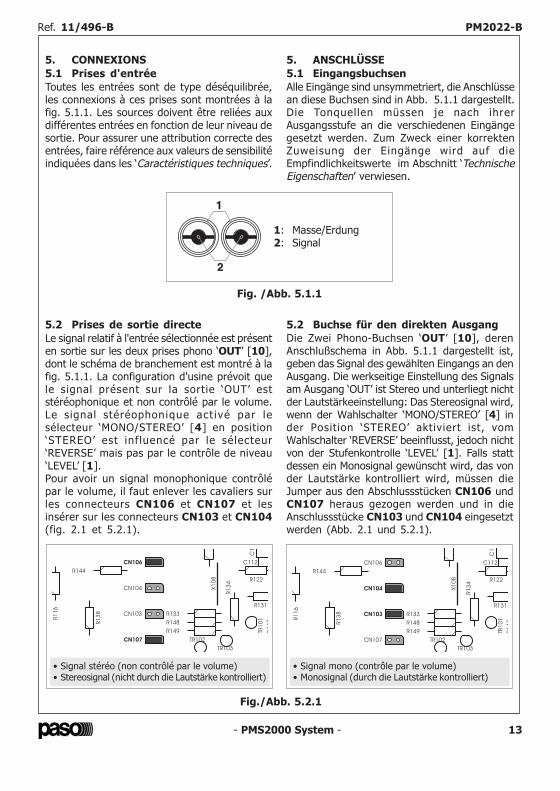
5. CONNEXIONS5.1 Prises d'entréeToutes les entrées sont de type déséquilibrée,les connexions à ces prises sont montrées à lafig. 5.1.1. Les sources doivent être reliées auxdifférentes entrées en fonction de leur niveau desortie. Pour assurer une attribution correcte desentrées, faire référence aux valeurs de sensibilitéindiquées dans les ‘Caractéristiques techniques’.
5. ANSCHLÜSSE5.1 EingangsbuchsenAlle Eingänge sind unsymmetriert, die Anschlüssean diese Buchsen sind in Abb. 5.1.1 dargestellt.Die Tonquellen müssen je nach ihrerAusgangsstufe an die verschiedenen Eingängegesetzt werden. Zum Zweck einer korrektenZuweisung der Eingänge wird auf dieEmpfindlichkeitswerte im Abschnitt ‘TechnischeEigenschaften’ verwiesen.
5.2 Prises de sortie directeLe signal relatif à l'entrée sélectionnée est présenten sortie sur les deux prises phono ‘OUT’ [10],dont le schéma de branchement est montré à lafig. 5.1.1. La configuration d'usine prévoit quele signal présent sur la sortie ‘OUT’ eststéréophonique et non contrôlé par le volume.Le signal stéréophonique act ivé par lesélecteur ‘MONO/STEREO’ [4] en position‘STEREO’ est inf luencé par le sélecteur‘REVERSE’ mais pas par le contrôle de niveau‘LEVEL’ [1].Pour avoir un signal monophonique contrôlépar le volume, il faut enlever les cavaliers surles connecteurs CN106 et CN107 et lesinsérer sur les connecteurs CN103 et CN104(fig. 2.1 et 5.2.1).
5.2 Buchse für den direkten AusgangDie Zwei Phono-Buchsen ‘OUT’ [10], derenAnschlußschema in Abb. 5.1.1 dargestellt ist,geben das Signal des gewählten Eingangs an denAusgang. Die werkseitige Einstellung des Signalsam Ausgang ‘OUT’ ist Stereo und unterliegt nichtder Lautstärkeeinstellung: Das Stereosignal wird,wenn der Wahlschalter ‘MONO/STEREO’ [4] inder Position ‘STEREO’ aktiviert ist, vomWahlschalter ‘REVERSE’ beeinflusst, jedoch nichtvon der Stufenkontrolle ‘LEVEL’ [1]. Falls stattdessen ein Monosignal gewünscht wird, das vonder Lautstärke kontrolliert wird, müssen dieJumper aus den Abschlussstücken CN106 undCN107 heraus gezogen werden und in dieAnschlussstücke CN103 und CN104 eingesetztwerden (Abb. 2.1 und 5.2.1).
Fig. /Abb. 5.1.1
1
2
1: Masse/Erdung2: Signal
Ref. 11/496-B PM2022-B Ref. 11/496-B PM2022-B
Fig./Abb. 5.2.1
C1
R1
16
R144
R122
TR102
C 02
A
X1
08
C112
R1
47
TR103
R1
38 CN103
CN106
CN107
CN104
R149
R1
34
R148
TR1
01
R133
R131
• Signal stéréo (non contrôlé par le volume)• Stereosignal (nicht durch die Lautstärke kontrolliert)
C1
0
R1
16
R144
R122
TR102
C 02
A
X1
08
C112
R1
47
TR103
R1
38 CN103
CN106
CN107
CN104
R149
R1
34
R148
TR1
01
R133
R131
• Signal mono (contrôle par le volume)• Monosignal (durch die Lautstärke kontrolliert)
- PMS2000 System -12
3.2 Interruption par ligne d'assourdissementLorsqu'une condition de priorité est détectée surla terminaison prévue à cet effet (MUTE IN) duconnecteur à plusieurs voies du module, lessignaux relatifs transmis au bus de mixage stéréo(bus du canal gauche et bus du canal droit) sontinterrompus (configuration prédéfinie).Pour désactiver cette fonction, il est nécessairede retirer le cavalier de court-circuit présent surles terminaisons du connecteur CN102( fig. 2.1).
NOTELa ligne d'assourdissement en entrée arrive,indépendamment de la présence ou de l'absencedu cavalier ci-dessus, sur la terminaison‘MUTE OUT’ du connecteur à plusieurs voies etest transmise au module suivant (ligned'assourdissement en sortie).
3.2 Stummschaltung der Muting-LeitungWenn eine Vorrangbedingung vom entsprechendenEndstück (MUTE IN) des Mehrwege-Anschlussesdes Moduls wahrgenommen wird, werden die anden Stereo-Mischbus geleiteten Signalestummgeschaltet (Default-Einstellung) (Bus desrechten Kanals und Bus des linken Kanals).Zur Ausschaltung dieser Funktion muß diekurzschließende Überbrückung auf den Endtückendes Verbindungsstücks CN102 (Abb. 2.1) entferntwerden.
ANMERKUNGDie e ingehende Mut ing-Lei tung wird,unabhängig vom Vorhandensein der genanntenKurzschlußüberbrückung an das Endstück‘MUTE OUT’ des Mehrwege-Anschlusses undan dann das d i rekt fo lgende Modulweitergeleitet (austretende Muting-Leitung).
4. INSTALLATIONLe module double entrée doit être installé sur lesupport PMS2002-B en suivant les instructionsde montage jointes à ce dernier.Il est rappelé que sa position par rapport auxautres modules d'entrée installés sur le système,conditionne les niveaux de priorité.Plus précisément: pour que les signaux dessources musicales puissent être coupés par lesmodules “double entrée” (ou par les modulesdisposant des contacts permettant l'activation dela condition de précédence), le module d'entréedes auxiliaires doit être installé à droite de cesderniers; en règle générale, un module doubleentrée ne peut pas assourdir les signaux desmodules installés à sa gauche.
NOTEPour que les signaux transmis au bus stéréosoient également coupés, le cavalier de court-circuit doit être maintenu sur les terminaisonsdu connecteur CN102 (voir chap. 3.2).
4. INSTALLATIONDas Doppeleingangsmodul muß entsprechend dendem Aufnahmekorb PMS2002-B beiliegendenMontageanweisungen im Korb installiert werden.Es wird daran erinnert, daß seine Position, imVerhältnis zu den anderen im System installiertenEingangsmodulen, seine Vorrangstufe bestimmt.Das bedeutet: zur Stummschaltung der Signale derMusikquellen über die “Doppeleingangsmodule”(oder die Module, die die entsprechendenKontakte für die Freigabe der Vorrangsbedingungbesitzen), muß das Hilfseingangsmodul rechtsdieser Module installiert werden; normalerweisekann ein Doppeleingangsmodul nicht die Signaleder weiter links von ihm installierten Modulestummschalten.
ANMERKUNGZur Stummschaltung der Signale an denStereobussen, muß die kurzschließendeÜberbrückung auf den Endstücken desAnschlußstücks CN102 belassen werden (sieheAbschnitt 3.2).
- PMS2000 System - 13
5. CONNEXIONS5.1 Prises d'entréeToutes les entrées sont de type déséquilibrée,les connexions à ces prises sont montrées à lafig. 5.1.1. Les sources doivent être reliées auxdifférentes entrées en fonction de leur niveau desortie. Pour assurer une attribution correcte desentrées, faire référence aux valeurs de sensibilitéindiquées dans les ‘Caractéristiques techniques’.
5. ANSCHLÜSSE5.1 EingangsbuchsenAlle Eingänge sind unsymmetriert, die Anschlüssean diese Buchsen sind in Abb. 5.1.1 dargestellt.Die Tonquellen müssen je nach ihrerAusgangsstufe an die verschiedenen Eingängegesetzt werden. Zum Zweck einer korrektenZuweisung der Eingänge wird auf dieEmpfindlichkeitswerte im Abschnitt ‘TechnischeEigenschaften’ verwiesen.
5.2 Prises de sortie directeLe signal relatif à l'entrée sélectionnée est présenten sortie sur les deux prises phono ‘OUT’ [10],dont le schéma de branchement est montré à lafig. 5.1.1. La configuration d'usine prévoit quele signal présent sur la sortie ‘OUT’ eststéréophonique et non contrôlé par le volume.Le signal stéréophonique act ivé par lesélecteur ‘MONO/STEREO’ [4] en position‘STEREO’ est inf luencé par le sélecteur‘REVERSE’ mais pas par le contrôle de niveau‘LEVEL’ [1].Pour avoir un signal monophonique contrôlépar le volume, il faut enlever les cavaliers surles connecteurs CN106 et CN107 et lesinsérer sur les connecteurs CN103 et CN104(fig. 2.1 et 5.2.1).
5.2 Buchse für den direkten AusgangDie Zwei Phono-Buchsen ‘OUT’ [10], derenAnschlußschema in Abb. 5.1.1 dargestellt ist,geben das Signal des gewählten Eingangs an denAusgang. Die werkseitige Einstellung des Signalsam Ausgang ‘OUT’ ist Stereo und unterliegt nichtder Lautstärkeeinstellung: Das Stereosignal wird,wenn der Wahlschalter ‘MONO/STEREO’ [4] inder Position ‘STEREO’ aktiviert ist, vomWahlschalter ‘REVERSE’ beeinflusst, jedoch nichtvon der Stufenkontrolle ‘LEVEL’ [1]. Falls stattdessen ein Monosignal gewünscht wird, das vonder Lautstärke kontrolliert wird, müssen dieJumper aus den Abschlussstücken CN106 undCN107 heraus gezogen werden und in dieAnschlussstücke CN103 und CN104 eingesetztwerden (Abb. 2.1 und 5.2.1).
Fig. /Abb. 5.1.1
1
2
1: Masse/Erdung2: Signal
Ref. 11/496-B PM2022-B Ref. 11/496-B PM2022-B
Fig./Abb. 5.2.1
C1
R1
16
R144
R122
TR102
C 02
A
X1
08
C112
R1
47
TR103
R1
38 CN103
CN106
CN107
CN104
R149
R1
34
R148
TR1
01
R133
R131
• Signal stéréo (non contrôlé par le volume)• Stereosignal (nicht durch die Lautstärke kontrolliert)
C1
0
R1
16
R144
R122
TR102
C 02
A
X1
08
C112
R1
47
TR103
R1
38 CN103
CN106
CN107
CN104
R149
R1
34
R148
TR1
01
R133
R131
• Signal mono (contrôle par le volume)• Monosignal (durch die Lautstärke kontrolliert)
- PMS2000 System - 11
Fig. /Abb. 2.1
Fig. /Abb. 3.1
A
B
C
- PMS2000 System -14
6. EINSTELLUNGEN UND GEBRAUCHDie Signale an den Buchsen ‘L’ und ‘R’ desgewählten Eingangs, werden nach derVorverstärkung an die Ausgangsbuchsen ‘OUT’und an den Stereomischbus weitergeleitet(rechte und linke Leitung).Diese Signale werden außerdem gemischt undnach entsprechender Einstellung der Amplitüde(über den Stufenregler LEVEL) an denMono-Mischbus (Bus PA) geleitet.
6.1 Wahlschalter für den EingangZum Auswahl eines Eingangs von fünf Ausgängendes Moduls.
6.2 Wahlschalter NORMAL/REVERSEMit diesem Wahlschalter werden die beidenStereokanäle umgekehrt.Der Regler ist insbesondere während derEinstellung der Anlage nützlich.
6.3 Wahlschalter MONO/STEREOWenn dieser Wahlschalter sich in der Position‘MONO’ befindet, bewirkt er die Mischung derbeiden Stereokanäle untereinander.
6.4 StufenkontrolleÜber die Stufenkontrolle ‘LEVEL’ [1] kann dieAmplitüde des Signals reguliert werden, das demMischbus PA des gewählten Eingangs zugeleitetwird.
6. RÉGLAGES ET UTILISATIONLes signaux appliqués aux prises ‘L’ et ‘R’ del 'entrée sélectionnée, après avoir étépréamplifiés, sont envoyés aux prises de sortie‘OUT’ et au bus de mixage stéréo (ligne droiteet ligne gauche).En outre, ces signaux sont mixés et transmis,après le réglage de leur amplitude (au moyendu contrôle LEVEL) au bus de mixage mono(bus PA).
6.1 Sélecteur d'entréePermet de sélectionner une des cinq entrées dumodule.
6.2 Sélecteur NORMAL/REVERSECe sélecteur permet d'intervertir les deux canauxstéréo.Ce contrôle s'avère d'une grande utilité durantla phase de mise au point du système.
6.3 Sélecteur MONO/STEREOLorsqu'il se trouve sur la position ‘MONO’, lesdeux canaux stéréo sont mixés.
6.4 Contrôle de niveauLe contrôle ‘LEVEL’ [1] permet de réglerl'amplitude du signal transmis au bus de mixagePA relatif à l'entrée sélectionnée.
Ref. 11/496-B PM2022-B Ref. 11/496-B PM2022-B
LEVEL
NORMAL / REVERSE
SELECTOR
TUNER
CD
TAPE IN
AUX 1
AUX 2
OUT
MONO / STEREO
SELECTOR
MUTINGDEVICE
MUTINGDEVICE
SUMMINGSTAGE
AMPLIFIERSTAGES
MUTE IN
PA BUS IN
PA BUS OUT
LEFT BUS
RIGHT BUS
MUTE OUT
MODULE
MULTIPOLE
CONNECTOR
P102
CN102
P103
INPUTSELECTOR
CN104
CN103
CN
106
CN
107
- PMS2000 System -10
2. GÉNÉRALITÉSLe module d'entrées auxiliaires permet deraccorder au système des sources audiomusicales, aussi bien stéréo que mono,caractérisées par un haut niveau de sortie.Il est possible de sélectionner, par l'intermédiaired'un commutateur rotatif, jusqu'à cinq sourcesraccordées aux différentes entrées.Ce module dispose:• d'un réglage de sensibilité pour l'entrée
‘TUNER’;• d'un commutateur ‘STÉRÉO/MONO’;• d'un commutateur d'inversion des canaux
‘GAUCHE/DROITE’;• d'un contrôle de niveau du signal ‘PA’.La fig. 2.1 montre le schéma par blocs du module.
2. ALLGEMEINE HINWEISEDas Hilfseingangsmodul ermöglicht den Anschlußvon Stereo- und Mono-Musikquellen an dasSystem, die sich durch eine hohe Ausgangsstufeauszeichnen. Mit Hilfe des Drehschalters könnenbis zu fünf verschiedene Quellen ausgewähltwerden, die an die entsprechenden Eingängeangeschlossen sind.Das Modul besitzt:• Eine Empfindlichkeitsregulierung für den
Eingang ‘TUNER’;• ‘STEREO/MONO’-Schalter;• Schalter für die Umkehrung der Kanäle
‘LINKS/RECHTS’;• Stufenkontrolle des Signals ‘PA’.In Abb. 2.1 ist das Blockschema des Modulsdargestellt.
3. BETRIEBSEINSTELLLUNGEN3.1 Empfindlichkeit des Eingangs TunerDie Empfindlichkeit jeder der beiden Kanäle(linker und rechter Kanal) des Eingangs ‘TUNER’kann präzise der Stufe des Ausgangssignals derangeschlossenen Tonquelle angepasst werden.Zur Einstellung der Empfindlichkeit des rechtenKanals muß mit Hilfe eines kleinenSchraubenziehers mit flachem Ansatz derTrimmer P103 betätigt werden (Abb. 2.1); durchDrehen des Cursors im Uhrzeigersinn wird dieEmpfindlichkeit erhöht bei Drehen entgegen demUhrzeigersinn vermindert sie sich. Zur Einstellungder Empfindlichkeit des linken Kanals muß derTrimmer P102 gedreht werden, wie für denrechten Kanal beschrieben (Abb. 2.1).Bei Einstellung der Empfindlichkeit muß daraufgeachtet werden, daß die Regulierung derbeiden Kanäle ausgewogen ist (falls erforderlich,kann die Einstellung am direkten Ausgang desModuls überprüft werden).
3. CONFIGURATION DE FONCTIONNEMENT3.1 Sensibilité entrée tunerLa sensibilité de chacun des deux canaux (canalgauche et canal droit) de l'entrée ‘TUNER’ peutêtre adaptée avec précision au niveau du signalde sortie de la source qui lui est raccordée.Pour régler la sensibilité du canal droit, il estnécessaire, au moyen d'un tournevis à pointeplate, d'intervenir sur le trimmer P103 (fig. 2.1);en réglant le trimmer dans le sens des aiguillesd'une montre, la sensibilité augmente, dans lesens inverse elle diminue.Pour régler la sensibilité du canal gauche, il estnécessaire d'intervenir sur le trimmer P102(fig. 2.1) de la même manière que pour le canaldroit.En procédant au réglage de la sensibilité, ilconvient de veiller à ce que l'équilibrage entreles deux canaux soit correct (ce qu'il est possiblede vérifier, au besoin, sur la sortie directe dumodule).
- PMS2000 System - 15
7. CARACTÉRISTIQUES TECHNIQUES 7. TECHNISCHE EIGENSCHAFTEN
Entrées sélectionnables 5 Auswahl der Eingänge
Sensibilité / impédanceentrée TUNER (réglable) 200 mV ÷ 4 V / 20 kΩ Empfindlichkeit / Impedanz
TUNER-Eingang (regulierbar)
Sensibilité / impédanceentrée AUX 1 200 mV / 47 kΩ Empfindlichkeit / Impedanz
AUX 1-Eingang
Sensibilité / impédanceentrée AUX 2 950 mV / 47 kΩ Empfindlichkeit / Impedanz
AUX 2-Eingang
Sensibilité / impédanceentrée CD 450 mV / 22 kΩ Empfindlichkeit / Impedanz
CD-Eingang
Sensibilité / impédanceentrée TAPE 200 mV / 47 kΩ Empfindlichkeit / Impedanz
TAPE-Eingang
Signal/bruit > 85 dB Signal / Störung
Rapport signal/bruit(mesuré sur "A") > 88 dBA Signal / Störung
(im Verhältnis zu "A")
Niveau / impédancesortie module 650 mV / 1 kΩ Stufe / Impedanz
Modulausgang
Atténuation de précédence > 70 dB Abschwächung durchVorrangsschaltung
Séparation des canaux (10 kHz) > 60 dB Kanaltrennung (10 kHz)
Diaphonie entre les entrées(10 kHz) > 70 dB Nebensprechen der Eingängen
(10 kHz)
Largeur module 38 mm Modulbreite
Absorption24 V / 0 mA
+15 V / 10 mA-15 V / 10 mA
Leistungsaufnahme
Ref. 11/496-B PM2022-B Ref. 11/496-B PM2022-B
- PMS2000 System - 9
1.1 Description panneau frontal[1] Contrôle niveau.[2] Sélecteur d'entrée.[3] Sélecteur inversion canaux stéréo.[4] Sélecteur mixage canaux stéréo.
1.1 Beschreibung Frontpaneel[1] Stufenkontrolle.[2] Eingangswahlschalter.[3] Wahlschalter für die Umkehrung der Stereokanäle.[4] Mischschalter der Stereo-Kanäle.
1.2 Description panneau postérieur[5] Prises d'entrée TUNER.[6] Prises d'entrée CD.[7] Prises d'entrée TAPE.[8] Prises d'entrée AUX 1.[9] Prises d'entrée AUX 2.[10] Prises de sortie.
1.2 Beschreibung Rückpaneel[5] Eingangsbuchsen TUNER.[6] Eingangsbuchsen CD.[7] Eingangsbuchsen TAPE.[8] Eingangsbuchsen AUX 1.[9] Eingangsbuchsen AUX 2.[10] Ausgangsbuchse.
1. DESCRIPTION GENERALE 1. ALLGEMEINE BESCHREIBUNG
- PMS2000 System -16
1.1 Descripción del panel frontal[1] Control de nivel.[2] Selector de entrada.[3] Selector inversión canales estereofónicos.[4] Selector mezcla canales estereofónicos.
1.1 Beschrijving frontpaneel[1] Niveauregelaar.[2] Keuzeschakelaar ingang.[3] Keuzeschakelaar omkeren stereokanalen.[4] Keuzeschakelaar mengen stereokanalen.
1.2 Descripción del panel trasero[5] Tomas de entrada TUNER.[6] Tomas de entrada CD.[7] Tomas de entrada TAPE.[8] Tomas de entrada AUX 1.[9] Tomas de entrada AUX 2.[10] Tomas de salida.
1.2 Beschrijving achterpaneel[5] Ingangs chassisdelen TUNER.[6] Ingangs chassisdelen CD.[7] Ingangs chassisdelen TAPE.[8] Ingangs chassisdelen AUX 1.[9] Ingangs chassisdelen AUX 2.[10] Uitgangs chassisdelen.
1. DESCRIPCIÓN GENERAL 1. ALGEMENE BESCHRIJVING
Ref. 11/496-B PM2022-B Ref. 11/496-B PM2022-B
- PMS2000 System -8
7. CARATTERISTICHE TECNICHE 7. TECHNICAL SPECIFICATIONS
Ingressi selezionabili 5 Selectable inputs
Sensibilità / impedenzaingresso TUNER (regolabile) 200 mV ÷ 4 V / 20 kΩ TUNER sensitivity / impedance
(adjustable)
Sensibilità / impedenza ingressoAUX 1 200 mV / 47 kΩ AUX 1 sensitivity / impedance
Sensibilità / impedenza ingressoAUX 2 950 mV / 47 kΩ AUX 2 sensitivity / impedance
Sensibilità / impedenza ingressoCD 450 mV / 22 kΩ CD sensitivity / impedance
Sensibilità / impedenza ingressoTAPE 200 mV / 47 kΩ TAPE sensitivity / impedance
Rapporto segnale / disturbo > 85 dB S/N ratio
Rapporto segnale / disturbo(pesato "A") > 88 dBA S/N ratio ("A" weighted)
Livello / impedenzauscita modulo 650 mV / 1 kΩ Module output
level / impedance
Attenuazione da precedenza > 70 dB Precedence muting attenuation
Separazione tra i canali (10 kHz) > 60 dB Channels crosstalk (at 10 kHz)
Diafonia tra gli ingressi (10 kHz) > 70 dB Inputs crosstalk (at 10 kHz)
Larghezza modulo 38 mm Module width
Assorbimento24 V / 0 mA
+15 V / 10 mA-15 V / 10 mA
Power consumption
- PMS2000 System - 17
2. CONSIDERACIONES GENERALESEl módulo entradas auxiliares permite conectar alsistema fuentes audio musicales, tanto de tipoestereofónico como de tipo monofónico,caracterizadas por un alto nivel de salida.Es posible seleccionar, mediante un conmutadorgiratorio, hasta cinco distintas fuentes conectadasen las entradas correspondientes.Este módulo dispone de:• regulación de la sensibilidad para la entrada
‘TUNER’;• conmutador ‘STEREO/MONO’;• conmutador para invertir los canales
‘IZQUIERDO/DERECHO’;• control de nivel de la señal ‘PA’.En la fig. 2.1 se indica el esquema de bloquesdel módulo.
2. ALGEMENE OPMERKINGENDe module met hulpingangen maakt het mogelijkom stereo of mono muziekbronnen met een hooguitgangsniveau op het systeem aan te sluiten.Met behulp van een draaischakelaar kunnenmaximaal vijf verschillende, op de betreffendeingangen aangesloten bronnen, wordengeselecteerd.Deze module is voorzien van:• regeling van de gevoeligheid voor de ingang
‘TUNER’;• schakelaar ‘STEREO/MONO’;• schakelaar voor het omkeren van de kanalen
‘LINKS/RECHTS’;• niveauregelaar van het ‘PA’- signaal.Op afb. 2.1 is het blokschema van de moduleweergegeven.
3. CONFIGURACIÓN DE FUNCIONAMIENTO3.1 Sensibilidad entrada tunerEs posible adaptar con precisión la sensibilidadde cada uno de los dos canales (canal izquierdoy canal derecho) de la entrada ‘TUNER’ al nivelde la señal de salida de la fuente aplicada endicha entrada. Para ajustar la sensibilidad delcanal derecho será preciso actuar, con unpequeño destornil lador plano, sobre elcondensador de ajuste P103 (fig. 2.1); girandoel cursor del condensador de ajuste en sentidohorario la sensibilidad aumenta, girándolo ensentido antihorario la sensibilidad baja. Paraajustar la sensibilidad del canal izquierdo serápreciso maniobrar el condensador de ajusteP102 (fig. 2.1) tal y como descrito para el canalderecho.Efectuando la regulación de la sensibilidad serápreciso prestar especial atención para que elbalance entre los dos canales sea correcto (loque a ser necesario se puede comprobar en lasalida directa del módulo).
3. GEBRUIKSINSTELLINGEN3.1 Ingangsgevoeligheid tunerDe gevoeligheid van elk van de twee kanalen(linker kanaal en rechter kanaal) van de‘TUNER’ ingang kan op nauwkeurige wijzeworden aangepast aan het niveau van hetuitgangssignaal van de op de ingangaangesloten bron. Om de gevoeligheid van hetrechter kanaal te regelen, dient u met behulpvan een kleine platte schroevendraaier deinstelpotmeter P103 (afb. 2.1) te verstellen;wanneer u met de klok mee draait, neemt degevoeligheid toe, wanneer u tegen de klok indraait, neemt de gevoeligheid af.Om de gevoeligheid van het linker kanaal teregelen, dient u de instelpotmeter P102 (afb.2.1) te verstellen op dezelfde manier alshierboven is beschreven voor het rechter kanaal.Bij het afstellen van de gevoeligheid dient u denodige aandacht te besteden aan de correctebalancering tussen beide kanalen (deze situatiekan zo nodig gecontroleerd worden op de directeuitgang van de module).
Ref. 11/496-B PM2022-B Ref. 11/496-B PM2022-B
- PMS2000 System - 7
6. ADJUSTMENTS AND USEAfter being pre-amplified, the signals appliedto the ‘L’ and ‘R’ sockets of the selected inputare sent to the ‘OUT’ output sockets and to thestereo mixing bus (right line and left line).
These signals are also mixed and sent, afteradjustment of their amplitude (by means of theLEVEL control), to the mono mixing bus (PAbus).
6.1 Input selectorThis can be used to select one of the five inputsof the module.
6.2 NORMAL/REVERSE selectorThis selector can be used to reverse the twostereo channels.This control may be found particularly useful atthe time of setting up the system.
6.3 MONO/STEREO selectorWhen this selector is in the ‘MONO’ position, itcauses the two stereo channels to be mixed withone another.
6.4 Level controlUsing the ‘LEVEL’ control [1], it is possible toadjust the amplitude of the signal sent to thePA mixing bus referred to the input that hasbeen selected.
6. REGOLAZIONI ED USOI segnali applicati alle prese ‘L’ ed ‘R’ dell'ingressoselezionato, dopo essere stati preamplificati,vengono inviati alle prese di uscita ‘OUT’ e albus di miscelazione stereofonico (linea destra elinea sinistra).Questi segnali, inoltre, vengono miscelati edinviati, dopo essere stati regolati in ampiezza(per mezzo del controllo LEVEL), al bus dimiscelazione monofonico (bus PA).
6.1 Selettore d'ingressoPermette di selezionare uno tra i cinque ingressidel modulo.
6.2 Selettore NORMAL/REVERSEQuesto selettore permette di invertire tra loro idue canali stereofonici.Questo controllo può risultare particolarmenteutile in fase di messa a punto dell'impianto.
6.3 Selettore MONO/STEREOQuesto selettore, quando si trova in posizione‘MONO’, determina la miscelazione, tra loro, deidue canali stereofonici.
6.4 Controllo di livelloCon il controllo ‘LEVEL’ [1] è possibile regolarel'ampiezza del segnale inviato sul bus dimiscelazione PA relativo all'ingresso selezionato.
- PMS2000 System -18
Fig./Afb. 2.1
Fig./Afb. 3.1
A
B
C
Ref. 11/496-B PM2022-B Ref. 11/496-B PM2022-B
LEVEL
NORMAL / REVERSE
SELECTOR
TUNER
CD
TAPE IN
AUX 1
AUX 2
OUT
MONO / STEREO
SELECTOR
MUTINGDEVICE
MUTINGDEVICE
SUMMINGSTAGE
AMPLIFIERSTAGES
MUTE IN
PA BUS IN
PA BUS OUT
LEFT BUS
RIGHT BUS
MUTE OUT
MODULE
MULTIPOLE
CONNECTOR
P102
CN102
P103
INPUTSELECTOR
CN104
CN103
CN
106
CN
107
- PMS2000 System -6
5. CONNESSIONI5.1 Prese d'ingressoTutti gli ingressi sono di tipo sbilanciato, leconnessioni a queste prese sono riportate infig. 5.1.1. Le sorgenti dovranno essere applicateai vari ingressi in base al loro livello di uscita.Per una corretta assegnazione degli ingressi fareriferimento ai valori di sensibilità riportati nellasezione ‘Caratteristiche tecniche’.
5. CONNECTIONS5.1 Input socketsAll the inputs are of the unbalanced type.The connections to these sockets are shown inFigure 5.1.1. The sources must be applied tothe various different inputs depending on theiroutput levels. To assign the inputs correctly,refer to the sensitivity values indicated in the‘Technical Specifications’ section.
5.2 Prese uscita direttaLe due prese phono ‘OUT’ [10], il cui schema dicollegamento è illustrato in fig. 5.1.1, riportanoin uscita i l segnale relativo al l ' ingressoselezionato. Per impostazione di fabbrica ilsegnale presente sul l ’uscita ‘OUT’ èstereofonico e non controllato da volume: ilsegnale stereofonico, abilitato con il selettore‘MONO/STEREO’ [4] in posizione ‘STEREO’,risulta influenzato dal selettore ‘REVERSE’ manon dal controllo di livello ‘LEVEL’ [1]. Nel casosi desiderasse avere invece un segnalemonofonico control lato da volume, sarànecessario estrarre i jumper dai connettoriCN106 e CN107 ed inserirli nei connettoriCN103 e CN104 (vedi fig. 2.1 e 5.2.1).
5.2 Direct output socketsThe two ‘OUT ’ phono sockets [10], theconnection diagram for which is illustrated inFig. 5.1.1, have the signal relating to theselected input as their outputs. The signal onthe ‘OUT’ output is factory set as a stereo signalnot controlled by the volume. The stereo signal,enabled by setting the ‘MONO/STEREO’ switch[4] to the ‘STEREO’ position, is influenced bythe ‘REVERSE’ switch but not by the ‘LEVEL’control [1]. If, on the other hand, a volume-controlled mono signal is required, it will benecessary to remove the jumpers fromconnectors CN106 and CN107 and to insertthem into connectors CN103 and CN104 (seefig. 2.1 and 5.2.1).
Fig. 5.1.1
1
2
1: massa / gnd2: segnale / signal
- PMS2000 System - 19
3.2 Enmudecimiento desde línea de mutingCuando es detectada una condición deprecedencia en el terminal correspondiente(MUTE IN) del conector multivía del módulo, sonenmudecidas (configuración predeterminada) lasseñales enviadas al bus de mezcla estereofónica(bus del canal izquierdo y bus del canal derecho).Para inhabilitar esta función es preciso retirar elpuente de cortocircuito aplicado entre losterminales del conector CN102 (fig. 2.1).
NOTALa línea de muting entrante es encaminada,independientemente de la presencia o no delpuente antedicho, al terminal ‘MUTE OUT’ delconector multivía y es enviada al móduloinmediatamente siguiente (línea de muting ensalida).
3.2 Muting door de muting-lijnWanneer de prioriteitsingang wordt geactiveerdop de kroonsteen (MUTE IN) van de module(standaardinstelling) worden de signalen dienaar de stereo mengbus worden gestuurdonderdrukt (muting).Om deze functie op te heffen, dient u de jumper,die is aangebracht op de klemmen van deconnector CN102 (afb. 2.1), te verwijderen.
OPMERKINGDe binnenkomende muting-l i jn wordt,onafhankelijk van het feit of de bovengenoemdejumper al dan niet aanwezig is, doorgevoerdnaar de kroonsteen ‘MUTE OUT’ en naar dedirect volgende module gestuurd (uitgaandemuting-lijn).
4. INSTALACIÓNEl módulo de doble entrada debe ser instaladoen el contenedor PMS2002-B según lasinstrucciones de montaje que acompañan a dichocontenedor.Cabe recordar que su posición, con respecto alos otros módulos de entrada instalados en elsistema, afecta a los niveles de prioridad.Más precisamente: para que las señales de lasfuentes musicales puedan ser enmudecidas porlos módulos “doble entrada” (o por módulos quedispongan de los contactos correspondientespara la activación de la condición de precedencia)el módulo de entrada auxiliares debe estarinstalado a la derecha de estos últimos; en líneageneral, un módulo doble entrada no puedeenmudecer a las señales de los módulosinstalados a su izquierda.
NOTAPara que se puedan enmudecer también las señalesaplicadas en el bus estereofónico, es preciso dejaraplicado el puente de cortocircuito en losterminales del conector CN102 (ver párr. 3.2).
4. INSTALLATIEDe module met twee microfooningangenmoet worden geïnstalleerd in het PMS2002-Bmodule-rack aan de hand van de bij het rackgeleverde montage-instructies.Denk eraan dat de positie van deze module tenopzichte van de andere in het systeemgeïnstalleerde ingangsmodules invloed heeft opde prioriteitsniveaus.De signalen van de muziekbronnen kunnenworden onderdrukt (muting) door de modulesmet twee microfooningangen (of door modulesdie voorzien zijn van een precedence schakeling).De module met lijningangen moet daarom rechtsvan deze modules geïnstalleerd worden. Eenmodule met twee microfooningangen kan in hetalgemeen de signalen van modules die linkshiervan zijn geïnstalleerd niet onderdrukken.
OPMERKINGOpdat ook de signalen, die zijn verbonden metde stereobus, onderdrukt kunnen worden, moetu de jumper op de klemmen van de connectorCN102 (zie par. 3.2) laten zitten.
Ref. 11/496-B PM2022-B Ref. 11/496-B PM2022-B
Fig. 5.2.1
C1
03
C
R1
16
R144
R122
TR102
C 02
A
X1
08
C112
R1
47
TR103
R1
38 CN103
CN106
CN107
CN104
R149
R1
34
R148
TR1
01
R133
R131
• Segnale stereo (non controllato da volume)• Stereo signal (not regulated by the volume)
C1
03
C
R1
16
R144
R122
TR102
C 02
A
X1
08
C112
R1
47
TR103
R1
38 CN103
CN106
CN107
CN104
R149
R1
34
R148
TR1
01
R133
R131
• Segnale mono (controllato da volume)• Mono signal (regulated by the volume)
- PMS2000 System - 5
3.2 Ammutolimento da linea di mutingQuando viene rilevata una condizione diprecedenza sull'apposito terminale (MUTE IN)del connettore multivia del modulo vengonoammutoliti (impostazione di default) i segnaliinviati al bus di miscelazione stereofonico(bus del canale sinistro e bus del canale destro).Per disabilitare questa funzione è necessariorimuovere il ponticello cortocircuitante inseritosui terminali del connettore CN102 (fig. 2.1).
NOTALa linea di muting entrante viene riportata,indipendentemente dalla presenza o meno delponticello sopracitato, al terminale ‘MUTE OUT’del connettore multivia ed inviata al moduloimmediatamente successivo (linea di mutinguscente).
3.2 Muting via the muting lineWhen a condition of precedence is detected onthe appropriate terminal (MUTE IN) of themulti-way connector of the module, the signalssent to the stereo mixing bus (bus of the leftchannel and bus of the right channel) are muted(default setting).To disable this function, it is necessary to removethe short-c ircui t ing jumper inserted onconnector CN102 terminals (Figure 2.1).
NOTERegardless of the presence or otherwise of thejumper referred to above, the incoming mutingline is led to the ‘MUTE OUT’ terminal of themulti-way connector and sent to the next modulealong (outgoing muting line).
4. INSTALLAZIONEIl modulo doppio ingresso deve essere installatonel cestello PMS2002-B seguendo le istruzionidi montaggio allegate a quest'ultimo.Si rammenta che la sua posizione, rispetto aglialtri moduli d'ingresso installati nel sistema, hainfluenza sui livelli di priorità.Più precisamente: affinché i segnali dellesorgenti musicali possano essere ammutoliti daimoduli “doppio ingresso” (o da moduli chedispongano degl i apposit i contatt i perl'attivazione della condizione di precedenza), ilmodulo ingresso ausiliari deve essere installatoalla destra di questi ultimi; in linea generale, unmodulo doppio ingresso non può ammutolire isegnali dei moduli installati alla sua sinistra.
NOTAAffinché possano essere ammutoliti anche isegnali applicati al bus stereofonico, il ponticellocortocircuitante deve essere lasciato inserito suiterminali del connettore CN102 (vedi par. 3.2).
4. INSTALLATIONThe double-input module has to be installed inthe PMS2002-B card cage following themounting instructions supplied with the cardcage. It must be remembered that its position inrespect of the other input modules installed inthe system affects the priority levels.Specifically, in order to enable the signals of themusic sources to be muted by the “double-inputmodules” (or by modules that have theappropriate contacts for activating theprecedence conditions), the auxiliary inputmodule must be installed to the right of thesemodules. Generally speaking, a double-inputmodule cannot mute the signals of the modulesinstalled to its left.
NOTEIn order to be able to mute the signals appliedto the stereo bus as well, the short-circuitingjumper must be left installed on the terminals ofconnector CN102 (see point 3.2).
- PMS2000 System -20
5. CONEXIONES5.1 Tomas de entradaTodas las entradas son de tipo no balanceado,las conexiones a estas tomas se indican en lafig. 5.1.1. Es preciso aplicar las fuentes a lasdistintas entradas según su nivel de salida.Para una asignación correcta de las entradashacer referencia a los valores de sensibilidadindicados en la sección ‘Características técnicas’.
5. AANSLUITINGEN5.1 IngangenAlle ingangen zijn ongebalanceerd, deaansluitingen op deze chassisdelen zijn te zienop afb. 5.1.1. De bronnen moeten op deverschillende ingangen worden aangesloten opbasis van hun uitgangsniveau. Voor een correctetoekenning van de ingangen raadpleegt u degevoeligheidswaarden die vermeld zijn in deparagraaf ‘Technische kenmerken’.
5.2 Tomas salida directaLas dos tomas Phono ‘OUT’ [10], cuyo esquemade conexión está mostrado en la fig. 5.1.1,presentan en salida la señal correspondientea la entrada seleccionada. Por configuraciónde fábrica, la señal presente en la salida ‘OUT’es estereofónica y no está controlada por elmando del volumen: en la señal estereofónica,habilitada con el selector ‘MONO/STEREO’ [4]en la posición ‘STEREO’, repercute el selector‘REVERSE’ pero no el control de nivel ‘LEVEL’[1]. Si al contrario se desea tener una señalmonofónica controlada por el mando delvolumen, será necesario quitar los puentesde los conectores CN106 y CN107 y ponerlosen los conectores CN103 y CN104 (fig. 2.1 y5.2.1).
5.2 Directe uitgangenDe twee phono- uitgangen ‘OUT’ [10], waarvanhet aansluitschema is weergegeven op afb.5.1.1, geven aan de uitgang het signaal van degeselecteerde ingang door.Volgens defabrieksinstelling is het signaal dat aanwezig isop de uitgang ‘OUT’ stereofonisch en nietvolumegeregeld: het stereofonische signaal,geactiveerd met de keuzeschakelaar ‘MONO/STEREO’ [4] in de stand ‘STEREO’, wordtbeïnvloed door de keuzeschakelaar ‘REVERSE’maar niet door de volumeregelaar ‘LEVEL’ [1].Indien u daarentegen een monofonischvolumegeregeld signaal wilt, is het noodzakelijkde jumpers van de connectors CN106 en CN107te verwijderen in in de connectors CN103 enCN104 te steken (afb. 2.1 en 5.2.1).
Fig./Afb. 5.1.1
1
2
1: masa / massa2: señal / signaal
Ref. 11/496-B PM2022-B Ref. 11/496-B PM2022-B
Fig./Afb. 5.2.1
C1
R1
16
R144
R122
TR102
C 02
A
X1
08
C112
R1
47
TR103
R1
38 CN103
CN106
CN107
CN104
R149
R1
34
R148
TR1
01
R133
R131
• Señal estéreo (no controlada por el volumen)• Stereosignaal (niet geregeld door volume)
C1
0
R1
16
R144
R122
TR102
C 02
A
X1
08
C112
R1
47
TR103
R1
38 CN103
CN106
CN107
CN104
R149
R1
34
R148
TR1
01
R133
R131
• Señal mono (controlada por el volumen)• Monosignaal (geregeld door volume)
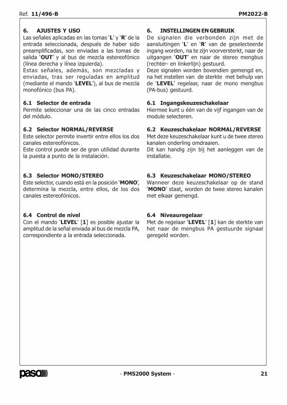
- PMS2000 System -4
Fig. 2.1
A
B
C
Fig. 3.1
- PMS2000 System - 21
6. AJUSTES Y USOLas señales aplicadas en las tomas ‘L’ y ‘R’ de laentrada seleccionada, después de haber sidopreamplificadas, son enviadas a las tomas desalida ‘OUT’ y al bus de mezcla estereofónico(línea derecha y línea izquierda).Estas señales, además, son mezcladas yenviadas, tras ser reguladas en amplitud(mediante el mando ‘LEVEL’), al bus de mezclamonofónico (bus PA).
6.1 Selector de entradaPermite seleccionar una de las cinco entradasdel módulo.
6.2 Selector NORMAL/REVERSEEste selector permite invertir entre ellos los doscanales estereofónicos.Este control puede ser de gran utilidad durantela puesta a punto de la instalación.
6.3 Selector MONO/STEREOEste selector, cuando está en la posición ‘MONO’,determina la mezcla, entre ellos, de los doscanales estereofónicos.
6.4 Control de nivelCon el mando ‘LEVEL’ [1] es posible ajustar laamplitud de la señal enviada al bus de mezcla PA,correspondiente a la entrada seleccionada.
6. INSTELLINGEN EN GEBRUIKDe signalen die verbonden zijn met deaansluitingen ‘L’ en ‘R’ van de geselecteerdeingang worden, na te zijn voorversterkt, naar deuitgangen ‘OUT’ en naar de stereo mengbus(rechter- en linkerlijn) gestuurd.Deze signalen worden bovendien gemengd en,na het instellen van de sterkte met behulp vande ‘LEVEL’ regelaar, naar de mono mengbus(PA-bus) gestuurd.
6.1 IngangskeuzeschakelaarHiermee kunt u één van de vijf ingangen van demodule selecteren.
6.2 Keuzeschakelaar NORMAL/REVERSEMet deze keuzeschakelaar kunt u de twee stereokanalen onderling omdraaien.Dit kan handig zijn bij het aanleggen van deinstallatie.
6.3 Keuzeschakelaar MONO/STEREOWanneer deze keuzeschakelaar op de stand‘MONO’ staat, worden de twee stereo kanalenmet elkaar gemengd.
6.4 NiveauregelaarMet de regelaar ‘LEVEL’ [1] kan de sterkte vanhet naar de mengbus PA gestuurde signaalgeregeld worden.
Ref. 11/496-B PM2022-B Ref. 11/496-B PM2022-B
LEVEL
NORMAL / REVERSE
SELECTOR
TUNER
CD
TAPE IN
AUX 1
AUX 2
OUT
MONO / STEREO
SELECTOR
MUTINGDEVICE
MUTINGDEVICE
SUMMINGSTAGE
AMPLIFIERSTAGES
MUTE IN
PA BUS IN
PA BUS OUT
LEFT BUS
RIGHT BUS
MUTE OUT
MODULE
MULTIPOLE
CONNECTOR
P102
CN102
P103
INPUTSELECTOR
CN104
CN103
CN
106
CN
107
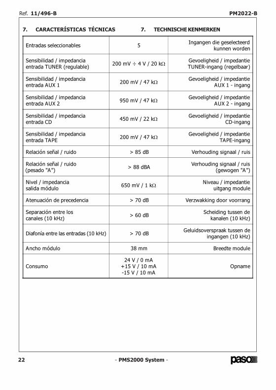
- PMS2000 System - 3
2. CONSIDERAZIONI GENERALIIl modulo ingressi ausiliari permette di collegareal sistema sorgenti audio musicali, sia di tipostereofonico che di t ipo monofonico,caratterizzate da un alto livello di uscita.É possibile selezionare, tramite un commutatorerotativo, fino a cinque differenti sorgentiapplicate ai relativi ingressi.Questo modulo dispone di:• regolazione di sensibilità per l'ingresso
‘TUNER’;• commutatore ‘STEREO/MONO’;• commutatore per l'inversione dei canali
‘SINISTRO/DESTRO’;• controllo di livello del segnale ‘PA’.In fig. 2.1 è riportato lo schema a blocchi delmodulo.
2. GENERAL CONSIDERATIONSThe auxiliary input module can be used to connectmusic audio sources, both stereo and mono,featuring high output levels to the system.It is possible to select up to five different sourcesapplied to the related inputs.They are selected by means of a rotary switch.
This module has the following:• sensitivity adjustment for the ‘TUNER’
input;• ‘STEREO/MONO’ switch;• switch for reversing the ‘LEFT/RIGHT’
channels;• ‘PA’ signal level control.Figure 2.1 shows the block diagram of themodule.
3. IMPOSTAZIONI DI FUNZIONAMENTO3.1 Sensibilità ingresso tunerLa sensibilità di ognuno dei due canali (canalesinistro e canale destro) dell'ingresso ‘TUNER’può essere adattata con precisione al livello delsegnale di uscita della sorgente ad esso applicata.
Per regolare la sensibilità del canale destrooccorrerà agire, per mezzo di piccolo giravite alame piatta, sul trimmer P103 (particolare [A]di fig. 3.1); ruotando il cursore del trimmer insenso orario la sensibilità aumenta, ruotandoloin senso antiorario la sensibilità diminuisce.
Per regolare la sensibilità del canale sinistrooccorrerà agire sul trimmer P102 (particolare[B] di fig. 3.1) analogamente a quanto descrittoper il canale destro.
Effettuando la regolazione della sensibilitàoccorrerà prestare particolare cura affinché ilbilanciamento tra i due canali risulti corretto(situazione verificabile, all'occorrenza, all'uscitadiretta del modulo).
3. OPERATIONAL SETTINGS3.1 Tuner input sensitivityThe sensitivity of each of the two channels (leftchannel and right channel) of the ‘TUNER’ inputcan be adapted precisely to the level of theoutput signal from the source applied to it.
To adjust the sensitivity of the right-handchannel, it is necessary to turn trimmer P103(detail [A] in Figure 3.1) using a small flat-bladed screwdriver. If the cursor of the trimmeris turned in a clockwise direction, the sensitivitywill increase. If it is turned in an anti-clockwisedirection the sensitivity will decrease.
To adjust the sensitivity of the left-hand channel,it is necessary to turn trimmer P102 (detail [B]in Figure 3.1), in a manner similar to thatdescribed for the right-hand channel.
When adjusting the sensitivity, special attentionshould be paid to achieving the correct balancebetween the two channels (this can be checked,if required, on the direct output from themodule).
- PMS2000 System -22
7. CARACTERÍSTICAS TÉCNICAS 7. TECHNISCHE KENMERKEN
Entradas seleccionables 5 Ingangen die geselecteerdkunnen worden
Sensibilidad / impedancia entrada TUNER (regulable) 200 mV ÷ 4 V / 20 kΩ Gevoeligheid / impedantie
TUNER-ingang (regelbaar)
Sensibilidad / impedanciaentrada AUX 1 200 mV / 47 kΩ Gevoeligheid / impedantie
AUX 1 - ingang
Sensibilidad / impedancia entrada AUX 2 950 mV / 47 kΩ Gevoeligheid / impedantie
AUX 2 - ingang
Sensibilidad / impedancia entrada CD 450 mV / 22 kΩ Gevoeligheid / impedantie
CD-ingang
Sensibilidad / impedancia entrada TAPE 200 mV / 47 kΩ Gevoeligheid / impedantie
TAPE-ingang
Relación señal / ruido > 85 dB Verhouding signaal / ruis
Relación señal / ruido(pesado "A") > 88 dBA Verhouding signaal / ruis
(gewogen "A")
Nivel / impedanciasalida módulo 650 mV / 1 kΩ Niveau / impedantie
uitgang module
Atenuación de precedencia > 70 dB Verzwakking door voorrang
Separación entre loscanales (10 kHz) > 60 dB Scheiding tussen de
kanalen (10 kHz)
Diafonía entre las entradas (10 kHz) > 70 dB Geluidsoverspraak tussen deingangen (10 kHz)
Ancho módulo 38 mm Breedte module
Consumo24 V / 0 mA
+15 V / 10 mA-15 V / 10 mA
Opname
Ref. 11/496-B PM2022-B Ref. 11/496-B PM2022-B
- PMS2000 System -2
1.1 Descrizione pannello frontale[1] Controllo di livello.[2] Selettore di ingresso.[3] Selettore inversione canali stereofonici.[4] Selettore miscelazione canali stereofonici.
1.1 Front panel description[1] Level control.[2] Input selector.[3] Stereo channel reversal selector.[4] Stereo channel mixing selector.
1.2 Descrizione pannello posteriore[5] Prese di ingresso TUNER.[6] Prese di ingresso CD.[7] Prese di ingresso TAPE.[8] Prese di ingresso AUX 1.[9] Prese di ingresso AUX 2.[10] Prese di uscita.
1.2 Rear panel description[5] TUNER input sockets.[6] CD input sockets.[7] TAPE input sockets.[8] AUX 1 input sockets.[9] AUX 2 input sockets.[10] Output sockets.
1. GENERAL DESCRIPTION1. DESCRIZIONE GENERALE
- PMS2000 System - 23
Ref. 11/496-B PM2022-B Ref. 11/496-B PM2022-B
1 - PMS2000 System -
INTRODUZIONENel ringraziarVi per aver scelto un prodottoPASO, vogliamo ricordarVi che la nostra aziendaopera con sistema di qualità certificato. Tutti inostri prodotti vengono pertanto controllati inogni fase della produzione per garantirVi lapiena soddisfazione del Vostro acquisto. Per ognievenienza la garanzia coprirà, nell’anno divalidità, eventuali difetti di fabbricazione.Vi raccomandiamo di leggere attentamente leseguenti istruzioni d’uso per sfruttare appienole prestazioni offerte da questo prodotto e perevitare eventuali problemi.
INTRODUCTIONWhile thanking you for having chosen a PASOproduct, we would like to remind you that ourcompany works according to a certified QualitySystem. This means that all our products arechecked during every phase of manufacturingin order to guarantee that you will be fullysatisfied with your purchase. At all events, theguarantee will cover any manufacturing flawsfor the whole year for which it is valid. Werecommend that you read the fol lowinginstructions for use carefully in order to exploitin full the performance of this product and toavoid any problems.
NOTANel continuo intento di migliorare i propri prodotti,la PASO S.p.A. si riserva il diritto di apportaremodifiche ai disegni e alle caratteristiche tecnichein qualsiasi momento e senza alcun preavviso.
NOTEPASO S.p.A. strive to improve their productscontinuously, and therefore reserve the right tomake changes to the drawings and technicalspecifications at any time and without notice.
Istruzioni per l’usoInstructions for useManuel d'utilisation
GebrauchsanleitungGebruiksaanwijzing
Instrucciones de empleo
SISTEMA MODULARE PROFESSIONALE PMS2000PMS2000 PROFESSIONAL MODULAR SYSTEM
Modulo ingressi ausiliariAuxiliary inputs module PM2022-BModule d'entrées auxiliairesHilfseingangsmodulMódulo entradas auxiliaresModule hulpingangen
- PMS2000 System -
Ref. 11/496-B PM2022-B
24
Via Mecenate, 90 - 20138 MILANO - ITALIATEL. +39-02-580 77 1 (15 linee r.a.)
FAX +39-02-580 77 277http://www.paso.it
Printed in Italy - 01/05 - 0.1K - 11/496-B
S.p.A
NOTALa PASO declina ogni responsabilità per danni a cose e/o persone derivanti dall'uso noncorretto dell'apparecchio o da procedure non rispondenti a quanto riportato sul presentelibretto.
NOTEPASO will not accept any liability for damage to property and/or persons arising out ofincorrect use of the equipment or of procedures that do not comply with the instructionsprovided in this booklet.
NOTEPASO décline toute responsabilité en cas de dommages matériels et/ou physiques provoquéspar l'utilisation impropre de l'appareil ou encore par des opérations ou des interventions nerespectant pas les instructions figurant dans la présente notice.
MERKEPASO lehnt jede Haftung für Schäden an Personen und / oder Gegenständen ab, die durchunzweckmäßige Verwendung oder Vorgehen entstehen, die nicht den Anweisungen diesesHandbuches entsprechen.
OPMERKINGPASO kan niet aansprakelijk worden gesteld voor schade aan voorwerpen en/of persoonlijkletsel die het gevolg zijn van een onjuist gebruik van het apparaat of van procedures die nietovereenkomen met de voorschriften uit deze handleiding.
NOTALa PASO rehusa cualquier responsabilidad ante daños a cosas y/o personas causados por unautilización no correcta del aparato o por operaciones no conformes a cuanto indicado en estefolleto.