MEMBRANE ULTRAFILTRAZIONE - Hytek
20
MEMBRANE ULTRAFILTRAZIONE 25 ULTRAFILTRATION MEMBRANES
Transcript of MEMBRANE ULTRAFILTRAZIONE - Hytek

MEMBRANE ULTRAFILTRAZIONE
25
ULTRAFILTRATION MEMBRANES


ww
w.h
yte
kin
tl.c
om
in
fo@
hy
tek
intl
.co
m
ULTRAFILTRAZIONE / ULTRAFILTRATION
UF
1. BREVE INTRODUZIONE DELL ’ ULTRAFILTRAZIONELa tecnologia di ultrafiltrazione ha avuto notevoli progressi negli ultimi trent’anni. L’ultrafiltrazione non è solo usata specificatamente nella separazione di specie liquide, ma ha sempre più vaste applicazioni nel trattamento industriale delle acque. Questa tecnologia può essere usata come pre-trattamento nella dissalazione e nella produzione di acqua pura ed ultrapura per garantire elevate performances all’osmosi inversa e stabilità a lungo tempo delle acque. L’ultrafiltrazione, dato che rimuove impurità quali materiali in sospensione, colloidi e batteri, e che mantiene gli elementi minerali che sono utili al consumo umano, trova larga applicazione nella produzione di bevande e acque minerali. Le membrane di ultrafiltrazione nella tecnologia delle membrane devono le loro proprietà alla struttura anisotropa porosa. Basata sulla teoria del setaccio meccanico, l’ultrafiltrazione utilizza la differente pressione sui due lati della membrana per separare la parte liquida. La pressione normalmente applicata è di 0,03 e 0,6 MPa; i diametri medi dei pori variano dagli 0,005 allo 0,1 microns ; il peso molecolare medio del trattenuto varia dai 1000 ai 500000 Dalton.
1.1 PECULIARITA’ DELLA SEPARAZIONE DI UF (1) Durante il processo di separazione non accade nessun cambio ionico e il processo richiede poca pressione. (2) Può operare a temperature normali, quindi è adatta per la purificazione e la concentrazione di alcuni prodotti termosensibili come i succhi di frutta, le biomasse e alcune specie farmaceutiche.(3) L’ultrafiltrazione è un processo guidato da basse pressioni; l’equipaggiamento necessario è quindi facile da gestire e mantenere.(4) Trova applicazione in un ampio spettro di utilizzi. Questa
UF
1. BRIEF INTRODUCTION OF UF The UF technology has improved greatly in the recent 30 years. The UF does not specifically used in the separation of special liquor only; it has wider and wider application capability in industrial water treatment. The UF can be used as pre-t reatment faci l i ty in desal in izat ion and the pure and ult ra pure water production to ensure the long-time stability and secure performance of RO and other facilities that will be used later. As the UF only remove the impurities like suspension, colloids and bacteria, and still keep the mineral elements that are useful to human body, it is especially useful in drinks and mineral water producing. As a kind of IMT technology, UF membrane appl ies porous an i sot rop ic s t ructure. Based on mechanical sieve theory˜the UF use the different pressure on the two membrane sides to separate the liquor. The pressure usually applies 0.03~0.6 MPa, sieve pore diameter in the range of 0.005µm to 0.1µm, and withholding molecular amount is around 1000~500,000 Dalton.
1.1 THE PECULIARITIES OF UF SEPARATION (1) No relative changes happened during the separate process and it needs the least power to operate; (2) It can be operated under normal temperature; therefore it is suitable for the purification and concentration of some thermal sensitive material such as fruit juice, biomass and some pharmaceuticals; (3) The UF is low pressure-driven, and the equipment and the process i s easy to operate, manage and maintain; (4) It can be used in wide range of areas. The UF technique is
IntroduzioneIntroduction
792
UltrafiltrazioneUltrafiltration

ww
w.h
yte
kin
tl.c
om
in
fo@
hy
tek
intl
.co
m
tecnica può essere utilizzata per quei soluti aventi un peso molecolare nel range 1000 – 500000 Dalton, o che hanno misure nel range 0,005 – 0,1 micron. Inoltre, l’uso di differenti serie di membrane può portare a filtrati di differente taglio molecolare. 1 . 2 D I F F E R E N Z A T R A U F E G E N E R I C A FILTRAZIONE/MICROFILTRAZIONE (1) Le membrane di UF hanno il diametro nominale del poro più piccolo per la rimozione dei batteri, dei pirogeni, virus, colloidi, proteine e macromolecole. (2) La capacità di separare le differenti specie non dipende solo dal diametro, dalla misura e forma del poro della membrana; essa dipende anche dalle proprietà chimiche del solvente, dei soluti e dalla struttura esterna del piano di contatto. (3) L’intero processo è dinamico e quindi la velocità di filtrazione è difficile da tenere costante a causa dello strato di soluto trattenuto sulla membrana. Questo tipo di separazione è principalmente dipendente dal carattere poroso della membrana, dall’assorbimento della membrana, dalla reiezione, dalle proprietà di intasamento ed efficienza separativa alle grosse molecole.2. ELEMENTI CHE POSSONO INCIDERE SUL PROCESSO DI UF 2.1 MATERIALE DELLE MEMBRANE DI UF (STABILITA’ CHIMICA, IDROFILICITA’, ECC.) Materiali polimerici comuni usati nell’UF includono: polivinildenfluoruro (PVDF), polieteresulfone (PES), polipropilene (PP), polietilene (PE), polisulfone (PS), poliacrilonitrile (PAN), polivinilcloruro (PVC). Il polieteresulfone è stato tra i primi materiali impiegati fin dagli inizi degli anni 90. Alla fine degli anni 90 è diventato molto comune nell’industria del trattamento acque il PVDF. Questi due materiali rappresentano al momento quelli maggiormente usati per le membrane di ultrafiltrazione. 2.2 STRAORDINARIA CAPACITA’ ANTIOSSIDANTE DEL PVDF La stabilità chimica e l’idrofilicità sono le due più importanti proprietà dei materiali caratterizzanti le membrane di ultrafiltrazione e microfiltrazione. La stabilità chimica determina la vita effettiva di lavoro sotto le condizioni acido-base, ossidanti e microorganiche , e determina anche il metodo di pulizia. L’idrofilicità determina il grado di assorbimento della membrana e corrispondentemente determina il flusso della membrana. 1) STABILITA’ CHIMICA Il PVDF ha la miglior stabilità chimica, e la sua resistenza (per esempio all’ NaClO) è quasi 10 volte superiore al PES e PS. Dato che la pulizia con ossidanti è il modo più efficiente di pulire le membrane dal biofouling e prevenire l’intasamento, ne consegue che le proprietà del PVDF lo pongono in una posizione primaria tra i materiali.
Forza longitudinale
applicable to the solutes that whether has the molecular weight in the range of 1000~500,000 Dalton, or has the size in the range of 0.005~0.1µm. Moreover, use different series of membrane can group the solute in mixing liquor by molecular weight. 1.2 DIFFERENCE BETWEEN UF AND GENERAL FILTRATION / MICROFILTRATION (1) The UF membrane has the smallest nominal pore diameter in the industry allows for the removal of nearly all the bacteria, thermal sources, virus and colloids, protein, macromolecule organic matters. (2) The effect of separate performance is not only depend on the membrane pore diameter and the size, shape and property of solution it also depend on the chemical property of the liquor, the ingredients, and the exterior structure of contact layer the electricity and the chemical property.(3) The whole process is dynamic and no fouling layer therefore the residue left on the membrane surface is restricted enough to keep the filtration velocity steady. This kind of separation is mainly depending on the membrane porous character, the membrane absorption, rejection, blocking property and its screening efficiency to big molecular.2. THE ELEMENTS THAT MAY AFFECT THE UF PROPERTY 2.1 THE CHEMICAL MATERIAL OF UF MEMBRANE (CHEMICAL STABILITY, HYDROPHILICITY ETC.) Common polymeric materials used in UF includes: Polyvinylidenefluoride (PVDF), Polyethersufone (PES), Polypropylene (PP), Polyethylene (PE), Polysulfone (PS), Polyacrylonitrile (PAN), Polyvinyl chloride (PVC). Since the beginning of 1990s, PES has being used in business. At the end of 90s, PVDF UF becomes more popular in the water treatment industry. Therefore, PVDF and PES are the two most widely used UF membrane materials at this stage 2.2 THE EXTRAORDINARY ANTIOXIDANT ABILITY OF PVDF The chemical stability and hydrophilicity are the two most important properties of the materials that make UF and MF. The chemical stability determines the material work life under the co action of acid-base, oxidant and microorganism, and also determines the cleaning method. The hydrophilicity determines the membrane absorption rate, and correspondingly affects the membrane flux. 1) CHEMICAL STABILITY PVDF has the best chemical stability, and its duration to oxidants (e.g. NaClO) is nearly 10 times of the duration of PES and PS. Since oxidants’ cleaning is the most efficient way to clean the microorganisms and organisms from membrane and thus prevent plugging, the excellent anti-oxidants property gives PVDF an irreplaceable position in material world.
Relative longitudinal strength
Tempo (h) di condizionamento a 1500 ppm NaClOTime (h) under 1500 ppm NaClO
IntroduzioneIntroduction
793
UltrafiltrazioneUltrafiltration
ww
w.h
yte
kin
tl.c
om
in
fo@
hy
tek
intl
.co
m
2) IDROFILICITA’ Materiali delle membrane con buona idrofilicità sono più resistenti allo sporcamento o possono essere più facilmente puliti e recuperare velocemente le caratteristiche iniziali. La qualità di idrofilicità è misurata dall’angolo di contatto.
L’angolo di contatto è indicato nella figura; più grande è ϑ, minore è l’idrofilicità. Le sostanze tendono a sporcare maggiormente la membrana per valori di ϑ tendenti a 0.Angolo di contatto per differenti materiali di membrane di UF
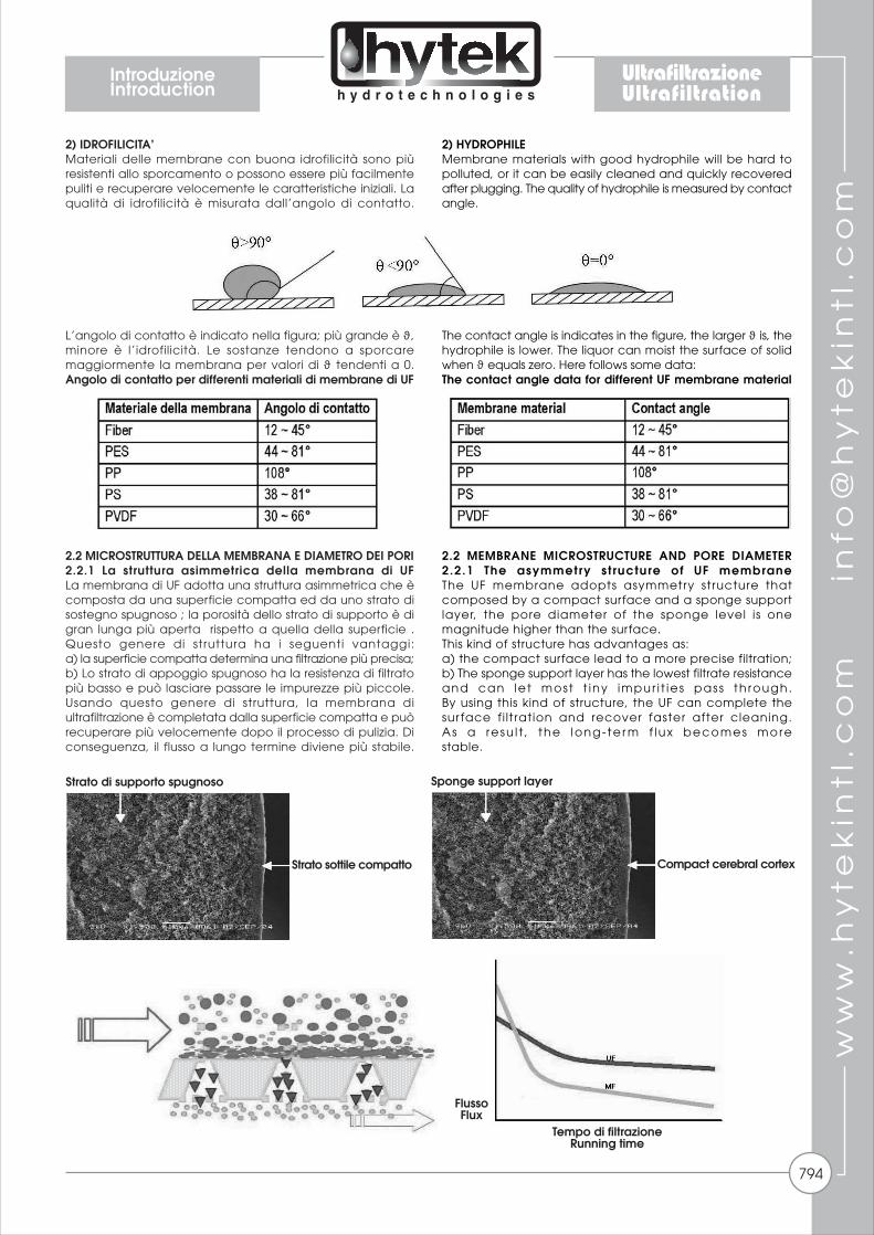
2.2 MICROSTRUTTURA DELLA MEMBRANA E DIAMETRO DEI PORI 2.2.1 La struttura asimmetrica della membrana di UFLa membrana di UF adotta una struttura asimmetrica che è composta da una superficie compatta ed da uno strato di sostegno spugnoso ; la porosità dello strato di supporto è di gran lunga più aperta rispetto a quella della superficie . Questo genere di struttura ha i seguenti vantaggi:a) la superficie compatta determina una filtrazione più precisa; b) Lo strato di appoggio spugnoso ha la resistenza di filtrato più basso e può lasciare passare le impurezze più piccole. Usando questo genere di struttura, la membrana di ultrafiltrazione è completata dalla superficie compatta e può recuperare più velocemente dopo il processo di pulizia. Di conseguenza, il flusso a lungo termine diviene più stabile.
2) HYDROPHILE Membrane materials with good hydrophile will be hard to polluted, or it can be easily cleaned and quickly recovered after plugging. The quality of hydrophile is measured by contact angle.
The contact angle is indicates in the figure, the larger ϑ is, the hydrophile is lower. The liquor can moist the surface of solid when ϑ equals zero. Here follows some data:The contact angle data for different UF membrane material
2.2 MEMBRANE MICROSTRUCTURE AND PORE DIAMETER 2.2.1 The asymmetry st ructure of UF membrane The UF membrane adopts asymmetry structure that composed by a compact surface and a sponge support layer, the pore diameter of the sponge level is one magnitude higher than the surface. This kind of structure has advantages as: a) the compact surface lead to a more precise filtration; b) The sponge support layer has the lowest filtrate resistance and can le t most t iny impur i t ies pass th rough. By using this kind of structure, the UF can complete the sur face fi ltration and recover faster after cleaning. As a resu l t , the long- te r m f lux becomes morestable.
Strato di supporto spugnoso
Strato sottile compatto
FlussoFlux
Tempo di filtrazioneRunning time
Sponge support layer
Compact cerebral cortex
IntroduzioneIntroduction
794
UltrafiltrazioneUltrafiltration
ww
w.h
yte
kin
tl.c
om
in
fo@
hy
tek
intl
.co
m
2.2.2 Il diametro del poro della membrana di UF Il metodo del punto di bolla, che è basato sulla teoria dell’azione capillare, è il metodo più semplice per misurare il diametro dei pori delle membrane di UF. Si ha la seguente formula:
P= (4*δ*cosϑ)/DIn questa formula: - P vuole dire pressione di punto di bolla. Immersa la membrana nell'acqua ed aggiunta pressione ad un lato della membrana, la pressione al momento in cui la bolla esce dall'altro lato della membrana è chiamato pressione di punto di bolla; − δ vuole dire tensione di superficie del liquido (il water)/aria - ϑ vuol dire angolo di contatto del liquido (l'acqua) e il solido (la membrana); - D è il diametro del poro del capillare. Si può notare dalla formula: a) Il metodo di punto di bolla permette di calcolare il massimo diametro del poro della membrana; b) La pressione di punto di bolla è più grande quando D sta diventando più piccolo. In teoria, questa relazione non dipende dal materiale. Questa teoria può essere usata anche nell'ispezione di integrità. Con un lato della membrana immerso nel liquido (l'acqua), compressa aria all'altro lato di membrana, osservando la velocità declinata di pressione d'aria, o se c'è bolla continua uscita dall'altro lato per determinare l'integrità di membrana. Come estensione di questa teoria, il metodo“dell'infiltrazione di aria” può essere usato anche per misurare la distribuzione dei diametri dei pori della membrana. 2.3 STRUTTURA DELLA MEMBRANA DI ULTRAFILTRAZIONE Il disegno di struttura della membrana è il punto chiave tra i caratteri della membrana e i parametri di operazione. La membrana a fibra cava è il tipo estesamente più usato. Gli altri tipi includono il tipo a tubo e a spirale. Quando noi consideriamo la struttura, noi dobbiamo considerare:1) aumentare la densità di membrana e produrre più permeazione per unità; 2) La possibilità di tollerare qualità di acqua di alimentazione peggiore; 3) facilità di pulizia; 4) costo basso. La membrana a fibra cava è il tipo più utilizzato. A seconda di dove è posizionato lo strato compatto, la membrana a fibra cava si divide in tre specie: a filtrazione dall’interno (in-out), a filtrazione dall’esterno (out-in) e ad entrambi i versi di filtrazione. La filtrazione dall’esterno fa si che vi sia dello spazio libero tra le fibre. In questo modo l’acqua di alimento può essere con maggior carico di solidi sospesi e di qualità peggiore. La filtrazione dall’interno richiede una migliore qualità dell’acqua in ingresso per prevenire l’intasamento.2.4 MODI DI FUNZIONAMENTO E PULIZIA 1) Modi di funzionamento Il sistema capillare di ultrafiltrazione ha due modi di funzionamento: la filtrazione Dead-end (a vicolo cieco) e a cross-flow (flusso tangenziale). Nella filtrazione dead-end tutta l’acqua di alimento diventa permeato. Nella filtrazione cross-flow parte dell’acqua di alimento diventa permeato, mentre l’altra diventa concentrato con le impurità. La filtrazione dead-end necessita minor energia e ha una più bassa pressione di lavoro rispetto al modo cross-flow, quindi riduce i costi di gestione. Al contrario, il modo cross-flow permette di trattare acque con un contenuto di solidi sospesi maggiore . Il contenuto dei solidi sospesi determina il modo operativo. A flussi bassi l’inquinante accumulatosi sulla superficie della membrana può essere facilmente rimosso e mantenere il flusso stabile; al contrario, con flussi più elevati, la membrana di ultrafiltrazione è più portata all’intasamento e quindi determinerà una riduzione del livello di rigenerazione dopo lavaggio. Quindi c’è un flusso critico per ogni tipo di acqua in alimento ad una membrana di ultrafiltrazione. Il flusso operativo dovrebbe essere sempre inferiore a questo flusso critico che va determinato operativamente.
2.2.2 The pore diameter of UF membrane The bubble point method, which is based on the capillary action theory, is the simplest method to measure the UF membrane pore diameter. We have the formula as:
P= (4*δ*cosϑ)/D In this formula: - P stands for bubble point pressure. Immerse the membrane into the water and add pressure to one side of the membrane, the pressure at the time when bubble is outlet from the other side of the membrane is called bubble point pressure; - δ stands for the surface tension of liquor (water)/air; - ϑ stands for the contact angle of liquor (water) and solid (membrane); - D is the pore diameter of capillary. It may be noticed from the formula: a) The bubble point method gained the max membrane pore diameter; b) The bubble point pressure is greater when D is getting smaller. In theory, this relationship is not depends on the material. This theory can also be used in the integrity inspection. With one side of the membrane immersed in the liquor (water), compress air to the other side of membrane, by observing the declined velocity of air pressure, or whether there are continuous bubble come out from the other side to determine the integrity of membrane. As an extension of this theory, the “air infiltration” method can also be used to measure the membrane pore diameter distribution. 2.3 UF MEMBRANE STRUCTURE The membrane structure design is the key point between membrane characters and operation parameters. The hollow fiber membrane is the most widely used style at this stage. The other styles include pipe style and spiral style. When we consider of structure, we need to think about: 1) Raise the membrane density and produce more permeate per unit; 2 ) C a n t o l e r a n t t h e re l a t i v e l y w o r s t f e e d w a t e r qual i ty; 3) Easy to clean; 4) Low cost. The hollow fiber membrane is the most popular membrane style. According to the different compact level site, the hollow fiber membrane is divided to three species: the inner pressure, outside pressure and inner & outside pressure membranes. The feed water flow between the membrane and give a free space for membrane. Thus, it can bare the feed water with high suspension load and worse quality; the feed water flow in the hollow fiber lumen of inner pressure membrane, thus it requires the better feed water to prevent plugging. 2.4 OPERATING AND CLEANING 1) F low des ign The capi l lary UF system appl ies two pr imary f low des igns : the Dead-end f i l t ra t ion and cross - f low mode. The feed water a l l become per meate af ter dead-end f i l t rat ion. But after cross- f low f i l t rat ion, part of t h e f e e d b e c o m e p e r m e a t e , t h e o t h e r b e c o m e concent rate water w i th impur i t ies . Dead-end f i l t rat ion uses less energy and has a lower o p e r a t i n g p r e s s u r e t h a n c r o s s - f l o w t h e r e f o r e reducing operat ing costs . A l ternat ive ly , cross - f low can handle h igher so l ids loading. T h e s u s p e n s i o n r e q u i r e m e n t d i c t a t e s t h e f l o w d e s i g n . U n d e r l o w e r f l u x , t h e p o l l u t a n t c a n b e eas i ly removed and than keep the f lux s teady; on the cont rary , under h igher f lux , the UF membrane i s more prone to p lugg ing and thus w i l l lower the resumpt ion leve l . The re fo re , the re i s a c r i t i ca l UF f l ux fo r d i f fe ren t water ; the operat ing f lux shou ld a lways under th i s c r i t i c a l f l u x t h a t h a s b e e n d e t e r m i n e d b y t e s t .
IntroduzioneIntroduction
795
UltrafiltrazioneUltrafiltration

ww
w.h
yte
kin
tl.c
om
in
fo@
hy
tek
intl
.co
m
2) Metodi di pulizia I metodi di pulizia dell’UF includono il flussaggio in equicorrente, il controlavaggio, la pulizia con aria, il flussaggio con aggiunta di chemicals ed il lavaggio chimico. Il flussaggio in equicorrente ed il controlavaggio possono rimuovere lo strato di sporco sulla superficie della membrana, mentre la pulizia con aria miscelata all’acqua distacca più efficacemente gli inquinanti. Il flussaggio con aggiunta di chemicals ed il lavaggio chimico utilizzano agenti chimici per rimuovere colloidi, microrganismi, sali inorganici che intasano la membrana di UF internamente. L’efficienza di lavaggio può essere innalzata aumentando la frequenza di lavaggio e la forza.
3. GLOSSARIO TECNICO Membrana anisotropa Questa membrana a fibra cava formata per polimerizzazione, che è formata da uno strato sottile e da un supporto spugnoso più profondo. Alimento L’acqua che alimenta i l sistema di ultrafi ltrazione. Permeato In condizioni di lavoro ordinario, la quantità d’acqua che passa attraverso la membrana e non ha colloidi, particelle e microrganismi. Flusso La velocità con la quale il permeato passa attraverso la membrana. Normalmente è indicato come la quantità di permeato nell’unità di tempo per unità di area. Viene usualmente indicato in L/m2 h. Pressione Trasmembrana Indicata in TMP, è la differenza tra la pressione media del lato alimento ed il lato permeato. TMP = (pressione di ingresso + pressione di uscita concentrato)/2 - (pressione di uscita permeato) Nella filtrazione Dead-end: TMP = pressione di ingresso – pressione di uscita permeato Controlavaggio
2) Cleaning methods The UF cleaning method include fore flush, back flush, air scrub, diffuse chemically wash and chemical cleaning. The fore and back flush can remove the fouling layer on the surface of membrane, while the air scrub using the rush air and water mix liquor to more effectively remove the pollutant. The diffuse chemically wash and chemical cleaning using chemical reagent to remove the colloids, organism, inorganic salt plugging in/outside of UF membrane˜We can raise the cleaning efficiency by raise the cleaning frequency and strength.
3. TECHNICAL GLOSSARY Anisotropic Membrane This artificial polymerize hollow fiber, which is made up by an even and compress, thin surface and support sponge inner, is the actual prohibiting level to the pollutants; Feed The water feed into the UF system; Permeate Under ordinary working condition, the water that had passes through the membrane and has no colloids, particles and microorganism; Flux The velocity of permeate pass the membrane. Usually it is shown as the permeate amount in unit time and unit of area. We usually use the units as L/m2.h. Trans-membrane Pressure Simplified as TMP, is the difference between the average pressure of Feed side and the Permeate side. TMP = (inlet pressure + concentrate output pressure)/2 - (Permeate output) During Dead-end filtration: TMP = inlet pressure – Permeate output pressure; Backwash
IntroduzioneIntroduction
796
UltrafiltrazioneUltrafiltration

ww
w.h
yte
kin
tl.c
om
in
fo@
hy
tek
intl
.co
m
Dal lato del permeato, si fa passare acqua con le stesse o migliori caratteristiche del permeto, invertendo il flusso di filtrazione ed uscendo dal lato dell’ingresso. Dato che si va nella direzione opposta a quella di filtrazione, l’acqua porta via gli agenti inquinanti che si sono accumulati sulla superficie della membrana. Pulizia con aria Si invia aria compressa attraverso l’ingresso e miscelata con l’acqua contribuisce alla rimozione dello sporco dalla superficie della membrana. Flussaggio con aggiunta di chemicals Vengono aggiunti specifici reagenti chimici all’acqua in ingresso, tramite un modo a ricircolo o a bagno per eliminare gli agenti intasanti sulla superficie della membrana. Recupero La percentuale di permeato rispetto all’acqua in ingresso. Recupero% = (Permeato/Alimento) * 1004. MEMBRANE CAPILLARI4.1 MEMBRANA OMEXELL La membrana OMEXELL è una membrana a fibra cava a doppio strato che utilizza il PVDF come materiale di base. Questo materiale può tollerare alti livelli di disinfettanti come il perossido o l’ipoclorito per rimuovere la lo sporcamente di tipo biologico. La membrana OMEXELL ha il più piccolo diametro nominale del poro del mercato per questo genere di materiale, permettendo la rimozione di tutto il articolato, batteri e la gran parte di visus e colloidi.Nonostante il diametro piccolo del poro, la membrana ha un’alta porosità determinando dei flussi simili a quelli ottenibili con la microfiltrazione che in molti casi può sostituire. Il sistema di UF OMEXELL è disegnato in una configurazione out/in del flusso che permette minori intasamenti, più elevati carichi di solidi in ingresso, una più elevata area di filtrazione ed una semplice pulizia. Principalmente il sistema viene fatto lavorare in dead end (canale cieco), ma il modulo può essere adattato facilmente al modo cross-flow (flusso tangenziale). La filtrazione Dead end richiede minor energia ed ha una minor pressione operativa rispetto al sistema cross-flow, riducendo i costi. Al contrario il modo cross-flow permette di trattare più elevati carichi di solidi sospesi. Il contenuto di solidi sospesi definirà il modo operativo. Normalmente queste membrane di UF lavorano a flussi di permeato costanti. La pressione trasmembrana (TMP) salirà naturalmente nel tempo ed il modulo dovrà essere periodicamente controlavato o flussato con aria per rimuovere lo strato di concentrato accumulatosi sulla membrana. Diversi disinfettanti ed agenti pulenti possono essere usati per rigenerare la membrana.
From the permeate side, fill in the water that has the same or better level as permeate water, flush the hollow fiber membrane and let the water flow out from the inlet side. Since it uses the opposite direction of the filtration process, the water can destroy and wash the plugging on the membrane surface; Air-wash By sending the compress air through the inlet side, through the mixture shake of compressed air and water to destroy and wash the plugging on the membrane surface; Diffuse Chemically Wash To add specific chemical reagent to the Feed water side, through recycle flow, soak, to destroy and wash the plugging on the membrane surface; Recovery The percentage of permeate to feed water. Recovery % = (Permeate / Feed) * 100.4. CAPILLAR MEMBRANES 4.1 OMEXELL MEMBRANE The OMEXELL UF double-walled hollow fiber membrane utilizes PVDF based materials. The membranes can tolerant strong levels of disinfectants such as peroxide or hypochlorite to sufficiently remove bacterial growth. The OMEXELL UF PVDF membrane has the smallest nominal pore diameter in the industry (for PVDF material) allowing for the removal of all particulate matter, bacteria and most viruses and colloids. Despite the small pore diameter, the membrane has a very high porosity resulting in a flux similar to that of microfiltration (MF) and can effectively replace MF in most cases. The Omexell UF system is designed with an outside/in flow configuration which allows for less plugging, higher solids loading, higher flow area and easy cleaning. The primary flow design is deadend filtration but the module can easily be adapted to a crossflow mode.Deadend filtration uses less energy and has a lower operating pressure then crossflow therefore reducing operating costs. Alternatively, crossflow can handle higher solids loading. The solids handling requirement will dictate the flow design. Typically, Omexell UF is operated at a constant permeate flow. The transmembrane pressure (TMP) will naturally increase over time and the module can be periodically back flushed or air scrubbed to remove the fouling layer. Disinfectants and other cleaning agents can be used to fully remove and prevent biological growth aswell as other foulants.
Membrana a fibra cavaHollow fiber membrane
IntroduzioneIntroduction
797
UltrafiltrazioneUltrafiltration

ww
w.h
yte
kin
tl.c
om
in
fo@
hy
tek
intl
.co
m
4.2 MODULI E PARAMETRI BASE 4.2 MODULES AND PARAMETERS
Qualità dell’acqua richiesta da sistemi di UF in/out ed out/in The water quality required by outside flow and in flow UF
CaratteristicheCharacteristics
798
UltrafiltrazioneUltrafiltration

ww
w.h
yte
kin
tl.c
om
in
fo@
hy
tek
intl
.co
m
4.3 DISEGNI DIMENSIONALI
MODULI/MODULES SFX 26XX
MISURE IN mm/PARAMETERS (mm)
MODULI/MODULES SFX 28XX
MISURE IN mm/PARAMETERS (mm)
4.3 THE APPEARANCE AND CONNECTOR SIZE
124.
5
Ø 1
65
Permeato/Permeate DN50 Alimento/Feed DN50
Concentrato/Concentrate DN50
LL3L2L1
LL3L2
L1
180
Ø 2
25
Permeato/Permeate DN50 Alimento/Feed DN50
Concentrato/Concentrate DN40
MODULO/MODULES
SFX-2640SFX-2660SFX-2680
135618562356
100015002000
111016102110
121017102210
L L1 L2 L3
MODULO/MODULES
SFX-2860SFX-2880
18602360
15002000
16202120
18102310
L L1 L2 L3
CaratteristicheCharacteristics
799
UltrafiltrazioneUltrafiltration
ww
w.h
yte
kin
tl.c
om
in
fo@
hy
tek
intl
.co
m
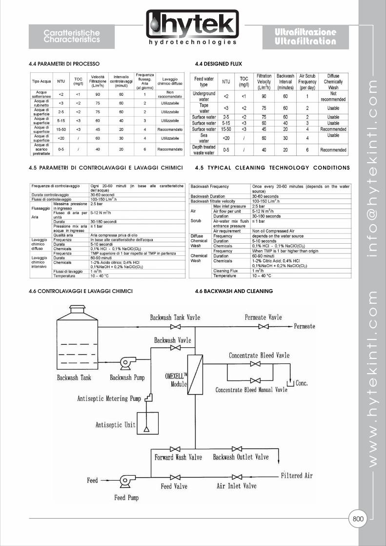
4.4 PARAMETRI DI PROCESSO
4.5 PARAMETRI DI CONTROLAVAGGI E LAVAGGI CHIMICI
4.6 CONTROLAVAGGI E LAVAGGI CHIMICI
4.4 DESIGNED FLUX
4.5 TYPICAL CLEANING TECHNOLOGY CONDITIONS
4.6 BACKWASH AND CLEANING
CaratteristicheCharacteristics
800
UltrafiltrazioneUltrafiltration
ww
w.h
yte
kin
tl.c
om
in
fo@
hy
tek
intl
.co
m
I controlavaggi, i lavaggi chimici diffusi, i lavaggi chimici intensivi ed i sistemi di flussaggio aria sono necessari per tenere i sistemi di Ultrafiltrazione stabili. 4.6.1 Sistema di controlavaggio Il sistema è formato da un serbatoio di controlavaggio, pompa di controlavaggio e stazione di dosaggio NaClO. Serbatoio di controlavaggio Dato che viene usato permeato dell’UF durante il controlavaggio, il serbatoio di raccolta del permeato funge anche da serbatoio di controlavaggio Pompa di controlavaggio La pompa di controlavaggio è richiesta durante i frequenti controlavaggi ed i parametri della pompa possono essere scelti in accordo ai seguenti elementi: - 1) Flusso: Vengono usati 100-150 L/m2.h - 2) Pressione: 1-2 bar -3) La pompa dovrebbe essere in acciaio inox Stazione di dosaggio NaClO Può essere aggiunto NaClO nell’acqua di controlavaggio per aumentare l’effetto controlavante e l’efficienza di rimozione batterica. 4.6.2 Sistema di lavaggio chimico diffuso Il sistema di lavaggio chimico diffuso è raccomandato per acque in ingresso di bassa qualità ed è composto da un sistema di dosaggio.Sistema di lavaggio acidoSi raccomanda di aggiungere una soluzione acida durante il lavaggio chimico diffuso per eliminare l’inquinamento di tipo inorganico. L’acido può essere scelto tra HCl, acido ossalico, acido citrico in accordo alla qualità dell’acqua in ingresso. Sistema di lavaggio basico Si raccomanda di aggiungere una soluzione basica durante il lavaggio chimico diffuso per eliminare l’inquinamento di tipo organico. Si raccomanda di usare 0,1% NaClO + 0,05 NaOH. 4.6.3 Sistema di lavaggio chimico intensivo Il sistema di lavaggio chimico intensivo è usato se la TMP è di 1 bar superiore alla situazione iniziale ed il controlavaggio non da risultati. Il sistema include un serbatoio per la soluzione chimica, una pompa per il ricircolo ed un filtro di pulizia. 4.6.4 Sistema di flussaggio aria Il sistema di flussaggio aria può aumentare l’efficienza del controlavaggio e essa richiede aria compressa priva di olio. La pressione massima in ingresso è 2,5 bar, la massima quantità di aria è 5-12 Nm3/h.5. MEMBRANE TUBOLARI 5.1 MEMBRANA COMPACT 38PRVF/GRH La membrana tubolare COMPACT 38PRV/GRH presenta elevate capacità di filtrazione per acque di scarico e di concentrazione in processi difficili. Le membrane COMPACT 38PRV/GRH possono trattare alte concentrazioni di solidi sospesi in modo semplice, permettendo il passaggio anche di grosse particelle senza intasare il sistema. Il materiale del tubolare è PVDF che permette di trattare svariati tipi di scarichi e consente il lavaggio con gran parte dei prodotti chimici ossidanti presenti sul mercato. Il diametro dei tubolari può essere di 5,2 mm ed 8 mm, permettendo l’ottimizzazione in base al processo. Il sistema tubolare COMPACT viene utilizzato nella modalità cross-flow (flusso tangenziale) e trova grande applicazione nei sistemi MBR (Membrane Biological Reactor). I moduli disponibili possono essere forniti con corpo in PVC o per le applicazioni più estreme,in vetroresina.
Backwash, diffuse chemical wash (at will), cleaning and air compress systems are necessary to keep the UF system’s stable operation. 4.6.1 Backwash System The system is made up by backwash tank, backwash pump and NaCIO dose equipment. Backwash Water Tank Since we use UF permeate during backwash, we can use the permeate tank can be used as backwash tank. Backwash Pump The backwash pump is required during frequent backwash and the pump parameters can be chosen according to the following elements: - 1) Flux: we use 100 ~ 150L/m2.h t - 2) Lifts˜10 ~ 20 m H2O; - 3) The pump should use stainless steel as flowing part material. NaCIO Equipment We can add NaCIO in the backwash water to ra ise t h e b a c k w a s h e f f e c t a n d b a c t e r i a r e m o v e eff ic iency. 4.6.2 Diffuse Chemical Wash SystemThe diffuse chemical wash system is recommended for low-quality feed water and it is compounded by dosing pump and metering pump. Acid Wash Dosing Pump Equipment It is recommended to add acid solution during the diffuse chemical wash to avoid inorganic pollution. The acid can be chosen from HCI, oxalic acid or citric acid according to the feed quality. Base Wash Dosing Pump Equipment It is recommended to add base solution during the diffuse chemical wash to avoid organic pollution. We recommend using 0.1% NaCIO + 0.05% NaOH. 4.6.3 Chemical Wash System The chemical wash system is used if the TMP is 1.0 bar higher than original TMP, and backwash has no use. The chemical wash system includes solution tank, cleaning liquor pump and cleaning filter. 4.6.4 Air Compress System Air scrub can raise the backwash eff ic iency, and i t requires non-oil compress air, maximum inlet pressure i s 2 . 5 b a r, m a x i m u m i n l e t a i r a m o u n t i s 5 – 1 2 Nm3/h.5. TUBULAR MEMBRANES 5.1 COMPACT MEMBRANE 38PRVF/GRH The tubular membrane COMPACT 38PRVF/GRH provides excellent capabilities for filtering and concentrating difficult process and waste streams. It can handle high concentrations of suspended solids with ease, allowing the passage of even large solids without plugging the UF system. The tubular material is PVDF and it allows to treat different types of wastes and it can be cleaned with most of the chemical oxidant products on the market. The tubulars can be supplied with 5,2 mm and 8 mm diameter, based on the system optimization. The tubular system COMPACT is designed in cross-flow mode and it is suitable for MBR systems (Membrane Biological Reactor). The available modules can be supplied with housing in PVC or, for severe conditions, in GRP material.
CaratteristicheCharacteristics
801
UltrafiltrazioneUltrafiltration

ww
w.h
yte
kin
tl.c
om
in
fo@
hy
tek
intl
.co
m
5.2 SPECIFICHE MODULI COMPACT 38PRV/GRH Caratteristiche base: - Tubolari in PVDF supportato su struttura composita di poliestere. - Membrana tubolare disponibile in 5,2 mm e 8.0 mm di diametro - Struttura asimmetrica - Elevate prestazioni filtranti ed ottima resistenza allo sporcamento. Materiali di costruzione: - Modulo : PVC alimentare (PRV) o vetroresina (GRH) - Collante: Resina epossidica - Membrana: PVDF
5.3 DISEGNI DIMENSIONALI
5.2 MODULE COMPACT 38PRV/GRH SPECIFICATIONS Basic characteristics: - PVDF tubular membrane cast on a polyester carrier - Tubular membrane available in 5.2 mm and 8 mm - Structure asymmetric - High per formance and a very good anti-fouling behaviour Materials of construction: - Housing : PVC, drinking water quality or fiberglass - Potting : Epoxy - Membrane : PVDF
5.3 THE APPEARANCE AND CONNECTOR SIZE
MISURE IN mm/PARAMETERS (mm)
MODULI/MODULES 38 PRV/GRH
MODULO/MODULES
38 PRV38 GRH
220220
30003000
250250
7373
D0 L0 D1 d0
200206,6
D2
4040
I0
9090
I1
CaratteristicheCharacteristics
802
UltrafiltrazioneUltrafiltration

ww
w.h
yte
kin
tl.c
om
in
fo@
hy
tek
intl
.co
m
5.4 PARAMETRI DI PROCESSO
5.5 LAVAGGI E CONSERVAZIONE A seconda del tipo di acqua in alimento possono essere usati I seguenti agenti di lavaggio: - NaOCl (cloro attivo) : 500 ppm max. - H2O2 : 1000 ppm max. - NaOH : pH ≤ 11 - Acido nitrico: pH 1 - Acido fosforico: pH 1 - EDTA : pH ≤ 11 - Acido citrico - Composti enzimatici.Si raccomanda di tenere il pH tra 1 ed 11 e di non superare la temperatura di 40°C durante il processo di pulizia/disinfezione. La conservazione di moduli nuovi nell’imballo originale non richiede alcuna operazione.I moduli dovrebbero essere conservati in un ambiente secco, normalmente ventilato, lontano da fonti di calore e diretto contatto dei raggi solari. La conservazione deve avvenire tra 0 e 40 °C. I moduli non dovrebbero essere sottoposti a temperature inferiori allo 0. Dopo l’uso le membrane di UF devono essere conservate bagnate. Per evitare la crescita batterica durante le fermate, le membrane bagnate dovrebbero essere trattate con un agente biocidi. La membrana è compatibile con la gran parte dei comuni agenti conservanti. Per fermate brevi un flussaggio giornaliero con acqua permeata contenete fino a 2 ppm di cloro attivo per 30-60 minuti può essere sufficiente per un adeguato controllo sulla crescita batterica. In caso di fermate protratte, le membrane devono essere lavate e disinfettate con una soluzione di sodio metabisolfito all’1%. I moduli devono sempre rimanere a bagno.6. MEMBRANE CERAMICHE 6.1 TECNOLOGIA/QUALITA’ Le membrane ceramiche sono definite membrane composite, che significa che una membrane sottile è applicata ad un supporto altamente poroso. La membrana è il più possibile sottile per fornire una minima resistenza e allo stesso tempo abbastanza spessa per minimizzare le imperfezioni. 6.2 DISEGNO E PRODUZIONE DI MODULI I supporti della membrana sono costituiti di ossido di alluminio purissimo che garantisce massima permeabilità e soddisfa i requisiti in materia di elevata resistenza meccanica. I materiali di supporto sono prodotti da estrusione e sono sinterizzati a temperature fino a 1800 ° C. Solo se materiali puri e alte temperature sono utilizzati, i supporti saranno molto resistenti anche ai liquidi molto corrosivi e avranno una sufficiente stabilità. Poi, la membrana di filtrazione è applicata in strati, cominciando con pori più grandi e via via fino ad avere pori aventi diametri di pochi nanometri (un migliaio di milionesimo di un metro, un centinaio di migliaia di volte più piccolo del diametro di un
5.4 PROCESS PARAMETERS
5.5 CLEANING AND STORAGE Depending on the nature of the feed solution the following cleaning agents can be chosen:- NaOCl (active chlorine) 500 ppm max. - H2O2 : 1000 ppm max. - NaOH : pH ≤ 11 - Nitric acid : pH 1 - Phosphoric acid : pH 1 - EDTA : pH ≤ 11 - Citric acid - Enzymatic compounds It is recommended to keep the pH between 1 and 11 and not to exceed a temperature of 40 °C during cleaning and/or disinfection. New membrane modules can be stored as supplied.Membrane modules should be stored in a dry, normally ventilated place, away from sources of heat, ignition and direct sunlight. Store between 0 and 40 °C. The membrane modules should not be subjected to any freezing temperatures. After use, UF membranes need to be stored wet at all times. To avoid biological growth during shutdowns or storage, wet membranes should be treated with a compatible biocide. The membrane is compatible with many common disinfecting agents or biocidal preservatives. For short-term shutdowns, a daily flush with permeate quality water containing up to 2.0 ppm free available chlorine for 30 to 60 minutes may be adequate for bacteria control. In case of long-term storage, membranes should be cleaned before the disinfection step is carried out. For disinfection, a 1% sodium metabisulfite solution can be used. In either situation, modules should be stored hydraulically filled.6. CERAMIC MEMBRANES 6.1 TECHNOLOGY/QUALITY Ceramic membranes are so-called composite membranes, which means that a thin membrane is applied to a highly porous support. The membrane is as thin as possible thus presenting a small resistance - and at the same time thick enough to minimize imperfections. 6.2 DESIGN AND PRODUCTION OF MEMBRANE ELEMENTS Membrane supports are made of high-purity alpha-aluminum oxide which ensures maximum permeability and fulfils high requirements regarding mechanical strength. The carriers supports are produced by extrusion and are sintered at temperatures of up to 1,800°C. Only if pure materials and high temperatures are used, supports will be resistant even to very corrosive media liquids and will have a sufficient stability. Then, the filtration membrane is applied in layers, starting with the largest pores and continuing to finest pores having diameters of only a few nanometers (one thousand millionth of a meter, a hundred thousand times smaller than the diameter of a
≤≤
≤≤
CaratteristicheCharacteristics
803
UltrafiltrazioneUltrafiltration
ww
w.h
yte
kin
tl.c
om
in
fo@
hy
tek
intl
.co
m
capello umano). A seconda della domanda, le membrane sono disponibili in ossido di alluminio-alfa, ossido di titanio o ossido di zirconio. 6.3 BENEFICI Rispetto prodotti rivali, in particolare alle membrane polimeriche, le membrane in ceramica distribuite da Hytek spiccano per la loro elevata resistenza chimica, termica e meccanica, garantendo una lunga durata di servizio. Di conseguenza, le membrane sono utilizzate principalmente quando le membrane polimeriche non sono più in grado di soddisfare i requisiti del processo. Grazie alla eccellente proprietà del materiale ceramico, le membrane ceramiche garantiscono stabilità di processo, livelli di alta disponibilità, basso pre-trattamento e requisiti tecnici minimi di assistenza. Rispetto a membrane in ceramica realizzate da altri produttori la qualità delle membrane Hytek è significativamente più elevata perché sono prodotte senza l'utilizzo di qualsiasi leganti ceramici o altri additivi. In definitiva, le membrane in ceramica distribuite da Hytek forniscono i seguenti vantaggi: • Elevata resistenza alla pressione (forza di rottura) • Resistenza a soluzioni concentrate di soda caustica e acidi • Possibilità di backwash • Molto alta resistenza all'abrasione • Prive di problemi di pulizia • Stabilità alla temperatura • Elevato flusso 6.4 FILTRAZIONE CROSS-FLOW Durante la filtrazione cross-flow per mezzo di membrane in ceramica, i liquidi che devono essere filtrati passano attraverso i canali del supporto della membrana. Tutte le particelle la cui dimensione supera il diametro dei pori delle membrane sono bloccati. Le particelle / molecole si concentrano nel concentrato. Il filtrato permea attraverso i pori e - a seconda del procedimento - è sottoposto a successive fasi del processo. 6.5 APPLICAZIONI Inizialmente le membrane in ceramica sono state utilizzate nelle tecnologie delle acque reflue. Nel frattempo, soluzioni di successo e possibili applicazioni sono state adottate di tutti i settori in cui i liquidi vengono filtrati. I vantaggi di membrane in ceramica sono particolarmente utili nel settore alimentare, ambientale e nelle industrie chimiche. Nel campo del trattamento delle acque reflue le membrane ceramiche vengono utilizzate, per esempio, per la filtrazione di prodotti chimici di pulizia (trattamento superficiale), per la separazione di cellule dopo processi biologici, o per il riciclaggio di pitture e vernici. Nelle applicazioni chimiche e biotecnologiche, membrane in ceramica garantiscono la concentrazione di proteine, la separazione di cellule, il recupero dei catalizzatori, la filtrazione di coloranti, e altro ancora. Nel settore alimentare e delle bevande, le membrane in ceramica filtrano o chiarificano bevande come la birra, vino e succhi di frutta. In campo ambientale / industrie di acque reflue, le sostanze elencate qui di seguito sono, tra gli altri, filtrate per scopi di pulizia, concentrazione o separazione : • Pulizia solventi, • Raffreddamento lubrificanti / emulsioni di perforazione, • Meccanismi di separazione dopo pesanti processi biologici, • Bagni di Pickling, ecc Soluzioni per la biotecnologia e per l'industria chimica comprendono il filtraggio, la pulizia, la separazione o il recupero di: • batteri, lieviti, ... (soluzioni per fermentatore) • Proteine, • Coloranti, • Catalizzatore di liquidi. Per l'industria alimentare, le membrane ceramiche sono utilizzate per la filtrazione di: • birra, • sciroppo di zucchero, succo di frutta, vino e aceto,
human hair). Depending on the application, membranes are available in alpha-aluminum oxide, titanium oxide or zirconium oxide. 6.3 BENEFITS When compared to rival products, in particular to polymer membranes, ceramic membranes distributed by Hytek stand out due to their high chemical, thermal and mechanical strength, ensuring a long service life. Consequently, membranes are primarily used when polymer membranes are no longer able to meet the requirements. Due to their excellent material properties ceramic membranes ensure process stability, high availability levels, low pre-treatment requirements and minimum technical care. Compared to ceramic membranes made by other manufacturers the quality of Hytek membranes is significantly higher because they are produced without using any ceramic binders or other additives. All in all, ceramic membranes distributed by Hytek provide the following benefits: • High pressure resistance (bursting strength) • Resistant to concentrated caustic solutions and acids • Possibility of backwash • Very high abrasion resistance • Trouble-free cleaning • Temperature stability • High flux 6.4 CROSS-FLOW FILTRATION During cross-flow filtration by means of ceramic membranes the liquids to be filtered flows through the channels of the membrane carrier. All particles whose size exceeds the pore diameter of the membrane are retained. The particles / molecules build up in the concentrate. The filtrate permeates through the pores and - depending on the procedure - is subjected to subsequent process stages.6.5 APPLICATIONS Initially, ceramic membranes were used in waste water technology. Meanwhile, successful solutions and possible applications are furnished to all industries where liquids are filtered. The benefits of ceramic membranes are particularly useful in the food, environmental and chemical industries. In the field of waste water treatment ceramic membranes are used, for example, for the fi ltration of cleaning chemicals (surface treatment), for cell separation after biological processes, or for the recycling of paints and lacquers. In chemical and biotechnological applications, ceramic membranes ensure protein concentration, cell separation, recovery of catalysts, filtration of dyestuffs, and more. In the food and beverages industry, ceramic membranes filter or clarify beverage such as beer, wine and fruit juices. In the environmental / waste water industr ies, the substances listed below are, among others, filtered for c leaning, concentrat ion or separat ion purposes:• Cleaning solvents, • Cooling lubricants / drilling emulsions, • Cell separation after heavy-duty biological processes, • Pickling baths, etc.So lut ions for b iotechnology and for the chemical indust ry include f i l t rat ion, c leaning, separat ion or recovery of: • Bacteria, yeasts, ... (fermenter solutions) • Proteins, • Dyestuffs, • Catalyst liquids. In the food industry, ceramic membranes are used for the filtration of: • Tank Bottom beer, • Sugar syrup, fruit juice, wine and vinegar,
CaratteristicheCharacteristics
804
UltrafiltrazioneUltrafiltration
ww
w.h
yte
kin
tl.c
om
in
fo@
hy
tek
intl
.co
m
• lattoferrina, • proteine frazionate.7. HYTEK SERVICE HYTEK grazie alla lunga esperienza del suo personale, è in grado di offrire tutta l'assistenza tecnica in materia di ultrafiltrazione e le sue applicazioni. Hytek è in grado di fornire il dimensionamento con software specifico, per ogni tecnologia a membrana, per garantire il miglior risultato possibile e ottimizzazione dei costi di investimento. In base alla qualità delle acque in ingresso, all’applicazione della tecnologia a membrana (potabilizzazione, pre-trattamento per osmosi inversa, la bonifica delle acque reflue, ecc) ed ai risultati richiesti, Hytek analizza tutte le tecnologie disponibili a membrana e suggerisce il prodotto con il miglior rapporto costo/prestazioni, offrendo anche una supporto tecnico riguardante l’implementazione completa dell’impianto. Non esitate a contattare Hytek per approfondire qualunque problematica riguardante la tecnologia di ultrafiltrazione.
• Lactoferrin, • Protein Fractionation 7. HYTEK SERVICE HYTEK, thanks to the long experience of his staff, is able to o f fe r a l l the techn ica l as s i s tance regard ing ultrafiltration and its applications. Hytek is able to provide dimensioning with specif ic software, for each membrane technology, to ensure the best available result and optimization of investment costs. According to the feed water quality, to the membrane appl icat ion (potabi l i zat ion, reverse osmos i s p re-treatment, waste water remediation, etc) and to the requi red results , Hytek analyses al l the avai lable membrane technologies and suggests the best cost effective product, offering also a technical support on the implementation of the complete plant. Don’t hesitateto contact Hytek to deep any issue on ultrafi ltrationtechnology.
CaratteristicheCharacteristics
805
UltrafiltrazioneUltrafiltration
Ultrafiltration UF-GE-225MEMBRANA ULTRAFILTRAZIONE GE 25 L/H (0.11 GPM) / GE ULTRAFILTRATION MEM-BRANE 25 L/H (0.11 GPM)
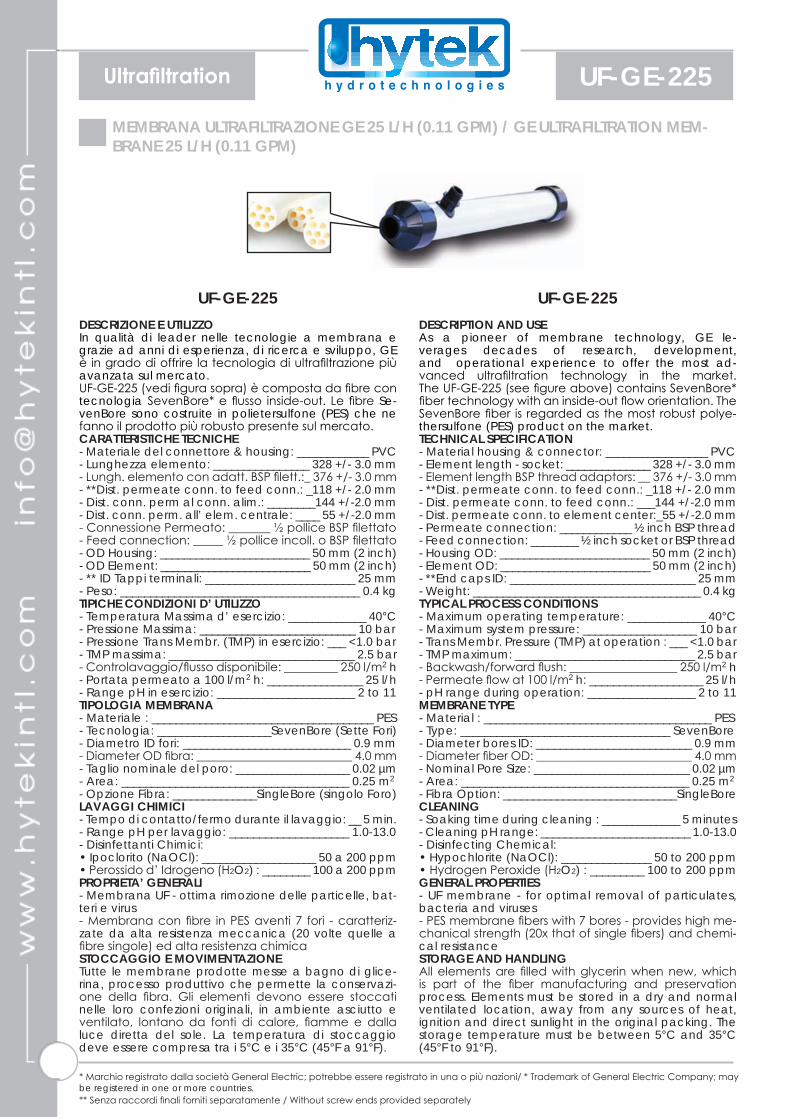
UF-GE-225DESCRIZIONE E UTILIZZOIn qualità di leader nelle tecnologie a membrana e grazie ad anni di esperienza, di ricerca e sviluppo, GE è in grado di offrire la tecnologia di ultrafiltrazione più avanzata sul mercato.UF-GE-225 (vedi figura sopra) è composta da fibre con tecnologia SevenBore* e flusso inside-out. Le fibre Se-venBore sono costruite in polietersulfone (PES) che ne fanno il prodotto più robusto presente sul mercato. CARATTERISTICHE TECNICHE- Materiale del connettore & housing: ____________ PVC- Lunghezza elemento: ________________ 328 +/- 3.0 mm- Lungh. elemento con adatt. BSP filett.:_ 376 +/- 3.0 mm- **Dist. permeate conn. to feed conn.: _118 +/- 2.0 mm- Dist. conn. perm al conn. alim.: ________144 +/-2.0 mm- Dist. conn. perm. all’ elem. centrale: ____ 55 +/-2.0 mm- Connessione Permeato: _______ ½ pollice BSP filettato- Feed connection: _____ ½ pollice incoll. o BSP filettato- OD Housing: _________________________ 50 mm (2 inch)- OD Element: _________________________ 50 mm (2 inch)- ** ID Tappi terminali: _________________________ 25 mm - Peso: ________________________________________ 0.4 kgTIPICHE CONDIZIONI D’ UTILIZZO- Temperatura Massima d’ esercizio: _____________ 40°C - Pressione Massima: __________________________ 10 bar - Pressione Trans Membr. (TMP) in esercizio: ___ <1.0 bar- TMP massima: _______________________________ 2.5 bar - Controlavaggio/flusso disponibile: _________ 250 l/m2 h- Portata permeato a 100 l/m2 h: ________________ 25 l/h- Range pH in esercizio: _______________________ 2 to 11TIPOLOGIA MEMBRANA- Materiale : _____________________________________ PES - Tecnologia: ___________________SevenBore (Sette Fori) - Diametro ID fori: ____________________________ 0.9 mm- Diameter OD fibra: __________________________ 4.0 mm- Taglio nominale del poro: ___________________ 0.02 µm- Area: ______________________________________ 0.25 m2 - Opzione Fibra: ______________SingleBore (singolo Foro) LAVAGGI CHIMICI- Tempo di contatto/fermo durante il lavaggio: __ 5 min.- Range pH per lavaggio: ____________________ 1.0-13.0 - Disinfettanti Chimici: • Ipoclorito (NaOCl): ___________________ 50 a 200 ppm • Perossido d’ Idrogeno (H2O2) : ________ 100 a 200 ppm PROPRIETA’ GENERALI - Membrana UF - ottima rimozione delle particelle, bat-teri e virus - Membrana con fibre in PES aventi 7 fori - caratteriz-zate da alta resistenza meccanica (20 volte quelle a fibre singole) ed alta resistenza chimicaSTOCCAGGIO E MOVIMENTAZIONE Tutte le membrane prodotte messe a bagno di glice-rina, processo produttivo che permette la conservazi-one della fibra. Gli elementi devono essere stoccati nelle loro confezioni originali, in ambiente asciutto e ventilato, lontano da fonti di calore, fiamme e dalla luce diretta del sole. La temperatura di stoccaggio deve essere compresa tra i 5°C e i 35°C (45°F a 91°F).
UF-GE-225DESCRIPTION AND USEAs a pioneer of membrane technology, GE le-verages decades of research, development, and operational experience to offer the most ad-vanced ultrafiltration technology in the market. The UF-GE-225 (see figure above) contains SevenBore* fiber technology with an inside-out flow orientation. The SevenBore fiber is regarded as the most robust polye-thersulfone (PES) product on the market. TECHNICAL SPECIFICATION- Material housing & connector: _________________ PVC- Element length - socket: ______________ 328 +/- 3.0 mm- Element length BSP thread adaptors: __ 376 +/- 3.0 mm- **Dist. permeate conn. to feed conn.: _118 +/- 2.0 mm- Dist. permeate conn. to feed conn.: ___144 +/-2.0 mm- Dist. permeate conn. to element center:_55 +/-2.0 mm- Permeate connection: ____________ ½ inch BSP thread- Feed connection: ________ ½ inch socket or BSP thread- Housing OD: _________________________ 50 mm (2 inch)- Element OD: _________________________ 50 mm (2 inch)- **End caps ID: _______________________________ 25 mm - Weight: ______________________________________ 0.4 kgTYPICAL PROCESS CONDITIONS- Maximum operating temperature: _____________ 40°C - Maximum system pressure: ___________________ 10 bar - Trans Membr. Pressure (TMP) at operation : ___ <1.0 bar- TMP maximum: ______________________________ 2.5 bar - Backwash/forward flush: __________________ 250 l/m2 h- Permeate flow at 100 l/m2 h: ___________________ 25 l/h- pH range during operation: __________________ 2 to 11MEMBRANE TYPE- Material : ______________________________________ PES - Type: ___________________________________ SevenBore - Diameter bores ID: __________________________ 0.9 mm- Diameter fiber OD: __________________________ 4.0 mm- Nominal Pore Size: __________________________ 0.02 µm- Area: ______________________________________ 0.25 m2 - Fibra Option: _____________________________SingleBore CLEANING- Soaking time during cleaning : _____________ 5 minutes- Cleaning pH range: _________________________ 1.0-13.0 - Disinfecting Chemical: • Hypochlorite (NaOCl): _______________ 50 to 200 ppm • Hydrogen Peroxide (H2O2) : _________ 100 to 200 ppm GENERAL PROPERTIES- UF membrane - for optimal removal of particulates, bacteria and viruses - PES membrane fibers with 7 bores - provides high me-chanical strength (20x that of single fibers) and chemi-cal resistanceSTORAGE AND HANDLING All elements are filled with glycerin when new, which is part of the fiber manufacturing and preservation process. Elements must be stored in a dry and normal ventilated location, away from any sources of heat, ignition and direct sunlight in the original packing. The storage temperature must be between 5°C and 35°C (45°F to 91°F).
* Marchio registrato dalla società General Electric; potrebbe essere registrato in una o più nazioni/ * Trademark of General Electric Company; may be registered in one or more countries.** Senza raccordi finali forniti separatamente / Without screw ends provided separately

DISEGNO/ DRAWING
UltrafiltrationUF-GE-225TYPICAL APPLICATION• Pretreatment for reverse osmosis• High quality industrial process• Non water applications like juice, wine and beer cla-rification• High pressure offshore EOR (Enhanced Oil Recovery)• 4 log virus removalCERTIFICATION- KIWA
APPLICAZIONI TIPICHE• Pre-trattamento all’ osmosi inversa• Produzione di acqua di alta qualità nell’ industria• Applicazioni differenti dall’ acqua come la chiarifica-zione dei succhi di frutta, del vino e della birra• Applicazioni EOR offshore (recupero olio/petrolio)• Rimozioni di virus 4 logCERTIFICAZIONE- KIWA

Ultrafiltration UF-GE-250MEMBRANA ULTRAFILTRAZIONE GE 60 L/H (0.26 GPM) / GE ULTRAFILTRATION MEM-BRANE 60 L/H (0.26 GPM)
UF-GE-250DESCRIZIONE E UTILIZZOIn qualità di leader nelle tecnologie a membrana e grazie ad anni di esperienza, di ricerca e sviluppo, GE è in grado di offrire la tecnologia di ultrafiltrazione più avanzata sul mercato.UF-GE-250 (vedi figura sopra) è composta da fibre con tecnologia SevenBore* e flusso inside-out. Le fibre Se-venBore sono costruite in polietersulfone (PES) che ne fanno il prodotto più robusto presente sul mercato. CARATTERISTICHE TECNICHE- Materiale del connettore & housing: ____________ PVC- **Lunghezza elemento - con adatt.: ___ 578 +/- 3.0 mm- Lungh. elemento con adatt. BSP filett.:_ 628 +/- 3.0 mm- Dist. permeate conn. to feed conn.: _118 +/- 2.0 mm- Dist. conn. perm al conn. alim.: ________144 +/-2.0 mm- Dist. conn. perm. all’ elem. centrale: ____ 55 +/-2.0 mm- Connessione Permeato: _______ ½ pollice BSP filettato- Feed connection: _____ ½ pollice incoll. o BSP filettato- OD Housing: _________________________ 50 mm (2 inch)- OD Element: _________________________ 50 mm (2 inch)- ** ID Tappi terminali: _________________________ 25 mm - Peso: ________________________________________ 0.7 kgTIPICHE CONDIZIONI D’ UTILIZZO- Temperatura Massima d’ esercizio: _____________ 40°C - Pressione Massima: __________________________ 10 bar - Pressione Trans Membr. (TMP) in esercizio: ___ <1.0 bar- TMP massima: _______________________________ 2.5 bar - Controlavaggio/flusso disponibile: _________ 250 l/m2 h- Portata permeato a 100 l/m2 h: ________________ 60 l/h- Range pH in esercizio: _______________________ 2 to 11TIPOLOGIA MEMBRANA- Materiale : _____________________________________ PES - Tecnologia: ___________________SevenBore (Sette Fori) - Diametro ID fori: ____________________________ 0.9 mm- Diameter OD fibra: __________________________ 4.0 mm- Taglio nominale del poro: ___________________ 0.02 µm- Area: ________________________________________ 0.6 m2 - Opzione Fibra: ______________SingleBore (singolo Foro) LAVAGGI CHIMICI- Tempo di contatto/fermo durante il lavaggio: __ 5 min.- Range pH per lavaggio: ____________________ 1.0-13.0 - Disinfettanti Chimici: • Ipoclorito (NaOCl): ___________________ 50 a 200 ppm • Perossido d’ Idrogeno (H2O2) : ________ 100 a 200 ppm PROPRIETA’ GENERALI - Membrana UF - ottima rimozione delle particelle, bat-teri e virus - Membrana con fibre in PES aventi 7 fori - caratteriz-zate da alta resistenza meccanica (20 volte quelle a fibre singole) ed alta resistenza chimicaSTOCCAGGIO E MOVIMENTAZIONE Tutte le membrane prodotte messe a bagno di glice-rina, processo produttivo che permette la conservazi-one della fibra. Gli elementi devono essere stoccati nelle loro confezioni originali, in ambiente asciutto e ventilato, lontano da fonti di calore, fiamme e dalla luce diretta del sole. La temperatura di stoccaggio deve essere compresa tra i 5°C e i 35°C (45°F a 91°F).
UF-GE-250DESCRIPTION AND USEAs a pioneer of membrane technology, GE le-verages decades of research, development, and operational experience to offer the most ad-vanced ultrafiltration technology in the market. The UF-GE-250 (see figure above) contains SevenBore* fiber technology with an inside-out flow orientation. The SevenBore fiber is regarded as the most robust polye-thersulfone (PES) product on the market. TECHNICAL SPECIFICATION- Material housing & connector: _________________ PVC- Element length** - socket: ____________ 578 +/- 3.0 mm- Element length BSP thread adaptors: __ 628 +/- 3.0 mm- **Dist. permeate conn. to feed conn.: _118 +/- 2.0 mm- Dist. permeate conn. to feed conn.: ___144 +/-2.0 mm- Dist. permeate conn. to element center:_55 +/-2.0 mm- Permeate connection: ____________ ½ inch BSP thread- Feed connection: ________ ½ inch socket or BSP thread- Housing OD: _________________________ 50 mm (2 inch)- Element OD: _________________________ 50 mm (2 inch)- **End caps ID: _______________________________ 25 mm - Weight: ______________________________________ 0.7 kgTYPICAL PROCESS CONDITIONS- Maximum operating temperature: _____________ 40°C - Maximum system pressure: ___________________ 10 bar - Trans Membr. Pressure (TMP) at operation : ___ <1.0 bar- TMP maximum: ______________________________ 2.5 bar - Backwash/forward flush: __________________ 250 l/m2 h- Permeate flow at 100 l/m2 h: ___________________ 60 l/h- pH range during operation: __________________ 2 to 11MEMBRANE TYPE- Material : ______________________________________ PES - Type: ___________________________________ SevenBore - Diameter bores ID: __________________________ 0.9 mm- Diameter fiber OD: __________________________ 4.0 mm- Nominal Pore Size: __________________________ 0.02 µm- Area: ________________________________________ 0.6 m2 - Fibra Option: _____________________________SingleBore CLEANING- Soaking time during cleaning : _____________ 5 minutes- Cleaning pH range: _________________________ 1.0-13.0 - Disinfecting Chemical: • Hypochlorite (NaOCl): _______________ 50 to 200 ppm • Hydrogen Peroxide (H2O2) : _________ 100 to 200 ppm GENERAL PROPERTIES- UF membrane - for optimal removal of particulates, bacteria and viruses - PES membrane fibers with 7 bores - provides high me-chanical strength (20x that of single fibers) and chemi-cal resistanceSTORAGE AND HANDLING All elements are filled with glycerin when new, which is part of the fiber manufacturing and preservation process. Elements must be stored in a dry and normal ventilated location, away from any sources of heat, ignition and direct sunlight in the original packing. The storage temperature must be between 5°C and 35°C (45°F to 91°F).
* Marchio registrato dalla società General Electric; potrebbe essere registrato in una o più nazioni/ * Trademark of General Electric Company; may be registered in one or more countries.** Senza raccordi finali forniti separatamente / Without screw ends provided separately

DISEGNO/ DRAWING
UltrafiltrationUF-GE-250TYPICAL APPLICATION• Pretreatment for reverse osmosis• High quality industrial process• Non water applications like juice, wine and beer cla-rification• High pressure offshore EOR (Enhanced Oil Recovery)• 4 log virus removalCERTIFICATION- KIWA
APPLICAZIONI TIPICHE• Pre-trattamento all’ osmosi inversa• Produzione di acqua di alta qualità nell’ industria• Applicazioni differenti dall’ acqua come la chiarifica-zione dei succhi di frutta, del vino e della birra• Applicazioni EOR offshore (recupero olio/petrolio)• Rimozioni di virus 4 logCERTIFICAZIONE- KIWA