
MANUALE UTENTE STUFE A PELLET MANUEL UTILISATEUR POÊLES À PELLET … · made in italy marta idro...
140
MARTA IDRO 2.0 - JOLE IDRO 2.0 MADE IN I T A L Y design & production 004276835 - REV.000 IT MANUALE UTENTE STUFE A PELLET UK PELLET STOVES USER MANUAL FR MANUEL UTILISATEUR POÊLES À PELLET DE BENUTZERHANDBUCH PELLETÖFEN ES MANUAL DEL USUARIO ESTUFAS DE PELLET
Transcript of MANUALE UTENTE STUFE A PELLET MANUEL UTILISATEUR POÊLES À PELLET … · made in italy marta idro...

MARTA IDRO 2.0 - JOLE IDRO 2.0MADE IN ITALYdesign & production
004276835 - REV.000
IT MANUALE UTENTE STUFE A PELLETUK PELLET STOVES USER MANUALFR MANUEL UTILISATEUR POÊLES À PELLETDE BENUTZERHANDBUCH PELLETÖFENES MANUAL DEL USUARIO ESTUFAS DE PELLET

ApplicAre etichettA dAti technici
2
ATTENZIONE
LE SUPERFICI POSSONO DIVENTARE MOLTO CALDE! UTILIZZARE SEMPRE I GUANTI DI PROTEZIONE!
ATTENZIONE
Durante la combustione viene sprigionata energia termica che comporta un marcato riscaldamento delle super�ci, di porte, maniglie, comandi, vetri, tubo fumi ed eventualmente della parte anteriore dell’apparecchio. Evitate il contatto con tali elementi senza un corrispondente abbigliamento protettivo (guanti di protezione in dotazione).Fate in modo che i bambini siano consapevoli di questi pericoli e teneteli lontani dal focolare durante il suo funzionamento.
ITALIANO .......................................................................................................................................................................................................... 8
AVVERTENZE .................................................................................................................................................................................................... 8SICUREZZA ....................................................................................................................................................................................................... 8ORDINARIA MANUTENZIONE ......................................................................................................................................................................... 9IMPIANTO IDRAULICO ................................................................................................................................................................................... 10
INSTALLAZIONE E DISPOSITIVI DI SICUREZZA .............................................................................................................................................................................10DISPOSITIVO ANTICONDENSA (OBBLIGATORIO) ...................................................................................................................................... 11KIT PRODUZIONE ACQUA CALDA SANITARIA ISTANTANEA ..................................................................................................................... 12
POSIZIONAMENTO STUFA ....................................................................................................................................................................................................................12RIARMI ............................................................................................................................................................................................................. 12CARATTERISTICHE TERMOPRODOTTI ......................................................................................................................................................... 12INSTALLAZIONE ............................................................................................................................................................................................. 13PELLET E CARICAMENTO .............................................................................................................................................................................. 15VERIFICHE E ACCORTEZZE PER LA PRIMA ACCENSIONE ........................................................................................................................... 15
IL MOTORE DI CARICO PELLET NON FUNZIONA: ........................................................................................................................................................................15TERMOSTATI A BULBO - RIARMI .........................................................................................................................................................................................................15
QUADRO COMANDI ....................................................................................................................................................................................... 16LEGENDA ICONE DISPLAY .....................................................................................................................................................................................................................16MENÙ GENERALE .....................................................................................................................................................................................................................................17ISTRUZIONI DI BASE ...............................................................................................................................................................................................................................17
IL TELECOMANDO .......................................................................................................................................................................................... 18ABILITA SPEGNIMENTO RITARDATO .................................................................................................................................................................................................18TIPOLOGIA E SOSTITUZIONE DELLE BATTERIE ............................................................................................................................................................................18
IMPOSTAZIONI PER LA PRIMA ACCENSIONE .............................................................................................................................................. 19FREQUENZA DI RETE 50/ 60HZ ...........................................................................................................................................................................................................19REGOLAZIONE ORA, GIORNO, MESE E ANNO ..............................................................................................................................................................................19REGOLAZIONE DELLA LINGUA ...........................................................................................................................................................................................................19
ALTRE FUNZIONI ............................................................................................................................................................................................ 19SCARICO ARIA ............................................................................................................................................................................................................................................19PRIMO CARICO ..........................................................................................................................................................................................................................................19
FUNZIONAMENTO E LOGICA ........................................................................................................................................................................ 20TERMOSTATO SUPPLEMENTARE .................................................................................................................................................................. 21
FUNZIONAMENTO TERMOSTATO SUPPLEMENTARE CON STBY ATTIVO ...........................................................................................................................21FUNZIONAMENTO TERMOSTATO SUPPLEMENTARE CON STBY DISATTIVO ....................................................................................................................21INSTALLAZIONE TERMOSTATO SUPPLEMENTARE ......................................................................................................................................................................21
SET POTENZA ................................................................................................................................................................................................. 22SET TEMPERATURE ........................................................................................................................................................................................ 22MENU UTENTE ................................................................................................................................................................................................ 22
ABILITA ARIA...............................................................................................................................................................................................................................................22V1 - ARIA ......................................................................................................................................................................................................................................................22RESET .............................................................................................................................................................................................................................................................23EASY SET UP ...............................................................................................................................................................................................................................................23
SET CRONO ..................................................................................................................................................................................................... 23STATO .............................................................................................................................................................................................................. 24IMPOSTAZIONI ............................................................................................................................................................................................... 24
SET OROLOGIO .........................................................................................................................................................................................................................................24REGOLAZIONE DELLA LINGUA ...........................................................................................................................................................................................................24DISPLAY ........................................................................................................................................................................................................................................................24STAND - BY ..................................................................................................................................................................................................................................................25
AUX .................................................................................................................................................................................................................. 25PULIZIA E MANUTENZIONE .......................................................................................................................................................................... 26MANUTENZIONE ORDINARIA ESEGUITA DAI TECNICI ABILITATI ............................................................................................................ 28
MESSA FUORI SERVIZIO (FINE STAGIONE) .....................................................................................................................................................................................28VISUALIZZAZIONI .......................................................................................................................................................................................... 30ALLARMI ......................................................................................................................................................................................................... 30CONDIZIONI DI GARANZIA ............................................................................................................................................................................................32
3
ATTENTION
SURFACES CAN BECOME VERY HOT!ALWAYS USE PROTECTIVE GLOVES!
During combustion, thermal energy is released that signi�cantly increases the heat of surfaces, doors, handles, controls, glass, exhaust pipes, and even the front of the appliance. Avoid contact with those elements if not wearing protective clothing (protective gloves included). Make sure children are aware of the danger and keep them away from the stove during operation.
ENGLISH .......................................................................................................................................................................................................... 34
WARNINGS ...................................................................................................................................................................................................... 34SAFETY ............................................................................................................................................................................................................ 34ROUTINE MAINTENANCE .............................................................................................................................................................................. 35HYDRAULIC SYSTEM ...................................................................................................................................................................................... 36
INSTALLATION AND SAFETY DEVICES .............................................................................................................................................................................................36ANTI-CONDENSATION DEVICE (MANDATORY) .......................................................................................................................................... 37INSTANT DOMESTIC HOT WATER PRODUCTION KIT ................................................................................................................................. 38
STOVE POSITIONING ...............................................................................................................................................................................................................................38REARMING ...................................................................................................................................................................................................... 38THERMO-PRODUCTS FEATURES .................................................................................................................................................................. 38INSTALLATION ................................................................................................................................................................................................ 39PELLETS AND FEEDING ................................................................................................................................................................................. 41CHECKS AND PRECAUTIONS FOR FIRST IGNITION .................................................................................................................................... 41
THE PELLET LOADING MOTOR DOES NOT WORK: ...............................................................................................................................................................41BULB THERMOSTATS - RESET: ..............................................................................................................................................................................................................41
CONTROL PANEL ............................................................................................................................................................................................ 42DISPLAY ICONS KEY .................................................................................................................................................................................................................................42GENERAL MENU ........................................................................................................................................................................................................................................43BASIC INSTRUCTIONS ............................................................................................................................................................................................................................43
THE REMOTE CONTROL ................................................................................................................................................................................. 44ENABLE DELAYED SWITCH-OFF .........................................................................................................................................................................................................44TYPE AND REPLACEMENT OF BATTERIES .......................................................................................................................................................................................44
COMMISSIONING SETTINGS ......................................................................................................................................................................... 45MAINS FREQUENCY 50/ 60HZ .............................................................................................................................................................................................................45ADJUSTING TIME, DAY, MONTH AND YEAR ...................................................................................................................................................................................45ADJUSTING LANGUAGE.........................................................................................................................................................................................................................45
OTHER FUNCTIONS ........................................................................................................................................................................................ 45AIR DISCHARGE .........................................................................................................................................................................................................................................45FIRST LOAD .................................................................................................................................................................................................................................................45
OPERATION AND LOGIC ................................................................................................................................................................................ 46ADDITIONAL THERMOSTAT .......................................................................................................................................................................... 47
ADDITIONAL THERMOSTAT FUNCTIONING WITH STBY ACTIVE ...........................................................................................................................................47ADDITIONAL THERMOSTAT FUNCTIONING WITH STBY DEACTIVATED .............................................................................................................................47ADDITIONAL THERMOSTAT INSTALLATION ...................................................................................................................................................................................47
SET POWER ..................................................................................................................................................................................................... 48TEMPERATURE SET ........................................................................................................................................................................................ 48USER MENU..................................................................................................................................................................................................... 48
ENABLE FAN ................................................................................................................................................................................................................................................48V1- AIR...........................................................................................................................................................................................................................................................48RESET .............................................................................................................................................................................................................................................................49EASY SET UP ...............................................................................................................................................................................................................................................49
SET CHRONO .................................................................................................................................................................................................. 49STATUS ............................................................................................................................................................................................................ 50SETTINGS ........................................................................................................................................................................................................ 50
SET CLOCK ..................................................................................................................................................................................................................................................50ADJUSTING LANGUAGE.........................................................................................................................................................................................................................50DISPLAY ........................................................................................................................................................................................................................................................50STAND - BY ..................................................................................................................................................................................................................................................51
AUX .................................................................................................................................................................................................................. 51CLEANING AND MAINTENANCE ................................................................................................................................................................... 52ROUTINE MAINTENANCE CARRIED OUT BY AUTHORISED TECHNICIANS ............................................................................................. 54
PUTTING THE EQUIPMENT OUT OF SERVICE (END OF THE SEASON) .................................................................................................................................54DISPLAYS ........................................................................................................................................................................................................ 56ALARMS .......................................................................................................................................................................................................... 56GUARANTEE TERMS ...................................................................................................................................................................................... 58
4
ATTENTION
LES SURFACES PEUVENT DEVENIR TRÈS CHAUDES !UTILISER TOUJOURS DES GANTS DE PROTECTION !
A
Une énergie thermique est emprisonnée pendant la combustion et rend les surfaces, les portes, les poignées, les commandes, les vitres, le tuyau d’évacuation des fumées et éventuellement la partie antérieure de l’appareil considérablement chaudes.Il ne faut pas toucher les éléments en question sans être muni de vêtements de protection (gants de protection fournis).Il faut faire en sorte de bien expliquer ce danger aux enfants et de ne pas les faire approcher du foyer pendant le fonctionnement.
FRANÇAIS ....................................................................................................................................................................................................... 60
MISES EN GARDE ............................................................................................................................................................................................ 60SÉCURITÉ ........................................................................................................................................................................................................ 60ENTRETIEN ORDINAIRE ................................................................................................................................................................................. 61HYDRAULIKANLAGE ...................................................................................................................................................................................... 62
INSTALLATION UND SICHERHEITSVORRICHTUNGEN ................................................................................................................................................................62VORRICHTUNG GEGEN KONDENSATBILDUNG (VERPFLICHTEND) ......................................................................................................... 63KIT DE PRODUCTION D'EAU CHAUDE SANITAIRE INSTANTANÉE ............................................................................................................ 64
POSITIONNEMENT DU POÊLE .............................................................................................................................................................................................................64RÉARMEMENTS .............................................................................................................................................................................................. 64CARACTERISTIQUES DES THERMOPRODUITS ............................................................................................................................................ 64INSTALLATION ................................................................................................................................................................................................ 65PELLET ET CHARGEMENT .............................................................................................................................................................................. 67VÉRIFICATIONS ET PRÉCAUTIONS POUR LE PREMIER ALLUMAGE .......................................................................................................... 67
LE MOTEUR DE CHARGEMENT DES PELLETS NE FONCTIONNE PAS : .................................................................................................................................67THERMOSTATS À BULBE - RÉARMEMENTS : ...................................................................................................................................................................................67
CONSOLE DES COMMANDES ........................................................................................................................................................................ 68LÉGENDE DES ICÔNES DE L'AFFICHEUR ..........................................................................................................................................................................................68MENU GÉNÉRAL ........................................................................................................................................................................................................................................69INSTRUCTIONS DE BASE ......................................................................................................................................................................................................................69
LA TÉLÉCOMMANDE ...................................................................................................................................................................................... 70HABILITATION ARRÊT RETARDÉ ..........................................................................................................................................................................................................70TYPE ET REMPLACEMENT DES PILES................................................................................................................................................................................................70
CONFIGURATIONS POUR LE PREMIER ALLUMAGE .................................................................................................................................... 71FRÉQUENCE DE RÉSEAU 50/60 HZ ....................................................................................................................................................................................................71RÉGLAGE DE L'HEURE, JOUR, MOIS ET ANNÉE .............................................................................................................................................................................71RÉGLAGE DE LA LANGUE ......................................................................................................................................................................................................................71
AUTRES FONCTIONS ...................................................................................................................................................................................... 71ÉVAC. AIR .....................................................................................................................................................................................................................................................71CHARGE INITIALE .....................................................................................................................................................................................................................................71
FONCTIONNEMENT ET LOGIQUE ................................................................................................................................................................. 72THERMOSTAT SUPPLÉMENTAIRE ................................................................................................................................................................. 73
FONCTIONNEMENT DU THERMOSTAT SUPPLÉMENTAIRE AVEC STBY ACTIVÉ ...............................................................................................................73FONCTIONNEMENT DU THERMOSTAT SUPPLÉMENTAIRE AVEC STBY DÉSACTIVÉ ......................................................................................................73INSTALLATION DU THERMOSTAT SUPPLÉMENTAIRE .................................................................................................................................................................73
SET PUISSANCE .............................................................................................................................................................................................. 74SET TEMPÉRATURES ...................................................................................................................................................................................... 74MENU UTILISATEUR ....................................................................................................................................................................................... 74
HABILIT.VENT. .............................................................................................................................................................................................................................................74VENTIL-1 AIR ...............................................................................................................................................................................................................................................74EFFACER .......................................................................................................................................................................................................................................................75EASY SET UP ...............................................................................................................................................................................................................................................75
SET CHRONO .................................................................................................................................................................................................. 75ÉTAT ................................................................................................................................................................................................................. 76CONFIGURATIONS ......................................................................................................................................................................................... 76
SET HORLOGE ...........................................................................................................................................................................................................................................76RÉGLAGE DE LA LANGUE ......................................................................................................................................................................................................................76AFFICHEUR ..................................................................................................................................................................................................................................................76STAND-BY ....................................................................................................................................................................................................................................................77
AUX .................................................................................................................................................................................................................. 77NETTOYAGE ET ENTRETIEN ........................................................................................................................................................................... 78ENTRETIEN ORDINAIRE EFFECTUÉ PAR DES TECHNICIENS AUTORISÉS ................................................................................................ 80
MISE HORS SERVICE (FIN DE SAISON) .............................................................................................................................................................................................80VISUALISATIONS ............................................................................................................................................................................................ 82ALARMES ........................................................................................................................................................................................................ 82CONDITIONS DE GARANTIE ......................................................................................................................................................................... 84
5

ACHTUNG
DIE OBERFLÄCHEN KÖNNEN SEHR HEISS WERDEN!VERWENDEN SIE IMMER SCHUTZHANDSCHUHE!
A
Während der Verbrennung wird Wärmeenergie freigegeben, was zu einer bedeutenden Erhitzung der Ober�ächen, von Türen, Gri�en, Steuerungen, Glas, Abgasrohr und eventuell der Vorderseite des Geräts führt.Vermeiden Sie den Kontakt mit diesen Elementen ohne entsprechende Schutzkleidung (Schutzhandschuhe in der Ausstattung).Stellen Sie sicher, dass Kinder sich dieser Gefahren bewusst sind und halten Sie sie vom Feuerraum während seines Betriebs fern.
DEUTSCH ......................................................................................................................................................................................................... 86
WARNHINWEISE ............................................................................................................................................................................................. 86SICHERHEIT .................................................................................................................................................................................................... 86FACHGERECHTE WARTUNG .......................................................................................................................................................................... 87HYDRAULIKANLAGE ...................................................................................................................................................................................... 88
INSTALLATION UND SICHERHEITSVORRICHTUNGEN ................................................................................................................................................................88VORRICHTUNG GEGEN KONDENSATBILDUNG (VERPFLICHTEND) ......................................................................................................... 89BAUSATZ SOFORT-TRINKWASSERERWÄRMUNG ....................................................................................................................................... 90
AUFSTELLUNG DES OFENS ...................................................................................................................................................................................................................90STB - RÜCKSETZUNG ..................................................................................................................................................................................... 90EIGENSCHAFTEN DER HEIZGERÄTE ............................................................................................................................................................. 90INSTALLATION ................................................................................................................................................................................................ 91PELLETS UND PELLETZUFUHR ..................................................................................................................................................................... 93ÜBERPRÜFUNGEN UND VORKEHRUNGEN VOR DER ERSTMALIGEN ZÜNDUNG .................................................................................... 93
DER MOTOR FÜR DIE PELLETZUFUHR FUNKTIONIERT NICHT: ..............................................................................................................................................93STB - KAPILLARROHRTHERMOSTATE - RÜCKSTELLVORRICHTUNGEN: ..............................................................................................................................93
BEDIENTAFEL ................................................................................................................................................................................................. 94LEGENDE DISPLAY-SYMBOLE ..............................................................................................................................................................................................................94ALLGEMEINES MENÜ ..............................................................................................................................................................................................................................95GRUNDANWEISUNGEN .........................................................................................................................................................................................................................95
DIE FERNBEDIENUNG .................................................................................................................................................................................... 96ABSCHALTVERZÖGERUNG AKTIVIEREN ..........................................................................................................................................................................................96TYP UND AUSTAUSCH DER BATTERIEN ...........................................................................................................................................................................................96
EINSTELLUNGEN FÜR DIE ERSTE INBETRIEBNAHME ................................................................................................................................. 97NETZFREQUENZ 50/ 60 HZ ...................................................................................................................................................................................................................97EINSTELLUNG VON UHRZEIT, TAG, MONAT UND JAHR .............................................................................................................................................................97EINSTELLUNG DER SPRACHE ...............................................................................................................................................................................................................97
SONSTIGE FUNKTIONEN ............................................................................................................................................................................... 97LUFTABLASS ...............................................................................................................................................................................................................................................97ERSTE LADUNG .........................................................................................................................................................................................................................................97
FUNKTIONSWEISE UND -LOGIK ................................................................................................................................................................... 98ZUSATZTHERMOSTAT.................................................................................................................................................................................... 99
BETRIEB ZUSATZTHERMOSTAT BEI AKTIVIERTEM STBY ...........................................................................................................................................................99BETRIEB ZUSATZTHERMOSTAT BEI DEAKTIVIERTEM STBY......................................................................................................................................................99INSTALLATION ZUSATZTHERMOSTAT ..............................................................................................................................................................................................99
SET LEISTUNG .............................................................................................................................................................................................. 100SET TEMPERATUR ........................................................................................................................................................................................ 100MENUE USER ................................................................................................................................................................................................ 100
LUEFTER FREIGEBEN ............................................................................................................................................................................................................................ 100V1-LÜFTER ................................................................................................................................................................................................................................................ 100RESET .......................................................................................................................................................................................................................................................... 101EASY SET UP ............................................................................................................................................................................................................................................ 101
SET CHRONO ................................................................................................................................................................................................ 101STATUS .......................................................................................................................................................................................................... 102EINSTELLUNGEN .......................................................................................................................................................................................... 102
SET UHR .................................................................................................................................................................................................................................................... 102EINSTELLUNG DER SPRACHE ............................................................................................................................................................................................................ 102DISPLAY ..................................................................................................................................................................................................................................................... 102STAND-BY ................................................................................................................................................................................................................................................. 103
AUX ................................................................................................................................................................................................................ 103REINIGUNG UND WARTUNG ....................................................................................................................................................................... 104VON ZUGELASSENEN FACHTECHNIKERN AUSGEFÜHRTE FACHMÄNNISCHE WARTUNG................................................................... 106
AUSSERBETRIEBNAHME (SAISONENDE) ...................................................................................................................................................................................... 106ANZEIGEN ..................................................................................................................................................................................................... 108ALARME ........................................................................................................................................................................................................ 108GARANTIEBEDINGUNGEN ......................................................................................................................................................................... 110
6

ATENCIÓN
¡LAS SUPERFICIES SE PUEDEN CALENTAR MUCHO!¡SIEMPRE SE DEBEN USAR GUANTES DE PROTECCIÓN!
A
Durante la combustión se emana energía térmica que comporta un notable calentamiento de las super�cies, de las puertas, manijas, mandos, vidrios, tubo de humos y eventualmente de la parte delantera del aparato.Eviten el contacto con estos elementos sin la adecuada indumentaria protectora (guantes de protección en dotación).Asegúrense que los niños sean conscientes de estos peligros y mantenerlos alejados del fogón durante su funcionamiento.
ESPAÑOL ....................................................................................................................................................................................................... 112
ADVERTENCIAS ............................................................................................................................................................................................ 112SEGURIDAD .................................................................................................................................................................................................. 112MANTENIMIENTO ORDINARIO ................................................................................................................................................................... 113INSTALACIÓN HIDRÁULICA ........................................................................................................................................................................ 114
INSTALACIÓN Y DISPOSITIVOS DE SEGURIDAD ....................................................................................................................................................................... 114DISPOSITIVO ANTICONDENSACIÓN (OBLIGATORIO) .............................................................................................................................. 115KIT PRODUCCIÓN DE AGUA CALIENTE SANITARIA INSTANTÁNEA ........................................................................................................ 116
COLOCACIÓN DE LA ESTUFA ............................................................................................................................................................................................................ 116RESTABLECIMIENTO .................................................................................................................................................................................... 116CARACTERÍSTICAS DE LOS EQUIPOS TÉRMICOS ..................................................................................................................................... 116INSTALACIÓN ............................................................................................................................................................................................... 117PELLET Y CARGA .......................................................................................................................................................................................... 119CONTROLES Y PRECAUCIONES PARA EL PRIMER ENCENDIDO .............................................................................................................. 119
EL MOTOR DE CARGA DE PELLET NO FUNCIONA: ................................................................................................................................................................... 119TERMOSTATOS DE BULBO - REARMES: ......................................................................................................................................................................................... 119
CUADRO DE MANDOS ................................................................................................................................................................................. 120LEYENDA DE LOS ICONOS DE LA PANTALLA ............................................................................................................................................................................. 120MENÚ GENERAL ..................................................................................................................................................................................................................................... 121INSTRUCCIONES DE BASE ................................................................................................................................................................................................................. 121
EL MANDO A DISTANCIA ............................................................................................................................................................................. 122HABILITA EL APAGADO RETRASADO ............................................................................................................................................................................................ 122TIPO Y SUSTITUCIÓN DE LAS BATERÍAS ....................................................................................................................................................................................... 122
CONFIGURACIONES PARA EL PRIMER ENCENDIDO ................................................................................................................................. 123FRECUENCIA DE RED 50/ 60HZ ........................................................................................................................................................................................................ 123REGULACIÓN HORA, DÍA, MES Y AÑO .......................................................................................................................................................................................... 123REGULACIÓN DEL IDIOMA ................................................................................................................................................................................................................ 123
OTRAS FUNCIONES ...................................................................................................................................................................................... 123DESCARGA AIRE ..................................................................................................................................................................................................................................... 123CARGA INICIAL ....................................................................................................................................................................................................................................... 123
FUNCIONAMIENTO Y LÓGICA ..................................................................................................................................................................... 124TERMOSTATO SUPLEMENTARIO ................................................................................................................................................................ 125
FUNCIONAMIENTO DEL TERMOSTATO SUPLEMENTARIO CON STBY ACTIVADO ....................................................................................................... 125FUNCIONAMIENTO DEL TERMOSTATO SUPLEMENTARIO CON STBY DESACTIVADO ............................................................................................... 125INSTALACIÓN DEL TERMOSTATO SUPLEMENTARIO ............................................................................................................................................................... 125
SET POTENCIA .............................................................................................................................................................................................. 126SET TEMPERATURAS .................................................................................................................................................................................... 126MENÚ USUARIO ........................................................................................................................................................................................... 126
HABILIT.VENT. .......................................................................................................................................................................................................................................... 126VENTIL-1 .................................................................................................................................................................................................................................................... 126BORRAR ..................................................................................................................................................................................................................................................... 127EASY SET UP ............................................................................................................................................................................................................................................ 127
SET CHRONO ................................................................................................................................................................................................ 127ESTADO ......................................................................................................................................................................................................... 128CONFIGURACIONES ..................................................................................................................................................................................... 128
SET RELOJ ................................................................................................................................................................................................................................................ 128REGULACIÓN DEL IDIOMA ................................................................................................................................................................................................................ 128PANTALLA ................................................................................................................................................................................................................................................. 128STAND - BY ............................................................................................................................................................................................................................................... 129
AUX ................................................................................................................................................................................................................ 129LIMPIEZA Y MANTENIMIENTO.................................................................................................................................................................... 130MANTENIMIENTO ORDINARIO REALIZADO POR TÉCNICOS HABILITADOS ......................................................................................... 132
PUESTA FUERA DE SERVICIO (FIN DE TEMPORADA) ............................................................................................................................................................... 132VISUALIZACIONES ....................................................................................................................................................................................... 134ALARMAS ...................................................................................................................................................................................................... 134CONDICIONES DE GARANTÍA .................................................................................................................................................................... 136
7
ITALIANO
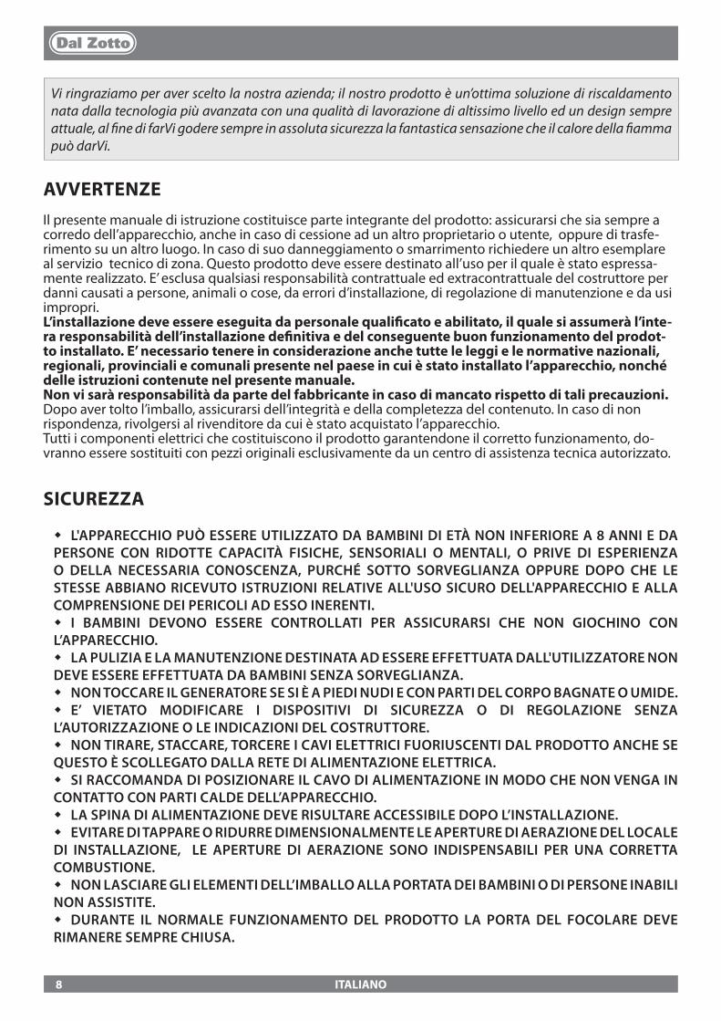
AVVERTENZEIl presente manuale di istruzione costituisce parte integrante del prodotto: assicurarsi che sia sempre a corredo dell’apparecchio, anche in caso di cessione ad un altro proprietario o utente, oppure di trasfe-rimento su un altro luogo. In caso di suo danneggiamento o smarrimento richiedere un altro esemplare al servizio tecnico di zona. Questo prodotto deve essere destinato all’uso per il quale è stato espressa-mente realizzato. E’ esclusa qualsiasi responsabilità contrattuale ed extracontrattuale del costruttore per danni causati a persone, animali o cose, da errori d’installazione, di regolazione di manutenzione e da usi impropri.L’installazione deve essere eseguita da personale quali�cato e abilitato, il quale si assumerà l’inte-ra responsabilità dell’installazione de�nitiva e del conseguente buon funzionamento del prodot-to installato. E’ necessario tenere in considerazione anche tutte le leggi e le normative nazionali, regionali, provinciali e comunali presente nel paese in cui è stato installato l’apparecchio, nonché delle istruzioni contenute nel presente manuale.Non vi sarà responsabilità da parte del fabbricante in caso di mancato rispetto di tali precauzioni.Dopo aver tolto l’imballo, assicurarsi dell’integrità e della completezza del contenuto. In caso di non rispondenza, rivolgersi al rivenditore da cui è stato acquistato l’apparecchio.Tutti i componenti elettrici che costituiscono il prodotto garantendone il corretto funzionamento, do-vranno essere sostituiti con pezzi originali esclusivamente da un centro di assistenza tecnica autorizzato.
SICUREZZA
� L'APPARECCHIO PUÒ ESSERE UTILIZZATO DA BAMBINI DI ETÀ NON INFERIORE A 8 ANNI E DA PERSONE CON RIDOTTE CAPACITÀ FISICHE, SENSORIALI O MENTALI, O PRIVE DI ESPERIENZA O DELLA NECESSARIA CONOSCENZA, PURCHÉ SOTTO SORVEGLIANZA OPPURE DOPO CHE LE STESSE ABBIANO RICEVUTO ISTRUZIONI RELATIVE ALL'USO SICURO DELL'APPARECCHIO E ALLA COMPRENSIONE DEI PERICOLI AD ESSO INERENTI.
� I BAMBINI DEVONO ESSERE CONTROLLATI PER ASSICURARSI CHE NON GIOCHINO CON L’APPARECCHIO.
� LA PULIZIA E LA MANUTENZIONE DESTINATA AD ESSERE EFFETTUATA DALL'UTILIZZATORE NON DEVE ESSERE EFFETTUATA DA BAMBINI SENZA SORVEGLIANZA.
� NON TOCCARE IL GENERATORE SE SI È A PIEDI NUDI E CON PARTI DEL CORPO BAGNATE O UMIDE. � E’ VIETATO MODIFICARE I DISPOSITIVI DI SICUREZZA O DI REGOLAZIONE SENZA
L’AUTORIZZAZIONE O LE INDICAZIONI DEL COSTRUTTORE. � NON TIRARE, STACCARE, TORCERE I CAVI ELETTRICI FUORIUSCENTI DAL PRODOTTO ANCHE SE
QUESTO È SCOLLEGATO DALLA RETE DI ALIMENTAZIONE ELETTRICA. � SI RACCOMANDA DI POSIZIONARE IL CAVO DI ALIMENTAZIONE IN MODO CHE NON VENGA IN
CONTATTO CON PARTI CALDE DELL’APPARECCHIO. � LA SPINA DI ALIMENTAZIONE DEVE RISULTARE ACCESSIBILE DOPO L’INSTALLAZIONE. � EVITARE DI TAPPARE O RIDURRE DIMENSIONALMENTE LE APERTURE DI AERAZIONE DEL LOCALE
DI INSTALLAZIONE, LE APERTURE DI AERAZIONE SONO INDISPENSABILI PER UNA CORRETTA COMBUSTIONE.
� NON LASCIARE GLI ELEMENTI DELL’IMBALLO ALLA PORTATA DEI BAMBINI O DI PERSONE INABILI NON ASSISTITE.
� DURANTE IL NORMALE FUNZIONAMENTO DEL PRODOTTO LA PORTA DEL FOCOLARE DEVE RIMANERE SEMPRE CHIUSA.
Vi ringraziamo per aver scelto la nostra azienda; il nostro prodotto è un’ottima soluzione di riscaldamento nata dalla tecnologia più avanzata con una qualità di lavorazione di altissimo livello ed un design sempre attuale, al �ne di farVi godere sempre in assoluta sicurezza la fantastica sensazione che il calore della �amma può darVi.
8
ITALIANO
� QUANDO L'APPARECCHIO È IN FUNZIONE È CALDO AL TATTO, IN PARTICOLARE TUTTE LE SUPERFICI ESTERNE, PER QUESTO SI RACCOMANDA DI PRESTARE ATTENZIONE
� CONTROLLARE LA PRESENZA DI EVENTUALI OSTRUZIONI PRIMA DI ACCENDERE L’APPARECCHIO IN SEGUITO AD UN LUNGO PERIODO DI MANCATO UTILIZZO.
� IL GENERATORE È STATO PROGETTATO PER FUNZIONARE CON QUALSIASI CONDIZIONE CLIMATICA, IN CASO DI CONDIZIONI PARTICOLARMENTE AVVERSE (VENTO FORTE, GELO) POTREBBERO INTERVENIRE SISTEMI DI SICUREZZA CHE PORTANO IL GENERATORE IN SPEGNIMENTO. SE SI VERIFICA CIÒ CONTATTARE IL SERVIZIO DI ASSISTENZA TECNICA E, IN OGNI CASO, NON DISABILITARE I SISTEMI DI SICUREZZA.
� IN CASO DI INCENDIO DELLA CANNA FUMARIA MUNIRSI DI ADEGUATI SISTEMI PER SOFFOCARE LE FIAMME O RICHIEDERE L’INTERVENTO DEI VIGILI DEL FUOCO.
� QUESTO APPARECCHIO NON DEVE ESSERE UTILIZZATO COME INCENERITORE DI RIFIUTI � NON UTILIZZARE ALCUN LIQUIDO INFIAMMABILE PER L’ACCENSIONE � IN FASE DI RIEMPIMENTO NON PORTARE IL SACCO DI PELLET A CONTATTO CON IL PRODOTTO � LE MAIOLICHE SONO PRODOTTI DI ALTA FATTURA ARTIGIANALE E COME TALI POSSONO
PRESENTARE MICRO-PUNTINATURE, CAVILLATURE ED IMPERFEZIONI CROMATICHE. QUESTE CARATTERISTICHE NE TESTIMONIANO LA PREGIATA NATURA. SMALTO E MAIOLICA, PER IL LORO DIVERSO COEFFICIENTE DI DILATAZIONE, PRODUCONO MICRO SCREPOLATURE (CAVILLATURA) CHE NE DIMOSTRANO L’EFFETTIVA AUTENTICITÀ. PER LA PULIZIA DELLE MAIOLICHE SI CONSIGLIA DI USARE UN PANNO MORBIDO ED ASCIUTTO; SE SI USA UN QUALSIASI DETERGENTE O LIQUIDO, QUEST’ULTIMO POTREBBE PENETRARE ALL’INTERNO DEI CAVILLI EVIDENZIANDO GLI STESSI.
ORDINARIA MANUTENZIONE
In base al decreto 22 gennaio 2008 n°37 art.2 per ordinaria manutenzione sono intesi gli interventi �na-lizzati a contenere il degrado normale d'uso, nonché a far fronte ad eventi accidentali che comportano la necessità di primi interventi, che comunque non modi�cano la struttura dell'impianto su cui si interviene o la sua destinazione d'uso secondo le prescrizioni previste dalla normativa tecnica vigente e dal libretto di uso e manutenzione del costruttore.
9
ITALIANO
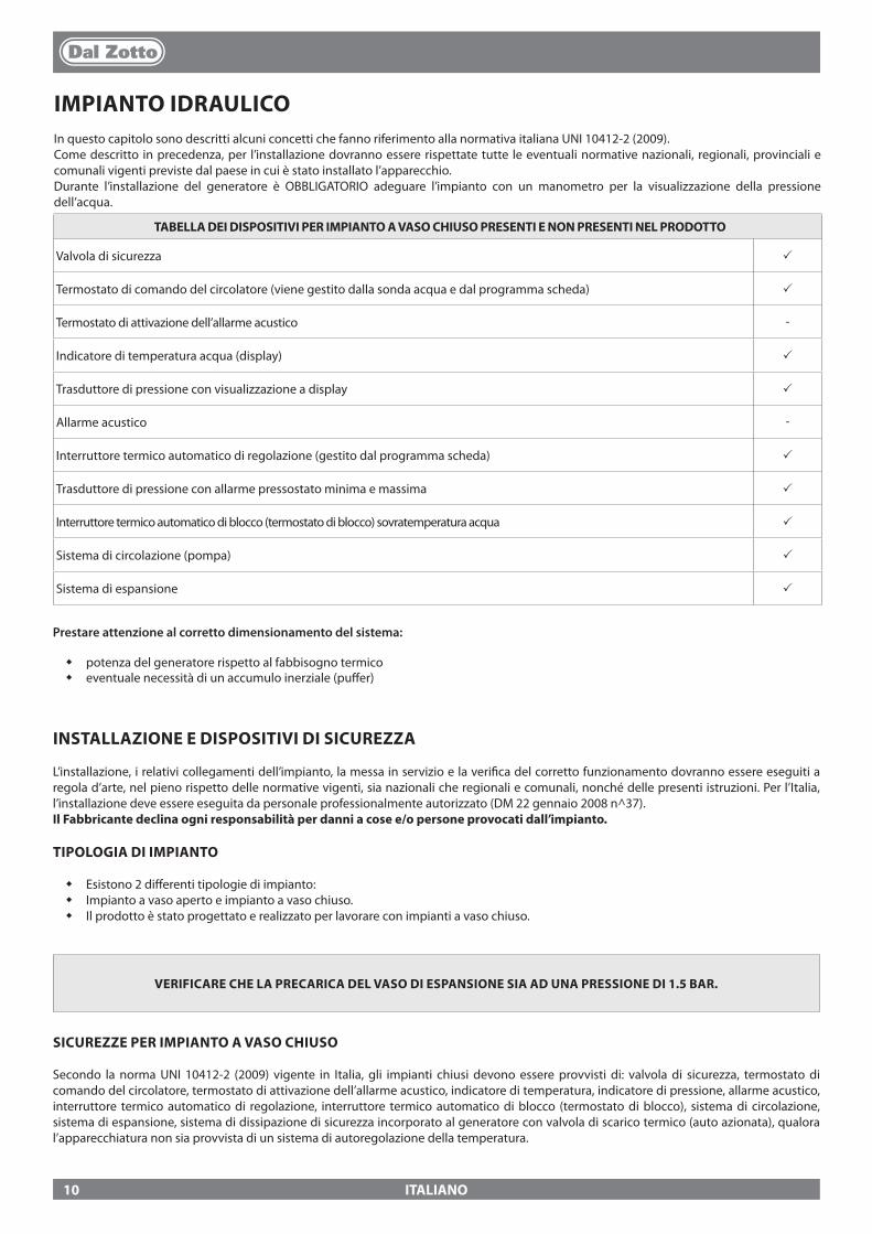
IMPIANTO IDRAULICOIn questo capitolo sono descritti alcuni concetti che fanno riferimento alla normativa italiana UNI 10412-2 (2009). Come descritto in precedenza, per l’installazione dovranno essere rispettate tutte le eventuali normative nazionali, regionali, provinciali e comunali vigenti previste dal paese in cui è stato installato l’apparecchio.Durante l’installazione del generatore è OBBLIGATORIO adeguare l’impianto con un manometro per la visualizzazione della pressione dell’acqua.
TABELLA DEI DISPOSITIVI PER IMPIANTO A VASO CHIUSO PRESENTI E NON PRESENTI NEL PRODOTTO
Valvola di sicurezza p
Termostato di comando del circolatore (viene gestito dalla sonda acqua e dal programma scheda) p
Termostato di attivazione dell’allarme acustico -
Indicatore di temperatura acqua (display) p
Trasduttore di pressione con visualizzazione a display p
Allarme acustico -
Interruttore termico automatico di regolazione (gestito dal programma scheda) p
Trasduttore di pressione con allarme pressostato minima e massima p
Interruttore termico automatico di blocco (termostato di blocco) sovratemperatura acqua p
Sistema di circolazione (pompa) p
Sistema di espansione p
INSTALLAZIONE E DISPOSITIVI DI SICUREZZA
L’installazione, i relativi collegamenti dell’impianto, la messa in servizio e la veri�ca del corretto funzionamento dovranno essere eseguiti a regola d’arte, nel pieno rispetto delle normative vigenti, sia nazionali che regionali e comunali, nonché delle presenti istruzioni. Per l’Italia, l’installazione deve essere eseguita da personale professionalmente autorizzato (DM 22 gennaio 2008 n^37).Il Fabbricante declina ogni responsabilità per danni a cose e/o persone provocati dall’impianto.
TIPOLOGIA DI IMPIANTO
� Esistono 2 di�erenti tipologie di impianto: � Impianto a vaso aperto e impianto a vaso chiuso. � Il prodotto è stato progettato e realizzato per lavorare con impianti a vaso chiuso.
VERIFICARE CHE LA PRECARICA DEL VASO DI ESPANSIONE SIA AD UNA PRESSIONE DI 1.5 BAR.
SICUREZZE PER IMPIANTO A VASO CHIUSO
Secondo la norma UNI 10412-2 (2009) vigente in Italia, gli impianti chiusi devono essere provvisti di: valvola di sicurezza, termostato di comando del circolatore, termostato di attivazione dell’allarme acustico, indicatore di temperatura, indicatore di pressione, allarme acustico, interruttore termico automatico di regolazione, interruttore termico automatico di blocco (termostato di blocco), sistema di circolazione, sistema di espansione, sistema di dissipazione di sicurezza incorporato al generatore con valvola di scarico termico (auto azionata), qualora l’apparecchiatura non sia provvista di un sistema di autoregolazione della temperatura.
Prestare attenzione al corretto dimensionamento del sistema:
� potenza del generatore rispetto al fabbisogno termico � eventuale necessità di un accumulo inerziale (pu�er)
10
ITALIANO
DISTANZE DEI DISPOSITIVI DI SICUREZZA SECONDO LA NORMATIVA
I sensori di sicurezza della temperatura devono essere a bordo macchina o a una distanza non superiore a 30 cm dal collegamento di mandata. Qualora i generatori non siano provvisti di tutti i dispositivi, quelli mancanti, possono essere installati sulla tubazione di mandata del generatore, entro una distanza, dalla macchina, non superiore a 1 m.
CONTROLLI ALLA PRIMA ACCENSIONE
Prima di allacciare la caldaia prevedere:a) un lavaggio accurato di tutte le tubazioni dell’impianto onde rimuovere eventuali residui che potrebbero compromettere il buon funzionamento di qualche componente dell’impianto (pompe, valvole, ecc.).b. L'azienda suggerisce vivamente di installare nel ritorno del generatore un �ltro magnetico che aumenta la vita della caldaia, agevola la rimozione delle impurità e aumenta l'e�cienza globale dell'impianto.c) un controllo per veri�care che il camino abbia un tiraggio adeguato, non presenti strozzature e che non siano inseriti nella canna fumaria scarichi di altri apparecchi. Questo per evitare aumenti di potenza non previsti. Solo dopo questo controllo può essere montato il raccordo camino fra caldaia e canna fumaria. Si consiglia un controllo dei raccordi con canne fumarie preesistenti.
DISPOSITIVO ANTICONDENSA (OBBLIGATORIO)E' obbligatorio realizzare un adeguato circuito di anticondensa, che garantisca una temperatura di ritorno dell’apparecchio di almeno 55°C.. La valvola anticondensa, ad esempio, trova applicazione nelle caldaie a combustibile solido in quanto previene il ritorno di acqua fredda nello scambiatore. Una elevata temperatura di ritorno permette di migliorare l’e�cienza, riduce la formazione di condensa dei fumi e allunga la vita del generatore . Il fabbricante consiglia l’utilizzo del modello 55°C con connessioni idrauliche da 1’’. Per i prodotti con controllo del circolatore PWM l’installazione si ritiene equivalente alla realizzazione di un adeguato circuito anticondensa nel caso in cui:
- il circolatore del generatore di calore è unico nell’impianto, oppure- tra il generatore di calore e l’impianto è interposto uno scambiatore a piastre, oppure- tra il generatore di calore e l’impianto è interposto un compensatore idraulico o un accumulo inerziale (puffer)
Valvola in vendita come accessorio (opzione)
11
0
1
2
3
4
5
6
7
0 0,5 1 1,5 2 2,5 3 3,5
JOLE IDRO 2.0 MARTA IDRO 2.0
85°C 100°C
85°C 85°C
100°C
100°C
85°C 100°C
85°C 85°C
100°C
100°C
ITALIANO
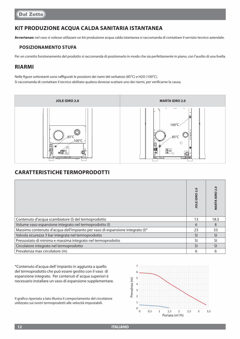
KIT PRODUZIONE ACQUA CALDA SANITARIA ISTANTANEAAvvertenze: nel caso si volesse utilizzare un kit produzione acqua calda istantanea si raccomanda di contattare il servizio tecnico aziendale.
POSIZIONAMENTO STUFA
Per un corretto funzionamento del prodotto si raccomanda di posizionarlo in modo che sia perfettamente in piano, con l’ausilio di una livella.
RIARMI
Nelle �gure sottostanti sono ra�gurati le posizioni dei riami del serbatoio (85°C) e H2O (100°C).Si raccomanda di contattare il tecnico abilitato qualora dovesse scattare uno dei riarmi, per veri�carne la causa.
*Contenuto d’acqua dell’ impianto in aggiunta a quello del termoprodotto che può essere gestito con il vaso di espansione integrato. Per contenuti d’ acqua superiori è necessario installare un vaso di espansione supplementare.
Il gra�co riportato a lato illustra il comportamento del circolatore utilizzato sui nostri termoprodotti alle velocità impostabili.
Prev
alnz
a (m
)
CARATTERISTICHE TERMOPRODOTTI
JOLE
IDRO
2.0
MA
RTA
IDRO
2.0
Contenuto d’acqua scambiatore (l) del termoprodotto 13 18.5Volume vaso espansione integrato nel termoprodotto (l) 6 8Massimo contenuto d’acqua dell’impianto per vaso di espansione integrato (l)* 23 33Valvola sicurezza 3 bar integrata nel termoprodotto SI SIPressostato di minima e massima integrato nel termoprodotto SI SICircolatore integrato nel termoprodotto SI SIPrevalenza max circolatore (m) 6 6
Portata (m3/h)
12
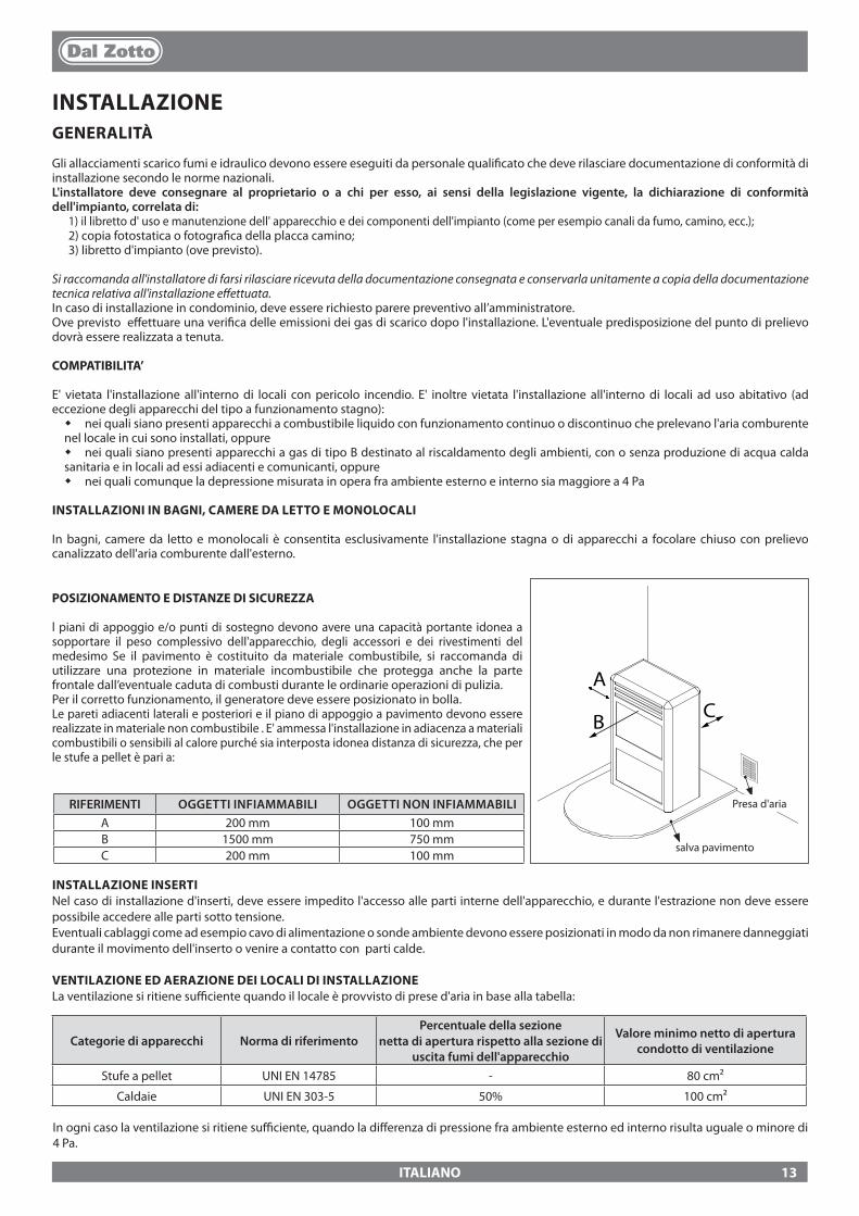
A
CB
ITALIANO
Presa d'ariaRIFERIMENTI OGGETTI INFIAMMABILI OGGETTI NON INFIAMMABILIA 200 mm 100 mmB 1500 mm 750 mmC 200 mm 100 mm
salva pavimento
INSTALLAZIONE INSERTINel caso di installazione d'inserti, deve essere impedito l'accesso alle parti interne dell'apparecchio, e durante l'estrazione non deve essere possibile accedere alle parti sotto tensione.Eventuali cablaggi come ad esempio cavo di alimentazione o sonde ambiente devono essere posizionati in modo da non rimanere danneggiati durante il movimento dell'inserto o venire a contatto con parti calde.
VENTILAZIONE ED AERAZIONE DEI LOCALI DI INSTALLAZIONELa ventilazione si ritiene su�ciente quando il locale è provvisto di prese d'aria in base alla tabella:
Categorie di apparecchi Norma di riferimentoPercentuale della sezione
netta di apertura rispetto alla sezione di uscita fumi dell'apparecchio
Valore minimo netto di apertura condotto di ventilazione
Stufe a pellet UNI EN 14785 - 80 cm²
Caldaie UNI EN 303-5 50% 100 cm²
In ogni caso la ventilazione si ritiene su�ciente, quando la di�erenza di pressione fra ambiente esterno ed interno risulta uguale o minore di 4 Pa.
INSTALLAZIONEGENERALITÀ
Gli allacciamenti scarico fumi e idraulico devono essere eseguiti da personale quali�cato che deve rilasciare documentazione di conformità di installazione secondo le norme nazionali.L'installatore deve consegnare al proprietario o a chi per esso, ai sensi della legislazione vigente, la dichiarazione di conformità dell'impianto, correlata di:
1) il libretto d' uso e manutenzione dell' apparecchio e dei componenti dell'impianto (come per esempio canali da fumo, camino, ecc.);2) copia fotostatica o fotogra�ca della placca camino;3) libretto d'impianto (ove previsto).
Si raccomanda all'installatore di farsi rilasciare ricevuta della documentazione consegnata e conservarla unitamente a copia della documentazione tecnica relativa all'installazione e�ettuata.In caso di installazione in condominio, deve essere richiesto parere preventivo all’amministratore.Ove previsto e�ettuare una veri�ca delle emissioni dei gas di scarico dopo l'installazione. L'eventuale predisposizione del punto di prelievo dovrà essere realizzata a tenuta.
COMPATIBILITA’
E' vietata l'installazione all'interno di locali con pericolo incendio. E' inoltre vietata l'installazione all'interno di locali ad uso abitativo (ad eccezione degli apparecchi del tipo a funzionamento stagno):
� nei quali siano presenti apparecchi a combustibile liquido con funzionamento continuo o discontinuo che prelevano l'aria comburente nel locale in cui sono installati, oppure
� nei quali siano presenti apparecchi a gas di tipo B destinato al riscaldamento degli ambienti, con o senza produzione di acqua calda sanitaria e in locali ad essi adiacenti e comunicanti, oppure
� nei quali comunque la depressione misurata in opera fra ambiente esterno e interno sia maggiore a 4 Pa
INSTALLAZIONI IN BAGNI, CAMERE DA LETTO E MONOLOCALI
In bagni, camere da letto e monolocali è consentita esclusivamente l'installazione stagna o di apparecchi a focolare chiuso con prelievo canalizzato dell'aria comburente dall'esterno.
POSIZIONAMENTO E DISTANZE DI SICUREZZA
l piani di appoggio e/o punti di sostegno devono avere una capacità portante idonea a sopportare il peso complessivo dell'apparecchio, degli accessori e dei rivestimenti del medesimo Se il pavimento è costituito da materiale combustibile, si raccomanda di utilizzare una protezione in materiale incombustibile che protegga anche la parte frontale dall’eventuale caduta di combusti durante le ordinarie operazioni di pulizia.Per il corretto funzionamento, il generatore deve essere posizionato in bolla.Le pareti adiacenti laterali e posteriori e il piano di appoggio a pavimento devono essere realizzate in materiale non combustibile . E' ammessa l'installazione in adiacenza a materiali combustibili o sensibili al calore purché sia interposta idonea distanza di sicurezza, che per le stufe a pellet è pari a:
13
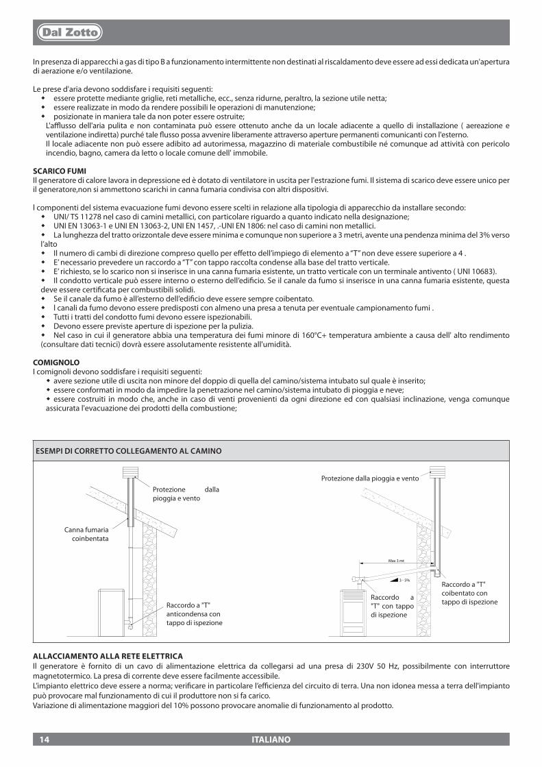
3 - 5%
Max 3 mt
ITALIANO
ESEMPI DI CORRETTO COLLEGAMENTO AL CAMINO
In presenza di apparecchi a gas di tipo B a funzionamento intermittente non destinati al riscaldamento deve essere ad essi dedicata un'apertura di aerazione e/o ventilazione.
Le prese d'aria devono soddisfare i requisiti seguenti: � essere protette mediante griglie, reti metalliche, ecc., senza ridurne, peraltro, la sezione utile netta; � essere realizzate in modo da rendere possibili le operazioni di manutenzione; � posizionate in maniera tale da non poter essere ostruite;L'a�usso dell'aria pulita e non contaminata può essere ottenuto anche da un locale adiacente a quello di installazione ( aereazione e ventilazione indiretta) purché tale �usso possa avvenire liberamente attraverso aperture permanenti comunicanti con l'esterno.Il locale adiacente non può essere adibito ad autorimessa, magazzino di materiale combustibile né comunque ad attività con pericolo incendio, bagno, camera da letto o locale comune dell' immobile.
SCARICO FUMIIl generatore di calore lavora in depressione ed è dotato di ventilatore in uscita per l'estrazione fumi. Il sistema di scarico deve essere unico per il generatore,non si ammettono scarichi in canna fumaria condivisa con altri dispositivi.
l componenti del sistema evacuazione fumi devono essere scelti in relazione alla tipologia di apparecchio da installare secondo: � UNI/ TS 11278 nel caso di camini metallici, con particolare riguardo a quanto indicato nella designazione; � UNI EN 13063-1 e UNI EN 13063-2, UNI EN 1457, .-UNI EN 1806: nel caso di camini non metallici. � La lunghezza del tratto orizzontale deve essere minima e comunque non superiore a 3 metri, avente una pendenza minima del 3% verso
l’alto � Il numero di cambi di direzione compreso quello per e�etto dell’impiego di elemento a “T” non deve essere superiore a 4 . � E’ necessario prevedere un raccordo a “T” con tappo raccolta condense alla base del tratto verticale. � E’ richiesto, se lo scarico non si inserisce in una canna fumaria esistente, un tratto verticale con un terminale antivento ( UNI 10683). � Il condotto verticale può essere interno o esterno dell’edi�cio. Se il canale da fumo si inserisce in una canna fumaria esistente, questa
deve essere certi�cata per combustibili solidi. � Se il canale da fumo è all’esterno dell’edi�cio deve essere sempre coibentato. � l canali da fumo devono essere predisposti con almeno una presa a tenuta per eventuale campionamento fumi . � Tutti i tratti del condotto fumi devono essere ispezionabili. � Devono essere previste aperture di ispezione per la pulizia. � Nel caso in cui il generatore abbia una temperatura dei fumi minore di 160°C+ temperatura ambiente a causa dell' alto rendimento
(consultare dati tecnici) dovrà essere assolutamente resistente all'umidità.
COMIGNOLOI comignoli devono soddisfare i requisiti seguenti:
� avere sezione utile di uscita non minore del doppio di quella del camino/sistema intubato sul quale è inserito; � essere conformati in modo da impedire la penetrazione nel camino/sistema intubato di pioggia e neve; � essere costruiti in modo che, anche in caso di venti provenienti da ogni direzione ed con qualsiasi inclinazione, venga comunque
assicurata l'evacuazione dei prodotti della combustione;
Protezione dalla pioggia e vento
Raccordo a "T" anticondensa con tappo di ispezione
Canna fumaria coinbentata
Raccordo a "T" coibentato con tappo di ispezione
Protezione dalla pioggia e vento
Raccordo a "T" con tappo di ispezione
ALLACCIAMENTO ALLA RETE ELETTRICAIl generatore è fornito di un cavo di alimentazione elettrica da collegarsi ad una presa di 230V 50 Hz, possibilmente con interruttore magnetotermico. La presa di corrente deve essere facilmente accessibile.L’impianto elettrico deve essere a norma; veri�care in particolare l’e�cienza del circuito di terra. Una non idonea messa a terra dell'impianto può provocare mal funzionamento di cui il produttore non si fa carico. Variazione di alimentazione maggiori del 10% possono provocare anomalie di funzionamento al prodotto.
14
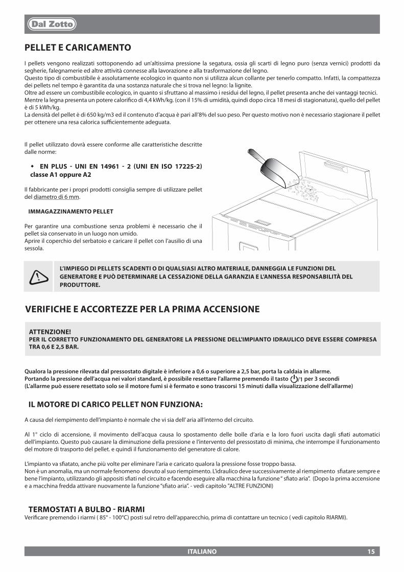
ITALIANO
PELLET E CARICAMENTOI pellets vengono realizzati sottoponendo ad un’altissima pressione la segatura, ossia gli scarti di legno puro (senza vernici) prodotti da segherie, falegnamerie ed altre attività connesse alla lavorazione e alla trasformazione del legno.Questo tipo di combustibile è assolutamente ecologico in quanto non si utilizza alcun collante per tenerlo compatto. Infatti, la compattezza dei pellets nel tempo è garantita da una sostanza naturale che si trova nel legno: la lignite.Oltre ad essere un combustibile ecologico, in quanto si sfruttano al massimo i residui del legno, il pellet presenta anche dei vantaggi tecnici.Mentre la legna presenta un potere calori�co di 4,4 kWh/kg. (con il 15% di umidità, quindi dopo circa 18 mesi di stagionatura), quello del pellet è di 5 kWh/kg.La densità del pellet è di 650 kg/m3 ed il contenuto d’acqua è pari all’8% del suo peso. Per questo motivo non è necessario stagionare il pellet per ottenere una resa calorica su�cientemente adeguata.
L’IMPIEGO DI PELLETS SCADENTI O DI QUALSIASI ALTRO MATERIALE, DANNEGGIA LE FUNZIONI DEL GENERATORE E PUÒ DETERMINARE LA CESSAZIONE DELLA GARANZIA E L’ANNESSA RESPONSABILITÀ DEL PRODUTTORE.
Il pellet utilizzato dovrà essere conforme alle caratteristiche descritte dalle norme:
� EN PLUS - UNI EN 14961 - 2 (UNI EN ISO 17225-2) classe A1 oppure A2
Il fabbricante per i propri prodotti consiglia sempre di utilizzare pellet del diametro di 6 mm.
IMMAGAZZINAMENTO PELLET
Per garantire una combustione senza problemi è necessario che il pellet sia conservato in un luogo non umido.Aprire il coperchio del serbatoio e caricare il pellet con l’ausilio di una sessola.
VERIFICHE E ACCORTEZZE PER LA PRIMA ACCENSIONE
ATTENZIONE!PER IL CORRETTO FUNZIONAMENTO DEL GENERATORE LA PRESSIONE DELL'IMPIANTO IDRAULICO DEVE ESSERE COMPRESA TRA 0,6 E 2,5 BAR.
Qualora la pressione rilevata dal pressostato digitale è inferiore a 0,6 o superiore a 2,5 bar, porta la caldaia in allarme.Portando la pressione dell'acqua nei valori standard, è possibile resettare l'allarme premendo il tasto /1 per 3 secondi(L’allarme può essere resettato solo se il motore fumi si è fermato e sono trascorsi 15 minuti dalla visualizzazione dell’allarme)
IL MOTORE DI CARICO PELLET NON FUNZIONA:
A causa del riempimento dell’impianto è normale che vi sia dell’ aria all’interno del circuito.
Al 1° ciclo di accensione, il movimento dell’acqua causa lo spostamento delle bolle d’aria e la loro fuori uscita dagli s�ati automatici dell’impianto. Questo può causare la diminuzione della pressione e l’intervento del pressostato di minima, che interrompe il funzionamento del motore di trasporto del pellet. e quindi il funzionamento del generatore di calore.
L’impianto va s�atato, anche più volte per eliminare l’aria e caricato qualora la pressione fosse troppo bassa.Non è un anomalia, ma un normale fenomeno dovuto al suo riempimento. L’idraulico deve successivamente al riempimento s�atare sempre e bene l’impianto, utilizzando gli appositi s�ati nel circuito e facendo eseguire alla macchina la funzione “ s�ato aria”. (Dopo la prima accensione e a macchina fredda attivare nuovamente la funzione “s�ato aria”. - vedi capitolo "ALTRE FUNZIONI)
TERMOSTATI A BULBO - RIARMIVeri�care premendo i riarmi ( 85° - 100°C) posti sul retro dell’apparecchio, prima di contattare un tecnico ( vedi capitolo RIARMI).
15
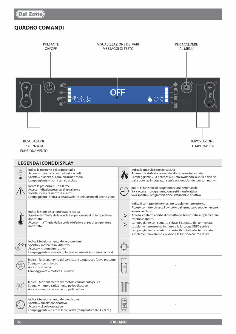
12
3
4
5
6
OFF
ITALIANO
QUADRO COMANDI
PULSANTE ON/OFF
VISUALIZZAZIONE DEI VARI MESSAGGI DI TESTO
PER ACCEDERE AL MENÙ’
IMPOSTAZIONE TEMPERATURA
REGOLAZIONE POTENZA DI
FUNZIONAMENTO
LEGENDA ICONE DISPLAYIndica la ricezione del segnale radioAccesa = durante la comunicazione radioSpenta = assenza di comunicazione radioLampeggiante = porta seriale esclusa
Indica la modulazione della stufaAccesa = la stufa sta lavorando alla potenza impostataLampeggiante = la potenza a cui sta lavorando la stufa è diversa dalla potenza impostata, la stufa sta modulando (per vari motivi)
Indica la presenza di un allarme.Accesa: indica la presenza di un allarmeSpenta: indica l’assenza di allarmiLampeggiante: indica la disattivazione del sensore di depressione.
Indica la funzione di programmazione settimanaleSpia accesa = programmazione settimanale attivaSpia spenta = programmazione settimanale disattiva
Indica lo stato della temperatura acquaSpento= la T° letta dalla sonda è superiore al set di temperatura impostatoAcceso = la T° letta dalla sonda è inferiore al set di temperatura impostato
Indica il contatto del termostato supplementare esternoAcceso contatto chiuso: il contatto del termostato supplementare esterno è chiuso.Acceso contatto aperto: il contatto del termostato supplementare esterno è aperto.Lampeggiante con contatto chiuso: il contatto del termostato supplementare esterno è chiuso e la funzione STBY è attivaLampeggiante con contatto aperto: il contatto del termostato supplementare esterno è aperto e la funzione STBY è attiva
Indica il funzionamento del motore fumi.Spento = motore fumi disattivoAcceso = motore fumi attivoLampeggiante = avaria (contattare servizio di assistenza tecnica)
-
Indica il funzionamento del ventilatore tangenziale (dove presente)Spento = non in lavoroAcceso = in lavoroLampeggiante = motore al minimo
-
Indica il funzionamento del motore caricamento pelletSpenta = motore caricamento pellet disattivoAccesa = motore caricamento pellet attivo
-
Indica il funzionamento del circolatoreSpenta = circolatore disattivoAccesa = circolatore attivoLampeggiante = è attiva la sicurezza (temperatura H2O > 85°C)
-
16
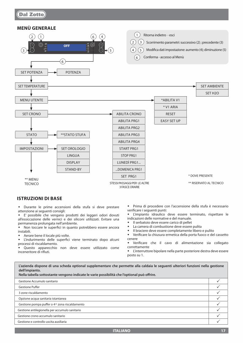
OFF12
3
4
5
6
1
2 3
4 5
6
12
3
46
5
6
ITALIANO
MENÙ GENERALERitorna indietro - esci
Scorrimento parametri: successivo (2) ; precedente (3) Modi�ca dati impostazione: aumento (4); diminuzione (5)
Conferma - accesso al Menù
SET POTENZA POTENZA
SET TEMPERATURE SET AMBIENTE
SET H2O
MENU UTENTE *ABILITA V1
* V1 ARIA
SET CRONO ABILITA CRONO RESET
ABILITA PRG1 EASY SET UP
ABILITA PRG2
STATO **STATO STUFA ABILITA PRG3
ABILITA PRG4
IMPOSTAZIONI SET OROLOGIO START PRG1
LINGUA STOP PRG1
DISPLAY LUNEDÌ PRG1...
STAND-BY ...DOMENICA PRG1
** MENUTECNICO
SET PRG1 * DOVE PRESENTE
** RISERVATO AL TECNICOSTESSI PASSAGGI PER LE ALTRE 3 FASCE ORARIE
L'azienda dispone di una scheda optional supplementare che permette alla caldaia le seguenti ulteriori funzioni nella gestione dell’impianto. Nella tabella sottostante vengono indicate le varie possibilità che l’optional può o�rire.
Gestione Accumulo sanitario pGestione Pu�er p3 zone riscaldamento pOpzione acqua sanitaria istantanea pGestione pompa pu�er o 4^ zona riscaldamento p
Gestione antilegionella per accumulo sanitario p Gestione crono accumulo sanitario p Gestione e controllo uscita ausiliaria p
ISTRUZIONI DI BASE
� Durante le prime accensioni della stufa si deve prestare attenzione ai seguenti consigli:� E’ possibile che vengano prodotti dei leggeri odori dovuti all’essiccazione delle vernici e dei siliconi utilizzati. Evitare una permanenza prolungata nell'ambiente.� Non toccare le super�ci in quanto potrebbero essere ancora instabili.� Aerare bene il locale più volte.� L’indurimento delle super�ci viene terminato dopo alcuni processi di riscaldamento.� Questo apparecchio non deve essere utilizzato come inceneritore di ri�uti.
� Prima di procedere con l’accensione della stufa è necessario veri�care i seguenti punti:� L'impianto idraulico deve essere terminato, rispettare le indicazioni delle normative e del manuale.� Il serbatoio deve essere carico di pellet� La camera di combustione deve essere pulita� Il braciere deve essere completamente libero e pulito� Veri�care la chiusura ermetica della porta fuoco e del cassetto cenere� Veri�care che il cavo di alimentazione sia collegato correttamente� L'interruttore bipolare nella parte posteriore destra deve essere posto su 1.
17

ITALIANO
IL TELECOMANDOMediante il telecomando sì ha la possibilità di regolare tutto ciò che normalmente è possibile eseguire con il display Lcd.Nella tabella sottostante in dettaglio le varie funzioni:
INFO
1
2
3
4
5
6
7
8
9
10
11 12 13
14 15 16
1 ON / OFF Premendo il tasto per tre secondi la stufa andrà in accensione o in spegnimento
2 INCREMENTO POTENZA Premendo il tasto posso incrementare la potenza di funzionamento
3 DECREMENTO POTENZA Premendo il tasto posso decrementare la potenza di funzionamento
4 INCREMENTO T° Il tasto permette di aumentare il set temperatura
5 DECREMENTO T° Il tasto permette di decrementare il set temperatura
6 ABILITA / DISABILITA CRONO Premendo il tasto una volta posso abilitare o disabilitare il crono
7 ABILITA SPEGNIMENTO RITARDATO
Il tasto permette di ritardare lo spegnimento programmandone il ritardo. Per esempio se imposto lo spegnimento fra un’ ora la stufa in automatico si spegnerà allo scadere del tempo impostato, visualizzando ogni minuto il conto alla rovescia per lo spegnimento automatico ritardato.
8 MENÙ Il tasto mi permette di entrare nel menù utente e tecnico (il menù tecnico è riservato all’assistenza)
9 INCREMENTA Il tasto permette di aumentare il set temperatura
10 TASTO ESC Il tasto permette di uscire da qualsiasi programmazione o visualizzazione riportando il menù iniziale, senza memorizzare i dati
11 INDIETRO Il tasto retrocede nella visualizzazione dei vari menù
12 TASTO CONFERMA Il tasto conferma le regolazioni e�ettuate in fase di programmazione menù utente
13 AVANTI Il tasto serve per proseguire nei vari menù
14 ABILITA FUNZIONE F1 Tasto predisposto per applicazioni future
15 DECREMENTA Il tasto serve per decrementare il valore da impostare
16 STATO STUFA Premendo il tasto viene visualizzato lo stato generale dello stato stufa
TIPOLOGIA E SOSTITUZIONE DELLE BATTERIE
Le batterie sono alloggiate nella parte inferiore del telecomando. Per sostituirla è necessario estrarre il porta-batteria, rimuovere o inserire la pila seguendo la simbologia impressa sul telecomando e sulla batteria stessa.Per il funzionamento è necessaria n° 1 Batterie tampone a litio CR2025 da 3V
Le pile usate contengono metalli nocivi per l’ambiente,quindi devono essere smaltite separatamente in appositi contenitori.
Nota bene: i numeri ra�gurati sul telecomando sono a scopo illustrativo e non sono presenti sul telecomando fornito con il prodotto.
SE IL TELECOMANDO È SPENTO PER ASSENZA DI BATTERIE, È POSSIBILE COMANDARE LA STUFA DAL PANNELLO COMANDI, POSTO NELLA PARTE SUPERIORE DELLA STUFA. DURANTE L’OPERAZIONE DI SOSTITUZIONE PRESTARE ATTENZIONE ALLE POLARITÀ SEGUENDO LA SIMBOLOGIA IMPRESSA SUL VANO INTERNO DEL TELECOMANDO.
J
ALL CLEAN CHECK UP
NEL CASO SI PRESENTASSE "ALL CLEAN CHECK UP" E' NECESSARIO ASSICURARSI CHE IL FONDO BRACIERE SIA LIBERO DA RESIDUI O INCROSTAZIONI. I FORI PRESENTI NEL FONDO DEVONO ESSERE COMPLETAMENTE LIBERI, PER ASSICURARE UNA CORRETTA COMBUSTIONE. È POSSIBILE UTILIZZARE LA FUNZIONE"REGOLAZIONE CARICO PELLET" PER ADEGUARE LA COMBUSTIONE IN BASE ALLE ESIGENZE DESCRITTE. NEL CASO PERSISTA LA SEGNALAZIONE D'ALLARME, E SONO STATE VERIFICARE LE CONDIZIONI SOPRA ELENCATE, CONTATTARE IL CENTRO ASSISTENZA ABILITATO.
FONDO BRACIERE
18
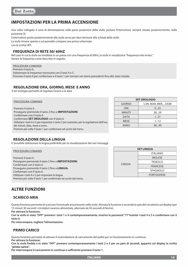
ITALIANO
REGOLAZIONE ORA, GIORNO, MESE E ANNOIl set orologio permette di regolare l’orario e la data
PROCEDURA COMANDI
Premere il tasto 6 .Proseguire premendo il tasto 2 �no a IMPOSTAZIONI.Confermare con il tasto 6.Proseguire premendo il tasto 2 �no a LINGUA.Confermare con il tasto 6.Utilizzare i tasti 4 o 5 per impostare la lingua.Premere più volte il tasto 1 per confermare ed uscire dal menu.
SET LINGUA
LINGUA
ITALIANO
INGLESE
TEDESCO
FRANCESE
SPAGNOLO
PORTOGHESE
IMPOSTAZIONI PER LA PRIMA ACCENSIONE
Una volta collegato il cavo di alimentazione nella parte posteriore della stufa, portare l’interruttore, sempre situato posteriormente, nella posizione (I).L’interruttore posto posteriormente alla stufa serve per dare tensione alla scheda della stufa.La stufa rimane spenta e sul pannello compare una prima schermatacon la scritta OFF.
ALTRE FUNZIONI
SCARICO ARIA
Questa funziona permette di scaricare l'eventuale aria presente nella stufa. Attivata la funzione si accende la spia del circolatore sul display (per 15 minuti 30 secondi i circolatori saranno alimentate, alternate da 30 secondi di fermo).Per attivare la funzione:Con la stufa in stato "OFF" premere i tasti 1 e 4 contemporaneamente, inserire la password "77"tramite i tasti 4 e 5 e confermare con il tasto 6. Per interrompere, togliere l'alimentazione.
PRIMO CARICO
Questa funzione permette di attivare il motoriduttore di caricamento del pellet per un funzionamento in continuo. Per attivare la funzione:Con la stufa fredda e in stato "OFF" premere contemporaneamente i tasti 2 e 5 per un paio di secondi, apparirà sul display la scritta “primo carico”.Per interrompere il caricamento in continuo e sufficiente premere il tasto 1.
PROCEDURA COMANDI
Premere il tasto 6 .Proseguire premendo il tasto 2 �no a IMPOSTAZIONI.Confermare con il tasto 6.Confermare SET OROLOGIO con il tasto 6.Utilizzare i tasti 4 o 5 per impostare e tasto 2 per avanzare, per la regolazione dell'ora, dei minuti, data, mese e anno.Premere più volte il tasto 1 per confermare ed uscire dal menu.
SET OROLOGIOGIORNO LUN, MAR, MER, ...DOM
ORE 0...23
MINUTI 00...59
DATA 1...31
MESE 1...12
ANNO 00...99
REGOLAZIONE DELLA LINGUAE’ possibile selezionare la lingua preferibile per la visualizzazione dei vari messaggi
FREQUENZA DI RETE 50/ 60HZNel caso in cui la stufa sia installata in un paese con una frequenza di 60Hz, la stufa in visualizzerà "frequenza rete errata ".Variare la frequenza come descritto in seguito.
PROCEDURA COMANDIPremere il tasto 6, Selezionare la frequenza necessaria con il tasti 4 o 5.Premere il tasto 6 per confermare e il tasto 1 per tornare nei menù precedenti �no allo stato iniziale.
19

ITALIANO
FUNZIONAMENTO E LOGICA
ACCENSIONEUna volta veri�cati i punti in precedenza elencati, premere il tasto 1 per tre secondi per accendere la stufa. Per la fase di accensione sono a disposizione 15 minuti, dopo l'avvenuta accensione e raggiungimento della temperatura di controllo, la stufa interrompe la fase di accensione e passa in AVVIAMENTO.
AVVIAMENTONella fase di avviamento la stufa stabilizza la combustione, aumentando progressivamente la combustione, per poi avviare successivamente la ventilazione, e passando in LAVORO.
LAVORONella fase di lavoro la stufa si porterà nel set potenza impostato, vedi voce seguente.
REGOLAZIONE SET POTENZAImpostare la potenza di funzionamento da 1 a 5 (impostabili tramite i tasti 2 - 3).Potenza 1 = livello minimo - Potenza 5 = livello massimo.
REGOLAZIONE SET TEMPERATURA H2OImpostare la temperatura caldaia da 65 - 80°C (impostabili tramite i tasti 4 - 5).
FUNZIONAMENTO DEL CIRCOLATOREIl circolatore attiva la circolazione dell’acqua quando nella stufa la t° dell’acqua raggiunge circa 60° C. Essendo il circolatore sempre in funzionamento sopra i 60°, si consiglia una zona di riscaldamento sempre aperta per rendere più omogeneo il funzionamento del prodotto, ed evitare blocchi per sovratemperatura, di solito questa zona viene de�nita “zona di sicurezza”.
TEMPERATURA AMBIENTE (nei modelli previsti)È possibile attivare/ disattivare la ventilazione frontale e controllare la temperatura ambiente tramite la Sonda ambiente (di serie). (Vedi capitolo "abilita aria" nelle pagine seguenti.)
PULIZIA BRACIERELa stufa durante la fase di lavoro ha un contatore interno, il quale dopo un tempo prestabilito e�ettua una pulizia del braciere.Questa fase verrà ra�gurata sul display, porterà la stufa ad una potenza inferiore e aumenterà il motore fumi per un tempo determinato in programmazione. Terminata la fase di pulizia, la stufa proseguirà il suo lavoro portandosi nuovamente alla potenza selezionata.
MODULAZIONE e H-OFFA mano a mano che la temperatura dell’acqua si avvicina al set impostato la caldaia inizia a modulare portandosi automaticamente alla minima potenza. Se la temperatura aumenta superando il set impostato si porterà automaticamente in spegnimento segnalando H-OFF, per riaccendersi sempre in automatico appena la temperatura scende al di sotto del set impostato.
SPEGNIMENTOPremere il tasto 1 per tre secondi.Eseguita questa operazione l’apparecchio entra automaticamente nella fase di spegnimento, bloccando la fornitura dei pellets.Il motore di aspirazione dei fumi e il motore della ventilazione aria calda resteranno accesi �no a che la temperatura della stufa non sarà scesa sotto i parametri di fabbrica.
RIACCENSIONELa riaccensione sia in automatico che manuale della stufa è possibile, solo quando le condizioni del ciclo di ra�reddamento e il timer preimpostato sono state assolte.
J MANCATA ACCENSIONE
LA PRIMA ACCENSIONE POTREBBE ANCHE FALLIRE, DATO CHE LA COCLEA È VUOTA E NON SEMPRE RIESCE A CARICARE IN TEMPO IL BRACIERE DELLA NECESSARIA QUANTITÀ DI PELLET PER L’AVVIO REGOLARE DELLA FIAMMA. SE IL PROBLEMA SI VERIFICA SOLO DOPO ALCUNI MESI DI LAVORO, VERIFICARE CHE LE PULIZIE ORDINARIE, RIPORTATE SUL LIBRETTO STUFA, SIANO STATE ESEGUITE CORRETTAMENTE
NON UTILIZZARE ALCUN LIQUIDO INFIAMMABILE PER L’ ACCENSIONE!IN FASE DI RIEMPIMENTO NON PORTARE IL SACCO DI PELLET A CONTATTO CON LA STUFA BOLLENTE!NEL CASO DI CONTINUE MANCANTE ACCENSIONI CONTATTARE UN TECNICO AUTORIZZATO.
E' VIETATO UTILIZZARE L'APPARECCHIO PRIVO DEL DIVISORIO E/O BATTIFIAMMA (VEDI FIGURA A LATO). LA RIMOZIONE PREGIUDICA LA SICUREZZA DEL PRODOTTO E COMPORTA IL DECADIMENTO IMMEDIATO DEL PERIODO DI GARANZIA. IN CASO DI USURA O DETERIORAMENTO RICHIEDERE LA SOSTITUZIONE DEL PARTICOLARE AL SERVIZIO DI ASSISTENZA (SOSTITUZIONE CHE NON RIENTRA NELLA GARANZIA DEL PRODOTTO IN QUANTO PARTICOLARE SOGGETTO AD USURA).
DIVISORIO SUPERIORE BRACIERE
BATTIFIAMMA
20
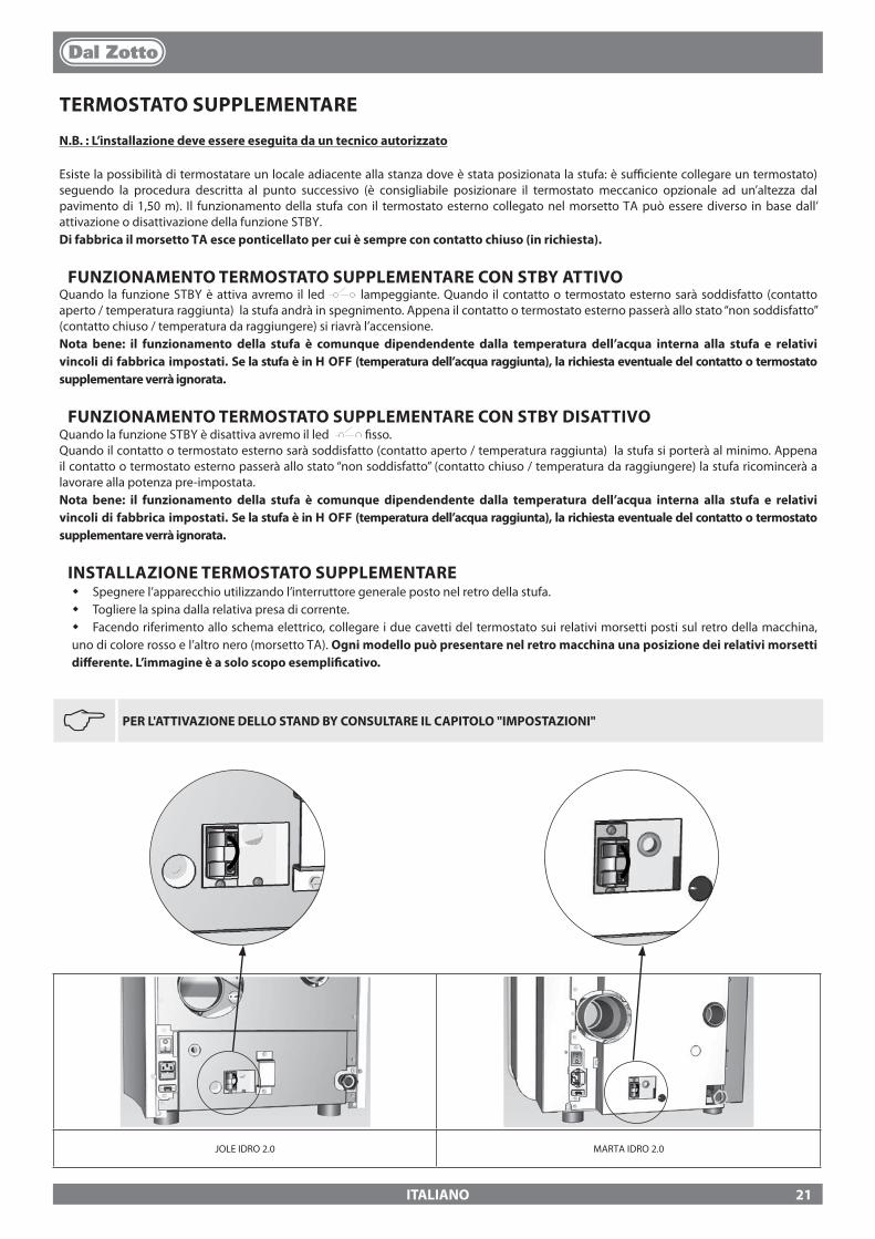
JOLE IDRO 2.0 MARTA IDRO 2.0
ITALIANO
TERMOSTATO SUPPLEMENTARE
N.B. : L’installazione deve essere eseguita da un tecnico autorizzato
Esiste la possibilità di termostatare un locale adiacente alla stanza dove è stata posizionata la stufa: è su�ciente collegare un termostato) seguendo la procedura descritta al punto successivo (è consigliabile posizionare il termostato meccanico opzionale ad un’altezza dal pavimento di 1,50 m). Il funzionamento della stufa con il termostato esterno collegato nel morsetto TA può essere diverso in base dall’ attivazione o disattivazione della funzione STBY.Di fabbrica il morsetto TA esce ponticellato per cui è sempre con contatto chiuso (in richiesta).
FUNZIONAMENTO TERMOSTATO SUPPLEMENTARE CON STBY ATTIVOQuando la funzione STBY è attiva avremo il led lampeggiante. Quando il contatto o termostato esterno sarà soddisfatto (contatto aperto / temperatura raggiunta) la stufa andrà in spegnimento. Appena il contatto o termostato esterno passerà allo stato “non soddisfatto” (contatto chiuso / temperatura da raggiungere) si riavrà l’accensione.Nota bene: il funzionamento della stufa è comunque dipendendente dalla temperatura dell’acqua interna alla stufa e relativi vincoli di fabbrica impostati. Se la stufa è in H OFF (temperatura dell’acqua raggiunta), la richiesta eventuale del contatto o termostato supplementare verrà ignorata.
FUNZIONAMENTO TERMOSTATO SUPPLEMENTARE CON STBY DISATTIVOQuando la funzione STBY è disattiva avremo il led �sso.Quando il contatto o termostato esterno sarà soddisfatto (contatto aperto / temperatura raggiunta) la stufa si porterà al minimo. Appena il contatto o termostato esterno passerà allo stato “non soddisfatto” (contatto chiuso / temperatura da raggiungere) la stufa ricomincerà a lavorare alla potenza pre-impostata. Nota bene: il funzionamento della stufa è comunque dipendendente dalla temperatura dell’acqua interna alla stufa e relativi vincoli di fabbrica impostati. Se la stufa è in H OFF (temperatura dell’acqua raggiunta), la richiesta eventuale del contatto o termostato supplementare verrà ignorata.
INSTALLAZIONE TERMOSTATO SUPPLEMENTARE� Spegnere l’apparecchio utilizzando l’interruttore generale posto nel retro della stufa.� Togliere la spina dalla relativa presa di corrente.� Facendo riferimento allo schema elettrico, collegare i due cavetti del termostato sui relativi morsetti posti sul retro della macchina, uno di colore rosso e l’altro nero (morsetto TA). Ogni modello può presentare nel retro macchina una posizione dei relativi morsetti di�erente. L’immagine è a solo scopo esempli�cativo.
J
PER L'ATTIVAZIONE DELLO STAND BY CONSULTARE IL CAPITOLO "IMPOSTAZIONI"
21
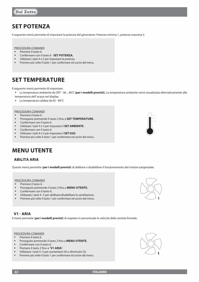
ITALIANO
SET POTENZAIl seguente menù permette di impostare la potenza del generatore. Potenza minima 1, potenza massima 5.
PROCEDURA COMANDI� Premere il tasto 6.� Confermare con il tasto 6 - SET POTENZA.� Utilizzare i tasti 4 o 5 per impostare la potenza.� Premere più volte il tasto 1 per confermare ed uscire dal menu.
SET TEMPERATUREIl seguente menù permette di impostare:� La temperatura ambiente da OFF - 06 ...40°C (per i modelli previsti). La temperatura ambiente verrà visualizzata alternativamente alla temperatura dell’ acqua nel display.� La temperatura caldaia da 65 - 80°C.
PROCEDURA COMANDI� Premere il tasto 6 .� Proseguire premendo il tasto 2 �no a SET TEMPERATURE.� Confermare con il tasto 6.� Utilizzare i tasti 4 o 5 per impostare il SET AMBIENTE.� Confermare con il tasto 6.� Utilizzare i tasti 4 o 5 per impostare il SET H2O.� Premere più volte il tasto 1 per confermare ed uscire dal menu.
MENU UTENTEABILITA ARIA
Questo menù permette (per i modelli previsti) di abilitare o disabilitare il funzionamento del motore tangenziale.
PROCEDURA COMANDI� Premere il tasto 6 .� Proseguire premendo il tasto 2 �no a MENU UTENTE.� Confermare con il tasto 6.� Utilizzare i tasti 4 -5 per abilitare/disabilitare la ventilazione.� Premere più volte il tasto 1 per confermare ed uscire dal menu. 1
V1 - ARIAIl menù permette (per i modelli previsti) di regolare in percentuale la velocità della ventola frontale.
PROCEDURA COMANDI� Premere il tasto 6 .� Proseguire premendo il tasto 2 �no a MENU UTENTE.� Confermare con il tasto 6.� Premere il tasto 2 �no a "V1 ARIA".� Utilizzare i tasti 4 -5 per aumentare (4) o diminuire (5).� Premere più volte il tasto 1 per confermare ed uscire dal menu. 1
22
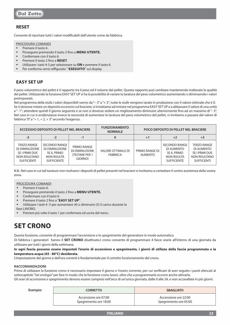
ITALIANO
PROCEDURA COMANDI� Premere il tasto 6 .� Proseguire premendo il tasto 2 �no a MENU UTENTE.� Confermare con il tasto 6.� Premere il tasto 2 �no a RESET.� Utilizzare i tasti 4-5 per selezionare su ON e premere il tasto 6.� Per conferma verrà ra�gurato " ESEGUITO" sul display
EASY SET UP
Il peso volumetrico del pellet è il rapporto tra il peso ed il volume del pellet. Questo rapporto può cambiare mantenendo inalterata la qualità del pellet. Utilizzando la funziona EASY SET UP si ha la possibilità di variare la taratura del peso volumetrico aumentando o diminuendo i valori preimpostati.Nel programma della stufa i valori disponibili vanno da “– 3” a “+ 3”; tutte le stufe vengono tarate in produzione con il valore ottimale che è 0.Se si dovesse notare un deposito eccessivo sul braciere, vi inviatiamo ad entrare nel programma EASY SET UP e a abbassare il valore di una unità a “- 1”; attendere quindi il giorno seguente e se non si dovesse vedere un miglioramento diminuire ulteriormente �no ad un massimo di “- 3”. Nel caso in cui si evidenziasse invece la necessità di aumentare la taratura del peso volumetrico del pellet, vi invitiamo a passare dal valore di fabbrica “0” a “+ 1, + 2, + 3” secondo l’esigenza.
RESET
Consente di riportare tutti i valori modi�cabili dall’utente come da fabbrica.
ECCESSIVO DEPOSITO DI PELLET NEL BRACIERE FUNZIONAMENTO NORMALE POCO DEPOSITO DI PELLET NEL BRACIERE
-3 -2 -1 0 +1 +2 +3
TERZO RANGE DI DIMINUZIONE
SE I PRIMI DUE NON RISULTANO
SUFFICIENTI
SECONDO RANGE DI DIMINUZIONE
SE IL PRIMO NON RISULTA SUFFICIENTE
PRIMO RANGE DI DIMINUZIONE (TESTARE PER 1
GIORNO)
VALORE OTTIMALE DI FABBRICA
PRIMO RANGE DI AUMENTO
SECONDO RANGE DI AUMENTO SE IL PRIMO
NON RISULTA SUFFICIENTE
TERZO RANGE DI AUMENTO
SE I PRIMI DUE NON RISULTANO
SUFFICIENTI
SET CRONOQuesta funzione, consente di programmare l’accensione e lo spegnimento del generatore in modo automatico.Di fabbrica i generatori hanno il SET CRONO disattivato.l crono consente di programmare 4 fasce orarie all’interno di una giornata da utilizzare per tutti i giorni della settimana. In ogni fascia possono essere impostati l’orario di accensione e spegnimento, i giorni di utilizzo della fascia programmata e la temperatura acqua (65 - 80°C) desiderata. L’impostazione del giorno e dell’ora correnti è fondamentale per il corretto funzionamento del crono.
RACCOMANDAZIONIPrima di utilizzare la funzione crono è necessario impostare il giorno e l’orario corrente, per cui veri�care di aver seguito i punti elencati al sottocapitolo “Set orologio” per fare in modo che la funzione crono lavori, oltre che a programmarla occorre anche attivarla. Gli orari di accensione e spegnimento devono essere compresi nell’arco di un’unica giornata, dalle 0 alle 24, e non accavallate in più giorni.
CORRETTO SBAGLIATO
Accensione ore 07:00Spegnimento ore 18:00
Accensione ore 22:00Spegnimento ore 05:00
Esempio:
N.B.: Nel caso in cui tali tarature non risolvano i depositi di pellet presenti nel braciere vi invitiamo a contattare il centro assistenza della vostra zona.
PROCEDURA COMANDI� Premere il tasto 6.� Proseguire premendo il tasto 2 �no a MENU UTENTE.� Confermare con il tasto 6.� Premere il tasto 2 �no a "EASY SET UP".� Utilizzare i tasti 4 -5 per aumentare (4) o diminuire (5) il carico durante la fase LAVORO.� Premere più volte il tasto 1 per confermare ed uscire dal menu.
23
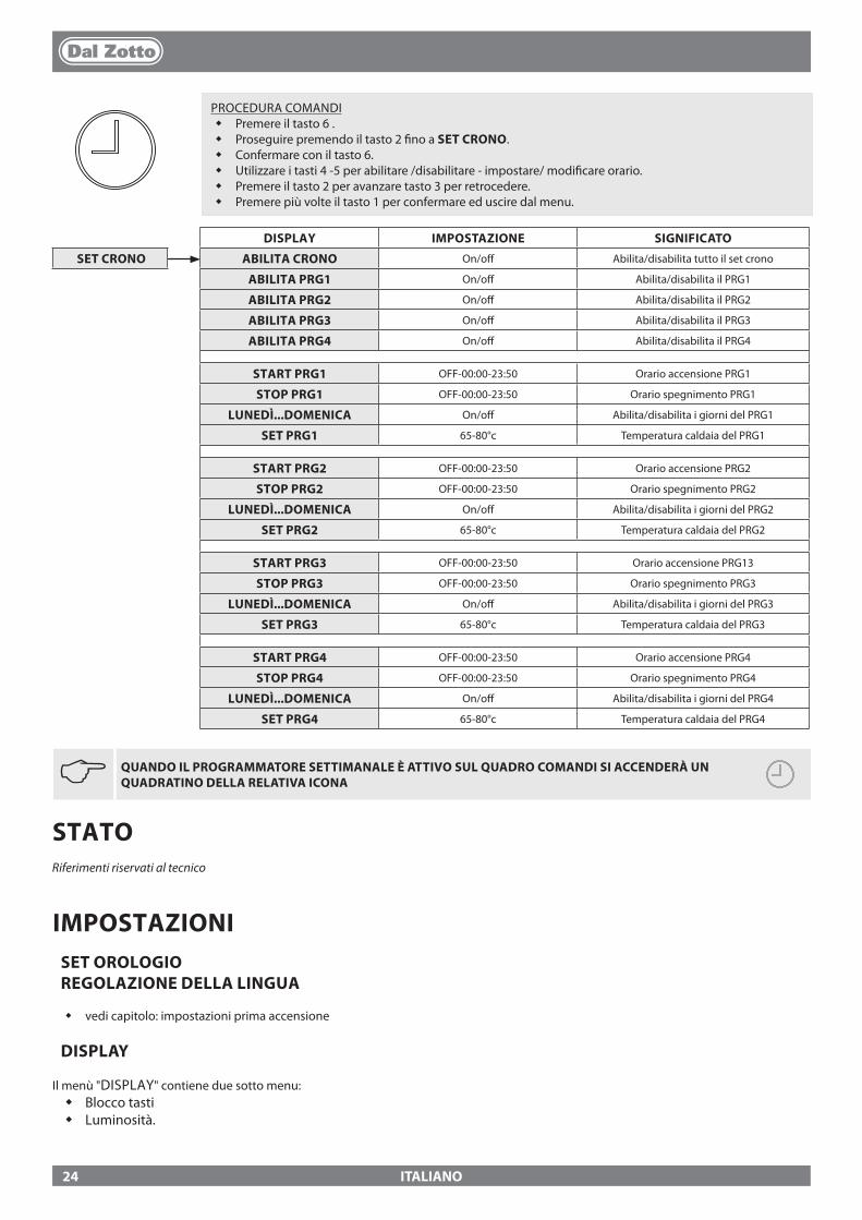
ITALIANO
JQUANDO IL PROGRAMMATORE SETTIMANALE È ATTIVO SUL QUADRO COMANDI SI ACCENDERÀ UN QUADRATINO DELLA RELATIVA ICONA
DISPLAY IMPOSTAZIONE SIGNIFICATO
SET CRONO ABILITA CRONO On/o� Abilita/disabilita tutto il set crono
ABILITA PRG1 On/o� Abilita/disabilita il PRG1
ABILITA PRG2 On/o� Abilita/disabilita il PRG2
ABILITA PRG3 On/o� Abilita/disabilita il PRG3
ABILITA PRG4 On/o� Abilita/disabilita il PRG4
START PRG1 OFF-00:00-23:50 Orario accensione PRG1
STOP PRG1 OFF-00:00-23:50 Orario spegnimento PRG1
LUNEDÌ...DOMENICA On/o� Abilita/disabilita i giorni del PRG1
SET PRG1 65-80°c Temperatura caldaia del PRG1
START PRG2 OFF-00:00-23:50 Orario accensione PRG2
STOP PRG2 OFF-00:00-23:50 Orario spegnimento PRG2
LUNEDÌ...DOMENICA On/o� Abilita/disabilita i giorni del PRG2
SET PRG2 65-80°c Temperatura caldaia del PRG2
START PRG3 OFF-00:00-23:50 Orario accensione PRG13
STOP PRG3 OFF-00:00-23:50 Orario spegnimento PRG3
LUNEDÌ...DOMENICA On/o� Abilita/disabilita i giorni del PRG3
SET PRG3 65-80°c Temperatura caldaia del PRG3
START PRG4 OFF-00:00-23:50 Orario accensione PRG4
STOP PRG4 OFF-00:00-23:50 Orario spegnimento PRG4
LUNEDÌ...DOMENICA On/o� Abilita/disabilita i giorni del PRG4
SET PRG4 65-80°c Temperatura caldaia del PRG4
PROCEDURA COMANDI� Premere il tasto 6 .� Proseguire premendo il tasto 2 �no a SET CRONO.� Confermare con il tasto 6.� Utilizzare i tasti 4 -5 per abilitare /disabilitare - impostare/ modi�care orario.� Premere il tasto 2 per avanzare tasto 3 per retrocedere.� Premere più volte il tasto 1 per confermare ed uscire dal menu.
STATORiferimenti riservati al tecnico
IMPOSTAZIONISET OROLOGIO REGOLAZIONE DELLA LINGUA
� vedi capitolo: impostazioni prima accensione
DISPLAY
Il menù "DISPLAY" contiene due sotto menu:� Blocco tasti� Luminosità.
24
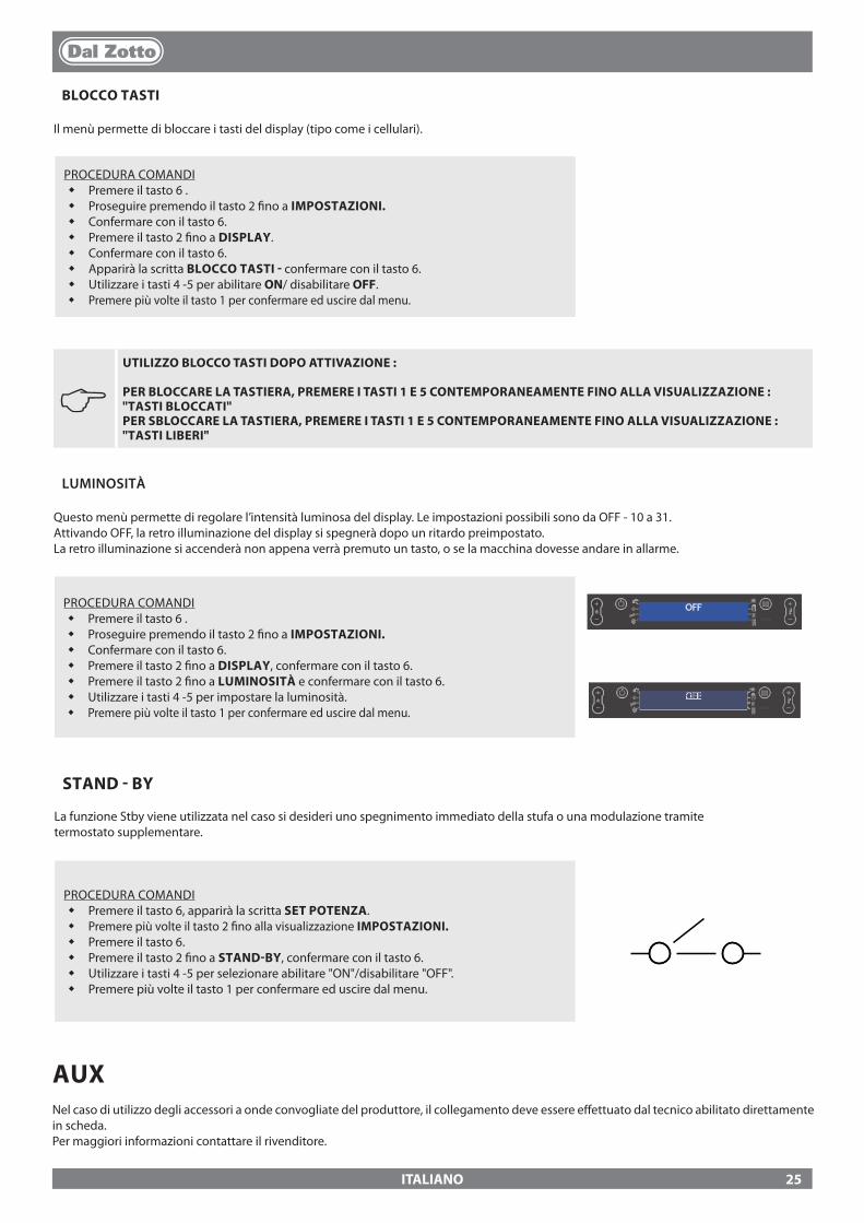
ITALIANO
J UTILIZZO BLOCCO TASTI DOPO ATTIVAZIONE :
PER BLOCCARE LA TASTIERA, PREMERE I TASTI 1 E 5 CONTEMPORANEAMENTE FINO ALLA VISUALIZZAZIONE : "TASTI BLOCCATI" PER SBLOCCARE LA TASTIERA, PREMERE I TASTI 1 E 5 CONTEMPORANEAMENTE FINO ALLA VISUALIZZAZIONE : "TASTI LIBERI"
LUMINOSITÀ
Questo menù permette di regolare l’intensità luminosa del display. Le impostazioni possibili sono da OFF - 10 a 31.Attivando OFF, la retro illuminazione del display si spegnerà dopo un ritardo preimpostato. La retro illuminazione si accenderà non appena verrà premuto un tasto, o se la macchina dovesse andare in allarme.
PROCEDURA COMANDI� Premere il tasto 6 .� Proseguire premendo il tasto 2 �no a IMPOSTAZIONI.� Confermare con il tasto 6.� Premere il tasto 2 �no a DISPLAY, confermare con il tasto 6.� Premere il tasto 2 �no a LUMINOSITÀ e confermare con il tasto 6.� Utilizzare i tasti 4 -5 per impostare la luminosità.� Premere più volte il tasto 1 per confermare ed uscire dal menu.
OFF
OFF
BLOCCO TASTI
Il menù permette di bloccare i tasti del display (tipo come i cellulari).
PROCEDURA COMANDI� Premere il tasto 6 .� Proseguire premendo il tasto 2 �no a IMPOSTAZIONI.� Confermare con il tasto 6.� Premere il tasto 2 �no a DISPLAY.� Confermare con il tasto 6.� Apparirà la scritta BLOCCO TASTI - confermare con il tasto 6.� Utilizzare i tasti 4 -5 per abilitare ON/ disabilitare OFF.� Premere più volte il tasto 1 per confermare ed uscire dal menu.
STAND - BY
La funzione Stby viene utilizzata nel caso si desideri uno spegnimento immediato della stufa o una modulazione tramitetermostato supplementare.
PROCEDURA COMANDI� Premere il tasto 6, apparirà la scritta SET POTENZA.� Premere più volte il tasto 2 �no alla visualizzazione IMPOSTAZIONI.� Premere il tasto 6.� Premere il tasto 2 �no a STAND-BY, confermare con il tasto 6.� Utilizzare i tasti 4 -5 per selezionare abilitare "ON"/disabilitare "OFF".� Premere più volte il tasto 1 per confermare ed uscire dal menu.
AUXNel caso di utilizzo degli accessori a onde convogliate del produttore, il collegamento deve essere e�ettuato dal tecnico abilitato direttamente in scheda.Per maggiori informazioni contattare il rivenditore.
25
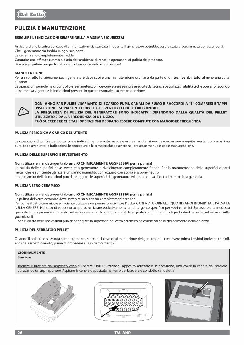
ITALIANO
PULIZIA E MANUTENZIONEESEGUIRE LE INDICAZIONI SEMPRE NELLA MASSIMA SICUREZZA!
Assicurarsi che la spina del cavo di alimentazione sia staccata in quanto il generatore potrebbe essere stata programmata per accendersi. Che il generatore sia freddo in ogni sua parte.Le ceneri siano completamente fredde.Garantire una e�cace ricambio d'aria dell’ambiente durante le operazioni di pulizia del prodotto.Una scarsa pulizia pregiudica il corretto funzionamento e la sicurezza!
MANUTENZIONEPer un corretto funzionamento, il generatore deve subire una manutenzione ordinaria da parte di un tecnico abilitato, almeno una volta all’anno.Le operazioni periodiche di controllo e le manutenzioni devono essere sempre eseguite da tecnici specializzati, abilitati che operano secondo la normativa vigente e le indicazioni presenti in questo manuale uso e manutenzione.
GIORNALMENTE Braciere:
Togliere il braciere dall’apposito vano e liberare i fori utilizzando l’apposito attizzatoio in dotazione, rimuovere la cenere dal braciere utilizzando un aspirapolvere. Aspirare la cenere depositata nel vano del braciere e condotto candeletta
OGNI ANNO FAR PULIRE L’IMPIANTO DI SCARICO FUMI, CANALI DA FUMO E RACCORDI A “T” COMPRESI E TAPPI D'ISPEZIONE - SE PRESENTI CURVE E GLI EVENTUALI TRATTI ORIZZONTALI!LA FREQUENZA DI PULIZIA DEL GENERATORE SONO INDICATIVI! DIPENDONO DALLA QUALITÀ DEL PELLET UTILIZZATO E DALLA FREQUENZA DI UTILIZZO. PUÒ SUCCEDERE CHE TALI OPERAZIONI DEBBANO ESSERE COMPIUTE CON MAGGIORE FREQUENZA.
PULIZIA PERIODICA A CARICO DEL UTENTE
Le operazioni di pulizia periodica, come indicato nel presente manuale uso e manutenzione, devono essere eseguite prestando la massima cura dopo aver letto le indicazioni, le procedure e le tempistiche descritte nel presente manuale uso e manutenzione.
PULIZIA DELLE SUPERFICI E RIVESTIMENTO
Non utilizzare mai detergenti abrasivi O CHIMICAMENTE AGGRESSIVI per la pulizia!La pulizia delle super�ci deve avvenire a generatore e rivestimento completamente freddo. Per la manutenzione delle super�ci e parti metalliche, e su�ciente utilizzare un panno inumidito con acqua o con acqua e sapone neutro.Il non rispetto delle indicazioni può danneggiare le super�ci del generatore ed essere causa di decadimento della garanzia.
PULIZIA VETRO CERAMICO
Non utilizzare mai detergenti abrasivi O CHIMICAMENTE AGGRESSIVI per la pulizia!La pulizia del vetro ceramico deve avvenire solo a vetro completamente freddo. Per pulire il vetro ceramico è su�ciente utilizzare un pennello asciutto e DELLA CARTA DI GIORNALE (QUOTIDIANO) INUMIDITA E PASSATA NELLA CENERE. Nel caso di vetro molto sporco utilizzare esclusivamente un detergente speci�co per vetri ceramici. Spruzzare una modesta quantità su un panno e utilizzarlo sul vetro ceramico. Non spruzzare il detergente o qualsiasi altro liquido direttamente sul vetro o sulle guarnizioni!Il non rispetto delle indicazioni può danneggiare la super�cie del vetro ceramico ed essere causa di decadimento della garanzia.
PULIZIA DEL SERBATOIO PELLET
Quando il serbatoio si svuota completamente, staccare il cavo di alimentazione del generatore e rimuovere prima i residui (polvere, trucioli, ecc.) dal serbatoio vuoto, prima di procedere al suo riempimento.
26

ITALIANO
Le immagini sono a scopo illustrativo
GIORNALMENTERaschiatori :
La pulizia degli scambiatori termici permette di garantire nel tempo una resa termica sempre costante. Questo tipo di manutenzione deve essere eseguita almeno una volta al giorno. Per fare questo è su�ciente utilizzare gli appositi raschiatori posti nella parte superiore della stufa, eseguendo il movimento dal basso verso l’alto e viceversa più volte.
SETTIMANALMENTE Pulizia Camera di combustione e cassetto cenere:
Settimanalmente o quando ce ne sia il bisogno, svuotare la cenere dal cassetto previsto. Si raccomanda almeno una volta alla settimana aspirare le ceneri nella camera di combustione con un aspirapolvere adeguato.
27

ITALIANO
MANUTENZIONE ORDINARIA ESEGUITA DAI TECNICI ABILITATI
La manutenzione ordinaria deve essere eseguita almeno una volta all'anno.Il generatore utilizzando pellet come combustibile solido necessità di un intervento annuale di manutenzione ordinaria che deve essere e�ettuate da un tecnico abilitato, utilizzando esclusivamente ricambi originali.Il mancato rispetto può compromettere la sicurezza dell’apparecchio e può far decadere il diritto alle condizioni di garanzia.Rispettando le frequenze di pulizie riservate all'utente descritte nel manuale uso e manutenzione, si garantisce al generatore una corretta combustione nel tempo, evitando eventuali anomalie e/o malfunzionamenti che potrebbero richiedere maggiori interventi del tecnico. Le richieste di interventi di manutenzione ordinaria non sono contemplate nella garanzia del prodotto.
GUARNIZIONI PORTA, CASSETTO CENERE E BRACIERE
Le guarnizioni garantiscono l’ermeticità della stufa e il conseguente buon funzionamento della stessa.E’ necessario che esse vengano periodicamente controllate: nel caso risultassero usurate o danneggiate è necessario sostituire immediatamente.Queste operazioni dovranno essere eseguite da parte di un tecnico abilitato.
COLLEGAMENTO AL CAMINO
Annualmente o comunque ogni volta che se ne presenti la necessità aspirare e pulire il condotto che porta al camino. Se esistono dei tratti orizzontali è necessario asportare i residui prima che questi ostruiscano il passaggio dei fumi.
MESSA FUORI SERVIZIO (FINE STAGIONE)
A �ne di ogni stagione, prima di spegnere la stufa, si consiglia di svuotare completamente il serbatoio del pellet, aspirando eventuali residui di pellet e polveri al suo interno.VI CONSIGLIAMO DI NON SCOLLEGARE IL GENERATORE DALLA RETE ELETTRICA, PER PERMETTERE AL CIRCOLATORE DI EFFETTUARE I NORMALI CICLI ANTIBLOCCAGGIO.La manutenzione ordinaria deve essere eseguita almeno una volta all'anno.
SE IL CAVO DI ALIMENTAZIONE È DANNEGGIATO, DEVE ESSERE SOSTITUITO DAL SERVIZIO DI ASSISTENZA TECNICA O COMUNQUE DA UNA PERSONA CON QUALIFICA SIMILARE, IN MODO DA PREVENIRE OGNI RISCHIO.
MENSILMENTE - JOLE IDRO 2.0
Rimuovere la cenere depositata nella parte alta della parete focolare (vedi �gura sotto)
28

B
E
D
C
A
C
F
D
EE
F
ITALIANO
MANUTENZIONE ORDINARIALe immagini sono a scopo illustrativo
A Motore fumi (smontaggio e pulizia e condotto fumi e "T"), nuovo silicone nei punti previsti
B Guarnizioni ispezioni, cassetto cenere e porta (sostituire e applicare silicone dove previsto)
C Camera di combustione & scambiatore (pulizia totale) compreso pulizia condotto candeletta
D Serbatoio (svuotamento completo e pulizia). E *Smontaggio ventilatore aria ambiente e
rimozione di polvere e detriti di pellet eventuali F Veri�ca tubo di aspirazione aria ed eventuale
pulizia del sensore di �usso
29
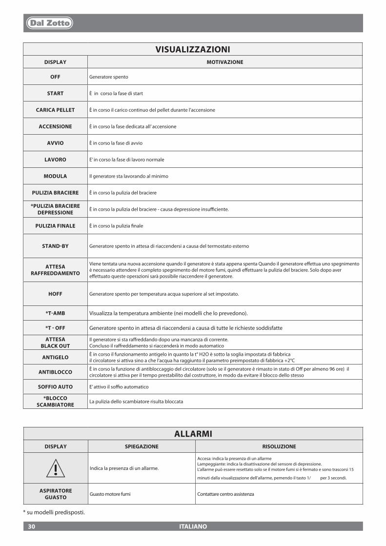
ITALIANO
VISUALIZZAZIONIDISPLAY MOTIVAZIONE
OFF Generatore spento
START È in corso la fase di start
CARICA PELLET È in corso il carico continuo del pellet durante l’accensione
ACCENSIONE È in corso la fase dedicata all’ accensione
AVVIO È in corso la fase di avvio
LAVORO E’ in corso la fase di lavoro normale
MODULA Il generatore sta lavorando al minimo
PULIZIA BRACIERE È in corso la pulizia del braciere
*PULIZIA BRACIEREDEPRESSIONE
È in corso la pulizia del braciere - causa depressione insu�ciente.
PULIZIA FINALE È in corso la pulizia �nale
STAND-BY Generatore spento in attesa di riaccendersi a causa del termostato esterno
ATTESA RAFFREDDAMENTO
Viene tentata una nuova accensione quando il generatore è stata appena spenta Quando il generatore e�ettua uno spegnimento è necessario attendere il completo spegnimento del motore fumi, quindi e�ettuare la pulizia del braciere. Solo dopo aver e�ettuato queste operazioni sarà possibile riaccendere il generatore.
HOFF Generatore spento per temperatura acqua superiore al set impostato.
*T-AMB Visualizza la temperatura ambiente (nei modelli che lo prevedono).
*T - OFF Generatore spento in attesa di riaccendersi a causa di tutte le richieste soddisfatte
ATTESA BLACK OUT
Il generatore si sta ra�reddando dopo una mancanza di corrente. Concluso il ra�reddamento si riaccenderà in modo automatico
ANTIGELO È in corso il funzionamento antigelo in quanto la t° H2O è sotto la soglia impostata di fabbricail circolatore si attiva sino a che l’acqua ha raggiunto il parametro preimpostato di fabbrica +2°C
ANTIBLOCCO È in corso la funzione di antibloccaggio del circolatore (solo se il generatore è rimasto in stato di O� per almeno 96 ore) il circolatore si attiva per il tempo prestabilito dal costruttore, in modo da evitare il blocco dello stesso
SOFFIO AUTO E’ attivo il so�o automatico
*BLOCCO SCAMBIATORE
La pulizia dello scambiatore risulta bloccata
ALLARMIDISPLAY SPIEGAZIONE RISOLUZIONE
Indica la presenza di un allarme.
Accesa: indica la presenza di un allarmeLampeggiante: indica la disattivazione del sensore di depressione.L’allarme può essere resettato solo se il motore fumi si è fermato e sono trascorsi 15
minuti dalla visualizzazione dell’allarme, pemendo il tasto 1/ per 3 secondi.
ASPIRATORE GUASTO
Guasto motore fumi Contattare centro assistenza
* su modelli predisposti.
30
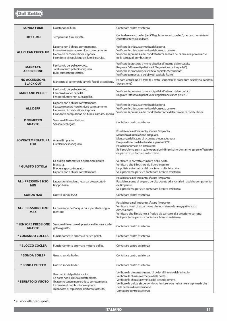
ITALIANO
* su modelli predisposti.
SONDA FUMI Guasto sonda fumi. Contattare centro assistenza
HOT FUMI Temperatura fumi elevata Controllare carico pellet (vedi “Regolazione carico pellet”), nel caso non si risolvi contattare tecnico abilitato.
ALL CLEAN CHECH UP
La porta non è chiusa correttamente.Il cassetto cenere non è chiuso correttamente.La camera di combustione è sporca.Il condotto di espulsione dei fumi è ostruito.
Veri�care la chiusura ermetica della porta.Veri�care la chiusura ermetica del cassetto cenere.Veri�care la pulizia sia del condotto fumi, sensore nel canale aria primaria che della camera di combustione.
MANCATA ACCENSIONE
Il serbatoio del pellet è vuoto.Taratura carico pellet inadeguata.Bulbi termostatici scattati.
Veri�care la presenza o meno di pellet all’interno del serbatoio.Regolare l’a�usso di pellet (vedi “Regolazione carico pellet”).Veri�care le procedure descritte al capitolo “Accensione”.Veri�care termostati a bulbi (vedi capitolo Riarmi)
NO ACCENSIONE BLACK OUT
Mancanza di corrente durante la fase di accensione. Portare la stufa in OFF tramite il tasto 1 e ripetere le procedure descritte al capitolo “Accensione”.
MANCANO PELLET Il serbatoio del pellet è vuoto.Carenza di carico di pellet.Il motoriduttore non carica pellet.
Veri�care la presenza o meno di pellet all’interno del serbatoio.Regolare l’a�usso di pellet(vedi “Regolazione carico pellet”).
ALL DEPR
La porta non è chiusa correttamente.Il cassetto cenere non è chiuso correttamente.La camera di combustione è sporca.Il condotto di espulsione dei fumi è ostruito/ sporco
Veri�care la chiusura ermetica della porta.Veri�care la chiusura ermetica del cassetto cenere.Veri�care la pulizia sia del condotto fumi che della camera di combustione.
DEBIMETRO GUASTO
Sensore di �usso difettoso.Sensore scollegato Contattare centro assistenza
SOVRATEMPERATURA H20
Aria nell’impiantoCircolazione inadeguata
Possibile aria nell’impianto, s�atare l'impianto.Mancanza di circolazione adeguata,.Mancanza della zona di sicurezza o non adeguata.L'acqua all’interno della stufa ha superato i 95°C. Possibile anomalia del circolatore.Se il problema persiste, le operazioni di ripristino dovranno essere e�ettuate da parte di un tecnico autorizzato.
* GUASTO BOTOLA
La pulizia automatica del braciere risulta bloccata. Braciere sporco intasatoLa porta non è chiusa correttamente.
Veri�care la corretta chiusura della porta.Veri�care che il braciere sia libero e pulito.La pulizia automatica del braciere risulta bloccata.Se il problema persiste contattare il centro assistenza
ALL-PRESSIONE H2O MIN
La pressione impianto letta dal pressostato è troppo bassa.
Possibile aria nell’impianto, s�atare l'impianto.Possibile carenza di acqua o perdite dovute ad anomalie in qualche componente dell’impianto.Se il problema persiste contattare il centro assistenza
SONDA H2O Guasto sonda H2O Contattare centro assistenza
ALL-PRESSIONE H2O MAX
La pressione dell’ acqua ha superato la soglia massima
Possibile aria nell’impianto, s�atare l'impianto.Veri�care i vasi di espansione che non siano danneggiati o sotto dimensionatiVeri�care che l’impianto a freddo sia caricato alla pressione correttaSe il problema persiste contattare il centro assistenza
* SENSORE PRESSIONE GUASTO
Sensore di�erenziale di pressione difettoso, scolle-gato o guasto.
Contattare centro assistenza
* COMANDO COCLEA Funzionamento anomalo carico pellet. Contattare centro assistenza
* BLOCCO COCLEA Funzionamento anomalo motore pellet. Contattare centro assistenza
* SONDA BOILER Guasto sonda boiler. Contattare centro assistenza
* SONDA PUFFER Guasto sonda boiler. Contattare centro assistenza
* SERBATOIO VUOTO
Il serbatoio del pellet è vuoto. La porta non è chiusa correttamente.Il cassetto cenere non è chiuso correttamente.La camera di combustione è sporca.Il condotto di espulsione dei fumi è ostruito.
Veri�care la presenza o meno di pellet all’interno del serbatoio.Veri�care la chiusura ermetica della porta.Veri�care la chiusura ermetica del cassetto cenere.Veri�care la pulizia sia del condotto fumi, sensore nel canale aria primaria che della camera di combustione.Contattare centro assistenza
31
ITALIANO
1. I prodotti DAL ZOTTO marchio commerciale di La Nordica S.p.A. sono garantiti, nell’ambito della comunità europea, per un periodo di 24 mesi dalla data di acquisto. L’acquisto deve essere provato da un documento �scalmente valido rilasciato dal rivenditore (scontrino �scale, fattura o bolla di trasporto) che identi�chi il prodotto acquistato e la data di acquisto e/o consegna dello stesso.
ATTENZIONE: La presente garanzia convenzionale non sostituisce la garanzia prevista dalle norme europee a tutela dei Consumatori.
La garanzia convenzionale si deve intendere limitata al territorio Italiano ed a quei territori all’interno della Comunità Europea coperti dal servizio di centri di assistenza tecnica autorizzati (veri�care sul sito www.dalzotto.com)Deve inoltre intendersi delimitata territorialmente allo stato di residenza e/o domicilio del consumatore che deve essere lo stesso ove ha la sede legale e/o d’a�ari il venditore del prodotto DAL ZOTTO.Le presenti norme non si applicano nei casi di acquisto del prodotto nell’ambito di attività commerciali, imprenditoriali o professionali. In questi casi la garanzia del prodotto sarà limitata ad un periodo di 12 mesi dalla data di acquisto.
GARANZIA ITALIACosa fare in caso di anomalia nel funzionamento del prodotto: Consultare il libretto di istruzioni per accertarsi che l’anomalia non possa essere risolta con la corretta applicazione delle funzionalità del prodotto stesso. Accertarsi che il difetto rientri nella tipologia di anomalie coperte da garanzia; in caso contrario il costo dell’intervento sarà a completo carico del consumatore. Quando richiedete l’intervento del Servizio Assistenza al Centro di Assistenza Autorizzato indicate sempre: - natura del difetto - modello del vostro apparecchio - indirizzo completo - numero di telefono
GARANZIA EUROPACosa fare in caso di anomalia nel funzionamento del prodotto: Consultare il libretto di istruzioni per accertarsi che l’anomalia non possa essere risolta con la corretta applicazione delle funzionalità del prodotto stesso. Accertarsi che il difetto rientri nella tipologia di anomalie coperte da garanzia; in caso contrario il costo dell’intervento sarà a completo carico del consumatore. Richiedete l’intervento del Servizio Assistenza o l’indirizzo del centro di assistenza tecnica autorizzato al venditore indicando sempre: natura del difetto, modello del vostro apparecchio, indirizzo completo e numero di telefono
Per il difetto di conformità manifestatosi nei primi 6 mesi di vita del prodotto il consumatore ha diritto alla riparazione del difetto senza alcuna spesa. Dal settimo al ventiquattresimo mese, nel caso in cui sia stato accertato un vizio di conformità, il consumatore dovrà sostenere il costo della chiamata mentre il venditore continuerà a farsi carico del costo della manodopera e di eventuali ricambi funzionali utilizzati.
2. Qualora il difetto riscontrato sia riconducibile a condizioni e/o eventi esterni quali, a puro titolo esempli�cativo e non esaustivo, portata insu�ciente degli impianti; errata installazione e/o manutenzione operata da personale non in possesso dei requisiti previsti dalle leggi in vigore nel paese di residenza del consumatore; negligenza; incapacità d’uso e cattiva manutenzione da parte del consumatore, rispetto a quanto riportato e raccomandato nel libretto di istruzioni del prodotto, che costituisce parte integrante del contratto di vendita, decade la presente garanzia. Non sono altresì compresi nella presente garanzia i danni subiti dal prodotto in assenza di cause provate imputabili a vizi di fabbricazione. Allo stesso modo sono esclusi dalla presente garanzia i vizi riconducibili al mancato corretto funzionamento della canna fumaria, ai sensi della legislazione in vigore nel paese al momento dell’acquisto, così come tutti i difetti del prodotto dovuti ad incuria, rottura accidentale, manomissione e/o danneggiamento nel trasporto (gra�, ammaccature etc.), interventi eseguiti da personale non autorizzato ed ulteriori danni causati da erronei interventi del consumatore nel tentativo di porre rimedio all’iniziale guasto. Sono esclusi da garanzia i seguenti materiali di consumo: le guarnizioni, i vetri ceramici o temperati, i rivestimenti e griglie in ghisa, materiali refrattari ( es. Nordiker o altro), i particolari verniciati, cromati o dorati, gli elementi in maiolica, le maniglie, il braciere ed i relativi componenti. Nei prodotti Idro lo scambiatore di calore è escluso dalla garanzia nel caso in cui non venga realizzato un adeguato circuito anticondensa che garantisca una temperatura di ritorno dell’apparecchio di almeno 55 gradi. In generale sono esclusi da garanzia tutti i componenti esterni al prodotto sui quali il consumatore può intervenire direttamente durante l’uso e/o manutenzione o che possono essere soggetti ad usura, e/o la formazione di ruggine, macchie su acciaio dovute all’utilizzo di detergenti aggressivi. In caso di segnalazione di difetti non riscontrati poi in fase di veri�ca da parte di un tecnico autorizzato, l’intervento sarà a completo carico del consumatore.
3. Qualora il ripristino alla conformità non fosse possibile attraverso la riparazione del prodotto/componente, si provvederà alla sostituzione, lasciando immutati la scadenza ed i termini di garanzia acquisiti al momento dell’acquisto del prodotto/componente da sostituire.
4. La DAL ZOTTO marchio commerciale di La Nordica S.p.A. declina ogni responsabilità per eventuali danni che possono, direttamente o indirettamente, derivare a persone, animali e cose, in conseguenza alla mancata osservanza di tutte le prescrizioni indicate nell’apposito libretto istruzioni e concernenti le avvertenze in tema di installazione, uso e manutenzione del prodotto, scaricabile anche dal sito internet.
5. Sono esclusi dalla garanzia gli interventi per la taratura e/o regolazione del prodotto in relazione al tipo di combustibile o altro.
CONDIZIONI DI GARANZIA
32
ITALIANO
6. Qualora il Prodotto venisse riparato presso uno dei Centri Assistenza Tecnica Autorizzati indicati dalla DAL ZOTTO e nel caso di sostituzione del prodotto, il trasporto sarà gratuito. Nei casi in cui il tecnico fosse in grado di riparare il prodotto presso il domicilio dell’utente, è lo stesso si ri�utasse, il trasporto in laboratorio e la riconsegna saranno invece a suo carico.
7. Trascorso il periodo di 24 mesi di garanzia ogni intervento di riparazione sarà a completo carico del consumatore.
8. In caso di controversie il foro giudiziario esclusivamente competente è il foro della sede legale di DAL ZOTTO -(Vicenza-Italia)
ULTERIORI AVVERTENZE
� Utilizzare esclusivamente il combustibile raccomandato dal produttore. Il prodotto non deve essere utilizzato come inceneritore. � Non utilizzare il prodotto come scala o struttura di appoggio. � Non mettere ad asciugare biancheria sul prodotto. Eventuali stendibiancheria o simili devono essere tenuti ad apposita distanza dal
prodotto. Pericolo di incendio e danneggiamento del rivestimento. � Ogni responsabilità per un uso improprio del prodotto è totalmente a carico dell’utente e solleva il produttore da ogni responsabilità
civile e penale. � Qualsiasi tipo di manomissione o di sostituzione non autorizzata di particolari non originali del prodotto può essere pericoloso per
l’incolumità dell’operatore e sollevano la ditta da ogni responsabilità civile e penale. � Gran parte delle super�ci del prodotto sono molto calde (porta, maniglia, vetro, tubi uscita fumi, ecc.). Occorre quindi evitare di entrare
in contatto con queste parti senza adeguati indumenti di protezione o appositi mezzi, come ad esempio guanti a protezione termica � E’ vietato far funzionare il prodotto con la porta aperta o con il vetro rotto. � Il prodotto deve essere connesso elettricamente ad un impianto munito di un e�cace sistema di messa a terra. � Spegnere il prodotto in caso di guasto o cattivo funzionamento. � L’accumulo di pellet incombusto nel bruciatore dopo ogni “mancata accensione” deve essere rimosso prima di procedere con una nuova
accensione. Controllare che il bruciatore sia pulito e ben posizionato prima di riaccendere. � Non lavare il prodotto con acqua. L’acqua potrebbe penetrare all’interno dell’unità e guastare gli isolamenti elettrici, provocando scosse
elettriche. � Le installazioni non rispondenti alle norme vigenti fanno decadere la garanzia del prodotto, così come l’uso improprio e la mancata
manutenzione come prevista dal costruttore.
33
ENGLISH
WARNINGS
This instructions manual is an integral part of the product: make sure that it always accompanies the appliance, even if transferred to another owner or user, or if transferred to another place. If it is damaged or lost, request another copy from the area technician. This product is intended for the use for which it has been expressly designed. The manufacturer is exempt from any liability, contractual and extracon-tractual, for injury/damage caused to persons/animals and objects, due to installation, adjustment and maintenance errors and improper use.Installation must be performed by quali�ed sta�, which assumes complete responsibility for the de-�nitive installation and consequent good functioning of the product installed. One must also bear in mind all laws and national, regional, provincial and town council Standards present in the country in which the appliance has been installed, as well as the instructions contained in this manual.The Manufacturer cannot be held responsible for the failure to comply with such precautions.After removing the packaging, ensure that the content is intact and complete. Otherwise, contact the dealer where the appliance was purchased.All electric components that make up the product must be replaced with original spare parts exclusively by an authorised after-sales centre, thus guaranteeing correct functioning.
SAFETY
� THE APPLIANCE MAY BE USED BY CHILDREN 8 YEARS OF AGE OR OLDER AND INDIVIDUALS WITH REDUCED PHYSICAL, SENSORY, OR MENTAL CAPACITIES OR WITHOUT EXPERIENCE OR THE NECESSARY KNOWLEDGE, PROVIDED THAT THEY ARE SUPERVISED OR HAVE RECEIVED INSTRUCTIONS ON SAFE USE OF THE APPLIANCE AND THAT THEY UNDERSTAND THE INHERENT DANGERS.
� THE GENERATOR MUST NOT BE USED BY PERSONS (INCLUDING CHILDREN) WITH REDUCED PHYSICAL, SENSORY AND MENTAL CAPACITIES OR WHO ARE UNSKILLED PERSONS, UNLESS THEY ARE SUPERVISED AND TRAINED REGARDING USE OF THE APPLIANCE BY A PERSON RESPONSIBLE FOR THEIR SAFETY.
� THE CLEANING AND MAINTENANCE REQUIRED BY THE USER MUST NOT BE PERFORMED BY CHILDREN WITHOUT SUPERVISION.
� CHILDREN MUST BE CHECKED TO ENSURE THAT THEY DO NOT PLAY WITH THE APPLIANCE. � DO NOT TOUCH THE GENERATOR WHEN YOU ARE BAREFOOT OR WHEN PARTS OF THE BODY
ARE WET OR DAMP. � THE SAFETY AND ADJUSTMENT DEVICES MUST NOT BE MODIFIED WITHOUT THE AUTHORISATION
OR INDICATIONS OF THE MANUFACTURER. � DO NOT PULL, REMOVE, TWIST THE ELECTRICAL CABLES COMING OUT OF THE PRODUCT EVEN
IF IT IS DISCONNECTED FROM THE MAINS. � IT IS ADVISED TO POSITION THE POWER SUPPLY CABLE SO THAT IT DOES NOT COME INTO
CONTACT WITH HOT PARTS OF THE APPLIANCE. � THE POWER SUPPLY PLUG MUST BE ACCESSIBLE AFTER INSTALLATION. � DO NOT CLOSE OR REDUCE THE DIMENSIONS OF THE AIRING VENTS IN THE PLACE OF
INSTALLATION. THE AIRING VENTS ARE ESSENTIAL FOR CORRECT COMBUSTION. � DO NOT LEAVE THE PACKAGING ELEMENTS WITHIN REACH OF CHILDREN OR UNASSISTED
We thank you for having chosen our company; our product is a great heating solution developed from the most advanced technology with top quality machining and modern design, aimed at making you enjoy the fantastic sensation that the heat of a �ame gives, in complete safety.
34
ENGLISH
DISABLED PERSONS. � THE HEARTH DOOR MUST ALWAYS BE CLOSED DURING NORMAL FUNCTIONING OF THE
PRODUCT. � WHEN THE APPLIANCE IS FUNCTIONING AND HOT TO THE TOUCH, ESPECIALLY ALL EXTERNAL
SURFACES, ATTENTION MUST BE PAID � CHECK FOR THE PRESENCE OF ANY OBSTRUCTIONS BEFORE SWITCHING THE APPLIANCE ON
FOLLOWING A PROLONGED PERIOD OF INACTIVITY. � THE GENERATOR HAS BEEN DESIGNED TO FUNCTION IN ANY CLIMATIC CONDITION. IN
PARTICULARLY ADVERSE CONDITIONS (STRONG WIND, FREEZING) SAFETY SYSTEMS MAY INTERVENE THAT SWITCH THE GENERATOR OFF. IF THIS OCCURS, CONTACT THE TECHNICAL AFTER-SALES SERVICE AND ALWAYS DISABLE THE SAFETY SYSTEMS.
� IN THE EVENT THE FLUE CATCHES FIRE, USE SUITABLE SYSTEMS FOR SUFFOCATING THE FLAMES OR REQUEST HELP FROM THE FIRE BRIGADE.
� THIS APPLIANCE MUST NOT BE USED TO BURN WASTE � DO NOT USE ANY FLAMMABLE LIQUIDS FOR IGNITION � DURING THE FILLING PHASE DO NOT PUT THE BAG OF PELLETS TO INTO CONTACT WITH THE
PRODUCT � THE MAJOLICAS ARE TOP QUALITY ARTISAN PRODUCTS AND AS SUCH CAN HAVE MICRO-DOTS,
CRACKLES AND CHROMATIC IMPERFECTIONS. THESE FEATURES HIGHLIGHT THEIR VALUABLE NATURE. DUE TO THEIR DIFFERENT DILATION COEFFICIENT, THEY PRODUCE CRACKLING, WHICH DEMONSTRATE THEIR EFFECTIVE AUTHENTICITY. TO CLEAN THE MAJOLICAS, IT IS RECOMMENDED TO USE A SOFT, DRY CLOTH. IF A DETERGENT OR LIQUID IS USED, THE LATTER COULD PENETRATE INSIDE THE CRACKLES, HIGHLIGHTING THEM.
ROUTINE MAINTENANCE
Based on Decree 22 January 2008 n°37 art.2, routine maintenance means interventions aimed at redu-cing degradation due to normal use, as well as dealing with accidental events entailing the need of �rst interventions, which however do not modify the structure of the system upon which one is intervening or its intended use according to the requirements laid down by the technical standards in force and by the manufacturer's use and maintenance manual.
35
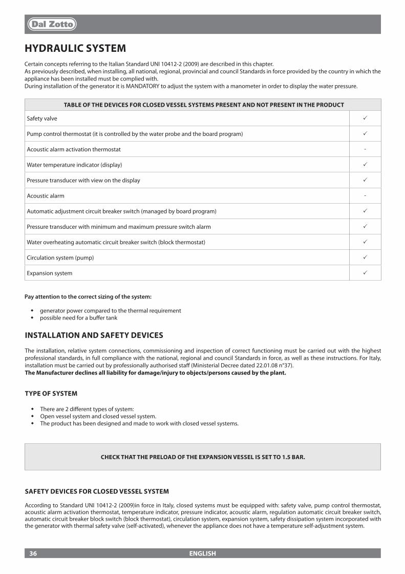
ENGLISH
HYDRAULIC SYSTEMCertain concepts referring to the Italian Standard UNI 10412-2 (2009) are described in this chapter. As previously described, when installing, all national, regional, provincial and council Standards in force provided by the country in which the appliance has been installed must be complied with.During installation of the generator it is MANDATORY to adjust the system with a manometer in order to display the water pressure.
TABLE OF THE DEVICES FOR CLOSED VESSEL SYSTEMS PRESENT AND NOT PRESENT IN THE PRODUCT
Safety valve p
Pump control thermostat (it is controlled by the water probe and the board program) p
Acoustic alarm activation thermostat -
Water temperature indicator (display) p
Pressure transducer with view on the display p
Acoustic alarm -
Automatic adjustment circuit breaker switch (managed by board program) p
Pressure transducer with minimum and maximum pressure switch alarm p
Water overheating automatic circuit breaker switch (block thermostat) p
Circulation system (pump) p
Expansion system p
INSTALLATION AND SAFETY DEVICES
The installation, relative system connections, commissioning and inspection of correct functioning must be carried out with the highest professional standards, in full compliance with the national, regional and council Standards in force, as well as these instructions. For Italy, installation must be carried out by professionally authorised sta� (Ministerial Decree dated 22.01.08 n°37).The Manufacturer declines all liability for damage/injury to objects/persons caused by the plant.
TYPE OF SYSTEM
� There are 2 di�erent types of system: � Open vessel system and closed vessel system. � The product has been designed and made to work with closed vessel systems.
CHECK THAT THE PRELOAD OF THE EXPANSION VESSEL IS SET TO 1.5 BAR.
SAFETY DEVICES FOR CLOSED VESSEL SYSTEM
According to Standard UNI 10412-2 (2009)in force in Italy, closed systems must be equipped with: safety valve, pump control thermostat, acoustic alarm activation thermostat, temperature indicator, pressure indicator, acoustic alarm, regulation automatic circuit breaker switch, automatic circuit breaker block switch (block thermostat), circulation system, expansion system, safety dissipation system incorporated with the generator with thermal safety valve (self-activated), whenever the appliance does not have a temperature self-adjustment system.
Pay attention to the correct sizing of the system:
� generator power compared to the thermal requirement � possible need for a bu�er tank
36
ENGLISH
DISTANCES OF SAFETY DEVICES ACCORDING TO THE STANDARD
The temperature safety sensors must be in place on the machine at a distance no greater than 30 cm from the �ow connection. Whenever the generators lack a device, those missing can be installed on the generator �ow pipe, within a distance no greater than 1 m from the machine.
COMMISSIONING CHECKS
Before connecting the boiler:a) wash all system piping thoroughly in order to remove any residues which might compromise the correct functioning of certain system components (pumps, valves, etc.).b) The company highly recommends installing a magnetic �lter in the generator return to increase the life of the boiler, facilitate removal of impurities, and increase the overall e�ciency of the system.c) check to verify that the �ue has adequate draught, that it is not narrowed and that other appliances do not discharge into the �ue. This is to prevent unexpected power increases. The �ue �tting can be mounted between the boiler and the �ue only after this inspection. An inspection of the connections with pre-existing �ues is recommended.
ANTI-CONDENSATION DEVICE (MANDATORY)Make sure a suitable anti-condensate circuit has been realised, which guarantees an appliance return temperature of at least 55°C. The automatic thermostatic valve, for instance, is used in solid fuel boilers as it prevents cold water from returning into the exchanger. A high return temperature allows e�ciency improvement, reduces formation of smoke condensation and prolongs the generator’s life span. The manufacturer recommends using the 55°C model with 1” hydraulic connections.For the products with the PWM pump control thermostat, installation is considered equivalent to the realisation of a suitable anti-condensate circuit in the case where::
- the heat generator pump is the only one in the installation, or- there is a plate heat exchanger between the heat generator and the installation, or- there is a hydraulic compensator or an inertial storage tank (bu�er) between the heat generator and the installation
Valve on sale as an accessory (optional)
37
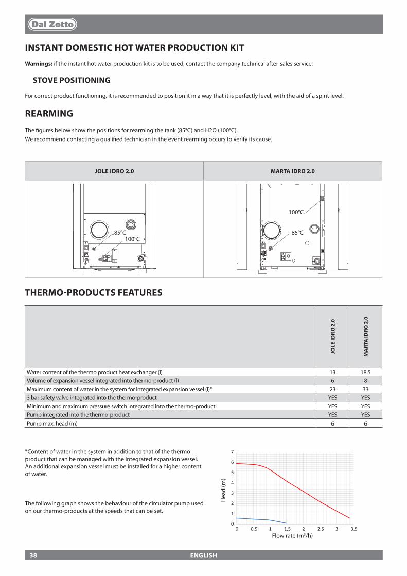
0
1
2
3
4
5
6
7
0 0,5 1 1,5 2 2,5 3 3,5
JOLE IDRO 2.0 MARTA IDRO 2.0
85°C 100°C
85°C 85°C
100°C
100°C
85°C 100°C
85°C 85°C
100°C
100°C
ENGLISH
INSTANT DOMESTIC HOT WATER PRODUCTION KITWarnings: if the instant hot water production kit is to be used, contact the company technical after-sales service.
STOVE POSITIONING
For correct product functioning, it is recommended to position it in a way that it is perfectly level, with the aid of a spirit level.
REARMING
The �gures below show the positions for rearming the tank (85°C) and H2O (100°C).We recommend contacting a quali�ed technician in the event rearming occurs to verify its cause.
*Content of water in the system in addition to that of the thermo product that can be managed with the integrated expansion vessel. An additional expansion vessel must be installed for a higher content of water.
The following graph shows the behaviour of the circulator pump used on our thermo-products at the speeds that can be set.
Flow rate (m3/h)
Hea
d (m
)
THERMO-PRODUCTS FEATURES
JOLE
IDRO
2.0
MA
RTA
IDRO
2.0
Water content of the thermo product heat exchanger (l) 13 18.5Volume of expansion vessel integrated into thermo-product (l) 6 8Maximum content of water in the system for integrated expansion vessel (l)* 23 333 bar safety valve integrated into the thermo-product YES YESMinimum and maximum pressure switch integrated into the thermo-product YES YESPump integrated into the thermo-product YES YESPump max. head (m) 6 6
38
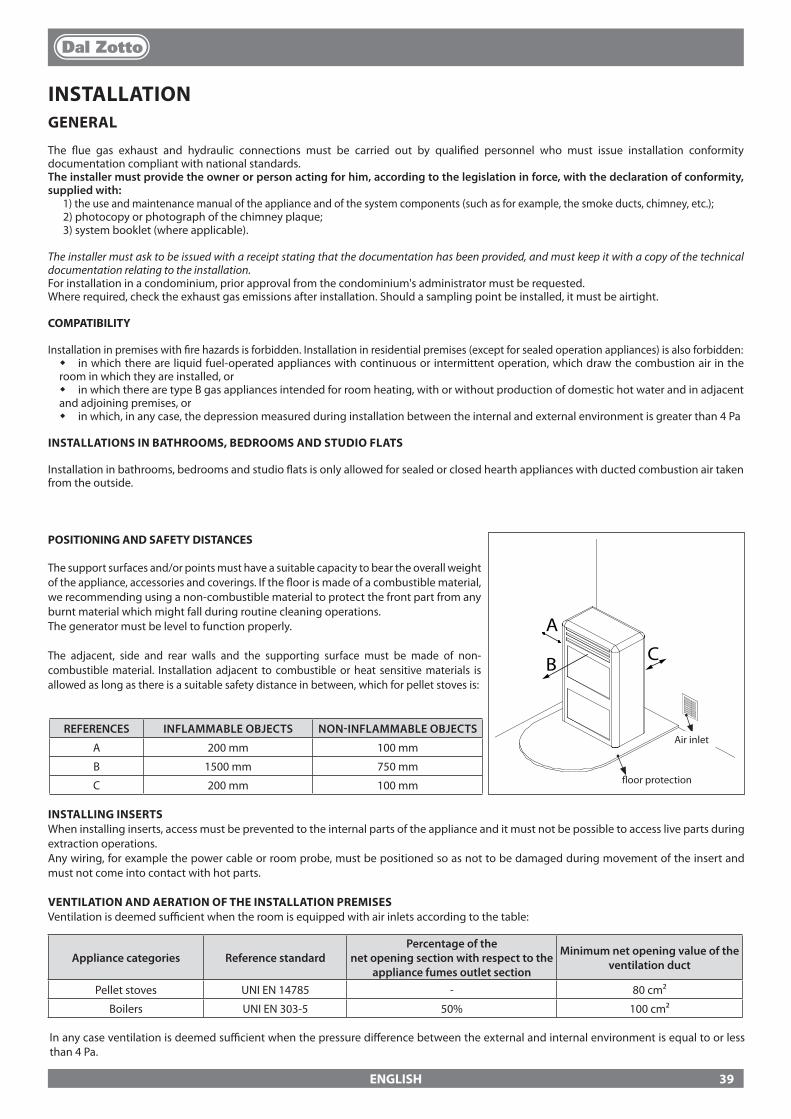
A
CB
ENGLISH
Air inletREFERENCES INFLAMMABLE OBJECTS NON-INFLAMMABLE OBJECTS
A 200 mm 100 mm
B 1500 mm 750 mm
C 200 mm 100 mm �oor protection
INSTALLING INSERTSWhen installing inserts, access must be prevented to the internal parts of the appliance and it must not be possible to access live parts during extraction operations.Any wiring, for example the power cable or room probe, must be positioned so as not to be damaged during movement of the insert and must not come into contact with hot parts.
VENTILATION AND AERATION OF THE INSTALLATION PREMISESVentilation is deemed su�cient when the room is equipped with air inlets according to the table:
Appliance categories Reference standardPercentage of the
net opening section with respect to the appliance fumes outlet section
Minimum net opening value of the ventilation duct
Pellet stoves UNI EN 14785 - 80 cm²
Boilers UNI EN 303-5 50% 100 cm²
In any case ventilation is deemed su�cient when the pressure di�erence between the external and internal environment is equal to or less than 4 Pa.
INSTALLATIONGENERAL
The �ue gas exhaust and hydraulic connections must be carried out by quali�ed personnel who must issue installation conformity documentation compliant with national standards.The installer must provide the owner or person acting for him, according to the legislation in force, with the declaration of conformity, supplied with:
1) the use and maintenance manual of the appliance and of the system components (such as for example, the smoke ducts, chimney, etc.);2) photocopy or photograph of the chimney plaque;3) system booklet (where applicable).
The installer must ask to be issued with a receipt stating that the documentation has been provided, and must keep it with a copy of the technical documentation relating to the installation.For installation in a condominium, prior approval from the condominium's administrator must be requested.Where required, check the exhaust gas emissions after installation. Should a sampling point be installed, it must be airtight.
COMPATIBILITY
Installation in premises with �re hazards is forbidden. Installation in residential premises (except for sealed operation appliances) is also forbidden: � in which there are liquid fuel-operated appliances with continuous or intermittent operation, which draw the combustion air in the
room in which they are installed, or � in which there are type B gas appliances intended for room heating, with or without production of domestic hot water and in adjacent
and adjoining premises, or � in which, in any case, the depression measured during installation between the internal and external environment is greater than 4 Pa
INSTALLATIONS IN BATHROOMS, BEDROOMS AND STUDIO FLATS
Installation in bathrooms, bedrooms and studio �ats is only allowed for sealed or closed hearth appliances with ducted combustion air taken from the outside.
POSITIONING AND SAFETY DISTANCES
The support surfaces and/or points must have a suitable capacity to bear the overall weight of the appliance, accessories and coverings. If the �oor is made of a combustible material, we recommending using a non-combustible material to protect the front part from any burnt material which might fall during routine cleaning operations.The generator must be level to function properly.
The adjacent, side and rear walls and the supporting surface must be made of non-combustible material. Installation adjacent to combustible or heat sensitive materials is allowed as long as there is a suitable safety distance in between, which for pellet stoves is:
39
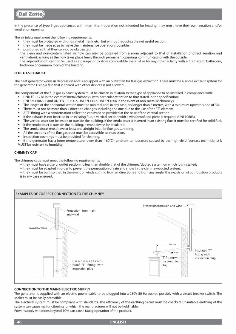
3 - 5%
Max 3 mt
ENGLISH
EXAMPLES OF CORRECT CONNECTION TO THE CHIMNEY
In the presence of type B gas appliances with intermittent operation not intended for heating, they must have their own aeration and/or ventilation opening.
The air inlets must meet the following requirements: � they must be protected with grids, metal mesh, etc., but without reducing the net useful section; � they must be made so as to make the maintenance operations possible; � positioned so that they cannot be obstructed;The clean and non-contaminated air �ow can also be obtained from a room adjacent to that of installation (indirect aeration and ventilation), as long as the �ow takes place freely through permanent openings communicating with the outside.The adjacent room cannot be used as a garage, or to store combustible material or for any other activity with a �re hazard, bathroom, bedroom or common room of the building.
FLUE GAS EXHAUST
The heat generator works in depression and is equipped with an outlet fan for �ue gas extraction. There must be a single exhaust system for the generator. Using a �ue that is shared with other devices is not allowed.
The components of the �ue gas exhaust system must be chosen in relation to the type of appliance to be installed in compliance with: � UNI/ TS 11278 in the event of metal chimneys, with particular attention to that stated in the speci�cation; � UNI EN 13063-1 and UNI EN 13063-2, UNI EN 1457, UNI EN 1806 in the event of non-metallic chimneys. � The length of the horizontal section must be minimal and, in any case, no longer than 3 metres, with a minimum upward slope of 3% � There must not be more than 4 direction changes including the one due to the use of the "T" element. � A “T” �tting with a condensation collection cap must be provided at the base of the vertical section. � If the exhaust is not inserted in an existing �ue, a vertical section with a windproof end piece is required (UNI 10683). � The vertical duct can be inside or outside the building. If the smoke duct is inserted in an existing �ue, it must be certi�ed for solid fuel. � If the smoke duct is outside the building, it must always be insulated. � The smoke ducts must have at least one airtight inlet for �ue gas sampling. � All the sections of the �ue gas duct must be accessible to inspection. � Inspection openings must be provided for cleaning. � If the generator has a fume temperature lower than 160°C+ ambient temperature caused by the high yield (contact technicians) it
MUST be resistant to humidity.
CHIMNEY CAP
The chimney caps must meet the following requirements: � they must have a useful outlet section no less than double that of the chimney/ducted system on which it is installed; � they must be adapted in order to prevent the penetration of rain and snow in the chimney/ducted system; � they must be built so that, in the event of winds coming from all directions and from any angle, the expulsion of combustion products
is in any case ensured;
Protection from rain and wind
C o n d e n s a t i o n -proof "T" �tting with inspection plug
Insulated �ue
Insulated "T" �tting with inspection plug
Protection from rain and wind
"T" �tting with i n s p e c t i o n plug
CONNECTION TO THE MAINS ELECTRIC SUPPLYThe generator is supplied with an electric power cable to be plugged into a 230V 50 Hz socket, possibly with a circuit breaker switch. The socket must be easily accessible.The electrical system must be compliant with standards. The e�ciency of the earthing circuit must be checked. Unsuitable earthing of the system can cause malfunctioning for which the manufacturer will not be held liable. Power supply variations beyond 10% can cause faulty operation of the product.
40

ENGLISH
PELLETS AND FEEDINGPellets are made by applying high pressure to sawdust, or wood waste products (not containing paint) from sawmills, carpentry and other activities related to processing and working with wood.
Given that it does not use any glue to hold it together this type of fuel is completely environmentally friendly. In fact the compactness of the pellets over time is guaranteed by a natural substance found in the wood itself: wood coal. In addition to being an environmentally friendly fuel in that it pushes wood residues to the limits pellets also have technical advantages. While wood has a calori�c value of 4.4kWh/kg. (with 15% humidity after around 18 months of seasoning) the calori�c value of pellets is 5 kWh/kg. Pellet density is 650kg/m3 and the water content is equal to 8% of its weight. For this reason they do not require seasoning in order to arrive at a su�ciently adequate degree of heat yield.
THE USE OF EXPIRED PELLETS OR ANY OTHER MATERIAL WILL AFFECT THE FUNCTIONALITY OF YOUR GENERATOR AND MAY LEAD TO THE TERMINATION OF THE WARRANTY AND CESSATION OF ANY ACCOMPANYING RESPONSIBILITY ON THE PART OF THE MANUFACTURER
The pellets used must comply with the characteristics described by the following standards:
� EN PLUS - UNI EN 14961 - 2 (UNI EN ISO 17225-2) class A1 or A2
The manufacturer always recommended using pellets with a diameter of 6 mm with its products.
PELLET STORAGE
In order to ensure problem-free combustion pellets must be stored in a dry place. Open the tank lid and load the pellets using a scoop.
CHECKS AND PRECAUTIONS FOR FIRST IGNITION
IMPORTANT!IN ORDER FOR THE GENERATOR TO WORK PROPERLY, THE HYDRAULIC SYSTEM’S PRESSURE MUST BE BETWEEN 0.6 AND 2.5 BAR.
If the pressure detected by the digital pressure switch is below 0.6 or above 2.5 bar, it triggers a boiler alarm. Bringing the water pressure within the standard values, it is possible to reset the alarm by pressing the button /1 for 3 seconds(The alarm can be reset only if the fumes motor has stopped and 15 minutes have elapsed from the display of the alarm)
THE PELLET LOADING MOTOR DOES NOT WORK:
Due to the �lling of the system, it is normal that there is air inside the circuit.During the 1st ignition cycle, water movement causes the displacement of air bubbles and their out-�ow from the automatic vents out of the system. This can cause the pressure to drop and activate the minimum pressure switch, which stops the motor that transports the pellets and, therefore, the heat generator.
Vent out the system, if necessary even multiple times, to remove the air, and reload it if the pressure is too low.It is not a malfunction, but a normal occurrence due to its �lling. After �lling, the plumber must always thoroughly vent the system, using the special vents in the circuit and running the "air breather" function on the machine. (After the �rst ignition and with a cold machine, re-activate the function "air breather" - see chapter "OTHER FUNCTIONS”)
BULB THERMOSTATS - RESET:
Check by pressing the reset buttons (85 - 100°C) located on the back of the appliance, before contacting a technician (see section RESET).
41

12
3
4
5
6
OFF
ENGLISH
CONTROL PANEL
BUTTON ON/OFF
DISPLAY OF VARIOUS TEXT MESSAGES
TO ACCESS THE MENU
SETTING TEMPERATURE
ADJUSTMENT OPERATING POWER
DISPLAY ICONS KEYIndicates the receipt of the radio signal On = during radio communicationO� = no radio communicationFlashing = serial port excluded
Indicates the stove modulationOn = the stove is working at the set powerFlashing = the power at which the stove is working is di�erent to the power set, the stove is modulating (for various reasons)
Indicates the presence of an alarm.On: indicates the presence of an alarmO�: indicates the absence of alarmsFlashing: indicates the deactivation of the depression sensor.
It indicates weekly programming functioningIndicator on = weekly programming activeIndicator o� = weekly programming disabled
Indicates the water temperature statusO� = the T° read by the probe is above the set temperatureOn = the T° read by the probe is below the set temperature
Indicates the contact of the external additional thermostatClosed contact on = the contact of the external additional thermostat is closed.Open contact on: the contact of the external additional thermostat is open.Flashing with contact closed: the contact of the external additional thermostat is closed and the STBY function is activatedFlashing with contact open: the contact of the external additional thermostat is open and the STBY function is activated
It indicates fumes motor operation.O� = fumes motor disabledOn = fumes motor activeFlashing = breakdown (contact technical after-sales service)
-
It indicates tangential fan operation (where applicable)O� = not workingOn = workingFlashing = motor at minimum
-
It indicates pellet feed motor operationO� = pellet feed motor disabledOn = pellet feed motor active
-
It indicates pump operationO� = pump deactivatedOn = pump activeFlashing = the safety device is active (H2O temperature > 85°C)
-
42
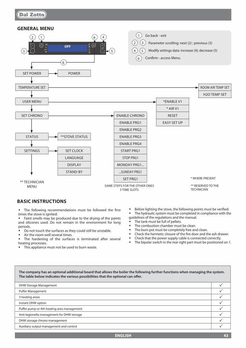
OFF12
3
4
5
6
1
2 3
4 5
6
12
3
46
5
6
ENGLISH
GENERAL MENUGo back - exit
Parameter scrolling: next (2) ; previous (3) Modify settings data: increase (4); decrease (5)
Con�rm - access Menu
SET POWER POWER
TEMPERATURE SET ROOM AIR TEMP SET
H2O TEMP SET
USER MENU *ENABLE V1
* AIR V1
SET CHRONO ENABLE CHRONO RESET
ENABLE PRG1 EASY SET UP
ENABLE PRG2
STATUS **STOVE STATUS ENABLE PRG3
ENABLE PRG4
SETTINGS SET CLOCK START PRG1
LANGUAGE STOP PRG1
DISPLAY MONDAY PRG1...
STAND-BY ...SUNDAY PRG1
** TECHNICIAN MENU
SET PRG1 * WHERE PRESENT
** RESERVED TO THE TECHNICIAN
SAME STEPS FOR THE OTHER ONES 3 TIME SLOTS
The company has an optional additional board that allows the boiler the following further functions when managing the system. The table below indicates the various possibilities that the optional can o�er.
DHW Storage Management pPu�er Management p3 heating areas pInstant DHW option pPu�er pump or 4th heating area management pAnti-legionella management for DHW storage pDHW storage chrono management pAuxiliary output management and control p
BASIC INSTRUCTIONS
� The following recommendations must be followed the �rst times the stove is ignited:� Faint smells may be produced due to the drying of the paints and silicones used. Do not remain in the environment for long periods.� Do not touch the surfaces as they could still be unstable.� Air the room well several times.� The hardening of the surfaces is terminated after several heating processes.� This appliance must not be used to burn waste.
� Before lighting the stove, the following points must be veri�ed:� The hydraulic system must be completed in compliance with the guidelines of the regulations and the manual.� The tank must be full of pellets.� The combustion chamber must be clean.� The burn pot must be completely free and clean.� Check the hermetic closure of the �re door and the ash drawer.� Check that the power supply cable is connected correctly.� The bipolar switch in the rear right part must be positioned on 1.
43

ENGLISH
THE REMOTE CONTROLAll that can normally be implemented through the LCD can be adjusted using the remote control.The table below provides a detailed description of the various functions:
INFO
1
2
3
4
5
6
7
8
9
10
11 12 13
14 15 16
1 ON / OFF Pressing the key for three seconds, the stove will switch on or o�
2 POWER INCREASE Pressing the key will increase the operating power
3 POWER DECREASE Pressing the key will decrease the operating power
4 T° INCREASE The temperature setting can be increased by pressing this key
5 T° DECREASE The set temperature can be decreased by pressing this key
6 ENABLE / DISABLE CHRONO Pressing the key once will enable or disable the chrono
7 ENABLE DELAYED SWITCH-OFF
The delayed switch-o� can be set by pressing this key. For example, if the stove is set to switch-o� in an hour, it shall switch-o� automatically once the set time elapses, displaying the countdown every minute for delayed automatic shutdown.
8 MENU This key allows the user to access the user and technical menu (the technical menu is reserved for assistance)
9 INCREASE The temperature setting can be increased by pressing this key
10 ESC KEY The key allows the user to exit any program or display and returns to the main menu without saving the data
11 BACK The key returns to the display of the various menus
12 CONFIRMATION KEY This key con�rms the adjustments made during the user menu programming phase
13 FORWARD The key allows the user to go forward in the various menus
14 ENABLE FUNCTION F1 Pre-set key for future applications
15 DECREASE The key decreases the value to be set
16 STOVE STATUS Pressing this key will display the general status of the stove
TYPE AND REPLACEMENT OF BATTERIES
The batteries are housed in the lower part of the remote control. To replace it, you need to take out the battery holder, remove or insert the battery following the symbols on the remote control and on the battery.For operation, 1 CR2025, 3V lithium bu�er battery is required.
The batteries used contain metals harmful for the environment. They must therefore be disposed of separately in appropriate containers.
Important note: the numbers shown on the remote control are purely indicative and are not present on the remote control supplied with the product.
IF THE REMOTE CONTROL IS OFF BECAUSE IT HAS NO BATTERIES, THE STOVE CAN BE CONTROLLED FROM THE CONTROL PANEL ON TOP OF IT. WHILE REPLACING THE BATTERY, PAY ATTENTION TO THE POLARITY BY OBSERVING THE SYMBOL ON THE INSIDE COMPARTMENT OF THE REMOTE CONTROL.
J
ALL CLEAN CHECK UP
SHOULD THE "ALL CLEAN CHECK UP" ALARM BE TRIGGERED, MAKE SURE THAT THE BOTTOM OF THE BURN POT IS FREE OF RESIDUES OR SCALES. THE HOLES AT THE BOTTOM MUST BE COMPLETELY FREE TO GUARANTEE CORRECT COMBUSTION. ONE CAN USE THE FUNCTION TO ADJUST COMBUSTION BASED ON THE DESCRIBED REQUIREMENTS. IF THE ALARM PERSISTS AND THE ABOVE LISTED CONDITIONS HAVE BEEN CHECKED, CONTACT THE QUALIFIED AFTER-SALES ASSISTANCE CENTRE.
BURN POT BOTTOM
44
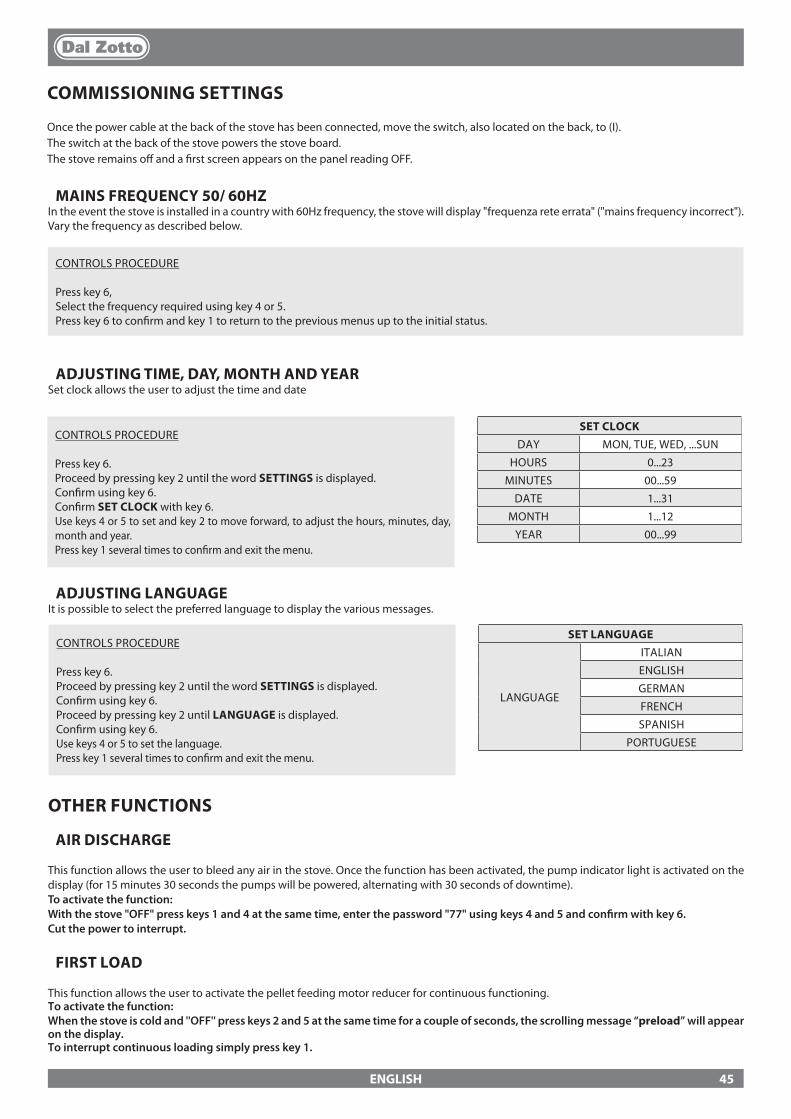
ENGLISH
ADJUSTING TIME, DAY, MONTH AND YEARSet clock allows the user to adjust the time and date
CONTROLS PROCEDURE
Press key 6.Proceed by pressing key 2 until the word SETTINGS is displayed.Con�rm using key 6.Proceed by pressing key 2 until LANGUAGE is displayed.Con�rm using key 6.Use keys 4 or 5 to set the language.Press key 1 several times to con�rm and exit the menu.
SET LANGUAGE
LANGUAGE
ITALIAN
ENGLISH
GERMAN
FRENCH
SPANISH
PORTUGUESE
COMMISSIONING SETTINGS
Once the power cable at the back of the stove has been connected, move the switch, also located on the back, to (I).The switch at the back of the stove powers the stove board.The stove remains o� and a �rst screen appears on the panel reading OFF.
OTHER FUNCTIONS
AIR DISCHARGE
This function allows the user to bleed any air in the stove. Once the function has been activated, the pump indicator light is activated on the display (for 15 minutes 30 seconds the pumps will be powered, alternating with 30 seconds of downtime).To activate the function:With the stove "OFF" press keys 1 and 4 at the same time, enter the password "77" using keys 4 and 5 and con�rm with key 6. Cut the power to interrupt.
FIRST LOAD
This function allows the user to activate the pellet feeding motor reducer for continuous functioning. To activate the function:When the stove is cold and ''OFF'' press keys 2 and 5 at the same time for a couple of seconds, the scrolling message “preload” will appear on the display.To interrupt continuous loading simply press key 1.
CONTROLS PROCEDURE
Press key 6.Proceed by pressing key 2 until the word SETTINGS is displayed.Con�rm using key 6.Con�rm SET CLOCK with key 6.Use keys 4 or 5 to set and key 2 to move forward, to adjust the hours, minutes, day, month and year.Press key 1 several times to con�rm and exit the menu.
SET CLOCKDAY MON, TUE, WED, ...SUN
HOURS 0...23
MINUTES 00...59
DATE 1...31
MONTH 1...12
YEAR 00...99
ADJUSTING LANGUAGEIt is possible to select the preferred language to display the various messages.
MAINS FREQUENCY 50/ 60HZIn the event the stove is installed in a country with 60Hz frequency, the stove will display "frequenza rete errata" ("mains frequency incorrect").Vary the frequency as described below.
CONTROLS PROCEDURE
Press key 6, Select the frequency required using key 4 or 5.Press key 6 to con�rm and key 1 to return to the previous menus up to the initial status.
45
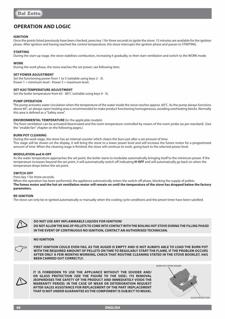
ENGLISH
OPERATION AND LOGIC
IGNITIONOnce the points listed previously have been checked, press key 1 for three seconds to ignite the stove. 15 minutes are available for the ignition phase. After ignition and having reached the control temperature, the stove interrupts the ignition phase and passes to STARTING.
STARTINGDuring the start-up stage, the stove stabilises combustion, increasing it gradually, to then start ventilation and switch to the WORK mode.
WORKDuring the work phase, the stove reaches the set power; see following item.
SET POWER ADJUSTMENTSet the functioning power from 1 to 5 (settable using keys 2 - 3).Power 1 = minimum level - Power 5 = maximum level.
SET H2O TEMPERATURE ADJUSTMENTSet the boiler temperature from 65 - 80°C (settable using keys 4 - 5).
PUMP OPERATIONThe pump activates water circulation when the temperature of the water inside the stove reaches approx. 60°C. As the pump always functions above 60°, an always-open heating area is recommended to make product functioning homogeneous, avoiding overheating blocks. Normally this area is de�ned as a “Safety zone”.
ENVIRONMENTAL TEMPERATURE (in the applicable models)The front ventilation can be activated/deactivated and the room temperature controlled by means of the room probe (as per standard). (See the ''enable fan'' chapter on the following pages.)
BURN POT CLEANINGDuring the work stage, the stove has an internal counter which cleans the burn pot after a set amount of time.This stage will be shown on the display, it will bring the stove to a lower power level and will increase the fumes motor for a programmed amount of time. When the cleaning stage is �nished, the stove will continue its work, going back to the selected power level.
MODULATION and H-OFFAs the water temperature approaches the set point, the boiler starts to modulate automatically bringing itself to the minimum power. If the temperature increases beyond the set point, it will automatically switch o� indicating H-OFF and will automatically go back on when the temperature drops below the set point.
SWITCH-OFFPress key 1 for three seconds.When the operation has been performed, the appliance automatically enters the switch-o� phase, blocking the supply of pellets.The fumes motor and the hot air ventilation motor will remain on until the temperature of the stove has dropped below the factory parameters.
RE-IGNITIONThe stove can only be re-ignited automatically or manually when the cooling cycle conditions and the preset timer have been satis�ed.
J NO IGNITION
FIRST IGNITION COULD EVEN FAIL AS THE AUGER IS EMPTY AND IS NOT ALWAYS ABLE TO LOAD THE BURN POT WITH THE REQUIRED AMOUNT OF PELLETS ON TIME TO REGULARLY START THE FLAME. IF THE PROBLEM OCCURS AFTER ONLY A FEW MONTHS WORKING, CHECK THAT ROUTINE CLEANING STATED IN THE STOVE BOOKLET, HAS BEEN CARRIED OUT CORRECTLY.
DO NOT USE ANY INFLAMMABLE LIQUIDS FOR IGNITION!DO NOT ALLOW THE BAG OF PELLETS TO COME INTO CONTACT WITH THE BOILING HOT STOVE DURING THE FILLING PHASE!IN THE EVENT OF CONTINUOUS NO IGNITION, CONTACT AN AUTHORISED TECHNICIAN.
IT IS FORBIDDEN TO USE THE APPLIANCE WITHOUT THE DIVIDER AND/OR GLASS PROTECTION (SEE THE FIGURE TO THE SIDE). ITS REMOVAL JEOPARDISES THE SAFETY OF THE PRODUCT AND IMMEDIATELY VOIDS THE WARRANTY PERIOD. IN THE CASE OF WEAR OR DETERIORATION REQUEST AFTER-SALES ASSISTANCE FOR REPLACEMENT OF THE PART (REPLACEMENT THAT IS NOT UNDER GUARANTEE AS THE COMPONENT IS SUBJECT TO WEAR).
BURN POT UPPER DIVIDER
GLASS PROTECTION
46
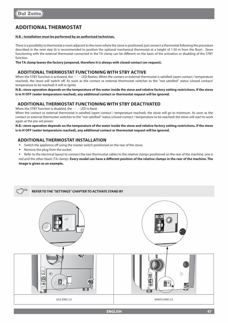
JOLE IDRO 2.0 MARTA IDRO 2.0
ENGLISH
ADDITIONAL THERMOSTAT
N.B. : Installation must be performed by an authorised technician.
There is a possibility to thermostat a room adjacent to the room where the stove is positioned: just connect a thermostat following the procedure described in the next step (it is recommended to position the optional mechanical thermostat at a height of 1.50 m from the �oor) . Stove functioning with the external thermostat connected in the TA clamp can be di�erent on the basis of the activation or disabling of the STBY function.The TA clamp leaves the factory jumpered, therefore it is always with closed contact (on request).
ADDITIONAL THERMOSTAT FUNCTIONING WITH STBY ACTIVEWhen the STBY function is activated, the LED �ashes. When the contact or external thermostat is satis�ed (open contact / temperature reached), the stove will switch o�. As soon as the contact or external thermostat switches to the "not satis�ed" status (closed contact/temperature to be reached) it will re-ignite.N.B.: stove operation depends on the temperature of the water inside the stove and relative factory setting restrictions. If the stove is in H OFF (water temperature reached), any additional contact or thermostat request will be ignored.
ADDITIONAL THERMOSTAT FUNCTIONING WITH STBY DEACTIVATEDWhen the STBY function is disabled, the LED is �xed.When the contact or external thermostat is satis�ed (open contact / temperature reached), the stove will go to minimum. As soon as the contact or external thermostat switches to the "not satis�ed" status (closed contact / temperature to be reached) the stove will start to work again at the pre-set power. N.B.: stove operation depends on the temperature of the water inside the stove and relative factory setting restrictions. If the stove is in H OFF (water temperature reached), any additional contact or thermostat request will be ignored.
ADDITIONAL THERMOSTAT INSTALLATION� Switch the appliance o� using the master switch positioned on the rear of the stove.� Remove the plug from the socket.� Refer to the electrical layout to connect the two thermostat cables to the relative clamps positioned on the rear of the machine, one is red and the other black (TA clamp). Every model can have a di�erent position of the relative clamps in the rear of the machine. The image is given as an example.
J
REFER TO THE ''SETTINGS'' CHAPTER TO ACTIVATE STAND BY
47
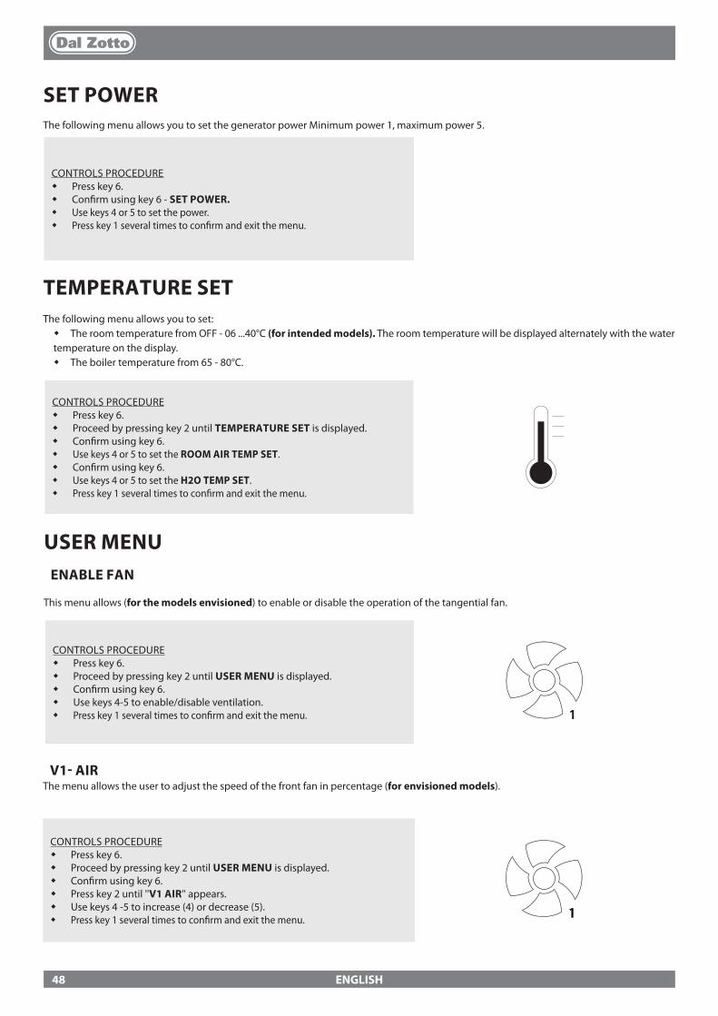
ENGLISH
SET POWERThe following menu allows you to set the generator power Minimum power 1, maximum power 5.
CONTROLS PROCEDURE� Press key 6.� Con�rm using key 6 - SET POWER.� Use keys 4 or 5 to set the power.� Press key 1 several times to con�rm and exit the menu.
TEMPERATURE SETThe following menu allows you to set:� The room temperature from OFF - 06 ...40°C (for intended models). The room temperature will be displayed alternately with the water temperature on the display.� The boiler temperature from 65 - 80°C.
CONTROLS PROCEDURE� Press key 6.� Proceed by pressing key 2 until TEMPERATURE SET is displayed.� Con�rm using key 6.� Use keys 4 or 5 to set the ROOM AIR TEMP SET.� Con�rm using key 6.� Use keys 4 or 5 to set the H2O TEMP SET.� Press key 1 several times to con�rm and exit the menu.
USER MENUENABLE FAN
This menu allows (for the models envisioned) to enable or disable the operation of the tangential fan.
CONTROLS PROCEDURE� Press key 6.� Proceed by pressing key 2 until USER MENU is displayed.� Con�rm using key 6.� Use keys 4-5 to enable/disable ventilation.� Press key 1 several times to con�rm and exit the menu. 1
V1- AIRThe menu allows the user to adjust the speed of the front fan in percentage (for envisioned models).
CONTROLS PROCEDURE� Press key 6.� Proceed by pressing key 2 until USER MENU is displayed.� Con�rm using key 6.� Press key 2 until ''V1 AIR'' appears.� Use keys 4 -5 to increase (4) or decrease (5).� Press key 1 several times to con�rm and exit the menu. 1
48

ENGLISH
CONTROLS PROCEDURE� Press key 6.� Proceed by pressing key 2 until USER MENU is displayed.� Con�rm using key 6.� Press key 2 until RESET is displayed.� Press keys 4-5 to select ON and press key 6.� ''DONE'' will appear on the display to con�rm
EASY SET UPThe volumetric weight of the pellet is the ratio between the weight and the volume of the pellet. This ratio may change while maintaining the quality of the pellet. Using the EASY SET UP function, it is possible to vary the calibration of the volumetric weight by increasing or decreasing the pre-set values.In the stove program, the values available range from “– 3” to “+ 3”; all the stoves are calibrated in production with the optimal value of 0.Where excessive depositing on the burn pot is evident, enter the EASY SET UP program and lower the value of a unit to "- 1" then wait until the following day and if there is no improvement decrease further to a maximum of "- 3". Where instead it is necessary to increase the calibration of the volumetric weight of the pellet, change the default value of “0” to “+ 1, + 2 or + 3” according to requirement.
RESET
Allows the user to reset all values modi�able by the user to the default values.
EXCESSIVE DEPOSITING OF PELLET IN THE BURN POT NORMAL OPERATION LOW DEPOSITING OF PELLET IN THE BURN POT
-3 -2 -1 0 +1 +2 +3
THIRD RANGE OF DECREASE IF THE FIRST TWO ARE INSUFFICIENT
SECOND RANGE OF DECREASE IF THE FIRST IS INSUFFICIENT
FIRST RANGE OF DECREASE (TEST
FOR 1 DAY)
OPTIMAL FACTORY VALUE
FIRST INCREASE RANGE
SECOND INCREASE RANGE IF THE
FIRST IS INSUFFI-CIENT
THIRD RANGE OF INCREASE IF THE FIRST TWO ARE INSUFFICIENT
SET CHRONOThis stage is used to program when the generator automatically turns on and o�.The factory setting for SET CHRONO is disabled on the generator.The chrono allows the user to program 4 time spans within a day to use every day of the week. The switch-on and switch-o� time can be set in every time slot, along with the days of use of the programmed time slot and the desired water temperature (65 - 80°C). The setting of the current day and time is essential to ensure the chrono operates correctly.
RECOMMENDATIONSBefore using the chrono function, set the current day and time. Therefore check that the points listed in the “Set clock” sub-chapter have been followed, so that the chrono function works. Aside from programming it, activate it as well. The ignition and switch-o� times must be within the arc of one day, from 0 to 24 and not over several days.
CORRECT INCORRECT
Switch-on time 07:00Switch-o� time 18:00
Switch-on time 22:00Switch-o� time 05:00
Example:
N.B.: Where these settings do not correct pellet depositing in the burn pot, please contact your local support centre.
CONTROL PROCEDURE� Press the 6 key.� Continue pressing the 2 key until you see USER MENU.� Con�rm with the 6 key.� Press the 2 key until you see "EASY SET UP".� Use the 4-5 keys to increase (4) or decrease (5) the load during the WORK phase.� Press the 1 key several times to con�rm and exit the menu.
49
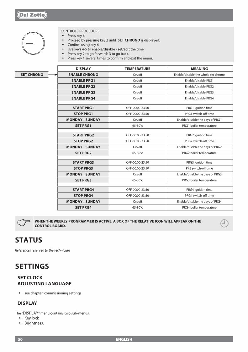
ENGLISH
JWHEN THE WEEKLY PROGRAMMER IS ACTIVE, A BOX OF THE RELATIVE ICON WILL APPEAR ON THE CONTROL BOARD.
DISPLAY TEMPERATURE MEANING
SET CHRONO ENABLE CHRONO On/o� Enable/disable the whole set chrono
ENABLE PRG1 On/o� Enable/disable PRG1
ENABLE PRG2 On/o� Enable/disable PRG2
ENABLE PRG3 On/o� Enable/disable PRG3
ENABLE PRG4 On/o� Enable/disable PRG4
START PRG1 OFF-00:00-23:50 PRG1 ignition time
STOP PRG1 OFF-00:00-23:50 PRG1 switch-o� time
MONDAY...SUNDAY On/o� Enable/disable the days of PRG1
SET PRG1 65-80°c PRG1 boiler temperature
START PRG2 OFF-00:00-23:50 PRG2 ignition time
STOP PRG2 OFF-00:00-23:50 PRG2 switch-o� time
MONDAY...SUNDAY On/o� Enable/disable the days of PRG2
SET PRG2 65-80°c PRG2 boiler temperature
START PRG3 OFF-00:00-23:50 PRG3 ignition time
STOP PRG3 OFF-00:00-23:50 PR3 switch-o� time
MONDAY...SUNDAY On/o� Enable/disable the days of PRG3
SET PRG3 65-80°c PRG3 boiler temperature
START PRG4 OFF-00:00-23:50 PRG4 ignition time
STOP PRG4 OFF-00:00-23:50 PRG4 switch-o� time
MONDAY...SUNDAY On/o� Enable/disable the days of PRG4
SET PRG4 65-80°c PRG4 boiler temperature
CONTROLS PROCEDURE� Press key 6.�Proceed by pressing key 2 until SET CHRONO is displayed.� Con�rm using key 6.� Use keys 4-5 to enable/disable - set/edit the time.� Press key 2 to go forwards 3 to go back.� Press key 1 several times to con�rm and exit the menu.
STATUSReferences reserved to the technician
SETTINGSSET CLOCK ADJUSTING LANGUAGE
� see chapter: commissioning settings
DISPLAY
The "DISPLAY" menu contains two sub-menus:� Key lock� Brightness.
50
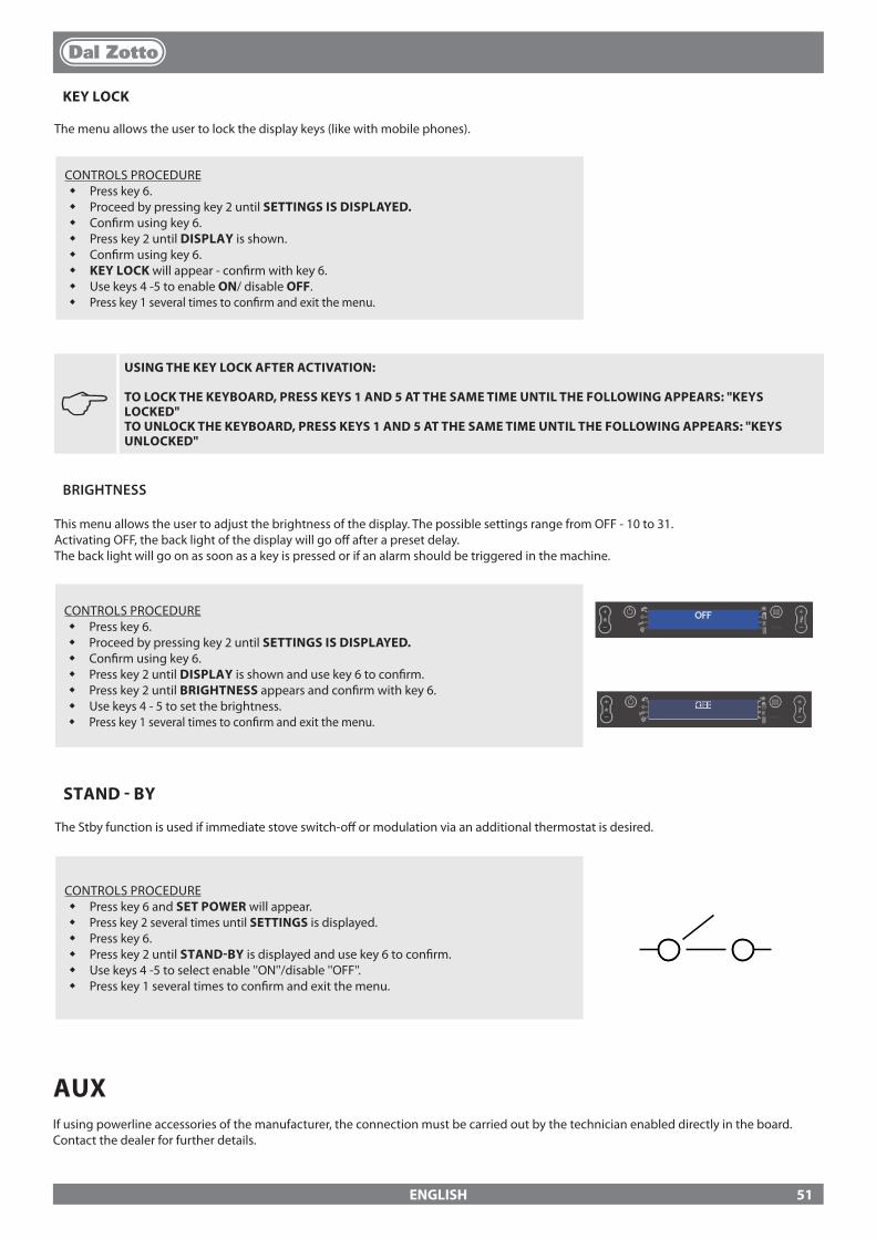
ENGLISH
J USING THE KEY LOCK AFTER ACTIVATION:
TO LOCK THE KEYBOARD, PRESS KEYS 1 AND 5 AT THE SAME TIME UNTIL THE FOLLOWING APPEARS: "KEYS LOCKED" TO UNLOCK THE KEYBOARD, PRESS KEYS 1 AND 5 AT THE SAME TIME UNTIL THE FOLLOWING APPEARS: "KEYS UNLOCKED"
BRIGHTNESS
This menu allows the user to adjust the brightness of the display. The possible settings range from OFF - 10 to 31.Activating OFF, the back light of the display will go o� after a preset delay. The back light will go on as soon as a key is pressed or if an alarm should be triggered in the machine.
CONTROLS PROCEDURE� Press key 6.�Proceed by pressing key 2 until SETTINGS IS DISPLAYED.� Con�rm using key 6.� Press key 2 until DISPLAY is shown and use key 6 to con�rm.� Press key 2 until BRIGHTNESS appears and con�rm with key 6.�Use keys 4 - 5 to set the brightness.� Press key 1 several times to con�rm and exit the menu.
OFF
OFF
KEY LOCK
The menu allows the user to lock the display keys (like with mobile phones).
CONTROLS PROCEDURE� Press key 6.�Proceed by pressing key 2 until SETTINGS IS DISPLAYED.� Con�rm using key 6.�Press key 2 until DISPLAY is shown.�Con�rm using key 6.� KEY LOCK will appear - con�rm with key 6.� Use keys 4 -5 to enable ON/ disable OFF.� Press key 1 several times to con�rm and exit the menu.
STAND - BY
The Stby function is used if immediate stove switch-o� or modulation via an additional thermostat is desired.
CONTROLS PROCEDURE� Press key 6 and SET POWER will appear.� Press key 2 several times until SETTINGS is displayed.� Press key 6.�Press key 2 until STAND-BY is displayed and use key 6 to con�rm.� Use keys 4 -5 to select enable ''ON''/disable ''OFF''.� Press key 1 several times to con�rm and exit the menu.
AUXIf using powerline accessories of the manufacturer, the connection must be carried out by the technician enabled directly in the board.Contact the dealer for further details.
51
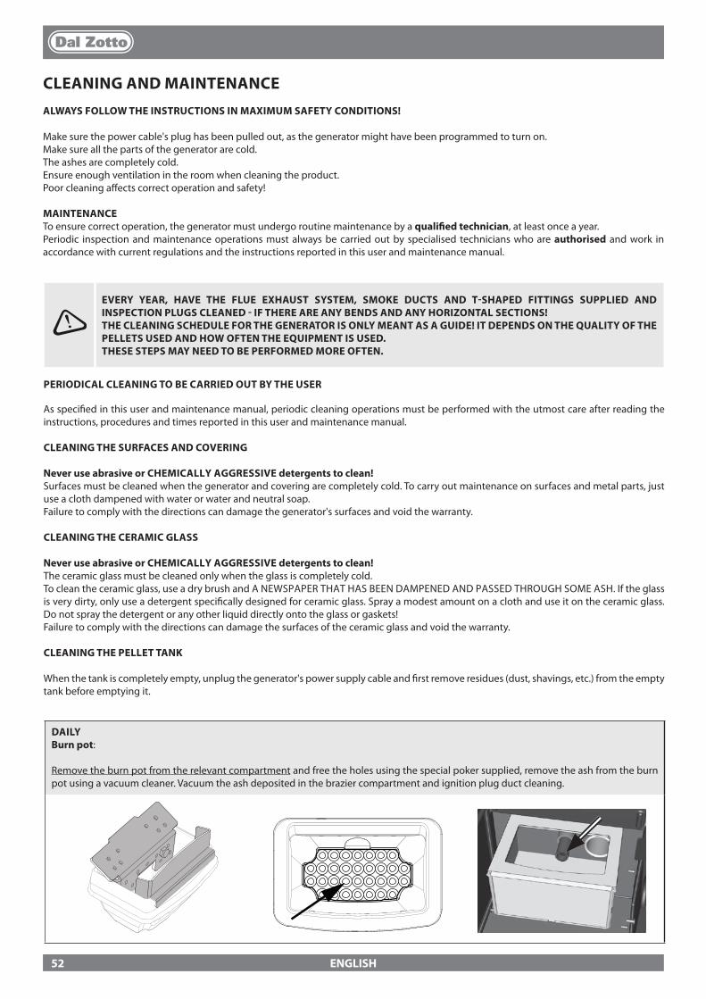
ENGLISH
CLEANING AND MAINTENANCEALWAYS FOLLOW THE INSTRUCTIONS IN MAXIMUM SAFETY CONDITIONS!
Make sure the power cable's plug has been pulled out, as the generator might have been programmed to turn on. Make sure all the parts of the generator are cold.The ashes are completely cold.Ensure enough ventilation in the room when cleaning the product.Poor cleaning a�ects correct operation and safety!
MAINTENANCETo ensure correct operation, the generator must undergo routine maintenance by a quali�ed technician, at least once a year.Periodic inspection and maintenance operations must always be carried out by specialised technicians who are authorised and work in accordance with current regulations and the instructions reported in this user and maintenance manual.
DAILY Burn pot:
Remove the burn pot from the relevant compartment and free the holes using the special poker supplied, remove the ash from the burn pot using a vacuum cleaner. Vacuum the ash deposited in the brazier compartment and ignition plug duct cleaning.
EVERY YEAR, HAVE THE FLUE EXHAUST SYSTEM, SMOKE DUCTS AND T-SHAPED FITTINGS SUPPLIED AND INSPECTION PLUGS CLEANED - IF THERE ARE ANY BENDS AND ANY HORIZONTAL SECTIONS!THE CLEANING SCHEDULE FOR THE GENERATOR IS ONLY MEANT AS A GUIDE! IT DEPENDS ON THE QUALITY OF THE PELLETS USED AND HOW OFTEN THE EQUIPMENT IS USED. THESE STEPS MAY NEED TO BE PERFORMED MORE OFTEN.
PERIODICAL CLEANING TO BE CARRIED OUT BY THE USER
As speci�ed in this user and maintenance manual, periodic cleaning operations must be performed with the utmost care after reading the instructions, procedures and times reported in this user and maintenance manual.
CLEANING THE SURFACES AND COVERING
Never use abrasive or CHEMICALLY AGGRESSIVE detergents to clean!Surfaces must be cleaned when the generator and covering are completely cold. To carry out maintenance on surfaces and metal parts, just use a cloth dampened with water or water and neutral soap.Failure to comply with the directions can damage the generator's surfaces and void the warranty.
CLEANING THE CERAMIC GLASS
Never use abrasive or CHEMICALLY AGGRESSIVE detergents to clean!The ceramic glass must be cleaned only when the glass is completely cold. To clean the ceramic glass, use a dry brush and A NEWSPAPER THAT HAS BEEN DAMPENED AND PASSED THROUGH SOME ASH. If the glass is very dirty, only use a detergent speci�cally designed for ceramic glass. Spray a modest amount on a cloth and use it on the ceramic glass. Do not spray the detergent or any other liquid directly onto the glass or gaskets!Failure to comply with the directions can damage the surfaces of the ceramic glass and void the warranty.
CLEANING THE PELLET TANK
When the tank is completely empty, unplug the generator's power supply cable and �rst remove residues (dust, shavings, etc.) from the empty tank before emptying it.
52
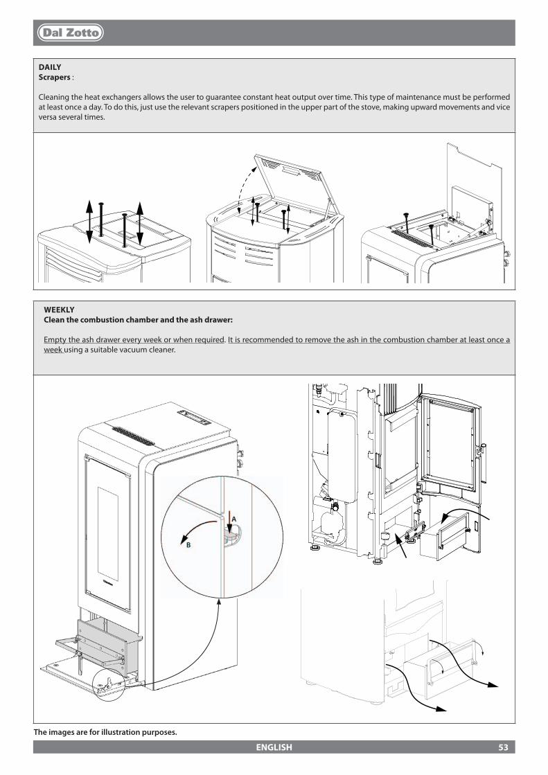
ENGLISH
DAILYScrapers :
Cleaning the heat exchangers allows the user to guarantee constant heat output over time. This type of maintenance must be performed at least once a day. To do this, just use the relevant scrapers positioned in the upper part of the stove, making upward movements and vice versa several times.
WEEKLY Clean the combustion chamber and the ash drawer:
Empty the ash drawer every week or when required. It is recommended to remove the ash in the combustion chamber at least once a week using a suitable vacuum cleaner.
The images are for illustration purposes.
53
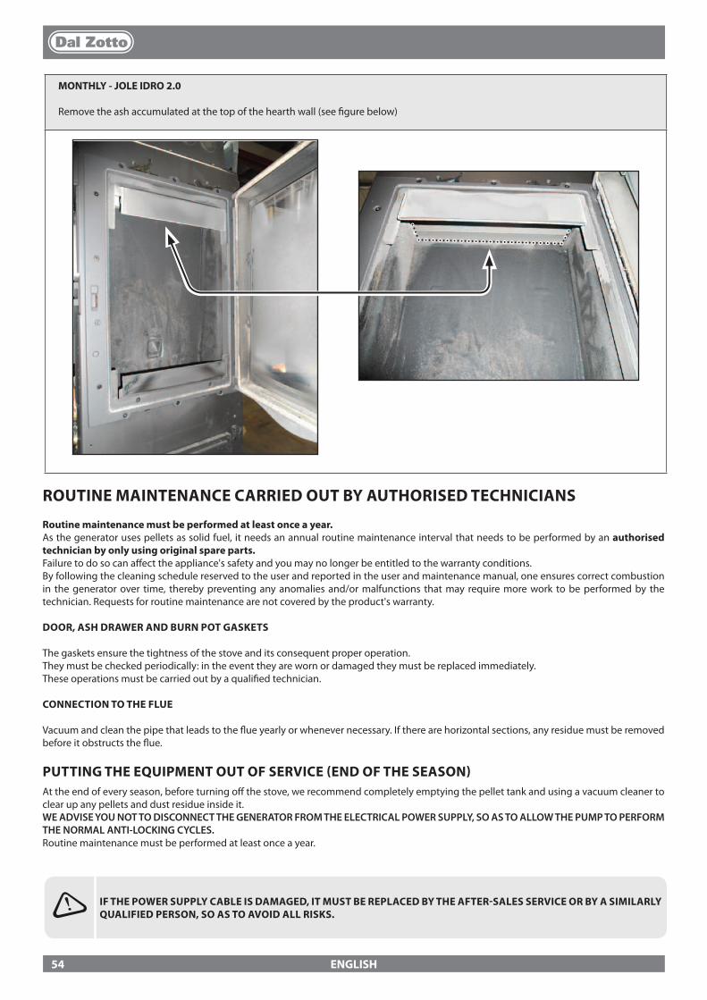
ENGLISH
ROUTINE MAINTENANCE CARRIED OUT BY AUTHORISED TECHNICIANS
Routine maintenance must be performed at least once a year.As the generator uses pellets as solid fuel, it needs an annual routine maintenance interval that needs to be performed by an authorised technician by only using original spare parts.Failure to do so can a�ect the appliance's safety and you may no longer be entitled to the warranty conditions.By following the cleaning schedule reserved to the user and reported in the user and maintenance manual, one ensures correct combustion in the generator over time, thereby preventing any anomalies and/or malfunctions that may require more work to be performed by the technician. Requests for routine maintenance are not covered by the product's warranty.
DOOR, ASH DRAWER AND BURN POT GASKETS
The gaskets ensure the tightness of the stove and its consequent proper operation.They must be checked periodically: in the event they are worn or damaged they must be replaced immediately.These operations must be carried out by a quali�ed technician.
CONNECTION TO THE FLUE
Vacuum and clean the pipe that leads to the �ue yearly or whenever necessary. If there are horizontal sections, any residue must be removed before it obstructs the �ue.
PUTTING THE EQUIPMENT OUT OF SERVICE (END OF THE SEASON)At the end of every season, before turning o� the stove, we recommend completely emptying the pellet tank and using a vacuum cleaner to clear up any pellets and dust residue inside it.WE ADVISE YOU NOT TO DISCONNECT THE GENERATOR FROM THE ELECTRICAL POWER SUPPLY, SO AS TO ALLOW THE PUMP TO PERFORM THE NORMAL ANTI-LOCKING CYCLES.Routine maintenance must be performed at least once a year.
IF THE POWER SUPPLY CABLE IS DAMAGED, IT MUST BE REPLACED BY THE AFTER-SALES SERVICE OR BY A SIMILARLY QUALIFIED PERSON, SO AS TO AVOID ALL RISKS.
MONTHLY - JOLE IDRO 2.0
Remove the ash accumulated at the top of the hearth wall (see �gure below)
54
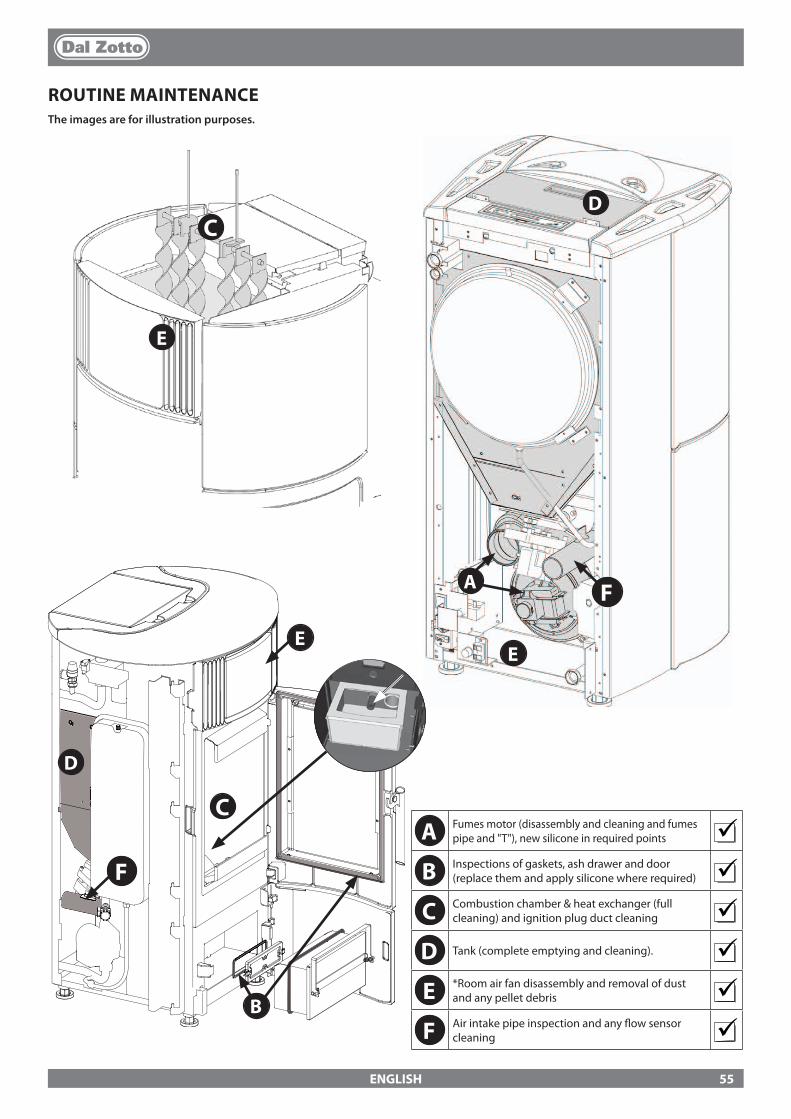
B
E
D
C
A
C
F
D
EE
F
ENGLISH
ROUTINE MAINTENANCEThe images are for illustration purposes.
A Fumes motor (disassembly and cleaning and fumes pipe and "T"), new silicone in required points
B Inspections of gaskets, ash drawer and door (replace them and apply silicone where required)
C Combustion chamber & heat exchanger (full cleaning) and ignition plug duct cleaning
D Tank (complete emptying and cleaning). E *Room air fan disassembly and removal of dust
and any pellet debris F Air intake pipe inspection and any �ow sensor
cleaning
55
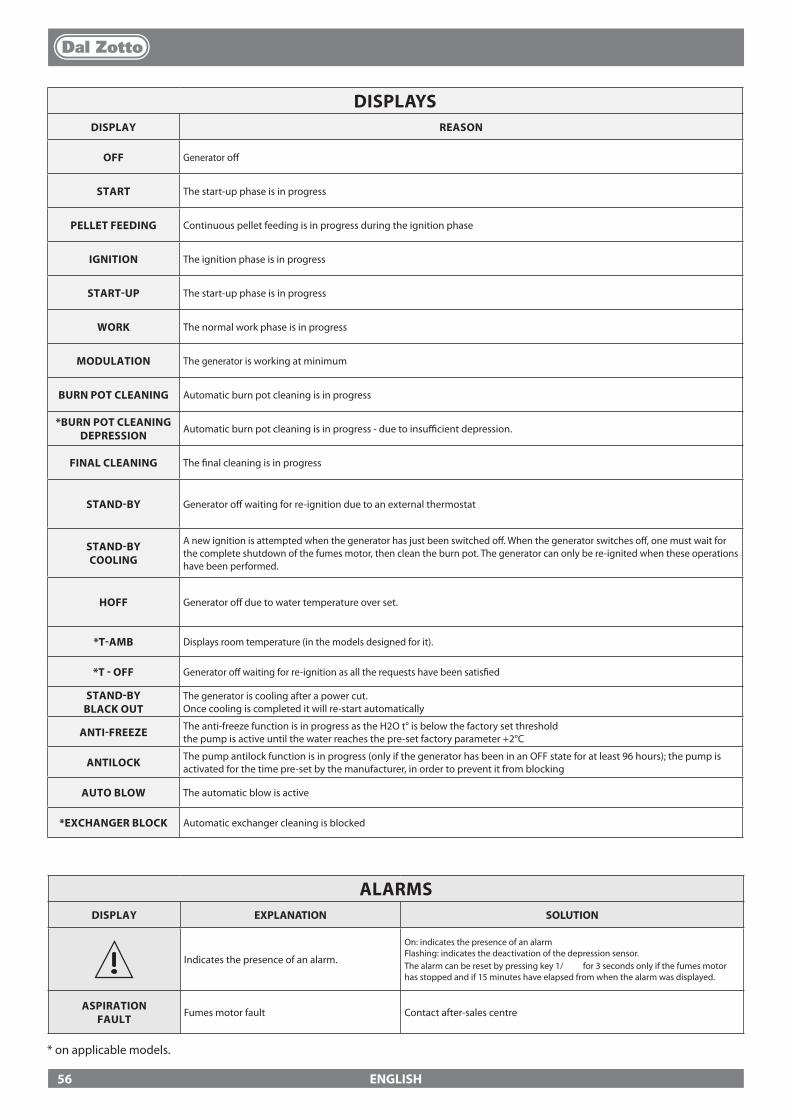
ENGLISH
DISPLAYSDISPLAY REASON
OFF Generator o�
START The start-up phase is in progress
PELLET FEEDING Continuous pellet feeding is in progress during the ignition phase
IGNITION The ignition phase is in progress
START-UP The start-up phase is in progress
WORK The normal work phase is in progress
MODULATION The generator is working at minimum
BURN POT CLEANING Automatic burn pot cleaning is in progress
*BURN POT CLEANINGDEPRESSION
Automatic burn pot cleaning is in progress - due to insu�cient depression.
FINAL CLEANING The �nal cleaning is in progress
STAND-BY Generator o� waiting for re-ignition due to an external thermostat
STAND-BY COOLING
A new ignition is attempted when the generator has just been switched o�. When the generator switches o�, one must wait for the complete shutdown of the fumes motor, then clean the burn pot. The generator can only be re-ignited when these operations have been performed.
HOFF Generator o� due to water temperature over set.
*T-AMB Displays room temperature (in the models designed for it).
*T - OFF Generator o� waiting for re-ignition as all the requests have been satis�ed
STAND-BY BLACK OUT
The generator is cooling after a power cut. Once cooling is completed it will re-start automatically
ANTI-FREEZE The anti-freeze function is in progress as the H2O t° is below the factory set thresholdthe pump is active until the water reaches the pre-set factory parameter +2°C
ANTILOCK The pump antilock function is in progress (only if the generator has been in an OFF state for at least 96 hours); the pump is activated for the time pre-set by the manufacturer, in order to prevent it from blocking
AUTO BLOW The automatic blow is active
*EXCHANGER BLOCK Automatic exchanger cleaning is blocked
ALARMSDISPLAY EXPLANATION SOLUTION
Indicates the presence of an alarm.
On: indicates the presence of an alarmFlashing: indicates the deactivation of the depression sensor.The alarm can be reset by pressing key 1/ for 3 seconds only if the fumes motor has stopped and if 15 minutes have elapsed from when the alarm was displayed.
ASPIRATION FAULT
Fumes motor fault Contact after-sales centre
* on applicable models.
56
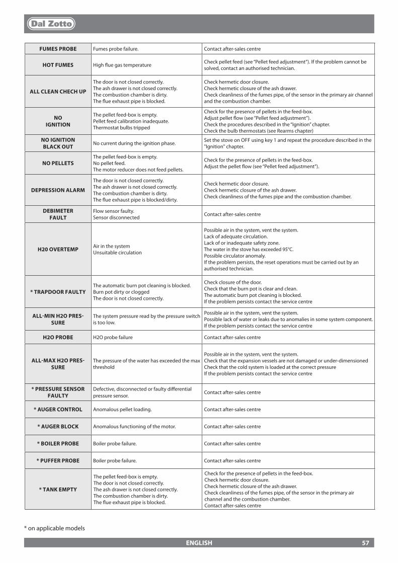
ENGLISH
* on applicable models
FUMES PROBE Fumes probe failure. Contact after-sales centre
HOT FUMES High �ue gas temperature Check pellet feed (see “Pellet feed adjustment”). If the problem cannot be solved, contact an authorised technician.
ALL CLEAN CHECH UP
The door is not closed correctly.The ash drawer is not closed correctly.The combustion chamber is dirty.The �ue exhaust pipe is blocked.
Check hermetic door closure.Check hermetic closure of the ash drawer.Check cleanliness of the fumes pipe, of the sensor in the primary air channel and the combustion chamber.
NO IGNITION
The pellet feed-box is empty.Pellet feed calibration inadequate.Thermostat bulbs tripped
Check for the presence of pellets in the feed-box.Adjust pellet �ow (see “Pellet feed adjustment”).Check the procedures described in the “Ignition” chapter.Check the bulb thermostats (see Rearms chapter)
NO IGNITION BLACK OUT
No current during the ignition phase. Set the stove on OFF using key 1 and repeat the procedure described in the "Ignition" chapter.
NO PELLETS The pellet feed-box is empty.No pellet feed.The motor reducer does not feed pellets.
Check for the presence of pellets in the feed-box.Adjust the pellet �ow (see “Pellet feed adjustment”).
DEPRESSION ALARM
The door is not closed correctly.The ash drawer is not closed correctly.The combustion chamber is dirty.The �ue exhaust pipe is blocked/dirty.
Check hermetic door closure.Check hermetic closure of the ash drawer.Check cleanliness of the fumes pipe and the combustion chamber.
DEBIMETER FAULT
Flow sensor faulty.Sensor disconnected Contact after-sales centre
H20 OVERTEMP Air in the systemUnsuitable circulation
Possible air in the system, vent the system.Lack of adequate circulation.Lack of or inadequate safety zone.The water in the stove has exceeded 95°C. Possible circulator anomaly.If the problem persists, the reset operations must be carried out by an authorised technician.
* TRAPDOOR FAULTYThe automatic burn pot cleaning is blocked. Burn pot dirty or cloggedThe door is not closed correctly.
Check closure of the door.Check that the burn pot is clear and clean.The automatic burn pot cleaning is blocked.If the problem persists contact the service centre
ALL-MIN H2O PRES-SURE
The system pressure read by the pressure switch is too low.
Possible air in the system, vent the system.Possible lack of water or leaks due to anomalies in some system component.If the problem persists contact the service centre
H2O PROBE H2O probe failure Contact after-sales centre
ALL-MAX H2O PRES-SURE
The pressure of the water has exceeded the max threshold
Possible air in the system, vent the system.Check that the expansion vessels are not damaged or under-dimensionedCheck that the cold system is loaded at the correct pressureIf the problem persists contact the service centre
* PRESSURE SENSOR FAULTY
Defective, disconnected or faulty di�erential pressure sensor.
Contact after-sales centre
* AUGER CONTROL Anomalous pellet loading. Contact after-sales centre
* AUGER BLOCK Anomalous functioning of the motor. Contact after-sales centre
* BOILER PROBE Boiler probe failure. Contact after-sales centre
* PUFFER PROBE Boiler probe failure. Contact after-sales centre
* TANK EMPTY
The pellet feed-box is empty. The door is not closed correctly.The ash drawer is not closed correctly.The combustion chamber is dirty.The �ue exhaust pipe is blocked.
Check for the presence of pellets in the feed-box.Check hermetic door closure.Check hermetic closure of the ash drawer.Check cleanliness of the fumes pipe, of the sensor in the primary air channel and the combustion chamber.Contact after-sales centre
57
ENGLISH
1. The DAL ZOTTO products (with La Nordica S.p.A. brand) are guaranteed, within the European community, for 24 months from the date of purchase. Purchase has to be proved by means of a valid �scal document issued by the seller (receipt, invoice or shipment document) identifying the purchased product and its purchase and/or delivery date.
WARNING: This conventional guarantee does not replace the guarantee regulated by the European legislation on consumer rights.
The conventional guarantee is only applicable to the Italian region and to those areas, within the European Community, where the Authorised Technical Assistance Centres are active (see the www.dalzotto.com website)It is also limited to the state of residence of the consumer, which must coincide with the premises and/or registered o�ce of the seller of the DAL ZOTTO product.These regulations do not apply if the product is purchased within commercial, entrepreneurial, or professional circumstances. In these cases the product guarantee will be limited to a period of 12 months from the date of purchase.
ITALIAN GUARANTEEWhat must be done if there is a product malfunction: Consult the instructions manual to make sure the malfunction cannot be solved by using the product correctly. Make sure the malfunction is included in those covered by the guarantee; otherwise the cost of the intervention will be borne entirely by the consumer. When requesting the intervention of the Assistance service at the Authorised Assistance Centre, always specify: - type of malfunction - model of the appliance - complete address - phone number
EUROPEAN GUARANTEEWhat must be done if there is a product malfunction: Consult the instructions manual to make sure the malfunction cannot be solved by using the product correctly. Make sure the malfunction is included in those covered by the guarantee; otherwise the cost of the intervention will be borne entirely by the consumer. Request the intervention of the Assistance service or the address of the Authorised Technical Assistance Centre to the seller; always specify: type of malfunction, model of the appliance, complete address and phone number
If the malfunction arises in the �rst 6 months of the product's life, the consumer has the right to have the product repaired with no expense. From the seventh to the twenty-fourth month, if a malfunction arises, the consumer will bear the cost of the call, while the seller will pay for the manpower and for any spare parts used.
2. If the malfunction is linked to external events and/or conditions such as, including but not limited to, insu�cient capacity of the systems; wrong installation and/or maintenance by the personnel which hasn't got the skills prescribed by the laws of the country of residence of the consumer; negligence; inability to use the product and wrong maintenance by the consumer, with respect to what is reported and recommended by the instructions manual of the product, which is part of the sales contract, this guarantee will be void. Damage to the product that cannot be related to manufacturing defects are also not included in this guarantee. Similarly are excluded defects related to incorrect operation of the �ue, according to the legislation in force in the country at the moment of purchase. Other exclusions include all product defects due to carelessness, accidental breakdown, tampering and/or damage during transport (scratches, dents, etc.), interventions carried out by unauthorised personnel and further damage caused by incorrect interventions by the consumer trying to arrange the initial malfunction. The following consumables are excluded by the guarantee: gaskets, ceramic or tempered glasses, cast iron grilles or coatings, refractory materials (e.g. Nordiker or others), painted, chrome-plated or golden parts, majolica ware, handles, the brazier and its related components. For Idro products the heat exchanger is not covered by the guarantee if a suitable condensation-proof circuit is not set up to ensure a return temperature of the device of at least 55°C. The guarantee excludes all the external components on which the consumer can directly operate during use and/or maintenance or that can be subject to wear and/or rust and stains on steel due to aggressive detergents. If malfunctions are signalled which are not later con�rmed during check by an authorised technician, the cost of the intervention will be borne entirely by the consumer.
3. If it is not possible to restore product conformity by repairing it, the product/component will be replaced, the guarantee expiration date and conditions will remain the same established when the product/component to be replaced has been purchased.
4. DAL ZOTTO (La Nordica S.p.A. brand) cannot be held liable for injury or damage which may - either directly or indirectly - be caused to persons, animals and property ensuing from failure to observe all the instructions provided in the relevant instruction manual and the warnings regarding installation, use and maintenance of the product, that can also be downloaded on the website.
5. Interventions for adjusting and/or regulating the product for the type of fuel or other reasons are excluded by the guarantee.
6. If the product is repaired in one of the Authorised Technical Assistance Centres indicated by DAL ZOTTO and if the product is replaced, transport will be free of charge. If the technician can repair the product at the user's place of residence and they refuse, transport to the workshop and redelivery will be paid by the consumer.
GUARANTEE TERMS
58
ENGLISH
7. After the 24 months of the guarantee have elapsed any repair intervention cost will be completely borne by the consumer.
8. In the case of disputes the only competent court is that of the DAL ZOTTO registered o�ce - (Vicenza - Italy)
ADDITIONAL WARNINGS
� Only use the fuel recommended by the manufacturer. The product must not be used as an incinerator. � Do not use the product as a ladder or supporting structure. � Do not place laundry on the product to dry it. Any clothes-horse or similar objects must be kept at due distance from the product.
Danger of �re or damage to the coating. � The user is fully liable for any incorrect use of the product. The manufacturer bears no civil or criminal liability for incorrect use. � Unauthorised tampering of any nature or replacement of spare parts of the product with non-original parts may endanger the operator
and the manufacturer bears no civil or criminal liability for this. � Large parts of the surface of the product can get very hot (door, handle, glass, smoke outlet pipes, etc.). Please therefore avoid coming
into contact with these parts without wearing suitable protective clothing or using appropriate measures, such as heat protective gloves. � DO NOT use the product with the door open or if the glass is broken. � The product must be electrically connected to a system equipped with an operational earthing system. � Turn o� the product in the event of a failure or malfunctioning. � Unburned pellets that build up in the burner following each failed start-up must be removed before attempting to start up the product
again. Make sure that the burner is clean and correctly positioned before starting it up again. � Do not wash the product with water. Water may penetrate into the unit and cause faults in the electrical insulation. This can cause
electric shocks. � Installations not complying with the regulations in force, as well as incorrect use and failure to comply with the maintenance scheduled
by the manufacturer, will invalidate the guarantee.
59
FRANCAIS
MISES EN GARDE
Ce manuel d'instructions fait partie intégrante du produit : s'assurer qu'il soit toujours avec l'appareil, même en cas de cession à un autre propriétaire ou utilisateur, ou en cas de transfert à un autre emplace-ment. Si ce manuel devait être abîmé ou perdu, en demander un autre exemplaire au service technique le plus proche. Ce produit doit être réservé à l'usage pour lequel il a expressément été réalisé. Toute responsabilité contractuelle et extracontractuelle du fabricant, en cas de dommages causés à des per-sonnes, animaux ou biens, dus à des erreurs d’installation, de réglage, d’entretien et d’utilisation incor-rects, est exclue.L'installation doit être exécutée par du personnel quali�é et autorisé, qui assumera toute la respon-sabilité de l'installation dé�nitive ainsi que du bon fonctionnement ultérieur du produit installé. Il faut respecter toutes les lois et règlementations nationales, régionales, provinciales et communales existant dans le pays où a été installé l’appareil, ainsi que les instructions contenues dans le présent manuel.En cas de non respect de ces précautions, le fabricant n'assume aucune responsabilité.Après avoir enlevé l’emballage, s’assurer que le contenu est intact et qu’il ne manque rien. Le cas échéant, s'adresser au revendeur auprès duquel l’appareil a été acheté. Toutes les pièces électriques qui com-posent le produit et qui garantissent son bon fonctionnement, devront être remplacées par des pièces d'origine et uniquement par un Centre d'Assistance Technique agréé.
SÉCURITÉ
� L’APPAREIL PEUT ÊTRE UTILISÉ PAR DES ENFANTS ÂGÉS DE PLUS DE 8 ANS ET PAR DES PERSONNES AUX CAPACITÉS PHYSIQUES, SENSORIELLES OU MENTALES RÉDUITES, SANS EXPÉRIENCE NI CONNAISSANCE NÉCESSAIRE, À CONDITION D’ÊTRE STRICTEMENT SURVEILLÉS OU BIEN SEULEMENT APRÈS AVOIR ÉTÉ INSTRUITS SUR LES CONDITIONS D’UTILISATION SÛRES DE L’APPAREIL ET EN AVOIR COMPRIS LES DANGERS INHÉRENTS.L'UTILISATION DU GÉNÉRATEUR PAR DES PERSONNES (Y COMPRIS LES ENFANTS) AYANT DES CAPACITÉS PHYSIQUES, SENSORIELLES ET MENTALES RÉDUITES, OU DES PERSONNES INEXPÉRIMENTÉES EST INTERDITE À MOINS QU'UNE PERSONNE RESPONSABLE DE LEUR SÉCURITÉ NE LES SURVEILLE ET LES INSTRUISE.
� LES ENFANTS DOIVENT ÊTRE CONTRÔLÉS POUR S'ASSURER QU'ILS NE JOUENT PAS AVEC L'APPAREIL.
� LE NETTOYAGE ET L’ENTRETIEN À LA CHARGE DE L’UTILISATEUR NE DOIVENT PAS ÊTRE EFFECTUÉS PAR DES ENFANTS NON SURVEILLÉS.
� NE PAS TOUCHER LE GÉNÉRATEUR NU-PIEDS OU AVEC D'AUTRES PARTIES DU CORPS MOUILLÉES OU HUMIDES.
� INTERDICTION DE TOUCHER AUX DISPOSITIFS DE SÉCURITÉ OU DE RÉGLAGE, SANS L’AUTORISATION OU LES INDICATIONS DU FABRICANT.
� NE PAS TIRER, DEBRANCHER OU TORDRE LES CABLES ELECTRIQUES QUI SORTENT DU PRODUIT, MEME SI CELUI-CI N’EST PAS BRANCHE AU RESEAU D’ALIMENTATION ELECTRIQUE.
� IL EST RECOMMANDÉ DE POSITIONNER LE CÂBLE D'ALIMENTATION DE FAÇON À CE QU'IL N'ENTRE PAS EN CONTACT AVEC LES PARTIES CHAUDES DE L'APPAREIL.
� LA FICHE D'ALIMENTATION DOIT ÊTRE ACCESSIBLE APRÈS L'INSTALLATION.
Nous vous remercions d'avoir choisi notre produit. Notre appareil est une solution de chau�age optimale née de la technologie la plus avancée avec une qualité de fabrication de très haut niveau et un design toujours actuel, pour vous faire pro�ter – en toute sécurité – de la merveilleuse sensation que procure la chaleur de la �amme.
60
FRANCAIS
� ÉVITER DE RÉDUIRE LES DIMENSIONS OU D'OBSTRUER LES OUVERTURES D'AÉRATION DE LA PIÈCE D'INSTALLATION. LES OUVERTURES D'AÉRATION SONT INDISPENSABLES POUR UNE COMBUSTION CORRECTE.
� NE PAS LAISSER LES ÉLÉMENTS DE L'EMBALLAGE À LA PORTÉE DES ENFANTS OU DE PERSONNES HANDICAPÉES, NON ASSISTÉS.
� LORSQUE L'APPAREIL EST EN ÉTAT DE MARCHE, LA PORTE DU FOYER DOIT TOUJOURS RESTER FERMÉE.
� QUAND L'APPAREIL FONCTIONNE, IL EST CHAUD AU TOUCHER, EN PARTICULIER TOUTES LES SURFACES EXTÉRIEURES ; IL EST DONC RECOMMANDÉ DE FAIRE ATTENTION.
� CONTRÔLER LA PRÉSENCE ÉVENTUELLE D’OBSTRUCTIONS AVANT D’ALLUMER UN APPAREIL APRÈS UNE LONGUE PÉRIODE D’INACTIVITÉ.
� LE GÉNÉRATEUR A ÉTÉ CONÇU POUR ÊTRE UTILISÉ DANS N’IMPORTE QUELLE CONDITION CLIMATIQUE. CEPENDANT, EN CAS DE CLIMAT PARTICULIÈREMENT DÉFAVORABLE (VENT FORT, GEL), LES SYSTÈMES DE SÉCURITÉ POURRAIENT SE DÉCLENCHER, PROVOQUANT AINSI L’ARRÊT DU GÉNÉRATEUR. SI CELA SE VÉRIFIE, CONTACTER LE SERVICE D’ASSISTANCE TECHNIQUE ET SURTOUT NE PAS DÉSACTIVER LES SYSTÈMES DE SÉCURITÉ.
� EN CAS D'INCENDIE DU CONDUIT DE FUMÉE, SE MUNIR D'EXTINCTEURS POUR ÉTOUFFER LES FLAMMES OU APPELER LES POMPIERS.
� CET APPAREIL NE DOIT PAS ÊTRE UTILISÉ COMME INCINÉRATEUR DE DÉCHETS. � N'UTILISER AUCUN LIQUIDE INFLAMMABLE POUR L'ALLUMAGE � AU COURS DU REMPLISSAGE, VEILLER À CE QUE LE SAC DE PELLETS N'ENTRE PAS EN CONTACT
AVEC L'APPAREIL. � LES FAÏENCES SONT DES PRODUITS ARTISANAUX ET EN TANT QUE TELS, ELLES PEUVENT
PRÉSENTER DES MICRO-GRUMEAUX, DES CRAQUELURES ET DES IMPERFECTIONS CHROMATIQUES. CES CARACTÉRISTIQUES EN DÉMONTRENT LA VALEUR. ÉTANT DONNÉ LEUR COEFFICIENT DE DILATATION DIFFÉRENT, L'ÉMAIL ET LA FAÏENCE PRODUISENT DES MICRO-FISSURES (CRAQUELURES) QUI TÉMOIGNENT DE LEUR AUTHENTICITÉ. POUR NETTOYER LES FAÏENCES, NOUS CONSEILLONS D'UTILISER UN CHIFFON DOUX ET SEC. SI UN DÉTERGENT OU DU LIQUIDE EST UTILISÉ, CE DERNIER POURRAIT PÉNÉTRER À L'INTÉRIEUR DES FISSURES ET LES METTRE EN ÉVIDENCE.
ENTRETIEN ORDINAIRE
Selon le décret du 22 janvier 2008 n°37 art.2, l'expression « entretien ordinaire » dé�nit les interventions ayant pour but de contenir la dégradation normale d'usage, et d'a�ronter les événements accidentels qui comportent la nécessité de premières interventions, qui ne modi�ent cependant pas la structure de l'installation sur laquelle on intervient, ou sa destination d'usage selon les prescriptions prévues par la règlementation technique en vigueur et le manuel d'utilisation et d'entretien du fabricant.
61
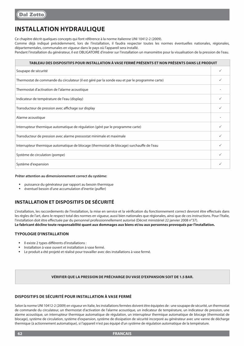
FRANCAIS
INSTALLATION HYDRAULIQUECe chapitre décrit quelques concepts qui font référence à la norme italienne UNI 10412-2 (2009). Comme déjà indiqué précédemment, lors de l’installation, il faudra respecter toutes les normes éventuelles nationales, régionales, départementales, communales en vigueur dans le pays où l’appareil sera installé.Pendant l'installation du générateur, il est OBLIGATOIRE d'insérer sur l'installation un manomètre pour la visualisation de la pression de l'eau.
TABLEAU DES DISPOSITIFS POUR INSTALLATION À VASE FERMÉ PRÉSENTS ET NON PRÉSENTS DANS LE PRODUIT
Soupape de sécurité p
Thermostat de commande du circulateur (il est géré par la sonde eau et par le programme carte) p
Thermostat d'activation de l'alarme acoustique -
Indicateur de température de l'eau (display) p
Transducteur de pression avec a�chage sur display p
Alarme acoustique -
Interrupteur thermique automatique de régulation (géré par le programme carte) p
Transducteur de pression avec alarme pressostat minimale et maximale p
Interrupteur thermique automatique de blocage (thermostat de blocage) surchau�e de l'eau p
Système de circulation (pompe) p
Système d'expansion p
INSTALLATION ET DISPOSITIFS DE SÉCURITÉ
L'installation, les raccordements de l'installation, la mise en service et la véri�cation du fonctionnement correct devront être e�ectués dans les règles de l'art, dans le respect total des normes en vigueur, aussi bien nationales que régionales, ainsi que de ces instructions. Pour l'Italie, l'installation doit être e�ectuée par du personnel professionnellement autorisé (Décret ministériel 22 janvier 2008 n°37).Le fabricant décline toute responsabilité quant aux dommages aux biens et/ou aux personnes provoqués par l'installation.
TYPOLOGIE D'INSTALLATION
� Il existe 2 types di�érents d'installations : � Installation à vase ouvert et installation à vase fermé. � Le produit a été projeté et réalisé pour travailler avec des installations à vase fermé.
DISPOSITIFS DE SÉCURITÉ POUR INSTALLATION À VASE FERMÉ
Selon la norme UNI 10412-2 (2009) en vigueur en Italie, les installations fermées doivent être équipées de : une soupape de sécurité, un thermostat de commande du circulateur, un thermostat d'activation de l'alarme acoustique, un indicateur de température, un indicateur de pression, une alarme acoustique, un interrupteur thermique automatique de régulation, un interrupteur thermique automatique de blocage (thermostat de blocage), système de circulation, système d'expansion, système de dissipation de sécurité incorporé au générateur avec une vanne de décharge thermique (à actionnement automatique), si l'appareil n'est pas équipé d'un système de régulation automatique de la température.
Prêter attention au dimensionnement correct du système:
� puissance du générateur par rapport au besoin thermique � éventuel besoin d'une accumulation d'inertie (pu�er)
VÉRIFIER QUE LA PRESSION DE PRÉCHARGE DU VASE D'EXPANSION SOIT DE 1.5 BAR.
62
FRANCAIS
DISTANCES DES DISPOSITIFS DE SÉCURITÉ CONFORMÉMENT À LA NORMATIVE
Les capteurs de sécurité de la température doivent se trouver sur la machine ou à une distance de 30 cm maximum du raccordement de refoulement. Dans le cas où les générateurs seraient dépourvus de tous les dispositifs, ceux manquants peuvent être installés sur la tuyauterie de refoulement du générateur, à une distance maximale de 1 m. de la machine.
CONTRÔLES AU PREMIER ALLUMAGE
Avant de raccorder la chaudière, prévoir :a) un lavage soigné de toutes les tuyauteries de l'installation a�n d'enlever tout résidu éventuel qui pourrait compromettre le bon fonctionnement de certains composants de l'installation (pompes, vannes, etc.).b) La société suggère vivement d’installer dans le retour du générateur un �ltre magnétique pour augmenter la durée de vie de la chaudière, faciliter l’élimination des impuretés et ampli�er l’e�cacité globale de l’installation.c) un contrôle pour véri�er que la cheminée ait un tirage adéquat, qu'elle n'ait pas d'étranglement et qu'aucune autre évacuation venant d'autres appareils ne soit insérée dans le même tuyau d'évacuation des fumées. Ceci pour éviter des augmentations de puissance non prévues. Uniquement après ce contrôle, il est possible de monter le raccord cheminée entre la chaudière et le tuyau d'évacuation des fumées. Nous conseillons un contrôle des raccords avec les tuyaux d'évacuation des fumées préexistants.
DISPOSITIF ANTI-CONDENSATION (OBLIGATOIRE)
Il est obligatoire de réaliser un circuit anti-condensation adéquat garantissant une température de retour de l'appareil de 55°C au moins. La vanne anti-condensation, par exemple, s'applique aux chaudières thermiques à combustible solide puisqu'elle prévient le retour d'eau froide dans l'échangeur. Une température de retour élevée permet d'améliorer le rendement, réduit la formation de condensation des fumées et prolonge la durée de vie du générateur. Le fabricant conseille d'utiliser le modèle à 55°C avec des raccordements hydrauliques de 1”’. Pour les produits avec contrôle du circulateur PWM, l'installation consiste en la réalisation d'un circuit anti-condensation adapté, dans le cas où:
- le circulateur du générateur de chaleur est unique dans l'installation, ou bien- un échangeur à plaques est intercalé entre le générateur de chaleur et l'installation, ou bien- un compensateur hydraulique ou une accumulation d'inertie (pu�er) est intercalé entre le générateur de chaleur et l'installation
Vanne en vente comme accessoire (option)
63
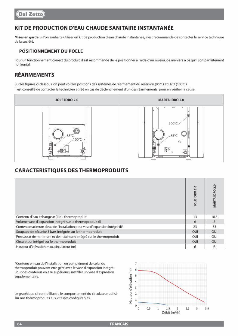
0
1
2
3
4
5
6
7
0 0,5 1 1,5 2 2,5 3 3,5
JOLE IDRO 2.0 MARTA IDRO 2.0
85°C 100°C
85°C 85°C
100°C
100°C
85°C 100°C
85°C 85°C
100°C
100°C
FRANCAIS
KIT DE PRODUCTION D'EAU CHAUDE SANITAIRE INSTANTANÉEMises en garde: si l'on souhaite utiliser un kit de production d'eau chaude instantanée, il est recommandé de contacter le service technique de la société.
POSITIONNEMENT DU POÊLE
Pour un fonctionnement correct du produit, il est recommandé de le positionner à l'aide d'un niveau, de manière à ce qu'il soit parfaitement horizontal.
RÉARMEMENTSSur les �gures ci-dessous, on peut voir les positions des systèmes de réarmement du réservoir (85°C) et H2O (100°C).Il est conseillé de contacter le technicien agréé en cas de déclenchement d'un des réarmements, pour en véri�er la cause.
*Contenu en eau de l'installation en complément de celui du thermoproduit pouvant être géré avec le vase d'expansion intégré. Pour des contenus en eau supérieurs, installer un vase d'expansion supplémentaire.
Le graphique ci-contre illustre le comportement du circulateur utilisé sur nos thermoproduits aux vitesses con�gurables.
Débit (m3/h)
Hau
teur
d'é
léva
tion
(m)
CARACTERISTIQUES DES THERMOPRODUITS
JOLE
IDRO
2.0
MA
RTA
IDRO
2.0
Contenu d'eau échangeur (I) du thermoproduit 13 18.5Volume vase d'expansion intégré sur le thermoproduit (l) 6 8Contenu maximum d'eau de l'installation pour vase d'expansion intégré (I)* 23 33Soupape de sécurité 3 bars intégrée sur le thermoproduit OUI OUIPressostat de minimum et de maximum intégré sur le thermoproduit OUI OUICirculateur intégré sur le thermoproduit OUI OUIHauteur d'élévation max. circulateur (m) 6 6
64
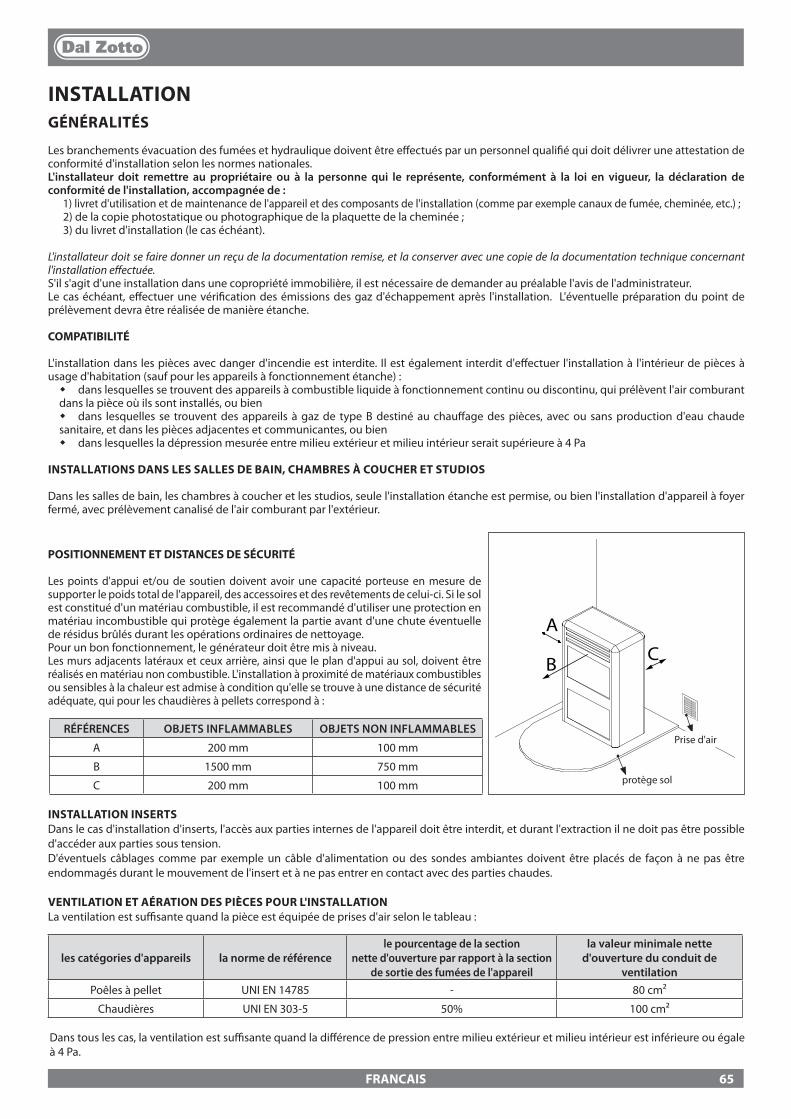
A
CB
FRANCAIS
Prise d'airRÉFÉRENCES OBJETS INFLAMMABLES OBJETS NON INFLAMMABLES
A 200 mm 100 mm
B 1500 mm 750 mm
C 200 mm 100 mm protège sol
INSTALLATION INSERTS Dans le cas d'installation d'inserts, l'accès aux parties internes de l'appareil doit être interdit, et durant l'extraction il ne doit pas être possible d'accéder aux parties sous tension. D'éventuels câblages comme par exemple un câble d'alimentation ou des sondes ambiantes doivent être placés de façon à ne pas être endommagés durant le mouvement de l'insert et à ne pas entrer en contact avec des parties chaudes.
VENTILATION ET AÉRATION DES PIÈCES POUR L'INSTALLATIONLa ventilation est su�sante quand la pièce est équipée de prises d'air selon le tableau :
les catégories d'appareils la norme de référencele pourcentage de la section
nette d'ouverture par rapport à la section de sortie des fumées de l'appareil
la valeur minimale nette d'ouverture du conduit de
ventilationPoêles à pellet UNI EN 14785 - 80 cm²
Chaudières UNI EN 303-5 50% 100 cm²
Dans tous les cas, la ventilation est su�sante quand la di�érence de pression entre milieu extérieur et milieu intérieur est inférieure ou égale à 4 Pa.
INSTALLATIONGÉNÉRALITÉS
Les branchements évacuation des fumées et hydraulique doivent être e�ectués par un personnel quali�é qui doit délivrer une attestation de conformité d'installation selon les normes nationales.L'installateur doit remettre au propriétaire ou à la personne qui le représente, conformément à la loi en vigueur, la déclaration de conformité de l'installation, accompagnée de :
1) livret d'utilisation et de maintenance de l'appareil et des composants de l'installation (comme par exemple canaux de fumée, cheminée, etc.) ;2) de la copie photostatique ou photographique de la plaquette de la cheminée ;3) du livret d'installation (le cas échéant).
L'installateur doit se faire donner un reçu de la documentation remise, et la conserver avec une copie de la documentation technique concernant l'installation e�ectuée.S'il s'agit d'une installation dans une copropriété immobilière, il est nécessaire de demander au préalable l'avis de l'administrateur.Le cas échéant, e�ectuer une véri�cation des émissions des gaz d'échappement après l'installation. L'éventuelle préparation du point de prélèvement devra être réalisée de manière étanche.
COMPATIBILITÉ
L'installation dans les pièces avec danger d'incendie est interdite. Il est également interdit d'e�ectuer l'installation à l'intérieur de pièces à usage d'habitation (sauf pour les appareils à fonctionnement étanche) :
� dans lesquelles se trouvent des appareils à combustible liquide à fonctionnement continu ou discontinu, qui prélèvent l'air comburant dans la pièce où ils sont installés, ou bien
� dans lesquelles se trouvent des appareils à gaz de type B destiné au chau�age des pièces, avec ou sans production d'eau chaude sanitaire, et dans les pièces adjacentes et communicantes, ou bien
� dans lesquelles la dépression mesurée entre milieu extérieur et milieu intérieur serait supérieure à 4 Pa
INSTALLATIONS DANS LES SALLES DE BAIN, CHAMBRES À COUCHER ET STUDIOS
Dans les salles de bain, les chambres à coucher et les studios, seule l'installation étanche est permise, ou bien l'installation d'appareil à foyer fermé, avec prélèvement canalisé de l'air comburant par l'extérieur.
POSITIONNEMENT ET DISTANCES DE SÉCURITÉ
Les points d'appui et/ou de soutien doivent avoir une capacité porteuse en mesure de supporter le poids total de l'appareil, des accessoires et des revêtements de celui-ci. Si le sol est constitué d'un matériau combustible, il est recommandé d'utiliser une protection en matériau incombustible qui protège également la partie avant d'une chute éventuelle de résidus brûlés durant les opérations ordinaires de nettoyage.Pour un bon fonctionnement, le générateur doit être mis à niveau.Les murs adjacents latéraux et ceux arrière, ainsi que le plan d'appui au sol, doivent être réalisés en matériau non combustible. L'installation à proximité de matériaux combustibles ou sensibles à la chaleur est admise à condition qu'elle se trouve à une distance de sécurité adéquate, qui pour les chaudières à pellets correspond à :
65

3 - 5%
Max 3 mt
FRANCAIS
EXEMPLES DE RACCORDEMENT CORRECT À LA CHEMINÉE
En présence d'appareils à gaz de type B à fonctionnement intermittent, non destinés au chau�age, il faut e�ectuer une ouverture d'aération et/ou de ventilation.
Les prises d'air doivent répondre aux exigences suivantes : � être protégées par des grilles, grillages métalliques, etc., sans en réduire la section utile nette ; � être réalisées de façon à rendre possibles les opérations de maintenance ; � être placées de façon à ne pas pouvoir être bouchées ;L'a�ux de l’air propre et non contaminé peut être obtenu aussi d’une pièce adjacente à celle de l’installation (aération et ventilation indirecte), à condition que le �ux puisse se faire librement à travers des ouvertures permanentes en communication avec l’extérieur.La pièce adjacente ne peut pas être utilisée comme garage, stock de matériau combustible ou autres activités comportant un danger d'incendie, salle de bains, chambre à coucher ou pièce commune de l'immeuble.
ÉVACUATION DES FUMÉES
Le générateur de chaleur travaille en dépression et il est muni d'un ventilateur à la sortie pour l'extraction des fumées. Le système d'évacuation doit être unique pour le générateur, des évacuations dans le conduit de la cheminée partagée avec d'autres dispositifs ne sont pas admises. Les composants du système d'évacuation des fumées doivent être choisis par rapport à la typologie de l'appareil à installer conformément à :
� UNI/ TS 11278 dans le cas de cheminées métalliques, avec une attention particulière à ce qui est indiqué dans la désignation ; � UNI EN 13063-1 et UNI EN 13063-2, UNI EN 1457, .-UNI EN 1806 : en cas de cheminées non métalliques. � La longueur de la partie horizontale doit être minime et de toute façon ne pas dépasser 3 mètres, avec une inclinaison minimale de 3%
vers le haut � Le nombre de changements de direction, y compris dû à l'utilisation d'un élément en "T", doit se limiter à 4 . � Il faut prévoir un raccord en "T" avec un bouchon de récolte des condensats à la base de la partie verticale. � Si l'évacuation ne s'insère pas dans un conduit de cheminée, une partie verticale avec un terminal anti-vent est demandée (UNI 10683) � Le conduit vertical peut être à l'intérieur ou à l'extérieur de l'édi�ce. Si le canal à fumée s'insère dans un conduit de cheminée existant
déjà, celui-ci doit être certi�é pour combustibles solides � Si le canal à fumée est à l'extérieur de l'édi�ce, il doit toujours être isolé. � Les canaux à fumée doivent être prévus avec au moins une prise étanche pour d'éventuels échantillonnages de fumées. � Toutes les parties du conduit des fumées doivent pouvoir être inspectées. � Des ouvertures d'inspection doivent être prévues pour le nettoyage. � Si la température des fumées du générateur est inférieure à 160°C+ température ambiante à cause du haut rendement (consulter
données techniques), le générateur devra absolument être résistant à l'humidité.
POT DE CHEMINÉE
Les pots de cheminée doivent répondre aux exigences suivantes : � avoir une section utile de sortie non inférieure au double de celle de la cheminée/système tubé sur lequel il est inséré ; � être conformés de façon à empêcher la pénétration dans la cheminée/système tubé de la pluie et de la neige ; � être construits de façon à garantir l'évacuation des produits de la combustion, même en cas de vents provenant de n'importe quelle
direction et avec n'importe quelle inclinaison ;
Protection contre la pluie et le vent
Raccord en T anti-condensation avec bouchon d'inspection
Conduit de cheminée isolé
Raccord en T isolé avec bouchon d'inspection
Protection contre la pluie et le vent
Raccord en T avec bouchon d'inspection
BRANCHEMENT AU RÉSEAU ÉLECTRIQUE Le générateur est muni d'un câble d'alimentation électrique qui doit être branché à une prise de 230V 50Hz, avec, si possible, un interrupteur magnétothermique. La prise de courant doit être facilement accessible.L'installation électrique doit être conformes aux normes ; véri�er en particulier l'e�cacité du circuit de mise à la terre. Une mise à la terre non adéquate de l'installation peut provoquer un dysfonctionnement dont le fabricant ne se retient pas responsable. Des variations d'alimentation supérieures à 10% peuvent provoquer des anomalies de fonctionnement du produit.
66
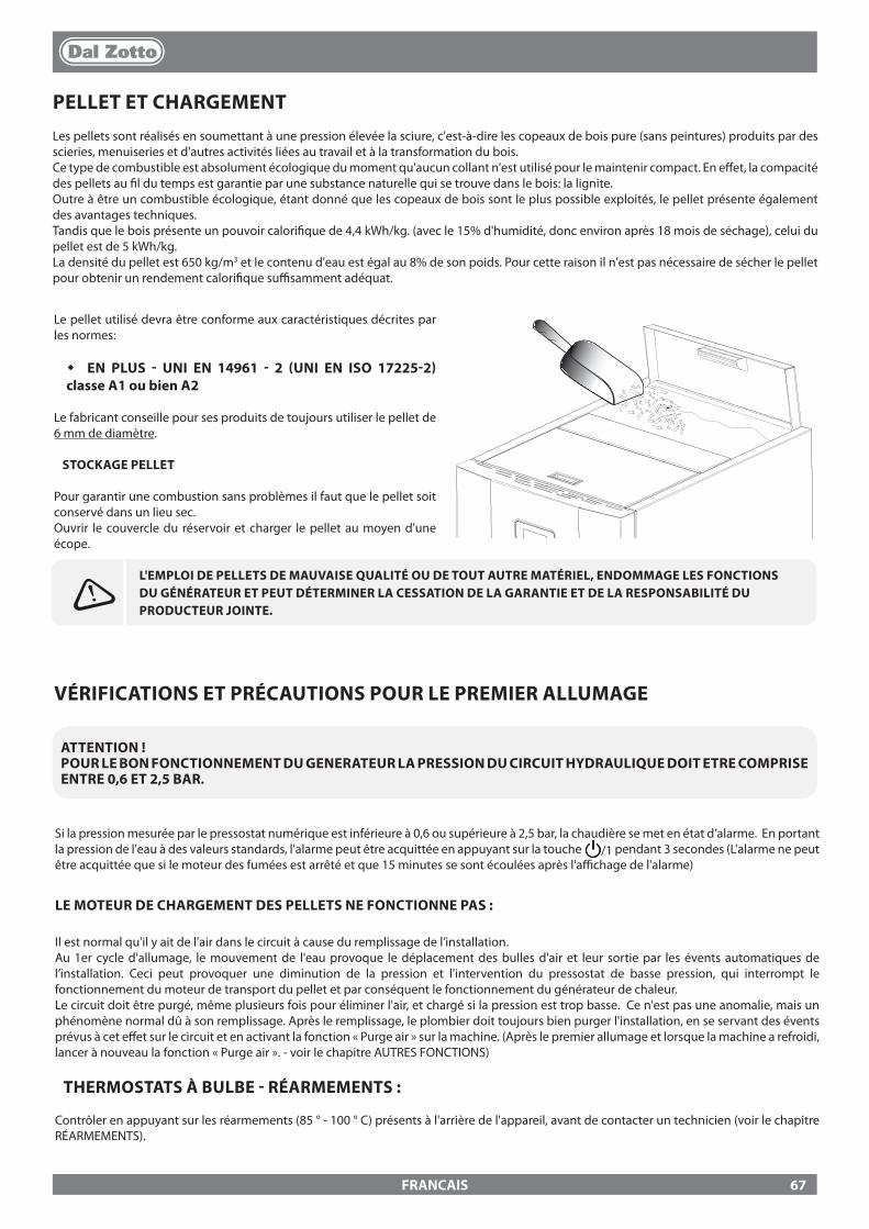
FRANCAIS
PELLET ET CHARGEMENTLes pellets sont réalisés en soumettant à une pression élevée la sciure, c'est-à-dire les copeaux de bois pure (sans peintures) produits par des scieries, menuiseries et d'autres activités liées au travail et à la transformation du bois.Ce type de combustible est absolument écologique du moment qu'aucun collant n'est utilisé pour le maintenir compact. En e�et, la compacité des pellets au �l du temps est garantie par une substance naturelle qui se trouve dans le bois: la lignite.Outre à être un combustible écologique, étant donné que les copeaux de bois sont le plus possible exploités, le pellet présente également des avantages techniques.Tandis que le bois présente un pouvoir calori�que de 4,4 kWh/kg. (avec le 15% d'humidité, donc environ après 18 mois de séchage), celui du pellet est de 5 kWh/kg.La densité du pellet est 650 kg/m3 et le contenu d'eau est égal au 8% de son poids. Pour cette raison il n'est pas nécessaire de sécher le pellet pour obtenir un rendement calori�que su�samment adéquat.
L'EMPLOI DE PELLETS DE MAUVAISE QUALITÉ OU DE TOUT AUTRE MATÉRIEL, ENDOMMAGE LES FONCTIONS DU GÉNÉRATEUR ET PEUT DÉTERMINER LA CESSATION DE LA GARANTIE ET DE LA RESPONSABILITÉ DU PRODUCTEUR JOINTE.
Le pellet utilisé devra être conforme aux caractéristiques décrites par les normes:
� EN PLUS - UNI EN 14961 - 2 (UNI EN ISO 17225-2) classe A1 ou bien A2
Le fabricant conseille pour ses produits de toujours utiliser le pellet de 6 mm de diamètre.
STOCKAGE PELLET
Pour garantir une combustion sans problèmes il faut que le pellet soit conservé dans un lieu sec.Ouvrir le couvercle du réservoir et charger le pellet au moyen d'une écope.
VÉRIFICATIONS ET PRÉCAUTIONS POUR LE PREMIER ALLUMAGE
ATTENTION !POUR LE BON FONCTIONNEMENT DU GENERATEUR LA PRESSION DU CIRCUIT HYDRAULIQUE DOIT ETRE COMPRISE ENTRE 0,6 ET 2,5 BAR.
Si la pression mesurée par le pressostat numérique est inférieure à 0,6 ou supérieure à 2,5 bar, la chaudière se met en état d’alarme. En portant la pression de l'eau à des valeurs standards, l'alarme peut être acquittée en appuyant sur la touche /1 pendant 3 secondes (L'alarme ne peut être acquittée que si le moteur des fumées est arrêté et que 15 minutes se sont écoulées après l'a�chage de l'alarme)
LE MOTEUR DE CHARGEMENT DES PELLETS NE FONCTIONNE PAS :
Il est normal qu'il y ait de l'air dans le circuit à cause du remplissage de l’installation.Au 1er cycle d'allumage, le mouvement de l'eau provoque le déplacement des bulles d'air et leur sortie par les évents automatiques de l’installation. Ceci peut provoquer une diminution de la pression et l'intervention du pressostat de basse pression, qui interrompt le fonctionnement du moteur de transport du pellet et par conséquent le fonctionnement du générateur de chaleur.Le circuit doit être purgé, même plusieurs fois pour éliminer l'air, et chargé si la pression est trop basse. Ce n'est pas une anomalie, mais un phénomène normal dû à son remplissage. Après le remplissage, le plombier doit toujours bien purger l'installation, en se servant des évents prévus à cet e�et sur le circuit et en activant la fonction « Purge air » sur la machine. (Après le premier allumage et lorsque la machine a refroidi, lancer à nouveau la fonction « Purge air ». - voir le chapitre AUTRES FONCTIONS)
THERMOSTATS À BULBE - RÉARMEMENTS :
Contrôler en appuyant sur les réarmements (85 ° - 100 ° C) présents à l'arrière de l'appareil, avant de contacter un technicien (voir le chapitre RÉARMEMENTS).
67
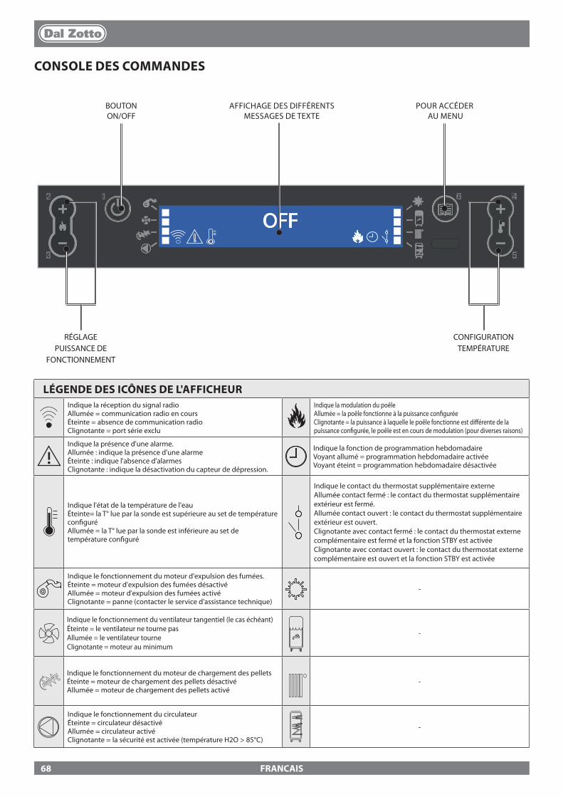
12
3
4
5
6
OFF
FRANCAIS
CONSOLE DES COMMANDES
BOUTON ON/OFF
AFFICHAGE DES DIFFÉRENTS MESSAGES DE TEXTE
POUR ACCÉDER AU MENU
CONFIGURATION TEMPÉRATURE
RÉGLAGE PUISSANCE DE
FONCTIONNEMENT
LÉGENDE DES ICÔNES DE L'AFFICHEURIndique la réception du signal radioAllumée = communication radio en coursÉteinte = absence de communication radioClignotante = port série exclu
Indique la modulation du poêleAllumée = la poêle fonctionne à la puissance con�guréeClignotante = la puissance à laquelle le poêle fonctionne est di�érente de la puissance con�gurée, le poêle est en cours de modulation (pour diverses raisons)
Indique la présence d'une alarme.Allumée : indique la présence d'une alarmeÉteinte : indique l'absence d'alarmesClignotante : indique la désactivation du capteur de dépression.
Indique la fonction de programmation hebdomadaireVoyant allumé = programmation hebdomadaire activéeVoyant éteint = programmation hebdomadaire désactivée
Indique l'état de la température de l'eauÉteinte= la T° lue par la sonde est supérieure au set de température con�guréAllumée = la T° lue par la sonde est inférieure au set de température con�guré
Indique le contact du thermostat supplémentaire externeAllumée contact fermé : le contact du thermostat supplémentaire extérieur est fermé.Allumée contact ouvert : le contact du thermostat supplémentaire extérieur est ouvert.Clignotante avec contact fermé : le contact du thermostat externe complémentaire est fermé et la fonction STBY est activéeClignotante avec contact ouvert : le contact du thermostat externe complémentaire est ouvert et la fonction STBY est activée
Indique le fonctionnement du moteur d'expulsion des fumées.Éteinte = moteur d'expulsion des fumées désactivéAllumée = moteur d'expulsion des fumées activéClignotante = panne (contacter le service d'assistance technique)
-
Indique le fonctionnement du ventilateur tangentiel (le cas échéant)Éteinte = le ventilateur ne tourne pasAllumée = le ventilateur tourneClignotante = moteur au minimum
-
Indique le fonctionnement du moteur de chargement des pelletsÉteinte = moteur de chargement des pellets désactivéAllumée = moteur de chargement des pellets activé
-
Indique le fonctionnement du circulateurÉteinte = circulateur désactivéAllumée = circulateur activéClignotante = la sécurité est activée (température H2O > 85°C)
-
68

OFF12
3
4
5
6
1
2 3
4 5
6
12
3
46
5
6
FRANCAIS
MENU GÉNÉRALRetour en arrière - quitter
Dé�lement des paramètres : suivant (2) ; précédent (3)
Modi�cation des données de con�guration : augmentation (4) ; diminution (5)
Con�rmation - accès au Menu
SET PUISSANCE PUISSANCE
SET TEMPÉRATURES SET TEMPÉRATURE AMBIANTE
SET H2O
MENU UTILISATEUR *HABILITER V1
* V1 AIR
SET CHRONO HABILITATION DU CHRONO EFFACER
HABILITER PRG1 EASY SET UP
HABILITER PRG2
ÉTAT **ÉTAT DU POÊLE HABILITER PRG3
HABILITER PRG4
REGLAGES SET HORLOGE START PRG1
LANGUE STOP PRG1
DISPLAY LUNDI PRG1...
STAND-BY ...DIMANCHE PRG1
** MENUTECHNIQUE
SET PRG1 * LE CAS ÉCHÉANT
** RÉSERVÉ AU TECHNICIENMÊMES PASSAGES POUR LES AUTRES 3 TRANCHES HORAIRES
L'entreprise dispose d'une carte supplémentaire en option qui permet à la chaudière de réaliser les fonctions supplémentaires suivantes dans la gestion de l'installation. Dans le tableau suivant, sont indiquées les di�érentes possibilités que l'option peut o�rir.
Gestion Accumulateur sanitaire pGestion Pu�er p3 zones de chau�age pOption eau sanitaire instantanée pGestion pompe pu�er ou 4ème zone de chau�age pGestion antilégionellose pour accumulation accumulateur sanitaire pGestion chrono accumulateur sanitaire pGestion et contrôle sortie auxiliaire p
INSTRUCTIONS DE BASE
� Pendant les premiers allumages du poêle, il faut prêter attention aux conseils suivants :� Il est possible que de légères odeurs se produisent suite au séchage des vernis et des silicones utilisés. Éviter toute permanence prolongée dans l'environnement.� Ne pas toucher les surfaces car elles pourraient encore être instables.� Bien aérer le local plusieurs fois.� Le durcissement des surfaces s'achève après quelques chau�ages.� Cet appareil ne doit pas être utilisé comme incinérateur de déchets.
� Avant d'allumer le poêle, il faut véri�er les points suivants :� Le circuit hydraulique doit être terminé, respecter les indications des normes et du manuel.� Le réservoir doit être rempli de pellets.� La chambre de combustion doit être propre.� Le brasier doit être complètement libre et propre.� Véri�er la fermeture hermétique de la porte feu et du tiroir à cendres.� Véri�er que le câble d'alimentation soit connecté correctement.� L'interrupteur bipolaire situé dans la partie arrière droite doit être en position 1.
69
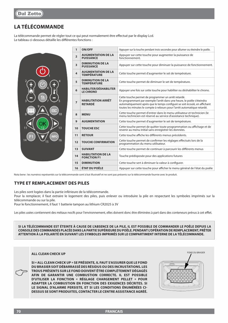
FRANCAIS
LA TÉLÉCOMMANDELa télécommande permet de régler tout ce qui peut normalement être e�ectué par le display Lcd.Le tableau ci-dessous détaille les di�érentes fonctions :
INFO
1
2
3
4
5
6
7
8
9
10
11 12 13
14 15 16
1 ON/OFF Appuyer sur la touche pendant trois secondes pour allumer ou éteindre le poêle.
2 AUGMENTATION DE LA PUISSANCE
Appuyer sur cette touche pour augmenter la puissance de fonctionnement.
3 DIMINUTION DE LA PUISSANCE Appuyer sur cette touche pour diminuer la puissance de fonctionnement.
4 AUGMENTATION DE LA TEMPÉRATURE Cette touche permet d'augmenter le set de température.
5 DIMINUTION DE LA TEMPÉRATURE Cette touche permet de diminuer le set de température.
6 HABILITER/DÉSHABILITER LE CHRONO Appuyer une fois sur cette touche pour habiliter ou déshabiliter le chrono.
7 HABILITATION ARRÊT RETARDÉ
Cette touche permet de programmer un arrêt retardé. En programmant par exemple l'arrêt dans une heure, le poêle s'éteindra automatiquement après que le temps con�guré se soit écoulé, en a�chant toutes les minutes le compte à rebours pour l'arrêt automatique retardé.
8 MENU Cette touche permet d'entrer dans le menu utilisateur et technicien (le menu technicien est réservé au service d'assistance technique).
9 AUGMENTATION Cette touche permet d'augmenter le set de température.
10 TOUCHE ESC Cette touche permet de quitter toute programmation ou a�chage et de revenir au menu initial sans enregistrer les données.
11 RETOUR Cette touche a�che les di�érents menus précédents.
12 TOUCHE CONFIRMATION Cette touche permet de con�rmer les réglages e�ectués lors de la programmation du menu utilisateur.
13 SUIVANT Cette touche permet de continuer à parcourir les di�érents menus
14 HABILITATION DE LA FONCTION F1 Touche prédisposée pour des applications futures
15 DIMINUTION Cette touche sert à diminuer la valeur à con�gurer.
16 ÉTAT DU POÊLE Appuyer sur cette touche pour a�cher le menu général de l'état du poêle
TYPE ET REMPLACEMENT DES PILES
Les piles sont logées dans la partie inférieure de la télécommande. Pour la remplacer, il faut extraire le logement des piles, puis enlever ou introduire la pile en respectant les symboles imprimés sur la télécommande ou sur la pile.Pour le fonctionnement, il faut 1 batterie tampon au lithium CR2025 à 3V
Les piles usées contiennent des métaux nocifs pour l'environnement, elles doivent donc être éliminées à part dans des conteneurs prévus à cet e�et.
Nota bene : les numéros représentés sur la télécommande sont à but illustratif et ne sont pas présents sur la télécommande fournie avec le produit.
SI LA TÉLÉCOMMANDE EST ÉTEINTE À CAUSE DE L'ABSENCE DE LA PILE, IL EST POSSIBLE DE COMMANDER LE POÊLE DEPUIS LA CONSOLE DES COMMANDES PLACÉE DANS LA PARTIE SUPÉRIEURE DU POÊLE. PENDANT L'OPÉRATION DE REMPLACEMENT, PRÊTER ATTENTION À LA POLARITÉ EN SUIVANT LES SYMBOLES IMPRIMÉS SUR LE COMPARTIMENT INTERNE DE LA TÉLÉCOMMANDE.
J
ALL CLEAN CHECK UP
SI « ALL CLEAN CHECK UP » SE PRÉSENTE, IL FAUT S'ASSURER QUE LE FOND DU BRASIER SOIT DÉBARRASSÉ DES RÉSIDUS OU DES INCRUSTATIONS. LES TROUS PRÉSENTS SUR LE FOND DOIVENT ÊTRE COMPLÈTEMENT DÉGAGÉS AFIN DE GARANTIR UNE COMBUSTION CORRECTE. IL EST POSSIBLE D'UTILISER LA FONCTION « RÉGLAGE CHARGEMENT PELLET » POUR ADAPTER LA COMBUSTION EN FONCTION DES EXIGENCES DÉCRITES. SI LE SIGNAL D'ALARME PERSISTE, ET SI LES CONDITIONS ÉNUMÉRÉES CI-DESSUS SE SONT PRODUITES, CONTACTER LE CENTRE ASSISTANCE AGRÉÉ.
FOND DU BRASIER
70
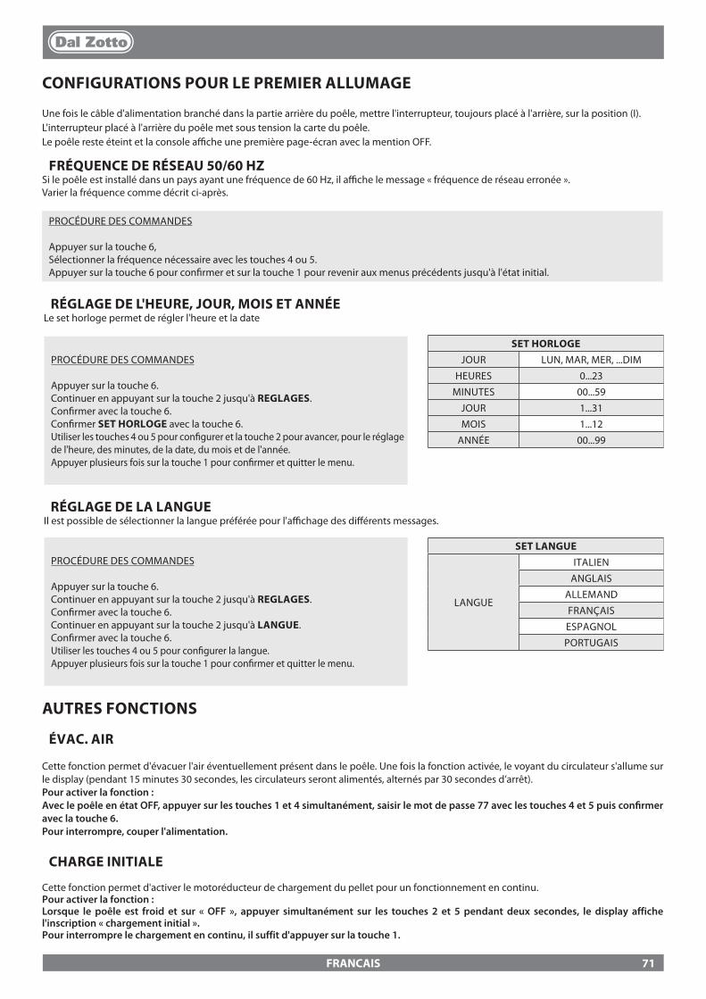
FRANCAIS
RÉGLAGE DE L'HEURE, JOUR, MOIS ET ANNÉELe set horloge permet de régler l'heure et la date
PROCÉDURE DES COMMANDES
Appuyer sur la touche 6.Continuer en appuyant sur la touche 2 jusqu'à REGLAGES.Con�rmer avec la touche 6.Continuer en appuyant sur la touche 2 jusqu'à LANGUE.Con�rmer avec la touche 6.Utiliser les touches 4 ou 5 pour con�gurer la langue.Appuyer plusieurs fois sur la touche 1 pour con�rmer et quitter le menu.
SET LANGUE
LANGUE
ITALIEN
ANGLAIS
ALLEMAND
FRANÇAIS
ESPAGNOL
PORTUGAIS
CONFIGURATIONS POUR LE PREMIER ALLUMAGE
Une fois le câble d'alimentation branché dans la partie arrière du poêle, mettre l'interrupteur, toujours placé à l'arrière, sur la position (I).L'interrupteur placé à l'arrière du poêle met sous tension la carte du poêle.Le poêle reste éteint et la console a�che une première page-écran avec la mention OFF.
AUTRES FONCTIONS
ÉVAC. AIR
Cette fonction permet d'évacuer l'air éventuellement présent dans le poêle. Une fois la fonction activée, le voyant du circulateur s'allume sur le display (pendant 15 minutes 30 secondes, les circulateurs seront alimentés, alternés par 30 secondes d’arrêt).Pour activer la fonction :Avec le poêle en état OFF, appuyer sur les touches 1 et 4 simultanément, saisir le mot de passe 77 avec les touches 4 et 5 puis con�rmer avec la touche 6. Pour interrompre, couper l'alimentation.
CHARGE INITIALE
Cette fonction permet d'activer le motoréducteur de chargement du pellet pour un fonctionnement en continu. Pour activer la fonction :Lorsque le poêle est froid et sur « OFF », appuyer simultanément sur les touches 2 et 5 pendant deux secondes, le display affiche l'inscription « chargement initial ».Pour interrompre le chargement en continu, il suffit d'appuyer sur la touche 1.
PROCÉDURE DES COMMANDES
Appuyer sur la touche 6.Continuer en appuyant sur la touche 2 jusqu'à REGLAGES.Con�rmer avec la touche 6.Con�rmer SET HORLOGE avec la touche 6.Utiliser les touches 4 ou 5 pour con�gurer et la touche 2 pour avancer, pour le réglage de l'heure, des minutes, de la date, du mois et de l'année.Appuyer plusieurs fois sur la touche 1 pour con�rmer et quitter le menu.
SET HORLOGEJOUR LUN, MAR, MER, ...DIM
HEURES 0...23
MINUTES 00...59
JOUR 1...31
MOIS 1...12
ANNÉE 00...99
RÉGLAGE DE LA LANGUEIl est possible de sélectionner la langue préférée pour l'a�chage des di�érents messages.
FRÉQUENCE DE RÉSEAU 50/60 HZSi le poêle est installé dans un pays ayant une fréquence de 60 Hz, il a�che le message « fréquence de réseau erronée ».Varier la fréquence comme décrit ci-après.
PROCÉDURE DES COMMANDES
Appuyer sur la touche 6, Sélectionner la fréquence nécessaire avec les touches 4 ou 5.Appuyer sur la touche 6 pour con�rmer et sur la touche 1 pour revenir aux menus précédents jusqu'à l'état initial.
71
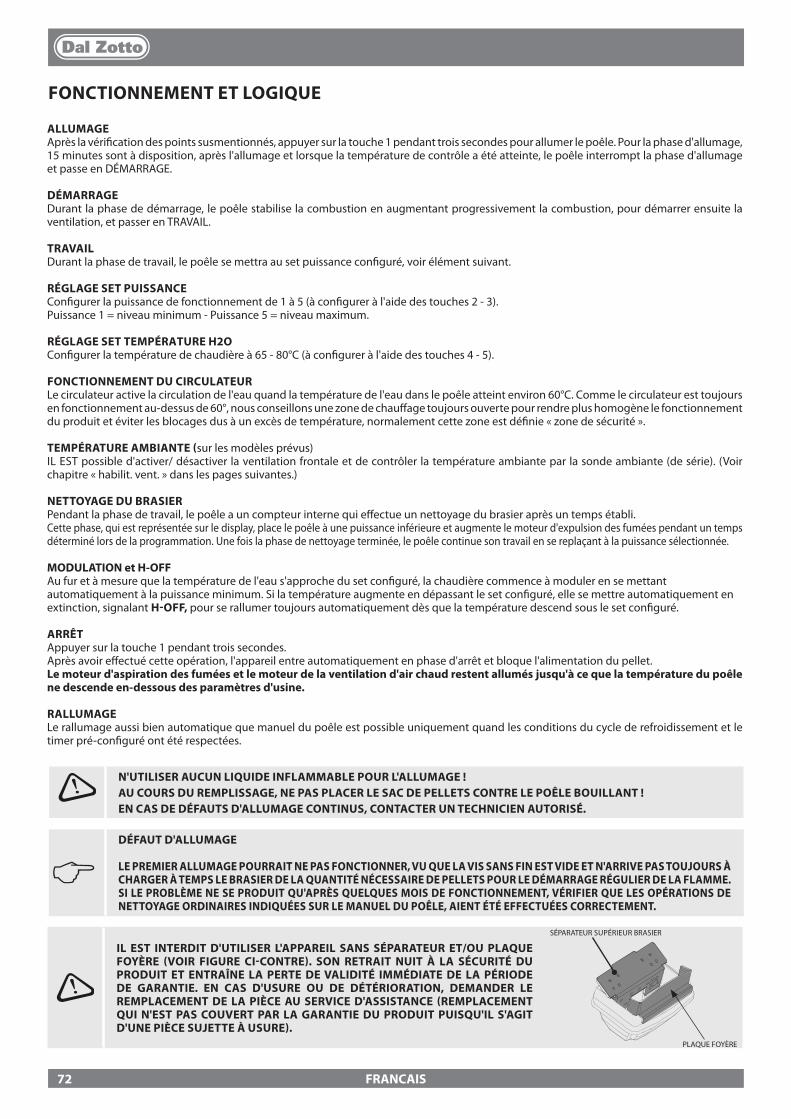
FRANCAIS
FONCTIONNEMENT ET LOGIQUE
ALLUMAGEAprès la véri�cation des points susmentionnés, appuyer sur la touche 1 pendant trois secondes pour allumer le poêle. Pour la phase d'allumage, 15 minutes sont à disposition, après l'allumage et lorsque la température de contrôle a été atteinte, le poêle interrompt la phase d'allumage et passe en DÉMARRAGE.
DÉMARRAGEDurant la phase de démarrage, le poêle stabilise la combustion en augmentant progressivement la combustion, pour démarrer ensuite la ventilation, et passer en TRAVAIL.
TRAVAILDurant la phase de travail, le poêle se mettra au set puissance con�guré, voir élément suivant.
RÉGLAGE SET PUISSANCECon�gurer la puissance de fonctionnement de 1 à 5 (à con�gurer à l'aide des touches 2 - 3).Puissance 1 = niveau minimum - Puissance 5 = niveau maximum.
RÉGLAGE SET TEMPÉRATURE H2OCon�gurer la température de chaudière à 65 - 80°C (à con�gurer à l'aide des touches 4 - 5).
FONCTIONNEMENT DU CIRCULATEURLe circulateur active la circulation de l'eau quand la température de l'eau dans le poêle atteint environ 60°C. Comme le circulateur est toujours en fonctionnement au-dessus de 60°, nous conseillons une zone de chau�age toujours ouverte pour rendre plus homogène le fonctionnement du produit et éviter les blocages dus à un excès de température, normalement cette zone est dé�nie « zone de sécurité ».
TEMPÉRATURE AMBIANTE (sur les modèles prévus)IL EST possible d'activer/ désactiver la ventilation frontale et de contrôler la température ambiante par la sonde ambiante (de série). (Voir chapitre « habilit. vent. » dans les pages suivantes.)
NETTOYAGE DU BRASIERPendant la phase de travail, le poêle a un compteur interne qui e�ectue un nettoyage du brasier après un temps établi.Cette phase, qui est représentée sur le display, place le poêle à une puissance inférieure et augmente le moteur d'expulsion des fumées pendant un temps déterminé lors de la programmation. Une fois la phase de nettoyage terminée, le poêle continue son travail en se replaçant à la puissance sélectionnée.
MODULATION et H-OFFAu fur et à mesure que la température de l'eau s'approche du set con�guré, la chaudière commence à moduler en se mettant automatiquement à la puissance minimum. Si la température augmente en dépassant le set con�guré, elle se mettre automatiquement en extinction, signalant H-OFF, pour se rallumer toujours automatiquement dès que la température descend sous le set con�guré.
ARRÊTAppuyer sur la touche 1 pendant trois secondes.Après avoir e�ectué cette opération, l'appareil entre automatiquement en phase d'arrêt et bloque l'alimentation du pellet.Le moteur d'aspiration des fumées et le moteur de la ventilation d'air chaud restent allumés jusqu'à ce que la température du poêle ne descende en-dessous des paramètres d'usine.
RALLUMAGELe rallumage aussi bien automatique que manuel du poêle est possible uniquement quand les conditions du cycle de refroidissement et le timer pré-con�guré ont été respectées.
J DÉFAUT D'ALLUMAGE
LE PREMIER ALLUMAGE POURRAIT NE PAS FONCTIONNER, VU QUE LA VIS SANS FIN EST VIDE ET N'ARRIVE PAS TOUJOURS À CHARGER À TEMPS LE BRASIER DE LA QUANTITÉ NÉCESSAIRE DE PELLETS POUR LE DÉMARRAGE RÉGULIER DE LA FLAMME. SI LE PROBLÈME NE SE PRODUIT QU'APRÈS QUELQUES MOIS DE FONCTIONNEMENT, VÉRIFIER QUE LES OPÉRATIONS DE NETTOYAGE ORDINAIRES INDIQUÉES SUR LE MANUEL DU POÊLE, AIENT ÉTÉ EFFECTUÉES CORRECTEMENT.
N'UTILISER AUCUN LIQUIDE INFLAMMABLE POUR L'ALLUMAGE !AU COURS DU REMPLISSAGE, NE PAS PLACER LE SAC DE PELLETS CONTRE LE POÊLE BOUILLANT !EN CAS DE DÉFAUTS D'ALLUMAGE CONTINUS, CONTACTER UN TECHNICIEN AUTORISÉ.
IL EST INTERDIT D'UTILISER L'APPAREIL SANS SÉPARATEUR ET/OU PLAQUE FOYÈRE (VOIR FIGURE CI-CONTRE). SON RETRAIT NUIT À LA SÉCURITÉ DU PRODUIT ET ENTRAÎNE LA PERTE DE VALIDITÉ IMMÉDIATE DE LA PÉRIODE DE GARANTIE. EN CAS D'USURE OU DE DÉTÉRIORATION, DEMANDER LE REMPLACEMENT DE LA PIÈCE AU SERVICE D'ASSISTANCE (REMPLACEMENT QUI N'EST PAS COUVERT PAR LA GARANTIE DU PRODUIT PUISQU'IL S'AGIT D'UNE PIÈCE SUJETTE À USURE).
SÉPARATEUR SUPÉRIEUR BRASIER
PLAQUE FOYÈRE
72

JOLE IDRO 2.0 MARTA IDRO 2.0
FRANCAIS
THERMOSTAT SUPPLÉMENTAIRE
N.B. : L'installation doit être e�ectuée par un technicien autorisé
Il existe la possibilité de thermostater un local adjacent à la pièce où se trouve le poêle : il su�t de connecter un thermostat mécanique en suivant la procédure décrite au point suivant (nous conseillons de placer le thermostat mécanique en option à une hauteur du sol de 1,50 m). Le fonctionnement du poêle avec le thermostat externe connecté à la borne TA peut être di�érent en fonction de l'activation ou de la désactivation de la fonction STBY.La borne TA sort pontée de l'usine et se présente donc toujours avec un contact fermé (en demande).
FONCTIONNEMENT DU THERMOSTAT SUPPLÉMENTAIRE AVEC STBY ACTIVÉLorsque la fonction STBY est activée, la LED clignote. Quand le contact ou le thermostat externe est satisfait (contact ouvert / température atteinte), le poêle s'éteint. Dès que le contact ou que le thermostat externe passe en état « insatisfait » (contact fermé / température à atteindre), il se rallume.Nota bene : le fonctionnement du poêle dépend de la température de l'eau à l'intérieur du poêle et des relatives con�gurations d'usine. Si le poêle est en H OFF (température de l'eau atteinte), la demande éventuelle du contact ou du thermostat supplémentaire est ignorée.
FONCTIONNEMENT DU THERMOSTAT SUPPLÉMENTAIRE AVEC STBY DÉSACTIVÉLorsque la fonction STBY est désactivée, la LED est �xe.Quand le contact ou le thermostat externe est satisfait (contact ouvert / température atteinte), le poêle se met au minimum. Dès que le contact ou que le thermostat externe passe en état « insatisfait » (contact fermé / température à atteindre), la poêle recommence à fonctionner à la puissance pré-con�gurée. Nota bene : le fonctionnement du poêle dépend de la température de l'eau à l'intérieur du poêle et des relatives con�gurations d'usine. Si le poêle est en H OFF (température de l'eau atteinte), la demande éventuelle du contact ou du thermostat supplémentaire est ignorée.
INSTALLATION DU THERMOSTAT SUPPLÉMENTAIRE� Éteindre l'appareil au moyen de l'interrupteur général situé à l'arrière du poêle.� Retirer la �che de la prise de courant.� En se basant sur le schéma électrique, connecter les deux câbles du thermostat aux bornes correspondantes situées à l'arrière de la machine, l'un de couleur rouge et l'autre noire (borne TA). Chaque modèle peut posséder une position di�érente des bornes à l'arrière de la machine. L'image n'est fournie qu'à titre d'exemple.
J
POUR L'ACTIVATION DU STAND BY, CONSULTER LE CHAPITRE « CONFIGURATIONS »
73
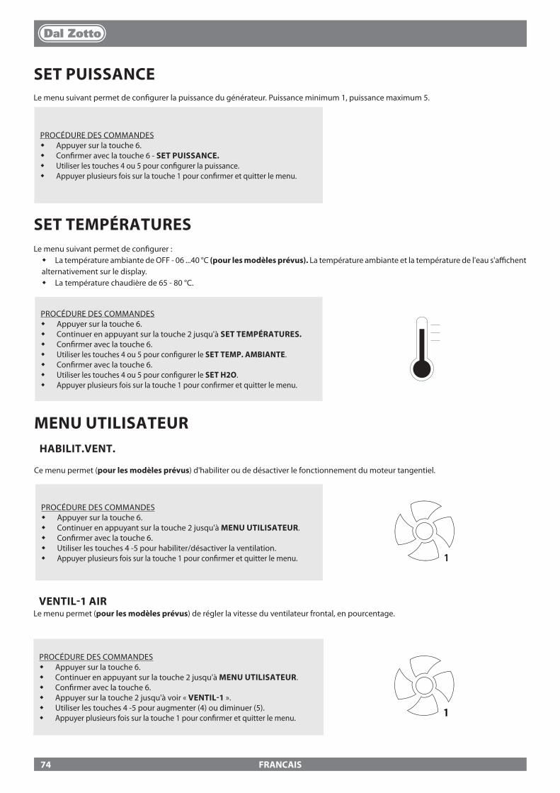
FRANCAIS
SET PUISSANCELe menu suivant permet de con�gurer la puissance du générateur. Puissance minimum 1, puissance maximum 5.
PROCÉDURE DES COMMANDES� Appuyer sur la touche 6.� Con�rmer avec la touche 6 - SET PUISSANCE.� Utiliser les touches 4 ou 5 pour con�gurer la puissance.� Appuyer plusieurs fois sur la touche 1 pour con�rmer et quitter le menu.
SET TEMPÉRATURESLe menu suivant permet de con�gurer :� La température ambiante de OFF - 06 ...40 °C (pour les modèles prévus). La température ambiante et la température de l'eau s'a�chent alternativement sur le display.� La température chaudière de 65 - 80 °C.
PROCÉDURE DES COMMANDES� Appuyer sur la touche 6.� Continuer en appuyant sur la touche 2 jusqu'à SET TEMPÉRATURES.� Con�rmer avec la touche 6.� Utiliser les touches 4 ou 5 pour con�gurer le SET TEMP. AMBIANTE.� Con�rmer avec la touche 6.� Utiliser les touches 4 ou 5 pour con�gurer le SET H2O.� Appuyer plusieurs fois sur la touche 1 pour con�rmer et quitter le menu.
MENU UTILISATEURHABILIT.VENT.
Ce menu permet (pour les modèles prévus) d'habiliter ou de désactiver le fonctionnement du moteur tangentiel.
PROCÉDURE DES COMMANDES� Appuyer sur la touche 6.� Continuer en appuyant sur la touche 2 jusqu'à MENU UTILISATEUR.� Con�rmer avec la touche 6.� Utiliser les touches 4 -5 pour habiliter/désactiver la ventilation. � Appuyer plusieurs fois sur la touche 1 pour con�rmer et quitter le menu. 1
VENTIL-1 AIRLe menu permet (pour les modèles prévus) de régler la vitesse du ventilateur frontal, en pourcentage.
PROCÉDURE DES COMMANDES� Appuyer sur la touche 6.� Continuer en appuyant sur la touche 2 jusqu'à MENU UTILISATEUR.� Con�rmer avec la touche 6.� Appuyer sur la touche 2 jusqu'à voir « VENTIL-1 ».� Utiliser les touches 4 -5 pour augmenter (4) ou diminuer (5).� Appuyer plusieurs fois sur la touche 1 pour con�rmer et quitter le menu. 1
74
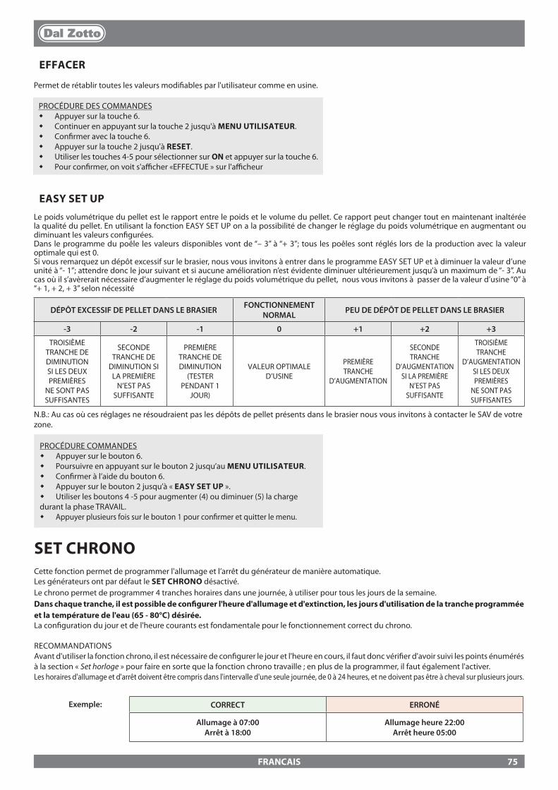
FRANCAIS
PROCÉDURE DES COMMANDES� Appuyer sur la touche 6.� Continuer en appuyant sur la touche 2 jusqu'à MENU UTILISATEUR.� Con�rmer avec la touche 6.� Appuyer sur la touche 2 jusqu'à RESET.� Utiliser les touches 4-5 pour sélectionner sur ON et appuyer sur la touche 6.� Pour con�rmer, on voit s'a�cher «EFFECTUE » sur l'a�cheur
EASY SET UPLe poids volumétrique du pellet est le rapport entre le poids et le volume du pellet. Ce rapport peut changer tout en maintenant inaltérée la qualité du pellet. En utilisant la fonction EASY SET UP on a la possibilité de changer le réglage du poids volumétrique en augmentant ou diminuant les valeurs con�gurées.Dans le programme du poêle les valeurs disponibles vont de “– 3” à “+ 3”; tous les poêles sont réglés lors de la production avec la valeur optimale qui est 0.Si vous remarquez un dépôt excessif sur le brasier, nous vous invitons à entrer dans le programme EASY SET UP et à diminuer la valeur d’une unité à “- 1”; attendre donc le jour suivant et si aucune amélioration n’est évidente diminuer ultérieurement jusqu’à un maximum de “- 3”. Au cas où il s’avèrerait nécessaire d’augmenter le réglage du poids volumétrique du pellet, nous vous invitons à passer de la valeur d’usine “0” à “+ 1, + 2, + 3” selon nécessité
EFFACER
Permet de rétablir toutes les valeurs modi�ables par l'utilisateur comme en usine.
DÉPÔT EXCESSIF DE PELLET DANS LE BRASIER FONCTIONNEMENT NORMAL PEU DE DÉPÔT DE PELLET DANS LE BRASIER
-3 -2 -1 0 +1 +2 +3
TROISIÈME TRANCHE DE DIMINUTION SI LES DEUX PREMIÈRES
NE SONT PAS SUFFISANTES
SECONDE TRANCHE DE
DIMINUTION SI LA PREMIÈRE
N’EST PAS SUFFISANTE
PREMIÈRE TRANCHE DE DIMINUTION
(TESTER PENDANT 1
JOUR)
VALEUR OPTIMALE D’USINE
PREMIÈRE TRANCHE
D’AUGMENTATION
SECONDE TRANCHE
D’AUGMENTATION SI LA PREMIÈRE
N’EST PAS SUFFISANTE
TROISIÈME TRANCHE
D’AUGMENTATION SI LES DEUX PREMIÈRES
NE SONT PAS SUFFISANTES
SET CHRONOCette fonction permet de programmer l'allumage et l’arrêt du générateur de manière automatique.Les générateurs ont par défaut le SET CHRONO désactivé.Le chrono permet de programmer 4 tranches horaires dans une journée, à utiliser pour tous les jours de la semaine. Dans chaque tranche, il est possible de con�gurer l'heure d'allumage et d'extinction, les jours d'utilisation de la tranche programmée et la température de l'eau (65 - 80°C) désirée. La con�guration du jour et de l'heure courants est fondamentale pour le fonctionnement correct du chrono.
RECOMMANDATIONSAvant d'utiliser la fonction chrono, il est nécessaire de con�gurer le jour et l'heure en cours, il faut donc véri�er d'avoir suivi les points énumérés à la section « Set horloge » pour faire en sorte que la fonction chrono travaille ; en plus de la programmer, il faut également l'activer. Les horaires d'allumage et d'arrêt doivent être compris dans l'intervalle d'une seule journée, de 0 à 24 heures, et ne doivent pas être à cheval sur plusieurs jours.
CORRECT ERRONÉ
Allumage à 07:00Arrêt à 18:00
Allumage heure 22:00Arrêt heure 05:00
Exemple:
N.B.: Au cas où ces réglages ne résoudraient pas les dépôts de pellet présents dans le brasier nous vous invitons à contacter le SAV de votre zone.
PROCÉDURE COMMANDES� Appuyer sur le bouton 6.� Poursuivre en appuyant sur le bouton 2 jusqu’au MENU UTILISATEUR.� Con�rmer à l’aide du bouton 6.� Appuyer sur le bouton 2 jusqu’à « EASY SET UP ».� Utiliser les boutons 4 -5 pour augmenter (4) ou diminuer (5) la charge durant la phase TRAVAIL.� Appuyer plusieurs fois sur le bouton 1 pour con�rmer et quitter le menu.
75
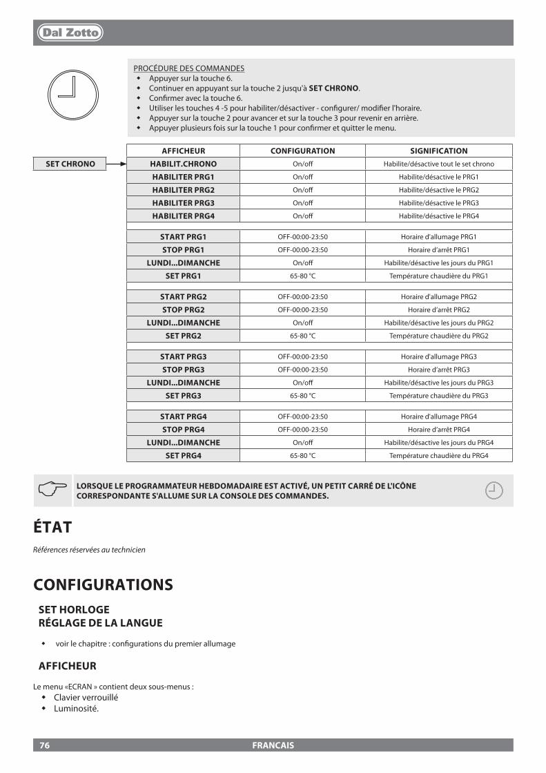
FRANCAIS
JLORSQUE LE PROGRAMMATEUR HEBDOMADAIRE EST ACTIVÉ, UN PETIT CARRÉ DE L'ICÔNE CORRESPONDANTE S'ALLUME SUR LA CONSOLE DES COMMANDES.
AFFICHEUR CONFIGURATION SIGNIFICATION
SET CHRONO HABILIT.CHRONO On/o� Habilite/désactive tout le set chrono
HABILITER PRG1 On/o� Habilite/désactive le PRG1
HABILITER PRG2 On/o� Habilite/désactive le PRG2
HABILITER PRG3 On/o� Habilite/désactive le PRG3
HABILITER PRG4 On/o� Habilite/désactive le PRG4
START PRG1 OFF-00:00-23:50 Horaire d'allumage PRG1
STOP PRG1 OFF-00:00-23:50 Horaire d’arrêt PRG1
LUNDI...DIMANCHE On/o� Habilite/désactive les jours du PRG1
SET PRG1 65-80 °C Température chaudière du PRG1
START PRG2 OFF-00:00-23:50 Horaire d'allumage PRG2
STOP PRG2 OFF-00:00-23:50 Horaire d’arrêt PRG2
LUNDI...DIMANCHE On/o� Habilite/désactive les jours du PRG2
SET PRG2 65-80 °C Température chaudière du PRG2
START PRG3 OFF-00:00-23:50 Horaire d'allumage PRG3
STOP PRG3 OFF-00:00-23:50 Horaire d’arrêt PRG3
LUNDI...DIMANCHE On/o� Habilite/désactive les jours du PRG3
SET PRG3 65-80 °C Température chaudière du PRG3
START PRG4 OFF-00:00-23:50 Horaire d'allumage PRG4
STOP PRG4 OFF-00:00-23:50 Horaire d’arrêt PRG4
LUNDI...DIMANCHE On/o� Habilite/désactive les jours du PRG4
SET PRG4 65-80 °C Température chaudière du PRG4
PROCÉDURE DES COMMANDES� Appuyer sur la touche 6.� Continuer en appuyant sur la touche 2 jusqu'à SET CHRONO.� Con�rmer avec la touche 6.� Utiliser les touches 4 -5 pour habiliter/désactiver - con�gurer/ modi�er l'horaire.� Appuyer sur la touche 2 pour avancer et sur la touche 3 pour revenir en arrière.� Appuyer plusieurs fois sur la touche 1 pour con�rmer et quitter le menu.
ÉTATRéférences réservées au technicien
CONFIGURATIONSSET HORLOGE RÉGLAGE DE LA LANGUE
� voir le chapitre : con�gurations du premier allumage
AFFICHEUR
Le menu «ECRAN » contient deux sous-menus :� Clavier verrouillé� Luminosité.
76
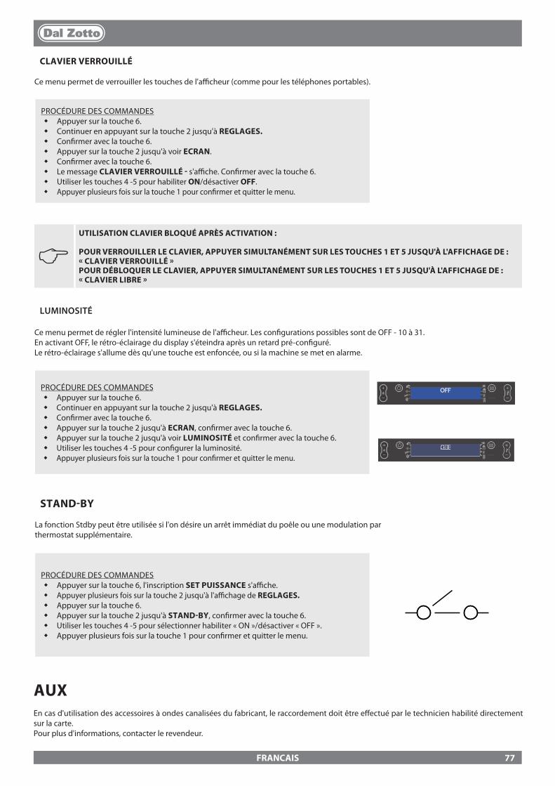
FRANCAIS
J UTILISATION CLAVIER BLOQUÉ APRÈS ACTIVATION :
POUR VERROUILLER LE CLAVIER, APPUYER SIMULTANÉMENT SUR LES TOUCHES 1 ET 5 JUSQU'À L'AFFICHAGE DE : « CLAVIER VERROUILLÉ » POUR DÉBLOQUER LE CLAVIER, APPUYER SIMULTANÉMENT SUR LES TOUCHES 1 ET 5 JUSQU'À L'AFFICHAGE DE : « CLAVIER LIBRE »
LUMINOSITÉ
Ce menu permet de régler l'intensité lumineuse de l'a�cheur. Les con�gurations possibles sont de OFF - 10 à 31.En activant OFF, le rétro-éclairage du display s'éteindra après un retard pré-con�guré. Le rétro-éclairage s'allume dès qu'une touche est enfoncée, ou si la machine se met en alarme.
PROCÉDURE DES COMMANDES� Appuyer sur la touche 6.� Continuer en appuyant sur la touche 2 jusqu'à REGLAGES.� Con�rmer avec la touche 6.� Appuyer sur la touche 2 jusqu'à ECRAN, con�rmer avec la touche 6.� Appuyer sur la touche 2 jusqu'à voir LUMINOSITÉ et con�rmer avec la touche 6.� Utiliser les touches 4 -5 pour con�gurer la luminosité.� Appuyer plusieurs fois sur la touche 1 pour con�rmer et quitter le menu.
OFF
OFF
CLAVIER VERROUILLÉ
Ce menu permet de verrouiller les touches de l'a�cheur (comme pour les téléphones portables).
PROCÉDURE DES COMMANDES� Appuyer sur la touche 6.� Continuer en appuyant sur la touche 2 jusqu'à REGLAGES.� Con�rmer avec la touche 6.� Appuyer sur la touche 2 jusqu'à voir ECRAN.� Con�rmer avec la touche 6.� Le message CLAVIER VERROUILLÉ - s'a�che. Con�rmer avec la touche 6.� Utiliser les touches 4 -5 pour habiliter ON/désactiver OFF.� Appuyer plusieurs fois sur la touche 1 pour con�rmer et quitter le menu.
STAND-BY
La fonction Stdby peut être utilisée si l'on désire un arrêt immédiat du poêle ou une modulation parthermostat supplémentaire.
PROCÉDURE DES COMMANDES� Appuyer sur la touche 6, l'inscription SET PUISSANCE s'a�che.� Appuyer plusieurs fois sur la touche 2 jusqu'à l'a�chage de REGLAGES.� Appuyer sur la touche 6.� Appuyer sur la touche 2 jusqu'à STAND-BY, con�rmer avec la touche 6.� Utiliser les touches 4 -5 pour sélectionner habiliter « ON »/désactiver « OFF ».� Appuyer plusieurs fois sur la touche 1 pour con�rmer et quitter le menu.
AUXEn cas d'utilisation des accessoires à ondes canalisées du fabricant, le raccordement doit être e�ectué par le technicien habilité directement sur la carte.Pour plus d'informations, contacter le revendeur.
77
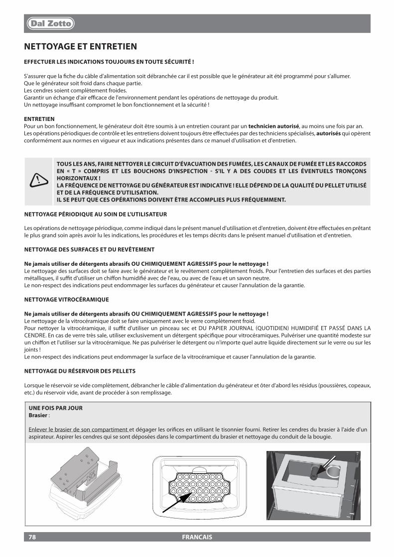
FRANCAIS
NETTOYAGE ET ENTRETIENEFFECTUER LES INDICATIONS TOUJOURS EN TOUTE SÉCURITÉ !
S'assurer que la �che du câble d'alimentation soit débranchée car il est possible que le générateur ait été programmé pour s'allumer. Que le générateur soit froid dans chaque partie.Les cendres soient complètement froides.Garantir un échange d'air e�cace de l'environnement pendant les opérations de nettoyage du produit.Un nettoyage insu�sant compromet le bon fonctionnement et la sécurité !
ENTRETIENPour un bon fonctionnement, le générateur doit être soumis à un entretien courant par un technicien autorisé, au moins une fois par an.Les opérations périodiques de contrôle et les entretiens doivent toujours être e�ectuées par des techniciens spécialisés, autorisés qui opèrent conformément aux normes en vigueur et aux indications présentes dans ce manuel d'utilisation et d'entretien.
UNE FOIS PAR JOUR Brasier :
Enlever le brasier de son compartiment et dégager les ori�ces en utilisant le tisonnier fourni. Retirer les cendres du brasier à l'aide d'un aspirateur. Aspirer les cendres qui se sont déposées dans le compartiment du brasier et nettoyage du conduit de la bougie.
TOUS LES ANS, FAIRE NETTOYER LE CIRCUIT D'ÉVACUATION DES FUMÉES, LES CANAUX DE FUMÉE ET LES RACCORDS EN « T » COMPRIS ET LES BOUCHONS D'INSPECTION - S'IL Y A DES COUDES ET LES ÉVENTUELS TRONÇONS HORIZONTAUX !LA FRÉQUENCE DE NETTOYAGE DU GÉNÉRATEUR EST INDICATIVE ! ELLE DÉPEND DE LA QUALITÉ DU PELLET UTILISÉ ET DE LA FRÉQUENCE D'UTILISATION. IL SE PEUT QUE CES OPÉRATIONS DOIVENT ÊTRE ACCOMPLIES PLUS FRÉQUEMMENT.
NETTOYAGE PÉRIODIQUE AU SOIN DE L'UTILISATEUR
Les opérations de nettoyage périodique, comme indiqué dans le présent manuel d'utilisation et d'entretien, doivent être e�ectuées en prêtant le plus grand soin après avoir lu les indications, les procédures et les temps décrits dans le présent manuel d'utilisation et d'entretien.
NETTOYAGE DES SURFACES ET DU REVÊTEMENT
Ne jamais utiliser de détergents abrasifs OU CHIMIQUEMENT AGRESSIFS pour le nettoyage !Le nettoyage des surfaces doit se faire avec le générateur et le revêtement complètement froids. Pour l'entretien des surfaces et des parties métalliques, il su�t d'utiliser un chi�on humidi�é avec de l'eau, ou avec de l'eau et un savon neutre.Le non-respect des indications peut endommager les surfaces du générateur et causer l'annulation de la garantie.
NETTOYAGE VITROCÉRAMIQUE
Ne jamais utiliser de détergents abrasifs OU CHIMIQUEMENT AGRESSIFS pour le nettoyage !Le nettoyage de la vitrocéramique doit se faire uniquement avec le verre complètement froid. Pour nettoyer la vitrocéramique, il su�t d'utiliser un pinceau sec et DU PAPIER JOURNAL (QUOTIDIEN) HUMIDIFIÉ ET PASSÉ DANS LA CENDRE. En cas de verre très sale, utiliser exclusivement un détergent spéci�que pour vitrocéramiques. Pulvériser une quantité modeste sur un chi�on et l'utiliser sur la vitrocéramique. Ne pas pulvériser le détergent ou n'importe quel autre liquide directement sur le verre ou sur les joints !Le non-respect des indications peut endommager la surface de la vitrocéramique et causer l'annulation de la garantie.
NETTOYAGE DU RÉSERVOIR DES PELLETS
Lorsque le réservoir se vide complètement, débrancher le câble d'alimentation du générateur et ôter d'abord les résidus (poussières, copeaux, etc.) du réservoir vide, avant de procéder à son remplissage.
78

FRANCAIS
UNE FOIS PAR JOURRacleurs :
Le nettoyage des échangeurs thermiques permet de garantir un rendement thermique toujours constant dans le temps. Ce type de maintenance doit être e�ectué au moins une fois par jour. Pour ce faire, il su�t d'utiliser les racleurs prévus situés dans la partie supérieure du poêle, en e�ectuant un mouvement de bas en haut et vice versa plusieurs fois.
UNE FOIS PAR SEMAINE Nettoyage de la chambre de combustion et du tiroir des cendres :
Chaque semaine ou lorsque cela est nécessaire, vider la cendre contenue dans le tiroir prévu à cet e�et. Il est recommandé d'aspirer au moins une fois par semaine les cendres dans la chambre de combustion avec un aspirateur approprié.
Les images sont à titre illustratif
79

FRANCAIS
ENTRETIEN ORDINAIRE EFFECTUÉ PAR DES TECHNICIENS AUTORISÉS
L'entretien courant doit être e�ectué au moins une fois par an.Le générateur, en utilisant du pellet comme combustible solide, nécessite d'une intervention annuelle d'entretien courant, qui doit être e�ectuée par un Technicien autorisé, en utilisant exclusivement des pièces de rechange originales.Le non-respect peut compromettre la sécurité de l'appareil et peut faire déchoir le droit aux conditions de garantie.En respectant les fréquences de nettoyages réservés à l'utilisateur, décrits dans le manuel d'utilisation et d'entretien, on garantit au générateur une bonne combustion dans le temps, en évitant d'éventuelles anomalies et/ou dysfonctionnements, qui pourraient demander de plus grandes interventions du technicien. Les demandes d'interventions d'entretien courant ne sont pas prévues dans la garantie du produit.
JOINTS D'ÉTANCHÉITÉ DE LA PORTE, DU TIROIR À CENDRES ET DU BRASIER
Les joints garantissent l'étanchéité du poêle et par conséquent son bon fonctionnement.Il est nécessaire que ceux-ci soient contrôlés régulièrement : en cas d'usure ou d'endommagement, il faut les remplacer immédiatement.Ces opérations devront être e�ectuées par un technicien autorisé.
RACCORDEMENT À LA CHEMINÉE
Tous les ans ou dans tous les cas à chaque fois que cela est nécessaire, aspirer et nettoyer le conduit qui mène à la cheminée. S'il y a des tronçons horizontaux, il faut enlever les résidus avant qu'ils n'obstruent le passage des fumées.
MISE HORS SERVICE (FIN DE SAISON)À la �n de chaque saison, avant d'éteindre le poêle, il est conseillé de vider complètement le réservoir du pellet, en aspirant d'éventuels résidus de pellet et poussières à l'intérieur.NOUS VOUS CONSEILLONS DE NE PAS DEBRANCHER LE GENERATEUR DU SECTEUR POUR PERMETTRE AU CIRCULATEUR D’EFFECTUER LES CYCLES ANTI-BLOCAGE NORMAUX.L'entretien courant doit être e�ectué au moins une fois par an.
SI LE CÂBLE D'ALIMENTATION EST ENDOMMAGÉ, IL DOIT ÊTRE REMPLACÉ PAR LE SERVICE D'ASSISTANCE TECHNIQUE OU DANS TOUS LES CAS PAR UNE PERSONNE POSSÉDANT UNE QUALIFICATION SEMBLABLE, DE FAÇON À ÉVITER TOUT RISQUE.
UNE FOIS PAR MOIS - JOLE IDRO 2.0
Enlever la cendre qui s'est déposée dans la partie supérieure de la paroi du foyer (voir la �gure ci-dessous).
80
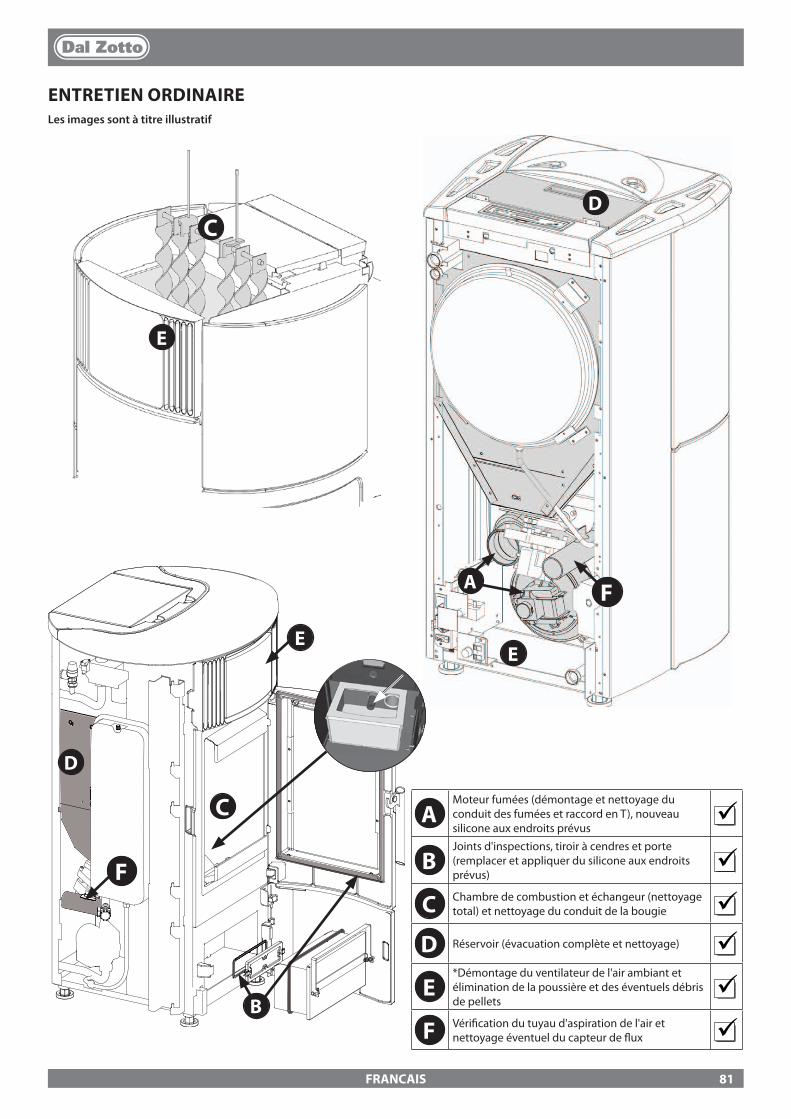
B
E
D
C
A
C
F
D
EE
F
FRANCAIS
ENTRETIEN ORDINAIRELes images sont à titre illustratif
AMoteur fumées (démontage et nettoyage du conduit des fumées et raccord en T), nouveau silicone aux endroits prévus
BJoints d'inspections, tiroir à cendres et porte (remplacer et appliquer du silicone aux endroits prévus)
C Chambre de combustion et échangeur (nettoyage total) et nettoyage du conduit de la bougie
D Réservoir (évacuation complète et nettoyage)
E*Démontage du ventilateur de l'air ambiant et élimination de la poussière et des éventuels débris de pellets
F Véri�cation du tuyau d'aspiration de l'air et nettoyage éventuel du capteur de �ux
81
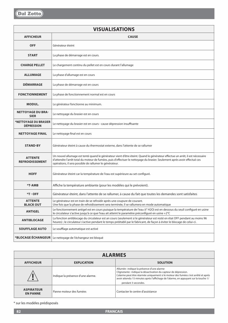
FRANCAIS
VISUALISATIONSAFFICHEUR CAUSE
OFF Générateur éteint
START La phase de démarrage est en cours.
CHARGE PELLET Le chargement continu du pellet est en cours durant l'allumage
ALLUMAGE La phase d'allumage est en cours
DÉMARRAGE La phase de démarrage est en cours
FONCTIONNEMENT La phase de fonctionnement normal est en cours
MODUL. Le générateur fonctionne au minimum.
NETTOYAGE DU BRA-SIER
Le nettoyage du brasier est en cours
*NETTOYAGE DU BRASIERDÉPRESSION
Le nettoyage du brasier est en cours - cause dépression insu�sante
NETTOYAGE FINAL Le nettoyage �nal est en cours
STAND-BY Générateur éteint à cause du thermostat externe, dans l'attente de se rallumer
ATTENTE REFROIDISSEMENT
Un nouvel allumage est tenté quand le générateur vient d’être éteint. Quand le générateur e�ectue un arrêt, il est nécessaire d'attendre l’arrêt total du moteur de fumées, puis d'e�ectuer le nettoyage du brasier. Seulement après avoir e�ectué ces opérations, il sera possible de rallumer le générateur.
HOFF Générateur éteint car la température de l'eau est supérieure au set con�guré.
*T-AMB A�che la température ambiante (pour les modèles qui le prévoient).
*T - OFF Générateur éteint, dans l'attente de se rallumer, à cause du fait que toutes les demandes sont satisfaites
ATTENTE BLACK OUT
Le générateur est en train de se refroidir après une coupure de courant. Une fois que la phase de refroidissement sera terminée, il se rallumera en mode automatique
ANTIGEL Le fonctionnement antigel est en cours puisque la température de l'eau (t° H2O) est en dessous du seuil con�guré en usinele circulateur s'active jusqu'à ce que l'eau ait atteint le paramètre précon�guré en usine +2°C
ANTIBLOCAGE La fonction antiblocage du circulateur est an cours (seulement si le générateur est resté en état OFF pendant au moins 96 heures) ; le circulateur s'active pendant le temps préétabli par le fabricant, de façon à éviter le blocage de celui-ci.
SOUFFLAGE AUTO Le sou�age automatique est activé
*BLOCAGE ÉCHANGEUR Le nettoyage de l'échangeur est bloqué
ALARMESAFFICHEUR EXPLICATION SOLUTION
Indique la présence d'une alarme.
Allumée : indique la présence d'une alarmeClignotante : indique la désactivation du capteur de dépression.L'alarme peut être réarmée uniquement si le moteur des fumées s'est arrêté et après avoir attendu 15 minutes après l'a�chage de l'alarme, en appuyant sur la touche 1/
pendant 3 secondes.
ASPIRATEUR EN PANNE
Panne moteur des fumées Contacter le centre d'assistance
* sur les modèles prédisposés
82
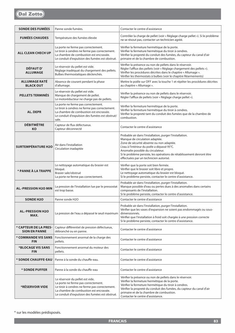
FRANCAIS
* sur les modèles prédisposés.
SONDE DES FUMÉES Panne sonde fumées. Contacter le centre d'assistance
FUMÉES CHAUDES Température des fumées élevée Contrôler la charge de pellet (voir « Réglage charge pellet »). Si le problème ne se résout pas, contacter un technicien agréé.
ALL CLEAN CHECH UP
La porte ne ferme pas correctement.Le tiroir à cendres ne ferme pas correctement.La chambre de combustion est encrassée.Le conduit d'expulsion des fumées est obstrué.
Véri�er la fermeture hermétique de la porte.Véri�er la fermeture hermétique du tiroir à cendres.Véri�er la propreté du conduit des fumées, du capteur du canal d'air primaire et de la chambre de combustion.
DÉFAUT D' ALLUMAGE
Le réservoir du pellet est vide.Réglage inadéquat du chargement des pellets.Bulbes thermostatiques déclenchés.
Véri�er la présence ou non de pellets dans le réservoir.Régler l'a�ux des pellets (voir « Réglage chargement des pellets »).Véri�er les procédures décrites dans le chapitre « Allumage ».Véri�er les thermostats à bulbes (voir le chapitre Réarmements)
ALLUMAGE RATÉ BLACK OUT
Absence de courant pendant la phase d'allumage.
Mettre le poêle sur OFF avec la touche 1 et répéter les procédures décrites au chapitre « Allumage ».
PELLETS TERMINÉS Le réservoir du pellet est vide.Manque de chargement de pellet.Le motoréducteur ne charge pas de pellets.
Véri�er la présence ou non de pellets dans le réservoir.Régler l'a�ux de pellets (voir « Réglage charge pellet »).
AL. DEPR
La porte ne ferme pas correctement.Le tiroir à cendres ne ferme pas correctement.La chambre de combustion est encrassée.Le conduit d'expulsion des fumées est obstrué/sale.
Véri�er la fermeture hermétique de la porte.Véri�er la fermeture hermétique du tiroir à cendres.Véri�er la propreté tant du conduit des fumées que de la chambre de combustion.
DÉBITMÈTRE KO
Capteur de �ux défectueux.Capteur déconnecté Contacter le centre d'assistance
SURTEMPÉRATURE H2O Air dans l'installationCirculation inadaptée
Probable air dans l'installation, purger l'installation.Manque de circulation adaptée.Zone de sécurité absente ou non adaptée.L'eau à l'intérieur du poêle a dépassé 95°C. Anomalie possible du circulateur.Si le problème persiste, les opérations de rétablissement devront être e�ectuées par un technicien autorisé.
* PANNE À LA TRAPPE
Le nettoyage automatique du brasier est bloqué. Brasier sale/obstruéLa porte ne ferme pas correctement.
Véri�er que la porte soit bien fermée.Véri�er que le brasier soit libre et propre.Le nettoyage automatique du brasier est bloqué.Si le problème persiste, contacter le centre d'assistance.
AL.-PRESSION H2O MIN La pression de l'installation lue par le pressostat est trop basse.
Probable air dans l'installation, purger l'installation.Manque possible d'eau ou pertes dues à des anomalies dans certains composants de l'installation.Si le problème persiste, contacter le centre d'assistance.
SONDE H2O Panne sonde H2O Contacter le centre d'assistance
AL.-PRESSION H2O MAX.
La pression de l'eau a dépassé le seuil maximum
Probable air dans l'installation, purger l'installation.Véri�er que les vases d'expansion ne soient pas endommagés ou sous-dimensionnés.Véri�er que l'installation à froid soit chargée à une pression correcteSi le problème persiste, contacter le centre d'assistance.
* CAPTEUR DE LA PRES-SION EN PANNE
Capteur di�érentiel de pression défectueux, débranché ou en panne.
Contacter le centre d'assistance
* COMMANDE VIS SANS FIN
Fonctionnement anormal de la charge des pellets.
Contacter le centre d'assistance
*BLOCAGE VIS SANS FIN
Fonctionnement anormal du moteur des pellets.
Contacter le centre d'assistance
* SONDE CHAUFFE-EAU Panne à la sonde du chau�e-eau. Contacter le centre d'assistance
* SONDE PUFFER Panne à la sonde du chau�e-eau Contacter le centre d'assistance
*RÉSERVOIR VIDE
Le réservoir du pellet est vide. La porte ne ferme pas correctement.Le tiroir à cendres ne ferme pas correctement.La chambre de combustion est encrassée.Le conduit d'expulsion des fumées est obstrué.
Véri�er la présence ou non de pellets dans le réservoir.Véri�er la fermeture hermétique de la porte.Véri�er la fermeture hermétique du tiroir à cendres.Véri�er la propreté du conduit des fumées, du capteur du canal d'air primaire et de la chambre de combustion.Contacter le centre d'assistance.
83
FRANCAIS
1. Les produits DAL ZOTTO, marque commerciale de La Nordica S.p.A. sont garantis, conformément aux directives de la communauté européenne, pour une période de 24 mois à compter de la date d'achat. Un document �scal valide qui prouve l'achat, délivré par le vendeur (ticket de caisse, facture ou bon de transport), identi�ant le produit acheté et la date d'achat et/ou de livraison de ce dernier est nécessaire.
ATTENTION : la présente garantie conventionnelle ne remplace pas la garantie prévue par les normes européennes pour la protection des Consommateurs.
La garantie conventionnelle est limitée au territoire italien et aux territoires compris dans la Communauté européenne couverts par le Service des Centres d'Assistance Technique Agréés (véri�er sur le site www.dalzotto.com)Elle est également limitée au pays de résidence et/ou du domicile du consommateur qui doit être le même que celui du siège légal et/ou commercial du vendeur du produit DAL ZOTTO.Les présentes normes ne s'appliquent pas aux produits achetés dans le cadre d'activités commerciales, d'entreprise ou professionnelles. Dans ces cas, la garantie du produit sera limitée à une période de 12 mois à compter de la date d'achat.
GARANTIE ITALIEQue faire en cas d'anomalie dans le fonctionnement du produit : Consulter le manuel d'utilisation pour s'assurer que l'anomalie ne peut pas être résolue avec une application correcte des fonctionnalités du produit. S'assurer que le défaut rentre dans le type d'anomalies couvertes par la garantie ; si ce n'est pas le cas, le coût de l'intervention sera entièrement à la charge du consommateur. Lors de la demande d'intervention du Service d'Assistance au Centre d'Assistance Agréé, toujours indiquer la nature du défaut, le modèle de l'appareil, une adresse complète et un numéro de téléphone.
GARANTIE EUROPEQue faire en cas d'anomalie dans le fonctionnement du produit : Consulter le manuel d'utilisation pour s'assurer que l'anomalie ne peut pas être résolue avec une application correcte des fonctionnalités du produit. S'assurer que le défaut rentre dans le type d'anomalies couvertes par la garantie ; si ce n'est pas le cas, le coût de l'intervention sera entièrement à la charge du consommateur. Demander l'intervention du Service d'Assistance ou l'adresse du Centre d'Assistance Technique Agréé au vendeur en indiquant toujours la nature du défaut, le modèle de l'appareil, une adresse complète et un numéro de téléphone.
Pour les défauts de conformité apparus dans les 6 premiers mois de vie du produit, la réparation du défaut est couverte par la garantie sans frais pour le consommateur. En cas de vice de conformité relevé entre le septième et le vingt-quatrième mois, le coût de l'appel sera à la charge du consommateur tandis que les frais de la main-d'œuvre et des éventuelles pièces de rechange fonctionnelles utilisées seront à la charge du vendeur.
2. La garantie est exclue si le défaut détecté est dû à des conditions et/ou évènements externes tels que, à titre d'exemple non exhaustif, une capacité insu�sante des systèmes ; une installation erronée et/ou un entretien e�ectué par un personnel non quali�é selon la législation en vigueur dans le pays de résidence du consommateur ; une négligence ; une incapacité d'utilisation et un mauvais entretien par le consommateur, ne correspondant pas à ce qui est indiqué dans le manuel d'utilisation du produit, lequel fait partie intégrante du contrat de vente. La présente garantie ne couvre pas non plus les dommages subis par le produit en l'absence de causes avérées imputables à des vices de fabrication. De la même manière sont exclus de la présente garantie tout vice dû au dysfonctionnement du conduit de cheminée, aux termes de la législation en vigueur dans le pays au moment de l'achat, ainsi que tous les défauts du produit dus à une incurie, rupture accidentelle, altération et/ou dommage dans le transport (rayures, bossellements, etc.), interventions e�ectuées par un personnel non autorisé et autres dommages causés par des interventions erronées du consommateur en essayant de remédier à la panne initiale. La garantie ne couvre pas les matériaux de consommation suivants : les joints, les verres céramiques ou trempés, les revêtements et grilles en fonte, les matériaux réfractaires (ex. Nordiker ou autre), les pièces peintes, chromées ou dorées, les éléments en faïence, les poignées, le brasier et les composants correspondants. Pour les produits Idro, l'échangeur de chaleur est exclu de la garantie si un circuit adapté anti-condensation n'est pas réalisé, qui garantit une température de retour à l'appareil d'au moins 55 degrés. En général la garantie ne couvre pas tous les composants extérieurs au produit sur lesquels le consommateur peut intervenir directement lors de l'utilisation et/ou l'entretien ou qui peuvent être sujets à l'usure et/ou la formation de rouille et de taches sur l'acier dues à une utilisation de détergents agressifs. En cas de réclamation pour un défaut non avéré en phase de véri�cation par un technicien autorisé, l'intervention sera entièrement à la charge du consommateur.
3. S'il s'avère impossible de rétablir la conformité par une réparation du produit/composant, il sera remplacé, sans modi�cation de l'échéance et des termes de garantie acquis au moment de l'achat du produit/composant à remplacer.
4. DAL ZOTTO, marque commerciale de La Nordica S.p.A. décline toute responsabilité en ce qui concerne d'éventuels dommages qui peuvent, directement ou indirectement, être causés à des personnes, animaux et biens personnels en raison de la non-observation de toutes les indications fournies dans le manuel d'utilisation prévu et qui concernent les avertissements au sujet de l'installation, l'utilisation et l'entretien du produit, téléchargeable également sur le site internet.
5. Les interventions d'étalonnage et/ou de réglage du produit en relation au type de combustible ou autre sont exclues de la garantie.
CONDITIONS DE GARANTIE
84
FRANCAIS
6. Si le produit est réparé auprès d'un des Centres d'Assistance Technique Agréés indiqués par DAL ZOTTO et en cas de remplacement du produit, le transport sera gratuit. Si le technicien est en mesure de réparer le produit au domicile de l'utilisateur et que celui-ci refuse, le transport au laboratoire et la livraison de retour seront à sa charge.
7. Au terme des 24 mois de garantie, toute intervention de réparation sera entièrement à la charge du consommateur.
8. En cas de litiges, seul le Tribunal du siège légal de DAL ZOTTO - (Vicence-Italie) sera compétent.
AVERTISSEMENTS SUPPLÉMENTAIRES
� Utiliser exclusivement le combustible recommandé par le fabricant. Le produit ne doit pas être utilisé comme incinérateur. � Ne pas utiliser le produit pour monter dessus ou y poser des objets. � Ne pas mettre de linge à sécher sur le produit. Les étendoirs ou autres doivent être tenus à une distance appropriée du produit. Risque
d'incendie et de dommage au revêtement. � Tout usage inapproprié du produit engage entièrement la responsabilité de l'utilisateur et décharge le fabricant de toute responsabilité
civile et pénale. � Toute altération ou remplacement non autorisés de pièces non originales du produit de quelque type que ce soit peut conduire à un
risque compromettant la sécurité de l'utilisateur et déchargent l'entreprise de toute responsabilité civile et pénale. � La plupart des surfaces du produit sont très chaudes (porte, poignée, vitre, tuyaux de sortie des fumées, etc.). Il faut donc éviter
de toucher ces parties sans porter des vêtements de protection appropriés ou sans utiliser des moyens adaptés, comme des gants de protection thermique.
� Il est interdit de faire fonctionner le produit quand sa porte est ouverte ou lorsque sa vitre est cassée. � Le produit doit être connecté électriquement à un dispositif équipé d'un système de mise à la terre e�cace. � Éteindre le produit en cas de panne ou de dysfonctionnement. � Les pellets accumulés et non brûlés dans le brûleur après chaque « absence d'allumage » doivent être retirés avant tout nouvel allumage.
Contrôler que le brûleur soit propre et bien positionné avant de l'allumer. � Ne pas laver le produit avec de l'eau. L'eau pourrait pénétrer à l'intérieur de l'unité et endommager les isolations électriques, au risque
de provoquer des décharges électriques. � Les installations non conformes aux normes en vigueur de même qu'une utilisation incorrecte et l'absence d'entretien comme le prévoit
le fabricant, entraînent la déchéance de la garantie du produit.
85
DEUTSCH
WARNHINWEISEDiese Bedienungsanleitung ist fester Bestandteil des Produktes: Vergewissern Sie sich, dass sie stets beim Gerät bleibt, auch im Falle einer Übereignung an einen anderen Eigentümer oder Benutzer oder des Umzugs an einen anderen Ort. Bei Beschädigung oder Verlust bitte beim Gebietskundendienst oder Ihrem Fachhändler ein weite-res Exemplar anfordern. Bedienungsanleitungen �nden Sie ebenfalls im Internet auf der Homepage des Unternehmens.Dieses Produkt darf nur zu dem Zweck eingesetzt werden, für den es ausdrücklich gebaut wurde. Jegliche ver-tragliche oder außervertragliche Haftung des Herstellers ist ausgeschlossen, wenn aufgrund von Fehlern bei der Installation, Regulierung und Wartung oder unsachgemäßer Verwendung Schäden an Personen, Tieren oder Dingen hervorgerufen werden.Die Installation muss durch autorisiertes und zugelassenes Personal durchgeführt werden, das die volle Verantwortung für die endgültige Installation und den sich daraus ergebenden Betrieb des installierten Produkts übernimmt. Beachtet werden müssen auch sämtliche Gesetze und Vorschriften, die auf Landes-, Regional-, Provinz- und Gemeindeebene in dem Land gelten, in dem das Gerät installiert wird, sowie die in diesem Handbuch enthaltenen Anweisungen.Es besteht keinerlei Haftung seitens des Herstellers im Fall einer Nichteinhaltung dieser Vorsichtsmaßnah-men.Nach dem Entfernen der Verpackung prüfen, ob der Inhalt unversehrt und komplett ist. Sollten Unregelmäßig-keiten bestehen, wenden Sie sich umgehend an den Händler, bei dem Sie das Gerät gekauft haben.Alle elektrischen Komponenten, die am Ofen vorhanden sind und dessen korrekte Funktion gewährleisten, dür-fen ausschließlich gegen Originalersatzteile und nur durch einen autorisierten Kundendienst ersetzt werden.
SICHERHEIT
� DAS GERÄT DARF VON KINDERN AB 8 JAHREN UND VON PERSONEN MIT EINGESCHRÄNKTEN PHYSISCHEN, SENSORISCHEN ODER GEISTIGEN FÄHIGKEITEN ODER BEI MANGELNDER ERFAHRUNG ODER NOTWENDIGER KENNTNIS BENUTZT WERDEN, SOFERN SIE ÜBERWACHT WERDEN ODER ANWEISUNGEN BEZÜGLICH DES SICHEREN GEBRAUCHS DES GERÄTS ERHIELTEN UND SICH DER DAMIT VERBUNDENEN GEFAHREN BEWUSST SIND.
� DER GEBRAUCH DIESES WÄRMERZEUGERS DURCH PERSONEN (KINDER EINGESCHLOSSEN) MIT EINGESCHRÄNKTEN PHYSISCHEN, SENSORISCHEN ODER PSYCHISCHEN FÄHIGKEITEN IST VERBOTEN UNTERSAGT, ES SEI DENN, SIE WERDEN BEIM GEBRAUCH DES GERÄTES ZUR IHRER EIGENEN SICHERHEIT VON EINER VERANTWORTLICHEN PERSON ÜBERWACHT UND ANGEWIESEN.
� DIE REINIGUNG UND WARTUNG, DESSEN AUSFÜHRUNG DEM BENUTZER UNTERLIEGT, DARF NICHT VON KINDERN OHNE AUFSICHT DURCHGEFÜHRT WERDEN.
� KINDER MÜSSEN BEAUFSICHTIGT WERDEN, DAMIT SIE NICHT MIT DEM GERÄT ODER DER FERNBEDIENUNG SPIELEN.
� DEN WÄRMERZEUGER NICHT BARFUSS ODER MIT NASSEN ODER BZW. FEUCHTEN KÖRPERTEILEN BERÜHREN.
� ES IST VERBOTEN, DIE SICHERHEITSVORRICHTUNGEN OHNE GENEHMIGUNG BZW. ANWEISUNGEN DES HERSTELLERS ZU VER-ÄNDERN ODER EINZUSTELLEN.
� NICHT AN DEN ELEKTRISCHEN LEITUNGEN, DIE AUS DEM PRODUKT KOMMEN, ZIEHEN, DIESE ENTFERNEN ODER VERDREHEN, AUCH WENN DIESER VON DER STROMVERSORGUNG GETRENNT WURDE.
Wir danken Ihnen dafür, dass Sie sich für unsere Firma entschieden haben; unser Produkt ist eine ideale Heizlösung, die auf der neuesten Technologie basiert, sehr hochwertig verarbeitet ist und ein zeitloses Design aufweist, damit Sie stets in aller Sicherheit das fantastische Gefühl genießen können, das Ihnen die Wärme der Flamme geben kann.
86
DEUTSCH
� DAS VERSORGUNGSKABEL SOLLTE SO VERLEGT WERDEN, DASS ES NICHT MIT DEN HEISSEN TEILEN DES GERÄTS IN BERÜH-RUNG KOMMT.
� DER NETZSTECKER MUSS AUCH NACH DER INSTALLATION UNGEHINDERT ZUGÄNGLICH SEIN. � VERMEIDEN SIE ES, EVENTUELL VORHANDENE LÜFTUNGSÖFFNUNGEN ZUM RAUM, IN
WELCHEM DAS GERÄT INSTALLIERT IST, ABZUDECKEN ODER DEREN GRÖSSE ZU VERKLEINERN. � LASSEN SIE BRENNBARE TEILE WIE Z.BSP. VERPACKUNGSMATERIAL, KARTONAGEN, PAPIER
ETC. NICHT IN DER REICHWEITE VON KINDERN ODER BEHINDERTEN PERSONEN OHNE AUFSICHT LIEGEN.
� WÄHREND DES NORMALEN BETRIEBS DES PRODUKTES MUSS DIE FEUERRAUMTÜR STETS GESCHLOSSEN WÄHREND DES BETRIEBS WERDEN DIE AUSSENFLÄCHEN DES GERÄTS HEISS, DAHER RATEN WIR ZUR VORSICHT.
� KONTROLLIEREN SIE VOR DEM EINSCHALTEN NACH EINER LÄNGEREN STILLSTANDSPHASE, OB VERSTOPFUNGEN VORLIEGEN.
� DER WÄRMERZEUGER WURDE SO KONZIPIERT, DASS ER UNTER JEGLICHEN (AUCH KRITISCHEN) KLIMATISCHEN BEDINGUNGEN FUNKTIONIERT. IM FALL VON SPEZIELL UNGÜNSTIGEN WITTERUNGSVERHÄLTNISSEN (STARKER WIND, FROST) KÖNNTEN SICHER-HEITSEINRICHTUNGEN GREIFEN, DIE DEN WÄRMERZEUGER ABSCHALTEN. WENN DIES EINTRITT, WENDEN SIE SICH AN DEN TECHNISCHEN KUNDENDIENST ODER IHREN FACHHÄNDLER. UND SETZEN SIE KEINESFALLS DIE SICHERHEITSVORRICHTUNGEN AUSSER KRAFT!
� IM FALL EINES SCHORNSTEINBRANDES RUFEN SIE SOFORT DIE FEUERWEHR UND IHREN ZUSTÄNDIGEN BEZIRKSSCHORNSTEIN-FEGERMEISTER. VERHINDERN SIE, WENN MÖGLICH, BIS ZUM EINTREFFEN DER FEUERWEHR EIN AUSBREITEN DES BRANDES AUF AN DEN SCHORNSTEIN ANGRENZENDE BRENNBARE BAUTEILE WIE BEISPIELSWEISE MOBILAR, HOLZBAUTEILE WIE HOLZBALKEN, HOLZDECKE ODER BODEN SOWIE TEPPICHE, KABEL ETC.ETC.
� DER WÄRMERZEUGER DARF NICHT ZUR ABFALLVERBRENNUNG BENUTZT WERDEN. � ZUM ANZÜNDEN KEINE ENTFLAMMBARE FLÜSSIGKEIT VERWENDEN. � BEIM EINFÜLLEN DEN PELLETVERPACKUNGSSACK NICHT MIT DEM PRODUKT IN KONTAKT
KOMMEN LASSEN. � DIE OFENKERAMIK WERDEN WIRD HANDWERKLICH HERGESTELLT UND KANN SOMIT
FEINE EINSTICHE,HAARLINIEN UND FARBLICHE UNGLEICHMÄSSIGKEITEN AUFWEISEN. DIESE EIGENSCHAFTEN SIND ZEUGNIS IHRES HOCHWERTIGEN CHARAKTERS. GLASUR UND OFENKERAMIK HABEN UNTERSCHIEDLICHE AUSDEHNUNGSKOEFFIZIENTEN, DADURCH ENTSTEHEN FEINSTE RISSE (HAARLINIEN), DIE IHRE TATSÄCHLICHE ECHTHEIT BEWEISEN. ZUR REINIGUNG DER OFENKERAMIK SOLLTE EIN WEICHES, TROCKENES TUCH VERWENDET WERDEN; BEI VERWENDUNG VON REINIGERN ODER FLÜSSIGKEITEN WÜRDEN DIESE IN DIE HAARRISSE EINDRINGEN UND DIESE HERVORTRETEN LASSEN.
FACHGERECHTE WARTUNGUnter fachgerechter Wartung sind Tätigkeiten zu verstehen, die das Ziel haben, den normalen Verschleiß in Grenzen zu halten, sowie eventuellen Störfällen vorsorglich zu begegnen, welche ein umgehendes Eingreifen erforderlich machen. Bei der fachge-rechten Wartung werden jedoch der Aufbau der Anlage, an der eingegrif-fen wird, oder ihre Nutzungsbestimmung nach den Vorschriften der geltenden technischen Bestimmungen und gemäß Gebrauchs- und Wartungsanleitung des Herstellers nicht verändert.
87
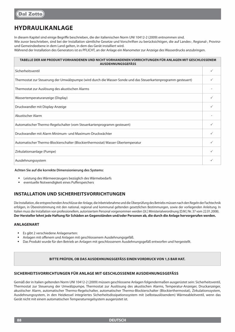
DEUTSCH
HYDRAULIKANLAGEIn diesem Kapitel sind einige Begri�e beschrieben, die der italienischen Norm UNI 10412-2 (2009) entnommen sind. Wie zuvor beschrieben, sind bei der Installation sämtliche Gesetze und Vorschriften zu berücksichtigen, die auf Landes-, Regional-, Provinz- und Gemeindeebene in dem Land gelten, in dem das Gerät installiert wird.Während der Installation des Generators ist es PFLICHT, an der Anlage ein Manometer zur Anzeige des Wasserdrucks anzubringen.
TABELLE DER AM PRODUKT VORHANDENEN UND NICHT VORHANDENEN VORRICHTUNGEN FÜR ANLAGEN MIT GESCHLOSSENEM AUSDEHNUNGSGEFÄSS
Sicherheitsventil p
Thermostat zur Steuerung der Umwälzpumpe (wird durch die Wasser-Sonde und das Steuerkartenprogramm gesteuert) p
Thermostat zur Auslösung des akustischen Alarms -
Wassertemperaturanzeige (Display) p
Druckwandler mit Display-Anzeige p
Akustischer Alarm -
Automatischer Thermo-Regelschalter (vom Steuerkartenprogramm gesteuert) p
Druckwandler mit Alarm Minimum- und Maximum-Druckwächter p
Automatischer Thermo-Blockierschalter (Blockierthermostat) Wasser-Übertemperatur p
Zirkulationsanlage (Pumpe) p
Ausdehnungssystem p
INSTALLATION UND SICHERHEITSVORRICHTUNGEN
Die Installation, die entsprechenden Anschlüsse der Anlage, die Inbetriebnahme und die Überprüfung des Betriebs müssen nach den Regeln der Fachtechnik erfolgen, in Übereinstimmung mit den national, regional und kommunal geltenden gesetzlichen Bestimmungen, sowie der vorliegenden Anleitung. In Italien muss die Installation von professionellem, autorisiertem Personal vorgenommen werden ([it.] Ministerialverordnung [D.M.] Nr. 37 vom 22.01.2008).Der Hersteller lehnt jede Haftung für Schäden an Gegenständen und/oder Personen ab, die durch die Anlage hervorgerufen werden.
ANLAGENART
� Es gibt 2 verschiedene Anlagenarten: � Anlagen mit o�enem und Anlagen mit geschlossenem Ausdehnungsgefäß. � Das Produkt wurde für den Betrieb an Anlagen mit geschlossenem Ausdehnungsgefäß entworfen und hergestellt.
BITTE PRÜFEN, OB DAS AUSDEHNUNGSGEFÄSS EINEN VORDRUCK VON 1,5 BAR HAT.
SICHERHEITSVORRICHTUNGEN FÜR ANLAGE MIT GESCHLOSSENEM AUSDEHNUNGSGEFÄSS
Gemäß der in Italien geltenden Norm UNI 10412-2 (2009) müssen geschlossene Anlagen folgendermaßen ausgerüstet sein: Sicherheitsventil, Thermostat zur Steuerung der Umwälzpumpe, Thermostat zur Auslösung des akustischen Alarms, Temperatur-Anzeiger, Druckanzeiger, akustischer Alarm, automatischer Thermo-Regelschalter, automatischer Thermo-Blockierschalter (Blockierthermostat), Zirkulationssystem, Ausdehnungssystem, in den Heizkessel integriertes Sicherheitsdissipationssystem mit (selbstauslösendem) Wärmeableitventil, wenn das Gerät nicht mit einem automatischen Temperaturregelsystem ausgerüstet ist.
Achten Sie auf die korrekte Dimensionierung des Systems:
� Leistung des Wärmeerzeugers bezüglich des Wärmebedarfs � eventuelle Notwendigkeit eines Pu�erspeichers
88

DEUTSCH
VORSCHRIFTSGEMÄSSE ABSTÄNDE DER SICHERHEITSVORRICHTUNGENDie Sicherheitstemperaturfühler müssen direkt am Gerät oder im Abstand von nicht mehr als 30 cm vom Vorlaufanschluss angeordnet sein. Sollten die Wärmeerzeuger nicht mit allen Vorrichtungen versehen sein, können die fehlenden an der Vorlau�eitung des Erzeugers in einem Abstand von höchstens 1 m vom Gerät installiert werden.
KONTROLLEN BEI DER ERSTMALIGEN ZÜNDUNGVor dem Anschluss des Heizkessels ist für Folgendes zu sorgen:a) Sorgfältige Spülung aller Leitungen der Anlage, um eventuelle Rückstände zu entfernen, die den Betrieb einzelner Bauteile der Anlage (Pumpen, Ventile, usw.) beeinträchtigen könnten.b) Das Unternehmen emp�ehlt nachdrücklich, in den Rücklauf des Generators einen Magnet�lter zu installieren, der die Lebensdauer des Heizkessels verlängert, die Beseitigung von Verunreinigungen fördert und die Gesamte�zienz der Anlage erhöht.c) Eine Kontrolle, um zu überprüfen, ob der Schornstein einen ausreichenden Zug hat und keine Einschnürungen aufweist und ob im Schornstein keine Rauchabzüge anderer Geräte vorhanden sind. Dies dient dazu, nicht vorhergesehene Leistungsanstiege zu verhindern. Erst nach dieser Kontrolle darf der Schornsteinanschluss zwischen Kessel und Schornstein montiert werden. Bei bereits vorhandenen Schornsteinen sollten die Anschlüsse überprüft werden.
VORRICHTUNG GEGEN KONDENSATBILDUNG (VERPFLICHTEND)Es ist P�icht, einen angemessenen Kreislauf gegen Kondensatbildung zu erstellen, der eine Rücklauftemperatur von mindestens 55°C gewährleistet. Das Kondensbildung verhindernde Ventil zum Beispiel wird im Festbrennsto�wärmeerzeuger verwendet, da es den Kaltwasserrück�uss in den Wärmetauscher verhindert. Durch eine hohe Rücklauftemperatur kann die E�zienz verbessert werden, die Kondensatbildung der Rauchgase wird vermindert und die Lebensdauer des Generators verlängert. Der Hersteller emp�ehlt den Gebrauch des Modells 55°C mit hydraulischen Anschlüssen von 1"’.Für Produkte mit Kontrolle der PWM - Pumpe hält man die Installation bezüglich der Erstellung eines angemessenen Kreislaufs gegen Kondensatbildung für gleichwertig im Falle, dass
- Die Umwälzpumpe des Wärmeerzeugers einzig in der Anlage ist, oder- zwischen dem Wärmeerzeuger und der Anlage ein Plattenwärmetauscher angeordnet ist, oder- zwischen dem Wärmeerzeuger und der Anlage ein hydraulischer Kompensator oder Pu�erspeicher besteht (Pu�er)
Ventil als Zubehör erhältlich (Option)
89
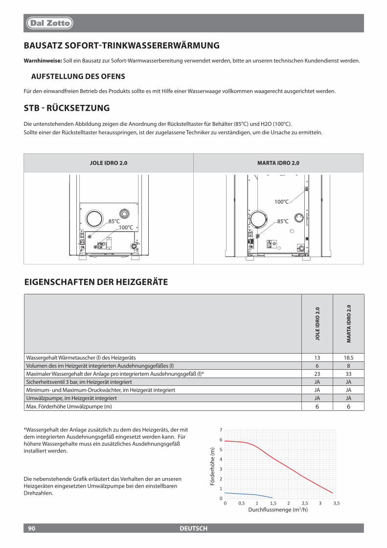
0
1
2
3
4
5
6
7
0 0,5 1 1,5 2 2,5 3 3,5
JOLE IDRO 2.0 MARTA IDRO 2.0
85°C 100°C
85°C 85°C
100°C
100°C
85°C 100°C
85°C 85°C
100°C
100°C
DEUTSCH
BAUSATZ SOFORT-TRINKWASSERERWÄRMUNGWarnhinweise: Soll ein Bausatz zur Sofort-Warmwasserbereitung verwendet werden, bitte an unseren technischen Kundendienst werden.
AUFSTELLUNG DES OFENS
Für den einwandfreien Betrieb des Produkts sollte es mit Hilfe einer Wasserwaage vollkommen waagerecht ausgerichtet werden.
STB - RÜCKSETZUNG
Die untenstehenden Abbildung zeigen die Anordnung der Rückstelltaster für Behälter (85°C) und H2O (100°C).Sollte einer der Rückstelltaster herausspringen, ist der zugelassene Techniker zu verständigen, um die Ursache zu ermitteln.
*Wassergehalt der Anlage zusätzlich zu dem des Heizgeräts, der mit dem integrierten Ausdehnungsgefäß eingesetzt werden kann. Für höhere Wassergehalte muss ein zusätzliches Ausdehnungsgefäß installiert werden.
Die nebenstehende Gra�k erläutert das Verhalten der an unseren Heizgeräten eingesetzten Umwälzpumpe bei den einstellbaren Drehzahlen.
Durch�ussmenge (m3/h)
Förd
erhö
he (m
)
EIGENSCHAFTEN DER HEIZGERÄTE
JOLE
IDRO
2.0
MA
RTA
IDRO
2.0
Wassergehalt Wärmetauscher (l) des Heizgeräts 13 18.5Volumen des im Heizgerät integrierten Ausdehnungsgefäßes (l) 6 8Maximaler Wassergehalt der Anlage pro integriertem Ausdehnungsgefäß (l)* 23 33Sicherheitsventil 3 bar, im Heizgerät integriert JA JAMinimum- und Maximum-Druckwächter, im Heizgerät integriert JA JAUmwälzpumpe, im Heizgerät integriert JA JAMax. Förderhöhe Umwälzpumpe (m) 6 6
90
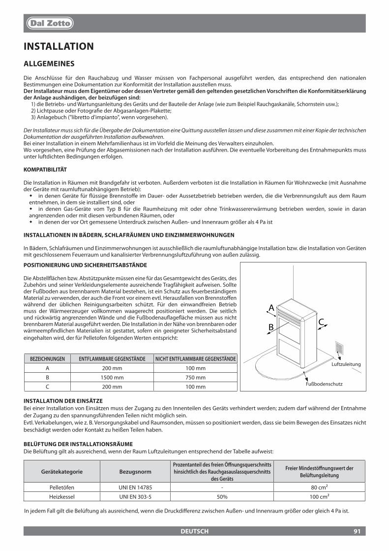
A
CB
DEUTSCH
LuftzuleitungBEZEICHNUNGEN ENTFLAMMBARE GEGENSTÄNDE NICHT ENTFLAMMBARE GEGENSTÄNDE
A 200 mm 100 mm
B 1500 mm 750 mm
C 200 mm 100 mm Fußbodenschutz
INSTALLATION DER EINSÄTZEBei einer Installation von Einsätzen muss der Zugang zu den Innenteilen des Geräts verhindert werden; zudem darf während der Entnahme der Zugang zu den spannungsführenden Teilen nicht möglich sein.Evtl. Verkabelungen, wie z. B. Versorgungskabel und Raumsonden, müssen so positioniert werden, dass sie beim Bewegen des Einsatzes nicht beschädigt werden oder Kontakt zu heißen Teilen haben.
BELÜFTUNG DER INSTALLATIONSRÄUMEDie Belüftung gilt als ausreichend, wenn der Raum Luftzuleitungen entsprechend der Tabelle aufweist:
Gerätekategorie BezugsnormProzentanteil des freien Ö�nungsquerschnitts hinsichtlich des Rauchgasauslassquerschnitts
des Geräts
Freier Mindestö�nungswert der Belüftungsleitung
Pelletöfen UNI EN 14785 - 80 cm²
Heizkessel UNI EN 303-5 50% 100 cm²
In jedem Fall gilt die Belüftung als ausreichend, wenn die Druckdi�erenz zwischen Außen- und Innenraum größer oder gleich 4 Pa ist.
INSTALLATION
ALLGEMEINES
Die Anschlüsse für den Rauchabzug und Wasser müssen von Fachpersonal ausgeführt werden, das entsprechend den nationalen Bestimmungen eine Dokumentation zur Konformität der Installation ausstellen muss.Der Installateur muss dem Eigentümer oder dessen Vertreter gemäß den geltenden gesetzlichen Vorschriften die Konformitätserklärung der Anlage aushändigen, der beizufügen sind:
1) die Betriebs- und Wartungsanleitung des Geräts und der Bauteile der Anlage (wie zum Beispiel Rauchgaskanäle, Schornstein usw.);2) Lichtpause oder Fotogra�e der Abgasanlagen-Plakette;3) Anlagebuch ("libretto d'impianto", wenn vorgesehen).
Der Installateur muss sich für die Übergabe der Dokumentation eine Quittung ausstellen lassen und diese zusammen mit einer Kopie der technischen Dokumentation der ausgeführten Installation aufbewahren.Bei einer Installation in einem Mehrfamilienhaus ist im Vorfeld die Meinung des Verwalters einzuholen.Wo vorgesehen, eine Prüfung der Abgasemissionen nach der Installation ausführen. Die eventuelle Vorbereitung des Entnahmepunkts muss unter luftdichten Bedingungen erfolgen.
KOMPATIBILITÄT
Die Installation in Räumen mit Brandgefahr ist verboten. Außerdem verboten ist die Installation in Räumen für Wohnzwecke (mit Ausnahme der Geräte mit raumluftunabhängigem Betrieb):
� in denen Geräte für �üssige Brennsto�e im Dauer- oder Aussetzbetrieb betrieben werden, die die Verbrennungsluft aus dem Raum entnehmen, in dem sie installiert sind, oder
� in denen Gas-Geräte vom Typ B für die Raumheizung mit oder ohne Trinkwassererwärmung betrieben werden, sowie in daran angrenzenden oder mit diesen verbundenen Räumen, oder
� in denen der vor Ort gemessene Unterdruck zwischen Außen- und Innenraum größer als 4 Pa ist
INSTALLATIONEN IN BÄDERN, SCHLAFRÄUMEN UND EINZIMMERWOHNUNGEN
In Bädern, Schlafräumen und Einzimmerwohnungen ist ausschließlich die raumluftunabhängige Installation bzw. die Installation von Geräten mit geschlossenem Feuerraum und kanalisierter Verbrennungsluftzuführung von außen zulässig.
POSITIONIERUNG UND SICHERHEITSABSTÄNDE
Die Abstell�ächen bzw. Abstützpunkte müssen eine für das Gesamtgewicht des Geräts, des Zubehörs und seiner Verkleidungselemente ausreichende Tragfähigkeit aufweisen. Sollte der Fußboden aus brennbarem Material bestehen, ist ein Schutz aus feuerbeständigem Material zu verwenden, der auch die Front vor einem evtl. Herausfallen von Brennsto�en während der üblichen Reinigungsarbeiten schützt. Für den einwandfreien Betrieb muss der Wärmeerzeuger vollkommen waagerecht positioniert werden. Die seitlich und rückwärtig angrenzenden Wände und die Fußbodenau�age�äche müssen aus nicht brennbarem Material ausgeführt werden. Die Installation in der Nähe von brennbaren oder wärmeemp�ndlichen Materialien ist gestattet, sofern ein geeigneter Sicherheitsabstand eingehalten wird, der für Pelletofen folgenden Werten entspricht:
91
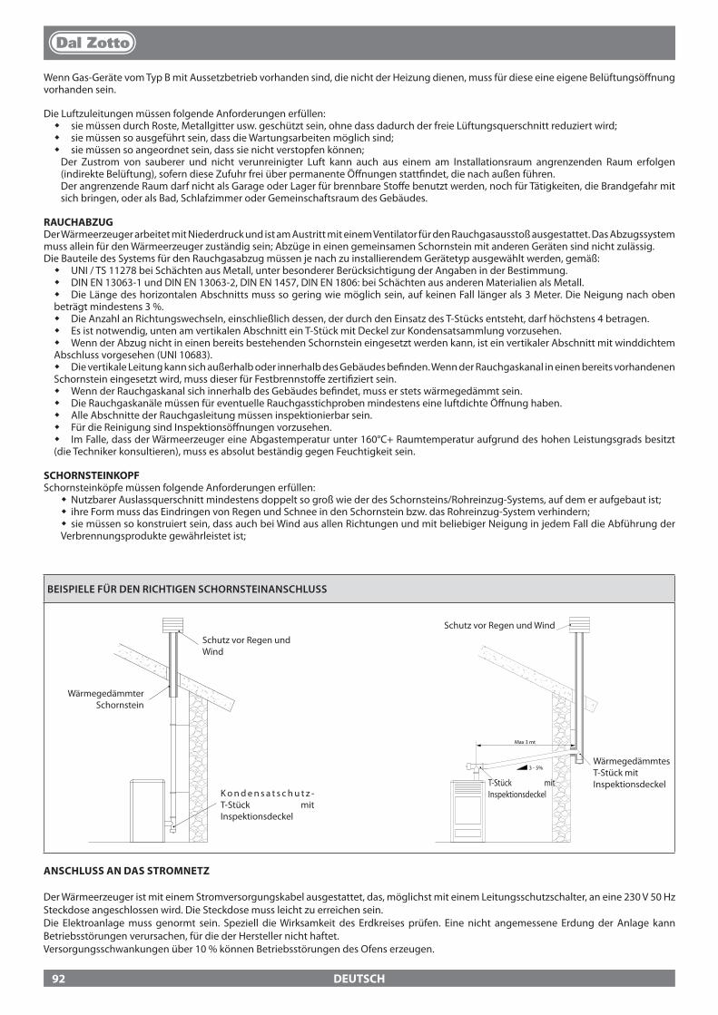
3 - 5%
Max 3 mt
DEUTSCH
BEISPIELE FÜR DEN RICHTIGEN SCHORNSTEINANSCHLUSS
Wenn Gas-Geräte vom Typ B mit Aussetzbetrieb vorhanden sind, die nicht der Heizung dienen, muss für diese eine eigene Belüftungsö�nung vorhanden sein.
Die Luftzuleitungen müssen folgende Anforderungen erfüllen: � sie müssen durch Roste, Metallgitter usw. geschützt sein, ohne dass dadurch der freie Lüftungsquerschnitt reduziert wird; � sie müssen so ausgeführt sein, dass die Wartungsarbeiten möglich sind; � sie müssen so angeordnet sein, dass sie nicht verstopfen können;Der Zustrom von sauberer und nicht verunreinigter Luft kann auch aus einem am Installationsraum angrenzenden Raum erfolgen (indirekte Belüftung), sofern diese Zufuhr frei über permanente Ö�nungen statt�ndet, die nach außen führen.Der angrenzende Raum darf nicht als Garage oder Lager für brennbare Sto�e benutzt werden, noch für Tätigkeiten, die Brandgefahr mit sich bringen, oder als Bad, Schlafzimmer oder Gemeinschaftsraum des Gebäudes.
RAUCHABZUGDer Wärmeerzeuger arbeitet mit Niederdruck und ist am Austritt mit einem Ventilator für den Rauchgasausstoß ausgestattet. Das Abzugssystem muss allein für den Wärmeerzeuger zuständig sein; Abzüge in einen gemeinsamen Schornstein mit anderen Geräten sind nicht zulässig.Die Bauteile des Systems für den Rauchgasabzug müssen je nach zu installierendem Gerätetyp ausgewählt werden, gemäß:
� UNI / TS 11278 bei Schächten aus Metall, unter besonderer Berücksichtigung der Angaben in der Bestimmung. � DIN EN 13063-1 und DIN EN 13063-2, DIN EN 1457, DIN EN 1806: bei Schächten aus anderen Materialien als Metall. � Die Länge des horizontalen Abschnitts muss so gering wie möglich sein, auf keinen Fall länger als 3 Meter. Die Neigung nach oben
beträgt mindestens 3 %. � Die Anzahl an Richtungswechseln, einschließlich dessen, der durch den Einsatz des T-Stücks entsteht, darf höchstens 4 betragen. � Es ist notwendig, unten am vertikalen Abschnitt ein T-Stück mit Deckel zur Kondensatsammlung vorzusehen. � Wenn der Abzug nicht in einen bereits bestehenden Schornstein eingesetzt werden kann, ist ein vertikaler Abschnitt mit winddichtem
Abschluss vorgesehen (UNI 10683). � Die vertikale Leitung kann sich außerhalb oder innerhalb des Gebäudes be�nden. Wenn der Rauchgaskanal in einen bereits vorhandenen
Schornstein eingesetzt wird, muss dieser für Festbrennsto�e zerti�ziert sein. � Wenn der Rauchgaskanal sich innerhalb des Gebäudes be�ndet, muss er stets wärmegedämmt sein. � Die Rauchgaskanäle müssen für eventuelle Rauchgasstichproben mindestens eine luftdichte Ö�nung haben. � Alle Abschnitte der Rauchgasleitung müssen inspektionierbar sein. � Für die Reinigung sind Inspektionsö�nungen vorzusehen. � Im Falle, dass der Wärmeerzeuger eine Abgastemperatur unter 160°C+ Raumtemperatur aufgrund des hohen Leistungsgrads besitzt
(die Techniker konsultieren), muss es absolut beständig gegen Feuchtigkeit sein.
SCHORNSTEINKOPFSchornsteinköpfe müssen folgende Anforderungen erfüllen:
� Nutzbarer Auslassquerschnitt mindestens doppelt so groß wie der des Schornsteins/Rohreinzug-Systems, auf dem er aufgebaut ist; � ihre Form muss das Eindringen von Regen und Schnee in den Schornstein bzw. das Rohreinzug-System verhindern; � sie müssen so konstruiert sein, dass auch bei Wind aus allen Richtungen und mit beliebiger Neigung in jedem Fall die Abführung der
Verbrennungsprodukte gewährleistet ist;
Schutz vor Regen und Wind
K o n d e n s a t s c h u t z -T-Stück mit Inspektionsdeckel
Wärmegedämmter Schornstein
Wärmegedämmtes T-Stück mit Inspektionsdeckel
Schutz vor Regen und Wind
T-Stück mit Inspektionsdeckel
ANSCHLUSS AN DAS STROMNETZ
Der Wärmeerzeuger ist mit einem Stromversorgungskabel ausgestattet, das, möglichst mit einem Leitungsschutzschalter, an eine 230 V 50 Hz Steckdose angeschlossen wird. Die Steckdose muss leicht zu erreichen sein.Die Elektroanlage muss genormt sein. Speziell die Wirksamkeit des Erdkreises prüfen. Eine nicht angemessene Erdung der Anlage kann Betriebsstörungen verursachen, für die der Hersteller nicht haftet. Versorgungsschwankungen über 10 % können Betriebsstörungen des Ofens erzeugen.
92
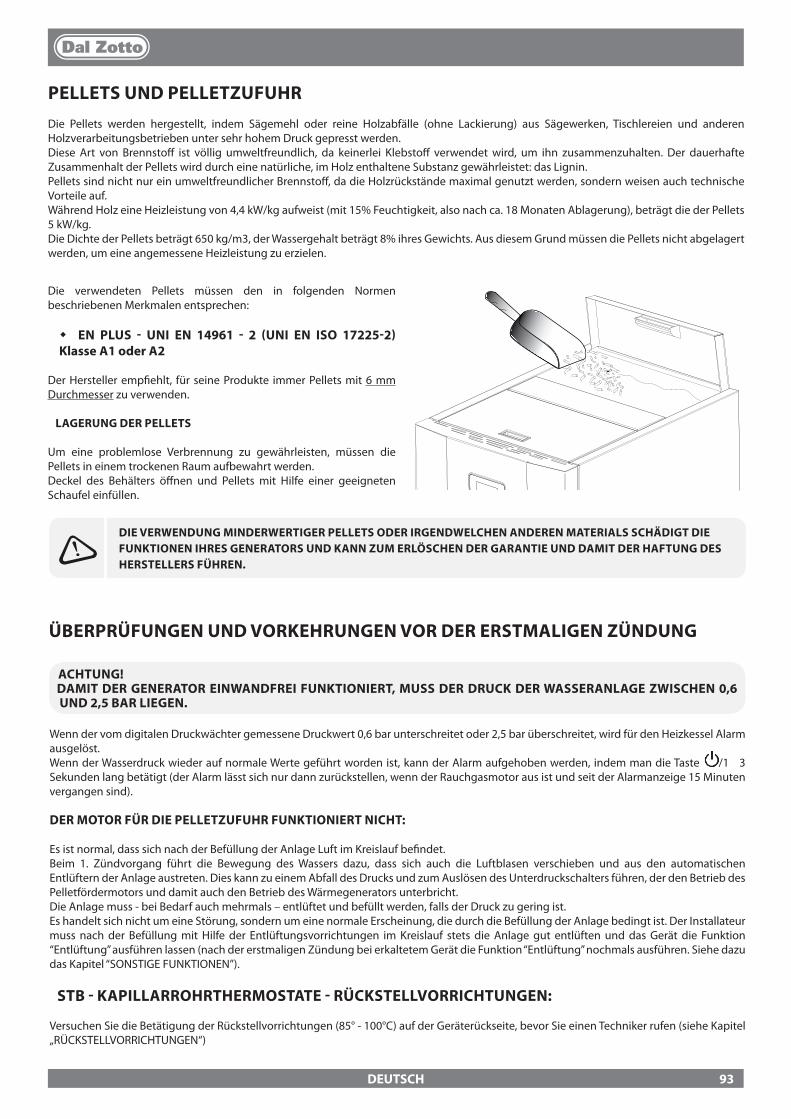
DEUTSCH
PELLETS UND PELLETZUFUHRDie Pellets werden hergestellt, indem Sägemehl oder reine Holzabfälle (ohne Lackierung) aus Sägewerken, Tischlereien und anderen Holzverarbeitungsbetrieben unter sehr hohem Druck gepresst werden.Diese Art von Brennsto� ist völlig umweltfreundlich, da keinerlei Klebsto� verwendet wird, um ihn zusammenzuhalten. Der dauerhafte Zusammenhalt der Pellets wird durch eine natürliche, im Holz enthaltene Substanz gewährleistet: das Lignin.Pellets sind nicht nur ein umweltfreundlicher Brennsto�, da die Holzrückstände maximal genutzt werden, sondern weisen auch technische Vorteile auf.Während Holz eine Heizleistung von 4,4 kW/kg aufweist (mit 15% Feuchtigkeit, also nach ca. 18 Monaten Ablagerung), beträgt die der Pellets 5 kW/kg.Die Dichte der Pellets beträgt 650 kg/m3, der Wassergehalt beträgt 8% ihres Gewichts. Aus diesem Grund müssen die Pellets nicht abgelagert werden, um eine angemessene Heizleistung zu erzielen.
DIE VERWENDUNG MINDERWERTIGER PELLETS ODER IRGENDWELCHEN ANDEREN MATERIALS SCHÄDIGT DIE FUNKTIONEN IHRES GENERATORS UND KANN ZUM ERLÖSCHEN DER GARANTIE UND DAMIT DER HAFTUNG DES HERSTELLERS FÜHREN.
Die verwendeten Pellets müssen den in folgenden Normen beschriebenen Merkmalen entsprechen:
� EN PLUS - UNI EN 14961 - 2 (UNI EN ISO 17225-2) Klasse A1 oder A2
Der Hersteller emp�ehlt, für seine Produkte immer Pellets mit 6 mm Durchmesser zu verwenden.
LAGERUNG DER PELLETS
Um eine problemlose Verbrennung zu gewährleisten, müssen die Pellets in einem trockenen Raum aufbewahrt werden.Deckel des Behälters ö�nen und Pellets mit Hilfe einer geeigneten Schaufel einfüllen.
ÜBERPRÜFUNGEN UND VORKEHRUNGEN VOR DER ERSTMALIGEN ZÜNDUNG
ACHTUNG!DAMIT DER GENERATOR EINWANDFREI FUNKTIONIERT, MUSS DER DRUCK DER WASSERANLAGE ZWISCHEN 0,6 UND 2,5 BAR LIEGEN.
Wenn der vom digitalen Druckwächter gemessene Druckwert 0,6 bar unterschreitet oder 2,5 bar überschreitet, wird für den Heizkessel Alarm ausgelöst.Wenn der Wasserdruck wieder auf normale Werte geführt worden ist, kann der Alarm aufgehoben werden, indem man die Taste /1 3 Sekunden lang betätigt (der Alarm lässt sich nur dann zurückstellen, wenn der Rauchgasmotor aus ist und seit der Alarmanzeige 15 Minuten vergangen sind).
DER MOTOR FÜR DIE PELLETZUFUHR FUNKTIONIERT NICHT:
Es ist normal, dass sich nach der Befüllung der Anlage Luft im Kreislauf be�ndet.Beim 1. Zündvorgang führt die Bewegung des Wassers dazu, dass sich auch die Luftblasen verschieben und aus den automatischen Entlüftern der Anlage austreten. Dies kann zu einem Abfall des Drucks und zum Auslösen des Unterdruckschalters führen, der den Betrieb des Pelletfördermotors und damit auch den Betrieb des Wärmegenerators unterbricht.Die Anlage muss - bei Bedarf auch mehrmals – entlüftet und befüllt werden, falls der Druck zu gering ist.Es handelt sich nicht um eine Störung, sondern um eine normale Erscheinung, die durch die Befüllung der Anlage bedingt ist. Der Installateur muss nach der Befüllung mit Hilfe der Entlüftungsvorrichtungen im Kreislauf stets die Anlage gut entlüften und das Gerät die Funktion “Entlüftung” ausführen lassen (nach der erstmaligen Zündung bei erkaltetem Gerät die Funktion “Entlüftung” nochmals ausführen. Siehe dazu das Kapitel “SONSTIGE FUNKTIONEN”).
STB - KAPILLARROHRTHERMOSTATE - RÜCKSTELLVORRICHTUNGEN:
Versuchen Sie die Betätigung der Rückstellvorrichtungen (85° - 100°C) auf der Geräterückseite, bevor Sie einen Techniker rufen (siehe Kapitel „RÜCKSTELLVORRICHTUNGEN“)
93
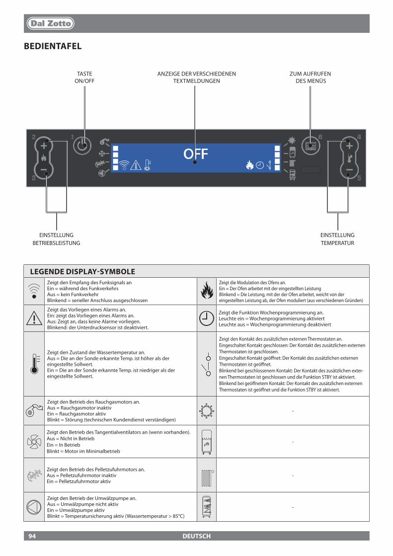
12
3
4
5
6
OFF
DEUTSCH
BEDIENTAFEL
TASTE ON/OFF
ANZEIGE DER VERSCHIEDENEN TEXTMELDUNGEN
ZUM AUFRUFEN DES MENÜS
EINSTELLUNG TEMPERATUR
EINSTELLUNG BETRIEBSLEISTUNG
LEGENDE DISPLAY-SYMBOLEZeigt den Empfang des Funksignals anEin = während des FunkverkehrsAus = kein FunkverkehrBlinkend = serieller Anschluss ausgeschlossen
Zeigt die Modulation des Ofens an.Ein = Der Ofen arbeitet mit der eingestellten LeistungBlinkend = Die Leistung, mit der der Ofen arbeitet, weicht von der eingestellten Leistung ab, der Ofen moduliert (aus verschiedenen Gründen)
Zeigt das Vorliegen eines Alarms an.Ein: zeigt das Vorliegen eines Alarms an.Aus: Zeigt an, dass keine Alarme vorliegen.Blinkend: der Unterdrucksensor ist deaktiviert.
Zeigt die Funktion Wochenprogrammierung an.Leuchte ein = Wochenprogrammierung aktiviertLeuchte aus = Wochenprogrammierung deaktiviert
Zeigt den Zustand der Wassertemperatur an.Aus = Die an der Sonde erkannte Temp. ist höher als der eingestellte Sollwert.Ein = Die an der Sonde erkannte Temp. ist niedriger als der eingestellte Sollwert.
Zeigt den Kontakt des zusätzlichen externen Thermostaten an.Eingeschaltet Kontakt geschlossen: Der Kontakt des zusätzlichen externen Thermostaten ist geschlossen.Eingeschaltet Kontakt geö�net: Der Kontakt des zusätzlichen externen Thermostaten ist geö�net.Blinkend bei geschlossenem Kontakt: Der Kontakt des zusätzlichen exter-nen Thermostaten ist geschlossen und die Funktion STBY ist aktiviert.Blinkend bei geö�netem Kontakt: Der Kontakt des zusätzlichen externen Thermostaten ist geö�net und die Funktion STBY ist aktiviert.
Zeigt den Betrieb des Rauchgasmotors an.Aus = Rauchgasmotor inaktivEin = Rauchgasmotor aktivBlinkt = Störung (technischen Kundendienst verständigen)
-
Zeigt den Betrieb des Tangentialventilators an (wenn vorhanden).Aus = Nicht in BetriebEin = In BetriebBlinkt = Motor im Minimalbetrieb
-
Zeigt den Betrieb des Pelletzufuhrmotors an.Aus = Pelletzufuhrmotor inaktivEin = Pelletzufuhrmotor aktiv
-
Zeigt den Betrieb der Umwälzpumpe an.Aus = Umwälzpumpe nicht aktivEin = Umwälzpumpe aktivBlinkt = Temperatursicherung aktiv (Wassertemperatur > 85°C)
-
94

OFF12
3
4
5
6
1
2 3
4 5
6
12
3
46
5
6
DEUTSCH
ALLGEMEINES MENÜZurück - Ende
Blättern der Parameter: nächster (2); vorheriger (3) Einstelldaten ändern: Erhöhung (4); Verringerung (5)
Bestätigung - Aufrufen des Menüs
SET LEISTUNG LEISTUNG
SET TEMPERATUR RAUM TEMP SET
SET H2O
KUNDEN MENÜ *FREIGABE V1
*V-LUFT-1
SET CHRONO AKTIVIERUNG CHRONO RESET
FREIGABE PRG1 EASY SET UP
FREIGABE PRG2
STATUS **OFEN-STATUS FREIGABE PRG3
FREIGABE PRG4
EINSTELLUNGEN SET STUNDEN START PRG1
SPRACHE STOP PRG1
DISPLAY MONTAG PRG1...
STAND BY ...SONNTAG PRG1
** MENÚTECHNIKER
SET PRG1 * WENN VORHANDEN
** DEM TECHNIKER VORBEHALTEN
DIESELBEN SCHRITTE FÜR DIE ANDEREN 3 ZEITSPANNEN
Die Firma bietet eine optionale Erweiterungskarte, mit der der Heizkessel die folgenden Zusatzfunktionen in der Steuerung der Anlage übernehmen kann. In der untenstehenden Tabelle werden die verschiedenen Möglichkeiten aufgeführt, die das Zubehör bietet.
Steuerung Warmwasserspeicher pSteuerung Pu�erspeicher p3 Heizzonen pOption Sofortwarmwasser pSteuerung Pu�erspeicherpumpe oder 4. Heizzone pSteuerung Legionellenschutz für WW-Speicher pZeitsteuerung WW-Speicher pSteuerung und Kontrolle Nebenausgang p
GRUNDANWEISUNGEN
� Bei den ersten Einschaltungen des Ofens sind die folgenden Ratschläge zu beachten:� Es ist möglich, dass leichte Gerüche entstehen, die auf das Austrocknen der verwendeten Lacke und Silikone zurückzuführen sind. Einen längeren Aufenthalt im Raum vermeiden.� Ober�ächen nicht berühren, da sie noch instabil sein könnten.� Raum mehrmals gut lüften.� Die Aushärtung der Ober�ächen ist nach einigen Heizvorgängen abgeschlossen.� Dieses Gerät darf nicht zur Abfallverbrennung benutzt werden.
� Vor dem Einschalten des Ofens sind folgende Punkte zu überprüfen:� Die Hydraulikanlage muss fertiggestellt sein, die gesetzlichen Vorschriften und die Vorschriften des Handbuchs sind zu beachten.� Der Behälter muss mit Pellets gefüllt sein.� Die Brennkammer muss sauber sein.� Die Brennschale muss völlig frei und sauber sein.� Die hermetische Schließung der Feuertür und des Aschenkastens kontrollieren.� Kontrollieren, dass das Stromversorgungskabel richtig angeschlossen ist.� Der zweipolige Schalter im hinteren rechten Teil muss auf 1 stehen.
95
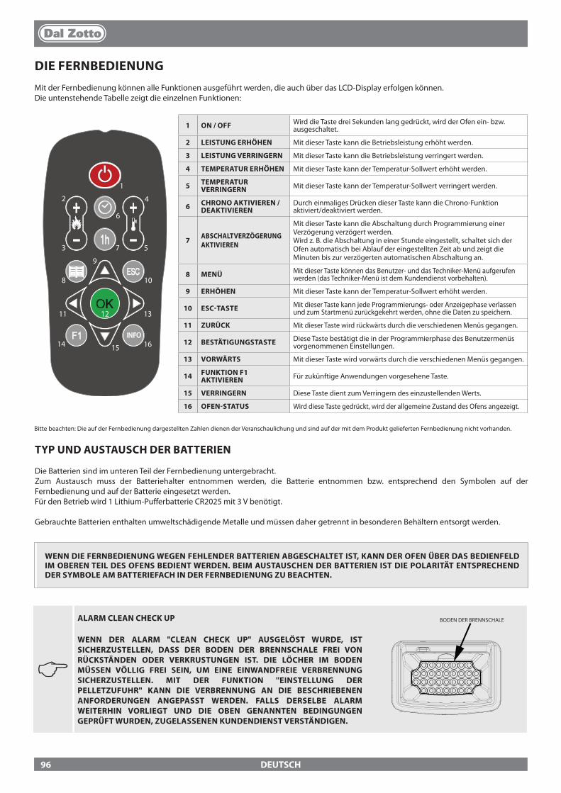
DEUTSCH
DIE FERNBEDIENUNGMit der Fernbedienung können alle Funktionen ausgeführt werden, die auch über das LCD-Display erfolgen können.Die untenstehende Tabelle zeigt die einzelnen Funktionen:
INFO
1
2
3
4
5
6
7
8
9
10
11 12 13
14 15 16
1 ON / OFF Wird die Taste drei Sekunden lang gedrückt, wird der Ofen ein- bzw. ausgeschaltet.
2 LEISTUNG ERHÖHEN Mit dieser Taste kann die Betriebsleistung erhöht werden.
3 LEISTUNG VERRINGERN Mit dieser Taste kann die Betriebsleistung verringert werden.
4 TEMPERATUR ERHÖHEN Mit dieser Taste kann der Temperatur-Sollwert erhöht werden.
5 TEMPERATUR VERRINGERN Mit dieser Taste kann der Temperatur-Sollwert verringert werden.
6 CHRONO AKTIVIEREN / DEAKTIVIEREN
Durch einmaliges Drücken dieser Taste kann die Chrono-Funktion aktiviert/deaktiviert werden.
7 ABSCHALTVERZÖGERUNG AKTIVIEREN
Mit dieser Taste kann die Abschaltung durch Programmierung einer Verzögerung verzögert werden. Wird z. B. die Abschaltung in einer Stunde eingestellt, schaltet sich der Ofen automatisch bei Ablauf der eingestellten Zeit ab und zeigt die Minuten bis zur verzögerten automatischen Abschaltung an.
8 MENÜ Mit dieser Taste können das Benutzer- und das Techniker-Menü aufgerufen werden (das Techniker-Menü ist dem Kundendienst vorbehalten).
9 ERHÖHEN Mit dieser Taste kann der Temperatur-Sollwert erhöht werden.
10 ESC-TASTE Mit dieser Taste kann jede Programmierungs- oder Anzeigephase verlassen und zum Startmenü zurückgekehrt werden, ohne die Daten zu speichern.
11 ZURÜCK Mit dieser Taste wird rückwärts durch die verschiedenen Menüs gegangen.
12 BESTÄTIGUNGSTASTE Diese Taste bestätigt die in der Programmierphase des Benutzermenüs vorgenommenen Einstellungen.
13 VORWÄRTS Mit dieser Taste wird vorwärts durch die verschiedenen Menüs gegangen.
14 FUNKTION F1 AKTIVIEREN Für zukünftige Anwendungen vorgesehene Taste.
15 VERRINGERN Diese Taste dient zum Verringern des einzustellenden Werts.
16 OFEN-STATUS Wird diese Taste gedrückt, wird der allgemeine Zustand des Ofens angezeigt.
TYP UND AUSTAUSCH DER BATTERIEN
Die Batterien sind im unteren Teil der Fernbedienung untergebracht. Zum Austausch muss der Batteriehalter entnommen werden, die Batterie entnommen bzw. entsprechend den Symbolen auf der Fernbedienung und auf der Batterie eingesetzt werden.Für den Betrieb wird 1 Lithium-Pu�erbatterie CR2025 mit 3 V benötigt.
Gebrauchte Batterien enthalten umweltschädigende Metalle und müssen daher getrennt in besonderen Behältern entsorgt werden.
Bitte beachten: Die auf der Fernbedienung dargestellten Zahlen dienen der Veranschaulichung und sind auf der mit dem Produkt gelieferten Fernbedienung nicht vorhanden.
WENN DIE FERNBEDIENUNG WEGEN FEHLENDER BATTERIEN ABGESCHALTET IST, KANN DER OFEN ÜBER DAS BEDIENFELD IM OBEREN TEIL DES OFENS BEDIENT WERDEN. BEIM AUSTAUSCHEN DER BATTERIEN IST DIE POLARITÄT ENTSPRECHEND DER SYMBOLE AM BATTERIEFACH IN DER FERNBEDIENUNG ZU BEACHTEN.
J
ALARM CLEAN CHECK UP
WENN DER ALARM "CLEAN CHECK UP" AUSGELÖST WURDE, IST SICHERZUSTELLEN, DASS DER BODEN DER BRENNSCHALE FREI VON RÜCKSTÄNDEN ODER VERKRUSTUNGEN IST. DIE LÖCHER IM BODEN MÜSSEN VÖLLIG FREI SEIN, UM EINE EINWANDFREIE VERBRENNUNG SICHERZUSTELLEN. MIT DER FUNKTION ''EINSTELLUNG DER PELLETZUFUHR'' KANN DIE VERBRENNUNG AN DIE BESCHRIEBENEN ANFORDERUNGEN ANGEPASST WERDEN. FALLS DERSELBE ALARM WEITERHIN VORLIEGT UND DIE OBEN GENANNTEN BEDINGUNGEN GEPRÜFT WURDEN, ZUGELASSENEN KUNDENDIENST VERSTÄNDIGEN.
BODEN DER BRENNSCHALE
96
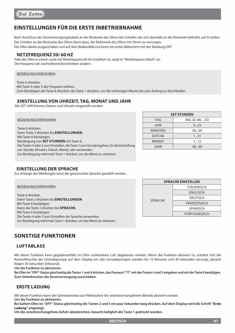
DEUTSCH
EINSTELLUNG VON UHRZEIT, TAG, MONAT UND JAHRMit SET UHR können Datum und Uhrzeit eingestellt werden.
BEDIENUNGSVERFAHREN
Taste 6 drücken.Dann Taste 2 drücken bis EINSTELLUNGEN.Mit Taste 6 bestätigen.Dann die Taste 2 drücken bis SPRACHE.Mit Taste 6 bestätigen.Die Tasten 4 oder 5 zum Einstellen der Sprache verwenden.Zur Bestätigung mehrmals Taste 1 drücken, um das Menü zu verlassen.
SPRACHE EINSTELLEN
SPRACHE
ITALIENISCH
ENGLISCH
DEUTSCH
FRANZÖSISCH
SPANISCH
PORTUGIESISCH
EINSTELLUNGEN FÜR DIE ERSTE INBETRIEBNAHME
Nach Anschluss des Stromversorgungskabels an der Rückseite des Ofens den Schalter, der sich ebenfalls an der Rückseite be�ndet, auf (I) stellen.Der Schalter an der Rückseite des Ofens dient dazu, die Elektronik des Ofens mit Strom zu versorgen.Der Ofen bleibt ausgeschaltet und auf dem Bedienfeld erscheint ein erster Bildschirm mit der Meldung OFF.
SONSTIGE FUNKTIONEN
LUFTABLASS
Mit dieser Funktion kann gegebenenfalls im Ofen vorhandene Luft abgelassen werden. Wenn die Funktion aktiviert ist, schaltet sich die Kontrollleuchte der Umwälzpumpe auf dem Display ein (die Umwälzpumpen werden für 15 Minuten und 30 Sekunden versorgt, danach folgen 30 Sekunden Stillstand).Um die Funktion zu aktivieren:Bei Ofen im "OFF"-Status gleichzeitig die Tasten 1 und 4 drücken, das Passwort "77" mit den Tasten 4 und 5 eingeben und mit der Taste 6 bestätigen. Zum Unterbrechen die Stromversorgung ausschalten.
ERSTE LADUNG
Mit dieser Funktion kann der Getriebemotor zur Pelletzufuhr für unterbrechungsfreien Betrieb aktiviert werden. Um die Funktion zu aktivieren:Bei kaltem Ofen im "OFF"-Status gleichzeitig die Tasten 2 und 5 ein paar Sekunden lang drücken. Auf dem Display wird die Schrift “Erste Ladung” angezeigt.Um die unterbrechungsfreie Zufuhr abzubrechen, braucht lediglich die Taste 1 gedrückt werden.
BEDIENUNGSVERFAHREN
Taste 6 drücken.Dann Taste 2 drücken bis EINSTELLUNGEN.Mit Taste 6 bestätigen.Bestätigung von SET STUNDEN mit Taste 6.Die Tasten 4 oder 5 zum Einstellen, die Taste 2 zum Vorwärtsgehen, für die Einstellung von Stunde, Minuten, Datum, Monat, Jahr verwenden .Zur Bestätigung mehrmals Taste 1 drücken, um das Menü zu verlassen.
SET STUNDENTAG MO, DI, MI, ...SO
UHR 0...23
MINUTEN 00...59
DATUM 1...31
MONAT 1...12
JAHR 00...99
EINSTELLUNG DER SPRACHEZur Anzeige der Meldungen kann die gewünschte Sprache gewählt werden.
NETZFREQUENZ 50/ 60 HZFalls der Ofen in einem Land mit Netzfrequenz 60 Hz installiert ist, zeigt er "Netzfrequenz falsch" an.Die Frequenz wie nachstehend beschrieben ändern.
BEDIENUNGSVERFAHREN
Taste 6 drücken, Mit Taste 4 oder 5 die Frequenz wählen.Zum Bestätigen die Taste 6 drücken; die Taste 1 drücken, um die vorherigen Menüs bis zum Anfang zu durchlaufen.
97

DEUTSCH
FUNKTIONSWEISE UND -LOGIK
ZÜNDUNGNach Prüfung der oben aufgelisteten Punkte Taste 1 drei Sekunden lang drücken, um den Ofen zu zünden. Für die Zündphase stehen 15 Minuten zur Verfügung, nach erfolgter Zündung und Erreichen der Kontrolltemperatur bricht der Ofen die Zündphase ab und geht in ANLAUFEN.
ANLAUFENIn der Anlaufphase stabilisiert der Ofen den Verbrennungsprozess und erhöht allmählich die Verbrennungsleistung. Danach wird das Gebläse gestartet und in die Phase BETRIEB gewechselt.
BETRIEBIn der Betriebsphase geht der Ofen auf den eingestellten Leistungssollwert (SET LEISTUNG), siehe nächsten Eintrag.
EINSTELLUNG SET LEISTUNGDie Betriebsleistung kann (von 1 bis 5) mit den Tasten 2 und 3 eingestellt werden.Leistung 1 = niedrigste Stufe - Leistung 5 = höchste Stufe.
EINSTELLUNG SET WASSERTEMPERATURDie Kesseltemperatur von 65 bis 80°C einstellen (mit den Tasten 4 -5 einstellbar).
FUNKTIONSWEISE DER UMWÄLZPUMPEDie Umwälzpumpe aktiviert die Wasserzirkulation, wenn die Wassertemperatur im Ofen 60° C erreicht. Weil die Umwälzpumpe bei über 60° C stets in Betrieb ist, emp�ehlt es sich, eine Heizzone stets geö�net zu lassen, um den Betrieb des Gerätes homogener laufen zu lassen und Blockierungen wegen Übertemperatur zu vermeiden. Normalerweise wird diese Zone als ''Sicherheitszone'' bezeichnet.
RAUMTEMPERATUR (bei dafür vorgesehenen Modellen)Die frontale Belüftung kann ein-/ausgeschaltet und die Raumtemperatur über die Raumtemperatursonde (serienmäßig) kontrolliert werden. (Siehe Kapitel ''Luefter freigeben'' auf den folgenden Seiten.)
REINIG. BRENNSCHALEWährend der Betriebsphase läuft im Ofen ein Zähler, der nach einer voreingestellten Zeit eine Reinigung der Brennschale durchführt.Diese Phase wird auf dem Display angezeigt, der Ofen wird auf eine niedrigere Leistung gebracht, und die Leistung des Rauchgasmotors wird für eine in der Programmierung eingestellte Zeit erhöht. Nach der Reinigungsphase setzt der Ofen seinen Betrieb fort, indem er erneut auf die eingestellte Leistung geht.
MODULATION und H-OFFWährend sich die Wassertemperatur an den eingestellten Sollwert annähert, beginnt der Kessel zu modulieren und erreicht so automatisch die minimale Leistungsstufe. Wenn die Temperatur den eingestellten Sollwert überschreitet, wird er automatisch abgeschaltet und meldet dabei H-OFF, und wird ebenso automatisch wieder eingeschaltet, sobald die Temperatur unter den eingestellten Sollwert sinkt.
AUSSCHALTENDrei Sekunden lang Taste 1 drücken.Danach geht das Gerät automatisch zur Ausschaltphase über und sperrt die Pelletzufuhr.Der Rauchgasabsaugmotor und das Warmluftgebläse bleiben solange in Betrieb, bis die Temperatur des Ofens unter die im Werk eingestellten Parameter abgesunken ist.
WIEDEREINSCHALTUNGDie Wiedereinschaltung des Ofens sowohl im Automatik- als auch im manuellen Betrieb ist erst dann möglich, wenn die Bedingungen des Abkühlungszyklus und des voreingestellten Timers erfüllt sind.
J FEHLZÜNDUNG
DER ERSTE ZÜNDVERSUCH KANN SCHEITERN, DA DIE SCHNECKE NOCH LEER IST UND DIE BRENNSCHALE NICHT IMMER RECHTZEITIG MIT EINER FÜR DIE NORMALE ZÜNDUNG AUSREICHENDEN MENGE PELLETS ZU BESCHICKEN. WENN DAS PROBLEM ERST NACH EINIGEN MONATEN BETRIEB AUFTRITT, IST ZU KONTROLLIEREN, OB DIE IN DER BETRIEBSANLEITUNG DES OFENS ANGEGEBENEN REGELMÄSSIGEN REINIGUNGEN RICHTIG AUSGEFÜHRT WURDEN.
ZUM ANZÜNDEN KEINE ENTFLAMMBARE FLÜSSIGKEIT VERWENDEN!BEIM EINFÜLLEN DEN PELLETSACK NICHT MIT DEM HEISSEN OFEN IN BERÜHRUNG BRINGEN!IM FALLE STÄNDIGER FEHLZÜNDUNGEN EINEN AUTORISIERTEN TECHNIKER RUFEN.
DER BETRIEB DES GERÄTS OHNE TRENNWAND BZW. FLAMMSCHUTZ (SIEHE NEBENSTEHENDE ABBILDUNG) IST VERBOTEN. DAS ENTFERNEN BEEINTRÄCHTIGT DIE SICHERHEIT DES PRODUKTS UND BEWIRKT DEN SOFORTIGEN VERFALL DER GARANTIE. IM FALLE VON VERSCHLEISS ODER BESCHÄDIGUNG BEIM KUNDENDIENST DIE AUSWECHSLUNG DES TEILS ANFORDERN (DIESE AUSWECHSLUNG FÄLLT NICHT UNTER DIE PRODUKTGARANTIE, DA ES SICH UM EIN VERSCHLEISSTEIL HANDELT).
OBERE TRENNWAND BRENNSCHALE
FLAMMSCHUTZ
98
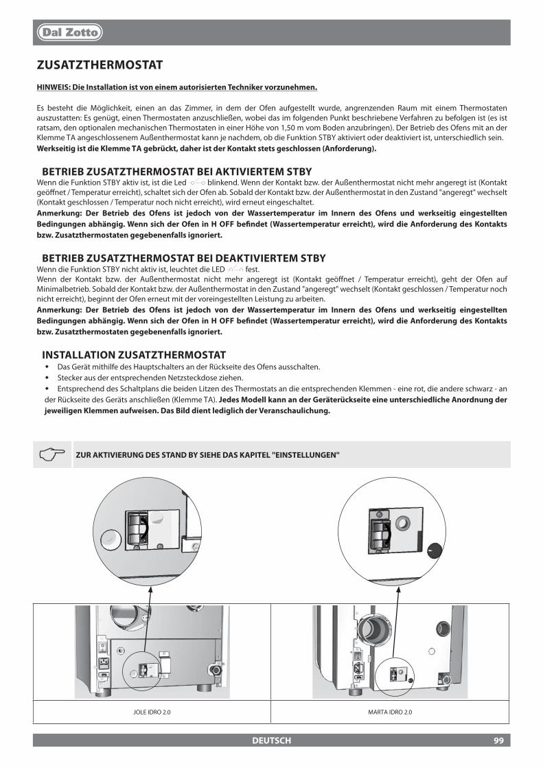
JOLE IDRO 2.0 MARTA IDRO 2.0
DEUTSCH
ZUSATZTHERMOSTAT
HINWEIS: Die Installation ist von einem autorisierten Techniker vorzunehmen.
Es besteht die Möglichkeit, einen an das Zimmer, in dem der Ofen aufgestellt wurde, angrenzenden Raum mit einem Thermostaten auszustatten: Es genügt, einen Thermostaten anzuschließen, wobei das im folgenden Punkt beschriebene Verfahren zu befolgen ist (es ist ratsam, den optionalen mechanischen Thermostaten in einer Höhe von 1,50 m vom Boden anzubringen). Der Betrieb des Ofens mit an der Klemme TA angeschlossenem Außenthermostat kann je nachdem, ob die Funktion STBY aktiviert oder deaktiviert ist, unterschiedlich sein.Werkseitig ist die Klemme TA gebrückt, daher ist der Kontakt stets geschlossen (Anforderung).
BETRIEB ZUSATZTHERMOSTAT BEI AKTIVIERTEM STBYWenn die Funktion STBY aktiv ist, ist die Led blinkend. Wenn der Kontakt bzw. der Außenthermostat nicht mehr angeregt ist (Kontakt geö�net / Temperatur erreicht), schaltet sich der Ofen ab. Sobald der Kontakt bzw. der Außenthermostat in den Zustand "angeregt" wechselt (Kontakt geschlossen / Temperatur noch nicht erreicht), wird erneut eingeschaltet.Anmerkung: Der Betrieb des Ofens ist jedoch von der Wassertemperatur im Innern des Ofens und werkseitig eingestellten Bedingungen abhängig. Wenn sich der Ofen in H OFF be�ndet (Wassertemperatur erreicht), wird die Anforderung des Kontakts bzw. Zusatzthermostaten gegebenenfalls ignoriert.
BETRIEB ZUSATZTHERMOSTAT BEI DEAKTIVIERTEM STBYWenn die Funktion STBY nicht aktiv ist, leuchtet die LED fest.Wenn der Kontakt bzw. der Außenthermostat nicht mehr angeregt ist (Kontakt geö�net / Temperatur erreicht), geht der Ofen auf Minimalbetrieb. Sobald der Kontakt bzw. der Außenthermostat in den Zustand "angeregt" wechselt (Kontakt geschlossen / Temperatur noch nicht erreicht), beginnt der Ofen erneut mit der voreingestellten Leistung zu arbeiten. Anmerkung: Der Betrieb des Ofens ist jedoch von der Wassertemperatur im Innern des Ofens und werkseitig eingestellten Bedingungen abhängig. Wenn sich der Ofen in H OFF be�ndet (Wassertemperatur erreicht), wird die Anforderung des Kontakts bzw. Zusatzthermostaten gegebenenfalls ignoriert.
INSTALLATION ZUSATZTHERMOSTAT� Das Gerät mithilfe des Hauptschalters an der Rückseite des Ofens ausschalten.� Stecker aus der entsprechenden Netzsteckdose ziehen.� Entsprechend des Schaltplans die beiden Litzen des Thermostats an die entsprechenden Klemmen - eine rot, die andere schwarz - an der Rückseite des Geräts anschließen (Klemme TA). Jedes Modell kann an der Geräterückseite eine unterschiedliche Anordnung der jeweiligen Klemmen aufweisen. Das Bild dient lediglich der Veranschaulichung.
J
ZUR AKTIVIERUNG DES STAND BY SIEHE DAS KAPITEL ''EINSTELLUNGEN''
99
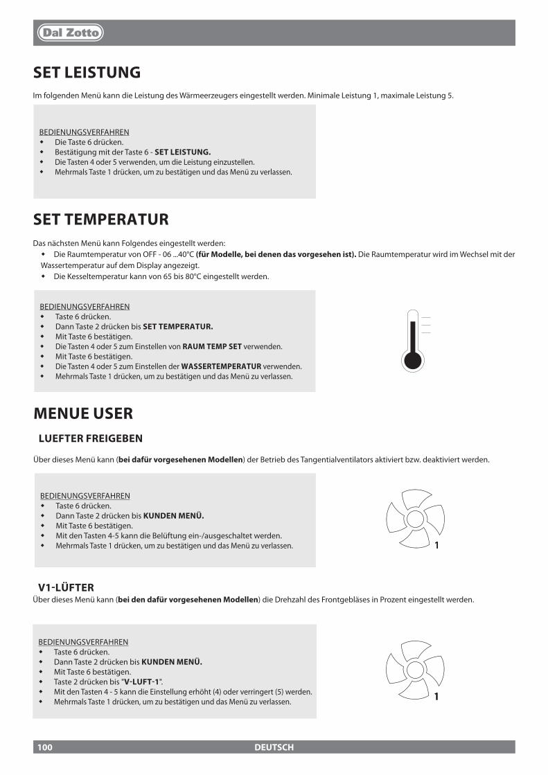
DEUTSCH
SET LEISTUNGIm folgenden Menü kann die Leistung des Wärmeerzeugers eingestellt werden. Minimale Leistung 1, maximale Leistung 5.
BEDIENUNGSVERFAHREN� Die Taste 6 drücken.� Bestätigung mit der Taste 6 - SET LEISTUNG.� Die Tasten 4 oder 5 verwenden, um die Leistung einzustellen.� Mehrmals Taste 1 drücken, um zu bestätigen und das Menü zu verlassen.
SET TEMPERATURDas nächsten Menü kann Folgendes eingestellt werden:� Die Raumtemperatur von OFF - 06 ...40°C (für Modelle, bei denen das vorgesehen ist). Die Raumtemperatur wird im Wechsel mit der Wassertemperatur auf dem Display angezeigt.� Die Kesseltemperatur kann von 65 bis 80°C eingestellt werden.
BEDIENUNGSVERFAHREN� Taste 6 drücken.� Dann Taste 2 drücken bis SET TEMPERATUR.� Mit Taste 6 bestätigen.� Die Tasten 4 oder 5 zum Einstellen von RAUM TEMP SET verwenden.� Mit Taste 6 bestätigen.� Die Tasten 4 oder 5 zum Einstellen der WASSERTEMPERATUR verwenden.� Mehrmals Taste 1 drücken, um zu bestätigen und das Menü zu verlassen.
MENUE USERLUEFTER FREIGEBEN
Über dieses Menü kann (bei dafür vorgesehenen Modellen) der Betrieb des Tangentialventilators aktiviert bzw. deaktiviert werden.
BEDIENUNGSVERFAHREN� Taste 6 drücken.� Dann Taste 2 drücken bis KUNDEN MENÜ.� Mit Taste 6 bestätigen.� Mit den Tasten 4-5 kann die Belüftung ein-/ausgeschaltet werden. � Mehrmals Taste 1 drücken, um zu bestätigen und das Menü zu verlassen. 1
V1-LÜFTERÜber dieses Menü kann (bei den dafür vorgesehenen Modellen) die Drehzahl des Frontgebläses in Prozent eingestellt werden.
BEDIENUNGSVERFAHREN� Taste 6 drücken.� Dann Taste 2 drücken bis KUNDEN MENÜ.� Mit Taste 6 bestätigen.� Taste 2 drücken bis "V-LUFT-1".� Mit den Tasten 4 - 5 kann die Einstellung erhöht (4) oder verringert (5) werden. � Mehrmals Taste 1 drücken, um zu bestätigen und das Menü zu verlassen. 1
100

DEUTSCH
BEDIENUNGSVERFAHREN� Taste 6 drücken.� Dann Taste 2 drücken bis KUNDEN MENÜ.� Mit Taste 6 bestätigen.� Taste 2 drücken bis RESET.� Mit den Tasten 4-5 ON einstellen und die Taste 6 drücken.� Zur Bestätigung wird "ERLEDIGT" im Display angezeigt
EASY SET UPDas volumetrische Gewicht des Pellets ist das Verhältnis zwischen dem Gewicht und dem Volumen des Pellets. Dieses Verhältnis kann sich bei gleichbleibender Qualität des Pellets ändern. Unter Verwendung der Funktion EASY SET UP hat man die Möglichkeit, die Eichung des volumetrischen Gewichts durch Erhöhung oder Verringerung der voreingestellten Werte zu ändern.Die im Programm des Ofens verfügbaren Werte gehen von “– 3” bis “+ 3”; alle Öfen werden bei der Produktion mit dem optimalen Wert, der 0 beträgt, geeicht.Wenn eine übermäßige Ablagerung in der Brennschale festgestellt werden sollte, emp�ehlt man, im Programm EASY SET UP den Wert um eine Einheit auf “- 1” zu senken; warten Sie den folgenden Tag ab und falls keine Verbesserung eintreten sollte, weiterhin bis zu maximal “- 3” senken. Im Falle, dass sich stattdessen die Notwendigkeit ergeben sollte, die Eichung des volumetrischen Gewichts des Pellets zu erhöhen, wird empfohlen, vom Wert der Werkeinstellung “0” auf “+ 1, + 2, + 3”, je nach Bedarf, überzugehen
RESET
Hiermit können alle vom Benutzer einstellbaren Werte auf Werkseinstellung zurückgebracht werden.
ÜBERMÄSSIGE ABLAGERUNG VON PELLETS IN DER BRENNSCHALE
NORMALE FUNKTIONSWEISE
GERINGE ABLAGERUNG VON PELLETS IN DER BRENNSCHALE
-3 -2 -1 0 +1 +2 +3
DRITTER BEREICH DER VERRINGE-
RUNG, FALLS DIE ERSTEN BEIDEN NICHT AUSREI-
CHEND SEIN SOLLTEN
ZWEITER BEREICH DER VERRINGE-
RUNG, FALLS DER ERSTE NICHT
AUSREICHEND SEIN SOLLTE
ERSTER BEREICH DER VERRINGE-
RUNG (FÜR 1 TAG TESTEN)
OPTIMALER WERKEIN-STELLUNGSWERT
ERSTER BEREICH DER ERHÖHUNG
ZWEITER BEREICH DER ERHÖHUNG, FALLS DER ERSTE
NICHT AUSREI-CHEND SEIN
SOLLTE
DRITTER BEREICH DER ERHÖHUNG,
FALLS DIE ERSTEN BEIDEN NICHT AUSREICHEND SEIN SOLLTEN
SET CHRONOMit dieser Funktion kann die Ein- und Ausschaltung des Wärmeerzeugers automatisch programmiert werden.Werkseitig ist bei den Wärmeerzeugern SET CHRONO deaktiviert.Die Chrono-Funktion ermöglicht die Programmierung von 4 Zeitspannen innerhalb eines Tages, die für alle Wochentage zu benutzen sind. In jeder Zeitspanne können die Ein- und Ausschaltzeit, die Tage zur Benutzung der programmierten Zeitspanne und die gewünschte Wassertemperatur (65 - 80 °C) eingestellt werden. Die Einstellung des Tags und der Uhrzeit ist grundlegend für den korrekten Betrieb der Chrono-Funktion.
EMPFEHLUNGENVor Benutzung der Chrono-Funktion müssen Tag und laufende Uhrzeit eingestellt werden. Daher ist zu prüfen, ob die Schritte im Unterkapitel "Set Uhr" durchgeführt wurden, damit die Chrono-Funktion arbeitet, muss sie nicht nur programmiert, sondern auch aktiviert werden. Die Ein- und Ausschaltzeiten müssen im Lauf eines einzigen Tags, von 0 bis 24 Uhr, enthalten sein und dürfen nicht auf mehr Tage fallen.
RICHTIG FALSCH
Einschaltung um 07:00 UhrAusschaltung um 18:00 Uhr
Einschaltung um 22:00 UhrAusschaltung um 05:00 Uhr
Beispiel:
ANM.: Im Falle, dass diese Eichungen die Anwesenheit der Ablagerungen der Pellets in der Brennschale nicht lösen sollten, bittet man, Kontakt mit dem nächstliegenden Kundendienstzentrum aufzunehmen.
PROZEDUR STEUERUNGEN� Die Taste 6 drücken.� Mit dem Druck der Taste 2 bis zum KUNDEN MENÜ.� Mit der Taste 6 bestätigen.� Die Taste 2 bis zu "EASY SET UP" drücken.� Die Tasten 4 -5 verwenden, um das Laden während der Phase BETRIEB zu erhöhen (4) oder zu verringern (5).� Die Taste 1 mehrmals drücken, um zu bestätigen und das Menü zu verlassen.
101

DEUTSCH
JWENN DER WOCHENPROGRAMMIERER AKTIVIERT IST, GEHT AUF DER BEDIENTAFEL EIN KLEINES QUADRAT DES ENTSPRECHENDEN SYMBOLS AN.
DISPLAY EINSTELLUNG BEDEUTUNG
SET CHRONO AKTIVIERUNG CHRONO On/o� Aktiviert/deaktiviert die ganze Einstellung von Chrono
FREIGABE PRG1 On/o� Aktiviert/deaktiviert das PRG1
FREIGABE PRG2 On/o� Aktiviert/deaktiviert das PRG2
FREIGABE PRG3 On/o� Aktiviert/deaktiviert das PRG3
FREIGABE PRG4 On/o� Aktiviert/deaktiviert das PRG4
START PRG1 OFF-00:00-23:50 Einschaltzeit PRG1
STOP PRG1 OFF-00:00-23:50 Ausschaltzeit PRG1
MONTAG...SONNTAG On/o� Aktiviert/deaktiviert die Tage von PRG1
SET PRG1 65-80°c Heizkessel-Temperatur von PRG1
START PRG2 OFF-00:00-23:50 Einschaltzeit PRG2
STOP PRG2 OFF-00:00-23:50 Ausschaltzeit PRG2
MONTAG...SONNTAG On/o� Aktiviert/deaktiviert die Tage von PRG2
SET PRG2 65-80°c Heizkessel-Temperatur von PRG2
START PRG3 OFF-00:00-23:50 Einschaltzeit PRG3
STOP PRG3 OFF-00:00-23:50 Ausschaltzeit PRG3
MONTAG...SONNTAG On/o� Aktiviert/deaktiviert die Tage von PRG3
SET PRG3 65-80°c Heizkessel-Temperatur von PRG3
START PRG4 OFF-00:00-23:50 Einschaltzeit PRG4
STOP PRG4 OFF-00:00-23:50 Ausschaltzeit PRG4
MONTAG...SONNTAG On/o� Aktiviert/deaktiviert die Tage von PRG4
SET PRG4 65-80°c Heizkessel-Temperatur von PRG4
BEDIENUNGSVERFAHREN� Taste 6 drücken.� Dann Taste 2 drücken bis SET CHRONO.� Mit Taste 6 bestätigen.� Mit den Tasten 4 - 5 die Uhrzeit aktivieren/deaktivieren - einstellen/ändern.� Taste 2 drücken, um vorwärts zu gehen, Taste 3 für zurück.� Mehrmals Taste 1 drücken, um zu bestätigen und das Menü zu verlassen.
STATUSDem Techniker vorbehaltene Hinweise
EINSTELLUNGENSET UHR EINSTELLUNG DER SPRACHE
� siehe Kapitel: Einstellungen erste Inbetriebnahme
DISPLAY
Das Menü "DISPLAY" hat zwei Untermenüs:� Tastensperre� Helligkeit.
102
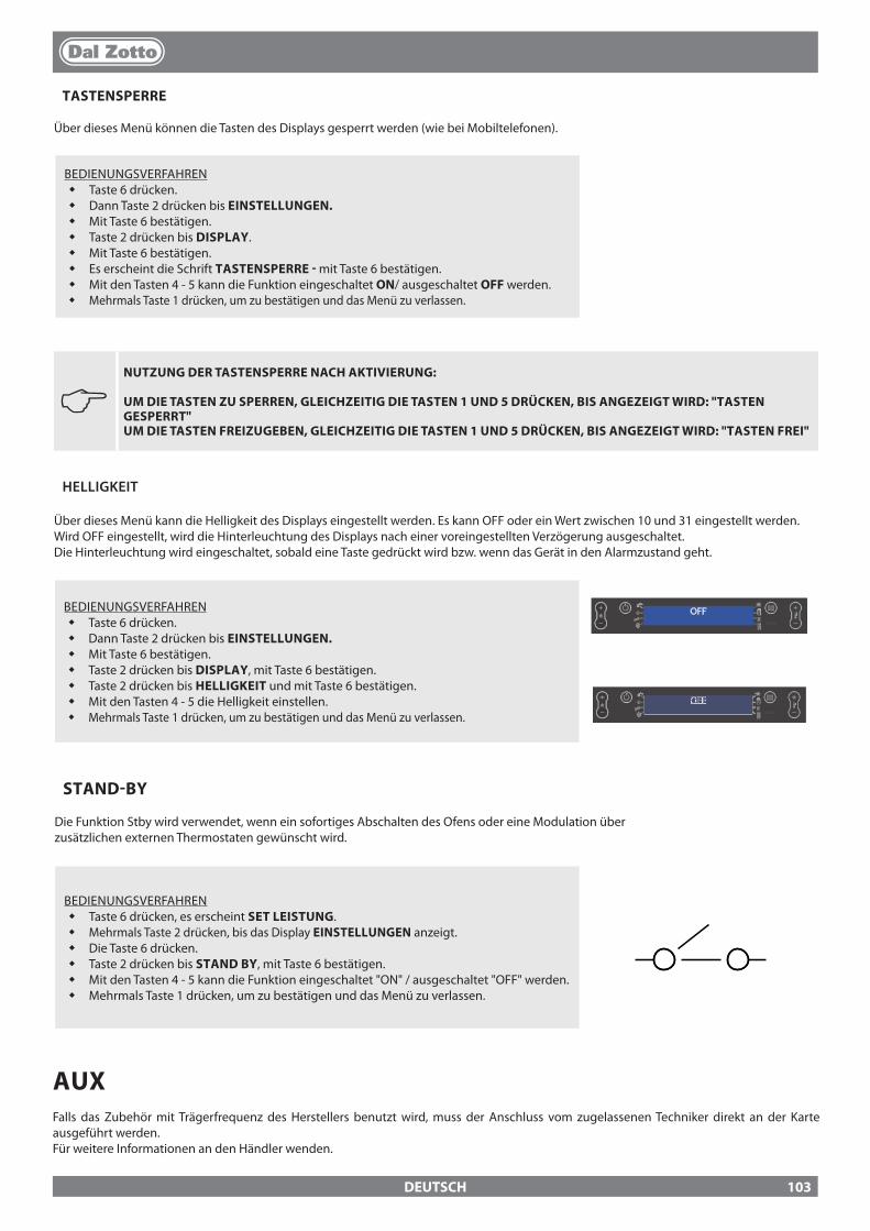
DEUTSCH
J NUTZUNG DER TASTENSPERRE NACH AKTIVIERUNG:
UM DIE TASTEN ZU SPERREN, GLEICHZEITIG DIE TASTEN 1 UND 5 DRÜCKEN, BIS ANGEZEIGT WIRD: "TASTEN GESPERRT" UM DIE TASTEN FREIZUGEBEN, GLEICHZEITIG DIE TASTEN 1 UND 5 DRÜCKEN, BIS ANGEZEIGT WIRD: "TASTEN FREI"
HELLIGKEIT
Über dieses Menü kann die Helligkeit des Displays eingestellt werden. Es kann OFF oder ein Wert zwischen 10 und 31 eingestellt werden.Wird OFF eingestellt, wird die Hinterleuchtung des Displays nach einer voreingestellten Verzögerung ausgeschaltet. Die Hinterleuchtung wird eingeschaltet, sobald eine Taste gedrückt wird bzw. wenn das Gerät in den Alarmzustand geht.
BEDIENUNGSVERFAHREN� Taste 6 drücken.� Dann Taste 2 drücken bis EINSTELLUNGEN.� Mit Taste 6 bestätigen.� Taste 2 drücken bis DISPLAY, mit Taste 6 bestätigen.� Taste 2 drücken bis HELLIGKEIT und mit Taste 6 bestätigen.� Mit den Tasten 4 - 5 die Helligkeit einstellen.� Mehrmals Taste 1 drücken, um zu bestätigen und das Menü zu verlassen.
OFF
OFF
TASTENSPERRE
Über dieses Menü können die Tasten des Displays gesperrt werden (wie bei Mobiltelefonen).
BEDIENUNGSVERFAHREN� Taste 6 drücken.� Dann Taste 2 drücken bis EINSTELLUNGEN.� Mit Taste 6 bestätigen.� Taste 2 drücken bis DISPLAY.� Mit Taste 6 bestätigen.� Es erscheint die Schrift TASTENSPERRE - mit Taste 6 bestätigen.� Mit den Tasten 4 - 5 kann die Funktion eingeschaltet ON/ ausgeschaltet OFF werden.� Mehrmals Taste 1 drücken, um zu bestätigen und das Menü zu verlassen.
STAND-BY
Die Funktion Stby wird verwendet, wenn ein sofortiges Abschalten des Ofens oder eine Modulation über zusätzlichen externen Thermostaten gewünscht wird.
BEDIENUNGSVERFAHREN� Taste 6 drücken, es erscheint SET LEISTUNG.� Mehrmals Taste 2 drücken, bis das Display EINSTELLUNGEN anzeigt.� Die Taste 6 drücken.� Taste 2 drücken bis STAND BY, mit Taste 6 bestätigen.� Mit den Tasten 4 - 5 kann die Funktion eingeschaltet "ON" / ausgeschaltet "OFF" werden.� Mehrmals Taste 1 drücken, um zu bestätigen und das Menü zu verlassen.
AUXFalls das Zubehör mit Trägerfrequenz des Herstellers benutzt wird, muss der Anschluss vom zugelassenen Techniker direkt an der Karte ausgeführt werden.Für weitere Informationen an den Händler wenden.
103

DEUTSCH
REINIGUNG UND WARTUNGDIE ANWEISUNGEN IMMER IN GRÖSSTMÖGLICHER SICHERHEIT AUSFÜHREN!
Sicherstellen, dass der Stecker des Stromversorgungskabels abgezogen ist, da der Generator so programmiert sein könnte, dass er sich einschaltet. Der Generator überall kalt ist.Die Asche vollständig abgekühlt ist.Während der Reinigungsarbeiten des Produktes einen wirkungsvollen Luftaustausch des Raumes garantieren.Eine schlechte Reinigung beeinträchtigt den korrekten Betrieb und die Sicherheit!
WARTUNGFür einen einwandfreien Betrieb muss am Generator mindestens einmal im Jahr eine ordentliche Wartung durch einen zugelassenen Techniker vorgenommen werden.Die regelmäßigen Kontroll- und Wartungseingri�e müssen immer von zugelassenen Fachtechnikern ausgeführt werden, die gemäß den gültigen Vorschriften und den Anweisungen in dieser Gebrauchs- und Wartungsanleitung arbeiten.
TÄGLICH Brennschale: Brennschale aus dem Fach nehmen und die Löcher frei machen, dazu den mitgelieferten Schürhaken verwenden, Asche mit einem Staubsauger aus der Brennschale entfernen. Die im Fach der Brennschale abgelagerte Asche und Reinigung Rohrs der Zündelement absaugen.
DIE RAUCHABLASSANLAGE, DIE RAUCHLEITUNGEN UND DIE "T"-VERBINDUNGSSTÜCKE SOWIE DIE INSPEKTIONSABDECKUNGEN UND - FALLS VORHANDEN BIEGUNGEN UND HORIZONTALE ABSCHNITTE - MÜSSEN JEDES JAHR GEREINIGT WERDEN.DIE HÄUFIGKEITSANGABEN DER REINIGUNG DES GENERATORS SIND RICHTWERTE! DIESE HÄNGEN VON DER QUALITÄT DER VERWENDETEN PELLETS UND VON DER HÄUFIGKEIT DER ANWENDUNG AB. ES KANN SEIN, DASS DIESE ARBEITEN HÄUFIGER AUSGEFÜHRT WERDEN MÜSSEN.
REGELMÄSSIGE VOM BENUTZER AUSZUFÜHRENDE REINIGUNG
Die regelmäßigen Reinigungsarbeiten müssen gemäß Angabe in dieser Gebrauchs- und Wartungsanleitung mit maximaler Sorgfalt ausgeführt werden, nachdem die Anweisungen, Verfahren und Zeiten, die in dieser Gebrauchs- und Wartungsanleitung beschrieben werden, durchgelesen wurden.
REINIGUNG DER OBERFLÄCHEN UND DER VERKLEIDUNG
Nie abrasive ODER CHEMISCHE AGGRESSIVE REINIGUNGSMITTEL für die Reinigung benutzen!Die Reinigung der Ober�ächen darf erst erfolgen, wenn der Generator und die Verkleidung vollkommen kalt sind. Für die P�ege der Ober�ächen und der Metallteile genügt ein mit Wasser oder mit Wasser und neutraler Seife angefeuchtetes Tuch.Die Nichtbeachtung der Anleitungen kann die Ober�ächen des Generators beschädigen und zum Verfall der Garantie führen.
REINIGUNG DES KERAMIKGLASES
Nie abrasive ODER CHEMISCHE AGGRESSIVE REINIGUNGSMITTEL für die Reinigung benutzen!Die Reinigung des Keramikglases darf nur bei vollkommen kaltem Glas erfolgen. Zur Reinigung des Keramikglases genügt ein trockener Pinsel und ANGEFEUCHTETES UND DURCH ASCHE GEZOGENES ZEITUNGSPAPIER (TAGESZEITUNG). Bei sehr stark verschmutztem Glas darf nur ein spezi�sches Reinigungsmittel für Keramikgläser verwendet werden. Eine geringe Menge auf ein Tuch sprühen, und das Keramikglas mit diesem abwischen. Das Reinigungsmittel oder sonstige Flüssigkeiten nicht direkt auf das Glas oder die Dichtungen sprühen!Die Nichtbeachtung der Anleitungen kann die Ober�äche des Keramikglases beschädigen und zum Verfall der Garantie führen.
REINIGUNG DES PELLETBEHÄLTERS
Ist der Behälter vollkommen entleert, das Stromversorgungskabel des Generators abziehen, und vor dem Au�üllen zuerst die Rückstände (Staub, Späne usw.) aus dem leeren Behälter entfernen.
104
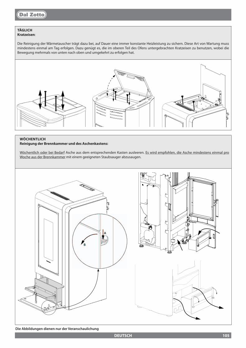
DEUTSCH
TÄGLICHKratzeisen:
Die Reinigung der Wärmetauscher trägt dazu bei, auf Dauer eine immer konstante Heizleistung zu sichern. Diese Art von Wartung muss mindestens einmal am Tag erfolgen. Dazu genügt es, die im oberen Teil des Ofens untergebrachten Kratzeisen zu benutzen, wobei die Bewegung mehrmals von unten nach oben und umgekehrt zu erfolgen hat.
WÖCHENTLICH Reinigung der Brennkammer und des Aschenkastens:
Wöchentlich oder bei Bedarf Asche aus dem entsprechenden Kasten ausleeren. Es wird empfohlen, die Asche mindestens einmal pro Woche aus der Brennkammer mit einem geeigneten Staubsauger abzusaugen.
Die Abbildungen dienen nur der Veranschaulichung
105

DEUTSCH
WENN DAS STROMVERSORGUNGSKABEL BESCHÄDIGT IST, MUSS ES DURCH DEN KUNDENDIENST ODER EINE PERSON MIT GLEICHARTIGER BEFÄHIGUNG AUSGEWECHSELT WERDEN, UM JEDE GEFAHR ZU VERMEIDEN.
MONATLICH - JOLE IDRO 2.0
Die im oberen Teil der Feuerraumwand abgelagerte Asche entfernen (siehe Abbildung unten).
VON ZUGELASSENEN FACHTECHNIKERN AUSGEFÜHRTE FACHMÄNNISCHE WARTUNGDie fachmännische Wartung muss mindestens einmal jährlich ausgeführt werden.Da für den Wärmeerzeuger Pellets als fester Brennsto� verwendet werden, ist ein jährlicher ordentlicher Wartungseingri� notwendig, der von einem zugelassenen Techniker oder einem werksmäßig geschulten Wartungstechniker ihres Händlers ausgeführt werden muss, wobei ausschließlich Originalersatzteile ver-wendet werden dürfen.Die Nichtbeachtung kann die Sicherheit des Geräts beeinträchtigen und das Recht auf die Garantiebedingungen verwirken.Durch die Beachtung der Reinigungshäu�gkeit, die dem Benutzer vorbehalten ist und die in der Gebrauchs- und Wartungsanleitung beschrieben wird, wird eine korrekte Verbrennung des Generators im Laufe der Zeit garantiert, und es werden eventuelle Anomalien und/oder Störungen verhindert, die größere Eingri�e des Technikers erfordern könnten. Die Anfragen für ordentliche Wartungseingri�e sind nicht in der Garantie des Produkts vorgesehen.
DICHTUNGEN VON TÜR, ASCHENKASTEN UND BRENNSCHALEDie Dichtungen gewährleisten die hermetische Dichtheit des Ofens und folglich dessen einwandfreien Betrieb.Sie müssen periodisch kontrolliert werden: bei Verschleiß oder Beschädigungen müssen sie sofort ersetzt werden Anschluss am SchornsteinEinmal im Jahr bzw. jedes Mal, wenn dies notwendig ist, muss das Rohr zum Schornstein ausgesaugt und gesäubert werden. Wenn waagerechte Rohrabschnitte vorhanden sind, müssen sie von Rückständen befreit werden, bevor diese die Abgasströmung behindern.
RAUCHROHRANSCHLUSS AN DEN SCHORNSTEINJährlich oder jedenfalls immer, wenn sich die Notwendigkeit ergibt, ist die zum Schornstein führende Rohrlei-tung absaugen und reinigen. Wenn waagrechte Abschnitte vorhanden sind, müssen die Rückstände entfernt werden, bevor diese den Durchgang der Rauchgase verstopfen.
AUSSERBETRIEBNAHME (SAISONENDE)Bei jedem Saisonende wird vor der Ausschaltung des Ofens empfohlen, den Pelletbehälter vollständig zu ent-leeren und alle Rückstände von Pellets und Staub aus einem Inneren abzusaugen. WIR EMPFEHLEN IHNEN DEN GENERATOR NICHT VOM STROMVERSORGUNGSNETZ ZU TRENNEN, DAMIT DER ZIRKULATOR DIE NORMALEN ANTIBLOCKIER-ZYKLEN AUSFÜHREN KANN.Außerdem wird dazu aufgefordert, den Wärmeerzeuger für eine höhere Sicherheit, vor allem wenn Kinder anwesend sind, vom Stromnetz zu trennen und das Stromversorgungskabel zu entfernen.
106
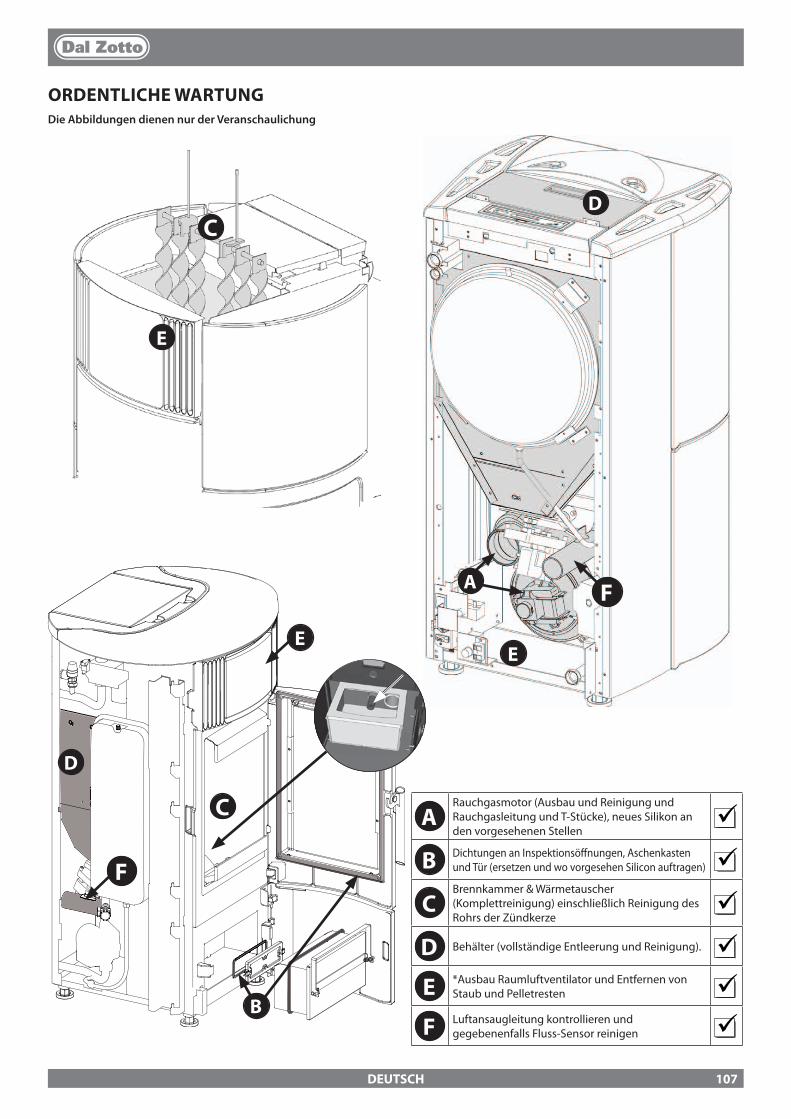
B
E
D
C
A
C
F
D
EE
F
DEUTSCH
ORDENTLICHE WARTUNGDie Abbildungen dienen nur der Veranschaulichung
ARauchgasmotor (Ausbau und Reinigung und Rauchgasleitung und T-Stücke), neues Silikon an den vorgesehenen Stellen
B Dichtungen an Inspektionsö�nungen, Aschenkasten und Tür (ersetzen und wo vorgesehen Silicon auftragen)
CBrennkammer & Wärmetauscher (Komplettreinigung) einschließlich Reinigung des Rohrs der Zündkerze
D Behälter (vollständige Entleerung und Reinigung). E *Ausbau Raumluftventilator und Entfernen von
Staub und Pelletresten F Luftansaugleitung kontrollieren und
gegebenenfalls Fluss-Sensor reinigen
107
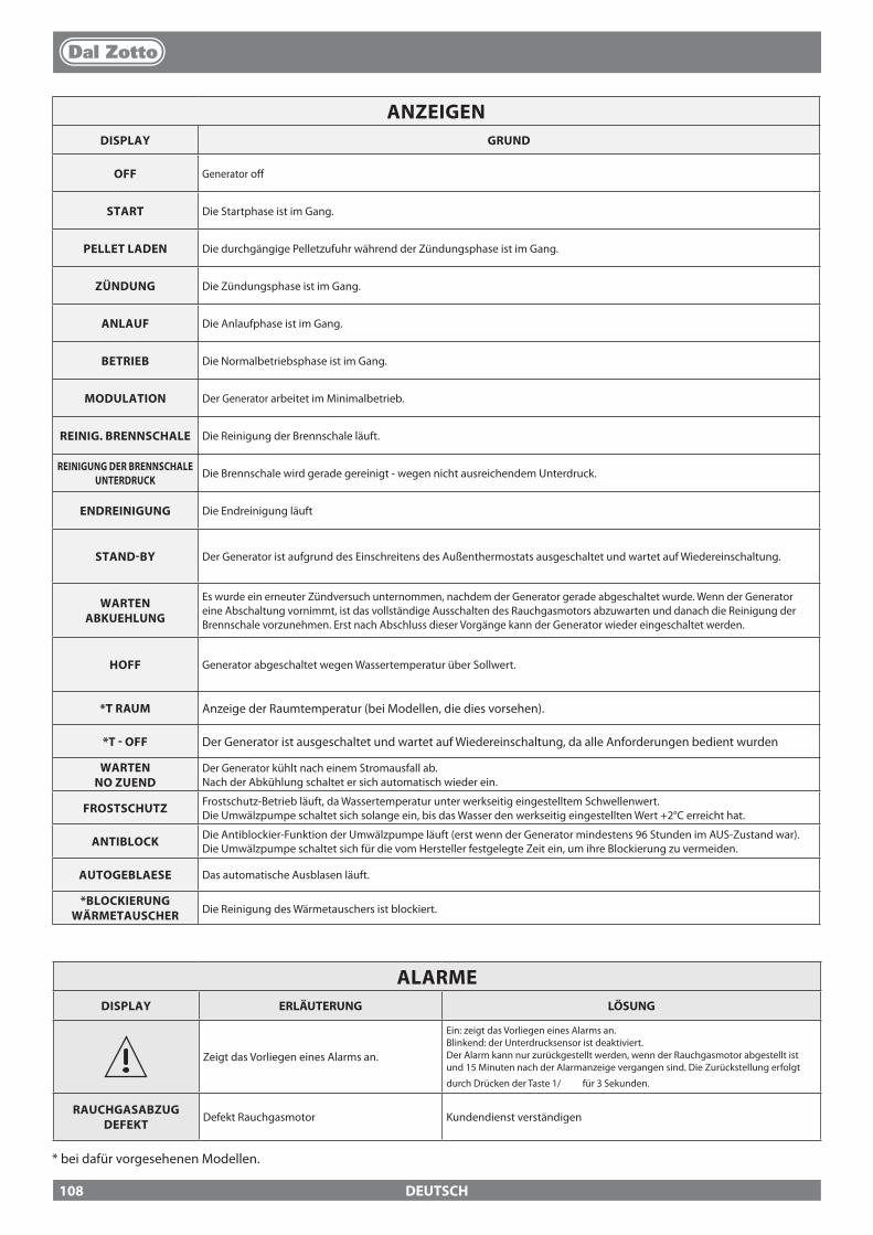
DEUTSCH
ANZEIGENDISPLAY GRUND
OFF Generator o�
START Die Startphase ist im Gang.
PELLET LADEN Die durchgängige Pelletzufuhr während der Zündungsphase ist im Gang.
ZÜNDUNG Die Zündungsphase ist im Gang.
ANLAUF Die Anlaufphase ist im Gang.
BETRIEB Die Normalbetriebsphase ist im Gang.
MODULATION Der Generator arbeitet im Minimalbetrieb.
REINIG. BRENNSCHALE Die Reinigung der Brennschale läuft.
REINIGUNG DER BRENNSCHALEUNTERDRUCK Die Brennschale wird gerade gereinigt - wegen nicht ausreichendem Unterdruck.
ENDREINIGUNG Die Endreinigung läuft
STAND-BY Der Generator ist aufgrund des Einschreitens des Außenthermostats ausgeschaltet und wartet auf Wiedereinschaltung.
WARTEN ABKUEHLUNG
Es wurde ein erneuter Zündversuch unternommen, nachdem der Generator gerade abgeschaltet wurde. Wenn der Generator eine Abschaltung vornimmt, ist das vollständige Ausschalten des Rauchgasmotors abzuwarten und danach die Reinigung der Brennschale vorzunehmen. Erst nach Abschluss dieser Vorgänge kann der Generator wieder eingeschaltet werden.
HOFF Generator abgeschaltet wegen Wassertemperatur über Sollwert.
*T RAUM Anzeige der Raumtemperatur (bei Modellen, die dies vorsehen).
*T - OFF Der Generator ist ausgeschaltet und wartet auf Wiedereinschaltung, da alle Anforderungen bedient wurden
WARTEN NO ZUEND
Der Generator kühlt nach einem Stromausfall ab. Nach der Abkühlung schaltet er sich automatisch wieder ein.
FROSTSCHUTZ Frostschutz-Betrieb läuft, da Wassertemperatur unter werkseitig eingestelltem Schwellenwert.Die Umwälzpumpe schaltet sich solange ein, bis das Wasser den werkseitig eingestellten Wert +2°C erreicht hat.
ANTIBLOCK Die Antiblockier-Funktion der Umwälzpumpe läuft (erst wenn der Generator mindestens 96 Stunden im AUS-Zustand war). Die Umwälzpumpe schaltet sich für die vom Hersteller festgelegte Zeit ein, um ihre Blockierung zu vermeiden.
AUTOGEBLAESE Das automatische Ausblasen läuft.
*BLOCKIERUNG WÄRMETAUSCHER Die Reinigung des Wärmetauschers ist blockiert.
ALARMEDISPLAY ERLÄUTERUNG LÖSUNG
Zeigt das Vorliegen eines Alarms an.
Ein: zeigt das Vorliegen eines Alarms an.Blinkend: der Unterdrucksensor ist deaktiviert.Der Alarm kann nur zurückgestellt werden, wenn der Rauchgasmotor abgestellt ist und 15 Minuten nach der Alarmanzeige vergangen sind. Die Zurückstellung erfolgt
durch Drücken der Taste 1/ für 3 Sekunden.
RAUCHGASABZUG DEFEKT
Defekt Rauchgasmotor Kundendienst verständigen
* bei dafür vorgesehenen Modellen.
108

DEUTSCH
* bei dafür vorgesehenen Modellen.
RAUCHSONDE Defekt Rauchgassonde. Kundendienst verständigen
RAUCH HEISS Rauchgastemperatur sehr hoch Pelletzufuhr kontrollieren (siehe "Einstellung der Pelletzufuhr"), bei Fortbestehen zugelassenen Techniker verständigen.
ALARM CLEAN CHECK UP
Die Tür ist nicht richtig geschlossen.Der Aschenkasten ist nicht richtig geschlossen.Die Brennkammer ist verschmutzt.Die Rauchabzugsleitung ist verstopft.
Überprüfen, ob die Tür hermetisch schließt.Überprüfen, ob der Aschenkasten hermetisch schließt.Sauberkeit der Rauchgasleitung, des Sensors im Primärluftkanal und der Brennkammer überprüfen.
FEHL- ZÜNDUNG
Der Pelletbehälter ist leer.Ungeeignete Einstellung der Pelletzufuhr.Kapillarrohrthermostaten ausgelöst.
Überprüfen, ob Pellets im Behälter vorhanden sind, oder nicht.Pelletzufuhr regulieren (siehe “Einstellung der Pelletzufuhr”).Kontrollieren, ob die im Kapitel "Zündung" beschriebenen Verfahren eingehalten werden.Kapillarrohrthermostaten prüfen (siehe Kapitel Rücksetzung)
STROMAUSF. NO ZUEND
Stromausfall während der Zündungsphase. Den Ofen mit Taste 1 auf OFF bringen und die im Kapitel "Zündung" beschriebenen Verfahren wiederholen.
PELLETMANGEL Der Pelletbehälter ist leer.Ungenügende Pelletzufuhr.Der Getriebemotor führt keine Pellets zu.
Überprüfen, ob Pellets im Behälter vorhanden sind, oder nicht.Pelletzufuhr regulieren (siehe “Einstellung der Pelletzufuhr”).
ALARM UNTERDRUCK:
Die Tür ist nicht richtig geschlossen.Der Aschenkasten ist nicht richtig geschlossen.Die Brennkammer ist verschmutzt.Die Rauchabzugsleitung ist verstopft/schmutzig.
Überprüfen, ob die Tür hermetisch schließt.Überprüfen, ob der Aschenkasten hermetisch schließt.Sauberkeit der Rauchgasleitung und der Brennkammer überprüfen.
U-DRUCKSONDE DEFEKT
Fluss-Sensor defekt.Sensoranschluss unterbrochen Kundendienst verständigen
WASSER-UEBERTEMPE-RATUR
Luft in der AnlageUngenügende Zirkulation
Möglicherweise ist Luft in der Anlage, Anlage entlüften.Ungenügende Zirkulation.Keine oder nicht angemessene Sicherheitszone.Die Wassertemperatur im Ofen hat 95 °C überschritten. Möglicherweise Störung der Umwälzpumpe.Bei Fortbestehen des Problems muss die Rücksetzung durch einen autorisierten Techniker ausgeführt werden.
* DEFEKT KLAPPE
Die automatische Reinigung der Brennschale ist blockiert. Schmutz verstopft die BrennschaleDie Tür ist nicht richtig geschlossen.
Überprüfen, ob die Tür richtig geschlossen istÜberprüfen, ob die Brennschale frei und sauber ist.Die automatische Reinigung der Brennschale ist blockiert.Falls das Problem anhält, den Kundendienst verständigen
ALARM H2O-DRUCK MIN
Der vom Druckwächter gemessene Anlagendruck ist zu niedrig.
Möglicherweise ist Luft in der Anlage, Anlage entlüften.Möglicherweise Wassermangel oder Verluste durch Störungen an einem Anlagenbauteil.Falls das Problem anhält, den Kundendienst verständigen
WASSER-SONDE Defekt der Wassersonde Kundendienst verständigen
ALARM H2O-DRUCK MAX
Der Wasserdruck hat den Maximal-Grenzwert überschritten.
Möglicherweise ist Luft in der Anlage, Anlage entlüften.Ausdehnungsgefäße prüfen, sie dürfen nicht beschädigt oder unterdimensioniert sein.Prüfen, ob die Anlage im kalten Zustand den richtigen Vordruck aufweist.Falls das Problem anhält, den Kundendienst verständigen
* DRUCKSENSOR DE-FEKT
Di�erentialdrucksensor defekt oder nicht angeschlossen.
Kundendienst verständigen
* STEUERUNG SCHNECKE Betriebsstörung der Pelletzufuhr. Kundendienst verständigen
* SCHNECKE BLOCKIERT Betriebsstörung des Pelletzufuhrmotors. Kundendienst verständigen
* SONDE BOILER Sonde Boiler defekt. Kundendienst verständigen
* PUFFER-SONDE Sonde Boiler defekt. Kundendienst verständigen
* BEHÄLTER LEER
Der Pelletbehälter ist leer. Die Tür ist nicht richtig geschlossen.Der Aschenkasten ist nicht richtig geschlossen.Die Brennkammer ist verschmutzt.Die Rauchabzugsleitung ist verstopft.
Überprüfen, ob Pellets im Behälter vorhanden sind, oder nicht.Überprüfen, ob die Tür hermetisch schließt.Überprüfen, ob der Aschenkasten hermetisch schließt.Sauberkeit der Rauchgasleitung, des Sensors im Primärluftkanal und der Brennkammer überprüfen.Kundendienst verständigen
109
DEUTSCH
1. Für alle DAL ZOTTO-Produkte, eine Handelsmarke der Firma La Nordica S.p.A., gewährleistet letztere innerhalb der Europäischen Gemeinschaft eine Garantie von 24 Monaten ab Kaufdatum. Das Kaufdatum muss durch ein steuerrechtlich gültiges Dokument des Verkäufers (Quittung, Rechnung oder Transportschein) belegt werden, aus dem das gekaufte Produkt, das Kaufdatum und die Lieferung ersichtlich sind.
ACHTUNG: Diese Herstellergarantie ist kein Ersatz für die von den europäischen Normen zum Schutz der Endabnehmer vorgeschriebenen Garantien.
Die Herstellergarantie beschränkt sich auf Italien und auf alle Gebiete der Europäischen Gemeinschaft, die vom technischen Kundendienstnetz des Herstellers gedeckt sind (nähere Informationen erhalten Sie über die Webseite www.dalzotto.com)Sie beschränkt sich außerdem auf das Land, indem der Verbraucher wohnhaft bzw. ansässig ist, unter der Bedingung, dass es sich um das gleiche Land handelt, in dem der Verkäufer des DAL ZOTTO-Produkts seinen Rechts- bzw. Geschäftssitz hat.Diese Bedingungen gelten nicht für den Fall, dass das Produkt zu gewerblichen, wirtschaftlichen oder Unternehmenszwecken benutzt wird. In diesen Fällen gilt die Garantie nur 12 Monate nach dem Verkaufsdatum.
GARANTIE FÜR ITALIENIm Falle eines Fehlbetriebs des Produkts zu tre�ende Maßnahmen: In der Betriebsanleitung prüfen, ob der Fehlbetrieb auf eine falsche Anwendung der Produktfunktionen zurückzuführen ist. Sicherstellen, dass der Defekt zu den Fehlern gehört, auf die sich die Garantie erstreckt. Andernfalls gehen die Reparaturkosten voll zu Lasten des Endabnehmers. Bei allen Anfragen an den technischen Kundendienst immer folgende Informationen mitteilen: - Fehlerbeschreibung - Gerätemodell - Genaue Adresse - Telefonnummer
GARANTIE FÜR EUROPAIm Falle eines Fehlbetriebs des Produkts zu tre�ende Maßnahmen: In der Betriebsanleitung prüfen, ob der Fehlbetrieb auf eine falsche Anwendung der Produktfunktionen zurückzuführen ist. Sicherstellen, dass der Defekt zu den Fehlern gehört, auf die sich die Garantie erstreckt. Andernfalls gehen die Reparaturkosten voll zu Lasten des Endabnehmers. Beantragen Sie einen Eingri� des technischen Kundendienst oder bitten Sie um die Anlage der technischen Kundendienststelle Ihres Händlers. Teilen Sie bei allen Anfragen folgende Informationen mit: Fehlerbeschreibung, Gerätemodell, genaue Adresse und Telefonnummer.
Für während der ersten 6 Monaten nach dem Verkauf des Produkts auftretende Konformitätsmängel hat der Endabnehmer Recht auf eine kostenlose Reparatur. Vom 7. bis zum 24. Monat wird bei Feststellung eines Konformitätsmangels dem Endabnehmer nur die Anfahrtsgebühr in Rechnung gestellt. Die Arbeitskosten und die Kosten für eventuelle Ersatzteile übernimmt weiterhin der Händler.
2. Sollte der beanstandete Defekt auf externe Bedingungen bzw. Ereignisse zurückzuführen sein, die wir hier anhand einiger nicht erschöpfenden Beispiele au�isten, kann keine Garantie übernommen werden: ungenügende Leistung der Anlage; falsche Installierung bzw. Wartung durch Personal, das nicht über die im Land des Wohnsitzes des Endabnehmers geltenden gesetzlichen Eigenschaften besitzt; Fahrlässigkeit; nicht vorschriftsmäßige Nutzung und mangelnde P�ege bzw. Nichtbeachtung von Bedienungsanleitung des Produkts, die Bestandteil des Verkaufsvertrags ist. Ebenso kann keine Garantie übernommen werden, wenn die Mängel am Produkt nicht auf bestimmte Ursachen aufgrund von Produktionsfehlern zurückzuführen sind. Der Garantieanspruch erlischt, wenn die Fehler auf einen unwirksamen Rauchabzug im Sinne des im Land des Händlers geltenden Gesetzes zurückzuführen sind, wenn das Produkt nicht mit der notwendigen Sorgfalt behandelt wurde, bei versehentlichen Schäden, Transportschäden (Kratzer, Beulen usw), wenn Reparaturen oder Eingri�e von Personen vorgenommen werden, die nicht ermächtigt sind oder wenn der Endabnehmer selber versucht, Reparaturen vorzunehmen. Für folgendes Verbrauchsmaterial wird keine Garantie gewährt: Dichtungen, keramische oder gehärtete Scheiben, Gusseisenverkleidungen und -gitter, feuerfeste Materialien (z.B. Nordiker o. Ä.), lackierte Teile, verchromte oder vergoldete Teile, Majolika, Gri�e, Kohlenbecken und entsprechende Bestandteile. Bei den Hydro-Produkten wird der Wärmeaustauscher nicht von der Garantie gedeckt, wenn nicht ein angemessener Kondensschutz-Kreislauf eingeplant wird, der eine Mindesttemperatur des Rücklaufs des Geräts von 55°C gewährleistet. Aus der Garantie ausgeschlossen sind ganz allgemein alle äußeren Komponenten des Produkts, auf die der Endabnehmer während des Einsatzes oder der Wartung direkt eingreifen kann, die einer Abnutzung bzw. Rostbildung ausgesetzt sind oder durch den Einsatz von aggressiven Reinigungsmitteln Flecken an den Stahlteilen aufweisen könnten. Im Falle von fehlerhaften Angaben über Defekte, die bei der Prüfung durch einen autorisierten Fachmann festgestellt werden, wird der Eingri� voll zu Lasten des Endabnehmers gehen.
3. Sollte es nicht möglich sein, die Konformität durch die Reparatur des Produkts bzw. der Komponente wieder herzustellen, ist ein Ersatz erforderlich. Dies beein�usst aber keinesfalls die Dauer der Garantie, deren Termin weiterhin ab Kaufdatum des ersetzten Produkts bzw. Teils gilt.
4. DAL ZOTTO, Handelsmarke der Firma La Nordica S.p.A., lehnt jede Verantwortung für etwaige Schäden ab, die, direkt oder indirekt, Personen, Tieren oder Gegenständen widerfahren könnten, welche auf die Nichtbeachtung aller in dieser Anleitung angeführten Anweisungen zurückzuführen sind und vor allem Hinweise in Sachen Installation, Gebrauch und Wartung des Geräts betre�en, die auch von unserer Webseite herunter geladen werden können.
GARANTIEBEDINGUNGEN
110
DEUTSCH
5. Nicht von der Garantie gedeckt sind Eingri�e für die Eichung bzw. Einstellung des Produkts in Bezug auf die Art des Brennsto�s o. ä.
6. Wird das Produkt in einer der von DAL ZOTTO autorisierten Kundendienststellen repariert und im Falle eines Ersatzes des Produkts, ist der Transport für den Endabnehmer kostenlos. Sollte der Fachmann imstande sein, das Produkt beim Sitz des Endabnehmers reparieren zu können, und sollte letzterer dies nicht zulassen, so gehend die Kosten für den Transport bis zur Reparaturwerkstatt und die Wiederzusendung zu seinen Lasten.
7. Nach Ablauf der 24-monatigen Garantie gehen alle Reparatureingri�e voll zu Lasten des Endabnehmers.
8. Für eventuelle Streitfragen ist ausschließlich das Gericht am Rechtssitz von DAL ZOTTO (Vicenza - Italien) zuständig.
WEITERE ANMERKUNGEN
� Nur vom Hersteller empfohlene Brennsto�e benutzen. Das Produkt darf nicht als Müllverbrennungsanlage missbraucht werden. � Das Produkt nicht als Treppe oder Abstell�äche verwenden. � Keine Wäsche zum Trocknen auf das Produkt legen. Wäscheständer oder ähnliche Gegenstände vom Produkt entfernt halten. Gefahr
eines Brandausfalls und einer Beschädigung der Verkleidung. � Der Endabnehmer trägt die ausschließliche Verantwortung für den unsachgemäßen Gebrauch des Produkts und entbindet somit den
Hersteller jeglicher zivil- und strafrechtlichen Haftung. � Jede Art des unsachgemäßen Eingri�s oder des nicht ermächtigten Austauschs durch nicht originale Bauteile des Produkts kann für die
Unversehrtheit des Endabnehmers gefährlich sein und enthebt den Hersteller von jeder zivil- und strafrechtlichen Verantwortung. � Der Großteil der Flächen des Produkts wird beim Betrieb sehr heiß (Tür, Handgri�, Glasscheibe, Rauchabgangsrohr usw.). Trägt man keine
sachgemäße Schutzkleidung oder verfügt man nicht über entsprechende Schutzmittel, wie zum Beispiel hitzebeständige Handschuhe, muss der Kontakt mit diesen Flächen unbedingt vermieden werden.
� Der Betrieb des Produkts mit geö�neter Tür oder gebrochener Glasscheibe ist verboten. � Der elektrische Anschluss des Produkts muss an eine Elektroanlage mit funktionstüchtigem Erdleiter erfolgen. � Das Produkt bei Störungen oder schlechtem Betrieb abstellen. � Bei Anhäufung nicht verbrannter Pellets im Brenner nach wiederholten „fehlgeschlagenen Zündungen” müssen diese zunächst entfernt
werden, bevor eine erneute Zündung durchgeführt wird. Vor der erneuten Zündung immer sicherstellen, dass der Brenner sauber und korrekt positioniert ist.
� Das Produkt nicht mit Wasser waschen. Das Wasser könnte in das Gerät eindringen, hierbei die elektrischen Isolierungen schädigen und dadurch Stromschläge verursachen.
� Nicht vorschriftsmäßig erfolgte Installierungen bewirken einen Verfall der Produktgarantie. Gleiches gilt für nicht sachgemäßen Einsatz oder Wartung entsprechend der Vorgaben des Herstellers.
111
ESPAÑOL
ADVERTENCIAS
Este manual de instrucciones constituye parte integrante del producto, asegúrese de que acompañe siempre el equipo, incluso en caso de cesión a otro propietario o usuario, o bien al transferirlo a otro lu-gar. En caso de daño o pérdida solicite otro ejemplar al servicio técnico de la zona. Este producto se debe destinar al uso para el que ha sido realizado. Se excluye cualquier responsabilidad contractual y extracon-tractual del fabricante por daños causados a personas, animales o cosas, por errores de instalación, de regulación, de mantenimiento y por usos inapropiados.La instalación la debe realizar personal técnico cuali�cado y habilitado, el cual asumirá toda la res-ponsabilidad por la instalación de�nitiva y por el consiguiente buen funcionamiento del producto instalado. Es necesario considerar también todas las leyes y las normativas nacionales, regionales, provinciales y municipales presentes en el país en el que se instala el equipo, además de las instrucciones contenidas en el presente manualEl fabricante no se responsabiliza en caso de violación de estas precauciones.Después de quitar el embalaje, asegúrese de la integridad del contenido. En caso de no corresponden-cia, diríjase al revendedor donde ha comprado el equipo. Todos los componentes eléctricos que forman parte de la estufa, garantizando su funcionamiento correcto, se deben sustituir con piezas originales, y la sustitución debe realizarla únicamente un centro de asistencia técnica autorizado.
SEGURIDAD
� EL APARATO PUEDE SER USADO POR NIÑOS DE EDAD NO INFERIOR A 8 AÑOS Y POR PERSONAS CON REDUCIDAS CAPACIDADES FÍSICAS, SENSORIALES O MENTALES, O SIN EXPERIENCIA O SIN EL NECESARIO CONOCIMIENTO, SIEMPRE QUE ESTÉN BAJO VIGILANCIA O DESPUÉS QUE LAS MISMAS HAYAN RECIBIDO INSTRUCCIONES RELATIVAS AL USO SEGURO DEL APARATO Y A LA COMPRENSIÓN DE LOS PELIGROS INHERENTES AL MISMO.
� SE PROHÍBE EL USO DEL GENERADOR POR PARTE DE PERSONAS (INCLUIDOS LOS NIÑOS) CON CAPACIDADES FÍSICAS, SENSORIALES Y MENTALES REDUCIDAS, O A PERSONAS INEXPERTAS, A MENOS QUE NO SEAN SUPERVISADAS Y CAPACITADAS EN EL USO DEL APARATO POR UNA PERSONA RESPONSABLE DE SU SEGURIDAD .
� LA LIMPIEZA Y EL MANTENIMIENTO QUE DEBE REALIZAR EL USUARIO NO DEBE SER EFECTUADO POR NIÑOS SIN VIGILANCIA.
� CONTROLE A LOS NIÑOS PARA ASEGURARSE DE QUE NO JUEGUEN CON EL EQUIPO. � NO TOQUE EL GENERADOR CON LOS PIES DESCALZOS Y CON PARTES DEL CUERPO MOJADAS O
HÚMEDAS. � SE PROHÍBE MODIFICAR LOS DISPOSITIVOS DE SEGURIDAD O DE REGULACIÓN SIN LA
AUTORIZACIÓN O LAS INDICACIONES DEL FABRICANTE. � NO TIRE, DESCONECTE, NI TUERZA LOS CABLES ELÉCTRICOS QUE SALEN DEL PRODUCTO,
INCLUSO SI ESTÁ DESCONECTADO DE LA RED DE ALIMENTACIÓN ELÉCTRICA. � SE RECOMIENDA COLOCAR EL CABLE DE ALIMENTACIÓN DE MODO TAL QUE NO ENTRE EN
CONTACTO CON PARTES CALIENTES DEL EQUIPO. � EL ENCHUFE DE ALIMENTACIÓN DEBE SER ACCESIBLE DESPUÉS DE LA INSTALACIÓN. � EVITE TAPAR O REDUCIR LAS DIMENSIONES DE LAS ABERTURAS DE VENTILACIÓN DEL LOCAL DE
Le agradecemos por haber elegido nuestra empresa; nuestro producto es una óptima solución de calefacción nacida de la tecnología más avanzada, con una calidad de trabajo de altísimo nivel y un diseño siempre actual, con el objetivo de hacerle disfrutar siempre, con toda seguridad, la fantástica sensación que el calor de la llama le puede dar.
112
ESPAÑOL
INSTALACIÓN, LAS ABERTURAS DE VENTILACIÓN SON INDISPENSABLES PARA UNA COMBUSTIÓN CORRECTA.
� NO DEJE LOS ELEMENTOS DEL EMBALAJE AL ALCANCE DE LOS NIÑOS Y DE PERSONAS INCAPACITADAS SIN SUPERVISIÓN.
� DURANTE EL FUNCIONAMIENTO NORMAL DEL PRODUCTO LA PUERTA DEL HOGAR DEBE PERMANECER SIEMPRE CERRADA.
� TENGA CUIDADO SOBRE TODO CON LAS SUPERFICIES EXTERNAS DEL EQUIPO, YA QUE ÉSTE SE CALIENTA CUANDO ESTÁ EN FUNCIONAMIENTO.
� CONTROLE LA PRESENCIA DE POSIBLES OBSTRUCCIONES ANTES DE ENCENDER EL EQUIPO, DESPUÉS DE UN PERÍODO PROLONGADO DE INUTILIZACIÓN.
� EL GENERADOR SE HA DISEÑADO PARA FUNCIONAR EN CUALQUIER CONDICIÓN CLIMÁTICA, EN CASO DE CONDICIONES PARTICULARMENTE DIFÍCILES (VIENTO FUERTE, HIELO) PODRÍAN INTERVENIR SISTEMAS DE SEGURIDAD QUE APAGAN EL GENERADOR. SI ESTO SUCEDE, CONTACTE CON EL SERVICIO DE ASISTENCIA TÉCNICA Y, EN CUALQUIER CASO, NO DESHABILITE LOS SISTEMAS DE SEGURIDAD.
� EN CASO DE INCENDIO DEL CONDUCTO DE SALIDA DE HUMOS, USE LOS SISTEMAS ADECUADOS PARA ELIMINAR LAS LLAMAS O REQUIERA LA INTERVENCIÓN DE LOS BOMBEROS.
� ESTE EQUIPO NO SE DEBE UTILIZAR COMO INCINERADOR DE RESIDUOS. � NO UTILICE LÍQUIDOS INFLAMABLES PARA EL ENCENDIDO � EN LA FASE DE LLENADO NO PONGA LA BOLSA DE PELLET EN CONTACTO CON EL PRODUCTO. � LAS MAYÓLICAS SON PRODUCTOS DE ALTA FACTURA ARTESANAL Y POR TANTO PUEDEN
ENCONTRARSE EN LAS MISMAS MICRO-PICADURAS, GRIETAS E IMPERFECCIONES CROMÁTICAS. ESTAS CARACTERÍSTICAS DEMUESTRAN SU ELEVADA CALIDAD. EL ESMALTE Y LA MAYÓLICA PRODUCEN, DEBIDO A SU DIFERENTE COEFICIENTE DE DILATACIÓN, MICROGRIETAS (CRAQUELADO) QUE DEMUESTRAN SU AUTENTICIDAD. PARA LA LIMPIEZA DE LAS MAYÓLICAS, ES RECOMENDABLE UTILIZAR UN PAÑO SUAVE Y SECO; SI SE UTILIZAN DETERGENTES O LÍQUIDOS, ESTOS PODRÍAN PENETRAR EN EL INTERIOR DE LAS GRIETAS, PONIÉNDOLAS EN EVIDENCIA.
MANTENIMIENTO ORDINARIO
En base al decreto 22 de enero de 2008 nº37 art.2, por mantenimiento ordinario se entiende la intervención �-nalizada a contener el degrado normal de uso, como así también a resolver eventos accidentales que compor-tan la necesidad de intervenciones de urgencia, que de todos modos no modi�can la estructura del equipo en el cual se interviene o su �nalidad de uso según las prescripciones previstas por la normativa técnica vigente y por el manual de uso y mantenimiento del fabricante.
113
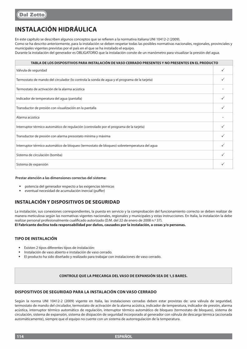
ESPAÑOL
INSTALACIÓN HIDRÁULICAEn este capítulo se describen algunos conceptos que se re�eren a la normativa italiana UNI 10412-2 (2009). Como se ha descrito anteriormente, para la instalación se deben respetar todas las posibles normativas nacionales, regionales, provinciales y municipales vigentes previstas por el país en el que se ha instalado el equipo.Durante la instalación del generador es OBLIGATORIO que la instalación conste de un manómetro para visualizar la presión del agua.
TABLA DE LOS DISPOSITIVOS PARA INSTALACIÓN DE VASO CERRADO PRESENTES Y NO PRESENTES EN EL PRODUCTO
Válvula de seguridad p
Termostato de mando del circulador (lo controla la sonda de agua y el programa de la tarjeta) p
Termostato de activación de la alarma acústica -
Indicador de temperatura del agua (pantalla) p
Transductor de presión con visualización en la pantalla p
Alarma acústica -
Interruptor térmico automático de regulación (controlado por el programa de la tarjeta) p
Transductor de presión con alarma presostato mínima y máxima p
Interruptor térmico automático de bloqueo (termostato de bloqueo) sobretemperatura del agua p
Sistema de circulación (bomba) p
Sistema de expansión p
INSTALACIÓN Y DISPOSITIVOS DE SEGURIDAD
La instalación, sus conexiones correspondientes, la puesta en servicio y la comprobación del funcionamiento correcto se deben realizar de manera meticulosa según las normativas vigentes nacionales, regionales y municipales y estas instrucciones. En Italia, la instalación la debe realizar personal profesionalmente cuali�cado autorizado (D.M. del 22 de enero de 2008 n.º 37).El Fabricante declina toda responsabilidad por daños, causados por la instalación, a cosas y/o personas.
TIPO DE INSTALACIÓN
� Existen 2 tipos diferentes tipos de instalación: � Instalación de vaso abierto e instalación de vaso cerrado. � El producto ha sido diseñado y realizado para trabajar con instalaciones de vaso cerrado.
CONTROLE QUE LA PRECARGA DEL VASO DE EXPANSIÓN SEA DE 1,5 BARES.
DISPOSITIVOS DE SEGURIDAD PARA LA INSTALACIÓN CON VASO CERRADO
Según la norma UNI 10412-2 (2009) vigente en Italia, las instalaciones cerradas deben estar provistas de: una válvula de seguridad, termostato de mando del circulador, termostato de activación de la alarma acústica, indicador de temperatura, indicador de presión, alarma acústica, interruptor térmico automático de regulación, interruptor térmico automático de bloqueo (termostato de bloqueo), sistema de circulación, sistema de expansión, sistema de disipación de seguridad incorporado al generador con válvula de descarga térmica (accionada automáticamente), siempre que el equipo no cuente con un sistema de autorregulación de la temperatura.
Prestar atención a las dimensiones correctas del sistema:
� potencia del generador respecto a las exigencias térmicas � eventual necesidad de acumulación inercial (pu�er)
114
ESPAÑOL
DISTANCIAS DE LOS DISPOSITIVOS DE SEGURIDAD SEGÚN LA NORMATIVA
Los sensores de seguridad de la temperatura deben estar en la máquina o a una distancia de la conexión de ida que no supere los 30 cm. Si los generadores no cuentan con todos los dispositivos, los faltantes se pueden instalar en las tuberías de ida del generador a una distancia de la máquina que no sea superior a 1 m.
CONTROLES CON EL PRIMER ENCENDIDO
Antes de conectar la caldera:a) lave cuidadosamente todas las tuberías de la instalación para eliminar posibles residuos que podrían comprometer el buen funcionamiento de algún componente de la instalación (bombas, válvulas, etc.).b La empresa recomienda instalar en el retorno del generador un �ltro magnético que prolonga la vida útil de la caldera, facilita la remoción de las impurezas y aumenta la e�ciencia global de la instalación.c) veri�que el tiro adecuado de la chimenea, la ausencia de estrangulamientos y controle que no haya descargas de otros equipos en el conducto de salida de humos. Todo esto para evitar aumentos de potencia no previstos. Solo después de este control se puede montar el racor chimenea entre la caldera y el conducto de salida de humos. Se recomienda un control de los racores con conductos de salida de humos ya existentes.
DISPOSITIVO ANTICONDENSACIÓN (OBLIGATORIO)Es obligatorio realizar un adecuado circuito de anticondensación, que garantice una temperatura de retorno del equipo por lo menos de 55°C. La válvula anticondensación, por ejemplo, encuentra aplicación en las calderas de combustible sólido puesto que previene el retorno de agua fría en el intercambiador. Una temperatura de retorno elevada permite mejorar la e�ciencia, reduce la formación de condensación de los humos y alarga la vida útil del generador. El fabricante recomienda el uso del modelo 55°C con conexiones hidráulicas de 1’’.Para los productos con control del circulador PWM la instalación se considera equivalente a la realización de un adecuado circuito anticondensación en caso que:
- el circulador del generador de calor es uno solo en la instalación, o- entre el generador de calor y la instalación está colocado un intercambiador de placas, o- entre el generador de calor y la instalación está colocado un compensador hidráulico o una acumulación inercial (pu�er)
Válvula en venta como accesorio (opción)
115
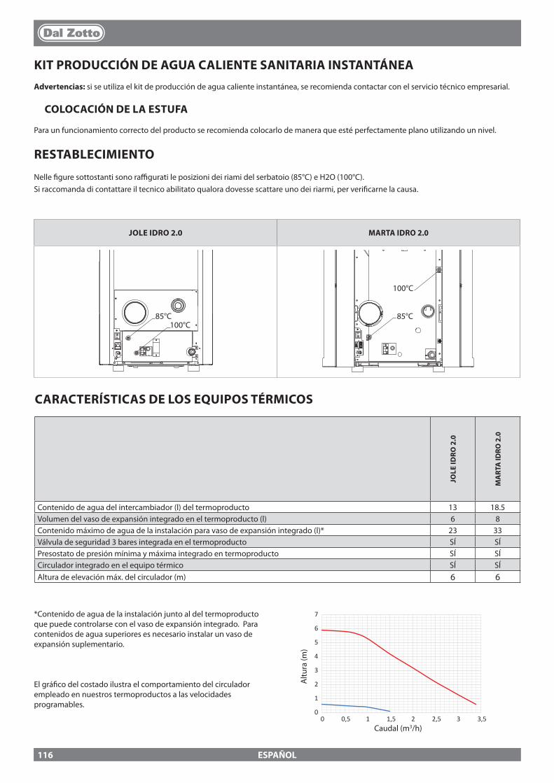
0
1
2
3
4
5
6
7
0 0,5 1 1,5 2 2,5 3 3,5
JOLE IDRO 2.0 MARTA IDRO 2.0
85°C 100°C
85°C 85°C
100°C
100°C
85°C 100°C
85°C 85°C
100°C
100°C
ESPAÑOL
KIT PRODUCCIÓN DE AGUA CALIENTE SANITARIA INSTANTÁNEAAdvertencias: si se utiliza el kit de producción de agua caliente instantánea, se recomienda contactar con el servicio técnico empresarial.
COLOCACIÓN DE LA ESTUFA
Para un funcionamiento correcto del producto se recomienda colocarlo de manera que esté perfectamente plano utilizando un nivel.
RESTABLECIMIENTO
Nelle �gure sottostanti sono ra�gurati le posizioni dei riami del serbatoio (85°C) e H2O (100°C).Si raccomanda di contattare il tecnico abilitato qualora dovesse scattare uno dei riarmi, per veri�carne la causa.
*Contenido de agua de la instalación junto al del termoproducto que puede controlarse con el vaso de expansión integrado. Para contenidos de agua superiores es necesario instalar un vaso de expansión suplementario.
El grá�co del costado ilustra el comportamiento del circulador empleado en nuestros termoproductos a las velocidades programables.
Caudal (m3/h)
Altu
ra (m
)
CARACTERÍSTICAS DE LOS EQUIPOS TÉRMICOS
JOLE
IDRO
2.0
MA
RTA
IDRO
2.0
Contenido de agua del intercambiador (l) del termoproducto 13 18.5Volumen del vaso de expansión integrado en el termoproducto (l) 6 8Contenido máximo de agua de la instalación para vaso de expansión integrado (l)* 23 33Válvula de seguridad 3 bares integrada en el termoproducto SÍ SÍPresostato de presión mínima y máxima integrado en termoproducto SÍ SÍCirculador integrado en el equipo térmico SÍ SÍAltura de elevación máx. del circulador (m) 6 6
116
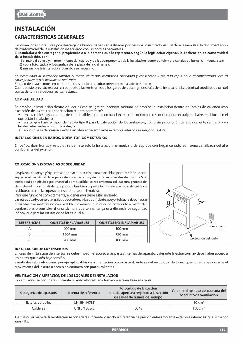
A
CB
ESPAÑOL
Toma de aireREFERENCIAS OBJETOS INFLAMABLES OBJETOS NO INFLAMABLES
A 200 mm 100 mm
B 1500 mm 750 mm
C 200 mm 100 mm protección del suelo
INSTALACIÓN DE LOS INSERTOSEn caso de instalación de insertos, se debe impedir el acceso a las partes internas del aparato, y durante la extracción no debe haber acceso a las partes que estén bajo tensión.Eventuales cableados como por ejemplo cables de alimentación o sondas ambiente se deben colocar de forma que no se dañen durante el movimiento del inserto o entren en contacto con partes calientes.
VENTILACIÓN Y AIREACIÓN DE LOS LOCALES DE INSTALACIÓNLa ventilación se considera su�ciente cuando el local tiene tomas de aire en base a la tabla:
Categorías de aparatos Norma de referenciaPorcentaje de la sección
neta de apertura respecto a la sección de salida de humos del equipo
Valor mínimo neto de apertura del conducto de ventilación
Estufas de pellet UNI EN 14785 - 80 cm²
Calderas UNI EN 303-5 50 % 100 cm²
De cualquier manera, la ventilación se considera su�ciente, cuando la diferencia de presión entre ambiente externo e interno es igual o menor que 4 Pa.
INSTALACIÓNCARACTERÍSTICAS GENERALES
Las conexiones hidráulicas y de descarga de humos deben ser realizadas por personal cuali�cado, el cual debe suministrar la documentación de conformidad de la instalación de acuerdo con las normas nacionales.El instalador debe entregar al propietario o a la persona que lo represente, según la legislación vigente, la declaración de conformidad de la instalación, con:
1) el manual de uso y mantenimiento del equipo y de los componentes de la instalación (como por ejemplo canales de humo, chimenea, etc.);2) copia fotostática o fotográ�ca de la placa de la chimenea;3) manual de la instalación (cuando sea necesario).
Se recomienda al instalador solicitar el recibo de la documentación entregada y conservarlo junto a la copia de la documentación técnica correspondiente a la instalación realizada.En caso de instalaciones en condominios, se debe consultar previamente al administrador.Cuando esté previsto realizar un control de las emisiones de los gases de descarga después de la instalación. La eventual predisposición del punto de toma se deberá realizar estanco.
COMPATIBILIDAD
Se prohíbe la instalación dentro de locales con peligro de incendio. Además, se prohíbe la instalación dentro de locales de vivienda (con excepción de los equipos con funcionamiento hermético):
� en los cuales haya equipos de combustible líquido con funcionamiento continuo o discontinuo que extraigan el aire en el local en el que están instalados, o
� en los que haya equipos de gas de tipo B para la calefacción de los ambientes, con o sin producción de agua caliente sanitaria y en locales adyacentes y comunicantes, o
� en los que la depresión medida en obra entre ambiente externo e interno sea mayor que 4 Pa
INSTALACIONES EN BAÑOS, DORMITORIOS Y ESTUDIOS
En baños, dormitorios y estudios se permite solo la instalación hermética o de equipos con hogar cerrado, con toma canalizada del aire comburente del exterior.
COLOCACIÓN Y DISTANCIAS DE SEGURIDAD
Los planos de apoyo y/o puntos de apoyo deben tener una capacidad portante idónea para soportar el peso total del equipo, de los accesorios y de los revestimientos del mismo Si el suelo está constituido por material combustible, se recomienda utilizar una protección de material incombustible que proteja también la parte frontal de una posible caída de residuos durante las operaciones ordinarias de limpieza.Para que funcione correctamente, el generador debe estar nivelado.Las paredes adyacentes laterales y posteriores y la super�cie de apoyo del suelo deben estar realizadas con material no combustible. Se admite la instalación adyacente a materiales combustibles o sensibles al calor siempre que se mantenga una distancia de seguridad idónea, que para las estufas de pellet es igual a:
117
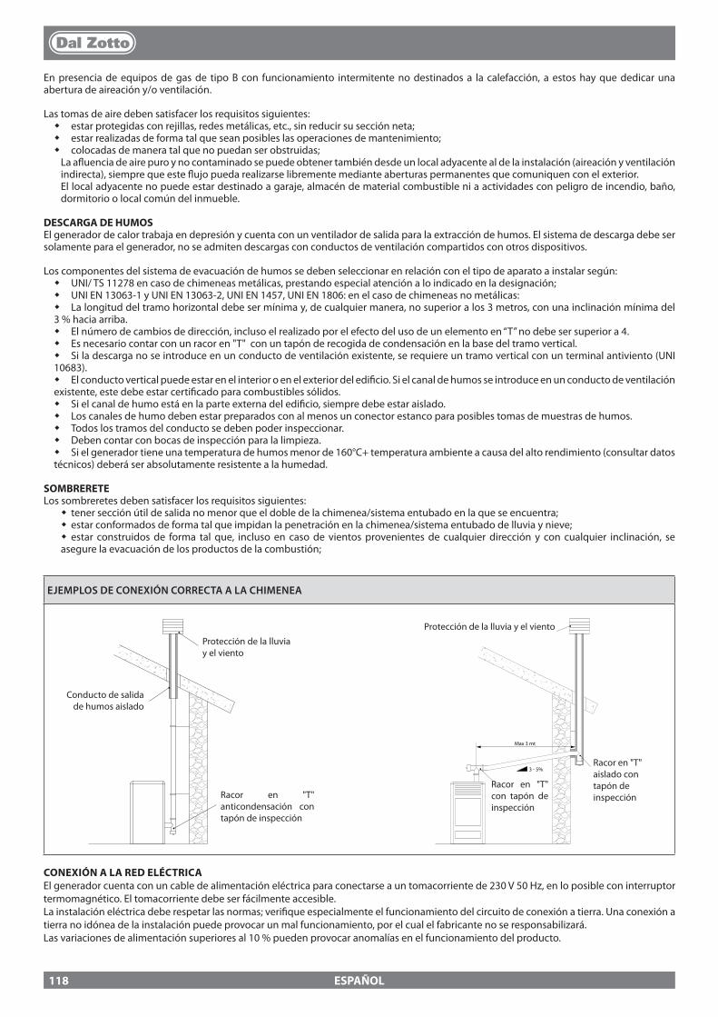
3 - 5%
Max 3 mt
ESPAÑOL
EJEMPLOS DE CONEXIÓN CORRECTA A LA CHIMENEA
En presencia de equipos de gas de tipo B con funcionamiento intermitente no destinados a la calefacción, a estos hay que dedicar una abertura de aireación y/o ventilación.
Las tomas de aire deben satisfacer los requisitos siguientes: � estar protegidas con rejillas, redes metálicas, etc., sin reducir su sección neta; � estar realizadas de forma tal que sean posibles las operaciones de mantenimiento; � colocadas de manera tal que no puedan ser obstruidas;La a�uencia de aire puro y no contaminado se puede obtener también desde un local adyacente al de la instalación (aireación y ventilación indirecta), siempre que este �ujo pueda realizarse libremente mediante aberturas permanentes que comuniquen con el exterior.El local adyacente no puede estar destinado a garaje, almacén de material combustible ni a actividades con peligro de incendio, baño, dormitorio o local común del inmueble.
DESCARGA DE HUMOSEl generador de calor trabaja en depresión y cuenta con un ventilador de salida para la extracción de humos. El sistema de descarga debe ser solamente para el generador, no se admiten descargas con conductos de ventilación compartidos con otros dispositivos.
Los componentes del sistema de evacuación de humos se deben seleccionar en relación con el tipo de aparato a instalar según: � UNI/ TS 11278 en caso de chimeneas metálicas, prestando especial atención a lo indicado en la designación; � UNI EN 13063-1 y UNI EN 13063-2, UNI EN 1457, UNI EN 1806: en el caso de chimeneas no metálicas: � La longitud del tramo horizontal debe ser mínima y, de cualquier manera, no superior a los 3 metros, con una inclinación mínima del
3 % hacia arriba. � El número de cambios de dirección, incluso el realizado por el efecto del uso de un elemento en “T” no debe ser superior a 4. � Es necesario contar con un racor en "T" con un tapón de recogida de condensación en la base del tramo vertical. � Si la descarga no se introduce en un conducto de ventilación existente, se requiere un tramo vertical con un terminal antiviento (UNI
10683). � El conducto vertical puede estar en el interior o en el exterior del edi�cio. Si el canal de humos se introduce en un conducto de ventilación
existente, este debe estar certi�cado para combustibles sólidos. � Si el canal de humo está en la parte externa del edi�cio, siempre debe estar aislado. � Los canales de humo deben estar preparados con al menos un conector estanco para posibles tomas de muestras de humos. � Todos los tramos del conducto se deben poder inspeccionar. � Deben contar con bocas de inspección para la limpieza. � Si el generador tiene una temperatura de humos menor de 160°C+ temperatura ambiente a causa del alto rendimiento (consultar datos
técnicos) deberá ser absolutamente resistente a la humedad.
SOMBRERETELos sombreretes deben satisfacer los requisitos siguientes:
� tener sección útil de salida no menor que el doble de la chimenea/sistema entubado en la que se encuentra; � estar conformados de forma tal que impidan la penetración en la chimenea/sistema entubado de lluvia y nieve; � estar construidos de forma tal que, incluso en caso de vientos provenientes de cualquier dirección y con cualquier inclinación, se
asegure la evacuación de los productos de la combustión;
Protección de la lluvia y el viento
Racor en "T" anticondensación con tapón de inspección
Conducto de salida de humos aislado
Racor en "T" aislado con tapón de inspección
Protección de la lluvia y el viento
Racor en "T" con tapón de inspección
CONEXIÓN A LA RED ELÉCTRICAEl generador cuenta con un cable de alimentación eléctrica para conectarse a un tomacorriente de 230 V 50 Hz, en lo posible con interruptor termomagnético. El tomacorriente debe ser fácilmente accesible.La instalación eléctrica debe respetar las normas; veri�que especialmente el funcionamiento del circuito de conexión a tierra. Una conexión a tierra no idónea de la instalación puede provocar un mal funcionamiento, por el cual el fabricante no se responsabilizará. Las variaciones de alimentación superiores al 10 % pueden provocar anomalías en el funcionamiento del producto.
118
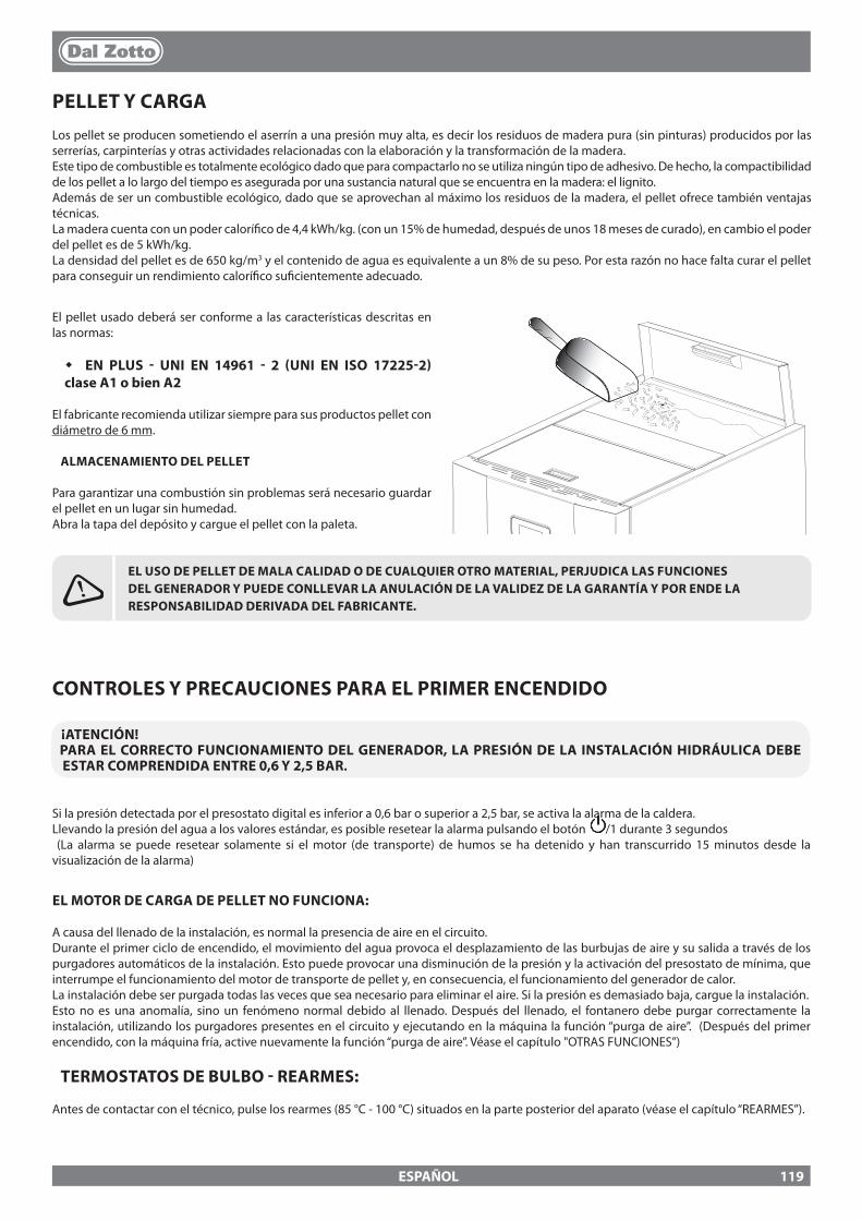
ESPAÑOL
PELLET Y CARGALos pellet se producen sometiendo el aserrín a una presión muy alta, es decir los residuos de madera pura (sin pinturas) producidos por las serrerías, carpinterías y otras actividades relacionadas con la elaboración y la transformación de la madera. Este tipo de combustible es totalmente ecológico dado que para compactarlo no se utiliza ningún tipo de adhesivo. De hecho, la compactibilidad de los pellet a lo largo del tiempo es asegurada por una sustancia natural que se encuentra en la madera: el lignito.Además de ser un combustible ecológico, dado que se aprovechan al máximo los residuos de la madera, el pellet ofrece también ventajas técnicas.La madera cuenta con un poder calorí�co de 4,4 kWh/kg. (con un 15% de humedad, después de unos 18 meses de curado), en cambio el poder del pellet es de 5 kWh/kg.La densidad del pellet es de 650 kg/m3 y el contenido de agua es equivalente a un 8% de su peso. Por esta razón no hace falta curar el pellet para conseguir un rendimiento calorí�co su�cientemente adecuado.
EL USO DE PELLET DE MALA CALIDAD O DE CUALQUIER OTRO MATERIAL, PERJUDICA LAS FUNCIONES DEL GENERADOR Y PUEDE CONLLEVAR LA ANULACIÓN DE LA VALIDEZ DE LA GARANTÍA Y POR ENDE LA RESPONSABILIDAD DERIVADA DEL FABRICANTE.
El pellet usado deberá ser conforme a las características descritas en las normas:
� EN PLUS - UNI EN 14961 - 2 (UNI EN ISO 17225-2) clase A1 o bien A2
El fabricante recomienda utilizar siempre para sus productos pellet con diámetro de 6 mm.
ALMACENAMIENTO DEL PELLET
Para garantizar una combustión sin problemas será necesario guardar el pellet en un lugar sin humedad.Abra la tapa del depósito y cargue el pellet con la paleta.
CONTROLES Y PRECAUCIONES PARA EL PRIMER ENCENDIDO
¡ATENCIÓN!PARA EL CORRECTO FUNCIONAMIENTO DEL GENERADOR, LA PRESIÓN DE LA INSTALACIÓN HIDRÁULICA DEBE ESTAR COMPRENDIDA ENTRE 0,6 Y 2,5 BAR.
Si la presión detectada por el presostato digital es inferior a 0,6 bar o superior a 2,5 bar, se activa la alarma de la caldera.Llevando la presión del agua a los valores estándar, es posible resetear la alarma pulsando el botón /1 durante 3 segundos (La alarma se puede resetear solamente si el motor (de transporte) de humos se ha detenido y han transcurrido 15 minutos desde la visualización de la alarma)
EL MOTOR DE CARGA DE PELLET NO FUNCIONA:
A causa del llenado de la instalación, es normal la presencia de aire en el circuito.Durante el primer ciclo de encendido, el movimiento del agua provoca el desplazamiento de las burbujas de aire y su salida a través de los purgadores automáticos de la instalación. Esto puede provocar una disminución de la presión y la activación del presostato de mínima, que interrumpe el funcionamiento del motor de transporte de pellet y, en consecuencia, el funcionamiento del generador de calor.La instalación debe ser purgada todas las veces que sea necesario para eliminar el aire. Si la presión es demasiado baja, cargue la instalación.Esto no es una anomalía, sino un fenómeno normal debido al llenado. Después del llenado, el fontanero debe purgar correctamente la instalación, utilizando los purgadores presentes en el circuito y ejecutando en la máquina la función “purga de aire”. (Después del primer encendido, con la máquina fría, active nuevamente la función “purga de aire”. Véase el capítulo "OTRAS FUNCIONES”)
TERMOSTATOS DE BULBO - REARMES:
Antes de contactar con el técnico, pulse los rearmes (85 °C - 100 °C) situados en la parte posterior del aparato (véase el capítulo “REARMES”).
119
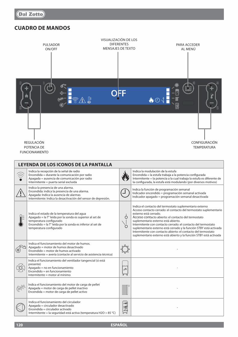
12
3
4
5
6
OFF
ESPAÑOL
CUADRO DE MANDOS
PULSADOR ON/OFF
VISUALIZACIÓN DE LOS DIFERENTES
MENSAJES DE TEXTOPARA ACCEDER
AL MENÚ
CONFIGURACIÓN TEMPERATURA
REGULACIÓN POTENCIA DE
FUNCIONAMIENTO
LEYENDA DE LOS ICONOS DE LA PANTALLAIndica la recepción de la señal de radioEncendida = durante la comunicación por radioApagada = ausencia de comunicación por radioIntermitente = puerta serial excluida
Indica la modulación de la estufaEncendida = la estufa trabaja a la potencia con�guradaIntermitente = la potencia a la cual trabaja la estufa es diferente de la con�gurada, la estufa está modulando (por diversos motivos)
Indica la presencia de una alarma.Encendida: indica la presencia de una alarma.Apagada: Indica la ausencia de alarmasIntermitente: Indica la desactivación del sensor de depresión.
Indica la función de programación semanalIndicador encendido = programación semanal activadaIndicador apagado = programación semanal desactivada
Indica el estado de la temperatura del aguaApagado = la T° leída por la sonda es superior al set de temperatura con�guradoEncendido = la T° leída por la sonda es inferior al set de temperatura con�gurado
Indica el contacto del termostato suplementario externoAcceso contacto cerrado: el contacto del termostato suplementario externo está cerrado.Acceso contacto abierto: el contacto del termostato suplementario externo está abierto.Intermitente con contacto cerrado: el contacto del termostato suplementario externo está cerrado y la función STBY está activadaIntermitente con contacto abierto: el contacto del termostato suplementario externo está abierto y la función STBY está activada
Indica el funcionamiento del motor de humos.Apagado = motor de humos desactivadoEncendido = motor de humos activadoIntermitente = avería (contacte al servicio de asistencia técnica)
-
Indica el funcionamiento del ventilador tangencial (si está presente)Apagado = no en funcionamientoEncendido = en funcionamientoIntermitente = motor al mínimo
-
Indica el funcionamiento del motor de carga de pelletApagada = motor de carga de pellet inactivoEncendida = motor de carga de pellet activo
-
Indica el funcionamiento del circuladorApagada = circulador desactivadoEncendida = circulador activadoIntermitente = la seguridad está activa (temperatura H2O > 85 °C)
-
120
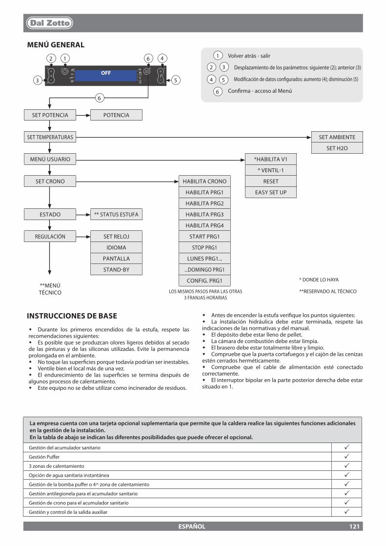
OFF12
3
4
5
6
1
2 3
4 5
6
12
3
46
5
6
ESPAÑOL
MENÚ GENERALVolver atrás - salir
Desplazamiento de los parámetros: siguiente (2); anterior (3) Modi�cación de datos con�gurados: aumento (4); disminución (5)
Con�rma - acceso al Menú
SET POTENCIA POTENCIA
SET TEMPERATURAS SET AMBIENTE
SET H2O
MENÚ USUARIO *HABILITA V1
* VENTIL-1
SET CRONO HABILITA CRONO RESET
HABILITA PRG1 EASY SET UP
HABILITA PRG2
ESTADO ** STATUS ESTUFA HABILITA PRG3
HABILITA PRG4
REGULACIÓN SET RELOJ START PRG1
IDIOMA STOP PRG1
PANTALLA LUNES PRG1...
STAND-BY ...DOMINGO PRG1
**MENÚTÉCNICO
CONFIG. PRG1 * DONDE LO HAYA
**RESERVADO AL TÉCNICOLOS MISMOS PASOS PARA LAS OTRAS 3 FRANJAS HORARIAS
La empresa cuenta con una tarjeta opcional suplementaria que permite que la caldera realice las siguientes funciones adicionales en la gestión de la instalación. En la tabla de abajo se indican las diferentes posibilidades que puede ofrecer el opcional.
Gestión del acumulador sanitario pGestión Pu�er p3 zonas de calentamiento pOpción de agua sanitaria instantánea pGestión de la bomba pu�er o 4^ zona de calentamiento pGestión antilegionela para el acumulador sanitario pGestión de crono para el acumulador sanitario pGestión y control de la salida auxiliar p
INSTRUCCIONES DE BASE
� Durante los primeros encendidos de la estufa, respete las recomendaciones siguientes:� Es posible que se produzcan olores ligeros debidos al secado de las pinturas y de las siliconas utilizadas. Evite la permanencia prolongada en el ambiente.� No toque las super�cies porque todavía podrían ser inestables.� Ventile bien el local más de una vez.� El endurecimiento de las super�cies se termina después de algunos procesos de calentamiento.� Este equipo no se debe utilizar como incinerador de residuos.
� Antes de encender la estufa veri�que los puntos siguientes:� La instalación hidráulica debe estar terminada, respete las indicaciones de las normativas y del manual.� El depósito debe estar lleno de pellet.� La cámara de combustión debe estar limpia.� El brasero debe estar totalmente libre y limpio.� Compruebe que la puerta cortafuegos y el cajón de las cenizas estén cerrados herméticamente.� Compruebe que el cable de alimentación esté conectado correctamente.� El interruptor bipolar en la parte posterior derecha debe estar situado en 1.
121
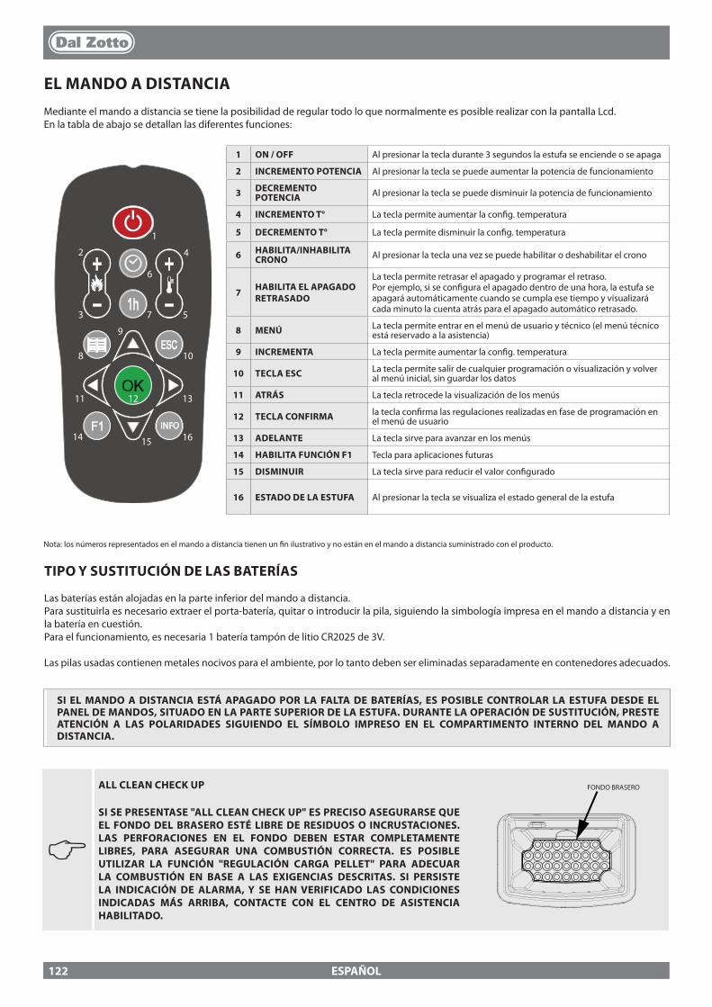
ESPAÑOL
EL MANDO A DISTANCIAMediante el mando a distancia se tiene la posibilidad de regular todo lo que normalmente es posible realizar con la pantalla Lcd.En la tabla de abajo se detallan las diferentes funciones:
INFO
1
2
3
4
5
6
7
8
9
10
11 12 13
14 15 16
1 ON / OFF Al presionar la tecla durante 3 segundos la estufa se enciende o se apaga
2 INCREMENTO POTENCIA Al presionar la tecla se puede aumentar la potencia de funcionamiento
3 DECREMENTO POTENCIA Al presionar la tecla se puede disminuir la potencia de funcionamiento
4 INCREMENTO T° La tecla permite aumentar la con�g. temperatura
5 DECREMENTO T° La tecla permite disminuir la con�g. temperatura
6 HABILITA/INHABILITA CRONO Al presionar la tecla una vez se puede habilitar o deshabilitar el crono
7 HABILITA EL APAGADO RETRASADO
La tecla permite retrasar el apagado y programar el retraso. Por ejemplo, si se con�gura el apagado dentro de una hora, la estufa se apagará automáticamente cuando se cumpla ese tiempo y visualizará cada minuto la cuenta atrás para el apagado automático retrasado.
8 MENÚ La tecla permite entrar en el menú de usuario y técnico (el menú técnico está reservado a la asistencia)
9 INCREMENTA La tecla permite aumentar la con�g. temperatura
10 TECLA ESC La tecla permite salir de cualquier programación o visualización y volver al menú inicial, sin guardar los datos
11 ATRÁS La tecla retrocede la visualización de los menús
12 TECLA CONFIRMA la tecla con�rma las regulaciones realizadas en fase de programación en el menú de usuario
13 ADELANTE La tecla sirve para avanzar en los menús
14 HABILITA FUNCIÓN F1 Tecla para aplicaciones futuras
15 DISMINUIR La tecla sirve para reducir el valor con�gurado
16 ESTADO DE LA ESTUFA Al presionar la tecla se visualiza el estado general de la estufa
TIPO Y SUSTITUCIÓN DE LAS BATERÍAS
Las baterías están alojadas en la parte inferior del mando a distancia. Para sustituirla es necesario extraer el porta-batería, quitar o introducir la pila, siguiendo la simbología impresa en el mando a distancia y en la batería en cuestión.Para el funcionamiento, es necesaria 1 batería tampón de litio CR2025 de 3V.
Las pilas usadas contienen metales nocivos para el ambiente, por lo tanto deben ser eliminadas separadamente en contenedores adecuados.
Nota: los números representados en el mando a distancia tienen un �n ilustrativo y no están en el mando a distancia suministrado con el producto.
SI EL MANDO A DISTANCIA ESTÁ APAGADO POR LA FALTA DE BATERÍAS, ES POSIBLE CONTROLAR LA ESTUFA DESDE EL PANEL DE MANDOS, SITUADO EN LA PARTE SUPERIOR DE LA ESTUFA. DURANTE LA OPERACIÓN DE SUSTITUCIÓN, PRESTE ATENCIÓN A LAS POLARIDADES SIGUIENDO EL SÍMBOLO IMPRESO EN EL COMPARTIMENTO INTERNO DEL MANDO A DISTANCIA.
J
ALL CLEAN CHECK UP
SI SE PRESENTASE "ALL CLEAN CHECK UP" ES PRECISO ASEGURARSE QUE EL FONDO DEL BRASERO ESTÉ LIBRE DE RESIDUOS O INCRUSTACIONES. LAS PERFORACIONES EN EL FONDO DEBEN ESTAR COMPLETAMENTE LIBRES, PARA ASEGURAR UNA COMBUSTIÓN CORRECTA. ES POSIBLE UTILIZAR LA FUNCIÓN "REGULACIÓN CARGA PELLET" PARA ADECUAR LA COMBUSTIÓN EN BASE A LAS EXIGENCIAS DESCRITAS. SI PERSISTE LA INDICACIÓN DE ALARMA, Y SE HAN VERIFICADO LAS CONDICIONES INDICADAS MÁS ARRIBA, CONTACTE CON EL CENTRO DE ASISTENCIA HABILITADO.
FONDO BRASERO
122
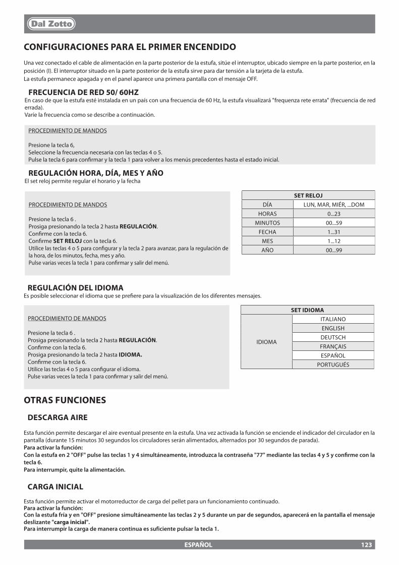
ESPAÑOL
REGULACIÓN HORA, DÍA, MES Y AÑOEl set reloj permite regular el horario y la fecha
PROCEDIMIENTO DE MANDOS
Presione la tecla 6 .Prosiga presionando la tecla 2 hasta REGULACIÓN.Con�rme con la tecla 6.Prosiga presionando la tecla 2 hasta IDIOMA.Con�rme con la tecla 6.Utilice las teclas 4 o 5 para con�gurar el idioma.Pulse varias veces la tecla 1 para con�rmar y salir del menú.
SET IDIOMA
IDIOMA
ITALIANO
ENGLISH
DEUTSCH
FRANÇAIS
ESPAÑOL
PORTUGUÉS
CONFIGURACIONES PARA EL PRIMER ENCENDIDO
Una vez conectado el cable de alimentación en la parte posterior de la estufa, sitúe el interruptor, ubicado siempre en la parte posterior, en la posición (I). El interruptor situado en la parte posterior de la estufa sirve para dar tensión a la tarjeta de la estufa.La estufa permanece apagada y en el panel aparece una primera pantalla con el mensaje OFF.
OTRAS FUNCIONES
DESCARGA AIRE
Esta función permite descargar el aire eventual presente en la estufa. Una vez activada la función se enciende el indicador del circulador en la pantalla (durante 15 minutos 30 segundos los circuladores serán alimentados, alternados por 30 segundos de parada).Para activar la función:Con la estufa en 2 "OFF" pulse las teclas 1 y 4 simultáneamente, introduzca la contraseña "77" mediante las teclas 4 y 5 y con�rme con la tecla 6. Para interrumpir, quite la alimentación.
CARGA INICIAL
Esta función permite activar el motorreductor de carga del pellet para un funcionamiento continuado. Para activar la función:Con la estufa fría y en "OFF" presione simultáneamente las teclas 2 y 5 durante un par de segundos, aparecerá en la pantalla el mensaje deslizante "carga inicial".Para interrumpir la carga de manera continua es suficiente pulsar la tecla 1.
PROCEDIMIENTO DE MANDOS
Presione la tecla 6 .Prosiga presionando la tecla 2 hasta REGULACIÓN.Con�rme con la tecla 6.Con�rme SET RELOJ con la tecla 6.Utilice las teclas 4 o 5 para con�gurar y la tecla 2 para avanzar, para la regulación de la hora, de los minutos, fecha, mes y año.Pulse varias veces la tecla 1 para con�rmar y salir del menú.
SET RELOJDÍA LUN, MAR, MIÉR, ...DOM
HORAS 0...23
MINUTOS 00...59
FECHA 1...31
MES 1...12
AÑO 00...99
REGULACIÓN DEL IDIOMAEs posible seleccionar el idioma que se pre�ere para la visualización de los diferentes mensajes.
FRECUENCIA DE RED 50/ 60HZEn caso de que la estufa esté instalada en un país con una frecuencia de 60 Hz, la estufa visualizará "frequenza rete errata" (frecuencia de red errada).Varíe la frecuencia como se describe a continuación.
PROCEDIMIENTO DE MANDOS
Presione la tecla 6, Seleccione la frecuencia necesaria con las teclas 4 o 5.Pulse la tecla 6 para con�rmar y la tecla 1 para volver a los menús precedentes hasta el estado inicial.
123
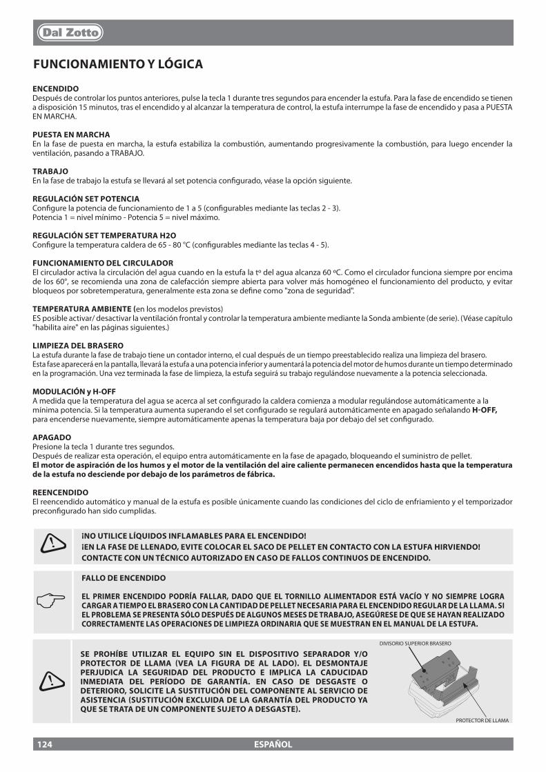
ESPAÑOL
FUNCIONAMIENTO Y LÓGICA
ENCENDIDODespués de controlar los puntos anteriores, pulse la tecla 1 durante tres segundos para encender la estufa. Para la fase de encendido se tienen a disposición 15 minutos, tras el encendido y al alcanzar la temperatura de control, la estufa interrumpe la fase de encendido y pasa a PUESTA EN MARCHA.
PUESTA EN MARCHAEn la fase de puesta en marcha, la estufa estabiliza la combustión, aumentando progresivamente la combustión, para luego encender la ventilación, pasando a TRABAJO.
TRABAJOEn la fase de trabajo la estufa se llevará al set potencia con�gurado, véase la opción siguiente.
REGULACIÓN SET POTENCIACon�gure la potencia de funcionamiento de 1 a 5 (con�gurables mediante las teclas 2 - 3).Potencia 1 = nivel mínimo - Potencia 5 = nivel máximo.
REGULACIÓN SET TEMPERATURA H2OCon�gure la temperatura caldera de 65 - 80 °C (con�gurables mediante las teclas 4 - 5).
FUNCIONAMIENTO DEL CIRCULADOREl circulador activa la circulación del agua cuando en la estufa la tº del agua alcanza 60 ºC. Como el circulador funciona siempre por encima de los 60°, se recomienda una zona de calefacción siempre abierta para volver más homogéneo el funcionamiento del producto, y evitar bloqueos por sobretemperatura, generalmente esta zona se de�ne como "zona de seguridad".
TEMPERATURA AMBIENTE (en los modelos previstos)ES posible activar/ desactivar la ventilación frontal y controlar la temperatura ambiente mediante la Sonda ambiente (de serie). (Véase capítulo "habilita aire" en las páginas siguientes.)
LIMPIEZA DEL BRASEROLa estufa durante la fase de trabajo tiene un contador interno, el cual después de un tiempo preestablecido realiza una limpieza del brasero.Esta fase aparecerá en la pantalla, llevará la estufa a una potencia inferior y aumentará la potencia del motor de humos durante un tiempo determinado en la programación. Una vez terminada la fase de limpieza, la estufa seguirá su trabajo regulándose nuevamente a la potencia seleccionada.
MODULACIÓN y H-OFFA medida que la temperatura del agua se acerca al set con�gurado la caldera comienza a modular regulándose automáticamente a la mínima potencia. Si la temperatura aumenta superando el set con�gurado se regulará automáticamente en apagado señalando H-OFF, para encenderse nuevamente, siempre automáticamente apenas la temperatura baja por debajo del set con�gurado.
APAGADOPresione la tecla 1 durante tres segundos.Después de realizar esta operación, el equipo entra automáticamente en la fase de apagado, bloqueando el suministro de pellet.El motor de aspiración de los humos y el motor de la ventilación del aire caliente permanecen encendidos hasta que la temperatura de la estufa no desciende por debajo de los parámetros de fábrica.
REENCENDIDOEl reencendido automático y manual de la estufa es posible únicamente cuando las condiciones del ciclo de enfriamiento y el temporizador precon�gurado han sido cumplidas.
J FALLO DE ENCENDIDO
EL PRIMER ENCENDIDO PODRÍA FALLAR, DADO QUE EL TORNILLO ALIMENTADOR ESTÁ VACÍO Y NO SIEMPRE LOGRA CARGAR A TIEMPO EL BRASERO CON LA CANTIDAD DE PELLET NECESARIA PARA EL ENCENDIDO REGULAR DE LA LLAMA. SI EL PROBLEMA SE PRESENTA SÓLO DESPUÉS DE ALGUNOS MESES DE TRABAJO, ASEGÚRESE DE QUE SE HAYAN REALIZADO CORRECTAMENTE LAS OPERACIONES DE LIMPIEZA ORDINARIA QUE SE MUESTRAN EN EL MANUAL DE LA ESTUFA.
¡NO UTILICE LÍQUIDOS INFLAMABLES PARA EL ENCENDIDO!¡EN LA FASE DE LLENADO, EVITE COLOCAR EL SACO DE PELLET EN CONTACTO CON LA ESTUFA HIRVIENDO!CONTACTE CON UN TÉCNICO AUTORIZADO EN CASO DE FALLOS CONTINUOS DE ENCENDIDO.
SE PROHÍBE UTILIZAR EL EQUIPO SIN EL DISPOSITIVO SEPARADOR Y/O PROTECTOR DE LLAMA (VEA LA FIGURA DE AL LADO). EL DESMONTAJE PERJUDICA LA SEGURIDAD DEL PRODUCTO E IMPLICA LA CADUCIDAD INMEDIATA DEL PERÍODO DE GARANTÍA. EN CASO DE DESGASTE O DETERIORO, SOLICITE LA SUSTITUCIÓN DEL COMPONENTE AL SERVICIO DE ASISTENCIA (SUSTITUCIÓN EXCLUIDA DE LA GARANTÍA DEL PRODUCTO YA QUE SE TRATA DE UN COMPONENTE SUJETO A DESGASTE).
DIVISORIO SUPERIOR BRASERO
PROTECTOR DE LLAMA
124
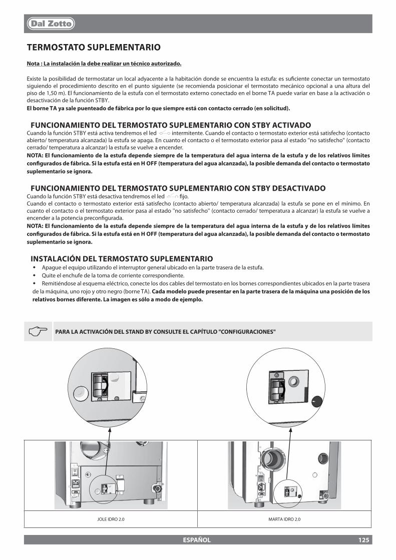
JOLE IDRO 2.0 MARTA IDRO 2.0
ESPAÑOL
TERMOSTATO SUPLEMENTARIO
Nota : La instalación la debe realizar un técnico autorizado.
Existe la posibilidad de termostatar un local adyacente a la habitación donde se encuentra la estufa: es su�ciente conectar un termostato siguiendo el procedimiento descrito en el punto siguiente (se recomienda posicionar el termostato mecánico opcional a una altura del piso de 1,50 m). El funcionamiento de la estufa con el termostato externo conectado en el borne TA puede variar en base a la activación o desactivación de la función STBY.El borne TA ya sale puenteado de fábrica por lo que siempre está con contacto cerrado (en solicitud).
FUNCIONAMIENTO DEL TERMOSTATO SUPLEMENTARIO CON STBY ACTIVADOCuando la función STBY está activa tendremos el led intermitente. Cuando el contacto o termostato exterior está satisfecho (contacto abierto/ temperatura alcanzada) la estufa se apaga. En cuanto el contacto o el termostato exterior pasa al estado ''no satisfecho'' (contacto cerrado/ temperatura a alcanzar) la estufa se vuelve a encender.NOTA: El funcionamiento de la estufa depende siempre de la temperatura del agua interna de la estufa y de los relativos límites con�gurados de fábrica. Si la estufa está en H OFF (temperatura del agua alcanzada), la posible demanda del contacto o termostato suplementario se ignora.
FUNCIONAMIENTO DEL TERMOSTATO SUPLEMENTARIO CON STBY DESACTIVADOCuando la función STBY está desactiva tendremos el led �jo.Cuando el contacto o termostato exterior está satisfecho (contacto abierto/ temperatura alcanzada) la estufa se pone en el mínimo. En cuanto el contacto o el termostato exterior pasa al estado ''no satisfecho'' (contacto cerrado/ temperatura a alcanzar) la estufa se vuelve a encender a la potencia precon�gurada. NOTA: El funcionamiento de la estufa depende siempre de la temperatura del agua interna de la estufa y de los relativos límites con�gurados de fábrica. Si la estufa está en H OFF (temperatura del agua alcanzada), la posible demanda del contacto o termostato suplementario se ignora.
INSTALACIÓN DEL TERMOSTATO SUPLEMENTARIO� Apague el equipo utilizando el interruptor general ubicado en la parte trasera de la estufa.� Quite el enchufe de la toma de corriente correspondiente.� Remitiéndose al esquema eléctrico, conecte los dos cables del termostato en los bornes correspondientes ubicados en la parte trasera de la máquina, uno rojo y otro negro (borne TA). Cada modelo puede presentar en la parte trasera de la máquina una posición de los relativos bornes diferente. La imagen es sólo a modo de ejemplo.
J
PARA LA ACTIVACIÓN DEL STAND BY CONSULTE EL CAPÍTULO "CONFIGURACIONES"
125
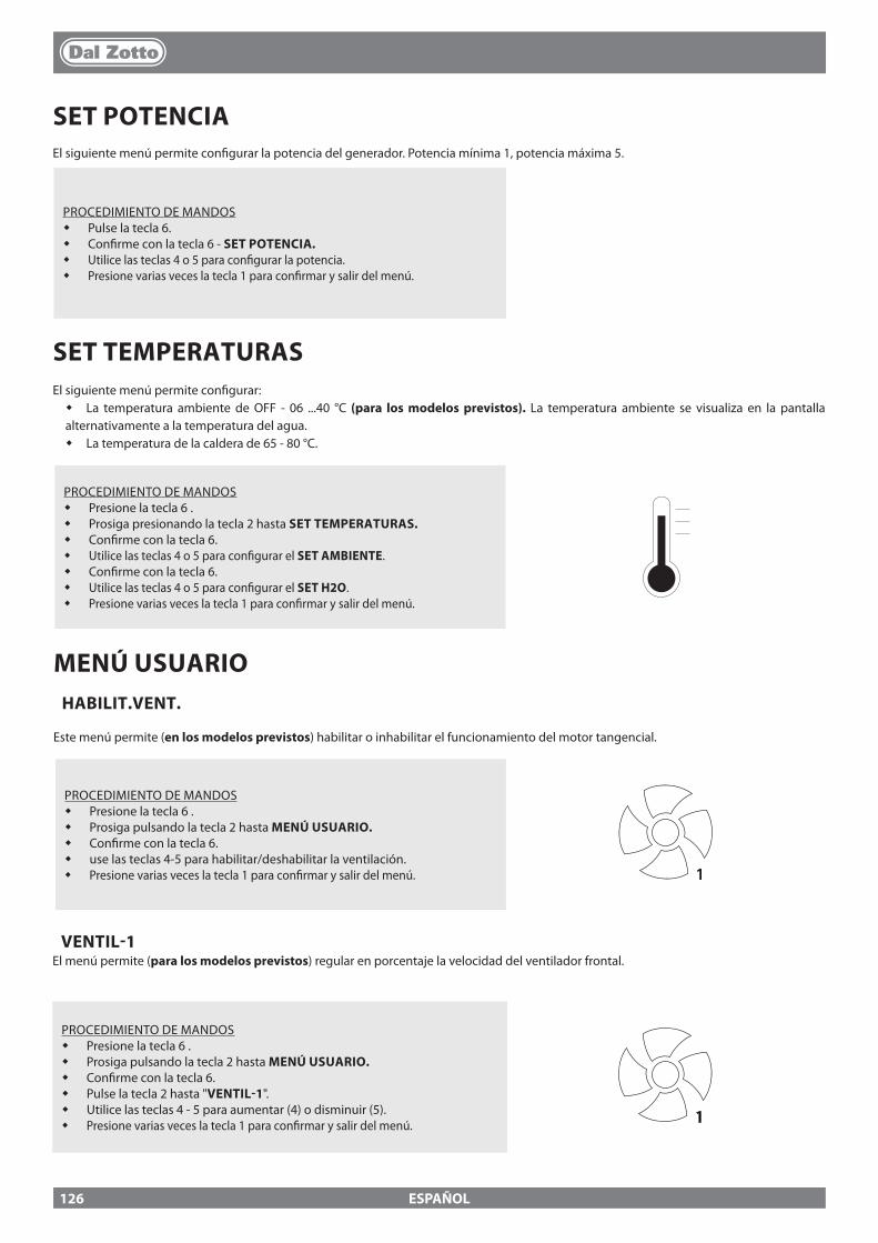
ESPAÑOL
SET POTENCIAEl siguiente menú permite con�gurar la potencia del generador. Potencia mínima 1, potencia máxima 5.
PROCEDIMIENTO DE MANDOS� Pulse la tecla 6.� Con�rme con la tecla 6 - SET POTENCIA.� Utilice las teclas 4 o 5 para con�gurar la potencia.� Presione varias veces la tecla 1 para con�rmar y salir del menú.
SET TEMPERATURASEl siguiente menú permite con�gurar:� La temperatura ambiente de OFF - 06 ...40 °C (para los modelos previstos). La temperatura ambiente se visualiza en la pantalla alternativamente a la temperatura del agua.� La temperatura de la caldera de 65 - 80 °C.
PROCEDIMIENTO DE MANDOS� Presione la tecla 6 .� Prosiga presionando la tecla 2 hasta SET TEMPERATURAS.� Con�rme con la tecla 6.� Utilice las teclas 4 o 5 para con�gurar el SET AMBIENTE.� Con�rme con la tecla 6.� Utilice las teclas 4 o 5 para con�gurar el SET H2O.� Presione varias veces la tecla 1 para con�rmar y salir del menú.
MENÚ USUARIOHABILIT.VENT.
Este menú permite (en los modelos previstos) habilitar o inhabilitar el funcionamiento del motor tangencial.
PROCEDIMIENTO DE MANDOS� Presione la tecla 6 .� Prosiga pulsando la tecla 2 hasta MENÚ USUARIO.� Con�rme con la tecla 6.� use las teclas 4-5 para habilitar/deshabilitar la ventilación. � Presione varias veces la tecla 1 para con�rmar y salir del menú. 1
VENTIL-1El menú permite (para los modelos previstos) regular en porcentaje la velocidad del ventilador frontal.
PROCEDIMIENTO DE MANDOS� Presione la tecla 6 .� Prosiga pulsando la tecla 2 hasta MENÚ USUARIO.� Con�rme con la tecla 6.� Pulse la tecla 2 hasta "VENTIL-1".� Utilice las teclas 4 - 5 para aumentar (4) o disminuir (5).� Presione varias veces la tecla 1 para con�rmar y salir del menú. 1
126
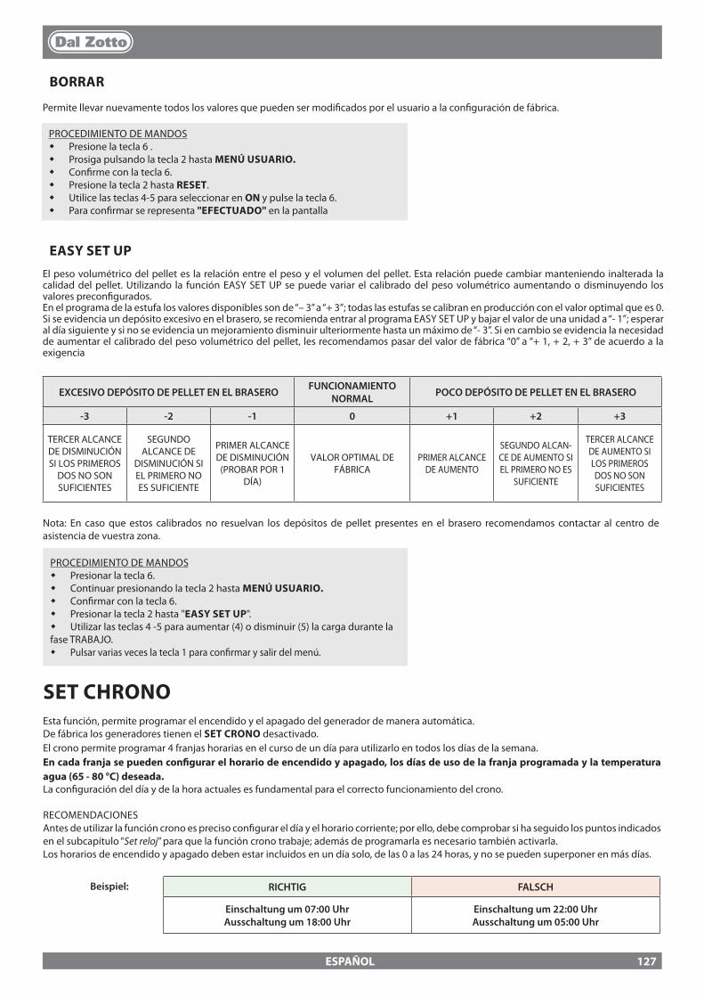
ESPAÑOL
PROCEDIMIENTO DE MANDOS� Presione la tecla 6 .� Prosiga pulsando la tecla 2 hasta MENÚ USUARIO.� Con�rme con la tecla 6.� Presione la tecla 2 hasta RESET.� Utilice las teclas 4-5 para seleccionar en ON y pulse la tecla 6.� Para con�rmar se representa ''EFECTUADO'' en la pantalla
EASY SET UPEl peso volumétrico del pellet es la relación entre el peso y el volumen del pellet. Esta relación puede cambiar manteniendo inalterada la calidad del pellet. Utilizando la función EASY SET UP se puede variar el calibrado del peso volumétrico aumentando o disminuyendo los valores precon�gurados.En el programa de la estufa los valores disponibles son de “– 3” a “+ 3”; todas las estufas se calibran en producción con el valor optimal que es 0.Si se evidencia un depósito excesivo en el brasero, se recomienda entrar al programa EASY SET UP y bajar el valor de una unidad a “- 1”; esperar al día siguiente y si no se evidencia un mejoramiento disminuir ulteriormente hasta un máximo de “- 3”. Si en cambio se evidencia la necesidad de aumentar el calibrado del peso volumétrico del pellet, les recomendamos pasar del valor de fábrica “0” a “+ 1, + 2, + 3” de acuerdo a la exigencia
BORRAR
Permite llevar nuevamente todos los valores que pueden ser modi�cados por el usuario a la con�guración de fábrica.
EXCESIVO DEPÓSITO DE PELLET EN EL BRASERO FUNCIONAMIENTO NORMAL POCO DEPÓSITO DE PELLET EN EL BRASERO
-3 -2 -1 0 +1 +2 +3
TERCER ALCANCE DE DISMINUCIÓN SI LOS PRIMEROS
DOS NO SON SUFICIENTES
SEGUNDO ALCANCE DE
DISMINUCIÓN SI EL PRIMERO NO ES SUFICIENTE
PRIMER ALCANCE DE DISMINUCIÓN
(PROBAR POR 1 DÍA)
VALOR OPTIMAL DE FÁBRICA
PRIMER ALCANCE DE AUMENTO
SEGUNDO ALCAN-CE DE AUMENTO SI EL PRIMERO NO ES
SUFICIENTE
TERCER ALCANCE DE AUMENTO SI LOS PRIMEROS DOS NO SON SUFICIENTES
SET CHRONOEsta función, permite programar el encendido y el apagado del generador de manera automática.De fábrica los generadores tienen el SET CRONO desactivado.El crono permite programar 4 franjas horarias en el curso de un día para utilizarlo en todos los días de la semana. En cada franja se pueden con�gurar el horario de encendido y apagado, los días de uso de la franja programada y la temperatura agua (65 - 80 °C) deseada. La con�guración del día y de la hora actuales es fundamental para el correcto funcionamiento del crono.
RECOMENDACIONESAntes de utilizar la función crono es preciso con�gurar el día y el horario corriente; por ello, debe comprobar si ha seguido los puntos indicados en el subcapítulo “Set reloj” para que la función crono trabaje; además de programarla es necesario también activarla. Los horarios de encendido y apagado deben estar incluidos en un día solo, de las 0 a las 24 horas, y no se pueden superponer en más días.
RICHTIG FALSCH
Einschaltung um 07:00 UhrAusschaltung um 18:00 Uhr
Einschaltung um 22:00 UhrAusschaltung um 05:00 Uhr
Beispiel:
Nota: En caso que estos calibrados no resuelvan los depósitos de pellet presentes en el brasero recomendamos contactar al centro de asistencia de vuestra zona.
PROCEDIMIENTO DE MANDOS� Presionar la tecla 6.� Continuar presionando la tecla 2 hasta MENÚ USUARIO.� Con�rmar con la tecla 6.� Presionar la tecla 2 hasta "EASY SET UP".� Utilizar las teclas 4 -5 para aumentar (4) o disminuir (5) la carga durante la fase TRABAJO.� Pulsar varias veces la tecla 1 para con�rmar y salir del menú.
127
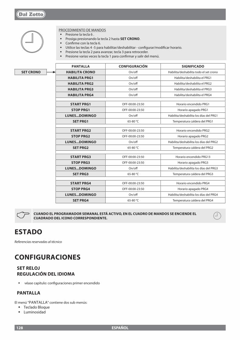
ESPAÑOL
JCUANDO EL PROGRAMADOR SEMANAL ESTÁ ACTIVO, EN EL CUADRO DE MANDOS SE ENCIENDE EL CUADRADO DEL ICONO CORRESPONDIENTE.
PANTALLA CONFIGURACIÓN SIGNIFICADO
SET CRONO HABILITA CRONO On/o� Habilita/deshabilita todo el set crono
HABILITA PRG1 On/o� Habilita/deshabilita el PRG1
HABILITA PRG2 On/o� Habilita/deshabilita el PRG2
HABILITA PRG3 On/o� Habilita/deshabilita el PRG3
HABILITA PRG4 On/o� Habilita/deshabilita el PRG4
START PRG1 OFF-00:00-23:50 Horario encendido PRG1
STOP PRG1 OFF-00:00-23:50 Horario apagado PRG1
LUNES...DOMINGO On/o� Habilita/deshabilita los días del PRG1
SET PRG1 65-80 °C Temperatura caldera del PRG1
START PRG2 OFF-00:00-23:50 Horario encendido PRG2
STOP PRG2 OFF-00:00-23:50 Horario apagado PRG2
LUNES...DOMINGO On/o� Habilita/deshabilita los días del PRG2
SET PRG2 65-80 °C Temperatura caldera del PRG2
START PRG3 OFF-00:00-23:50 Horario encendido PRG13
STOP PRG3 OFF-00:00-23:50 Horario apagado PRG3
LUNES...DOMINGO On/o� Habilita/deshabilita los días del PRG3
SET PRG3 65-80 °C Temperatura caldera del PRG3
START PRG4 OFF-00:00-23:50 Horario encendido PRG4
STOP PRG4 OFF-00:00-23:50 Horario apagado PRG4
LUNES...DOMINGO On/o� Habilita/deshabilita los días del PRG4
SET PRG4 65-80 °C Temperatura caldera del PRG4
PROCEDIMIENTO DE MANDOS� Presione la tecla 6 .� Prosiga presionando la tecla 2 hasta SET CRONO.� Con�rme con la tecla 6.� Utilice las teclas 4 -5 para habilitar/deshabilitar - con�gurar/modi�car horario.� Presione la tecla 2 para avanzar, tecla 3 para retroceder.� Presione varias veces la tecla 1 para con�rmar y salir del menú.
ESTADOReferencias reservadas al técnico
CONFIGURACIONESSET RELOJ REGULACIÓN DEL IDIOMA
� véase capítulo: con�guraciones primer encendido
PANTALLA
El menú "PANTALLA" contiene dos sub menús:� Teclado Bloque� Luminosidad
128
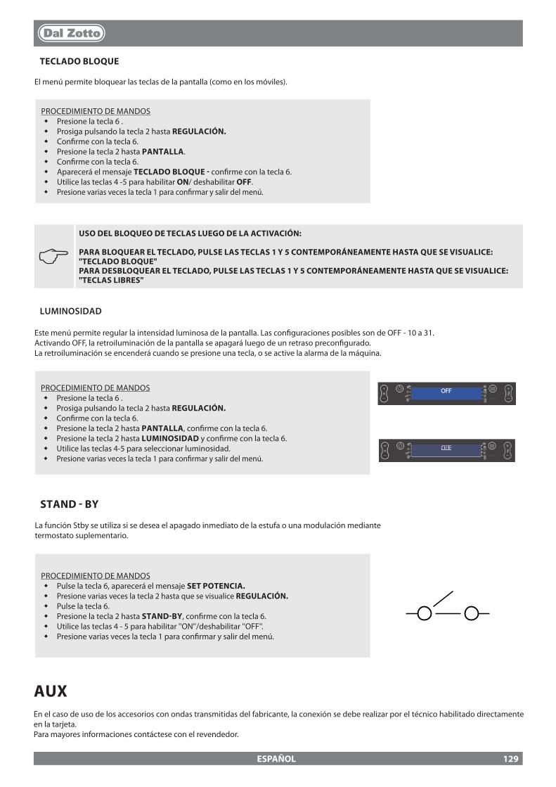
ESPAÑOL
J USO DEL BLOQUEO DE TECLAS LUEGO DE LA ACTIVACIÓN:
PARA BLOQUEAR EL TECLADO, PULSE LAS TECLAS 1 Y 5 CONTEMPORÁNEAMENTE HASTA QUE SE VISUALICE: "TECLADO BLOQUE" PARA DESBLOQUEAR EL TECLADO, PULSE LAS TECLAS 1 Y 5 CONTEMPORÁNEAMENTE HASTA QUE SE VISUALICE: "TECLAS LIBRES"
LUMINOSIDAD
Este menú permite regular la intensidad luminosa de la pantalla. Las con�guraciones posibles son de OFF - 10 a 31.Activando OFF, la retroiluminación de la pantalla se apagará luego de un retraso precon�gurado. La retroiluminación se encenderá cuando se presione una tecla, o se active la alarma de la máquina.
PROCEDIMIENTO DE MANDOS� Presione la tecla 6 .� Prosiga pulsando la tecla 2 hasta REGULACIÓN.� Con�rme con la tecla 6.� Presione la tecla 2 hasta PANTALLA, con�rme con la tecla 6.� Presione la tecla 2 hasta LUMINOSIDAD y con�rme con la tecla 6.� Utilice las teclas 4-5 para seleccionar luminosidad.� Presione varias veces la tecla 1 para con�rmar y salir del menú.
OFF
OFF
TECLADO BLOQUE
El menú permite bloquear las teclas de la pantalla (como en los móviles).
PROCEDIMIENTO DE MANDOS� Presione la tecla 6 .� Prosiga pulsando la tecla 2 hasta REGULACIÓN.� Con�rme con la tecla 6.� Presione la tecla 2 hasta PANTALLA.� Con�rme con la tecla 6.� Aparecerá el mensaje TECLADO BLOQUE - con�rme con la tecla 6.� Utilice las teclas 4 -5 para habilitar ON/ deshabilitar OFF.� Presione varias veces la tecla 1 para con�rmar y salir del menú.
STAND - BY
La función Stby se utiliza si se desea el apagado inmediato de la estufa o una modulación mediante termostato suplementario.
PROCEDIMIENTO DE MANDOS� Pulse la tecla 6, aparecerá el mensaje SET POTENCIA.� Presione varias veces la tecla 2 hasta que se visualice REGULACIÓN.� Pulse la tecla 6.� Presione la tecla 2 hasta STAND-BY, con�rme con la tecla 6.� Utilice las teclas 4 - 5 para habilitar ''ON''/deshabilitar ''OFF''.� Presione varias veces la tecla 1 para con�rmar y salir del menú.
AUXEn el caso de uso de los accesorios con ondas transmitidas del fabricante, la conexión se debe realizar por el técnico habilitado directamente en la tarjeta.Para mayores informaciones contáctese con el revendedor.
129
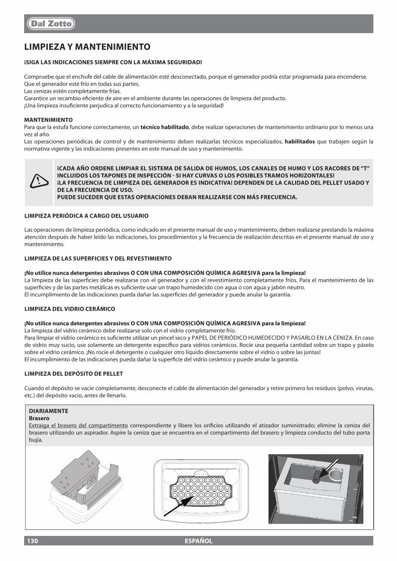
ESPAÑOL
LIMPIEZA Y MANTENIMIENTO¡SIGA LAS INDICACIONES SIEMPRE CON LA MÁXIMA SEGURIDAD!
Compruebe que el enchufe del cable de alimentación esté desconectado, porque el generador podría estar programada para encenderse. Que el generador esté frío en todas sus partes.Las cenizas estén completamente frías.Garantice un recambio e�ciente de aire en el ambiente durante las operaciones de limpieza del producto.¡Una limpieza insu�ciente perjudica al correcto funcionamiento y a la seguridad!
MANTENIMIENTOPara que la estufa funcione correctamente, un técnico habilitado, debe realizar operaciones de mantenimiento ordinario por lo menos una vez al año.Las operaciones periódicas de control y de mantenimiento deben realizarlas técnicos especializados, habilitados que trabajen según la normativa vigente y las indicaciones presentes en este manual de uso y mantenimiento.
DIARIAMENTE Brasero Extraiga el brasero del compartimento correspondiente y libere los ori�cios utilizando el atizador suministrado; elimine la ceniza del brasero utilizando un aspirador. Aspire la ceniza que se encuentra en el compartimento del brasero y limpieza conducto del tubo porta bujía.
¡CADA AÑO ORDENE LIMPIAR EL SISTEMA DE SALIDA DE HUMOS, LOS CANALES DE HUMO Y LOS RACORES DE “T” INCLUIDOS LOS TAPONES DE INSPECCIÓN - SI HAY CURVAS O LOS POSIBLES TRAMOS HORIZONTALES!¡LA FRECUENCIA DE LIMPIEZA DEL GENERADOR ES INDICATIVA! DEPENDEN DE LA CALIDAD DEL PELLET USADO Y DE LA FRECUENCIA DE USO. PUEDE SUCEDER QUE ESTAS OPERACIONES DEBAN REALIZARSE CON MÁS FRECUENCIA.
LIMPIEZA PERIÓDICA A CARGO DEL USUARIO
Las operaciones de limpieza periódica, como indicado en el presente manual de uso y mantenimiento, deben realizarse prestando la máxima atención después de haber leído las indicaciones, los procedimientos y la frecuencia de realización descritas en el presente manual de uso y mantenimiento.
LIMPIEZA DE LAS SUPERFICIES Y DEL REVESTIMIENTO
¡No utilice nunca detergentes abrasivos O CON UNA COMPOSICIÓN QUÍMICA AGRESIVA para la limpieza!La limpieza de las super�cies debe realizarse con el generador y con el revestimiento completamente fríos. Para el mantenimiento de las super�cies y de las partes metálicas es su�ciente usar un trapo humedecido con agua o con agua y jabón neutro.El incumplimiento de las indicaciones pueda dañar las super�cies del generador y puede anular la garantía.
LIMPIEZA DEL VIDRIO CERÁMICO
¡No utilice nunca detergentes abrasivos O CON UNA COMPOSICIÓN QUÍMICA AGRESIVA para la limpieza!La limpieza del vidrio cerámico debe realizarse solo con el vidrio completamente frío. Para limpiar el vidrio cerámico es su�ciente utilizar un pincel seco y PAPEL DE PERIÓDICO HUMEDECIDO Y PASARLO EN LA CENIZA. En caso de vidrio muy sucio, use solamente un detergente especí�co para vidrios cerámicos. Rocíe una pequeña cantidad sobre un trapo y páselo sobre el vidrio cerámico. ¡No rocíe el detergente o cualquier otro líquido directamente sobre el vidrio o sobre las juntas!El incumplimiento de las indicaciones pueda dañar la super�cie del vidrio cerámico y puede anular la garantía.
LIMPIEZA DEL DEPÓSITO DE PELLET
Cuando el depósito se vacíe completamente, desconecte el cable de alimentación del generador y retire primero los residuos (polvo, virutas, etc.) del depósito vacío, antes de llenarlo.
130
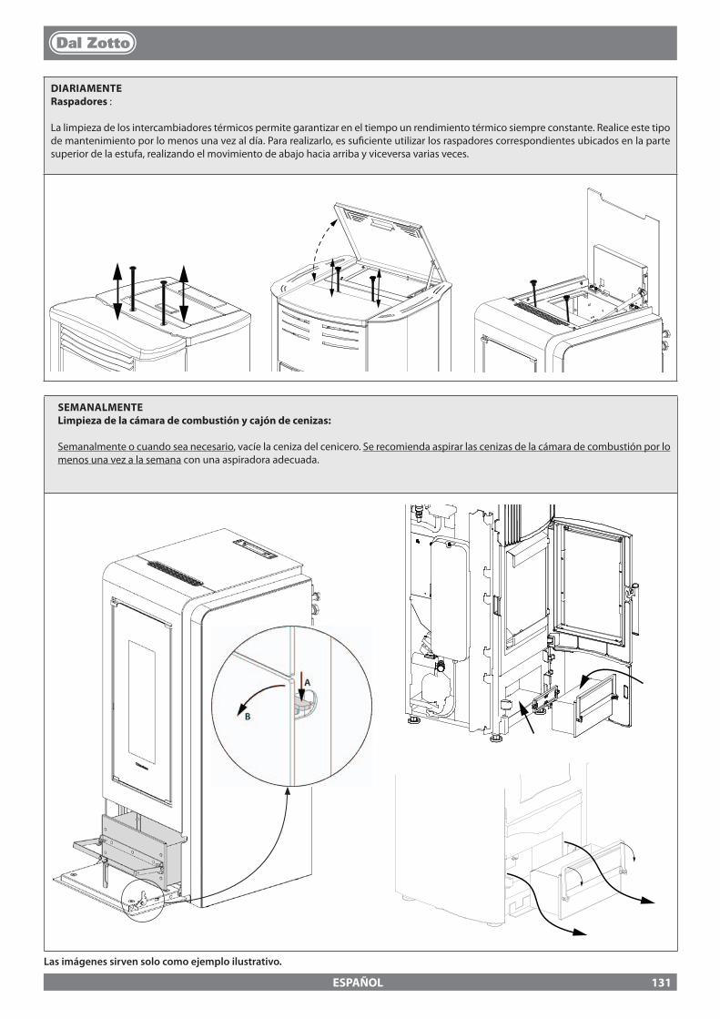
ESPAÑOL
DIARIAMENTERaspadores :
La limpieza de los intercambiadores térmicos permite garantizar en el tiempo un rendimiento térmico siempre constante. Realice este tipo de mantenimiento por lo menos una vez al día. Para realizarlo, es su�ciente utilizar los raspadores correspondientes ubicados en la parte superior de la estufa, realizando el movimiento de abajo hacia arriba y viceversa varias veces.
SEMANALMENTE Limpieza de la cámara de combustión y cajón de cenizas:
Semanalmente o cuando sea necesario, vacíe la ceniza del cenicero. Se recomienda aspirar las cenizas de la cámara de combustión por lo menos una vez a la semana con una aspiradora adecuada.
Las imágenes sirven solo como ejemplo ilustrativo.
131

ESPAÑOL
MANTENIMIENTO ORDINARIO REALIZADO POR TÉCNICOS HABILITADOS
El mantenimiento ordinario debe realizarse al menos una vez al año.El generador, utilizando pellet como combustible sólido, necesita de una intervención anual de mantenimiento ordinario que debe realizar un Técnico habilitado, utilizando exclusivamente repuestos originales.El incumplimiento puede poner en riesgo la seguridad del equipo y puede anular el derecho a las condiciones de garantía.Cumpliendo con los períodos de limpieza �jados, reservados al usuario, descritas en el manual de uso y mantenimiento, se garantiza la combustión correcta del generador a lo largo del tiempo, evitando posibles anomalías y/o mal funcionamientos que podrían necesitar más intervenciones por parte del técnico. Las solicitudes de intervenciones de mantenimiento ordinario no se incluyen en la garantía del producto.
JUNTAS DE LA PUERTA, CAJÓN DE CENIZA Y BRASERO
Las juntas garantizan la hermeticidad de la estufa y, por consiguiente, el funcionamiento correcto de la misma.Es preciso controlarlas periódicamente; si estuviesen desgastadas o dañadas, es preciso sustituirlas inmediatamente.Estas operaciones deberán ser realizadas por un técnico habilitado.
CONEXIÓN A LA CHIMENEA
Realice la limpieza y la aspiración del conducto que va a la chimenea una vez al año o, en todo caso, cuando sea necesario. Si existen tramos horizontales hay que eliminar los residuos para que no obstaculicen el pasaje de los humos.
PUESTA FUERA DE SERVICIO (FIN DE TEMPORADA)
Al �nal de cada temporada, antes de apagar la estufa, se recomienda vaciar completamente el depósito de pellet, aspirando posibles residuos de pellet y polvos, de su interior.SE RECOMIENDA NO DESCONECTAR EL GENERADOR DE LA RED ELÉCTRICA, PARA PERMITIR AL CIRCULADOR REALIDAR LOS CICLOS ANTIBLOQUEO NORMALES.El mantenimiento ordinario debe realizarse al menos una vez al año.
SI EL CABLE DE ALIMENTACIÓN ESTÁ ESTROPEADO, EL SERVICIO DE ASISTENCIA TÉCNICA O UNA PERSONA AUTORIZADA DEBERÁ REALIZAR LA SUSTITUCIÓN PARA PREVENIR RIESGOS.
MENSUALMENTE - JOLE IDRO 2.0
Elimine la ceniza depositada en la parte alta de la pared del hogar (vea �gura de abajo).
132
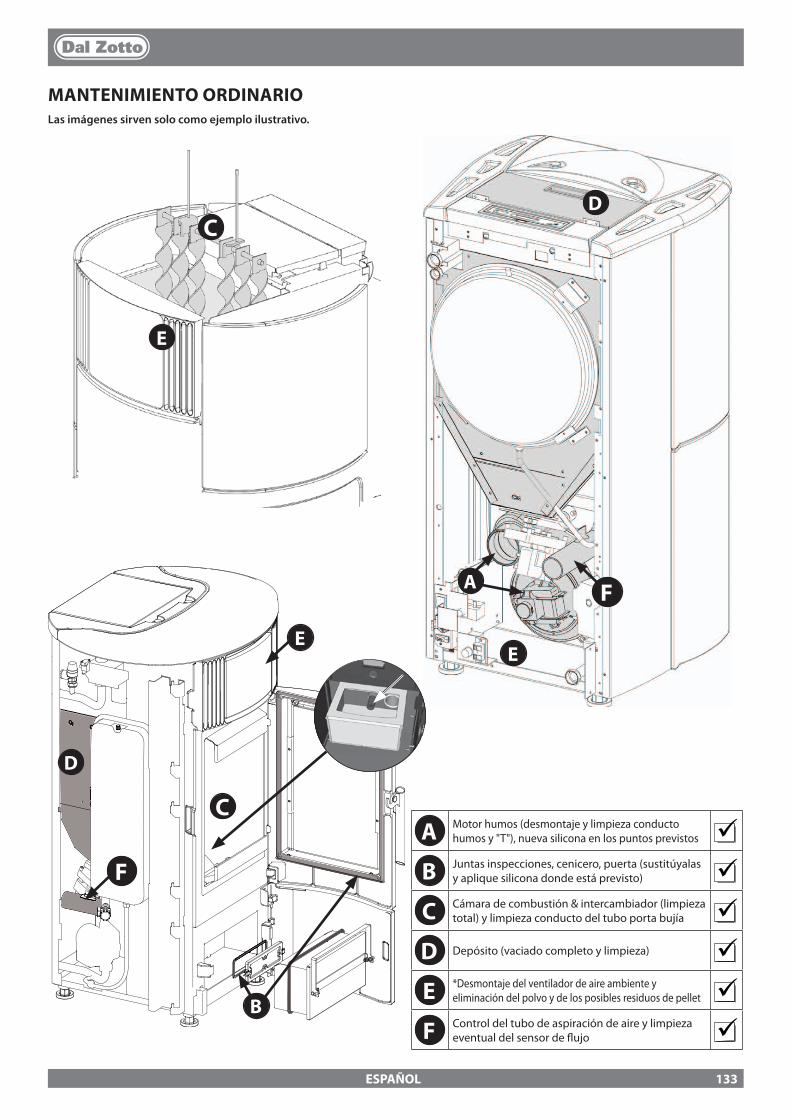
B
E
D
C
A
C
F
D
EE
F
ESPAÑOL
MANTENIMIENTO ORDINARIOLas imágenes sirven solo como ejemplo ilustrativo.
A Motor humos (desmontaje y limpieza conducto humos y "T"), nueva silicona en los puntos previstos
B Juntas inspecciones, cenicero, puerta (sustitúyalas y aplique silicona donde está previsto)
C Cámara de combustión & intercambiador (limpieza total) y limpieza conducto del tubo porta bujía
D Depósito (vaciado completo y limpieza) E *Desmontaje del ventilador de aire ambiente y
eliminación del polvo y de los posibles residuos de pellet F Control del tubo de aspiración de aire y limpieza
eventual del sensor de �ujo
133

ESPAÑOL
VISUALIZACIONESPANTALLA CAUSA
OFF Generador apagado
START La fase de puesta en marcha está en ejecución
CARGA PELLET Está en ejecución la carga continua del pellet durante el encendido
ENCENDIDO La fase de encendido está en ejecución
PUESTA EN MARCHA La fase de arranque está en ejecución
TRABAJO La fase de trabajo normal está en ejecución.
MODULACIÓN El generador está trabajando al mínimo
LIMPIEZA DEL BRASERO Se está ejecutando la limpieza del brasero
*LIMPIEZA DEL BRASERODEPRESIÓN
Se está realizando la limpieza del brasero - causa depresión insu�ciente.
LIMPIEZA FINAL La limpieza �nal está en ejecución
STAND-BY Generador apagado en espera de encendido, debido al termostato exterior
ESPERA ENFRIAMIENTO
Se intenta un nuevo encendido cuando el generador ha sido recién apagada. Cuando el generador realiza un apagado, es preciso esperar el apagado completo del motor de humos y a continuación realizar la limpieza del brasero. Solo una vez que se han realizado estas operaciones, es posible volver a encender el generador.
HOFF Generador apagado por temperatura del agua por encima del set con�gurado.
*T-AMB Visualiza la temperatura ambiente (en los modelos que lo prevén)
*T - OFF Generador apagado en espera de ser encendido dado que todas las solicitudes han sido satisfechas
ESPERA BLACK OUT
El generador se está enfriando después de una falta de corriente. Concluido el enfriamiento se encenderá nuevamente de modo automático
ANTIHIELO El funcionamiento antihielo está en ejecución ya que la t° H2O está por debajo del umbral programado en fábricaEl circulador se activa hasta que el agua alcanza el parámetro precon�gurado en fábrica +2 °C.
ANTIBLOQUEO La función antibloqueo del circulador está en ejecución (solo si el generador ha permanecido en estado de O� durante por lo menos 96 horas) el circulador se activa durante el tiempo preestablecido por el fabricante, de manera de evitar el bloqueo del mismo.
SOPLO AUTO Está activo el soplo automático
*BLOQUEO INTERCAMBIADOR La limpieza del intercambiador resulta bloqueada
ALARMASPANTALLA EXPLICACIÓN SOLUCIÓN
Indica la presencia de una alarma.
Encendida: indica la presencia de una alarma.Intermitente: Indica la desactivación del sensor de depresión.La alarma se puede resetear solo si se detuvo el motor de humos y si transcurrieron
15 minutos a partir de la visualización de la alarma, pulsando la tecla 1 durante 3 segundos.
ASPIRADOR AVERIADO
Avería en el motor de humos Póngase en contacto con el centro de asistencia
* en modelos predispuestos.
134

ESPAÑOL
* en modelos predispuestos.
SONDA DE HUMOS Avería sonda humos. Póngase en contacto con el centro de asistencia
HUMOS CALIENTES Temperatura de humos elevada Controle la carga pellet (véase "Regulación carga pellet"), en caso de que no se resuelva contacte con el técnico habilitado.
ALL CLEAN CHECH UP
La puerta no está cerrada correctamente.El cenicero no está cerrado correctamente.La cámara de combustión está sucia.El conducto de expulsión de humos está obstruido.
Controle que la puerta esté cerrada herméticamente.Controle que el cenicero esté cerrado herméticamente.Compruebe la limpieza del conducto de humos, del sensor del canal aire primario y de la cámara de combustión.
FALLO ENCENDIDO
El depósito de pellet está vacío.Calibración de la carga de pellet inadecuada.Bulbos termostáticos disparados.
Controle si hay pellet dentro del depósito.Regule el �ujo de pellet (véase "Regulación carga pellet").Controle los procedimientos descritos en el capítulo “Encendido”.Compruebe los termostatos a bulbos (consulte el capítulo Rearmes)
NO ENCENDIDO BLACK OUT
Falta de corriente durante la fase de encendido. Posicione la estufa en OFF mediante la tecla 1 y repita los procedimientos descritos en el capítulo “Encendido”.
FALTA PELLET El depósito de pellet está vacío.Carencia de carga de pellet.El motorreductor no carga pellet.
Controle si hay pellet dentro del depósito.Regule el a�ujo de pellet (vea “Regulación de la carga de pellet”).
ALARMA DEPRESIÓN
La puerta no está cerrada correctamente.El cenicero no está cerrado correctamente.La cámara de combustión está sucia.El conducto de expulsión de humos está obstruido o sucio.
Controle que la puerta esté cerrada herméticamente.Controle que el cenicero esté cerrado herméticamente.Controle la limpieza tanto del conducto de humos como de la cámara de combustión.
CAUDALÍMETRO AVERIADO
Sensor de �ujo defectuosoSensor desconectado Póngase en contacto con el centro de asistencia
SOBRETEMPERATURA H20
Aire en la instalaciónCirculación inadecuada
Posible aire en la instalación, purgue la instalaciónAusencia de circulación adecuada.Zona de seguridad ausente o inadecuada.El agua en el interior de la estufa ha superado los 95°C. Posible anomalía del circulador.Si el problema persiste, las operaciones de restablecimiento las debe efectuar un técnico autorizado.
* AVERÍA TRAMPILLA
La limpieza automática del brasero está bloqueada. Brasero sucio obstruidoLa puerta no está cerrada correctamente.
Controle que la puerta esté correctamente cerradaControle que el brasero esté libre y limpio.La limpieza automática del brasero está bloqueada.Si el problema persiste, contacte con el centro de asistencia
ALARMA-PRESIÓN H2O MÍN.
La presión de la instalación medida por el presostato es demasiado baja.
Posible aire en la instalación, purgue la instalaciónPosible carencia de agua o pérdidas debidas a anomalías en algún componente de la instalación.Si el problema persiste, contacte con el centro de asistencia
SONDA H2O Avería sonda H2O Póngase en contacto con el centro de asistencia
ALARMA PRESIÓN MÁX. H2O
La presión del agua superó el umbral máximo
Posible aire en la instalación, purgue la instalaciónCompruebe que los vasos de expansión no estén dañados o subdimensionadosControle que la instalación en frío esté cargada a la presión correctaSi el problema persiste, contacte con el centro de asistencia
* SENSOR PRESIÓN AVERIADO
Sensor diferencial de presión defectuoso, des-conectado o averiado.
Póngase en contacto con el centro de asistencia
* MANDO ESPIRAL Funcionamiento anómalo de la carga de pellet. Póngase en contacto con el centro de asistencia
* BLOQUEO ESPIRAL Funcionamiento anómalo del motor de pellet. Póngase en contacto con el centro de asistencia
* SONDA CALDERA Avería sonda caldera. Póngase en contacto con el centro de asistencia
* SONDA PUFFER Avería sonda caldera. Póngase en contacto con el centro de asistencia
* DEPÓSITO VACÍO
El depósito de pellet está vacío. La puerta no está cerrada correctamente.El cenicero no está cerrado correctamente.La cámara de combustión está sucia.El conducto de expulsión de humos está obstruido.
Controle si hay pellet dentro del depósito.Controle que la puerta esté cerrada herméticamente.Controle que el cenicero esté cerrado herméticamente.Compruebe la limpieza del conducto de humos, del sensor del canal aire primario y de la cámara de combustión.Póngase en contacto con el centro de asistencia
135
ESPAÑOL
1. Los productos DAL ZOTTO, marca comercial de La Nordica S.p.A., están garantizados, en el marco de la Comunidad Europea, durante un periodo de 24 meses desde la fecha de compra. La compra debe acreditarse mediante un documento �scalmente válido emitido por el distribuidor (recibo, factura o albarán de transporte) que identi�que el producto adquirido y la fecha de compra o entrega del mismo.
ATENCIÓN: esta garantía convencional no sustituye la garantía prevista por las normas europeas de protección de los consumidores.
La garantía convencional se entiende limitada al territorio italiano y a esos territorios de la Comunidad Europea cubiertos por el servicio de los centros de asistencia técnica autorizados (consulte la página web www.dalzotto.com).También debe entenderse delimitada territorialmente al país de residencia o domicilio del consumidor, que debe ser el mismo donde el vendedor del producto DAL ZOTTO tenga su sede legal o tenga domiciliada su actividad.Estas normas no se aplican en caso de compra del producto en el ámbito de actividades comerciales, empresariales o profesionales. En estos casos, la garantía del producto estará limitada a un periodo de 12 meses a partir de la fecha de compra.
GARANTÍA EN ITALIAQué hacer en caso de funcionamiento anómalo del producto: Consulte el manual de instrucciones para ver si la anomalía puede ser resuelta mediante la aplicación correcta de las funciones del producto en cuestión. Asegúrese de que el defecto se incluye en el tipo de anomalías cubiertas por la garantía; de lo contrario, el coste de la intervención correrá en su totalidad a cargo del consumidor. Cuando solicite la intervención del Servicio de Asistencia, indique siempre al Centro de Asistencia Autorizado: - la naturaleza del defecto - el modelo de su aparato - la dirección completa - el número de teléfono.
GARANTÍA EN EUROPAQué hacer en caso de funcionamiento anómalo del producto: Consulte el manual de instrucciones para ver si la anomalía puede ser resuelta mediante la aplicación correcta de las funciones del producto en cuestión. Asegúrese de que el defecto se incluye en el tipo de anomalías cubiertas por la garantía; de lo contrario, el coste de la intervención correrá en su totalidad a cargo del consumidor. Solicite la intervención del Servicio de Asistencia o la dirección del Centro de Asistencia Técnica Autorizado al vendedor, indicando siempre: la naturaleza del defecto, el modelo de su aparato, la dirección completa y el número de teléfono.
En caso de falta de conformidad que se mani�este en los 6 primeros meses de vida del producto, el consumidor tiene derecho a la reparación del defecto de forma gratuita. Del séptimo al vigésimo cuarto mes, en caso de que se compruebe una falta de conformidad, el consumidor tendrá que asumir el coste de la llamada, mientras que el vendedor seguirá haciéndose cargo del coste de la mano de obra y de posibles recambios funcionales utilizados.
2. Si el defecto observado es atribuible a condiciones o eventos externos, tales como, a modo de ejemplo y sin ser exhaustivos, la insu�ciente capacidad de las instalaciones; la instalación o mantenimiento erróneo llevado a cabo por personal que no cumple los requisitos establecidos por la legislación vigente en el país de residencia del consumidor; la negligencia; la imposibilidad de uso y el mantenimiento incorrecto por parte del consumidor respecto a lo indicado y recomendado en el manual de instrucciones del producto, que forma parte del contrato de venta, se anula la presente garantía. Tampoco se incluyen en esta garantía los daños sufridos por el producto en ausencia de causas comprobadas imputables a defectos de fabricación. Del mismo modo, quedan excluidos de la presente garantía los defectos atribuidos al funcionamiento incorrecto del conducto de humos, en virtud de la legislación vigente en el país en el momento de la compra, así como todos los defectos del producto debidos a desidia, rotura accidental, manipulación o daños en el transporte (arañazos, abolladuras, etc.), intervenciones realizadas por personal no autorizado y otros daños causados por intervenciones erróneas del consumidor en un intento de remediar la avería inicial. Se excluyen de la garantía los siguientes consumibles: juntas, cristales cerámicos o templados, revestimientos y rejillas de hierro fundido, materiales refractarios (p. ej., Nordiker u otros), componentes pintados, cromados o dorados, elementos de mayólica, manillas, brasero y componentes relacionados. En los productos Idro, el intercambiador de calor está excluido de la garantía si no se realiza un circuito anticondensación adecuado que garantice una temperatura de retorno del aparato de al menos 55 grados. Por lo general, se excluyen de la garantía todos los componentes externos al producto en los que el consumidor puede intervenir directamente durante el uso o mantenimiento, o que pueden estar sujetos a desgaste, o la formación de óxido y manchas en el acero debido al uso de productos de limpieza agresivos. En caso de indicar defectos no observados después en la fase de comprobación por parte de un técnico autorizado, la intervención correrá en su totalidad por cuenta del consumidor.
3. Si no fuera posible restablecer la conformidad mediante la reparación del producto/componente, se procederá a su sustitución, sin alterar el periodo de vencimiento y los términos de garantía adquiridos en el momento de la compra del producto/componente a sustituir.
4. DAL ZOTTO, marca comercial de La Nordica S.p.A., declina toda responsabilidad por posibles daños que puedan sufrir, directa o indirectamente, personas, animales y objetos como consecuencia del incumplimiento de todas las prescripciones indicadas en el correspondiente manual de instrucciones y relativas advertencias en cuestión de instalación, uso y mantenimiento del producto, que también puede descargarse de la página web.
5. Se excluyen de la garantía las intervenciones para el calibrado o regulación del producto en relación con el tipo de combustible u otro.
CONDICIONES DE GARANTÍA
136
ESPAÑOL
6. Si el producto fuese reparado en uno de los Centros de Asistencia Técnica Autorizados indicados por DAL ZOTTO y en caso de sustitución del producto, el transporte será gratuito. En los casos en los que el técnico fuera capaz de reparar el producto en el domicilio del usuario y este último se negara a ello, el transporte al laboratorio y la devolución estarán a su cargo.
7. Tras el periodo de 24 meses de garantía, cualquier intervención de reparación será abonada en su totalidad por el consumidor.
8. En caso de litigio, el órgano judicial de competencia será exclusivamente el foro de la sede legal de DAL ZOTTO (Vicenza-Italia).
ADVERTENCIAS ADICIONALES
� Utilice sólo el combustible recomendado por el fabricante. El producto no debe ser utilizado como incinerador. � No utilice el producto como escalera o estructura de apoyo. � No ponga a secar lencería sobre el producto. Posibles tendederos o similares deben mantenerse a una distancia adecuada del producto.
Peligro de incendio y daños al revestimiento. � Cualquier responsabilidad por un uso inadecuado del producto recae en su totalidad en el usuario, declinando el fabricante cualquier
responsabilidad civil y penal. � Cualquier tipo de manipulación o sustitución no autorizada de piezas no originales del producto puede resultar peligrosa para la
integridad del operario, declinando la empresa toda responsabilidad civil y penal. � Gran parte de las super�cies del producto están muy calientes (puerta, manilla, cristal, tubos de salida de humos, etc.). Así pues, debe
evitarse entrar en contacto con estas partes sin indumentaria de protección o medios adecuados, como por ejemplo guantes de protección térmica.
� Queda prohibido poner en funcionamiento el producto con la puerta abierta o el cristal roto. � El producto debe conectarse eléctricamente a una instalación provista de un sistema de tierra e�caz. � Apague el producto en caso de avería o mal funcionamiento. � La acumulación de pellet sin quemar en el quemador tras cada "fallo de encendido" debe retirarse antes de llevar a cabo un nuevo
encendido. Compruebe que el quemador esté limpio y bien colocado antes de volver a encenderlo. � No lave el producto con agua. El agua podría penetrar en el interior del aparato y dañar el aislamiento eléctrico, provocando descargas
eléctricas. � Las instalaciones que no cumplen las normas vigentes anularán la garantía del producto, así como el uso inadecuado y la falta de
mantenimiento según lo previsto por el fabricante.
137

138

139

IL FABBRICANTE SI RISERVA DI VARIARE LE CARATTERISTICHE E I DATI RIPORTATE NEL PRESENTE FASCICOLO IN QUALUNQUE MOMENTO E SENZA PREAVVISO, AL FINE DI MIGLIORARE I PROPRI PRODOTTI.
QUESTO MANUALE, PERTANTO, NON PUÒ ESSERE CONSIDERATO COME UN CONTRATTO NEI CONFRONTI DI TERZI.
THE MANUFACTURER RESERVES THE RIGHT TO VARY THE CHARACTERISTICS AND THE DATA REPORTED IN THIS PAMPHLET AT ANY MOMENT AND WITHOUT NOTICE, IN ORDER TO IMPROVE ITS PRODUCTS.
THIS MANUAL, THEREFORE, CANNOT BE REGARDED AS A CONTRACT TOWARDS OTHER PARTIES.
LE FABRICANT SE RÉSERVE LE DROIT DE MODIFIER LES CARACTÉRISTIQUES ET LES DONNÉES REPORTÉES DANS CE MANUEL À TOUT MOMENT ET SANS PRÉAVIS, DANS LE BUT D’AMÉLIORER SES PRODUITS.
PAR CONSÉQUENT, CE MANUEL NE PEUT PAS ÊTRE CONSIDÉRÉ COMME UN CONTRAT VIS-À-VIS DE TIERS.
DER HERSTELLER BEHÄLT SICH VOR, DIE IN DEN VORLIEGENDEN UNTERLAGEN WIEDERGEGEBENEN EIGENSCHAFTEN UND DATEN ZU JEDEM BELIEBIGEN ZEITPUNKT UND OHNE VORANKÜNDIGUNG ZU ÄNDERN, UM SEINE PRODUKTE ZU
VERBESSERN. DIESE ANLEITUNG KANN DAHER NICHT ALS VERTRAG DRITTEN GEGENÜBER ANGESEHEN WERDEN.
EL FABRICANTE SE RESERVA EL DERECHO A MODIFICAR LAS CARACTERÍSTICAS Y LOS DATOS CONTENIDOS EN EL PRESENTE MANUAL Y SIN PREVIO AVISO, CON EL OBJETIVO DE MEJORAR SUS PRODUCTOS.
POR LO TANTO ESTE MANUAL NO SE PUEDE CONSIDERAR COMO UN CONTRATO RESPECTO A TERCEROS.
PER CONOSCERE IL CENTRO ASSISTENZA PIU’ VICINO CONTATTARE IL PROPRIO RIVENDITORE O CONSULTARE IL SITO WWW.LANORDICA-EXTRAFLAME.COM
TO FIND THE SERVICE CENTRE NEAREST TO YOU CONTACT YOUR DEALER OR CONSULTTHE SITE WWW.LANORDICA-EXTRAFLAME.COM
POUR CONNAÎTRE LE CENTRE D’ASSISTANCE LE PLUS PROCHE CONTACTER VOTRE REVENDEUR OU CONSULTER LE SITE WWW.LANORDICA-EXTRAFLAME.COM
NEHMEN SIE, UM IHR NÄCHSTLIEGENDES KUNDENDIENSTZENTRUM ZU KENNEN, KONTAKT MIT IHREM HÄNDLER AUF ODER KONSULTIEREN SIE DIE WEBSEITE WWW.LANORDICA-EXTRAFLAME.COM
PARA CONOCER EL CENTRO DE ASISTENCIA MÁS CERCANO CONTACTAR A SU REVENDEDOR O CONSULTAR EL SITIO WWW.LANORDICA-EXTRAFLAME.COM
MADE IN ITALYdesign & production
004276835-000_MAN_UT.MARTAIDRO2.0_JOLEIDRO2.0_PROD05/05/2017
DAL ZOTTO - Via Summano, 104 , 36030 Montecchio Precalcino (VI) - ITALY +39.0445.804000 - +39.0445.804040 - [email protected] - www.lanordica-extra�ame.com