Manuale Tecnico Technical manual - · PDF fileManuale Tecnico / CAPITOLO 2 9...
84
ITALIANO ENGLISH 1 Manuale Tecnico Technical manual
Transcript of Manuale Tecnico Technical manual - · PDF fileManuale Tecnico / CAPITOLO 2 9...
ITALIANOENGLISH
1
Manuale TecnicoTechnical manual

2
3
ITALIANOENGLISH
Manuale Tecnico
Indice
Capitolo 1 Nozioni tecniche sugli impianti di climatizzazionepag. 6
Capitolo 2 Caratteristiche tecniche dei pannelli EUROPANpag. 8 2.1 Caratteristiche generali 2.2 Caratteristiche chimiche e fisiche
Densità Reazione al fuoco Assorbimento dell’acqua Temperatura di esercizio Permeabilità Conduttività termica Trasmittanza e resistenza termica Perdite di carico distribuite Fattore di attrito
Capitolo 3 Procedura di calcolo per il dimensionamento dei canalipag. 17
Capitolo 4 Metodologia di assemblaggio dei canalipag. 25 4.1 Linea “Praktico”
Capitolo 5 Metodologia di assemblaggio dei canalipag. 27 4.1 Linea “Classic”
Technical Manual
4
ITALIANOENGLISH
Index
Chapter 1 Outlines on the air conditioning systemspag. 28
Chapter 2 EUROPAN panel’s technical characteristicspag. 30 2.1 General characteristics 2.2 Chemical and physic characteristics
DensityFire reactionWater absorptionTemperature of usePermeabilityThermal conductivityTrasmittance and thermal resistanceDistributed load lossesFriction factor
Chapter 3 Procedure of calculation for the dimensioning of ductspag. 39
Chapter 4 Assembling methods of ductspag. 47 4.1 “Praktico” line
Chapter 5 Assembling methods of ductspag. 49 4.1 “Classic” line

Manuale Tecnico / Technical Manual
5
ITALIANOENGLISH
Indice / Index
Pag. 51 Guida all’installazione Installation guide
Pag. 53 Assemblaggio canale dritto linea “Praktico” Assembling a straight duct “Praktico” line
Pag. 56 Assemblaggio curva linea “Praktico” Assembling an elbow “Praktico” line
Pag. 59 Assemblaggio canale dritto linea “Classic” Assembling a straight duct “Classic” line
Pag. 61 Costruzione di un canale dritto Construction of a straight duct
Pag. 64 Costruzione di una curva linea “Classic” Construction of an elbow “Classic” line
Pag. 71 Punti salienti nell’assemblaggio dei canali Highlights of assembling ducts
Manuale Tecnico
Capitolo 16
ITALIANOENGLISH
NOZIONI TECNICHE SUGLI IMPIANTI DI CLIMATIZZAZIONE
Gli impianti di climatizzazione hanno il compito di regolare il microclima in un ambiente chiuso in modo da realizzare condizioni di benessere.
Il microclima è definito dal valore che assumono le quattro variabili ambientali:• Ta= temperatura dell’ aria,• T mr = temperatura media radiante,• V = velocità dell’aria,• Φ= umidità relativa dell’aria.
A queste si aggiunge la classe di purezza dell’aria n.
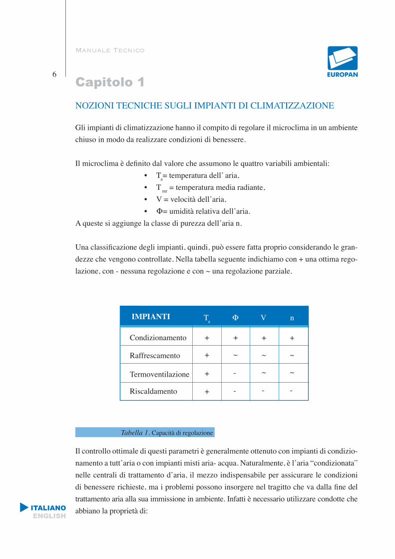
Una classificazione degli impianti, quindi, può essere fatta proprio considerando le gran-dezze che vengono controllate. Nella tabella seguente indichiamo con + una ottima rego-lazione, con - nessuna regolazione e con ~ una regolazione parziale.
Tabella 1. Capacità di regolazione
Il controllo ottimale di questi parametri è generalmente ottenuto con impianti di condizio-namento a tutt’aria o con impianti misti aria- acqua. Naturalmente, è l’aria “condizionata” nelle centrali di trattamento d’aria, il mezzo indispensabile per assicurare le condizioni di benessere richieste, ma i problemi possono insorgere nel tragitto che va dalla fine del trattamento aria alla sua immissione in ambiente. Infatti è necessario utilizzare condotte che abbiano la proprietà di:
IMPIANTI Ta Φ V n
Condizionamento
Raffrescamento
Termoventilazione
Riscaldamento
+
+
+
+
+
~
-
-
+
~
~
-
+
~
~
-
ITALIANOENGLISH
Manuale Tecnico / CAPITOLO 1
7
• Trasportare l’aria senza modificarne i parametri caratteristici durante il percorso.
• Assicurare che non si abbiano perdite di carico.
• Limitare la generazione e il trasferimento di rumore.
• Mantenere inalterate le caratteristiche per un periodo di tempo sufficientemente lungo.
Il sistema aeraulico realizzato con i pannelli prodotti da EUROPAN, oltre a garantire alti standard di sicurezza, assicura:
• Isolamento termico costante e continuo in ogni punto delle condotte.
• Ottima tenuta pneumatica.
• Facilità di assemblaggio dei canali perché i pannelli possono essere pretagliati, maneggevoli e pieghevoli.
• Gradevole estetica della superficie di finitura esterna che, può anche essere verniciata o rivestita a seconda dei gusti e delle esigenze.
• Nessun problema per l’ambiente, in quanto non si ha rilascio di agenti inquinanti e gas tossici.

ITALIANOENGLISH
Manuale Tecnico
Capitolo 28
CARATTERISTICHE GENERALI DEI PANNELLI
CARATTERISTICHE TECNICHE DEI PANNELLI EUROPAN
Le due linee di pannelli prodotti da EUROPAN sono “Classic” e “Praktico”.
La linea “Praktico” differisce dalla “Classic” per alcune peculiarità riguardanti esclu-sivamente i pannelli Praktico, infatti oltre ad essere pretagliati in fasce di misura standard, presentano delle nervature ogni 50 mm che, favorendone la piegabilità, li rendono particolarmente idonei per la realizzazione di curve e pezzi speciali diretta-mente in cantiere.
Le caratteristiche generali della due linee sono quelle di seguito riportate.
2.1 CARATTERISTICHE GENERALI
I pannelli, composti da schiume in poliuretano espanso rigido (PUR), sono ricoperti sui due lati da fogli in alluminio.
Il pannello Praktico viene prodotto in varie modalità di taglio (Standard, Special e Super) precalandrato ogni 50 mm per permettere la flessibilità in qualsiasi punto si voglia utilizzare e in differenti misure dai 150 mm ai 1200 mm con una tolleranza di ±2 mm. Lo spessore standard è di 20.5 mm e 30 mm con una tolleranza di ± 0.5 mm.
La lunghezza standard è di 3000 mm con una tolleranza di ± 5 mm.
Il pannello Classic presenta le stesse caratteristiche tecniche del pannello Praktico , ma ne differisce da quest’ultimo, poiché non è pretagliato e si presenta con una lastra di lunghezza standard pari a 4000 mm x 1200 mm con una tolleranza di ± 5 mm.
II materiale isolante che costituisce il pannello è un polimero di poliuretano espanso
(PUR) con celle chiuse ed è fisiologicamente e chimicamente inattivo, insolubile e non
metabolizzabile.
ITALIANOENGLISH
Manuale Tecnico / CAPITOLO 2
9
L’espansione della schiuma avviene tramite l’utilizzo di espandenti conformi a tutte le nor-mative ambientali vigenti (Regolamento CE N. 2037/2000 sulle sostanze che riducono lo strato di ozono e senza l’utilizzo di CFC e HCFC).
- Lo strato esterno è costituito da fogli in alluminio goffrato o liscio di spessore 80 micron o 200 micron, ricoperti da una lacca protettiva sulle facce esterne (circa 3 gr/m2).
In funzione delle applicazioni e del luogo in cui viene utilizzato il pannello, si consiglia la tipologia di alluminio da scegliere che può essere:
• liscio o goffrato
• con lacca antimicrobica
• di spessore 80 micron o 200 micron
La lacca antimicrobica è indicata per applicazioni in sale operatorie,ospedali, industrie ali-mentari e farmaceutiche.
L’alluminio con spessore 200 micron si utilizza per applicazioni outdoor, mentre lo spessore di alluminio 80 micron è particolarmente indicato in applicazioni indoor.
La confezione standard è costituita da 10 pannelli imballati con polietilene termore-stringente e con protezione nelle zone danneggiabili.
2.2 CARATTERISTICHE CHIMICHE E FISICHE
DENSITA’
La schiuma di poliuretano (PUR) ha una densità di 49 kg/m3 con una tolleranza di ± 2 kg/m3.
REAZIONE AL FUOCO
II pannello è classificato in Italia nella classe 0-1 secondo il D.M. 26/06/84 che certifica la reazione al fuoco e l’omologazione dei materiali ai fini della prevenzione incendi.
Inoltre, il pannello è stato sottoposto alla prova di reazione al fuoco secondo la normativa

ITALIANOENGLISH
Manuale Tecnico / CAPITOLO 2
10
EUROCLASSE UNI EN (13501-1:2007 ed è classificato B-s3, d0 ).
ASSORBIMENTO DELL’ACQUA
Il pannello, dopo 24 ore di immersione in acqua, ha un incremento di peso inferiore allo 0.05%.
TEMPERATURA DI ESERCIZIO
Il pannello può essere utilizzato fra +80°C e -30°C in esercizio continuo, senza mutare le sue caratteristiche.
PERMEABILITA’
La permeabilità al vapore dei fogli di alluminio, su entrambe le facce, tende all’infinito e pertanto il pannello è impermeabile al vapore.
CONDUTTIVITA’ TERMICA (In condizione di regime stazionario)
II concetto di isolamento sottintende l’impiego di materiali termoisolanti, che hanno, cioè, la proprietà e la funzione di ridurre la trasmissione del calore tra due ambienti a temperature diverse. La quantità di calore (Q, Kcal) che si trasmette è direttamente proporzionale alla superficie interessata (S, m2), alla differenza di temperatura tra le facce (T1, T2,
0C), al tempo (h), ed inversamente proporzionale allo spessore del materiale (s, m). E’ inoltre funzione di un coefficiente di proporzionalità ( λ, W/m0C) che varia a seconda della natura del materiale e dell’intervallo di temperatura nel quale avviene lo scambio termico.
Da qui la formula:
Il coefficiente di conduttività termica indicato con il simbolo λ, che individua la capacità di ciascun materiale a trasmettere il calore, si definisce come la quantità di calore che in un’ora, attraversa una superficie di 1 m2, avente lo spessore di 1m, quando la differenza di
Q= λ (T1-T2) Sh (Legge di Fourier)s
ITALIANOENGLISH
Manuale Tecnico / CAPITOLO 2
11
temperatura fra le due facce è di 1°C. Più basso è il valore della conduttività termica mag-giori sono le prestazioni isolanti del materiale. Nei materiali a struttura cellulare gli scambi termici avvengono principalmente per conduzione, che implica il contatto tra corpi a dif-ferenti temperature, il calore si trasferisce dal corpo caldo al corpo freddo mediante il tra-sferimento di energia cinetica. Per irraggiamento, il calore viene scambiato per emissione ed assorbimento di radiazione elettromagnetica escludendo pertanto la presenza di un mezzo. Nel caso del poliuretano gli scambi termici avvengono principalmente per conduzione, attraverso la fase gassosa all’interno delle celle e attraverso le pareti solide. Nel poliureta-no espanso rigido, usato per i pannelli EUROPAN, con densità di 49 kg/m3, il valore della conduttività termica è piuttosto basso. Come certificato dal Laboratorio Istituto Masini S.r.l., il coefficiente di conduttività termica del pannello prodotto dall’EUROPAN è
λ= 0,0183 ( W. m-1. K -1 )
TRASMITTANZA E RESISTENZA TERMICA
Si definisce trasmittanza (o conduttanza) termica (U) la quantità di calore che attraversa un materiale avente conduttività λ e spessore definito s per ogni metro quadro e per ogni ora, quando la differenza di temperatura è di 1°C.
II suo inverso si definisce resistenza termica (R).
I pannelli Europan sono materiali termoisolanti, in quanto hanno la proprietà di ridurre la trasmissione del calore tra due ambienti a temperature diverse. E’ noto che nell’art. 12 del D.P.R. n. 1052 del 28/06/77 si stabilisce che per il riscaldamento degli ambienti, i canali dell’aria che vengono posti in ambienti non riscaldati devono essere coibentati secondo le seguenti modalità: gli spessori dell’isolante per il coibente di riferimento che abbia condu-cibilità termica λ”=0.041( W. m-1. K-1 ) devono essere pari a 30 mm, nel caso di impiego di materiali di diversa natura, lo spessore suddetto va moltiplicato per il rapporto Pertanto lo spessore minimo necessario sarà dato: s = *30.
U= λ (W/m2K) s
R= s (m2K/W) λ
λ λ”λ
λ”
ITALIANOENGLISH
Manuale Tecnico / CAPITOLO 2
12
Quindi, essendo per il pannello Europan λ = 0,0183 ( W. m-1. K -1 ), ne segue che
s = *30 = *30 = 13.39 mm
e pertanto sono soddisfatte le condizioni di legge, risultando lo spessore del pannello pari a s = 20.5 mm chiaramente maggiore del valore trovato.
PERDITE DI CARICO DISTRIBUTE
Conoscere l’entità delle perdite di carico è fondamentale per chi deve progettare apparec-chiature o reti con fluido in movimento. In un tubo in cui scorre un fluido le perdite di carico corrispondono alle perdite di pressione: per calcolarle si può utilizzare l’equazione che esprime la velocità in funzione della variazione di pressione.
Δp = p1 - p2 = 8
in cui υ e μ sono rispettivamente la velocità media e la viscosità del fluido, L ed R la lunghezza del condotto e il raggio della sua sezione.
La perdita di carico è quindi direttamente proporzionale alla viscosità e alla velocità del fluido e alla lunghezza del tubo, ed è inversamente proporzionale al quadrato del raggio della sezione. Ad ogni metro di tubo corrisponde una certa perdita di carico; inoltre, più il fluido scorre veloce, più energia viene dissipata.
Poiché le perdite di carico risultano proporzionali alla lunghezza del condotto, si conside-rano distribuite lungo il condotto stesso e per questo vengono definite perdite distribuite.
FATTORE DI ATTRITO
La perdita di carico può anche essere espressa in funzione del numero di Reynolds, la cui espressione è
in cui ρ é la densità del fluido (in questo caso l’aria) e D il diametro della sezione del tubo.
λ λ”
0.01830.041
υ . L . μR2
ρ υ Dμ
(1)
Re=
ITALIANOENGLISH
Manuale Tecnico / CAPITOLO 2
13
Si consideri infatti la relazione (1) : moltiplicandola e dividendola per la velocità media υ per la densità ρ e sostituendo il raggio R con il diametro D, si ottiene:
Δρ = 32 υ . L . μ υ ρ = 64 L υ2 ρ
L è un rapporto adimensionale e v2
è l’energia cinetica a meno del fattore α. Il numero
puro 64 prende il nome di fattore di attrito che viene indicato con la lettera ξ. L’espres-
sione della perdita di carico risulta allora
Δρ = ξ L v2
Pd = v2
ρ
Indicando con : ξ= Fattore di attrito adimensionale, L = lunghezza del canale (m), D = diametro idraulico (m), Pd = pressione dinamica (Pa) corrispondente alla velocità media dell’aria nel canale
Δp= ξ ( L )Pd
Tale espressione non ha però validità generale: è esatta solo nel caso particolare di regi-me laminare completamente sviluppato,con tubo di sezione circolare e superficie liscia, quando cioè è valida la soluzione parabolica di Poiseuille. Il fattore d’attrito non è una costante : in tutti gli altri casi ξ assume un valore diverso da 64/Re. Il fattore di attrito è definito come quel numero puro che rende vera la relazione (3) e il suo valore, che viene ricavato sperimentalmente, dipende principalmente da tre fattori:
• il numero di Reynolds.
• la rugosità relativa: è un fattore che si potrebbe definire di forma e che dipende dalla possibilità che le pareti del tubo siano non lisce ma rugose. Si indica con il rapporto
D . D υ ρ Re D 2(2)
D D
Re
ρ D 2
(3)
2
D
Δp= perdita di pressione dovuta all’attrito
ITALIANOENGLISH
Manuale Tecnico / CAPITOLO 2
14
adimensionale ε dove ε e la rugosità, definita come l’altezza media delle asperità in millimetri sulla superficie della parete, e D il diametro in millimetri del tubo.
• un parametro che dipende dalla distanza x dal punto di imbocco del tubo ed è pari a x/D. La dipendenza da questo termine viene in genere trascurata. Infatti le perdite di carico sono funzione di x solo nella regione di ingresso del tubo, in quanto la velocità è funzione di x; tale dipendenza invece scompare nel regime sviluppato che, nel caso più frequente di regime turbolento, si instaura dopo solo 10 diametri.
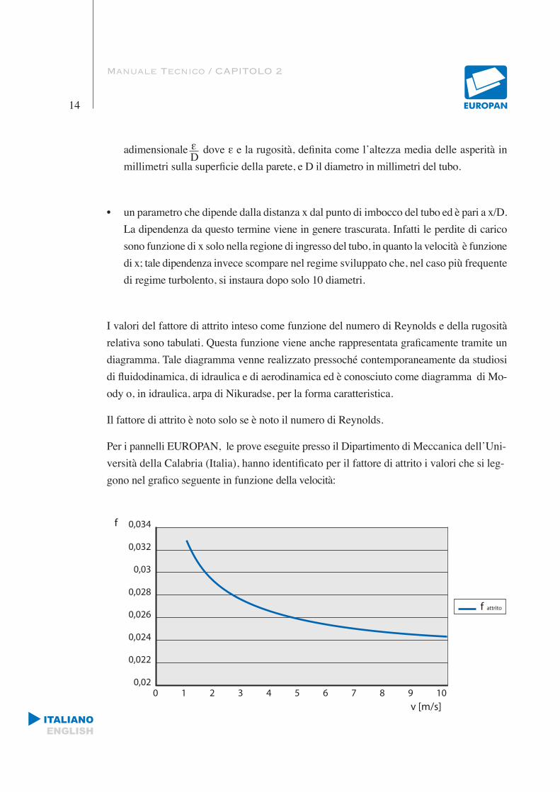
I valori del fattore di attrito inteso come funzione del numero di Reynolds e della rugosità relativa sono tabulati. Questa funzione viene anche rappresentata graficamente tramite un diagramma. Tale diagramma venne realizzato pressoché contemporaneamente da studiosi di fluidodinamica, di idraulica e di aerodinamica ed è conosciuto come diagramma di Mo-ody o, in idraulica, arpa di Nikuradse, per la forma caratteristica.
Il fattore di attrito è noto solo se è noto il numero di Reynolds.
Per i pannelli EUROPAN, le prove eseguite presso il Dipartimento di Meccanica dell’Uni-versità della Calabria (Italia), hanno identificato per il fattore di attrito i valori che si leg-gono nel grafico seguente in funzione della velocità:
D
ITALIANOENGLISH
Manuale Tecnico / CAPITOLO 2
15
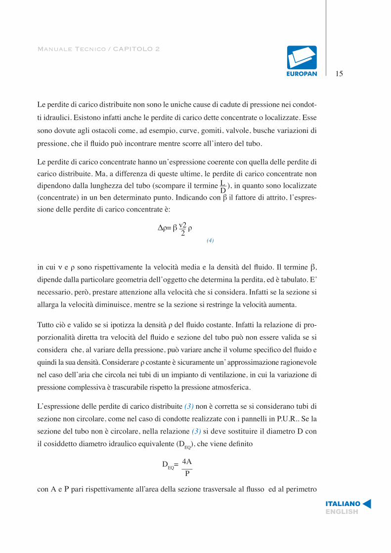
Le perdite di carico distribuite non sono le uniche cause di cadute di pressione nei condot-ti idraulici. Esistono infatti anche le perdite di carico dette concentrate o localizzate. Esse sono dovute agli ostacoli come, ad esempio, curve, gomiti, valvole, busche variazioni di pressione, che il fluido può incontrare mentre scorre all’intero del tubo.
Le perdite di carico concentrate hanno un’espressione coerente con quella delle perdite di carico distribuite. Ma, a differenza di queste ultime, le perdite di carico concentrate non dipendono dalla lunghezza del tubo (scompare il termine L ), in quanto sono localizzate (concentrate) in un ben determinato punto. Indicando con β il fattore di attrito, l’espres-sione delle perdite di carico concentrate è:
Δρ= β v2 ρ
in cui ν e ρ sono rispettivamente la velocità media e la densità del fluido. Il termine β, dipende dalla particolare geometria dell’oggetto che determina la perdita, ed è tabulato. E’ necessario, però, prestare attenzione alla velocità che si considera. Infatti se la sezione si allarga la velocità diminuisce, mentre se la sezione si restringe la velocità aumenta.
Tutto ciò e valido se si ipotizza la densità ρ del fluido costante. Infatti la relazione di pro-porzionalità diretta tra velocità del fluido e sezione del tubo può non essere valida se si considera che, al variare della pressione, può variare anche il volume specifico del fluido e quindi la sua densità. Considerare ρ costante è sicuramente un’ approssimazione ragionevole nel caso dell’aria che circola nei tubi di un impianto di ventilazione, in cui la variazione di pressione complessiva è trascurabile rispetto la pressione atmosferica.
L’espressione delle perdite di carico distribuite (3) non è corretta se si considerano tubi di sezione non circolare, come nel caso di condotte realizzate con i pannelli in P.U.R.. Se la sezione del tubo non è circolare, nella relazione (3) si deve sostituire il diametro D con il cosiddetto diametro idraulico equivalente (DEQ), che viene definito
DEQ= 4A
con A e Ρ pari rispettivamente all’area della sezione trasversale al flusso ed al perimetro
D
2(4)
P
ITALIANOENGLISH
Manuale Tecnico / CAPITOLO 2
16
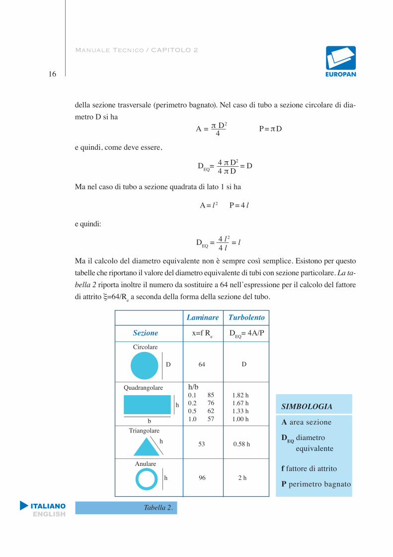
della sezione trasversale (perimetro bagnato). Nel caso di tubo a sezione circolare di dia-metro D si ha
A = π D2 P = π D
e quindi, come deve essere,
DEQ= 4 π D2 = D
Ma nel caso di tubo a sezione quadrata di lato 1 si ha
A = l 2 P = 4 l
e quindi:
DEQ = 4 l 2 = l
Ma il calcolo del diametro equivalente non è sempre così semplice. Esistono per questo tabelle che riportano il valore del diametro equivalente di tubi con sezione particolare. La ta-bella 2 riporta inoltre il numero da sostituire a 64 nell’espressione per il calcolo del fattore di attrito ξ=64/Re a seconda della forma della sezione del tubo.
Tabella 2.
4
4 π D
4 l
Laminare Turbolento
Sezione x=f Re DEQ= 4A/P
Circolare
D 64 D
Quadrangolare
h
b
h/b0.10.20.51.0
85766257
1.82 h1.67 h1.33 h1.00 h
Triangolareh 53 0.58 h
Anulare
h 96 2 h
SIMBOLOGIA
A area sezione
DEQ diametro
equivalente
f fattore di attrito
P perimetro bagnato
ITALIANOENGLISH
Manuale Tecnico
17
PROCEDURA DI CALCOLO PER IL DIMENSIONAMENTO DEI CANALI
Volendo effettuare il dimensionamento di un impianto è necessario conoscere le disper-sioni termiche globali dell’edificio che si considera:
• Le dispersioni che si verificano per trasmissione attraverso le strutture di tampona-mento opache (pareti, coperture, solai );
• Le dispersioni che si verificano per trasmissione attraverso le strutture di tampona-mento trasparenti (finestre, lucernari, grandi vetrate, ecc.);
• Le dispersioni dovute ai ricambi d’aria.
In via teorica, la potenza termica del generatore di calore dovrà risultare almeno uguale alla somma delle dispersioni termiche suddette. In realtà sarà ancora necessario verificare che il fabbisogno termico non sia superiore ai valori fissati per legge in base alle carat-teristiche fisiche dell’edificio (volume e superficie) e alle caratteristiche ambientali del luogo. In sintesi parametri da considerare saranno:
1. volume dell’edificio da riscaldare al lordo delle strutture di tamponamento;
2. superficie che delimita l’ambiente rispetto all’esterno;
3. gradi/giorno della località in cui è ubicato l’edificio in oggetto;
4. temperatura interna di progetto;
5. ricambi d’aria previsti;
6. rapporto superficie disperdente e volume riscaldato.
La procedura di calcolo per la valutazione del fabbisogno di piccoli ambienti è schema-tizzata nelle tabelle 3 e 4.
Capitolo 3

ITALIANOENGLISH
Manuale Tecnico / CAPITOLO 3
18
Tabella 3. Procedura di calcolo per la valutazione del fabbisogno termico invernale.
N. Voce Tipo Fattore x q.tà = Disperdimenti
Finestre
Muri esterni
Fissa, telaio legno o metalloApribile, telaio legnoApribile, Telaio metallo
Muratura pesanteMuratura leggeraInterrato
Vetro semplice248365309
Vetro doppio132248309
x.................m2=
0508513
252341-
501730-
≥1001322-
mm isolamento
x.................m2=x.................m2=
x.................m2=x.................m2=x.................m2=
Pareti versolocali nonriscaldati Muratura legno
04326
252112
50159
≥100127
mm isolamento
x.................m2=x.................m2=
Tetto
A falde o piano con soffittoTetto senza soffitto(usare l’area del soffitto per il calcolo dell’area del tetto a falde)(Per appartamento senza tetto usare il fattore per pavimento)
05085
252341
501730
1001626
mm isolamento
x.................m2=x.................m2=x.................m2=
Pavimento e soffitto Su terra
Su locale non riscaldatoEsposto
231550
x.................m2=x.................m2=x.................m2=
Sub-totale (Addizionare voci 1-5)
Fattoretemperaturaesterna
Temp. est.(°C)20100-5-10-20
180,000,280,590,740,891,20
Temp. int. (°C)20
0,000,330,640,790,941,25
220,070,380,690,840,991,30
240,120,430,740,901,051,35
x
Riscaldamentototale (Riga 6 x riga 7 (THC) THC = W Fattore ariacalda x 0,17Portata ariacalda (Riga 8 x riga 9)
(usare la portata d’aria di raffreddamentose gli impianti di riscaldamento e diraffreddamento usano lo stesso ventilatore) = m3/h
1
2
3
4
5
6
7
8
9
10
I valori indicati nelle tabelle 3 e 4 sono riportati a solo scopo esemplificativo.
I valori reali dipendono dalle diverse condizioni operative e possono essere determinati facendo riferimento a quanto riportato nelle tabelle UNI corrispondenti.
150917
ITALIANOENGLISH
Manuale Tecnico / CAPITOLO 3
19
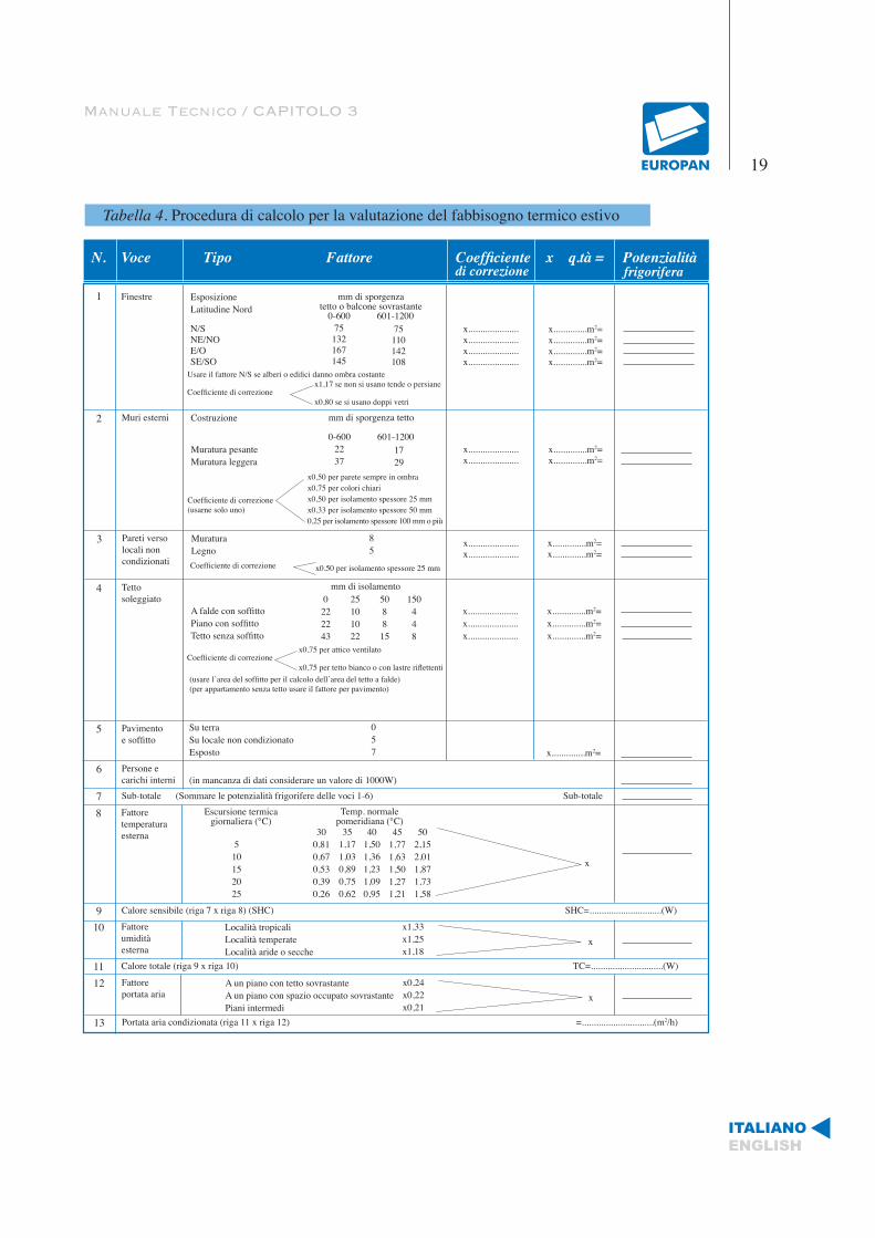
Tabella 4. Procedura di calcolo per la valutazione del fabbisogno termico estivo
N. Voce Tipo Fattore Coefficiente x q.tà = Potenzialità
Finestre EsposizioneLatitudine Nord
N/SNE/NOE/OSE/SO
mm di sporgenzatetto o balcone sovrastante
0-600 601-1200x.....................x.....................x.....................x.....................
x..............m2=x..............m2=x..............m2=x..............m2=
1
5
Usare il fattore N/S se alberi o edifici danno ombra costante
Coefficiente di correzionex1,17 se non si usano tende o persiane
x0,80 se si usano doppi vetri
75132167145
75110142108
di correzione frigorifera
Muri esterni Costruzione
Muratura pesanteMuratura leggera
mm di sporgenza tetto
0-600 601-1200
Coefficiente di correzione(usarne solo uno)
x0,50 per parete sempre in ombrax0,75 per colori chiarix0,50 per isolamento spessore 25 mmx0,33 per isolamento spessore 50 mm0,25 per isolamento spessore 100 mm o più
2237
1729
x.....................x.....................
x..............m2=x..............m2=
2
Pareti verso locali noncondizionati
MuraturaLegno
85
3
Coefficiente di correzione x0,50 per isolamento spessore 25 mm
x.....................x.....................
x..............m2=x..............m2=
Tettosoleggiato
A falde con soffittoPiano con soffittoTetto senza soffitto
4 mm di isolamento0
222243
25101022
508815
150448
Coefficiente di correzionex0,75 per attico ventilato
x0,75 per tetto bianco o con lastre riflettenti(usare l’area del soffitto per il calcolo dell’area del tetto a falde)(per appartamento senza tetto usare il fattore per pavimento)
x.....................x.....................x.....................
x..............m2=x..............m2=x..............m2=
Su terraSu locale non condizionatoEsposto
057
Pavimentoe soffitto
x..............m2=
6(in mancanza di dati considerare un valore di 1000W)
Persone ecarichi interni
7 Sub-totale (Sommare le potenzialità frigorifere delle voci 1-6) Sub-totale
8 Fattoretemperaturaesterna
Escursione termicagiornaliera (°C)
Temp. normalepomeridiana (°C)
300,810,670,530,390,26
351,171,030,890,750,62
401,501,361,231,090,95
451,771,631,501,271,21
502,152,011,871,731,58
510152025
x
9 Calore sensibile (riga 7 x riga 8) (SHC) SHC=..............................(W)
10 Località tropicaliLocalità temperateLocalità aride o secche
Fattoreumiditàesterna
x1,33x1,25x1,18
x
11 Calore totale (riga 9 x riga 10) TC=..............................(W)
12 A un piano con tetto sovrastanteA un piano con spazio occupato sovrastantePiani intermedi
Fattoreportata aria
x0,24x0,22x0,21
x
13 Portata aria condizionata (riga 11 x riga 12) =..............................(m2/h)

ITALIANOENGLISH
Manuale Tecnico / CAPITOLO 3
20
Ovviamente, il calcolo del carico termico dovrà essere fatto tenendo presenti le condizio-ni ambientali più sfavorevoli. E’ anche bene essere a conoscenza del volume di massima occupato dalle tubazioni, dai terminali scaldanti, dai camini e da eventuali canali che completano l’impianto.
Il carico termico globale determinato costituisce la base di proporzionamento dell’im-pianto.
Nei calcoli per il condizionamento dell’aria ci si riferisce normalmente alla pressione atmosferica con le caratteristiche seguenti:
• peso specifico: 1.2 kg/m3
• calore specifico: 0.24 Kcal/kg
Pertanto il calore specifico riferito al metro cubo risulta: (0.24*1.2)=0.29 Kcal/m3
Le variazioni del calore sensibile, stante il diagramma psicometrico dell’aria, seguono la formula seguente:
P= 0.29*Q*∆t
dove:
P = potenzialità termica sensibile in Kcal/h
Q = portata aria trattata in m3 /h
∆t= differenza tra la temperatura dell’aria prima e dopo la trasformazione
0.29= calore specifico dell’aria in Kcal/ m3
Il dimensionamento delle tubazioni dipende, dunque, dai seguenti fattori:
• Portata;
• Velocità dell’aria;
• Perdita di pressione ammissibile.
I circuiti di canali generalmente vengono classificati in base alla velocità dell’aria e alla
ITALIANOENGLISH
Manuale Tecnico / CAPITOLO 3
21
pressione di funzionamento. La classifica secondo la velocità si suddivide in sistemi a bassa velocità, quando la velocità nei canali non supera i 13 m/s, ed alta velocità, per valori compresi dell’aria tra 13 e 25 m/s. I canali di ripresa dell’aria vengono sempre dimensionati a bassa velocità.
La classificazione secondo la pressione si suddivide in sistemi a bassa pressione per va-lori fino a 900 Pa; a media pressione per valori da 900 a 1700 Pa e ad alta pressione per valori da 1700 fino a 3000 Pa. Nelle utenze medio-piccole si impiegano esclusivamente sistemi a bassa velocità e bassa pressione. Gli impianti ad alta velocità e ad alta pressio-ne, trovano, invece, applicazione negli edifici di grandi dimensioni, soprattutto di altezza elevata poiché consentono notevoli guadagni nelle sezioni di canali.
E’ ovvio che, perché l’aria possa muoversi entro i canali, la pressione totale del ventilato-re, che è la somma della pressione statica e della pressione dinamica, deve essere uguale alle perdite di carico complessive. Poiché le perdite di carico influenzano marcatamente il consumo di energia del ventilatore, è opportuno:
• Studiare lo sviluppo dei canali nel modo più lineare possibile.
• Ridurre al minimo il numero di gomiti e le variazioni di sezione.
• Evitare brusche variazioni di sezione.
• Posizionare l’Unità di Trattamento Aria, quando possibile, in posizione baricentrica rispetto al circuito.
Per la progettazione dei canali d’aria a bassa velocità si possono impiegare tre metodi diversi:
• Metodo a riduzione di velocità.
• Metodo a perdite di carico costanti.
• Metodo a recupero della pressione statica.
Il metodo a riduzione di velocità consiste nel dimensionare i canali in base a una velo-
ITALIANOENGLISH
Manuale Tecnico / CAPITOLO 3
22
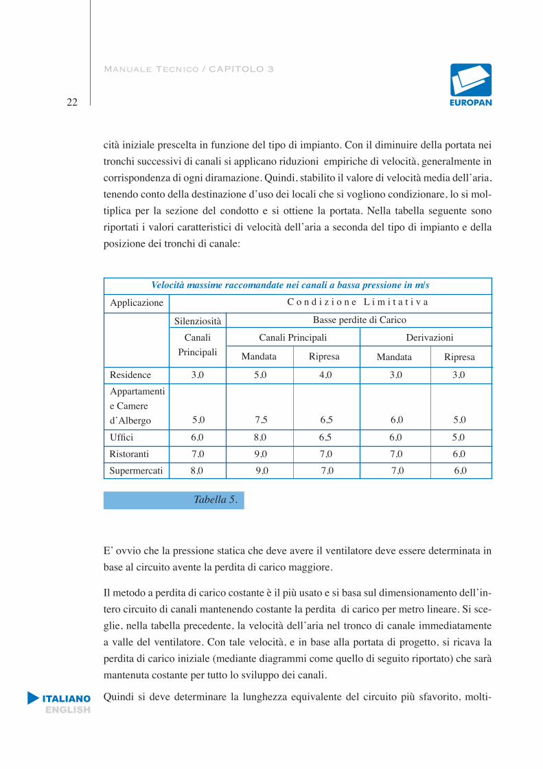
cità iniziale prescelta in funzione del tipo di impianto. Con il diminuire della portata nei tronchi successivi di canali si applicano riduzioni empiriche di velocità, generalmente in corrispondenza di ogni diramazione. Quindi, stabilito il valore di velocità media dell’aria, tenendo conto della destinazione d’uso dei locali che si vogliono condizionare, lo si mol-tiplica per la sezione del condotto e si ottiene la portata. Nella tabella seguente sono riportati i valori caratteristici di velocità dell’aria a seconda del tipo di impianto e della posizione dei tronchi di canale:
Tabella 5.
E’ ovvio che la pressione statica che deve avere il ventilatore deve essere determinata in base al circuito avente la perdita di carico maggiore.
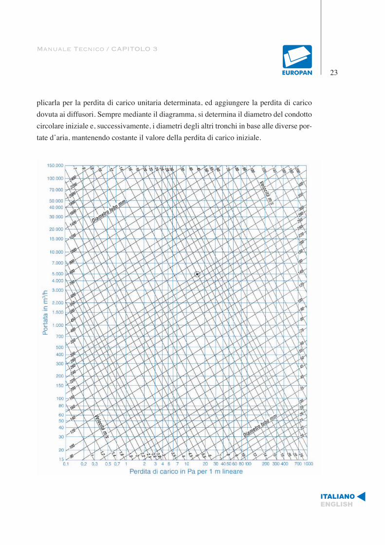
Il metodo a perdita di carico costante è il più usato e si basa sul dimensionamento dell’in-tero circuito di canali mantenendo costante la perdita di carico per metro lineare. Si sce-glie, nella tabella precedente, la velocità dell’aria nel tronco di canale immediatamente a valle del ventilatore. Con tale velocità, e in base alla portata di progetto, si ricava la perdita di carico iniziale (mediante diagrammi come quello di seguito riportato) che sarà mantenuta costante per tutto lo sviluppo dei canali.
Quindi si deve determinare la lunghezza equivalente del circuito più sfavorito, molti-
Velocità massime raccomandate nei canali a bassa pressione in m/s
C o n d i z i o n e L i m i t a t i v aApplicazione
Silenziosità Basse perdite di Carico
CanaliPrincipali
Canali Principali Derivazioni
Mandata Ripresa Mandata Ripresa
Residence 3,0 5,0 4,0 3,0 3,0Appartamentie Camered’Albergo 5,0 7,5 6,5 6,0 5,0
Uffici 6,0 8,0 6,5 6,0 5,0Ristoranti 7,0 9,0 7,0 7,0 6,0Supermercati 8,0 9,0 7,0 7,0 6,0
Manuale Tecnico / CAPITOLO 3
23
plicarla per la perdita di carico unitaria determinata, ed aggiungere la perdita di carico dovuta ai diffusori. Sempre mediante il diagramma, si determina il diametro del condotto circolare iniziale e, successivamente, i diametri degli altri tronchi in base alle diverse por-tate d’aria, mantenendo costante il valore della perdita di carico iniziale.
ITALIANOENGLISH

ITALIANOENGLISH
Manuale Tecnico / CAPITOLO 3
24
Diametri equivalenti Ø (1) di canali rettangolari a parità di perdita per attrito e di portata d’aria
Tabella 7.
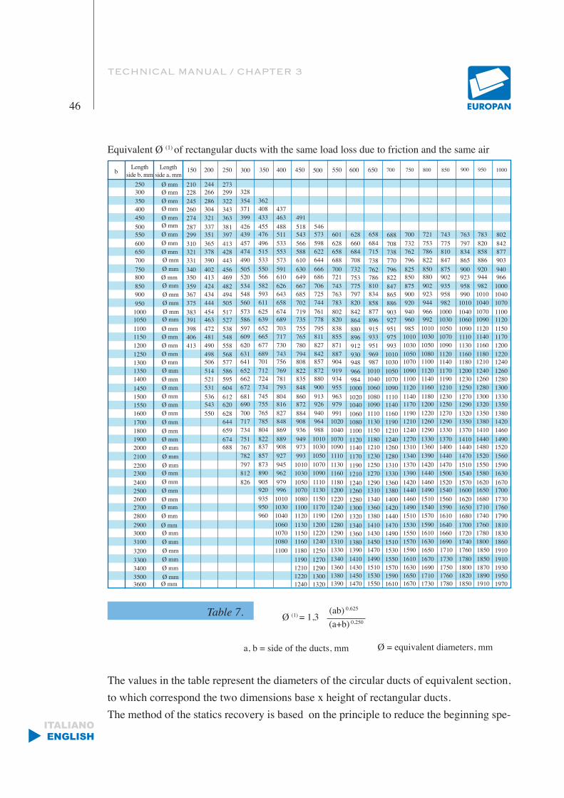
I valori nella tabella rappresentano i diametri dei canali circolari di sezione equivalente, a cui corrispondono le due dimensioni base x altezza di canali rettangolari.
Il metodo del recupero di statica si basa sul principio di ridurre la velocità iniziale in corri-
Ø (1) = 1,3(ab) 0,625
(a+b) 0,250
a, b = lati dei canali Ø = diametri equivalenti, mm
Lunghezzalato b, mm
Lunghezzalato a, mm
150 200 250 350 400 450 500 550 600 650 700 750 800 850 900 950 1000
250
500
300
550
350
600
400
650
450
700750
1000
800
1050
850
1100
900
1150
950
12001250
1500
1300
1550
1350
1600
1400
1700
1450
18001900
2400
2000
2500
2100
2600
2900
2200
2700
3000
2300
2800
3100
Ø mm
Ø mm
210
287
228
299
245
310
260
321
274
331340
383
350
391
359
398
367
406
375
413
244
337
266
351
286
365
304
378
321
390402
454
413
463
424
472
434
481
444
490498
536
506
543
514
550
521531
273
381
299
397
322
413
343
428
363
443456
517
469
527
482
538
494
548
505
558568
612
577
620
586
628
595
644
604
659674688
426
328
439
354
457
371
474
399
490505
573
520
586
534
597
548
609
560
620631
681
641
690
652
700
662
717
672
734751
826
767782797812
455476
362
496
408
515
433
533550
625
566
639
582
652
593
665
611
677689
745
701
755
712
765
724
785
734
804822
905
837
920
857
935
873
950
890
960
488511533
437
553
463
573591
674
610
689
626
703
643
717
658
730743
804
756
816
769
827
781
848
793
869889
979
908
996
927
1010
1060
945
1030
1070
962
1040
1080
518543566588
491
610630
719
649
735
667
755
685
765
702
780794
860
808
872
822
884
835
908
848
936949
1050
973
1070
993
1080
1130
1010
1100
1150
1030
1120
1160
546573598622644666
761
686
778
706
795
725
811
744
827842
913
857
926
872
940
880
964
900
9881010
1110
1030
1130
1050
1150
1200
1070
1170
1220
1090
1190
1240
601628658688700
802
721
820
743
838
763
855
783
871887
963
904
979
919
991
934
1020
955
10401070
1180
1090
1200
1110
1220
1280
1130
1240
1290
1160
1260
1310
628660684708732
842
753
864
775
880
797
896
820
912930
1020
948
1040
966
1060
984
1080
1000
11001120
1240
1140
1260
1170
1280
1340
1190
1300
1360
1210
1320
1380
658684715738762
877
786
896
810
915
834
933
858
951969
1080
987
1090
1010
1110
1040
1130
1060
11501180
1290
1210
1310
1230
1340
1410
1250
1360
1430
1270
1380
1450
688708738770796
903
822
927
847
951
865
975
886
9931010
1110
1030
1140
1050
1160
1070
1190
1090
12101240
1360
1260
1380
1280
1400
1470
1310
1420
1490
1330
1440
1510
700732762796825
940
850
960
875
985
900
1010
920
10301050
1140
1070
1170
1090
1190
1100
1210
1120
12401270
1420
1310
1440
1340
1460
1530
1370
1490
1550
1390
1510
1570
721753786822850
966
880
992
902
1010
923
1030
944
10501080
1180
1100
1200
1120
1220
1140
1260
1160
12901330
1460
1360
1490
1390
1510
1590
1420
1540
1610
1440
1570
1630
743775810847875
1000
902
1030
935
1050
958
1070
982
10901120
1230
1140
1250
1170
1270
1190
1290
1210
13301370
1520
1400
1540
1440
1560
1640
1470
1590
1660
1500
1610
1690
763797834865900
1040
923
1060
958
1090
990
1110
1010
11301160
1270
1180
1290
1200
1320
1230
1350
1250
13701410
1570
1440
1600
1470
1620
1700
1510
1650
1720
1540
1680
1740
783820858886920
1070
944
1090
982
1120
1010
1140
1040
11601180
1300
1210
1320
1240
1350
1260
1380
1280
14101440
1620
1480
1650
1520
1680
1760
1550
1710
1780
1580
1740
1800
802842877903940
1100
966
1120
1000
1150
1040
1170
1070
12001220
1330
1240
1350
1260
1380
1280
1420
1300
14601490
1670
1520
1700
1560
1730
1810
1590
1760
1830
1630
1790
1860
Ø mm
Ø mmØ mmØ mmØ mmØ mmØ mmØ mmØ mmØ mmØ mm
Ø mmØ mmØ mmØ mmØ mmØ mmØ mmØ mmØ mmØ mmØ mmØ mmØ mmØ mmØ mmØ mmØ mmØ mmØ mmØ mm
Ø mm
Ø mmØ mmØ mmØ mmØ mmØ mmØ mmØ mmØ mm
1100Ø mmØ mmØ mmØ mm
33003400
3200
3500
11801190121012201240
300
12501270129013001320
13301340136013801390
13901410143014501470
14701490151015301550
15301550157015901610
15901610163016501670
16501670169017101730
17101730175017601780
17601780180018201850
18501850187018901910
19101910193019501970
b
Ø mm3600
ITALIANOENGLISH
Manuale Tecnico
25
spondenza di ogni diffusore o diramazione. Si ottiene, così, una determinata conversione di pressione dinamica in pressione statica che serve a compensare esattamente le perdite di carico del tronco successivo.
In corrispondenza di tutti i diffusori e le diramazioni si ha, pertanto, la medesima pressio-ne statica. Ne consegue un impianto intrinsecamente bilanciato che non richiede disposi-tivi di taratura, con recupero della pressione statica del 75% del valore teorico.
La pressione statica del ventilatore dovrà vincere la perdita di carico fino alla prima di-ramazione o diffusore e assicurare la pressione necessaria per il funzionamento delle bocchette o dei diffusori.
Le perdite di carico a valle della prima diramazione o diffusore devono essere, invece, compensate dalla trasformazione della pressione dinamica in pressione statica.
Capitolo 4METODOLOGIA DI ASSEMBLAGGIO DEI CANALI
4.1 LINEA “PRAKTICO”
Nella linea Praktico la realizzazione di un qualsiasi canale segue un percorso ben preciso:
1. Identificazione fasce di pannelli di misure idonee per il canale da realizzare.
2. Incollaggio.
3. Assemblaggio e nastratura.
4. Applicazione profili.
La misura da intendersi per un canale (bxh) è la misura interna netta, perché è quella a cui si fa riferimento nel progetto per il passaggio dell’aria.
Per realizzare un canale bisogna, per prima cosa, identificare le fasce di pannelli che oc-corrono per la sua realizzazione. La lunghezza dei pannelli è 3000 mm, mentre le misure nette relative alla larghezza sono: 150 mm, 200 mm, 250 mm, 300 mm, 400 mm, 500 mm, 600 mm, 800 mm, 990 mm, 1160 mm, 1360 mm, 1560 mm, 1760 mm, 1960 mm.
ITALIANOENGLISH
Manuale Tecnico / CAPITOLO 4
26
In queste fasce di misure bisogna trovare i pannelli che occorrono per la realizzazione del canale. Ad esempio, se si vuole realizzare un canale di dimensione 800 x 1200 mm, le fasce che occorrono sono quelle da 800 e quelle da 1160 ( nel catalogo questa fascia è identificata con codice da 1200).
E’ anche possibile unire i pannelli mediante incollaggio e nastratura per ottenere dimen-sioni diverse da quelle previste dalle fasce.
Identificate le fasce di pannello occorrenti, si passa alla fase di incollaggio. Le superfici da incollare, chiaramente, devono risultare prive di polvere. Lungo tutti i tagli inclinati verrà distribuita uniformemente la colla. E’ conveniente disporre i pannelli uno sull’al-tro, a piramide, per stendere la colla lungo i bordi, in tal modo, ovviamente, si ottiene un risparmio di tempo e di energie. Si lascia asciugare la colla per circa 15\30 minuti (fino a che non risulti appiccicosa al tatto), e quindi si passa alla chiusura del pezzo.
Questa è la fase di assemblaggio. Naturalmente, l’ordine con cui il canale verrà assem-blato, varia in funzione della forma del canale. In genere si procede sempre dallo stesso bordo, in modo da dover rifilare gli eccessi delle varie facce solamente dalla parte opposta a quella di partenza. Chiudendo il canale, è opportuno assicurarsi che l’alluminio dei due pezzi, all’interno del canale, combaci perfettamente. Completato l’assemblaggio, si passa alla nastratura, che consiste nell’applicazione di nastro di alluminio in corrispondenza dei tagli. Ciò serve, oltre che per migliorare l’aspetto estetico del canale, soprattutto per ripristinare la barriera di vapore evitando l’eventuale formazione di condensa all’interno dell’espanso. Il nastro viene steso con l’ausilio di spatole.
L’unione fra i vari pezzi di canale, come anche l’inserimento, ad esempio, delle bocchette o delle serrande, avviene mediante l’applicazione di profili. I profili sono realizzati in lega di alluminio o in PVC. Tutti i profili devono essere tagliati alla misura interna del bordo in cui vanno inseriti meno 3 mm. I profili sono dotati di alette di diversa lunghezza. Sulle alette viene distribuita uniformemente la colla. Negli angoli, per ogni tipo di profilato, devono essere inserite delle squadrette di rinforzo, che conferiscono robustezza e rigidità al canale.
Dopo aver applicato i profili deve essere steso il silicone per sigillare le giunzioni longitu-dinali all’interno del canale. Il silicone serve, oltre che per assicurare una migliore tenuta, per incrementare la resistenza meccanica degli spigoli.
ITALIANOENGLISH
Manuale Tecnico
27
I tipi di canalizzazione che possono realizzarsi sono:• CANALE DRITTO
• CURVE
• RACCORDI
Ovviamente nei punti di maggiore sollecitazione possono prevedersi RINFORZI.
METODOLOGIA DI ASSEMBLAGGIO DEI CANALI
5.1 LINEA “CLASSIC”
Per la costruzione delle canalizzazioni mediante i pannelli Classic si utilizzano semplici attrezzature manuali.
TAGLIERINO TRADIZIONALE Taglierino con impugnatura ergonomica, che consente di tagliare i pannelli con estrema facilità e precisione. Le lame possono essere, a seconda dell’utensile inclinate a 45° a destra o a sinistra, oppure diritte e sporgono in modo da tagliare ambedue le lamine di rivestimento del pannello. I taglierini possono essere anche a doppia lama con le lame convergenti e non effettuano il taglio passante.
Per la realizzazione di un qualsiasi canale si segue un percorso ben preciso:• Tracciatura• Taglio• Incollaggio• Assemblaggio e nastratura• Applicazione profili.
I tipi di canalizzazioni che possono realizzarsi sono:
• CANALE DRITTO• CURVE• RACCORDI
Capitolo 5

TECHNICAL MANUAL
Chapter 128
ITALIANOENGLISH
PLANTS Ta Φ V n
Conditioning
Cooling
Thermoventilation
Heating
+
+
+
+
+
~
-
-
+
~
~
-
+
~
~
-
OUTLINES ON THE AIR CONDITIONING SYSTEMS
The air conditioning systems have the task of regulating the micro climate in a closed atmosphere so as to realize well-being conditions.
The microclimate is defined from the value that assume the four variable ones that accli-matizes them:
• Ta= temperature of the air,• T mr = radiating medium temperature,• V = velocity of the air,• Φ= relative humidity of the air.
At these we join the class of purity of the air n.
The classification of the systems, therefore, can be made considering the sizes that come controlled. In the following table we indicate with + optimal regulation, with- no regula-tion and ~ partial regulation.
Table 1. Ability to regulation
The optimal control of these parameters generally are obtained with systems of air con-ditioning or with mixed systems air-water. Naturally, “ the conditioned “ air in centers of air treatment, is the indispensable means in order to assure the demanded conditions of well-being, but the problems can rebel in the way that goes from the end of the air treatment to it’s breaking in atmosphere. In fact it is necessary to use ducts that have the property:

TECHNICAL MANUAL / CHAPTER 1
29
ITALIANOENGLISH
• To transport the air without any modification of the characteristic parameters during the distance.
• To assure that there aren’t loss of load.
• To limit the generation and the transfer of noise.
• Sufficiently to maintain unchanged the characteristics for a long period of time.
The realized air system with the panels produced by EUROPAN, beyond guarantees high standards of emergency, assures:
• Constant and continuous thermal Isolation in every point of the duct.
• Optimal pneumatic held.
• Facility to assemble the ducts because the panels can be precut, manageable and flexible.
• Good aesthetic of the external finish surface that, can also be painted or be covered second of the tastes and the requirements.
• No problem for the atmosphere, in how it does not release polluting agents or toxic gases.
TECHNICAL MANUAL
Chapter 230
ITALIANOENGLISH
GENERAL CHARACTERISTICS OF THE PANELS
EUROPAN PANEL’S TECHNICAL CHARACTERISTICS
The two lines of panels produced by EUROPAN are “Classic” and “Praktico”. The Prakti-co line differs from the “Classic” for some features regarding exclusively the Praktico panels, in fact are precut in strips of standard measures, and they are calendered every 50 millimeters that promotes the realization of elbows and special pieces, the general charac-teristic of the two lines are the following.
2.1 GENERAL CHARACTERISTICS
The panels made of expanded rigid foam in polyurethane (PUR), covered on both sides with sheets in aluminium.
The Praktico Panel is produced with different types of cuts (Standard, Special and Super) pre-calandered every 50 mm allowing flexibility in every point you want to use it and in different measures of width from 150 mm up to 1200 mm with maximum tolerance of 2 mm.The standard thickness is of 20.5 mm with tolerance of ± 0.5 mm.
Standard length is of 3.000 mm with tolerance of ± 5 mm.
The Classic panel presents the same technical features as the Praktico panel, but it differs itself from the Praktico panel, because it is not precut and in sheets of standard length equal to 4000 mm x 1200mm with a tolerance of ± 5 mm.
The insulating material that constitutes the panel is a polymer of thermo-insulating po-lyurethane rigid foam (PUR) with closed cells and it is physiologically and chemically inactive, insoluble and not metabolisable.
The expansion of the foam is made with the use of blowing agents in accordant to all the existing environmental standards (Regulation CE N.2037/2000 on the materials that reduce the ozone layer without using CFC and HCFC ).
TECHNICAL MANUAL / CHAPTER 2
31
ITALIANOENGLISH
The external coating is made from embossed or smooth aluminium sheets with thickness of 80 micron or 200 micron, covered with a protective lacquer on the external faces (rou-ghly 3 gr/m2).
In function of the applications and the places where is used the panel, is suggested the type of aluminium to choose that can be:
• smooth or embossed• with antimicrobial lacquer• of thickness 80 micron or 200 micron.
The antimicrobial lacquer is indicated for applications in operating rooms, hospitals, food and pharmaceutical industries.
The aluminium with thickness 200 micron is used for outdoor applications, while the aluminium is particularly used for indoor applications.
The standard packaging is constituted from 10 panels packed with polyethylene thermo-retractable and with suitable protection in the damageable zones.
2.2 CHEMICAL AND PHYSICS CHARACTERISTICS
DENSITYThe polyurethane foam (PUR) has a density of 49 kg/m3 with tolerance of ±2 kg/m3.
FIRE REACTIONThe panel is classified in Italy in class R.F. 0-1 according to D.M 26/06/84 certification of reaction to the fire and homologation of the materials to the aim of the prevention to set fire.Furthermore the panel has been subjected to a reaction to fire test according to standards EUROCLASS UNI EN 13501-1:2007 and it is classified B-s3, d0.

TECHNICAL MANUAL / CHAPTER 2
32
ITALIANOENGLISH
WATER ABSORPTION
The panel, after 24 hours that has been immersed in water; shows a weight increase infe-rior to 0,05% of its own weight.
TEMPERATURE OF USE
The panel can be used between the +80° C and the -30° C in continuous exercise, without substantial changes of the insulating characteristics.
PERMEABILITY
The permeability to the steam of the aluminium foil that covers the panel, on both the faces, verges to infinity so it is impermeable to the steam.
THERMAL CONDUCTIVITY (In stable conditions)
The isolation concept implicitly means the employment of thermo-insulating materials, that have the property and the function to reduce the transmission of the heat between two environments to various temperatures. The quantity of heat (Q, Kcal) that it is transmitted is directly proportional to the surface interested (S, m2), to the difference of temperature between face (T1, T2,
0C), to the time (h), and inversely proportional to the thickness of the material (s, m). It is moreover fun-ction of a proportionality coefficient, saying conductivity coefficient ( λ, W/m 0C) that varies second of the material and of the space out of temperature in which happens the transmission.
From here the formula :
The thermal conductivity coefficient indicated with the symbol λ, that identifies the ca-pacity of any material to transmit heat is defined as the quantity of heat that in one hour, crosses a surface of 1 m2 for a thickness of 1m, when the difference of temperature betwe-
Q= λ (T1-T2) Sh (Rule of Fourier)s

TECHNICAL MANUAL / CHAPTER 2
33
ITALIANOENGLISH
en the two faces is of 1°C. Lower is the value of the thermal conductivity greater are the performance of the insulating material. In the materials of cellular structure, the thermal exchanges happens mainly by conduction which implies the contact between bodies with different temperatures, the heat is transferred from hot to cold bodies through the transfer of kinetic energy. By irradiation the heat is exchanged for issue and absorption of electro-magnetic radiation excluding therefore the presence of a body. In the case of Polyuretha-ne the thermal exchanges mainly occur by conduction through the gas phases inside the cells and through the solid walls. Like certificate from the Laboratory of the Istituto Masini S.r.l., the coefficient of ther-mal conductivity of the panel produced by EUROPAN is
λ= 0,0183 ( W. m-1. K -1 )
TRANSMITTANCE AND THERMAL RESISTANCE Is defined thermal transmittance (or conductivity) (U) the quantity of heat that crosses through a material having conductivity λ and width defined s for every square meter and for every hour, when the difference of temperature is of 1° C
Its inverse is defined thermal resistance (R).
The quantity of heat that crosses a material with conductivity λ and thickness is defined s for every square meter and every hour, when the difference of temperatures is of l °C, is defined thermal conductance (λ). Its inverse is defined thermal resistance (U).EUROPAN panels are thermo-insulating material, in how much have the property to re-duce the transmission of the heat between two atmospheres to various temperatures. It is note that in the art. 12 of D.PR. n. 1052 of the 28/06/77 is settled down that for the heating of atmospheres the air ducts that are placed in atmospheres not heated have to be insulated in the following modes: the thickness of the insulator for the insulating of reference with thermal conductivity λ” = 0.041( W. m-1. K -1 ) must be equal to 30 millimeter, in the case
U= λ (W/m2K) s
R= s (m2K/W) λ
TECHNICAL MANUAL / CHAPTER 2
34
ITALIANOENGLISH
of employment of materials of various nature, the aforesaid thickness goes multiplied for the ratio . Therefore the minimal thickness necessary will be given: s= *30.
Therefore, -being for EUROPAN panel λ = 0,0183 ( W. m-1. K -1 ), it follows that
s = *30 = *30=13.39 mm
and therefore the law conditions are satisfied, turning out the thickness of the panel equal to s=20.5 mm clearly greater of the value found.
DISTRIBUTED LOAD LOSSES
To know the entity of load losses is fundamental for who must plan equipment or duct nets with fluid in motion. In a tube in which a fluid slides the load losses correspond to the losses of pressure: to calculate them the equation can be used that expresses the speed in function of the variation of pressure.
Δp = p1 - p2 = 8
(1)
In which v and µ they are respective the average speed and the viscosity of the fluid, L and R the length of the duct and the beam of its section.The load loss is, therefore, directly proportional to the viscosity and the speed of the fluid and the length of the tube and it is inversely proportional to the square of the beam of the section. To every meter of tube corresponds load loss; moreover; more the fluid slides faster; more energy comes dissipated. As load losses turn out proportional to the length of the duct, they are considered distributed along the same duct and for this they come defined distributed losses.
FRICTION FACTORLoad loss can also be expressed in function of the Reynolds number; whose expression is Re=
λ λ”
λ λ”
0.01830.041
λ λ”
υ . L . μR2
ρ υ Dμ

TECHNICAL MANUAL / CHAPTER 2
35
ITALIANOENGLISH
in which is the density of the fluid (in this case air) and D the diameter of the section of the tube. We consider; in fact, Relation (1): multiplying it and dividing it for the average speed v, for the density and replacing the beam R with the diameter D, we obtain:
Δρ = 32 υ . L . μ υ ρ = 64 L υ2 ρ
L is a dimension-less ratio and v2 is the kinetic energy less of the factor α. The pure
number 64 takes the name of the friction factor and comes indicated with letter ξ.
The expression of the load loss results
Δρ = ξ L v2
Pd = v2
ρ
Indicating with : Dp = loss of pressure due to friction, ξ= Dimensionless friction factor, L = Length of the duct (m), D = Hydraulic diameter (m), pd = Correspondent to the medium velocity of air in the duct.
Δp= ξ ( L )Pd
This expression has not got a general validity: is exact only in particular cases of comple-tely developed laminar flow with tube of circular section and smooth surface, so when is valid the solution parabolic of Poiseuille. The friction factor is not a constant : in all other cases ξ assumes a different value from 64/Re. The friction factor is defined like that pure number that gives back the relation (3) and its true value, that is experimentally obtained, mainly depends on three factors:• Reynolds number
• The relative roughness: it is a factor that could be defined of shape and that depends by possibility that the walls of the tube are not smooth but rough. It is indicated with
D . D υ ρ Re D 2(2)
D D
Re
ρ D 2
(3)
2
D
TECHNICAL MANUAL / CHAPTER 2
36
ITALIANOENGLISH
the dimension-less ratio ε , where ε is the roughness, defined like medium height of the roughness in millimeters on the surface of the wall, and D the diameter in milli-meters of the tube.
• A parameter that depends on distance x from the point of entrance of the tube and is equal to x/D. The dependency from this term generally comes neglected . In fact the load losses are function of x only in the region of income of the tube, the speed is a function of x; such dependency instead does not disappear in the developed running that, in the case more frequent than turbulent running, one establishes after only 10 diameters.
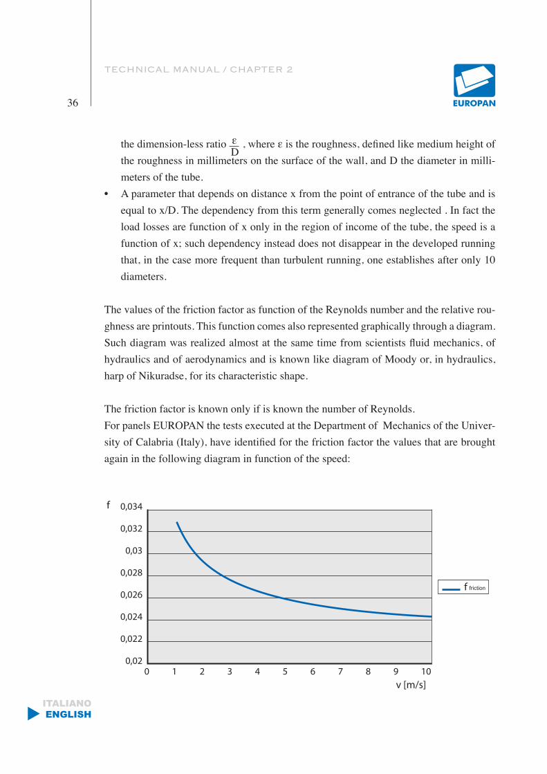
The values of the friction factor as function of the Reynolds number and the relative rou-ghness are printouts. This function comes also represented graphically through a diagram. Such diagram was realized almost at the same time from scientists fluid mechanics, of hydraulics and of aerodynamics and is known like diagram of Moody or, in hydraulics, harp of Nikuradse, for its characteristic shape.
The friction factor is known only if is known the number of Reynolds.For panels EUROPAN the tests executed at the Department of Mechanics of the Univer-sity of Calabria (Italy), have identified for the friction factor the values that are brought again in the following diagram in function of the speed:
D
friction

TECHNICAL MANUAL / CHAPTER 2
37
ITALIANOENGLISH
The distributed load losses are not the only causes of falls of pressure in the hydraulic ducts. Exist, in fact, also the load losses said concentrated or localized. They are due to the obstacles like, as an example, curves, elbows, valves, abrupt variations of pressure, that the fluid can meet while it slides inside the tube.The concentrated load losses have a coherent expression with the one of the distributed load loses. But, with the exception of these last ones, the concentrated load losses do not
depend on the length of the tube (the term disappears L ), in how much are localized (con-
centrated) in very determined points. Indicating with β the friction factor, the expression of the concentrated load losses is:
Δρ= β v2 ρ
The term β, depends from the particular shapes of the object that determines the loss and it is tabulated where v and ρ are respective the average speed and the density of the fluid. It is necessary to pay attention to the speed that is considered. In fact if the section is in-creased the speed diminishes, while if the section is shrunk the speed increases.
All that is valid if the density of the fluid is assumed constant. In fact the relation of pro-portionality directed between speed of the fluid and section of the tube cannot be valid if it is considered that varying of the pressure, can also vary the specific volume of the fluid and also its density .
To consider ρ constant is certainly a reasonable approximation in the case of the air that circulates in the tubes of a ventilation system, in which the variation of total pressure is negligible respect to the atmospheric pressure.The expression of the distributed load losses (3) is not correct if section tubes are consi-dered not circular, like in the case of ducts realized with the panels in PUR. If the section of the tube is not circular; in the relation (3) replaces the diameter D with the so-called hydraulic equivalent diameter, that comes defined (DEQ).
DEQ= 4A
with A and p equal respective to the area and the perimeter of the section.
D
2 (4)
P
TECHNICAL MANUAL / CHAPTER 2
38
ITALIANOENGLISH
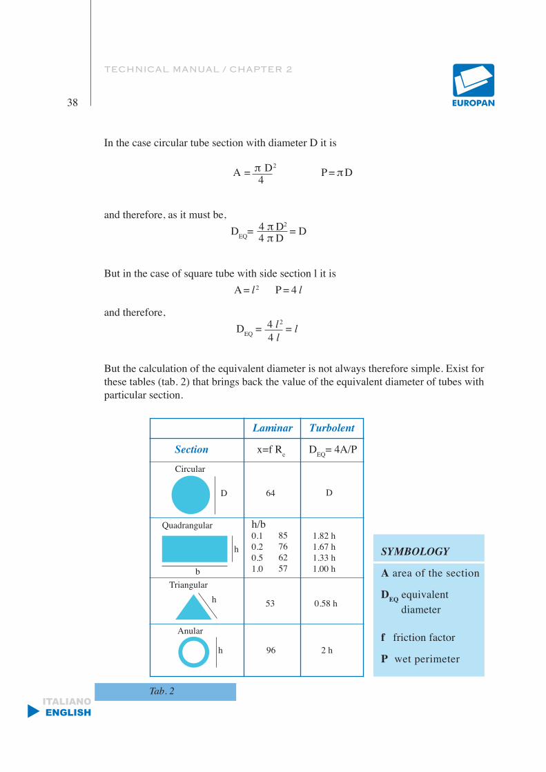
4
4 π D
4 l
Laminar Turbolent
Section x=f Re DEQ= 4A/P
Circular
D 64 D
Quadrangular
h
b
h/b0.10.20.51.0
85766257
1.82 h1.67 h1.33 h1.00 h
Triangularh 53 0.58 h
Anular
h 96 2 h
SYMBOLOGY
A area of the section
DEQ equivalent
diameter
f friction factor
P wet perimeter
In the case circular tube section with diameter D it is
A = π D2 P = π D
and therefore, as it must be, DEQ= 4 π D2 = D
But in the case of square tube with side section l it is A = l 2 P = 4 l
and therefore, DEQ = 4 l 2 = l
But the calculation of the equivalent diameter is not always therefore simple. Exist for these tables (tab. 2) that brings back the value of the equivalent diameter of tubes with particular section.
Tab. 2
TECHNICAL MANUAL
Chapter 339
ITALIANOENGLISH
PROCEDURE OF CALCULATION FOR THE DIMENSIONING OF DUCTS
Wanting to carry out the dimensioning of a plant first of all it is necessary to know the total thermal dispersion of the building that is considered:
• the dispersions that take place for transmission through the opaque structures of plug-ging (walls, covers, slab, etc.)
• the dispersions that take place for transmission through the transparent structures of plugging (windows, skylights, great windows, etc.)
• the dispersions for the air changing.
In theoretical way, the thermal power of the heat generator will have to turn out at least equal to the sum of the aforesaid thermal dispersions. In truth it will be still necessary to verify that the thermal requirements are not higher to the fixed values for Law in base to the physical characteristics of the building (volume and surface ) and to the surroundings characteristics of the place. In synthesis, the parameters to consider will be:
1. volume of the building to heat to the gross of the plugging structures;
2. surface that delimits the atmosphere in comparison outside;
3. degrees/day of the locality in which the building in object is located;
4. inner temperature of the plant;
5. previewed air changing;
6. relation dispersing surface and heated volume.
The procedure of calculation for the value of thermal requirements of small surrounding is outlined in tables 3 and 4.
TECHNICAL MANUAL / CHAPTER 3
40
ITALIANOENGLISH
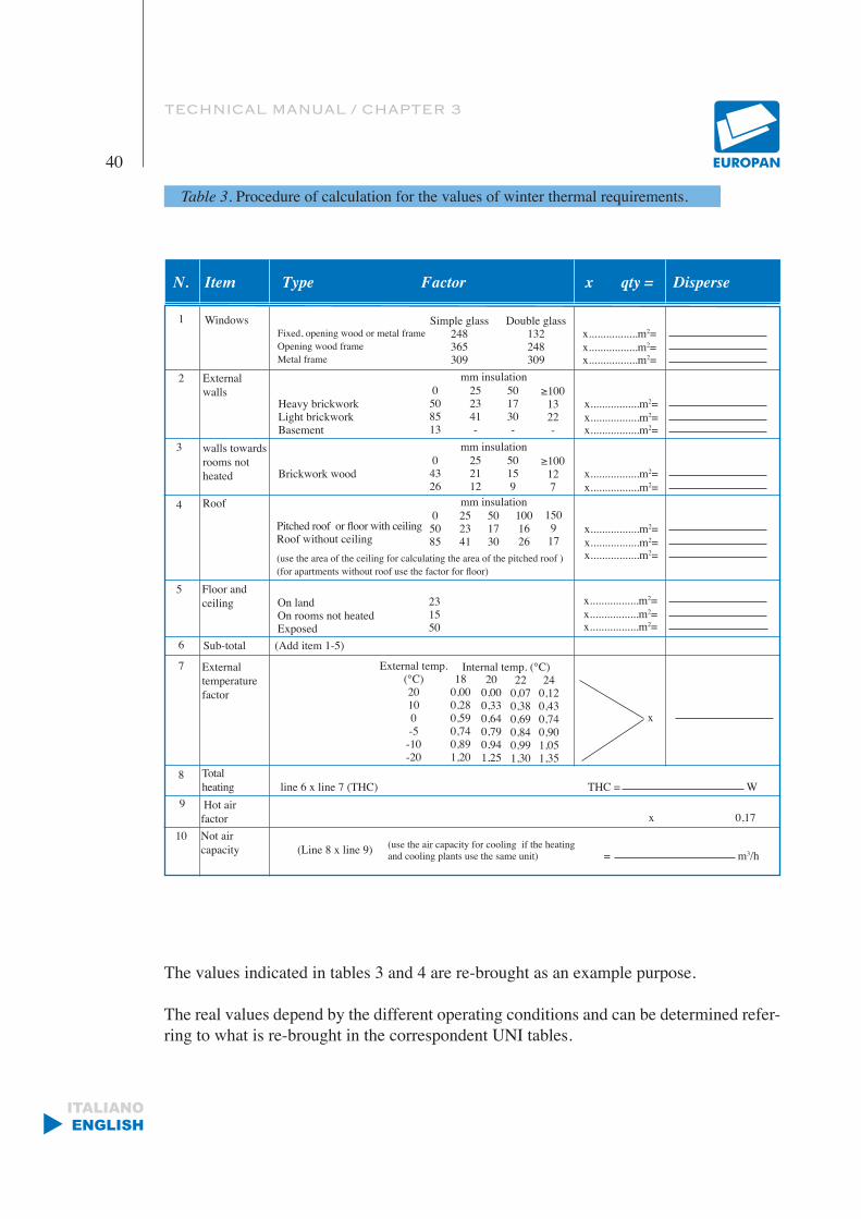
Table 3. Procedure of calculation for the values of winter thermal requirements.
N. Item Type Factor x qty = Disperse
Windows
External walls
Fixed, opening wood or metal frame Opening wood frameMetal frame
Heavy brickworkLight brickworkBasement
Simple glass248365309
Double glass132248309
x.................m2=
0508513
252341-
501730-
≥1001322-
mm insulation
x.................m2=x.................m2=
x.................m2=x.................m2=x.................m2=
walls towards rooms not heated Brickwork wood
04326
252112
50159
≥100127
mm insulation
x.................m2=x.................m2=
Roof
Pitched roof or floor with ceilingRoof without ceiling(use the area of the ceiling for calculating the area of the pitched roof )(for apartments without roof use the factor for floor)
05085
252341
501730
mm insulation
x.................m2=x.................m2=x.................m2=
Floor and ceiling On land
On rooms not heated Exposed
231550
x.................m2=x.................m2=x.................m2=
Sub-total (Add item 1-5)
External temperature factor
External temp.(°C)20100-5-10-20
180,000,280,590,740,891,20
Internal temp. (°C)20
0,000,330,640,790,941,25
220,070,380,690,840,991,30
240,120,430,740,901,051,35
x
Totalheating line 6 x line 7 (THC) THC = W Hot airfactor x 0,17Not aircapacity (Line 8 x line 9) (use the air capacity for cooling if the heating
and cooling plants use the same unit) = m3/h
1
2
3
4
5
6
7
8
9
10
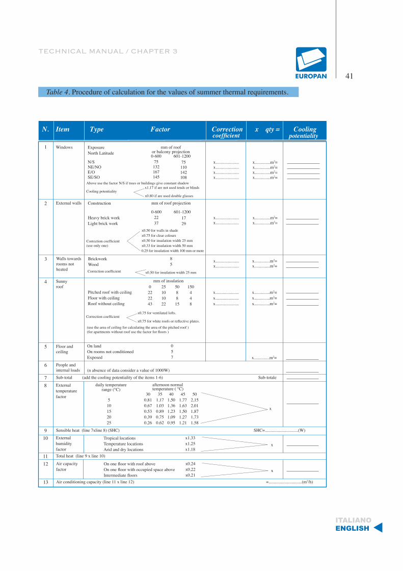
The values indicated in tables 3 and 4 are re-brought as an example purpose.
The real values depend by the different operating conditions and can be determined refer-ring to what is re-brought in the correspondent UNI tables.
1001626
150917
TECHNICAL MANUAL / CHAPTER 3
41
ITALIANOENGLISH
Table 4. Procedure of calculation for the values of summer thermal requirements.
N. Item Type Factor Correction x qty = Cooling
Windows ExposureNorth Latitude
N/SNE/NOE/OSE/SO
mm of roofor balcony projection0-600 601-1200
x.....................x.....................x.....................x.....................
x..............m2=x..............m2=x..............m2=x..............m2=
1
5
Above use the factor N/S if trees or buildings give constant shadow
Cooling potentialityx1,17 if are not used tends or blinds
x0,80 if are used double glasses
75132167145
75110142108
coefficient potentiality
External walls Construction
Heavy brick workLight brick work
mm of roof projection
0-600 601-1200
Correction coefficient(use only one)
x0,50 for walls in shadex0,75 for clear coloursx0,50 for insulation width 25 mmx0,33 for insulation width 50 mm0,25 for insulation width 100 mm or more
2237
1729
x.....................x.....................
x..............m2=x..............m2=
2
Walls towards rooms not heated
BrickworkWood
85
3
Correction coefficient x0,50 for insulation width 25 mm
x.....................x.....................
x..............m2=x..............m2=
Sunnyroof
Pitched roof with ceilingFloor with ceilingRoof without ceiling
4 mm of insulation0
222243
25101022
508815
150448
Correction coefficientx0,75 for ventilated lofts.
x0,75 for white roofs or reflective plates.(use the area of ceiling for calculating the area of the pitched roof )(for apartments without roof use the factor for floors )
x.....................x.....................x.....................
x..............m2=x..............m2=x..............m2=
On landOn rooms not conditionedExposed
057
Floor andceiling
x..............m2=
6(n absence of data consider a value of 1000W)
People andinternal loads
7 Sub-total (add the cooling potentiality of the items 1-6) Sub-totale
8 External temperature factor
daily temperature range (°C)
afternoon normal temperature ( °C)
300,810,670,530,390,26
351,171,030,890,750,62
401,501,361,231,090,95
451,771,631,501,271,21
502,152,011,871,731,58
510152025
x
9 Sensible heat (line 7xline 8) (SHC) SHC=..............................(W)
10 Tropical locationsTemperature locationsArid and dry locations
External humidity factor
x1,33x1,25x1,18
x
11 Total heat (line 9 x line 10)
12 On one floor with roof above On one floor with occupied space above Intermediate floors
Air capacity factor
x0,24x0,22x0,21
x
13 Air conditioning capacity (line 11 x line 12) =..............................(m2/h)
TECHNICAL MANUAL / CHAPTER 3
42
ITALIANOENGLISH
Obviously the calculation of the thermal cargo will have to be made holding present of the more unfavorable environmental conditions.Naturally, it is also well knowledge of the maximum volume occupied by the pipes, by the heating terminals, from fireplaces and eventual ducts that complete the plant.
The determined total thermal load constitutes the base of admeasurements of the system.
In the calculations for the conditioning of the air one refers to us normally to air at the atmospheric pressure with the following characteristics:
• Specific weight: 1.2 kg/m3
• Specific heat: 0.24 Kcal/kg
Therefore, the specific heat reported for the cubic meter results: (0.24*1.2)=0.29 Kcal/m3
The variations of the sensitive heat, being the psychrometer diagram of the air, observe the following formula:
P= 0.29*Q*∆t
where:
P = sensitive thermal potentiality in Kcal/h
Q = capacity air dealt in m3 /h
∆t = difference between the temperature of the air before and after the transformation
0.29 = specific heat of the air in Kcal/ m3
The dimensioning of the pipages depends, therefore , on following factors:
• Capacity of the air• Speed of the air• Loss of permissible pressure
The circuits of ducts are generally classified in base to the speed of the air and the pres-

TECHNICAL MANUAL / CHAPTER 3
43
ITALIANOENGLISH
sure of operation. The classification second the speed is subdivided in systems at low speed when the speed in the ducts does not exceed the 13 m/s, and high speed for values of the air included between 13 and 25 m/s. the ducts of resumption of the air always come dimensioned to low speed.
The classification second the pressure is subdivided in systems to low pressure for values until 900 Pa; to average pressure for values from 900 to 1700 Pa and high pressure for values from 1700 until 3000 Pa. In the medium-small users are employed exclusively systems at low speed and low pres-sure. The systems at high pressure find, instead, application in buildings of great dimen-sions, above all in buildings with high heights because they consent to earn sections of ducts.
It is obvious that, because the air can move within the ducts, the total pressure of the fan, that is the sum of the static pressure and the dynamic pressure, must be equal to the total losses of load. Since the losses of load in a marked manner influence on the consumption of energy of the fan, it is opportune:
• To study the development of the ducts in way that they are more linear as possible.
• To reduce as possible the number of elbows and the variations of section.
• To avoid abrupt variations of section.
• To position the Air conditioning unit, when possible, in a barycentric po-sition regarding the circuit.
For the planning of the air ducts to low speed three various methods can be employed:
• Method to speed reduction.
• Method to constant losses of load.
• Method of recovery of the static pressure.
The method to speed reduction consists to dimension the ducts based on a beginning spe-

TECHNICAL MANUAL / CHAPTER 3
44
ITALIANOENGLISH
ed pre-selected in function of the type of system.With the reducing of the capacity in the following logs of ducts empiric reductions of spe-ed are generally applied, in correspondence of every ramification. Therefore, established the value of average speed of the air, taking account of the destination of use of the rooms that are wanted to be conditioned, it has to be multiplied for the section of the duct and the capacity is obtained. In the following table are brought the characteristic values of speed of the air second the type of plant and the position of the logs of ducts:
Table 5.
It is clear that the static pressure that the ventilator has to have, will be determined based on the plant, having a greater loss of load.
The method to loss of constant load is used and is based on the dimensioning of the entire circuit of ducts maintaining constant the loss of load for linear meter. It is chosen, in the previous table, the speed of the air in the part of duct immediately after the fan. With such speed, and in base to the capacity of the plant, the beginning loss of load is obtained (by means of diagrams like the ones reported after) that it will be maintained constant for all the development of the ducts. Must be determined the length more equivalent of the disadvantageous circuit, multiply
Maximum velocity reccomendable ducts at low pressure in m/s
Limitative conditionApplication
Silence Low losses of load
Main ducts Main ducts Derivation
Throw Pickup Throw Pickup
Residence 3,0 5,0 4,0 3,0 3,0
Flat andHotel Rooms 5,0 7,5 6,5 6,0 5,0
Offices 6,0 8,0 6,5 6,0 5,0Restaurant 7,0 9,0 7,0 7,0 6,0Supermarket 8,0 9,0 7,0 7,0 6,0

TECHNICAL MANUAL / CHAPTER 3
45
ITALIANOENGLISH
Air
capa
city
in m
3 /h
Velocity m/s
Velocity m/s
Tube diameter mm
Tube diameter mm
Loss of load in Pa for 1 linear meter
it for the unitary loss of determined load, due to the diffusers. By means of the diagram, the diameter of the circular ducts is always determined and subsequently, the diameters of the other log based on the various air capacities, maintaining constant the beginning value of the loss of load.
TECHNICAL MANUAL / CHAPTER 3
46
ITALIANOENGLISH
Equivalent Ø (1) of rectangular ducts with the same load loss due to friction and the same airLength
side b, mmLength
side a, mm150 200 250 350 400 450 500 550 600 650 700 750 800 850 900 950 1000
250
500
300
550
350
600
400
650
450
700750
1000
800
1050
850
1100
900
1150
950
12001250
1500
1300
1550
1350
1600
1400
1700
1450
18001900
2400
2000
2500
2100
2600
2900
2200
2700
3000
2300
2800
3100
Ø mm
Ø mm
210
287
228
299
245
310
260
321
274
331340
383
350
391
359
398
367
406
375
413
244
337
266
351
286
365
304
378
321
390402
454
413
463
424
472
434
481
444
490498
536
506
543
514
550
521531
273
381
299
397
322
413
343
428
363
443456
517
469
527
482
538
494
548
505
558568
612
577
620
586
628
595
644
604
659674688
426
328
439
354
457
371
474
399
490505
573
520
586
534
597
548
609
560
620631
681
641
690
652
700
662
717
672
734751
826
767782797812
455476
362
496
408
515
433
533550
625
566
639
582
652
593
665
611
677689
745
701
755
712
765
724
785
734
804822
905
837
920
857
935
873
950
890
960
488511533
437
553
463
573591
674
610
689
626
703
643
717
658
730743
804
756
816
769
827
781
848
793
869889
979
908
996
927
1010
1060
945
1030
1070
962
1040
1080
518543566588
491
610630
719
649
735
667
755
685
765
702
780794
860
808
872
822
884
835
908
848
936949
1050
973
1070
993
1080
1130
1010
1100
1150
1030
1120
1160
546573598622644666
761
686
778
706
795
725
811
744
827842
913
857
926
872
940
880
964
900
9881010
1110
1030
1130
1050
1150
1200
1070
1170
1220
1090
1190
1240
601628658688700
802
721
820
743
838
763
855
783
871887
963
904
979
919
991
934
1020
955
10401070
1180
1090
1200
1110
1220
1280
1130
1240
1290
1160
1260
1310
628660684708732
842
753
864
775
880
797
896
820
912930
1020
948
1040
966
1060
984
1080
1000
11001120
1240
1140
1260
1170
1280
1340
1190
1300
1360
1210
1320
1380
658684715738762
877
786
896
810
915
834
933
858
951969
1080
987
1090
1010
1110
1040
1130
1060
11501180
1290
1210
1310
1230
1340
1410
1250
1360
1430
1270
1380
1450
688708738770796
903
822
927
847
951
865
975
886
9931010
1110
1030
1140
1050
1160
1070
1190
1090
12101240
1360
1260
1380
1280
1400
1470
1310
1420
1490
1330
1440
1510
700732762796825
940
850
960
875
985
900
1010
920
10301050
1140
1070
1170
1090
1190
1100
1210
1120
12401270
1420
1310
1440
1340
1460
1530
1370
1490
1550
1390
1510
1570
721753786822850
966
880
992
902
1010
923
1030
944
10501080
1180
1100
1200
1120
1220
1140
1260
1160
12901330
1460
1360
1490
1390
1510
1590
1420
1540
1610
1440
1570
1630
743775810847875
1000
902
1030
935
1050
958
1070
982
10901120
1230
1140
1250
1170
1270
1190
1290
1210
13301370
1520
1400
1540
1440
1560
1640
1470
1590
1660
1500
1610
1690
763797834865900
1040
923
1060
958
1090
990
1110
1010
11301160
1270
1180
1290
1200
1320
1230
1350
1250
13701410
1570
1440
1600
1470
1620
1700
1510
1650
1720
1540
1680
1740
783820858886920
1070
944
1090
982
1120
1010
1140
1040
11601180
1300
1210
1320
1240
1350
1260
1380
1280
14101440
1620
1480
1650
1520
1680
1760
1550
1710
1780
1580
1740
1800
802842877903940
1100
966
1120
1000
1150
1040
1170
1070
12001220
1330
1240
1350
1260
1380
1280
1420
1300
14601490
1670
1520
1700
1560
1730
1810
1590
1760
1830
1630
1790
1860
Ø mm
Ø mmØ mmØ mmØ mmØ mmØ mmØ mmØ mmØ mmØ mm
Ø mmØ mmØ mmØ mmØ mmØ mmØ mmØ mmØ mmØ mmØ mmØ mmØ mmØ mmØ mmØ mmØ mmØ mmØ mmØ mm
Ø mm
Ø mmØ mmØ mmØ mmØ mmØ mmØ mmØ mmØ mm
1100Ø mmØ mmØ mmØ mm
33003400
3200
3500
11801190121012201240
300
12501270129013001320
13301340136013801390
13901410143014501470
14701490151015301550
15301550157015901610
15901610163016501670
16501670169017101730
17101730175017601780
17601780180018201850
18501850187018901910
19101910193019501970
b
Table 7.
The values in the table represent the diameters of the circular ducts of equivalent section, to which correspond the two dimensions base x height of rectangular ducts.The method of the statics recovery is based on the principle to reduce the beginning spe-
Ø (1) = 1,3(ab) 0,625
(a+b) 0,250
a, b = side of the ducts, mm Ø = equivalent diameters, mm
3600 Ø mm
TECHNICAL MANUAL
47
ITALIANOENGLISH
ed in correspondence of every diffuser or ramification. It is obtained, therefore, a deter-mined conversion of the dynamic pressure in static pressure that is needed to compensate the losses of load of the following log.In correspondence of all the diffusers and the ramifications is obtained, therefore, the same static pressure. It is obtained a intrinsically balanced plant that it does not demand devices of calibration, with a recovery of the static pressure of 75% of the theoretical value.The static pressure of the fan will have to gain the loss of load until the first ramification or diffuser will have to assure the necessary pressure for the function of the grill or the diffusers.The losses of load at the valley of the first ramification or diffuser must be, instead, com-pensated from the transformation of the dynamic force in static pressure.
Chapter 4
ASSEMBLING METHODS OF DUCTS
“PRAKTICO” LINE
The realization of whichever ducts follows a very precise distance:
1. Identification strips of panels of suitable measures for the duct to be realized.
2. Gluing.
3. Assembling and taping.
4. Profiles application.
The measure to agree for a duct (bxh) is the clean inside measure, because it is the one that is referenced in the plan for the passage of the air.
To realize the ducts the first thing to identify are the strips of panels you need for the reali-zation. The length of the panels is 3000 mm while the clean measures relative to the width are: 150 mm, 200 mm, 250 mm, 300 mm, 400 mm, 500 mm, 600 mm, 800 mm, 990 mm,

TECHNICAL MANUAL / CHAPTER 4
48
ITALIANOENGLISH
1160 mm, 1360 mm, 1560 mm, 1760 mm, 1960 mm.
In these strips of measures you have to find the panels that are needed for the realization of the ducts. Example, if you want to realize a duct of dimensions 800 x1200 mm, the strips that are needed are of 800 and of 1160 (in the catalogue this strip is identified with code of 1200).
It is even possible to join the panels by gluing and taping to obtain dimensions different from the ones foreseen from the strips.Once identified the strips of panels that are needed, you pass to the gluing phase. The surfaces have to result without dust. Along the inclined cuts the glue has to be distributed evenly. It is convenient to dispose the panels one on the other like a pyramid, to spread the glue along the edges. In this way, obviously, you save time and energy. You leave it to dry for about 15\30 minutes (until doesn’t result sticky when you touch it), then you pass to the closing of the piece.
This is the assemble phase. Naturally the order in which the duct will be jointed, varies in function of the duct’s form. Generally we proceed always from the same edge, so we can trim the excess of the varied faces only at the side opposite the starting side. Closing the duct it is opportune to assure that the aluminium inside the duct of both pieces match. To complete the assemblage, you can pass to the taping that consists in the application of aluminium tape where the cuts have been done. This serves to improve the outside appearance of the duct, above all to re-establish the barrier of steam avoiding the eventual formation of condensate inside the expanded rigid foam. The tape goes extended with help of a spatula. The union of different pieces of the duct, like the insertion, at example of plenum grills or air lock. Happens by means of the application of the profiles.
The profiles are realized in aluminium or PVC. All the profiles have to be cut equal to the inside measure of the edges less 3mm where they go inserted. The profiles have fins of different lengths. On the fins comes uniformly distributed the glue. In the angles, for each type of profile, have to be inserted reinforcement angles, that give sturdiness and rigidity to the duct. After you have to put the silicone to seal the longitudinal joints inside the ducts. The silicone is needed not only to assure a better holding even to increase the mechanical resistance of the corners.
TECHNICAL MANUAL
49
ITALIANOENGLISH
The types of ducts, that can be realized, are:• STRAIGHT DUCTS• ELBOWS• CONNECTIONS
Obviously in the greater points of solicitation they can be previewed REINFORCES.
Capitolo 5
ASSEMBLING DUCTS
“CLASSIC” LINE
For the construction of ducts by means of Classic panels are used simple manual equip-ments.
TRADITIONAL CUTTER
Cutter with ergonomic grip, that it concurs to cut the panels with extreme facility and precision. The blades can be, second of the tool, tilted to 45° right or on the left, or straight and they jut out so to cut both sheets of aluminum that cover the panel. There are also cutters with double blades that have convergent blades and they do not carry out the passing cut.
For the realization of whichever ducts we follow a very precise route:
• Marking.
• Cutting.
• Gluing.
• Assembling and taping.
• Profiles application.
The types of ducts, that can be realized, are:
• STRAIGHT DUCTS
• ELBOWS
• CONNECTIONS

50
ITALIANOENGLISH
Manuale Tecnico / Technical Manual
Guida all’installazioneInstallation guide
51

52
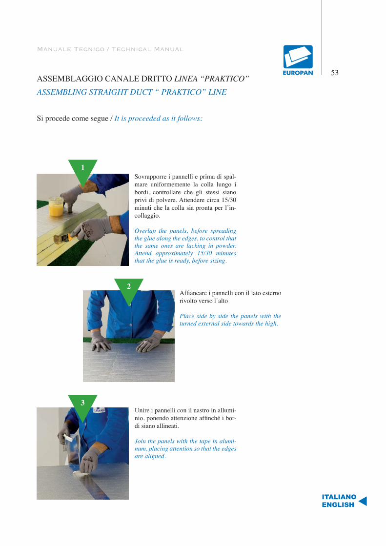
Manuale Tecnico / Technical Manual
ASSEMBLAGGIO CANALE DRITTO LINEA “PRAKTICO”ASSEMBLING STRAIGHT DUCT “ PRAKTICO” LINE
Si procede come segue / It is proceeded as it follows:
53
ITALIANOENGLISH
1Sovrapporre i pannelli e prima di spal-mare uniformemente la colla lungo i bordi, controllare che gli stessi siano privi di polvere. Attendere circa 15/30 minuti che la colla sia pronta per l’in-collaggio.
Overlap the panels, before spreading the glue along the edges, to control that the same ones are lacking in powder. Attend approximately 15/30 minutes that the glue is ready, before sizing.
2Affiancare i pannelli con il lato esterno rivolto verso l’alto
Place side by side the panels with the turned external side towards the high.
3Unire i pannelli con il nastro in allumi-nio, ponendo attenzione affinché i bor-di siano allineati.
Join the panels with the tape in alumi-num, placing attention so that the edges are aligned.
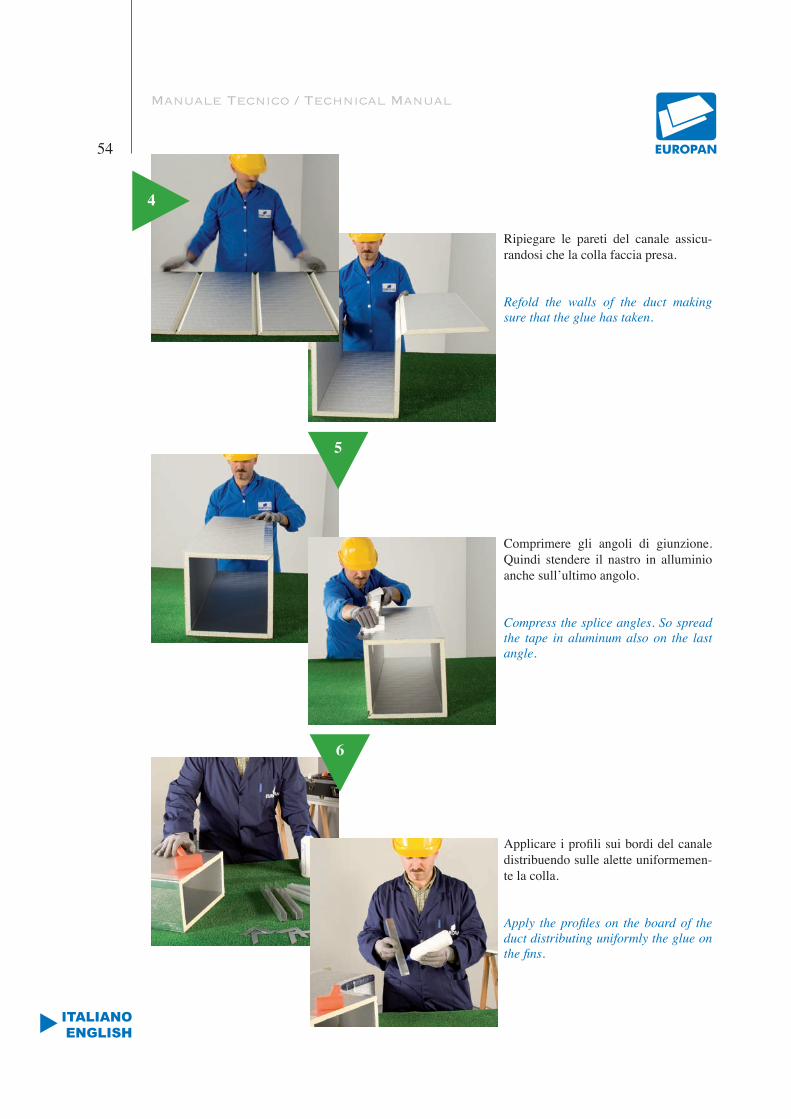
Manuale Tecnico / Technical Manual
54
ITALIANOENGLISH
Ripiegare le pareti del canale assicu-randosi che la colla faccia presa.
Refold the walls of the duct making sure that the glue has taken.
5
4
Comprimere gli angoli di giunzione. Quindi stendere il nastro in alluminio anche sull’ultimo angolo.
Compress the splice angles. So spread the tape in aluminum also on the last angle.
6
Applicare i profili sui bordi del canale distribuendo sulle alette uniformemen-te la colla.
Apply the profiles on the board of the duct distributing uniformly the glue on the fins.
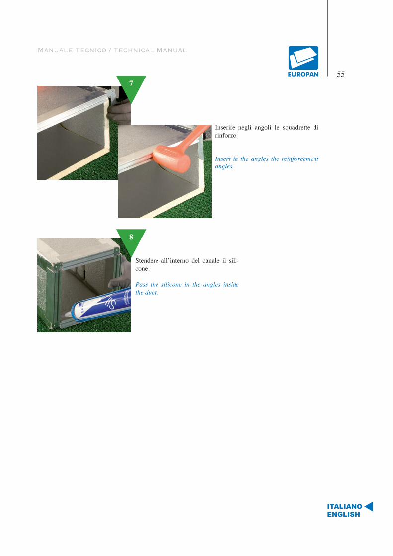
Manuale Tecnico / Technical Manual
55
ITALIANOENGLISH
4
Inserire negli angoli le squadrette di rinforzo.
Insert in the angles the reinforcement angles
Stendere all’interno del canale il sili-cone.
Pass the silicone in the angles inside the duct.
7
8
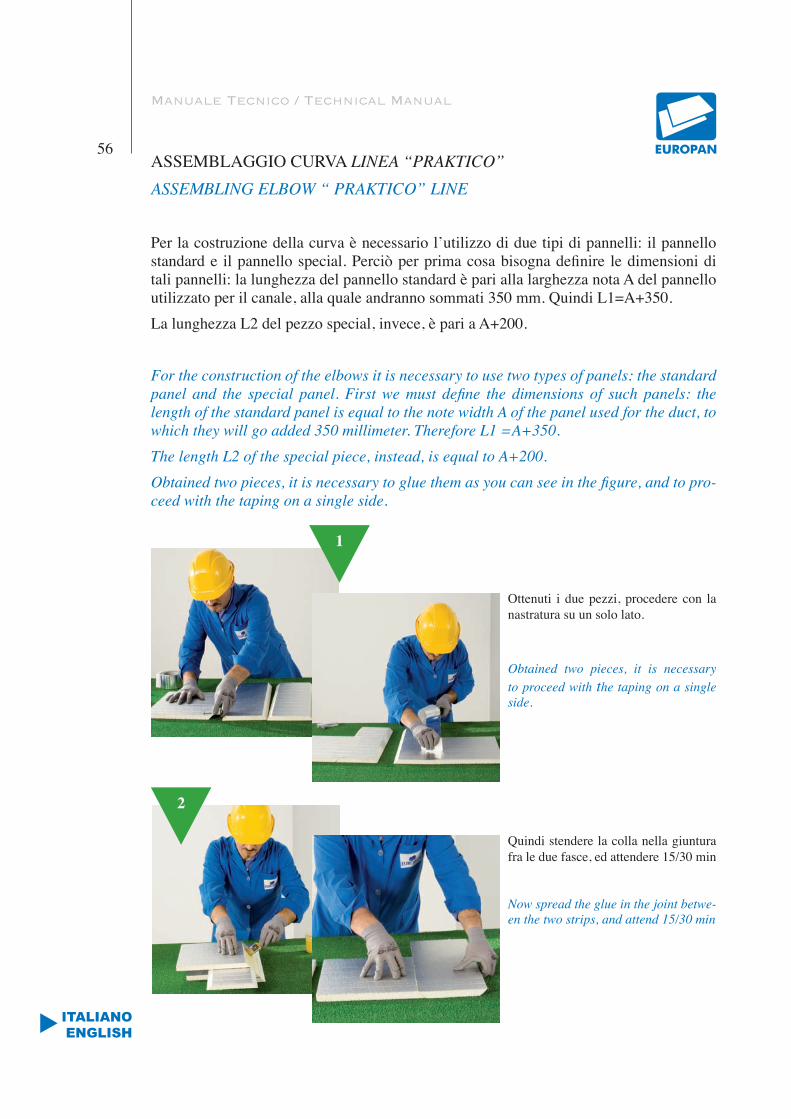
Manuale Tecnico / Technical Manual
56
ITALIANOENGLISH
ASSEMBLAGGIO CURVA LINEA “PRAKTICO”ASSEMBLING ELBOW “ PRAKTICO” LINE
Per la costruzione della curva è necessario l’utilizzo di due tipi di pannelli: il pannello standard e il pannello special. Perciò per prima cosa bisogna definire le dimensioni di tali pannelli: la lunghezza del pannello standard è pari alla larghezza nota A del pannello utilizzato per il canale, alla quale andranno sommati 350 mm. Quindi L1=A+350.La lunghezza L2 del pezzo special, invece, è pari a A+200.
For the construction of the elbows it is necessary to use two types of panels: the standard panel and the special panel. First we must define the dimensions of such panels: the length of the standard panel is equal to the note width A of the panel used for the duct, to which they will go added 350 millimeter. Therefore L1 =A+350.The length L2 of the special piece, instead, is equal to A+200.Obtained two pieces, it is necessary to glue them as you can see in the figure, and to pro-ceed with the taping on a single side.
Ottenuti i due pezzi, procedere con la nastratura su un solo lato.
Obtained two pieces, it is necessary to proceed with the taping on a single side.
Quindi stendere la colla nella giuntura fra le due fasce, ed attendere 15/30 min
Now spread the glue in the joint betwe-en the two strips, and attend 15/30 min
2
1

Manuale Tecnico / Technical Manual
57
ITALIANOENGLISH
3Procedere con l’incollaggio e la nastra-tura sull’altro lato.
Proceed with the taping on a single side.
4 Si traccia, poi, la curva, utilizzando l’apposita Dima: sul lato A del pannello special si sistema la Dima con l’aletta a 90° e si traccia il raggio interno della curva, facendo il calco della Dima.
The elbow can be traced, then using the appropriate Template: on the side A of the special panel using the Tem-plate with the fin to 90° trace the inner beam of the elbow, making the Templa-te’s cast.
5Il raggio esterno si traccia utilizzando un compasso a filo e/o un metro estensibile che abbia origine nel centro indicato sulla Dima, e ampiez-za compresa fra il centro e il bordo del pannello standard.Tracciata la curva, si procede al taglio mediante l’apposito taglierino comby, rispettando l’inclinazione del taglio della fascia standard.
Trace the external beam using a scribing compass and/or an exten-sible meter with origin in the center indicated on the Template, and amplitude comprised between the center and the edge of the standard panel.
Traced the elbow, proceed with the cut by an appropriate one comby cutter, respecting the inclination of the cut of the standard strip.
L’altro lato della curva si ottiene, uniti i pannelli standard e special, utilizzando la sagoma precedentemente tagliata
The other side of the elbow is obtained , once joined the standard and special panels, using the shape that was previously cut.
6

Manuale Tecnico / Technical Manual
58
ITALIANOENGLISH
Determinati i due lati curvi si procede all’incollaggio e successiva nastratura.
Determined two sides of the elbow, proceed to the sizing and successive taping.
7
8
Si termina con la fase di assemblaggio e chiusura del canale / Finish with the assembling phase and closure of the duct
9
La stesura del nastro avviene mediante l’utilizzo della spatola morbida.
Lay out of the tape is made by means of a soft spatula
10
Al pezzo del canale finito viene appli-cato uno strato di silicone per garantire una tenuta pneumatica.
In the interior angles of the finished piece of duct is applied a layer of si-licone to guarantee a pneumatic held.
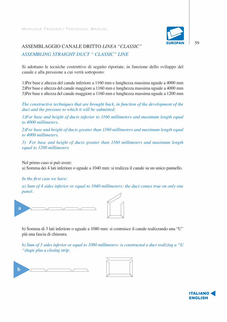
Manuale Tecnico / Technical Manual
59
ITALIANOENGLISH
ASSEMBLAGGIO CANALE DRITTO LINEA “CLASSIC”ASSEMBLING STRAIGHT DUCT “ CLASSIC” LINE
Si adottano le tecniche costruttive di seguito riportate, in funzione dello sviluppo del canale e alla pressione a cui verrà sottoposto:
1)Per base e altezza del canale inferiore a 1160 mm e lunghezza massima uguale a 4000 mm2)Per base e altezza del canale maggiore a 1160 mm e lunghezza massima uguale a 4000 mm3)Per base e altezza del canale maggiore a 1160 mm e lunghezza massima uguale a 1200 mm
The constructive techniques that are brought back, in function of the development of the duct and the pressure to which it will be submitted:1)For base and height of ducts inferior to 1160 millimeters and maximum length equal to 4000 millimeters.2)For base and height of ducts greater than 1160 millimeters and maximum length equal to 4000 millimeters.3) For base and height of ducts greater than 1160 millimeters and maximum length equal to 1200 millimeters
Nel primo caso si può avere:a) Somma dei 4 lati inferiore o uguale a 1040 mm: si realizza il canale su un unico pannello.
In the first case we have:a) Sum of 4 sides inferior or equal to 1040 millimeters: the duct comes true on only one panel.
b) Somma di 3 lati inferiore o uguale a 1080 mm: si costruisce il canale realizzando una “U” più una fascia di chiusura.
b) Sum of 3 sides inferior or equal to 1080 millimeters: is constructed a duct realizing a “U “shape plus a closing strip.
a
b
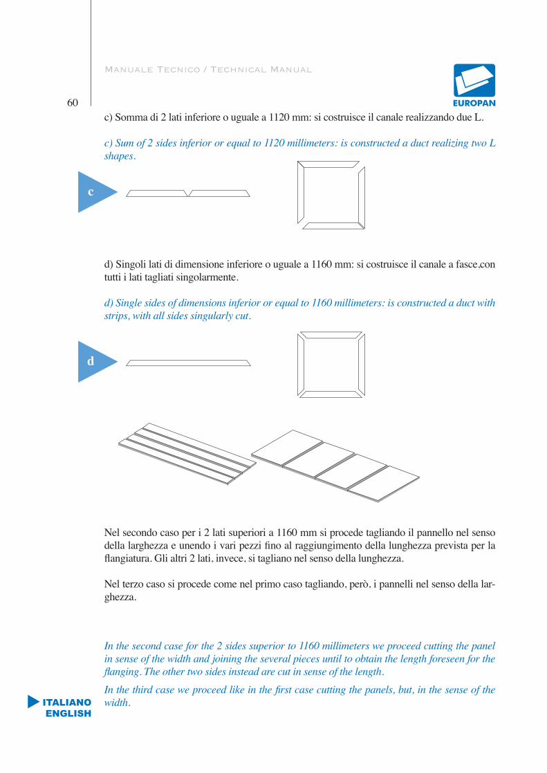
Manuale Tecnico / Technical Manual
60
ITALIANOENGLISH
c) Somma di 2 lati inferiore o uguale a 1120 mm: si costruisce il canale realizzando due L.
c) Sum of 2 sides inferior or equal to 1120 millimeters: is constructed a duct realizing two L shapes.
d) Singoli lati di dimensione inferiore o uguale a 1160 mm: si costruisce il canale a fasce,con tutti i lati tagliati singolarmente.
d) Single sides of dimensions inferior or equal to 1160 millimeters: is constructed a duct with strips, with all sides singularly cut.
Nel secondo caso per i 2 lati superiori a 1160 mm si procede tagliando il pannello nel senso della larghezza e unendo i vari pezzi fino al raggiungimento della lunghezza prevista per la flangiatura. Gli altri 2 lati, invece, si tagliano nel senso della lunghezza.
Nel terzo caso si procede come nel primo caso tagliando, però, i pannelli nel senso della lar-ghezza.
In the second case for the 2 sides superior to 1160 millimeters we proceed cutting the panel in sense of the width and joining the several pieces until to obtain the length foreseen for the flanging. The other two sides instead are cut in sense of the length.
In the third case we proceed like in the first case cutting the panels, but, in the sense of the width.
c
d
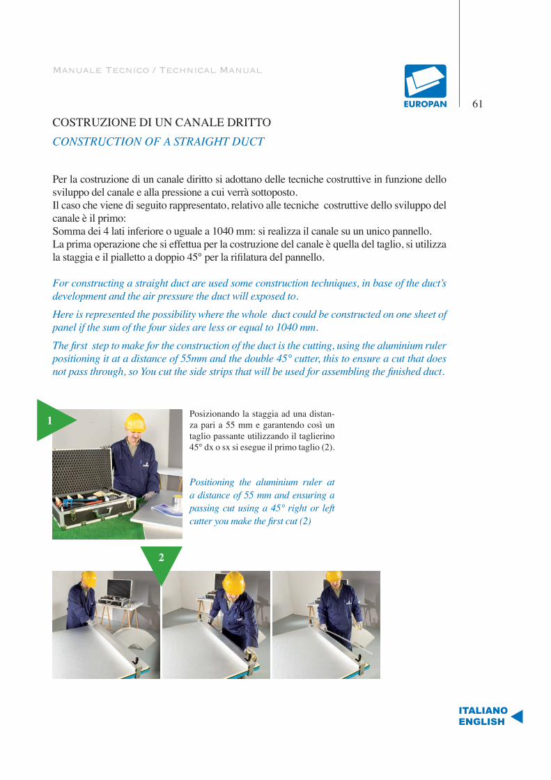
Manuale Tecnico / Technical Manual
61
ITALIANOENGLISH
COSTRUZIONE DI UN CANALE DRITTOCONSTRUCTION OF A STRAIGHT DUCT
Per la costruzione di un canale diritto si adottano delle tecniche costruttive in funzione dello sviluppo del canale e alla pressione a cui verrà sottoposto.Il caso che viene di seguito rappresentato, relativo alle tecniche costruttive dello sviluppo del canale è il primo:Somma dei 4 lati inferiore o uguale a 1040 mm: si realizza il canale su un unico pannello.La prima operazione che si effettua per la costruzione del canale è quella del taglio, si utilizza la staggia e il pialletto a doppio 45° per la rifilatura del pannello.
For constructing a straight duct are used some construction techniques, in base of the duct’s development and the air pressure the duct will exposed to.
Here is represented the possibility where the whole duct could be constructed on one sheet of panel if the sum of the four sides are less or equal to 1040 mm.
The first step to make for the construction of the duct is the cutting, using the aluminium ruler positioning it at a distance of 55mm and the double 45° cutter, this to ensure a cut that does not pass through, so You cut the side strips that will be used for assembling the finished duct.
1
2
Posizionando la staggia ad una distan-za pari a 55 mm e garantendo così un taglio passante utilizzando il taglierino 45° dx o sx si esegue il primo taglio (2).
Positioning the aluminium ruler at a distance of 55 mm and ensuring a passing cut using a 45° right or left cutter you make the first cut (2)

Manuale Tecnico / Technical Manual
62
ITALIANOENGLISH
3
Effettuato il primo taglio passante si procede a riposizionare la staggia ,ad un distanza pari alla dimensione del canale (b o h) alla quale si aggiungono 9 cm che corrispondono allo spessore del pialletto doppio 45° e si procede al taglio non passante.
Effected the first passing cut you proceed to re-position the aluminium ruler, at a distance equal to the dimension of the duct (b or h) at which You add 9 cm that correspond to the width of the double 45° cutter, so you proceed to the non passing cut.
Quindi si distribuisce la colla, in modo abbondante ed uniforme, su entrambi i tagli.La colla fa presa in circa 15/30 minuti.
Therefore the glue is distributed in abundant and uniform way, on both cuts. The glue grips in approximately 15/30 minutes.
4
Per una corretta chiusura del canale nel riposizionare la staggia bisogna alternare le misu-re b-h-b-h. Si procede alla chiusura del pezzo quando la colla non risulta più appiccicosa al tatto ripiegando le pareti del canale assicurandosi che la colla faccia presa pressando i pannelli accuratamente lungo tutta la lunghezza (4).
For a correct closure of the duct in re-positioning the aluminium ruler you must alternate the measures b-h-b-h. Therefore proceed to the closure of the piece when the glue does not turn out sticky to the touch, folding the walls of the duct pressing accurately the panels along all the length (4).
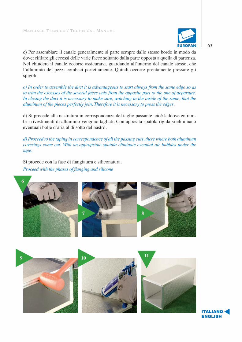
Manuale Tecnico / Technical Manual
63
ITALIANOENGLISH
c) Per assemblare il canale generalmente si parte sempre dallo stesso bordo in modo da dover rifilare gli eccessi delle varie facce soltanto dalla parte opposta a quella di partenza. Nel chiudere il canale occorre assicurarsi, guardando all’interno del canale stesso, che l’alluminio dei pezzi combaci perfettamente. Quindi occorre prontamente pressare gli spigoli.
c) In order to assemble the duct it is advantageous to start always from the same edge so as to trim the excesses of the several faces only from the opposite part to the one of departure. In closing the duct it is necessary to make sure, watching in the inside of the same, that the aluminum of the pieces perfectly join. Therefore it is necessary to press the edges.
d) Si procede alla nastratura in corrispondenza del taglio passante, cioè laddove entram-bi i rivestimenti di alluminio vengono tagliati. Con apposita spatola rigida si eliminano eventuali bolle d’aria al di sotto del nastro.
d) Proceed to the taping in correspondence of all the passing cuts, there where both aluminum coverings come cut. With an appropriate spatula eliminate eventual air bubbles under the tape.
Si procede con la fase di flangiatura e siliconatura.Proceed with the phases of flanging and silicone
7 8
6
109 11
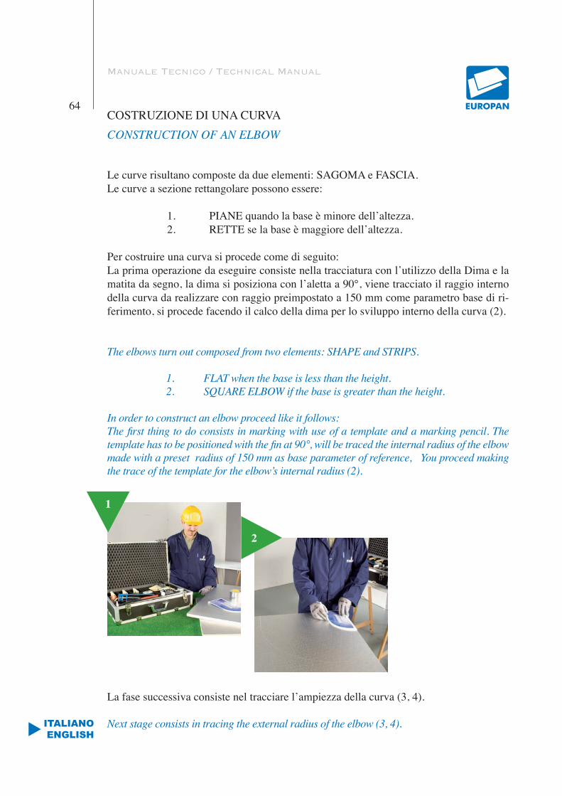
Manuale Tecnico / Technical Manual
64
ITALIANOENGLISH
COSTRUZIONE DI UNA CURVACONSTRUCTION OF AN ELBOW
Le curve risultano composte da due elementi: SAGOMA e FASCIA.Le curve a sezione rettangolare possono essere:
1. PIANE quando la base è minore dell’altezza.2. RETTE se la base è maggiore dell’altezza.
Per costruire una curva si procede come di seguito:La prima operazione da eseguire consiste nella tracciatura con l’utilizzo della Dima e la matita da segno, la dima si posiziona con l’aletta a 90°, viene tracciato il raggio interno della curva da realizzare con raggio preimpostato a 150 mm come parametro base di ri-ferimento, si procede facendo il calco della dima per lo sviluppo interno della curva (2).
The elbows turn out composed from two elements: SHAPE and STRIPS.
1. FLAT when the base is less than the height.2. SQUARE ELBOW if the base is greater than the height.
In order to construct an elbow proceed like it follows:The first thing to do consists in marking with use of a template and a marking pencil. The template has to be positioned with the fin at 90°, will be traced the internal radius of the elbow made with a preset radius of 150 mm as base parameter of reference, You proceed making the trace of the template for the elbow’s internal radius (2).
La fase successiva consiste nel tracciare l’ampiezza della curva (3, 4).
Next stage consists in tracing the external radius of the elbow (3, 4).
1
2
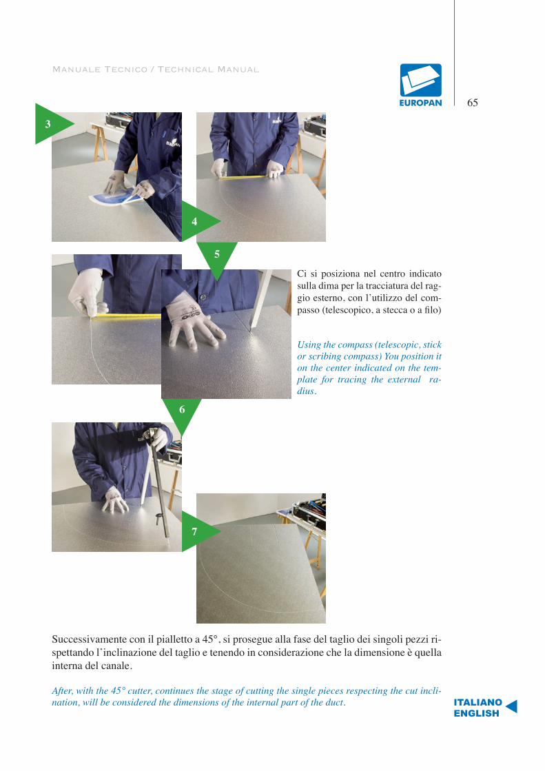
Manuale Tecnico / Technical Manual
65
ITALIANOENGLISH
3
4
Ci si posiziona nel centro indicato sulla dima per la tracciatura del rag-gio esterno, con l’utilizzo del com-passo (telescopico, a stecca o a filo)
Using the compass (telescopic, stick or scribing compass) You position it on the center indicated on the tem-plate for tracing the external ra-dius.
6
7
5
Successivamente con il pialletto a 45°, si prosegue alla fase del taglio dei singoli pezzi ri-spettando l’inclinazione del taglio e tenendo in considerazione che la dimensione è quella interna del canale.
After, with the 45° cutter, continues the stage of cutting the single pieces respecting the cut incli-nation, will be considered the dimensions of the internal part of the duct.
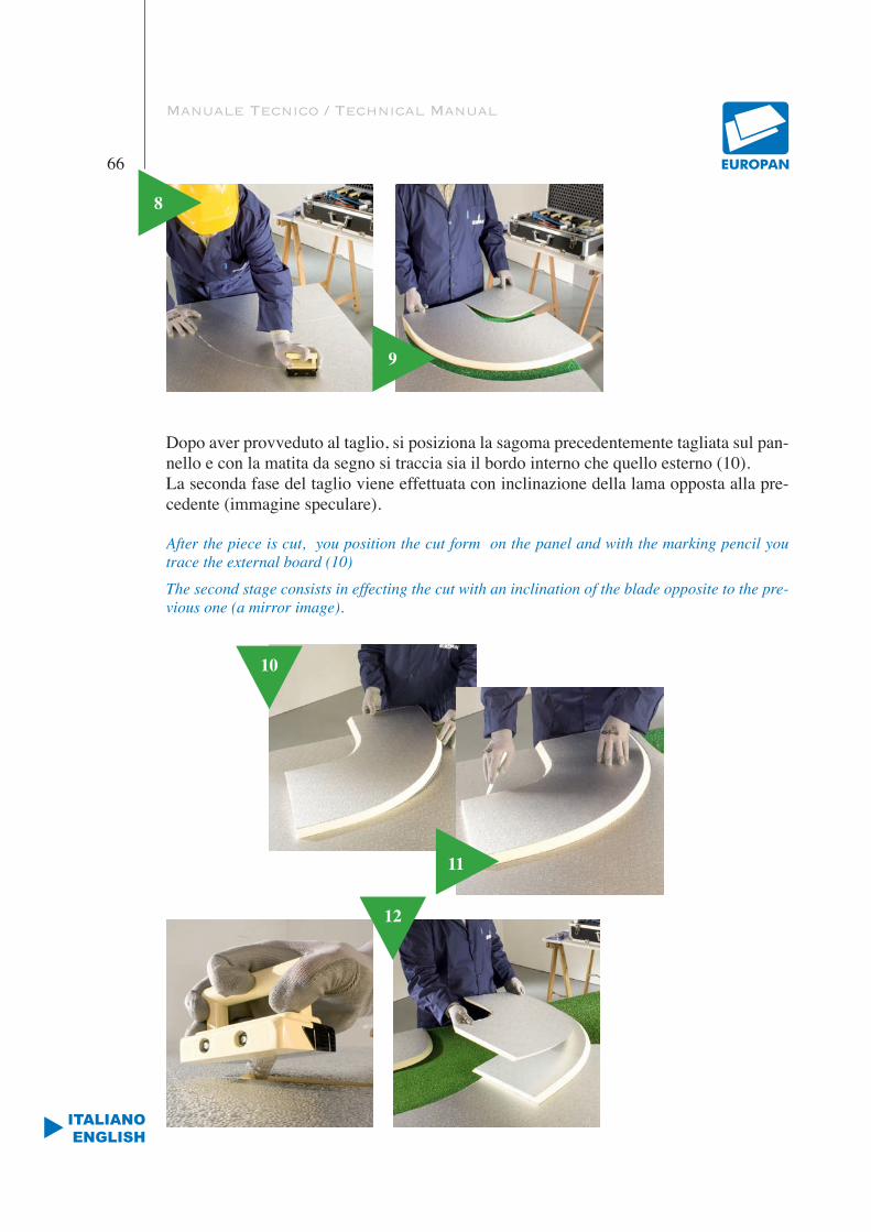
Manuale Tecnico / Technical Manual
66
ITALIANOENGLISH
8
9
Dopo aver provveduto al taglio, si posiziona la sagoma precedentemente tagliata sul pan-nello e con la matita da segno si traccia sia il bordo interno che quello esterno (10).La seconda fase del taglio viene effettuata con inclinazione della lama opposta alla pre-cedente (immagine speculare).
After the piece is cut, you position the cut form on the panel and with the marking pencil you trace the external board (10)
The second stage consists in effecting the cut with an inclination of the blade opposite to the pre-vious one (a mirror image).
11
12
10
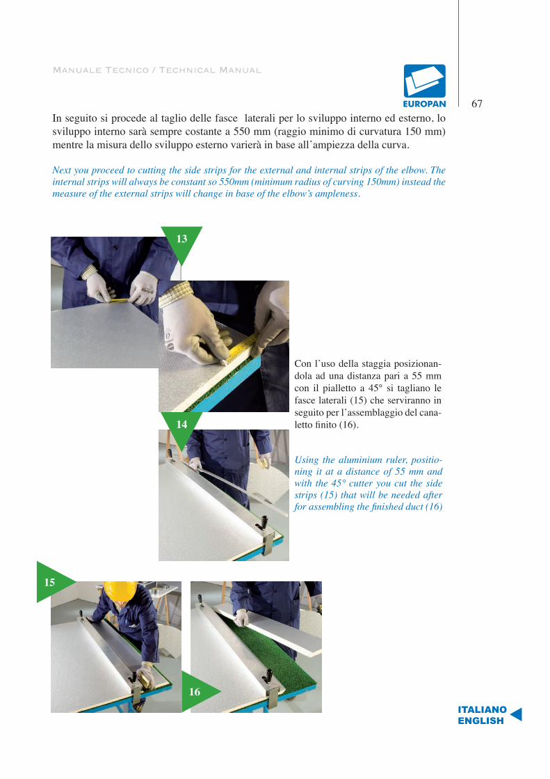
Manuale Tecnico / Technical Manual
67
ITALIANOENGLISH
In seguito si procede al taglio delle fasce laterali per lo sviluppo interno ed esterno, lo sviluppo interno sarà sempre costante a 550 mm (raggio minimo di curvatura 150 mm) mentre la misura dello sviluppo esterno varierà in base all’ampiezza della curva.
Next you proceed to cutting the side strips for the external and internal strips of the elbow. The internal strips will always be constant so 550mm (minimum radius of curving 150mm) instead the measure of the external strips will change in base of the elbow’s ampleness.
Con l’uso della staggia posizionan-dola ad una distanza pari a 55 mm con il pialletto a 45° si tagliano le fasce laterali (15) che serviranno in seguito per l’assemblaggio del cana-letto finito (16).
Using the aluminium ruler, positio-ning it at a distance of 55 mm and with the 45° cutter you cut the side strips (15) that will be needed after for assembling the finished duct (16)
13
14
15
16
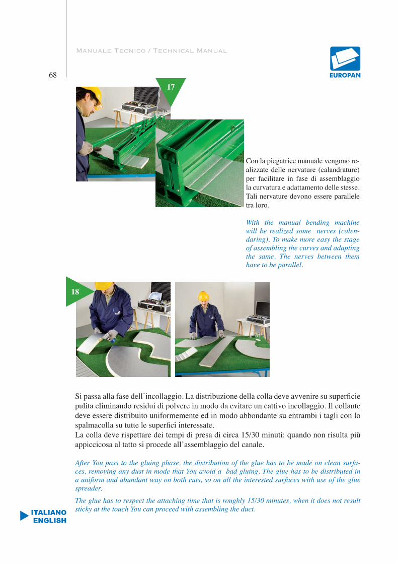
Manuale Tecnico / Technical Manual
68
ITALIANOENGLISH
Con la piegatrice manuale vengono re-alizzate delle nervature (calandrature) per facilitare in fase di assemblaggio la curvatura e adattamento delle stesse. Tali nervature devono essere parallele tra loro.
With the manual bending machine will be realized some nerves (calen-daring). To make more easy the stage of assembling the curves and adapting the same. The nerves between them have to be parallel.
17
18
Si passa alla fase dell’incollaggio. La distribuzione della colla deve avvenire su superficie pulita eliminando residui di polvere in modo da evitare un cattivo incollaggio. Il collante deve essere distribuito uniformemente ed in modo abbondante su entrambi i tagli con lo spalmacolla su tutte le superfici interessate.La colla deve rispettare dei tempi di presa di circa 15/30 minuti: quando non risulta più appiccicosa al tatto si procede all’assemblaggio del canale.
After You pass to the gluing phase, the distribution of the glue has to be made on clean surfa-ces, removing any dust in mode that You avoid a bad gluing. The glue has to be distributed in a uniform and abundant way on both cuts, so on all the interested surfaces with use of the glue spreader.
The glue has to respect the attaching time that is roughly 15/30 minutes, when it does not result sticky at the touch You can proceed with assembling the duct.

Manuale Tecnico / Technical Manual
69
ITALIANOENGLISH
18 Si procede alla nastratura in corrispondenza di tutti tagli passanti cioè laddove en-trambi i rivestimenti di allu-minio vengono tagliati.
Proceed with the taping in correspondence of all the passing cuts, there where all the aluminium coatings are cut.
19
L’operazione viene completata con una successiva stesura del nastro mediante la spatola morbida in modo tale da evi-tare la formazione di bolle d’aria al di sotto del nastro.
The next step consists in passing on the aluminium tape with a soft spatula in mode to avoid air bubbles underneath the tape.
20La fase di assemblaggio e chiusura del canale consiste nell’unio-ne dei pannelli facendo ruotare le sagome contemporaneamente lungo il bordo della fascia esterna tenendo conto di far corri-spondere gli angoli interni, alluminio con alluminio, lo sviluppo interno della curva verrà assemblato per ultimo (22).
The assembling phase and closing of the duct consists in joi-ning the panels, rotating the shapes at the same time along the boards of the external strips making the internal angles match, aluminium with aluminium. At last will be assembled the inter-nal strip of the elbow (22).
21
22

Manuale Tecnico / Technical Manual
70
ITALIANOENGLISH
23
L’operazione di chiusura del canale viene completata con la pressatura de-gli angoli utilizzando la spatola rigida (23) e l’operazione di nastratura uti-lizzando il segna nastro (24) e la spa-tola morbida (25).
The phase of closing the duct will be completed with pressing the angles using the rigid spatula (23) with the tape marker (24) and the soft spatula (25).
24
26
25
La rifinitura del tronco di canale si completa con l’applicazione di profili in tutte le bocche dei pezzi e agli spigoli si utilizzano le squa-drette zincate per garantire una rigidità al canale. I profili sono in lega di alluminio e vengono ap-plicati con l’ausilio di colle spe-cifiche. Occorre assicurarsi che i bordi terminali dei pezzi siano ben rifilati.
27
The finishing of the duct is completed by applying profiles in all mouths of the pieces using in the edges the zinc-coated angles that guarantee more rigidity to the duct. The profiles are in alloy aluminium, they have to be applied using specific glues. Assure that the terminal boards of the profiles are well trimmed.
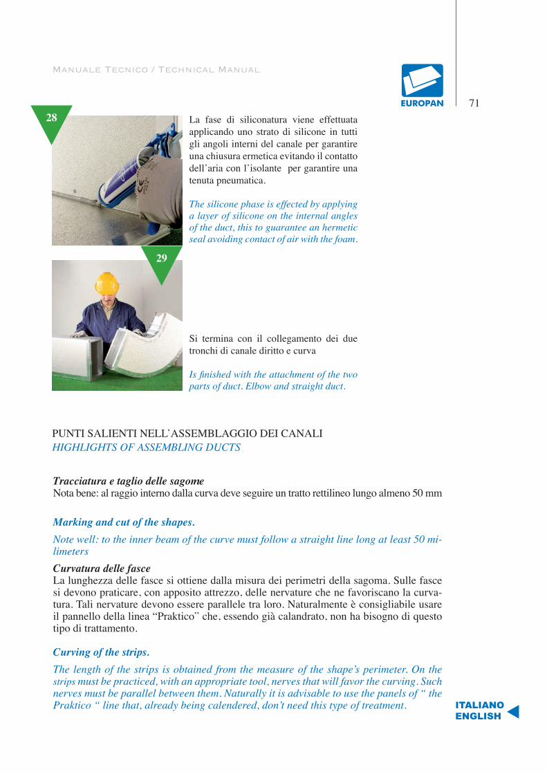
Manuale Tecnico / Technical Manual
71
ITALIANOENGLISH
28 La fase di siliconatura viene effettuata applicando uno strato di silicone in tutti gli angoli interni del canale per garantire una chiusura ermetica evitando il contatto dell’aria con l’isolante per garantire una tenuta pneumatica.
The silicone phase is effected by applying a layer of silicone on the internal angles of the duct, this to guarantee an hermetic seal avoiding contact of air with the foam.
Si termina con il collegamento dei due tronchi di canale diritto e curva
Is finished with the attachment of the two parts of duct. Elbow and straight duct.
29
Tracciatura e taglio delle sagomeNota bene: al raggio interno dalla curva deve seguire un tratto rettilineo lungo almeno 50 mm
Marking and cut of the shapes.Note well: to the inner beam of the curve must follow a straight line long at least 50 mi-limetersCurvatura delle fasceLa lunghezza delle fasce si ottiene dalla misura dei perimetri della sagoma. Sulle fasce si devono praticare, con apposito attrezzo, delle nervature che ne favoriscano la curva-tura. Tali nervature devono essere parallele tra loro. Naturalmente è consigliabile usare il pannello della linea “Praktico” che, essendo già calandrato, non ha bisogno di questo tipo di trattamento.
Curving of the strips. The length of the strips is obtained from the measure of the shape’s perimeter. On the strips must be practiced, with an appropriate tool, nerves that will favor the curving. Such nerves must be parallel between them. Naturally it is advisable to use the panels of “ the Praktico “ line that, already being calendered, don’t need this type of treatment.
PUNTI SALIENTI NELL’ASSEMBLAGGIO DEI CANALIHIGHLIGHTS OF ASSEMBLING DUCTS

Manuale Tecnico / Technical Manual
72
ITALIANOENGLISH
IncollaggioSi verifica che le superfici siano prive di polvere e si provvede eventualmente alla puli-zia spazzolandole. Quindi si distribuisce la colla, in modo abbondante ed uniforme, su entrambi i tagli. La colla fa presa in circa 15/30 minuti. Quando la colla non risulta più appiccicosa al tatto si procede alla chiusura del pezzo.
GluingVerify that the superficial cuts are lacking in powder and eventually provide to clean them by brushing them. Therefore the glue is distributed, in abundant and uniform way, on both cuts. The glue grips in approximately 15/30 minutes. When the glue does not turn out sti-cky to the touch proceed to the closure of the piece.
AssemblaggioPer l’assemblaggio si fanno ruotare le sagome contemporaneamente lungo il bordo della fascia esterna. La fascia interna va assemblata per ultima.
AssemblingFor the assembling the shapes you have to ruotate at the same time along the external edge of the external strip. The internal strip is assembled for last.
NastraturaSi procede alla nastratura in corrispondenza di tutti i tagli passanti, cioè laddove entrambi i rivestimenti di alluminio vengono tagliati. Quindi, con apposita spatola si eliminano eventuali bolle d’aria al di sotto del nastro.
TapingProceed to the taping in correspondence of all the passing cuts, there where both alumi-num coverings come cut. Therefore, with an appropriate spatula eliminate eventual air bubbles under the tape.
Applicazione profili. In tutte le bocche dei pezzi vengono applicati i profilati, a seconda di ciò che va unito. I profili sono in lega di alluminio o in PVC. Naturalmente, prima di applicare i profili, occorre assicurarsi che i bordi terminali dei pezzi siano ben rifilati.Poiché i pannelli possono essere uniti fra loro, le curve possono essere costruite anche unendo un ritaglio a una fascia di pannello.
Profiles applicationIn all the mouths of the pieces are second of what goes joined. The profiles they are in aluminum alloy or in PVC. Naturally, before applying the profiles, it is necessary to make sure that the edges are perfectly trimmed.So the panels can be joined between themselves, the elbows can be constructed also joi-ning a remaining strip of panel.
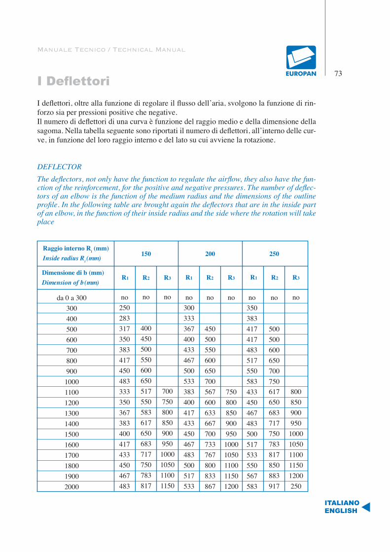
Manuale Tecnico / Technical Manual
I Deflettori73
ITALIANOENGLISH
I deflettori, oltre alla funzione di regolare il flusso dell’aria, svolgono la funzione di rin-forzo sia per pressioni positive che negative.Il numero di deflettori di una curva è funzione del raggio medio e della dimensione della sagoma. Nella tabella seguente sono riportati il numero di deflettori, all’interno delle cur-ve, in funzione del loro raggio interno e del lato su cui avviene la rotazione.
DEFLECTORThe deflectors, not only have the function to regulate the airflow, they also have the fun-ction of the reinforcement, for the positive and negative pressures. The number of deflec-tors of an elbow is the function of the medium radius and the dimensions of the outline profile. In the following table are brought again the deflectors that are in the inside part of an elbow, in the function of their inside radius and the side where the rotation will take place
Raggio interno Ri (mm)Inside radius Ri (mm)
da 0 a 30030040050060070080090010001100120013001400150016001700180019002000
Dimensione di b (mm)Dimension of b (mm)
150 200 250
R1 R2 R3 R1 R2 R3 R1 R2 R3
no250283317350383417450483333350367383400417433450467483
no
400450500550600650517550583617650683717750783817
no300333367400433467500533383400417433450467483500517533
no
450500550600650700567600633667700733767800833867
no
75080085090095010001050110011501200
no350383417417483517550583433450467483500517533550567583
no
500500600650700750617650683717750783817850883917
no
80085090095010001050110011501200250
no
7007508008509009501000105011001150
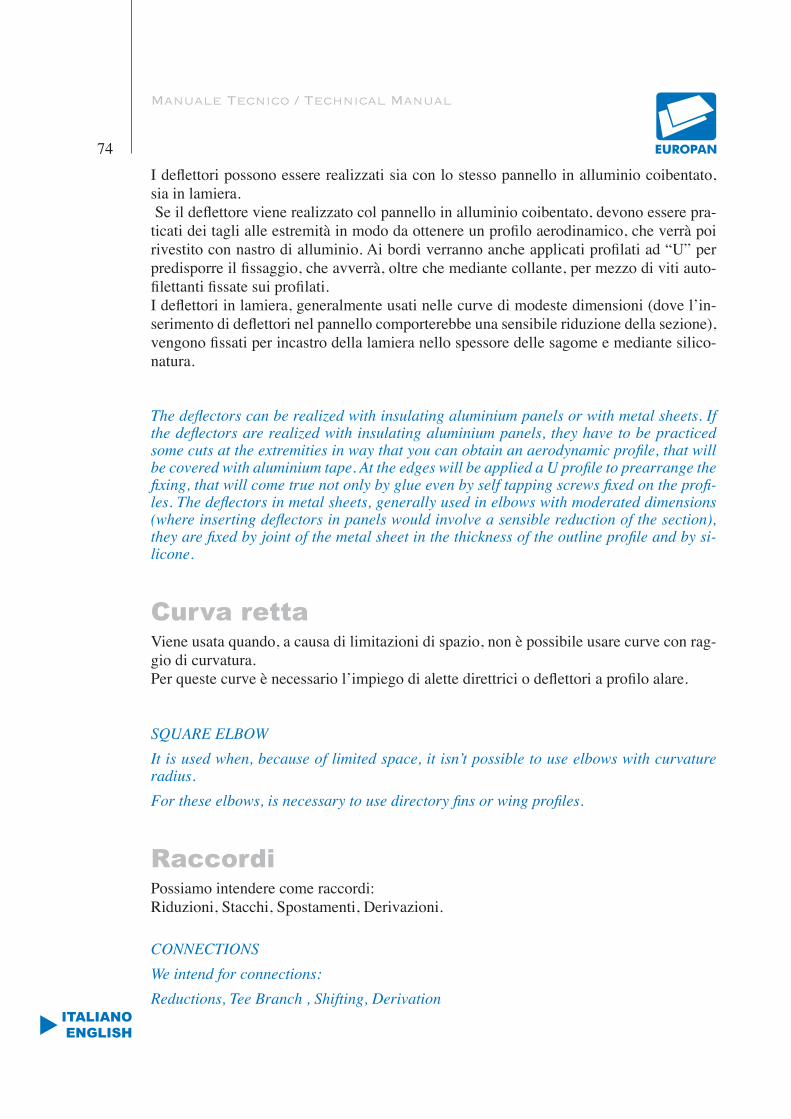
Manuale Tecnico / Technical Manual
74
ITALIANOENGLISH
I deflettori possono essere realizzati sia con lo stesso pannello in alluminio coibentato, sia in lamiera. Se il deflettore viene realizzato col pannello in alluminio coibentato, devono essere pra-ticati dei tagli alle estremità in modo da ottenere un profilo aerodinamico, che verrà poi rivestito con nastro di alluminio. Ai bordi verranno anche applicati profilati ad “U” per predisporre il fissaggio, che avverrà, oltre che mediante collante, per mezzo di viti auto-filettanti fissate sui profilati.I deflettori in lamiera, generalmente usati nelle curve di modeste dimensioni (dove l’in-serimento di deflettori nel pannello comporterebbe una sensibile riduzione della sezione), vengono fissati per incastro della lamiera nello spessore delle sagome e mediante silico-natura.
The deflectors can be realized with insulating aluminium panels or with metal sheets. If the deflectors are realized with insulating aluminium panels, they have to be practiced some cuts at the extremities in way that you can obtain an aerodynamic profile, that will be covered with aluminium tape. At the edges will be applied a U profile to prearrange the fixing, that will come true not only by glue even by self tapping screws fixed on the profi-les. The deflectors in metal sheets, generally used in elbows with moderated dimensions (where inserting deflectors in panels would involve a sensible reduction of the section), they are fixed by joint of the metal sheet in the thickness of the outline profile and by si-licone.
Curva rettaViene usata quando, a causa di limitazioni di spazio, non è possibile usare curve con rag-gio di curvatura.Per queste curve è necessario l’impiego di alette direttrici o deflettori a profilo alare.
SQUARE ELBOWIt is used when, because of limited space, it isn’t possible to use elbows with curvature radius.For these elbows, is necessary to use directory fins or wing profiles.
RaccordiPossiamo intendere come raccordi:Riduzioni, Stacchi, Spostamenti, Derivazioni.
CONNECTIONSWe intend for connections:Reductions, Tee Branch , Shifting, Derivation
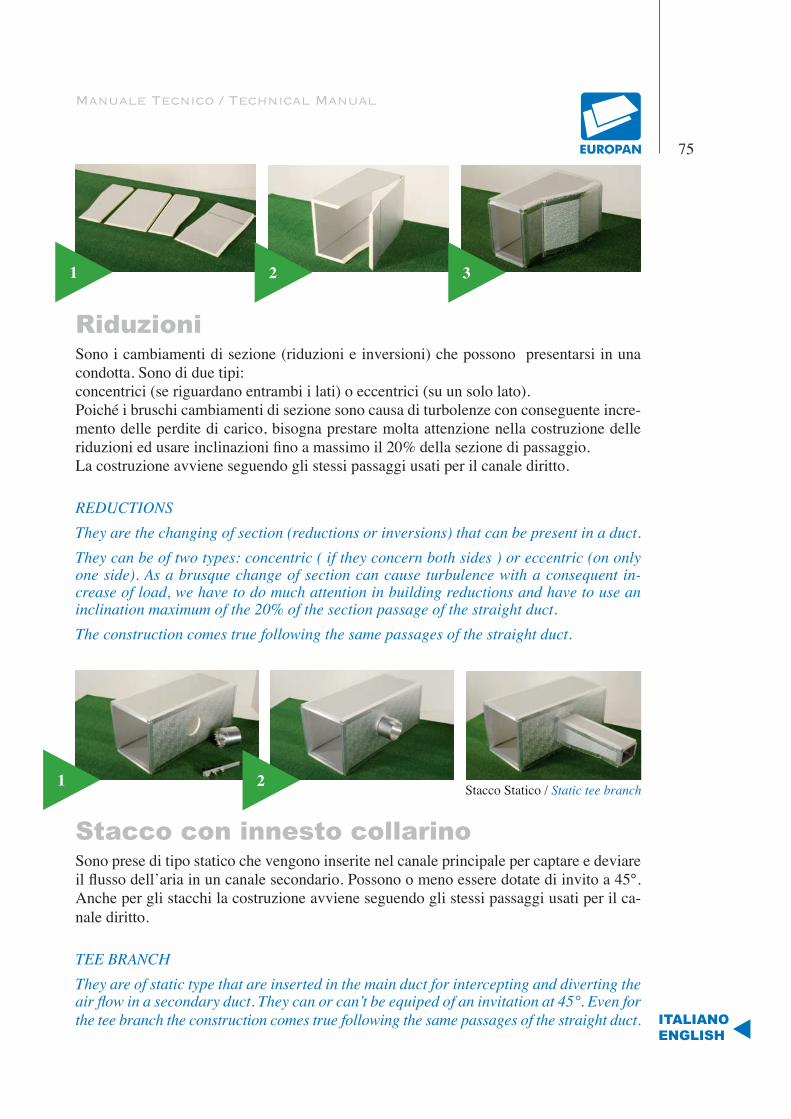
Manuale Tecnico / Technical Manual
75
ITALIANOENGLISH
RiduzioniSono i cambiamenti di sezione (riduzioni e inversioni) che possono presentarsi in una condotta. Sono di due tipi:concentrici (se riguardano entrambi i lati) o eccentrici (su un solo lato).Poiché i bruschi cambiamenti di sezione sono causa di turbolenze con conseguente incre-mento delle perdite di carico, bisogna prestare molta attenzione nella costruzione delle riduzioni ed usare inclinazioni fino a massimo il 20% della sezione di passaggio.La costruzione avviene seguendo gli stessi passaggi usati per il canale diritto.
REDUCTIONSThey are the changing of section (reductions or inversions) that can be present in a duct.They can be of two types: concentric ( if they concern both sides ) or eccentric (on only one side). As a brusque change of section can cause turbulence with a consequent in-crease of load, we have to do much attention in building reductions and have to use an inclination maximum of the 20% of the section passage of the straight duct.The construction comes true following the same passages of the straight duct.
Stacco con innesto collarinoSono prese di tipo statico che vengono inserite nel canale principale per captare e deviare il flusso dell’aria in un canale secondario. Possono o meno essere dotate di invito a 45°. Anche per gli stacchi la costruzione avviene seguendo gli stessi passaggi usati per il ca-nale diritto.
TEE BRANCHThey are of static type that are inserted in the main duct for intercepting and diverting the air flow in a secondary duct. They can or can’t be equiped of an invitation at 45°. Even for the tee branch the construction comes true following the same passages of the straight duct.
1 2 3
1 2 Stacco Statico / Static tee branch
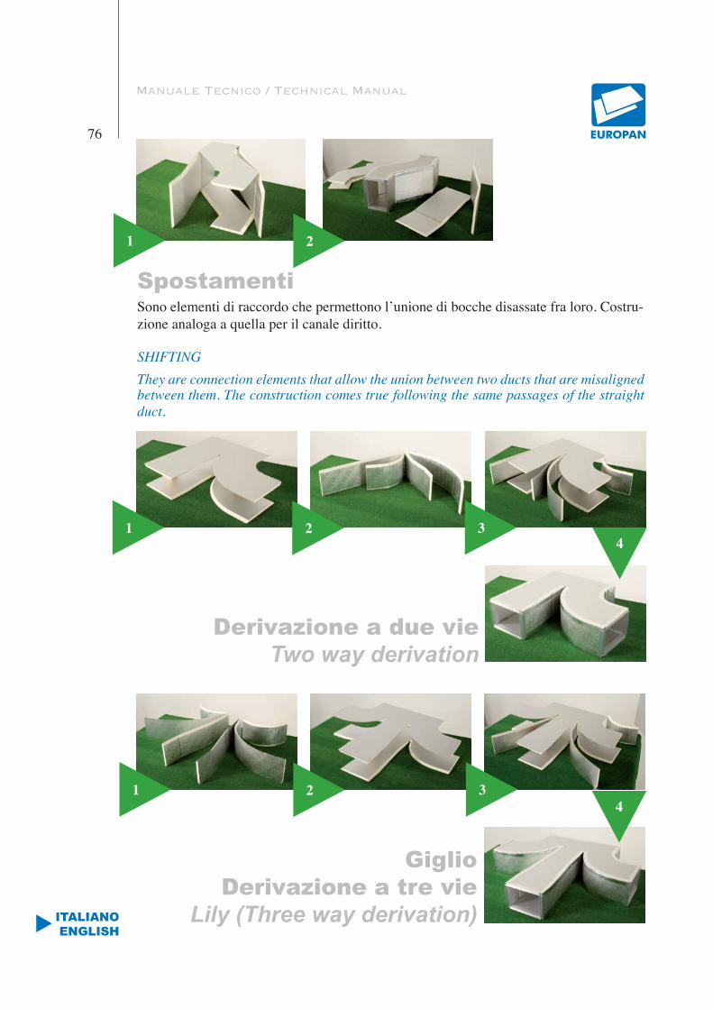
Manuale Tecnico / Technical Manual
76
ITALIANOENGLISH
SpostamentiSono elementi di raccordo che permettono l’unione di bocche disassate fra loro. Costru-zione analoga a quella per il canale diritto.
SHIFTINGThey are connection elements that allow the union between two ducts that are misaligned between them. The construction comes true following the same passages of the straight duct.
1 2
1 2 3
1 2 3
4
4
Derivazione a due vieTwo way derivation
GiglioDerivazione a tre vie
Lily (Three way derivation)
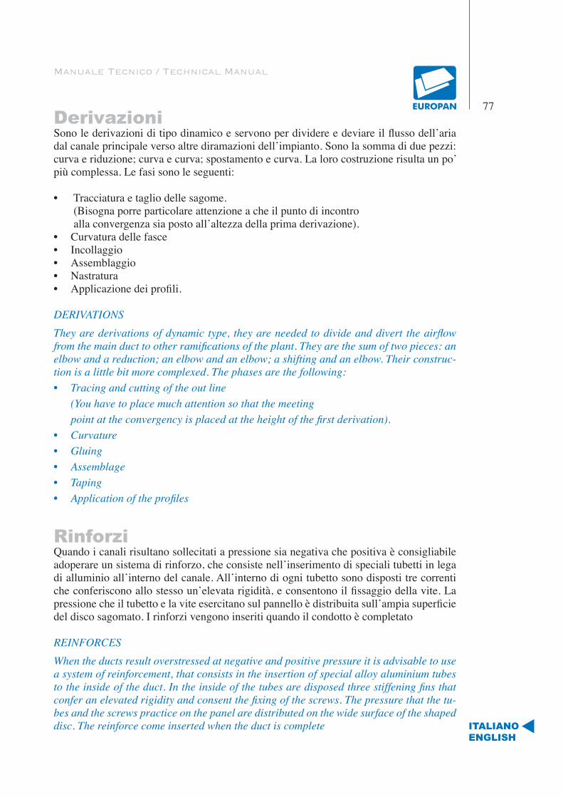
Manuale Tecnico / Technical Manual
77
ITALIANOENGLISH
DerivazioniSono le derivazioni di tipo dinamico e servono per dividere e deviare il flusso dell’aria dal canale principale verso altre diramazioni dell’impianto. Sono la somma di due pezzi: curva e riduzione; curva e curva; spostamento e curva. La loro costruzione risulta un po’ più complessa. Le fasi sono le seguenti:
• Tracciatura e taglio delle sagome. (Bisogna porre particolare attenzione a che il punto di incontro alla convergenza sia posto all’altezza della prima derivazione).• Curvatura delle fasce• Incollaggio• Assemblaggio• Nastratura• Applicazione dei profili.
DERIVATIONSThey are derivations of dynamic type, they are needed to divide and divert the airflow from the main duct to other ramifications of the plant. They are the sum of two pieces: an elbow and a reduction; an elbow and an elbow; a shifting and an elbow. Their construc-tion is a little bit more complexed. The phases are the following:• Tracing and cutting of the out line (You have to place much attention so that the meeting point at the convergency is placed at the height of the first derivation).• Curvature• Gluing• Assemblage• Taping• Application of the profiles
Rinforzi Quando i canali risultano sollecitati a pressione sia negativa che positiva è consigliabile adoperare un sistema di rinforzo, che consiste nell’inserimento di speciali tubetti in lega di alluminio all’interno del canale. All’interno di ogni tubetto sono disposti tre correnti che conferiscono allo stesso un’elevata rigidità, e consentono il fissaggio della vite. La pressione che il tubetto e la vite esercitano sul pannello è distribuita sull’ampia superficie del disco sagomato. I rinforzi vengono inseriti quando il condotto è completato
REINFORCESWhen the ducts result overstressed at negative and positive pressure it is advisable to use a system of reinforcement, that consists in the insertion of special alloy aluminium tubes to the inside of the duct. In the inside of the tubes are disposed three stiffening fins that confer an elevated rigidity and consent the fixing of the screws. The pressure that the tu-bes and the screws practice on the panel are distributed on the wide surface of the shaped disc. The reinforce come inserted when the duct is complete
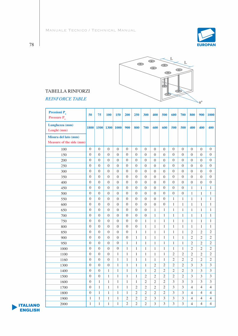
Manuale Tecnico / Technical Manual
78
ITALIANOENGLISH
Pressioni Pa
Pressure Pa
100150200250300350400450500550600650700750800850900950
10001100116013001400150016001700180019002000
Lunghezza (mm)Lenght (mm)
1800 1500 1300 1000 900 800 700 600 600 500 500 400 400 400
50 75 100 150 200 250 300 400 500 600 700 800 900 1000
00000000000000000000000000011
00000000000000000000000011111
00000000000000000000001111111
00000000000000000001111111111
00000000000000000111111111122
00000000000000011111111112222
00000000000001111111111222222
00000000000111111111122222233
00000000000111111111122222233
00000000011111111112222233333
00000000011111111112222233333
00000001111111122222233334444
00000001111111122222233334444
00000001111111122222233334444
Misura del lato (mm)Measure of the side (mm)
TABELLA RINFORZI REINFORCE TABLE
LL
n°

Manuale Tecnico / Technical Manual
79
ITALIANOENGLISH
FlangiaturaFLANGING
1
5
2
6
3
7
4
8

3
Manuale Tecnico / Technical Manual
80
ITALIANOENGLISH
Giunto antivibranteANTIVIBRATION JOINT
1
4
5
6
8
2

Manuale Tecnico / Technical Manual
81
ITALIANOENGLISH
Sistema condottoAIR DUCT SYSTEM
FLANGIA A SCOMPARSA.Profilo in alluminio da utilizzare unitamente alla baionetta ad H in pvc per l’unione delle condotte. Garantisce un’ottima tenuta pneu-matica.INVISIBLE FLANGE.Natural aluminium profile to use together with the PVC “H” bayonet made to join ducts. It guarantees an excellent pneumatic seal.
SQUADRETTA DI RINFORZO Squadretta in acciaio zincato da inserire sot-to le flange di collegamento agli angoli delle condotte. Assicura la perfetta messa in squa-dra del condotto.REINFORCEMENT ANGLE.Zinc coated angle to insert under the flanges of connection to the angles of the ducts. As-sures the perfect setting in square o fthe duct.
COLLA SPECIAL Colla specifica per ottenere un’ottima adesio-ne. Da utilizzare per incollaggio dei pannelli. Prima di unire le superfici trattate è necessario attendere per 15-20 minuti.SPECIAL GLUE.Specific glue to obtain the best adhesion. To use for the gluing of the panels. To get best adhesion it is necessary to wait about 15-20 minutes after spreading the glue on to surfaces with a simple paintbrush.
NASTRO IN ALLUMINIODa utilizzare per l’unione longitudinali tra pannelli.ALUMINIUM TAPETo use for the longitudinal union among pa-nels.
COLLA FASTColla poliuretanica per l’incollaggio dei profili in alluminio.FAST GLUE.Polyurethane glue, useful for sticking together aluminium profiles.
ANGOLARE DI COPERTURAAngolare per la finitura estetica dell’angolo di giunzione della flangia a scomparsa.COVERING ANGLE.Covering angle, made to improve the external appearance of the joint angles of the invisible flange.
BAIONETTA “H” IN PVCProfilo in PVC da utilizzare per l’unione tra flange a scomparsa o con flange per stacchi. Garantisce un’ottima tenuta pneumatica.PVC “H” BAYONET.PVC profile to use for the union among in-visible flanges or with tee branch flanges. It guarantees an excellent pneumatic seal.
SIGILLANTE SIL. KSigillante siliconico con ottime caratteristiche di adesione e resistenza all’invecchiamento. Assicura la tenuta pneumatica lungo tutto il condotto. Da applicare all’interno del condot-to, lungo l’angolo di ’unione tra i pannelli.SIL K. SEALING.Sealing silicone presenting good adhesion and ageing resistance characteristic. It guarantees a pneumatic seal in all the duct. To apply in the duct, in the union among panels.
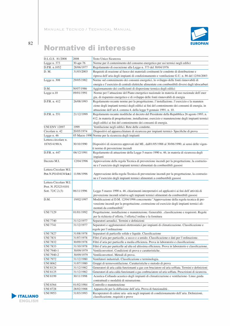
Manuale Tecnico / Technical Manual
Normative di interesse82
ITALIANOENGLISH
D.L.G.S. 81/2008 2008 Testo Unico Sicurezza Legge n. 373 30-apr-76 Norme per il contenimento del consumo energetico per usi termici negli edificiD.P.R. n.1052 28/06/1977 Regolamento di esecuzione alla Legge n. 373 del 30/04/1976D. M. 31/03/2003 Requisiti di reazione al fuoco dei materiali costituenti le condotte di distribuzione e ripresa dell’aria degli impianti di condizionamento e ventilazione G.U. n. 86 del 12/04/2003Legge n. 308 29/05/1982 Norme sul contenimento dei consumi energetici, lo sviluppo delle fonti rinnovabili di energia e l’esercizio di centrali elettriche alimentate con combustibili diversi dagli idrocarburiD.M. 30/07/1986 Aggiornamento dei coefficienti di dispersione termica degli edificiLegge n.10 09/01/1991 Norme per l’attuazione del Piano energetico nazionale in materia di uso razionale dell’ener gia, di risparmio energetico e di sviluppo delle fonti rinnovabili di energiaD.P.R. n. 412 26/08/1993 Regolamento recante norme per la progettazione, l’installazione, l’esercizio e la manuten zione degli impianti termici degli edifici ai fini del contenimento dei consumi di energia, in attuazione dell’art.4, comma 4, della legge 9 gennaio 1991, n. 10.D.P.R. n. 551 21/12/1999 Regolamento recante modifiche al decreto del Presidente della Repubblica 26 agosto 1993, n. 412, in materia di progettazione, installazione, esercizio e manutenzione degli impianti termici degli edifici ai fini del contenimento dei consumi di energia.UNI ENV 12097 1999 Ventilazione negli edifici. Rete delle condotte.Circolare n. 42 20/05/1974 Dispositivi ed apparecchiature di sicurezza per impianti termici- Specifiche di provaLegge n. 46 05 Marzo 1990 Norme per la sicurezza degli impiantiLettera circolare n.18765/4190/A 30/10/1990 Dispositivi di sicurezza approvati dal MI., dal01/05/1988 al 30/06/1990, ai sensi delle vigen- ti norme di prevenzione incendiD.P.R. n. 447 06/12/1991 Regolamento di attuazione della Legge 5 marzo 1990 n. 46, in materia di sicurezza degli impiantiDecreto M.I. 12/04/1996 Approvazione della regola Tecnica di prevenzione incendi per la progettazione, la costruzio- ne e l’esercizio degli impianti termici alimentati da combustibili gassosiLettera Circolare M.I.Prot. N. P1143/4134 Sott.1 11/06/1996 Approvazione della regola Tecnica di prevenzione incendi per la progettazione, la costruzio- ne e l’esercizio degli impianti termici alimentati a combustibili gassosiLettera Circolare M.I.Prot. N. P2323/4101Sott. 72/C.2.(3) 06/11/1996 Legge 5 marzo 1990 n. 46, chiarimenti interpretativi ed applicativi ai fini dell’attività di prevenzione incendi relativa agli impianti termici alimentati da combustibili gassosiD.M. 19/02/1997 Modificazioni al D.M. 12/04/1996 concernente:”Approvazione della regola tecnica di pre- venzione incendi per la progettazione, costruzione ed esercizio degli impianti termici ali- mentati da combustibili”UNI 7129 01/01/1992 Progettazione, installazione e manutenzione. Generalità , classificazione e requisisti. Regole per la richiesta d’offerta, l’offerta,l’ordine e la fornituraUNI 7740 31/12/1977 Separatori aeraulici. Termini e definizioniUNI 7741 31/12/1977 Separatori e agglomeratori elettrostatici per impianti di climatizzazione. Classificazione e regole per l’ordinazioneUNI 7827 31/08/1978 Separatori di particelle solide e liquide. ClassificazioneUNI 7831 31/07/1978 Filtri d’aria per particelle, a secco e a umido. Classificazione e dati per l’ordinazione.UNI 7832 30/09/1978 Filtri d’aria per particelle a media efficienza. Prova in laboratorio e classificazione.UNI 7833 31/10/1978 Filtri d’aria per particelle ad alta ed altissima efficienza. Prova in laboratorio e classificazione.UNI 7940-1 30/09/1979 Ventilconvettori. Condizioni di prova e caratteristiche.UNI 7940-2 30/09/1979 Ventilconvettori. Metodi di prova.UNI 7972 31/12/1980 Ventilatori industriali. Classificazione e terminologia.UNI 8062 31/07/1980 Gruppi di termoventilazione. Caratteristiche e metodo di provaUNI 8124 31/12/1982 Generatori di aria calda funzionanti a gas con bruciatore ed aria soffiata. Termini e definizioniUNI 8125 31/12/1982 Generatori di aria calda funzionanti a gas conbruciatore ed aria soffiata. Prescrizioni di sicurezza.UNI 8199 30/11/1998 Acustica-Collaudo acustico degli impianti di climatizzazione e ventilazione- Linee guida contrattuali e modalità di misurazione.UNI 8364 01/02/1984 Controllo e manutenzioneUNI 8728 28/02/1988 Apparecchi per la diffusione dell’aria. Prova di funzionalità .UNI 9953 31/03/1993 Recuperatori di calore aria -aria negli impianti di condizionamento dell’aria. Definizioni, classificazione, requisiti e prove
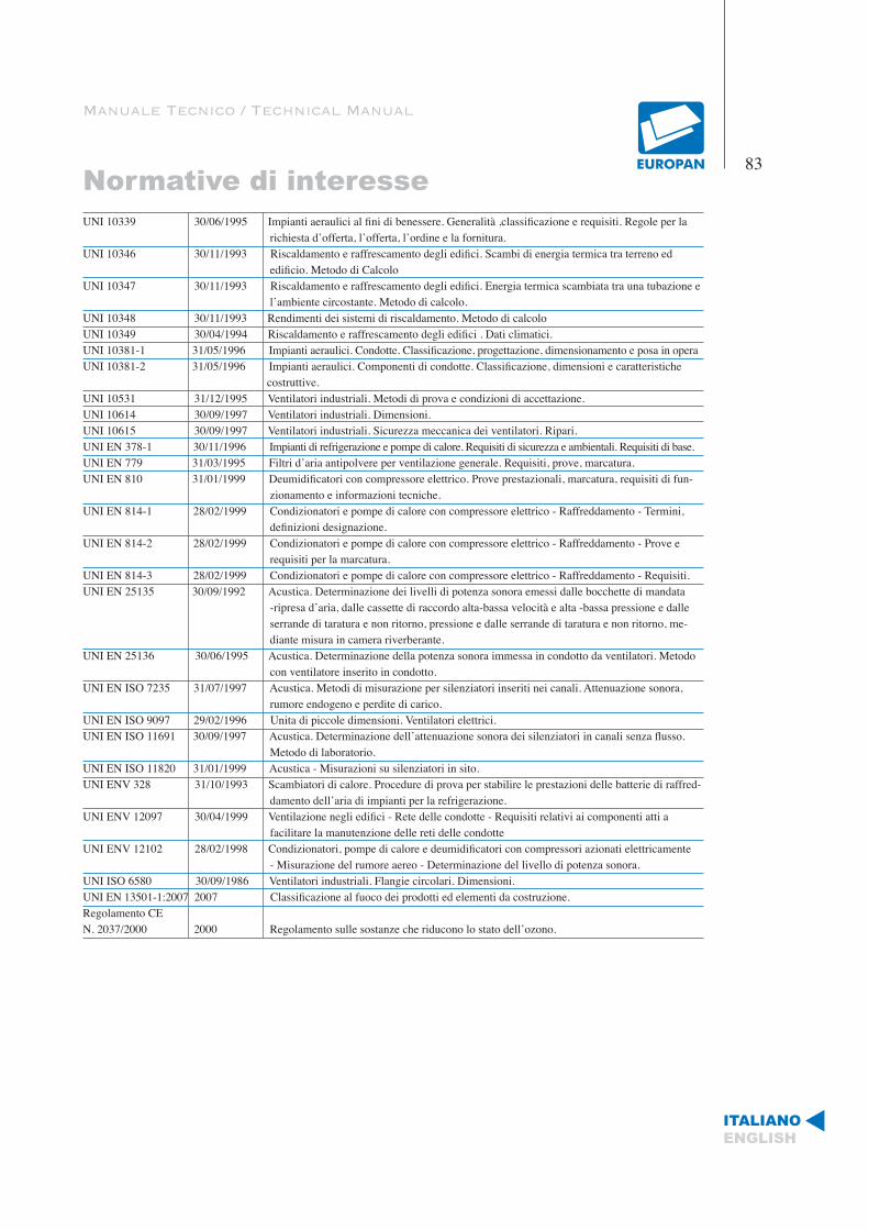
Manuale Tecnico / Technical Manual
Normative di interesse83
ITALIANOENGLISH
UNI 10339 30/06/1995 Impianti aeraulici al fini di benessere. Generalità ,classificazione e requisiti. Regole per la richiesta d’offerta, l’offerta, l’ordine e la fornitura.UNI 10346 30/11/1993 Riscaldamento e raffrescamento degli edifici. Scambi di energia termica tra terreno ed edificio. Metodo di CalcoloUNI 10347 30/11/1993 Riscaldamento e raffrescamento degli edifici. Energia termica scambiata tra una tubazione e l’ambiente circostante. Metodo di calcolo.UNI 10348 30/11/1993 Rendimenti dei sistemi di riscaldamento. Metodo di calcoloUNI 10349 30/04/1994 Riscaldamento e raffrescamento degli edifici . Dati climatici.UNI 10381-1 31/05/1996 Impianti aeraulici. Condotte. Classificazione, progettazione, dimensionamento e posa in operaUNI 10381-2 31/05/1996 Impianti aeraulici. Componenti di condotte. Classificazione, dimensioni e caratteristiche costruttive.UNI 10531 31/12/1995 Ventilatori industriali. Metodi di prova e condizioni di accettazione.UNI 10614 30/09/1997 Ventilatori industriali. Dimensioni.UNI 10615 30/09/1997 Ventilatori industriali. Sicurezza meccanica dei ventilatori. Ripari.UNI EN 378-1 30/11/1996 Impianti di refrigerazione e pompe di calore. Requisiti di sicurezza e ambientali. Requisiti di base.UNI EN 779 31/03/1995 Filtri d’aria antipolvere per ventilazione generale. Requisiti, prove, marcatura.UNI EN 810 31/01/1999 Deumidificatori con compressore elettrico. Prove prestazionali, marcatura, requisiti di fun- zionamento e informazioni tecniche.UNI EN 814-1 28/02/1999 Condizionatori e pompe di calore con compressore elettrico - Raffreddamento - Termini, definizioni designazione.UNI EN 814-2 28/02/1999 Condizionatori e pompe di calore con compressore elettrico - Raffreddamento - Prove e requisiti per la marcatura.UNI EN 814-3 28/02/1999 Condizionatori e pompe di calore con compressore elettrico - Raffreddamento - Requisiti.UNI EN 25135 30/09/1992 Acustica. Determinazione dei livelli di potenza sonora emessi dalle bocchette di mandata -ripresa d’aria, dalle cassette di raccordo alta-bassa velocità e alta -bassa pressione e dalle serrande di taratura e non ritorno, pressione e dalle serrande di taratura e non ritorno, me- diante misura in camera riverberante.UNI EN 25136 30/06/1995 Acustica. Determinazione della potenza sonora immessa in condotto da ventilatori. Metodo con ventilatore inserito in condotto.UNI EN ISO 7235 31/07/1997 Acustica. Metodi di misurazione per silenziatori inseriti nei canali. Attenuazione sonora, rumore endogeno e perdite di carico.UNI EN ISO 9097 29/02/1996 Unita di piccole dimensioni. Ventilatori elettrici.UNI EN ISO 11691 30/09/1997 Acustica. Determinazione dell’attenuazione sonora dei silenziatori in canali senza flusso. Metodo di laboratorio.UNI EN ISO 11820 31/01/1999 Acustica - Misurazioni su silenziatori in sito.UNI ENV 328 31/10/1993 Scambiatori di calore. Procedure di prova per stabilire le prestazioni delle batterie di raffred- damento dell’aria di impianti per la refrigerazione.UNI ENV 12097 30/04/1999 Ventilazione negli edifici - Rete delle condotte - Requisiti relativi ai componenti atti a facilitare la manutenzione delle reti delle condotteUNI ENV 12102 28/02/1998 Condizionatori, pompe di calore e deumidificatori con compressori azionati elettricamente - Misurazione del rumore aereo - Determinazione del livello di potenza sonora.UNI ISO 6580 30/09/1986 Ventilatori industriali. Flangie circolari. Dimensioni.UNI EN 13501-1:2007 2007 Classificazione al fuoco dei prodotti ed elementi da costruzione.Regolamento CE N. 2037/2000 2000 Regolamento sulle sostanze che riducono lo stato dell’ozono.

84
Cenni per un corretto utilizzo del manuale tecnico
Le informazioni stilate all’interno del manuale non costituiscono standard di qualità.La finalità per cui è stato sviluppato è quella di poter disporre di un ma-nuale tecnico/pratico di facile apprendimento riguardo alle tecniche di mon-taggio e lavorazione dei prodotti EUROPAN, per quanti operano nel settore delle reti aerauliche.EUROPAN non assume nessuna responsabilità per le applicazioni dei prin-cipi e delle tecniche presenti all’interno di questo manuale, esse dipendono esclusivamente dalla scelta del progettista. La EUROPAN si riserva di variare a propria discrezione i contenuti del presente manuale in successive edizioni o mediante supplementi. Nella progettazione e realizzazione di reti aerauliche dovranno essere rispettate le leggi e i regolamenti emanati dalle autorità com-petenti.Il logotipo EUROPAN è stato registrato è appartiene esclusivamente alla EUROPAN S.r.l. e rappresenta l’identificazione dell’azienda. La EUROPAN vieta l’uso improprio del logo e la riproduzione anche parziale del presente catalogo in base ai termini di legge copyright by Euro.Pan Srl-Cosenza-Italy.
Notes for a correct use of the technical manual
The information found inside this technical manual does not constitute a stan-dard of quality. The purpose why it has been developed is to have a prac-tical/technical manual of easy learning regarding the techniques of working and mounting of the EUROPAN products, for whom is operating in aeraulic nets. EUROPAN does not assume any responsibility for the applications of the principles and the techniques present inside this technical manual, they depend exclusively by the choice of the planner. EUROPAN reserves the right to change at its own discretion the contents of the present technical manual in future editions or by supplements. In the planning and realization of aeraulic nets must be respected the laws and the rules issued by competent authorities. EUROPAN logo has been registered and belongs exclusively to the EUROPAN S.r.l. The logo represents the identification of EUROPAN. EUROPAN prohibits the improper use of the logo and even the partial reproduction of the present catalogue in base of the copyright law terms by Euro.Pan Srl-Cosenza-Italy.