Manuale per stampa - griven.com · presente manuale. 1.1.2Installazione ... • GRIVEN Srl...
32
DUNE FC AL1760 - AL1762 - AL1764 Manuale di istruzioni Instructions manual
-
Upload
vuongnguyet -
Category
Documents
-
view
221 -
download
0
Transcript of Manuale per stampa - griven.com · presente manuale. 1.1.2Installazione ... • GRIVEN Srl...
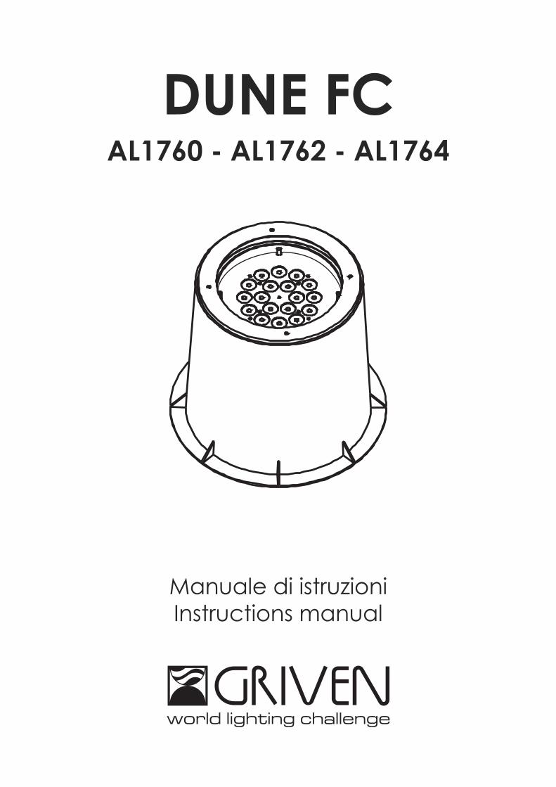
DUNE FCAL1760 - AL1762 - AL1764
Manuale di istruzioniInstructions manual
INDICE
1.0 Introduzione . . . . . . . . . . . . . . . . . . . . . . . . . . . . . . . . . . . . . . . . . . . . . . . . . . . . . . . . . . . . . . . . .41.1 Informazioni di sicurezza . . . . . . . . . . . . . . . . . . . . . . . . . . . . . . . . . . . . . . . . . . . . . . . . . . . . . . . . . . . . . . . . . . . .41.1.1 Protezione da scariche elettriche . . . . . . . . . . . . . . . . . . . . . . . . . . . . . . . . . . . . . . . . . . . . . . . . . . . . . . . . .41.1.2 Installazione . . . . . . . . . . . . . . . . . . . . . . . . . . . . . . . . . . . . . . . . . . . . . . . . . . . . . . . . . . . . . . . . . . . . . . . . . .41.1.3 Protezione dagli incendi . . . . . . . . . . . . . . . . . . . . . . . . . . . . . . . . . . . . . . . . . . . . . . . . . . . . . . . . . . . . . . . .41.1.4 Protezione da solidi e liquidi . . . . . . . . . . . . . . . . . . . . . . . . . . . . . . . . . . . . . . . . . . . . . . . . . . . . . . . . . . . . .4
1.2 Condizioni di garanzia . . . . . . . . . . . . . . . . . . . . . . . . . . . . . . . . . . . . . . . . . . . . . . . . . . . . . . . . . . . . . . . . . . . . . .41.3 Normative . . . . . . . . . . . . . . . . . . . . . . . . . . . . . . . . . . . . . . . . . . . . . . . . . . . . . . . . . . . . . . . . . . . . . . . . . . . . . . . .4
2.0 Dimensioni . . . . . . . . . . . . . . . . . . . . . . . . . . . . . . . . . . . . . . . . . . . . . . . . . . . . . . . . . . . . . . . . . .53.0 Componenti del proiettore . . . . . . . . . . . . . . . . . . . . . . . . . . . . . . . . . . . . . . . . . . . . . . . . . . . . .54.0 Avviamento rapido . . . . . . . . . . . . . . . . . . . . . . . . . . . . . . . . . . . . . . . . . . . . . . . . . . . . . . . . . . .65.0 Imballo e trasporto . . . . . . . . . . . . . . . . . . . . . . . . . . . . . . . . . . . . . . . . . . . . . . . . . . . . . . . . . . .75.1 Imballo . . . . . . . . . . . . . . . . . . . . . . . . . . . . . . . . . . . . . . . . . . . . . . . . . . . . . . . . . . . . . . . . . . . . . . . . . . . . . . . . . . .75.2 Trasporto . . . . . . . . . . . . . . . . . . . . . . . . . . . . . . . . . . . . . . . . . . . . . . . . . . . . . . . . . . . . . . . . . . . . . . . . . . . . . . . . .7
6.0 Installazione . . . . . . . . . . . . . . . . . . . . . . . . . . . . . . . . . . . . . . . . . . . . . . . . . . . . . . . . . . . . . . . . .76.1 Specifiche per l’incasso . . . . . . . . . . . . . . . . . . . . . . . . . . . . . . . . . . . . . . . . . . . . . . . . . . . . . . . . . . . . . . . . . . . . .76.2 Orientamento del fascio di luce . . . . . . . . . . . . . . . . . . . . . . . . . . . . . . . . . . . . . . . . . . . . . . . . . . . . . . . . . . . . . .86.3 Collegamento della tensione di alimentazione . . . . . . . . . . . . . . . . . . . . . . . . . . . . . . . . . . . . . . . . . . . . . . . . .96.4 Collegamento del segnale DMX . . . . . . . . . . . . . . . . . . . . . . . . . . . . . . . . . . . . . . . . . . . . . . . . . . . . . . . . . . . . .96.5 Sostituzione dei gruppi ottici . . . . . . . . . . . . . . . . . . . . . . . . . . . . . . . . . . . . . . . . . . . . . . . . . . . . . . . . . . . . . . . .10
7.0 Utilizzo del proiettore . . . . . . . . . . . . . . . . . . . . . . . . . . . . . . . . . . . . . . . . . . . . . . . . . . . . . . . . .127.1 Impostazione modo di funzionamento . . . . . . . . . . . . . . . . . . . . . . . . . . . . . . . . . . . . . . . . . . . . . . . . . . . . . . .127.2 Impostazione indirizzo DMX . . . . . . . . . . . . . . . . . . . . . . . . . . . . . . . . . . . . . . . . . . . . . . . . . . . . . . . . . . . . . . . . .127.3 Funzioni DMX . . . . . . . . . . . . . . . . . . . . . . . . . . . . . . . . . . . . . . . . . . . . . . . . . . . . . . . . . . . . . . . . . . . . . . . . . . . . .137.3.1 Funzioni DMX con modalità 62 PRESET COLOURS = OFF . . . . . . . . . . . . . . . . . . . . . . . . . . . . . . . . . . . . . .137.3.2 Funzioni DMX con modalità 62 PRESET COLOURS = ON . . . . . . . . . . . . . . . . . . . . . . . . . . . . . . . . . . . . . .13
8.0 Funzionamento Master-Slave e Automatico . . . . . . . . . . . . . . . . . . . . . . . . . . . . . . . . . . . . .138.1 Configurazione MASTER . . . . . . . . . . . . . . . . . . . . . . . . . . . . . . . . . . . . . . . . . . . . . . . . . . . . . . . . . . . . . . . . . . . .148.2 Configurazione SLAVE . . . . . . . . . . . . . . . . . . . . . . . . . . . . . . . . . . . . . . . . . . . . . . . . . . . . . . . . . . . . . . . . . . . . .158.3 Configurazione AUTOMATICO . . . . . . . . . . . . . . . . . . . . . . . . . . . . . . . . . . . . . . . . . . . . . . . . . . . . . . . . . . . . . . .15
9.0 Protezione termica . . . . . . . . . . . . . . . . . . . . . . . . . . . . . . . . . . . . . . . . . . . . . . . . . . . . . . . . . . .1510.0 Manutenzione . . . . . . . . . . . . . . . . . . . . . . . . . . . . . . . . . . . . . . . . . . . . . . . . . . . . . . . . . . . . .1510.1 Pulizia del proiettore . . . . . . . . . . . . . . . . . . . . . . . . . . . . . . . . . . . . . . . . . . . . . . . . . . . . . . . . . . . . . . . . . . . . . .1510.2 Controlli periodici . . . . . . . . . . . . . . . . . . . . . . . . . . . . . . . . . . . . . . . . . . . . . . . . . . . . . . . . . . . . . . . . . . . . . . . .15
11.0 Parti di ricambio . . . . . . . . . . . . . . . . . . . . . . . . . . . . . . . . . . . . . . . . . . . . . . . . . . . . . . . . . . . .1512.0 Ricerca dei guasti . . . . . . . . . . . . . . . . . . . . . . . . . . . . . . . . . . . . . . . . . . . . . . . . . . . . . . . . . .1613.0 Smaltimento dell’apparecchiatura . . . . . . . . . . . . . . . . . . . . . . . . . . . . . . . . . . . . . . . . . . . .1614.0 Specifiche tecniche . . . . . . . . . . . . . . . . . . . . . . . . . . . . . . . . . . . . . . . . . . . . . . . . . . . . . . . .17
INDEX
1.0 Introduction . . . . . . . . . . . . . . . . . . . . . . . . . . . . . . . . . . . . . . . . . . . . . . . . . . . . . . . . . . . . . . . .181.1 Safety information . . . . . . . . . . . . . . . . . . . . . . . . . . . . . . . . . . . . . . . . . . . . . . . . . . . . . . . . . . . . . . . . . . . . . . . . .181.1.1 Protecting against electric shock . . . . . . . . . . . . . . . . . . . . . . . . . . . . . . . . . . . . . . . . . . . . . . . . . . . . . . . .181.1.2 Installation . . . . . . . . . . . . . . . . . . . . . . . . . . . . . . . . . . . . . . . . . . . . . . . . . . . . . . . . . . . . . . . . . . . . . . . . . . .181.1.3 Protection against burns and fire . . . . . . . . . . . . . . . . . . . . . . . . . . . . . . . . . . . . . . . . . . . . . . . . . . . . . . . .181.1.4 Weather protection . . . . . . . . . . . . . . . . . . . . . . . . . . . . . . . . . . . . . . . . . . . . . . . . . . . . . . . . . . . . . . . . . . . .18
1.2 Warranty conditions . . . . . . . . . . . . . . . . . . . . . . . . . . . . . . . . . . . . . . . . . . . . . . . . . . . . . . . . . . . . . . . . . . . . . . .181.3 Compliance . . . . . . . . . . . . . . . . . . . . . . . . . . . . . . . . . . . . . . . . . . . . . . . . . . . . . . . . . . . . . . . . . . . . . . . . . . . . .18
2.0 Size . . . . . . . . . . . . . . . . . . . . . . . . . . . . . . . . . . . . . . . . . . . . . . . . . . . . . . . . . . . . . . . . . . . . . . .193.0 Components of the unit . . . . . . . . . . . . . . . . . . . . . . . . . . . . . . . . . . . . . . . . . . . . . . . . . . . . . . .194.0 Quick turn on . . . . . . . . . . . . . . . . . . . . . . . . . . . . . . . . . . . . . . . . . . . . . . . . . . . . . . . . . . . . . . .205.0 Packaging and transport . . . . . . . . . . . . . . . . . . . . . . . . . . . . . . . . . . . . . . . . . . . . . . . . . . . . .215.1 Packaging . . . . . . . . . . . . . . . . . . . . . . . . . . . . . . . . . . . . . . . . . . . . . . . . . . . . . . . . . . . . . . . . . . . . . . . . . . . . . . .215.2 Transport . . . . . . . . . . . . . . . . . . . . . . . . . . . . . . . . . . . . . . . . . . . . . . . . . . . . . . . . . . . . . . . . . . . . . . . . . . . . . . . .21
6.0 Installation . . . . . . . . . . . . . . . . . . . . . . . . . . . . . . . . . . . . . . . . . . . . . . . . . . . . . . . . . . . . . . . . .216.1 Build in specifications . . . . . . . . . . . . . . . . . . . . . . . . . . . . . . . . . . . . . . . . . . . . . . . . . . . . . . . . . . . . . . . . . . . . . .216.2 Adjusting light beam direction . . . . . . . . . . . . . . . . . . . . . . . . . . . . . . . . . . . . . . . . . . . . . . . . . . . . . . . . . . . . . .226.3 Connection to mains power . . . . . . . . . . . . . . . . . . . . . . . . . . . . . . . . . . . . . . . . . . . . . . . . . . . . . . . . . . . . . . . .236.4 Connection to DMX signal . . . . . . . . . . . . . . . . . . . . . . . . . . . . . . . . . . . . . . . . . . . . . . . . . . . . . . . . . . . . . . . . . .236.5 Replacing the optic groups . . . . . . . . . . . . . . . . . . . . . . . . . . . . . . . . . . . . . . . . . . . . . . . . . . . . . . . . . . . . . . . . .24
7.0 Use of the unit . . . . . . . . . . . . . . . . . . . . . . . . . . . . . . . . . . . . . . . . . . . . . . . . . . . . . . . . . . . . . . .267.1 Setting operating mode . . . . . . . . . . . . . . . . . . . . . . . . . . . . . . . . . . . . . . . . . . . . . . . . . . . . . . . . . . . . . . . . . . . .267.2 Setting DMX address . . . . . . . . . . . . . . . . . . . . . . . . . . . . . . . . . . . . . . . . . . . . . . . . . . . . . . . . . . . . . . . . . . . . . .267.3 DMX functions . . . . . . . . . . . . . . . . . . . . . . . . . . . . . . . . . . . . . . . . . . . . . . . . . . . . . . . . . . . . . . . . . . . . . . . . . . . .277.3.1 DMX functions with 62 PRESET COLOURS = OFF . . . . . . . . . . . . . . . . . . . . . . . . . . . . . . . . . . . . . . . . . . . . .277.3.2 DMX functions with 62 PRESET COLOURS = ON . . . . . . . . . . . . . . . . . . . . . . . . . . . . . . . . . . . . . . . . . . . . . .27
8.0 Master-Slave and Automatic function . . . . . . . . . . . . . . . . . . . . . . . . . . . . . . . . . . . . . . . . . . .278.1 MASTER configuration . . . . . . . . . . . . . . . . . . . . . . . . . . . . . . . . . . . . . . . . . . . . . . . . . . . . . . . . . . . . . . . . . . . . . .288.2 SLAVE configuration . . . . . . . . . . . . . . . . . . . . . . . . . . . . . . . . . . . . . . . . . . . . . . . . . . . . . . . . . . . . . . . . . . . . . . .298.3 AUTOMATIC configuration . . . . . . . . . . . . . . . . . . . . . . . . . . . . . . . . . . . . . . . . . . . . . . . . . . . . . . . . . . . . . . . . . .29
9.0 Thermal protection . . . . . . . . . . . . . . . . . . . . . . . . . . . . . . . . . . . . . . . . . . . . . . . . . . . . . . . . . .2910.0 Maintenance . . . . . . . . . . . . . . . . . . . . . . . . . . . . . . . . . . . . . . . . . . . . . . . . . . . . . . . . . . . . . .2910.1 Cleaning the unit . . . . . . . . . . . . . . . . . . . . . . . . . . . . . . . . . . . . . . . . . . . . . . . . . . . . . . . . . . . . . . . . . . . . . . . .2910.2 Regular checks . . . . . . . . . . . . . . . . . . . . . . . . . . . . . . . . . . . . . . . . . . . . . . . . . . . . . . . . . . . . . . . . . . . . . . . . . .29
11.0 Spare parts . . . . . . . . . . . . . . . . . . . . . . . . . . . . . . . . . . . . . . . . . . . . . . . . . . . . . . . . . . . . . . . .2912.0 Troubleshooting . . . . . . . . . . . . . . . . . . . . . . . . . . . . . . . . . . . . . . . . . . . . . . . . . . . . . . . . . . . .3013.0 Disposal . . . . . . . . . . . . . . . . . . . . . . . . . . . . . . . . . . . . . . . . . . . . . . . . . . . . . . . . . . . . . . . . . . .3014.0 Technical specifications . . . . . . . . . . . . . . . . . . . . . . . . . . . . . . . . . . . . . . . . . . . . . . . . . . . . .31

4 Italiano
1.1 Informazioni di sicurezza
1.1.1 Protezione da scariche elettriche• Togliere l’alimentazione prima di effettuare qualsiasi operazione all’interno dell’apparecchiatura.• Non utilizzate l’apparecchiatura in assenza di una connessione di terra.• Prima di connettere l’apparecchio alla rete elettrica, verificate la compatibilità di tensione e frequenza.• Non maneggiate il prodotto con mani bagnate o in presenza di acqua.• Controllate periodicamente che il cavo di alimentazione non sia schiacciato o danneggiato.• Rivolgersi ad un tecnico qualificato per qualsiasi operazione di manutenzione ordinaria non descritta nel
presente manuale.
1.1.2 Installazione• Le operazioni di installazione dell’apparecchiatura devono essere eseguite da personale competente e
qualificato.
1.1.3 Protezione dagli incendi
• Idoneo ad essere installato su superfici normalmente infiammabili.
1.1.4 Protezione da solidi e liquidiIl proiettore rientra nella classificazione di apparecchio con grado di protezione IP67.
1.2 Condizioni di garanzia• Ogni articolo prodotto dalla ditta italiana GRIVEN Srl è stato assemblato e costruito in conformità alle vigenti
norme e normative CE.• Ogni singolo prodotto e componente sono stati testati prima dell’assemblaggio finale ed ogni prodotto è sot-
toposto ad un controllo di qualità interno prima di essere spedito.• GRIVEN Srl garantisce la buona qualità e realizzazione dei propri prodotti e si impegna a riparare o sostituire a
propria discrezione, nel più breve tempo possibile, qualsiasi parte che – durante il periodo di garanzia – mostridifetti di costruzione, assemblaggio o materiale.
• La garanzia è valida per la durata di 12 (dodici) mesi dalla data di consegna del prodotto.• GRIVEN Srl non risponde dei danni riportati dal prodotto durante il trasporto oppure derivanti da un utilizzo im-
proprio o da un’inappropriata manutenzione dello stesso.• Sono escluse dalla presente garanzia tutte le parti considerate di consumo o soggette a normale logorio.• Il cliente dovrà restituire le parti difettose alla GRIVEN Srl a suo carico e rischio.• Le parti riparate o sostituire verranno spedite dalla GRIVEN ex-factory.• Per ogni controversia sarà competente il foro di Mantova (Italia) in conformità alla relativa giurisdizione italiana.
1.3 Normative
• L’apparecchio soddisfa i requisiti della normativa EN60598-1.• L’apparecchio soddisfa i requisiti della direttiva 2002/95/CE (RoHS).
Attenzione!Questo prodotto è adatto solo ad un uso professionale, non ad un uso domestico.
1.0 Introduzione
Italiano 5
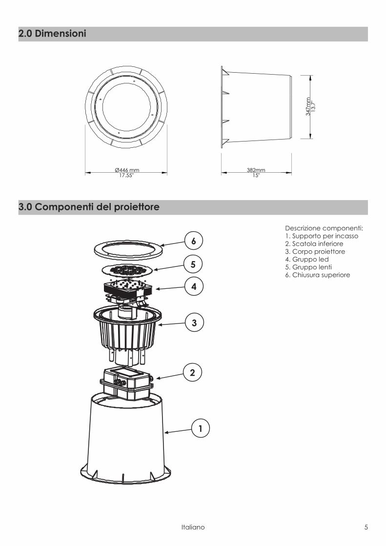
Descrizione componenti:1. Supporto per incasso2. Scatola inferiore3. Corpo proiettore4. Gruppo led5. Gruppo lenti6. Chiusura superiore
1
2
3
5
4
6
3.0 Componenti del proiettore
Ø446 mm17.55"
382mm15"
347m
m13
.7"
2.0 Dimensioni
6 Italiano
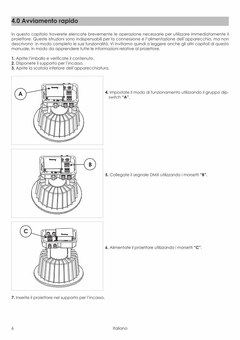
In questo capitolo troverete elencate brevemente le operazione necessarie per utilizzare immediatamente ilproiettore. Queste istruzioni sono indispensabili per la connessione e l’alimentazione dell’apparecchio, ma nondescrivono in modo completo le sue funzionalità. Vi invitiamo quindi a leggere anche gli altri capitoli di questomanuale, in modo da apprendere tutte le informazioni relative al proiettore.
1. Aprite l’imballo e verificate il contenuto.2. Disponete il supporto per l’incasso.3. Aprite la scatola inferiore dell’apparecchiatura.
4. Impostate il modo di funzionamento utilizzando il gruppo dip-switch “A”.
5. Collegate il segnale DMX utilizzando i morsetti “B”.
6. Alimentate il proiettore utilizzando i morsetti “C”.
7. Inserite il proiettore nel supporto per l’incasso.
C
B
A
4.0 Avviamento rapido

Italiano 7
5.1 ImballoControllate attentamente il contenuto del cartone e, in caso di danni al prodotto, contattate il Vs. trasportatore.Nell’imballaggio del presente proiettore sono contenuti i seguenti prodotti:
n° 1 proiettore DUNE FCn° 1 manuale di istruzioni
5.2 TrasportoSi raccomanda di trasportare l’apparecchiatura con estrema attenzione, utilizzando il suo imballo originale perevitare di danneggiare il prodotto.
6.1 Specifiche per l’incasso
Max 20 Km/h
Max 2000 Kg
6.0 Installazione
Attenzione!• La responsabilità di Griven S.r.l. cessa all’atto della consegna del materiale al vettore: reclami per eventuali
danni dovuti al trasporto dovranno essere indirizzati direttamente al corriere.• Si accettano reclami entro e non oltre i 7 giorni dal ricevimento della merce.• Eventuali resi di materiale dovranno essere autorizzati da Griven S.r.l. ed inviati completi della documentazione
fiscale necessaria.
5.0 Imballo e trasporto
8 Italiano
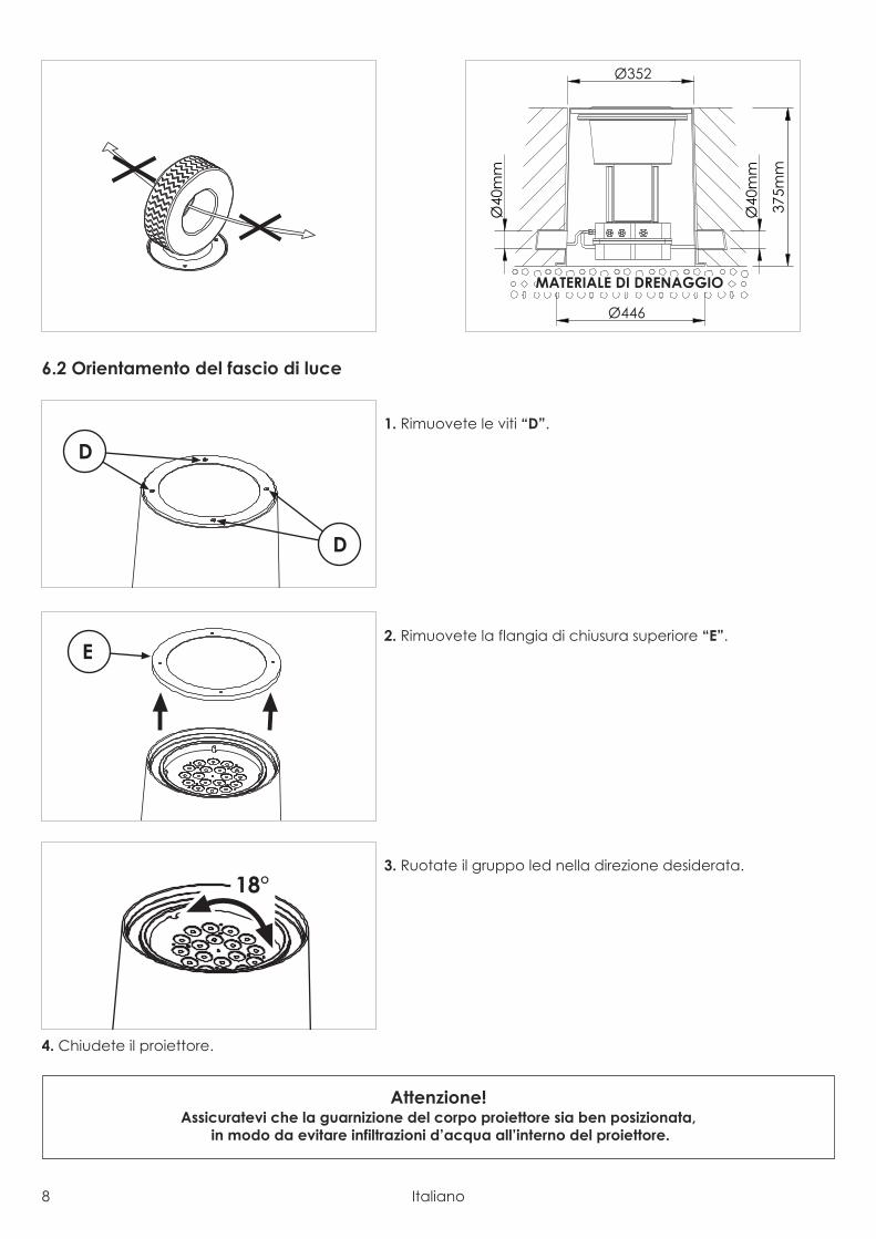
6.2 Orientamento del fascio di luce
1. Rimuovete le viti “D”.
2. Rimuovete la flangia di chiusura superiore “E”.
3. Ruotate il gruppo led nella direzione desiderata.
4. Chiudete il proiettore.
Attenzione!Assicuratevi che la guarnizione del corpo proiettore sia ben posizionata,
in modo da evitare infiltrazioni d’acqua all’interno del proiettore.
18°
Ø446
Ø352
Ø40
mm
Ø40
mm
375m
m
MATERIALE DI DRENAGGIO
E
D
D
Italiano 9
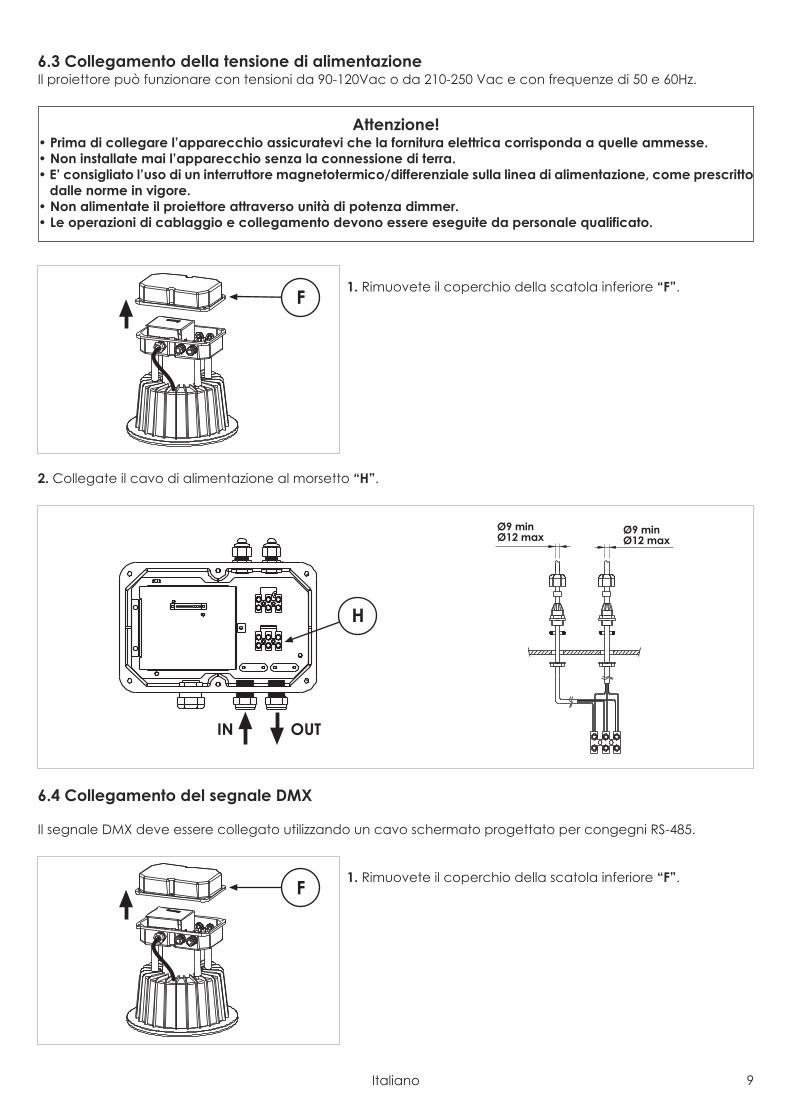
6.3 Collegamento della tensione di alimentazioneIl proiettore può funzionare con tensioni da 90-120Vac o da 210-250 Vac e con frequenze di 50 e 60Hz.
1. Rimuovete il coperchio della scatola inferiore “F”.
2. Collegate il cavo di alimentazione al morsetto “H”.
6.4 Collegamento del segnale DMX
Il segnale DMX deve essere collegato utilizzando un cavo schermato progettato per congegni RS-485.
1. Rimuovete il coperchio della scatola inferiore “F”.F
IN OUT
H
Ø9 minØ12 max
Ø9 minØ12 max
F
Attenzione!• Prima di collegare l’apparecchio assicuratevi che la fornitura elettrica corrisponda a quelle ammesse.• Non installate mai l’apparecchio senza la connessione di terra.• E’ consigliato l’uso di un interruttore magnetotermico/differenziale sulla linea di alimentazione, come prescritto
dalle norme in vigore.• Non alimentate il proiettore attraverso unità di potenza dimmer.• Le operazioni di cablaggio e collegamento devono essere eseguite da personale qualificato.
10 Italiano
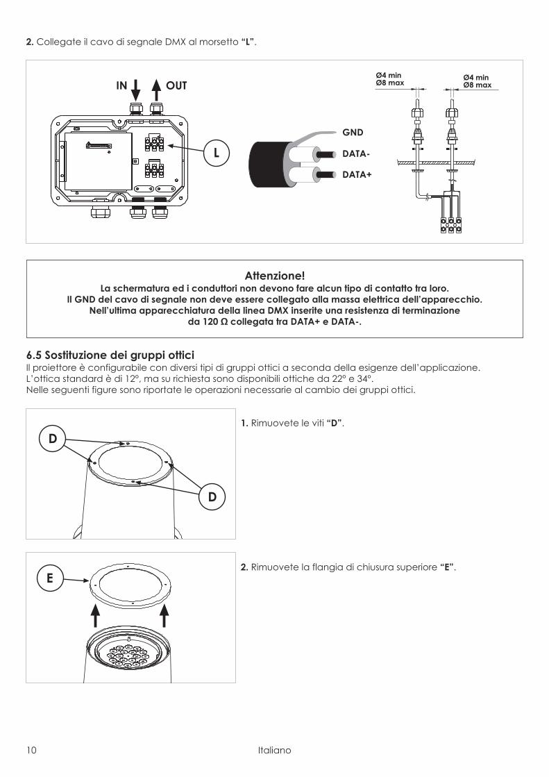
2. Collegate il cavo di segnale DMX al morsetto “L”.
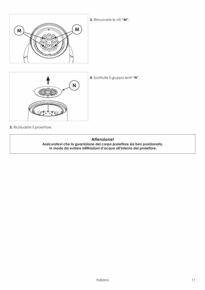
6.5 Sostituzione dei gruppi otticiIl proiettore è configurabile con diversi tipi di gruppi ottici a seconda della esigenze dell’applicazione.L’ottica standard è di 12°, ma su richiesta sono disponibili ottiche da 22° e 34°.Nelle seguenti figure sono riportate le operazioni necessarie al cambio dei gruppi ottici.
1. Rimuovete le viti “D”.
2. Rimuovete la flangia di chiusura superiore “E”.E
D
D
Attenzione!La schermatura ed i conduttori non devono fare alcun tipo di contatto tra loro.
Il GND del cavo di segnale non deve essere collegato alla massa elettrica dell’apparecchio.Nell’ultima apparecchiatura della linea DMX inserite una resistenza di terminazione
da 120 Ω collegata tra DATA+ e DATA-.
IN OUT
GND
DATA-
DATA+
L
Ø4 minØ8 max
Ø4 minØ8 max
Italiano 11
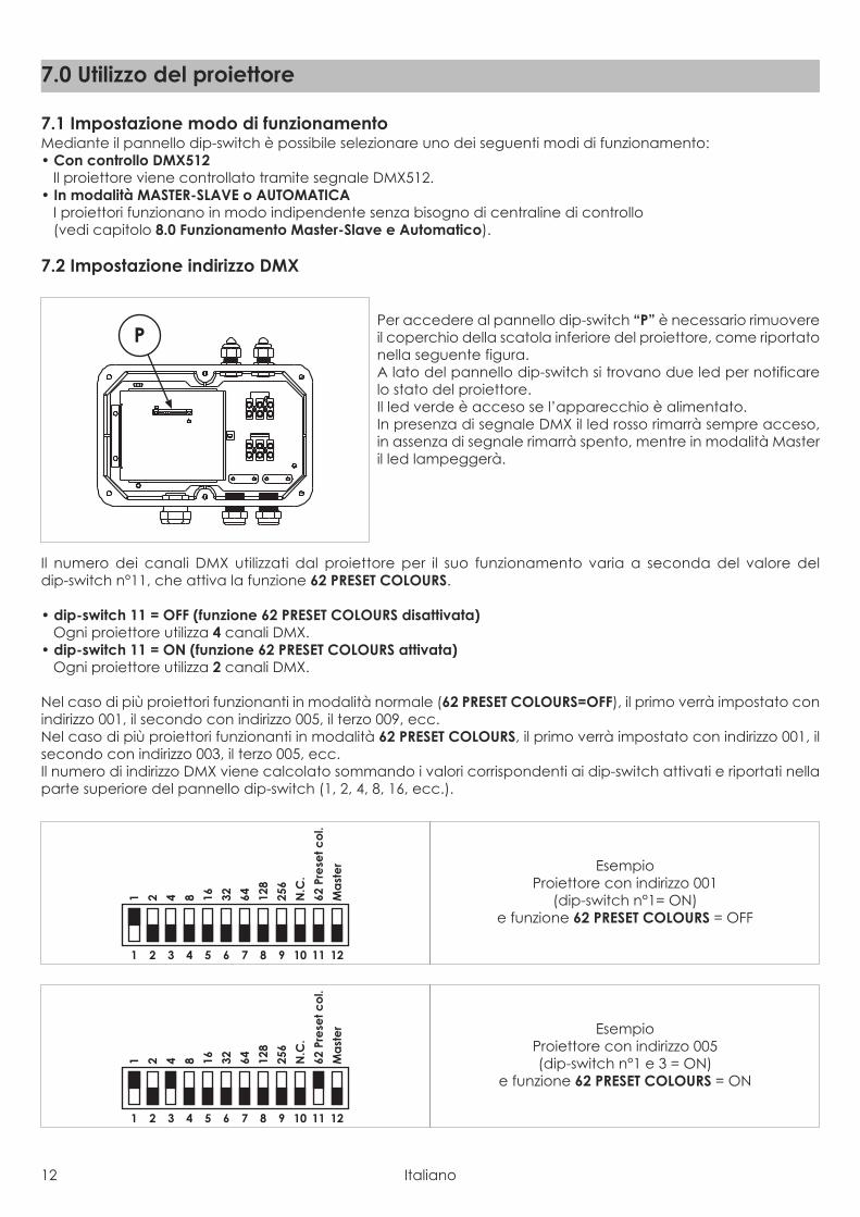
3. Rimuovete le viti “M”.
4. Sostituite il gruppo lenti “N”.
5. Richiudete il proiettore.
Attenzione!Assicuratevi che la guarnizione del corpo proiettore sia ben posizionata,
in modo da evitare infiltrazioni d’acqua all’interno del proiettore.
N
M M
12 Italiano
7.1 Impostazione modo di funzionamentoMediante il pannello dip-switch è possibile selezionare uno dei seguenti modi di funzionamento:• Con controllo DMX512
Il proiettore viene controllato tramite segnale DMX512.• In modalità MASTER-SLAVE o AUTOMATICA
I proiettori funzionano in modo indipendente senza bisogno di centraline di controllo(vedi capitolo 8.0 Funzionamento Master-Slave e Automatico).
7.2 Impostazione indirizzo DMX
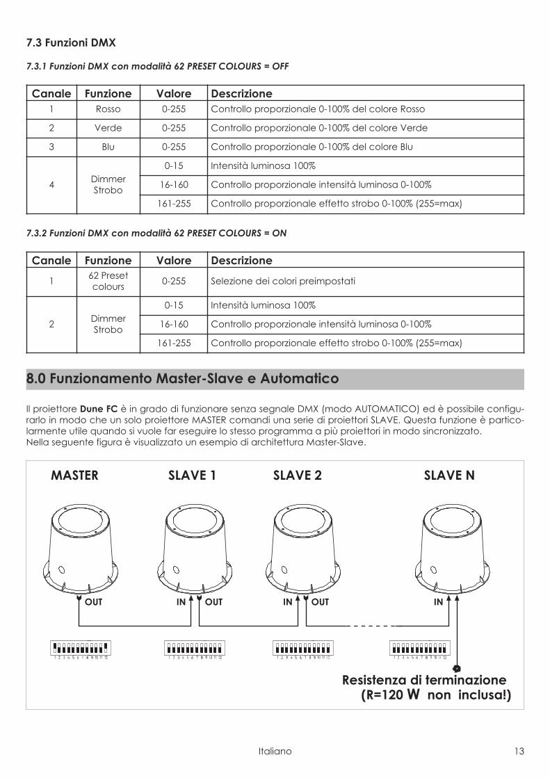
Per accedere al pannello dip-switch “P” è necessario rimuovereil coperchio della scatola inferiore del proiettore, come riportatonella seguente figura.A lato del pannello dip-switch si trovano due led per notificarelo stato del proiettore.Il led verde è acceso se l’apparecchio è alimentato.In presenza di segnale DMX il led rosso rimarrà sempre acceso,in assenza di segnale rimarrà spento, mentre in modalità Masteril led lampeggerà.
Il numero dei canali DMX utilizzati dal proiettore per il suo funzionamento varia a seconda del valore deldip-switch n°11, che attiva la funzione 62 PRESET COLOURS.
• dip-switch 11 = OFF (funzione 62 PRESET COLOURS disattivata)Ogni proiettore utilizza 4 canali DMX.
• dip-switch 11 = ON (funzione 62 PRESET COLOURS attivata)Ogni proiettore utilizza 2 canali DMX.
Nel caso di più proiettori funzionanti in modalità normale (62 PRESET COLOURS=OFF), il primo verrà impostato conindirizzo 001, il secondo con indirizzo 005, il terzo 009, ecc.Nel caso di più proiettori funzionanti in modalità 62 PRESET COLOURS, il primo verrà impostato con indirizzo 001, ilsecondo con indirizzo 003, il terzo 005, ecc.Il numero di indirizzo DMX viene calcolato sommando i valori corrispondenti ai dip-switch attivati e riportati nellaparte superiore del pannello dip-switch (1, 2, 4, 8, 16, ecc.).
1 2 3 4 5 6 7 8 9 10 11 12
1 2 4 8 16 32 64 128
256
N.C
.
62Pr
ese
tco
l.
Ma
ste
r EsempioProiettore con indirizzo 005(dip-switch n°1 e 3 = ON)
e funzione 62 PRESET COLOURS = ON
1 2 3 4 5 6 7 8 9 10 11 12
1 2 4 8 16 32 64 128
256
N.C
.
62Pr
ese
tco
l.
Ma
ste
r EsempioProiettore con indirizzo 001
(dip-switch n°1= ON)e funzione 62 PRESET COLOURS = OFF
P
7.0 Utilizzo del proiettore
Italiano 13
7.3 Funzioni DMX
7.3.1 Funzioni DMX con modalità 62 PRESET COLOURS = OFF
7.3.2 Funzioni DMX con modalità 62 PRESET COLOURS = ON
Il proiettore Dune FC è in grado di funzionare senza segnale DMX (modo AUTOMATICO) ed è possibile configu-rarlo in modo che un solo proiettore MASTER comandi una serie di proiettori SLAVE. Questa funzione è partico-larmente utile quando si vuole far eseguire lo stesso programma a più proiettori in modo sincronizzato.Nella seguente figura è visualizzato un esempio di architettura Master-Slave.
MASTER SLAVE 1 SLAVE N
INOUTINOUT
SLAVE 2
INOUT
Resistenza di terminazione(R=120 W non inclusa!)
8.0 Funzionamento Master-Slave e Automatico
Canale Funzione Valore Descrizione
1 62 Presetcolours 0-255 Selezione dei colori preimpostati
2 DimmerStrobo
0-15 Intensità luminosa 100%
16-160 Controllo proporzionale intensità luminosa 0-100%
161-255 Controllo proporzionale effetto strobo 0-100% (255=max)
Canale Funzione Valore Descrizione1 Rosso 0-255 Controllo proporzionale 0-100% del colore Rosso
2 Verde 0-255 Controllo proporzionale 0-100% del colore Verde
3 Blu 0-255 Controllo proporzionale 0-100% del colore Blu
4 DimmerStrobo
0-15 Intensità luminosa 100%
16-160 Controllo proporzionale intensità luminosa 0-100%
161-255 Controllo proporzionale effetto strobo 0-100% (255=max)
14 Italiano
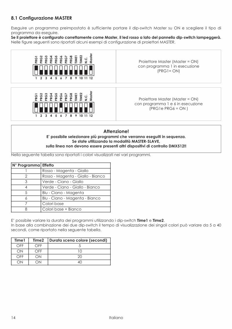
8.1 Configurazione MASTER
Eseguire un programma preimpostato è sufficiente portare il dip-switch Master su ON e scegliere il tipo diprogramma da eseguire.Se il proiettore è configurato correttamente come Master, il led rosso a lato del pannello dip-switch lampeggerà.Nelle figure seguenti sono riportati alcuni esempi di configurazione di proiettori MASTER.
Nella seguente tabella sono riportati i colori visualizzati nei vari programmi.
E’ possibile variare la durata dei programmi utilizzando i dip-switch Time1 e Time2.In base alla combinazione dei due dip-switch il tempo di visualizzazione dei singoli colori può variare da 5 a 40secondi, come riportato nella seguente tabella.
Time1 Time2 Durata scena colore (secondi)OFF OFF 5ON OFF 10OFF ON 20ON ON 40
N° Programma Effetto1 Rosso - Magenta - Giallo2 Rosso - Magenta - Giallo - Bianco3 Verde - Ciano - Giallo4 Verde - Ciano - Giallo - Bianco5 Blu - Ciano - Magenta6 Blu - Ciano - Magenta - Bianco7 Colori base8 Colori base + Bianco
Attenzione!E’ possibile selezionare più programmi che verranno eseguiti in sequenza.
Se state utilizzando la modalità MASTER-SLAVE,sulla linea non devono essere presenti altri dispositivi di controllo DMX512!!
1 2 3 4 5 6 7 8 9 10 11 12
PRG
1
PRG
2
PRG
3
PRG
4
PRG
5
PRG
6
PRG
7
PRG
8
TIM
E1
TIM
E2
N.C
.
Ma
ste
r
Proiettore Master (Master = ON)con programma 1 e 6 in esecuzione
(PRG1e PRG6 = ON )
1 2 3 4 5 6 7 8 9 10 11 12
PRG
1
PRG
2
PRG
3
PRG
4
PRG
5
PRG
6
PRG
7
PRG
8
TIM
E1
TIM
E2
N.C
.
Ma
ste
r
Proiettore Master (Master = ON)con programma 1 in esecuzione
(PRG1= ON)
Italiano 15
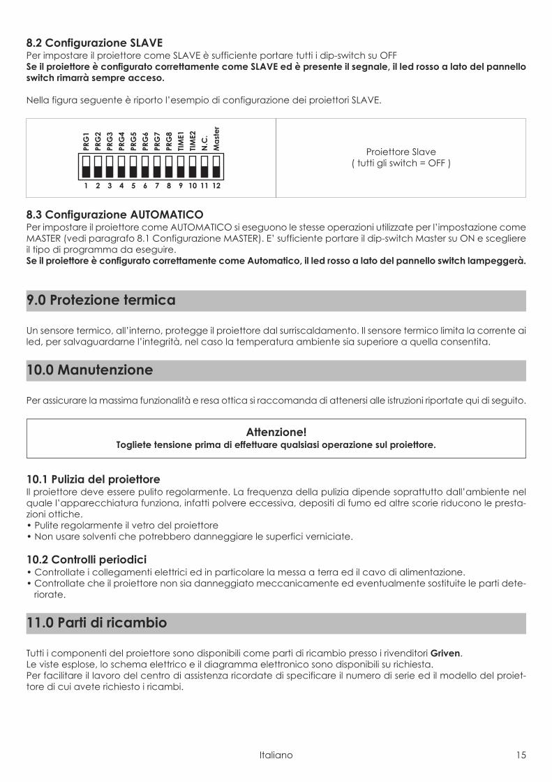
8.2 Configurazione SLAVEPer impostare il proiettore come SLAVE è sufficiente portare tutti i dip-switch su OFFSe il proiettore è configurato correttamente come SLAVE ed è presente il segnale, il led rosso a lato del pannelloswitch rimarrà sempre acceso.
Nella figura seguente è riporto l’esempio di configurazione dei proiettori SLAVE.
8.3 Configurazione AUTOMATICOPer impostare il proiettore come AUTOMATICO si eseguono le stesse operazioni utilizzate per l’impostazione comeMASTER (vedi paragrafo 8.1 Configurazione MASTER). E’ sufficiente portare il dip-switch Master su ON e scegliereil tipo di programma da eseguire.Se il proiettore è configurato correttamente come Automatico, il led rosso a lato del pannello switch lampeggerà.
Un sensore termico, all’interno, protegge il proiettore dal surriscaldamento. Il sensore termico limita la corrente ailed, per salvaguardarne l’integrità, nel caso la temperatura ambiente sia superiore a quella consentita.
Per assicurare la massima funzionalità e resa ottica si raccomanda di attenersi alle istruzioni riportate qui di seguito.
10.1 Pulizia del proiettoreIl proiettore deve essere pulito regolarmente. La frequenza della pulizia dipende soprattutto dall’ambiente nelquale l’apparecchiatura funziona, infatti polvere eccessiva, depositi di fumo ed altre scorie riducono le presta-zioni ottiche.• Pulite regolarmente il vetro del proiettore• Non usare solventi che potrebbero danneggiare le superfici verniciate.
10.2 Controlli periodici• Controllate i collegamenti elettrici ed in particolare la messa a terra ed il cavo di alimentazione.• Controllate che il proiettore non sia danneggiato meccanicamente ed eventualmente sostituite le parti dete-
riorate.
Tutti i componenti del proiettore sono disponibili come parti di ricambio presso i rivenditori Griven.Le viste esplose, lo schema elettrico e il diagramma elettronico sono disponibili su richiesta.Per facilitare il lavoro del centro di assistenza ricordate di specificare il numero di serie ed il modello del proiet-tore di cui avete richiesto i ricambi.
11.0 Parti di ricambio
Attenzione!Togliete tensione prima di effettuare qualsiasi operazione sul proiettore.
10.0 Manutenzione
9.0 Protezione termica
1 2 3 4 5 6 7 8 9 10 11 12
PRG
1
PRG
2
PRG
3
PRG
4
PRG
5
PRG
6
PRG
7
PRG
8
TIM
E1
TIM
E2
N.C
.
Ma
ste
r
Proiettore Slave( tutti gli switch = OFF )
16 Italiano
La direttiva Europea 2002/96/CE sui rifiuti di apparecchiature elettroniche (RAEE), prevede che gli apparecchiilluminanti non debbano essere smaltiti nel normale flusso dei rifiuti solidi urbani. Gli apparecchi dismessi debbonoessere raccolti separatamente per ottimizzare il tasso di recupero e riciclaggio dei materiali che li compongonoed impedire potenziali danni per la salute e l’ambiente.
Il simbolo del cestino barrato è riportato su tutti i prodotti per ricordare gli obblighi diraccolta separata.
Per ulteriori informazioni sulla corretta dismissione delle apparecchiature, i detentori potranno rivolgersi al serviziopubblico preposto o ai rivenditori.
13.0 Smaltimento dell’apparecchiatura
Problema Possibile causa ProvvedimentoIl led verde vicino alpannello dip-switchnon si accende.
Apparecchiatura nonalimentata.
Controllate che i cavi di alimentazione siano collegati eche ci sia tensione.
Scheda guasta. Verificare il funzionamento della scheda di controllo.
Il proiettore nonrisponde correttamenteal controllo DMX.
Collegamento caviDMX non corretto.
Ispezionare connessioni e cavi. Correggere le connessioniinefficienti. Riparare o sostituire i cavi danneggiati.
Collegamento dati nonterminato.
Inserire una resistenza di terminazione nel morsettodell’ultima apparecchiatura del collegamento.
Scorretta assegnazione diindirizzi dei proiettori.
Controllare gli indirizzi delle apparecchiature e leimpostazioni del protocollo.
Una delle apparecchiatureè difettosa e disturba latrasmissione di dati nelcollegamento.
Cortocircuitare un’apparecchiatura alla voltafino a quando il funzionamento normale non èripristinato.
Il proiettore è configuratocome Master , ma non ese-gue nessun programma.
E’ stata attivata la funzioneMaster, ma non è stato sele-zionato nessun programma.
Selezionare almeno un programma da eseguire.
Il proiettore è configuratocome Slave , ma nonrisponde correttamenteal Master.
Sono stati impostati piùMaster sulla linea
Verificare che solo un’apparecchio sia configuratocome Master.
Sulla linea è presente ilsegnale DMX. Verificare che non ci siano centraline DMX sulla linea.
12.0 Ricerca dei guasti
Italiano 17
Caratteristiche meccanicheAltezza . . . . . . . . . . . . . . . . . . . . . . . . . . . . . . . . . . . . . . . . . . . . . . . . . . . . . . . . . . . . . . . . . . . . . . . . . . . . . . . 382mm (15”)Ø Inferiore . . . . . . . . . . . . . . . . . . . . . . . . . . . . . . . . . . . . . . . . . . . . . . . . . . . . . . . . . . . . . . . . . . . . . . . . Ø446mm (17.55”)Ø Superiore . . . . . . . . . . . . . . . . . . . . . . . . . . . . . . . . . . . . . . . . . . . . . . . . . . . . . . . . . . . . . . . . . . . . . . . . Ø347mm (13.7”)Peso . . . . . . . . . . . . . . . . . . . . . . . . . . . . . . . . . . . . . . . . . . . . . . . . . . . . . . . . . . . . . . . . . . . . . . . . . . . . . . . . . . 12.2Kg (Lbs)Caratteristiche termicheMassima temperatura ambiente . . . . . . . . . . . . . . . . . . . . . . . . . . . . . . . . . . . . . . . . . . . . . . . . . . . . . . . . . 40°C (104°F)Massima temperatura superficiale . . . . . . . . . . . . . . . . . . . . . . . . . . . . . . . . . . . . . . . . . . . . . . . . . . . . . <60°C ( <140°F)Caratteristiche elettricheTensione di alimentazione . . . . . . . . . . . . . . . . . . . . . . . . . . . . . . . . . . . . . . . . . . . . 90-120 Vac / 210-250 Vac 50/60HzCorrente nominale . . . . . . . . . . . . . . . . . . . . . . . . . . . . . . . . . . . . . . . . . . . . . . . . . . . . . . . . . 1.2A @ 110V / 0.6A @ 230VPotenza massima . . . . . . . . . . . . . . . . . . . . . . . . . . . . . . . . . . . . . . . . . . . . . . . . . . . . . . . . . . . . . . . . . . . . . . . . . . . . . 75WProtezione termica . . . . . . . . . . . . . . . . . . . . . . . . . . . . . . . . . . . . . . . . . . . . . . . . . . . . . . . . . . . . . . . . . . . . . . ElettronicaSorgente luminosaTipo sorgente luminosa . . . . . . . . . . . . . . . . . . . . . . . . . . . . . . . . . . . . . . . . . . . . . . . . . . . . . . . . . . . . . . 18 Led RGB x 3WOtticaSistema ottico . . . . . . . . . . . . . . . . . . . . . . . . . . . . . . . . . . . . . . . . . . . . . . . . . . . . . . . . . . . . . . . . . . . . . . . . . . . . . . A lentiOttiche disponibili . . . . . . . . . . . . . . . . . . . . . . . . . . . . . . . . . . . . 12° cod. AL1760 / 28° cod. AL1762/ 40° cod. AL1764ControlloProtocollo . . . . . . . . . . . . . . . . . . . . . . . . . . . . . . . . . . . . . . . . . . . . . . . . . . . . . . . . . . . . . . . . . . . . . . . . . . . USITT DMX-512Canali di controllo . . . . . . . . . . . 4 canali DMX in modalità standard / 2 canali DMX in modalità 62 Preset coloursCostruzioneCorpo proiettore . . . . . . . . . . . . . . . . . . . . . . . . . . . . . . . . . . . . . . . . . . . . . . . . . . . . . . . . . . . . . . . . . . . . . . . . . . AlluminioTrattamento . . . . . . . . . . . . . . . . . . . . . . . . . . . . . . . . . . . . . . . . . . . . . . . . . . . . . . . . . . . . . . . . . . . . . Vernice antigraffioFattore di protezione . . . . . . . . . . . . . . . . . . . . . . . . . . . . . . . . . . . . . . . . . . . . . . . . . . . . . . . . . . . . . . . . . . . . . . . . . . . IP67
14.0 Specifiche tecniche
1.1 Safety information
1.1.1 Protecting against electric shock• Disconnect the unit from mains supply before servicing it or performing any other action.• Always ground/earth the unit electrically.• Before connecting the unit to power supplies, verify that operating voltage and frequency are compatible.• Do not handle the unit with wet hands or in the presence of water.• Check regularly that the power supply cable is not damaged or crushed.• Apply to a qualified technician for any regular maintenance action not described in this manual.
1.1.2 Installation• The unit installation actions must be performed by a qualified staff.
1.1.3 Protection against burns and fire
• Suitable to be installed onto normally inflammable surfaces.• The unit is not to be installed in places where the ambient temperature exceeds 40° (104°F).
1.1.4 Weather protectionThe unit is classified as device with an IP67 weather protection rate.
1.2 Warranty conditions• Each product manufactured by GRIVEN srl of Italy is assembled and built in accordance to current CE con-
formity rules and regulations.• Every single product and component has been tested before the final assembling and all products must pass
the in-house quality control before they are shipped.• GRIVEN srl of Italy guarantees the good quality and manufacture of the products and undertakes to repair or
supply again, according to his opinion and free of charge, within the shortest time possible, any part that shows- during the guarantee period - defects of constructions, manufacture or material.
• The guarantee is valid for 12 (twelve) months starting from the delivery date of the products.• GRIVEN srl of Italy does not respond for damages occurred to the units during transport and for irrational use and
inaccuracy in regular maintenance of the products.• The guarantee excludes all consumables.• The customer will take care of the return of the faulty parts to GRIVEN srl of Italy, at his own charge and risk.• The parts which have been repaired or replaced are sent by GRIVEN srl of Italy ex-factory.• For any dispute, the Court of Mantova (Italy) will be competent and in conformity with relevant jurisdiction the
Italian Law is enforced for any controversy.
1.3 Compliance
• Product in compliance with EN60598-1.• Product in compliance with 2002/95/CE (RoHS).
Warning!This unit is suitable for professional use only, not for domestic use.
1.0 Introduction
18 English

Components description:1. Supporto per incasso2. Lower box3. Body4. Led group5. Lens group6. Upper closing
1
2
3
5
4
6
3.0 Components of the unit
Ø446 mm17.55"
382mm15"
347m
m13
.7"
2.0 Size
English 19
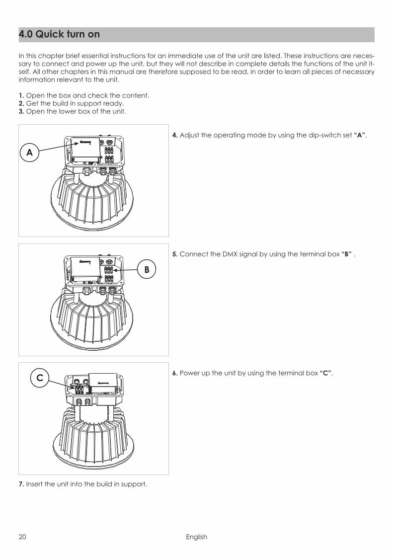
In this chapter brief essential instructions for an immediate use of the unit are listed. These instructions are neces-sary to connect and power up the unit, but they will not describe in complete details the functions of the unit it-self. All other chapters in this manual are therefore supposed to be read, in order to learn all pieces of necessaryinformation relevant to the unit.
1. Open the box and check the content.2. Get the build in support ready.3. Open the lower box of the unit.
4. Adjust the operating mode by using the dip-switch set “A”.
5. Connect the DMX signal by using the terminal box “B” .
6. Power up the unit by using the terminal box “C”.
7. Insert the unit into the build in support.
C
B
A
4.0 Quick turn on
20 English

5.1 PackagingCheck carefully the content of the box and, in case of damage, contact your forwarder immediately. The fol-lowing items are included in the box of this unit:
n° 1 DUNE FC unitn° 1 owner’s manual
5.2 TransportIt is recommended to transport the unit with the maximum care, by using its original packing, to avoid todamage the unit.
6.1 Build in specifications
Max 20 Km/h
Max 2000 Kg
6.0 Installation
Warning!• Griven S.r.l. liability will cease upon consignment of goods to the forwarder: claims for damage due to trans-
port must be addressed directly to the forwarder.• Griven S.r.l. will accept claims for broken or missing goods only within seven days of receipt of the goods.• Returns of equipment will not be accepted without prior authorization granted by Griven S.r.l. and if not duly ac-
companied by relevant shipping documents.
5.0 Packaging and transport
English 21
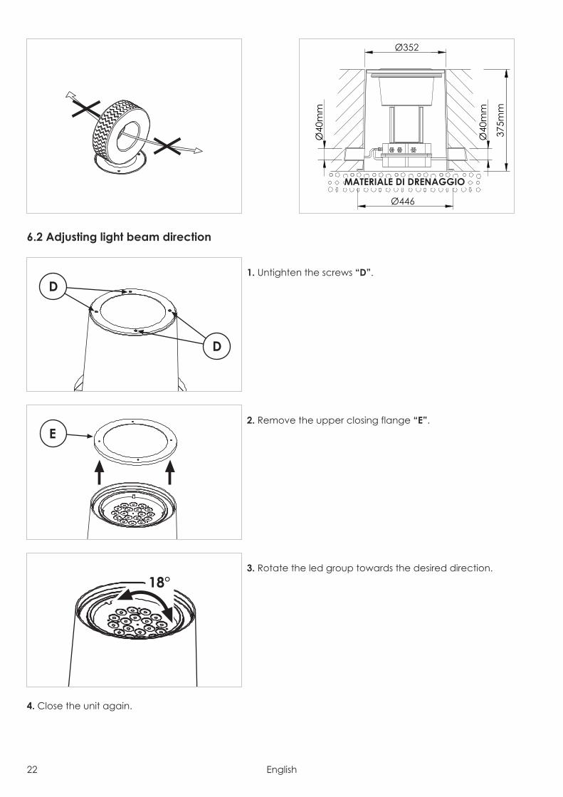
6.2 Adjusting light beam direction
1. Untighten the screws “D”.
2. Remove the upper closing flange “E”.
3. Rotate the led group towards the desired direction.
4. Close the unit again.
18°
E
D
D
Ø446
Ø352
Ø40
mm
Ø40
mm
375m
m
MATERIALE DI DRENAGGIO
22 English
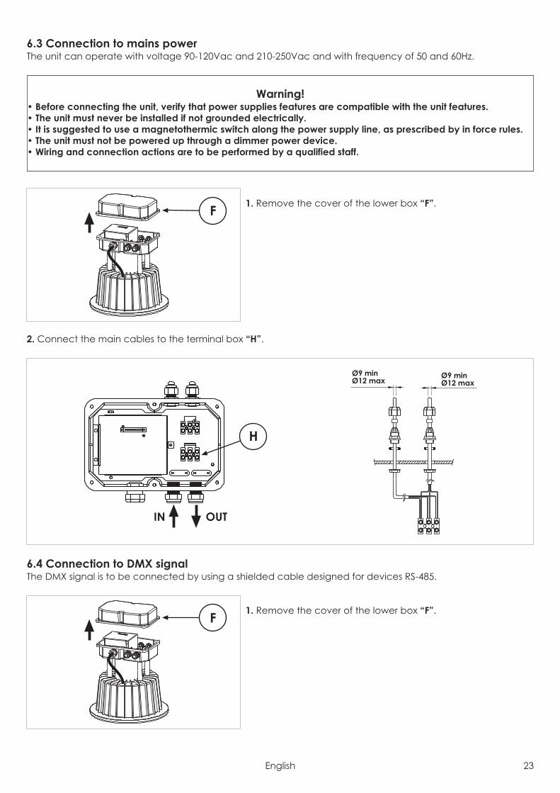
6.3 Connection to mains powerThe unit can operate with voltage 90-120Vac and 210-250Vac and with frequency of 50 and 60Hz.
1. Remove the cover of the lower box “F”.
2. Connect the main cables to the terminal box “H”.
6.4 Connection to DMX signalThe DMX signal is to be connected by using a shielded cable designed for devices RS-485.
1. Remove the cover of the lower box “F”.F
IN OUT
H
Ø9 minØ12 max
Ø9 minØ12 max
F
Warning!• Before connecting the unit, verify that power supplies features are compatible with the unit features.• The unit must never be installed if not grounded electrically.• It is suggested to use a magnetothermic switch along the power supply line, as prescribed by in force rules.• The unit must not be powered up through a dimmer power device.• Wiring and connection actions are to be performed by a qualified staff.
English 23
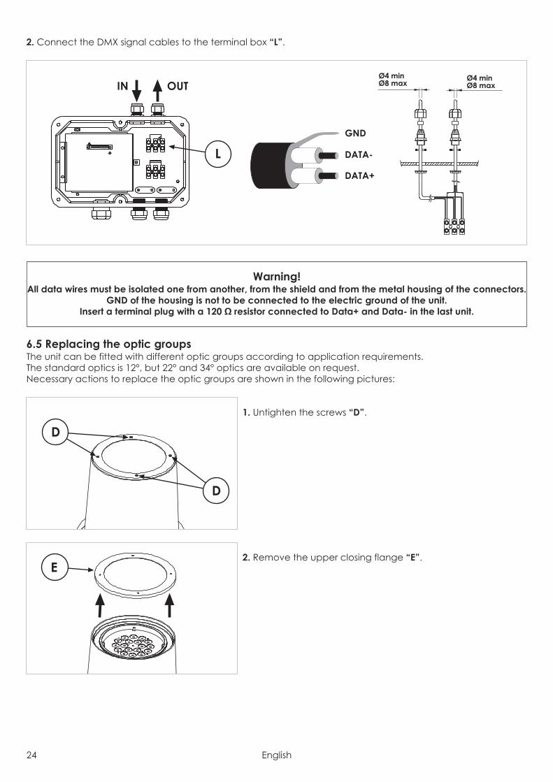
2. Connect the DMX signal cables to the terminal box “L”.
6.5 Replacing the optic groupsThe unit can be fitted with different optic groups according to application requirements.The standard optics is 12°, but 22° and 34° optics are available on request.Necessary actions to replace the optic groups are shown in the following pictures:
1. Untighten the screws “D”.
2. Remove the upper closing flange “E”.E
D
D
Warning!All data wires must be isolated one from another, from the shield and from the metal housing of the connectors.
GND of the housing is not to be connected to the electric ground of the unit.Insert a terminal plug with a 120 Ω resistor connected to Data+ and Data- in the last unit.
IN OUT
GND
DATA-
DATA+
L
Ø4 minØ8 max
Ø4 minØ8 max
24 English
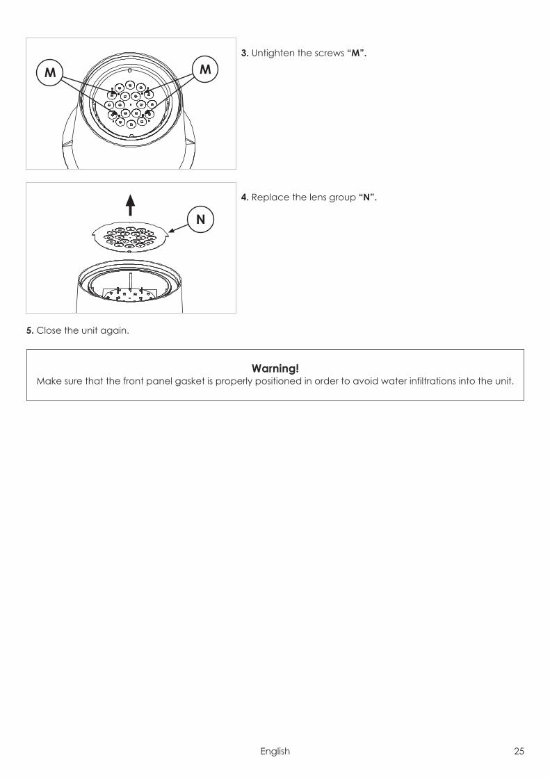
3. Untighten the screws “M”.
4. Replace the lens group “N”.
5. Close the unit again.
Warning!Make sure that the front panel gasket is properly positioned in order to avoid water infiltrations into the unit.
N
M M
English 25

7.1 Setting operating modeBy the dip-switch set it is possible to select one of the following operating modes:• using DMX512 signal control mode
Each fixture is controlled from DMX512 signal control.• MASTER-SLAVE or AUTOMATIC mode
The projector operates independently, without DMX512 signal control.
7.2 Setting DMX address
To access the dip-switch panel “P” it is necessary to remove thecover of the lower box of the unit, as shown in the following pic-ture.Two leds are next to the dip-switch panel to notify the status ofthe unit.The green led will be on if the unit is powered up.In the presence of DMX signal, the red led will be steady on, inthe absence of signal, the red led will be off, while in Mastermode the red led will flash.
The number of DMX channels used by the unit to operate will depend from value of dip-switch n°11, that activethe function 62 PRESET COLOURS.
• Dip-switch 11 = OFF (function 62 PRESET COLOURS not active)Each unit will use 4 DMX channels.
• Dip-switch 11 = ON (function 62 PRESET COLOURS active)Each unit will use 2 DMX channels.
In case of more units operating in normal mode (62 PRESET COLOURS = OFF), the first unit will be set with address001, the second unit with address 005, the third unit with address 009, etc.In case of more units operating in 62 PRESET COLOURS mode, the first unit will be set with address 001, the secondunit with address 003, the third unit with address 005, etc.The number of the DMX address is to be calculated by summing the values corresponding to the activated dip-switches, which are written in the upper side of the dip-switch set (1, 2, 4, 8, 16, etc.).
1 2 3 4 5 6 7 8 9 10 11 12
1 2 4 8 16 32 64 128
256
N.C
.
62Pr
ese
tco
l.
Ma
ste
r ExampleUnit n°2 with address 005
(dip-switch n°1 and 3 = ON)and 62 PRESET COLOURS function actived
1 2 3 4 5 6 7 8 9 10 11 12
1 2 4 8 16 32 64 128
256
N.C
.
62Pr
ese
tco
l.
Ma
ste
r ExampleUnit n°1 with address 001
(dip-switch n°1 = ON)and 62 PRESET COLOURS function not actived
P
7.0 Use of the unit
26 English
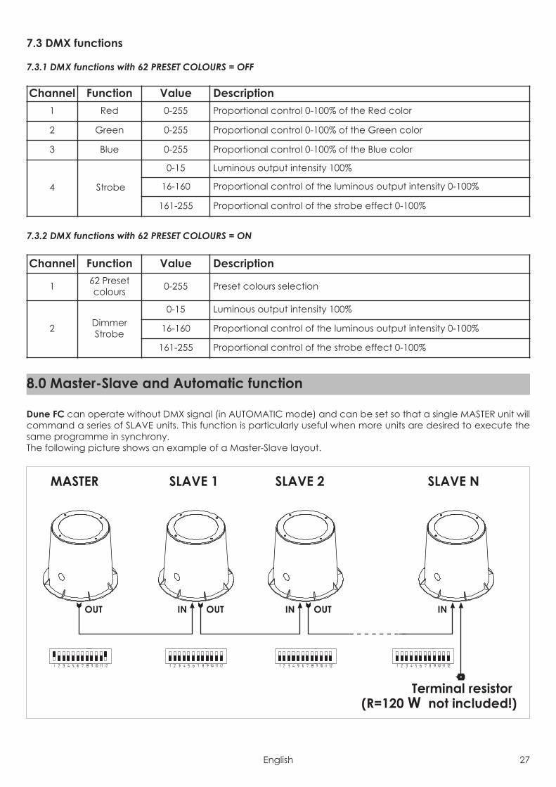
7.3 DMX functions
7.3.1 DMX functions with 62 PRESET COLOURS = OFF
7.3.2 DMX functions with 62 PRESET COLOURS = ON
Dune FC can operate without DMX signal (in AUTOMATIC mode) and can be set so that a single MASTER unit willcommand a series of SLAVE units. This function is particularly useful when more units are desired to execute thesame programme in synchrony.The following picture shows an example of a Master-Slave layout.
MASTER SLAVE 1 SLAVE N
INOUTINOUT
SLAVE 2
INOUT
Terminal resistor(R=120 W not included!)
8.0 Master-Slave and Automatic function
Channel Function Value Description
1 62 Presetcolours 0-255 Preset colours selection
2 DimmerStrobe
0-15 Luminous output intensity 100%
16-160 Proportional control of the luminous output intensity 0-100%
161-255 Proportional control of the strobe effect 0-100%
Channel Function Value Description1 Red 0-255 Proportional control 0-100% of the Red color
2 Green 0-255 Proportional control 0-100% of the Green color
3 Blue 0-255 Proportional control 0-100% of the Blue color
4 Strobe
0-15 Luminous output intensity 100%
16-160 Proportional control of the luminous output intensity 0-100%
161-255 Proportional control of the strobe effect 0-100%
English 27
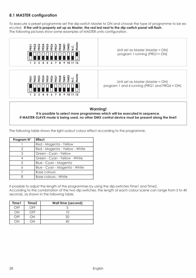
8.1 MASTER configuration
To execute a preset programme set the dip-switch Master to ON and choose the type of programme to be ex-ecuted. If the unit is properly set up as Master, the red led next to the dip-switch panel will flash.The following pictures show some examples of MASTER units configuration.
The following table shows the light output colour effect according to the programme.
It possible to adjust the length of the programmes by using the dip-switches Time1 and Time2.According to the combination of the two dip-switches, the length of each colour scene can range from 5 to 40seconds, as shown in the following table.
Time1 Time2 Wait time (second)OFF OFF 5ON OFF 10OFF ON 20ON ON 40
Program N° Effect1 Red - Magenta - Yellow2 Red - Magenta - Yellow - White3 Green - Cyan - Yellow4 Green - Cyan - Yellow - White5 Blue - Cyan - Magenta6 Blue - Cyan - Magenta - White7 Base colours8 Base colours - White
Warning!It is possible to select more programmes which will be executed in sequence.
If MASTER-SLAVE mode is being used, no other DMX control device must be present along the line!!
1 2 3 4 5 6 7 8 9 10 11 12
PRG
1
PRG
2
PRG
3
PRG
4
PRG
5
PRG
6
PRG
7
PRG
8
TIM
E1
TIM
E2
N.C
.
Ma
ste
r
Unit set as Master (Master = ON)program 1 and 6 running (PRG1 and PRG6 = ON)
1 2 3 4 5 6 7 8 9 10 11 12
PRG
1
PRG
2
PRG
3
PRG
4
PRG
5
PRG
6
PRG
7
PRG
8
TIM
E1
TIM
E2
N.C
.
Ma
ste
r
Unit set as Master (Master = ON)program 1 running (PRG1= ON)
28 English
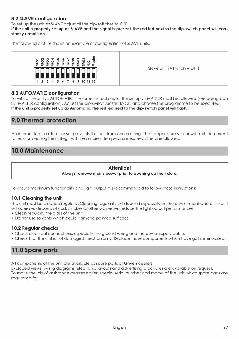
8.2 SLAVE configurationTo set up the unit as SLAVE adjust all the dip-switches to OFF.If the unit is properly set up as SLAVE and the signal is present, the red led next to the dip-switch panel will con-stantly remain on.
The following picture shows an example of configuration of SLAVE units.
8.3 AUTOMATIC configurationTo set up the unit as AUTOMATIC the same instructions for the set up as MASTER must be followed (see paragraph8.1 MASTER configuration). Adjust the dip-switch Master to ON and choose the programme to be executed.If the unit is properly set up as Automatic, the red led next to the dip-switch panel will flash.
An internal temperature sensor prevents the unit from overheating. The temperature sensor will limit the currentto leds, protecting their integrity, if the ambient temperature exceeds the one allowed.
To ensure maximum functionality and light output it is recommended to follow these instructions:
10.1 Cleaning the unitThe unit must be cleaned regularly. Cleaning regularity will depend especially on the environment where the unitwill operate: deposits of dust, smokes or other wastes will reduce the light output performances.• Clean regularly the glass of the unit.• Do not use solvents which could damage painted surfaces.
10.2 Regular checks• Check electrical connections, especially the ground wiring and the power supply cable.• Check that the unit is not damaged mechanically. Replace those components which have got deteriorated.
All components of the unit are available as spare parts at Griven dealers.Exploded views, wiring diagrams, electronic layouts and advertising brochures are available on request.To make the job of assistance centres easier, specify serial number and model of the unit which spare parts arerequested for.
11.0 Spare parts
Attention!Always remove mains power prior to opening up the fixture.
10.0 Maintenance
9.0 Thermal protection
1 2 3 4 5 6 7 8 9 10 11 12
PRG
1
PRG
2
PRG
3
PRG
4
PRG
5
PRG
6
PRG
7
PRG
8
TIM
E1
TIM
E2
N.C
.
Ma
ste
r
Slave unit (All witch = OFF)
English 29
The European Directive 2002/96/EC on Waste Electrical and Electronic Equipment (WEEE), requires that oldlighting fixtures must not be disposed of the normal unsorted municipal waste stream. Old appliances must becollected separately in order to optimise the recovery and recycling of the materials they contain and reducethe impact on human health and the environment.
The crossed out “wheeled bin” symbol on the product reminds you of your obligation, thatwhen you dispose of the appliance it the must be separately collected.
Consumer should contact their local authority or retailer for information concerning the correct disposal of theirold appliance.
13.0 Disposal
Inconvenience Possibile Cause ActionThe led next to thedip-switch set will notturn on.
Unit not powered up. Check that the power supply cable is connected and theunit is powered.
Out of order PCB Check the PCB functions.
The unit does notrespond properlyto the DMX control.
Incorrect DMX cableconnection.
Check connections and wires. Rectify inefficient connec-tions. Repair or replace damaged wires.
Unfinished data connection. Insert a terminal resistor in the terminal box of the lastunit of the connection.
Incorrect addressassignment to the units. Check the addresses of the units and the protocol settings.
One of the unit is faulty andit is affecting the datatransmission along theconnection.
Short-circuit units singularly, one by one,since regular working is restored.
The unit is set to Master orAutomatic, but is not run-ning any programs.
In addition to setting theMaster dip-switch to ON, it isnecessary to also select aprogram number.
Select a program number.
The unit is set to Slave,but does notrespond properlyto the Master.
There more than a unit is setto Master.
Check that amongst the interconnected fixtures, only onehas been set to Master.
Conflict in signals. Ensure that there is no incoming DMX signal.
12.0 Troubleshooting
30 English

Mechanical featuresHeight . . . . . . . . . . . . . . . . . . . . . . . . . . . . . . . . . . . . . . . . . . . . . . . . . . . . . . . . . . . . . . . . . . . . . . . . . . . . . . . 382mm (15”)Width . . . . . . . . . . . . . . . . . . . . . . . . . . . . . . . . . . . . . . . . . . . . . . . . . . . . . . . . . . . . . . . . . . . . . . . . . . . . Ø446mm (17.55”)Depth . . . . . . . . . . . . . . . . . . . . . . . . . . . . . . . . . . . . . . . . . . . . . . . . . . . . . . . . . . . . . . . . . . . . . . . . . . . . . Ø347mm (13.7”)Weight . . . . . . . . . . . . . . . . . . . . . . . . . . . . . . . . . . . . . . . . . . . . . . . . . . . . . . . . . . . . . . . . . . . . . . . . . . . . 15.6Kg (34.2Lbs)Thermal featuresMaximum ambient temperature . . . . . . . . . . . . . . . . . . . . . . . . . . . . . . . . . . . . . . . . . . . . . . . . . . . . . . . . . . 40°C (104°F)Maximum surface temperature . . . . . . . . . . . . . . . . . . . . . . . . . . . . . . . . . . . . . . . . . . . . . . . . . . . . . . . <60°C ( <140°F)Electrical featuresVoltage . . . . . . . . . . . . . . . . . . . . . . . . . . . . . . . . . . . . . . . . . . . . . . . . . . . . . . . . . . . . 90-120 Vac / 210-250 Vac 50/60HzNominal current . . . . . . . . . . . . . . . . . . . . . . . . . . . . . . . . . . . . . . . . . . . . . . . . . . . . . . . . . . . 1.2A @ 110V / 0.6A @ 230VMaximum power . . . . . . . . . . . . . . . . . . . . . . . . . . . . . . . . . . . . . . . . . . . . . . . . . . . . . . . . . . . . . . . . . . . . . . . . . . . . . . 75WThermal protection . . . . . . . . . . . . . . . . . . . . . . . . . . . . . . . . . . . . . . . . . . . . . . . . . . . . . . . . . . . . . . . . . . . . . . . ElectronicLight output sourceType of light output source . . . . . . . . . . . . . . . . . . . . . . . . . . . . . . . . . . . . . . . . . . . . . . . . . . . . . . . . . . 18 Leds RGB x 3WOpticsOptical system . . . . . . . . . . . . . . . . . . . . . . . . . . . . . . . . . . . . . . . . . . . . . . . . . . . . . . . . . . . . . . . . . . . . . . . . . . . . . LensesAvailable optics . . . . . . . . . . . . . . . . . . . . . . . . . . . . . . . . . . . . . . . . 12° cod.AL1760 / 28° cod.1762 / 40° cod.AL1764ControlProtocol . . . . . . . . . . . . . . . . . . . . . . . . . . . . . . . . . . . . . . . . . . . . . . . . . . . . . . . . . . . . . . . . . . . . . . . . . . . . . USITT DMX-512Control channel . . . . . . . . . . . . . . . . . . . . . . 4 channels in standard mode / 2 channels in 62 Preset Colours modeConstructionUnit body . . . . . . . . . . . . . . . . . . . . . . . . . . . . . . . . . . . . . . . . . . . . . . . . . . . . . . . . . . . . . . . . . . . . . . . . . . . Iron/AluminiumTreatment . . . . . . . . . . . . . . . . . . . . . . . . . . . . . . . . . . . . . . . . . . . . . . . . . . . . . . . . . . . . . . . Scratch resistant black paintWeather protection rate . . . . . . . . . . . . . . . . . . . . . . . . . . . . . . . . . . . . . . . . . . . . . . . . . . . . . . . . . . . . . . . . . . . . . . . IP67
14.0 Technical specifications
English 31

Via Bulgaria, 16 - 46042 CASTEL GOFFREDO (MN) - ItalyTelefono 0376/779483 - Fax 0376/779682 - 0376/779552http://www.griven.com/ e-mail [email protected]
http://www.griven.it/ e-mail [email protected]
User’s manual rel. 3.00