Manuale di installazione, uso e manutenzione, stufe … La stufa è un apparecchio per riscaldare;...
70
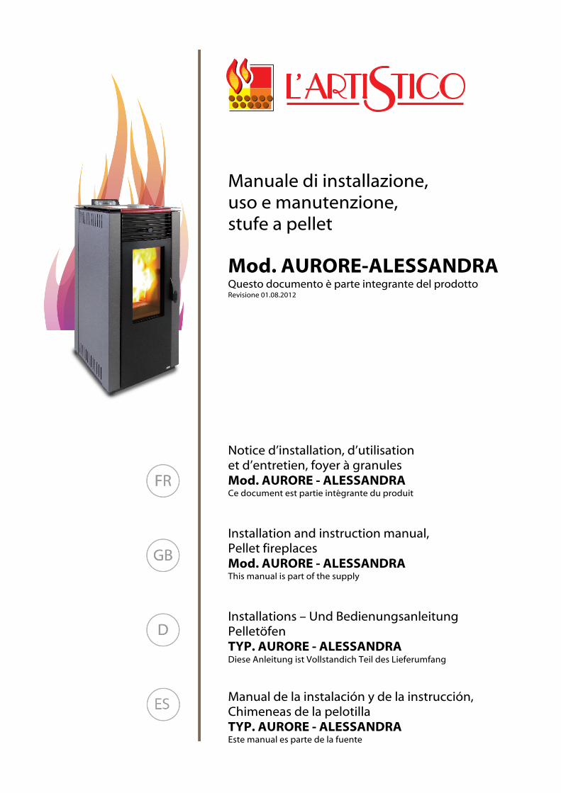
Manuale di installazione, uso e manutenzione, stufe a pellet Mod. AURORE-ALESSANDRA Questo documento è parte integrante del prodotto Revisione 01.08.2012 Notice d’installation, d’utilisation et d’entretien, foyer à granules Mod. AURORE - ALESSANDRA Ce document est partie intégrante du produit Installation and instruction manual, Pellet fireplaces Mod. AURORE - ALESSANDRA This manual is part of the supply Installations – Und Bedienungsanleitung Pelletöfen TYP. AURORE - ALESSANDRA Diese Anleitung ist Vollstandich Teil des Lieferumfang Manual de la instalación y de la instrucción, Chimeneas de la pelotilla TYP. AURORE - ALESSANDRA Este manual es parte de la fuente
Transcript of Manuale di installazione, uso e manutenzione, stufe … La stufa è un apparecchio per riscaldare;...
Manuale di installazione, uso e manutenzione,
stufe a pellet Mod. AURORE-ALESSANDRA Questo documento è parte integrante del prodotto Revisione 01.08.2012
Notice d’installation, d’utilisation et d’entretien, foyer à granules Mod. AURORE - ALESSANDRA Ce document est partie intégrante du produit
Installation and instruction manual, Pellet fireplaces Mod. AURORE - ALESSANDRA This manual is part of the supply
Installations – Und Bedienungsanleitung Pelletöfen TYP. AURORE - ALESSANDRA Diese Anleitung ist Vollstandich Teil des Lieferumfang
Manual de la instalación y de la instrucción, Chimeneas de la pelotilla TYP. AURORE - ALESSANDRA Este manual es parte de la fuente
Leggere attentamente le precauzioni ed eseguire correttamente le procedure.
ATTENZIONE !Non tentare di installare da se la stufa;rivolgersi sempre a personale autorizzato ed addestrato
- In caso di guasto o mal funzionamento rivolgersi sempre al Centro Assitenza Autorizzato;qualsiasi tentativo di rimozione di parti, o di manutenzione dell’apparecchio può esporre l’utente al peri-colo di scosse elettriche. La stufa contiene parti la cui manutenzione deve essere fatta dal CentroAssitenza Autorizzato.
- La stufa è un apparecchio per riscaldare; le sue parti raggiungono alte temperature ed il contattosenza adeguate precauzioni può provocare scottature ed ustioni di grave entità. Far particolarmenteattenzione ai bambini.
- In caso di trasloco, rivolgersi al Centro Assistenza Autorizzato alla rimozione e alla nuova installazione.- Non inserire le dita o oggetti nelle feritoie di uscita del flusso d’aria.All’interno dell’apparecchio vi è un ventilatore che gira ad alta velocità, che potrebbe causare gravi lesio-ni personali. Far particolarmente attenzione ai bambini.
- Non rimanere direttamente esposti al flusso d’aria calda per lunghi periodi di tempo.L’esposizione diretta e prolungata all’aria calda può essere nociva alla salute.Far particolarmente attenzione nelle stanze dove vi siano bambini, persone anziane o persone ammalate.
- In caso di mal funzionamento della stufa arrestare immediatamente il funzionamento dell’appa-recchio, sganciare l’interruttore automatico dedicato e rivolgersi al Centro Assitenza Autorizzato.L’uso continuato dell’apparecchio in tali condizioni può essere all’origine di incendi o folgorazioni.
AVVERTENZE !
- Durante le operazioni di installazione della stufa, evitare l’accesso ai bambini sul luogo di lavoro.Possono verificarsi incidenti imprevisti.
- Non bloccare o coprire in alcun modo il corpo della stufa o occludere le feritoie poste sul latosuperiore.L’ostruzione di tali feritoie è causa di incendi.
- Non usare la stufa in ambienti contenenti, apparecchi di precisione, opere d’arte.La qualità degli oggetti conservati potrebbe subire un deterioramento.
- Non esporre animali o piante al diretto flusso d’aria dell’apparecchio.Una lunga esposizione diretta al flusso d’aria della stufa può avere influenze negative su piante ed ani-mali.
- Aerare di tanto in tanto la stanza nel corso dell’utilizzo dell’apparecchio.Un areazione insufficiente può essere all’origine di insufficienza di ossigeno nella stanza.
- Non esporre la stufa a contatto con l’acqua.L’isolamento elettrico potrebbe subire danni, con conseguenti possibili folgorazioni e rotture per lo sbal-zo termico.
- Verificare le condizioni di installazione per individuare eventuali danni.- Non usare gas infiammabili nelle vicinanze della stufa.- Sganciare l’interruttore automatico se si prevede di non utilizzare l’apparecchio per lunghi periodi ditempo.
- A tutte le nostre stufe viene provata l’accensione in linea.
12
Normative e dichiarazione di conformità
Legislazione• La nostra azienda dichiara che la stufa èconforme alle seguenti norme per la marca-tura CE Direttiva Europea.• 2006/42 CE (direttiva macchine)• 89/336 CEE e 2004/108 CE (direttiva EMC)e sucessivi emendamenti.• 2006/95 CE (direttiva bassa tensione) esucessivi emendamenti.• 89/106 CE (prodotti da costruzione).• Per l’installazione in Italia fare riferimentoalla UNI 10683/98 o successive modifiche eper l’impianto idrotermosanitario farsi rila-sciare da chi ha eseguito l’impianto ladichiarazione di conformità secondo L.37/2008. Tutte le leggi locali e nazionali e lenorme europee devono essere soddisfattenell’installazione dell’apparecchio.
• EN 60335-1 - EN 50165 - EN 50366 - EN55014-1 - EN 61000-3-2 - EN 61000-3-3 -EN 14785.
ResponsabilitàIl costruttore declina ogni responsabilità civileo penale diretta o indiretta dovuta a:• Scarsa manutenzione.• Inosservanza delle istruzioni contenute neimanuali.
• Uso non conforme alle direttive di sicurezza.• Installazione non conforme alle normativevigenti nel paese.
• Installazione da parte del personale nonqualificato e non addestrato.
• Modifiche e riparazioni non autorizzate dalcostruttore.
• Utilizzo di ricambi non originali.• Eventi eccezionali.• Uso di pellet non approvato dal costruttore.
InstallazioneCanna fumariaLa canna fumaria dovrà rispondere ai seguen-ti requisiti:• Non dovrà essere collegato nessun altrocaminetto, stufa, caldaia, o cappa aspiran-te di nessun tipo (fig.1).
• Deve essere adeguatamente distanziata damateriali combustibili o infiammabili median-te intercapedine d’aria o opportuno isolante.
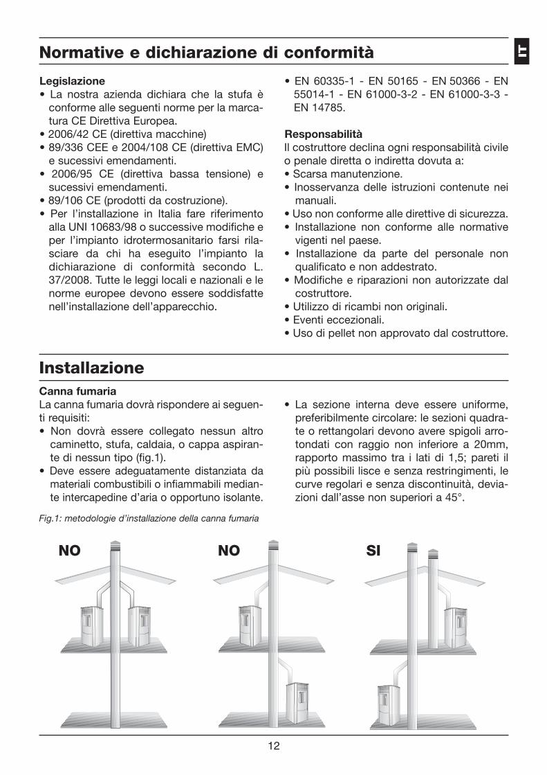
• La sezione interna deve essere uniforme,preferibilmente circolare: le sezioni quadra-te o rettangolari devono avere spigoli arro-tondati con raggio non inferiore a 20mm,rapporto massimo tra i lati di 1,5; pareti ilpiù possibili lisce e senza restringimenti, lecurve regolari e senza discontinuità, devia-zioni dall’asse non superiori a 45°.
NO NO SI
Fig.1: metodologie d’installazione della canna fumariaIT
13
Installazione
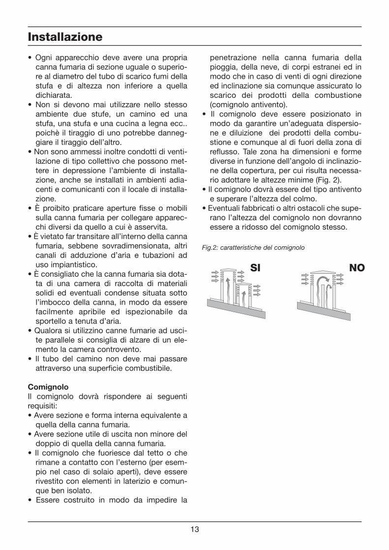
NOSI
Fig.2: caratteristiche del comignolo
• Ogni apparecchio deve avere una propriacanna fumaria di sezione uguale o superio-re al diametro del tubo di scarico fumi dellastufa e di altezza non inferiore a quelladichiarata.
• Non si devono mai utilizzare nello stessoambiente due stufe, un camino ed unastufa, una stufa e una cucina a legna ecc..poichè il tiraggio di uno potrebbe danneg-giare il tiraggio dell’altro.
• Non sono ammessi inoltre condotti di venti-lazione di tipo collettivo che possono met-tere in depressione l’ambiente di installa-zione, anche se installati in ambienti adia-centi e comunicanti con il locale di installa-zione.
• È proibito praticare aperture fisse o mobilisulla canna fumaria per collegare apparec-chi diversi da quello a cui è asservita.
• È vietato far transitare all’interno della cannafumaria, sebbene sovradimensionata, altricanali di adduzione d’aria e tubazioni aduso impiantistico.
• È consigliato che la canna fumaria sia dota-ta di una camera di raccolta di materialisolidi ed eventuali condense situata sottol’imbocco della canna, in modo da esserefacilmente apribile ed ispezionabile dasportello a tenuta d’aria.
• Qualora si utilizzino canne fumarie ad usci-te parallele si consiglia di alzare di un ele-mento la camera controvento.
• Il tubo del camino non deve mai passareattraverso una superficie combustibile.
ComignoloIl comignolo dovrà rispondere ai seguentirequisiti:• Avere sezione e forma interna equivalente aquella della canna fumaria.
• Avere sezione utile di uscita non minore deldoppio di quella della canna fumaria.
• Il comignolo che fuoriesce dal tetto o cherimane a contatto con l’esterno (per esem-pio nel caso di solaio aperti), deve essererivestito con elementi in laterizio e comun-que ben isolato.
• Essere costruito in modo da impedire la
penetrazione nella canna fumaria dellapioggia, della neve, di corpi estranei ed inmodo che in caso di venti di ogni direzioneed inclinazione sia comunque assicurato loscarico dei prodotti della combustione(comignolo antivento).
• Il comignolo deve essere posizionato inmodo da garantire un’adeguata dispersio-ne e diluizione dei prodotti della combu-stione e comunque al di fuori della zona direflusso. Tale zona ha dimensioni e formediverse in funzione dell’angolo di inclinazio-ne della copertura, per cui risulta necessa-rio adottare le altezze minime (Fig. 2).
• Il comignolo dovrà essere del tipo antiventoe superare l’altezza del colmo.
• Eventuali fabbricati o altri ostacoli che supe-rano l’altezza del comignolo non dovrannoessere a ridosso del comignolo stesso.
14
Dimensionamenti
Il locale adiacente non può essere adibi-to ad autorimessa, magazzino di mate-riale combustibile nè comunque ad atti-vità con pericolo d’incendio.
Secondo la norma UNI 10683/98, la stufa nondeve essere nello stesso ambiente in cui sitrovano estrattori, apparecchi a gas di tipo Be comunque dispositivi che mettano il localein depressione.
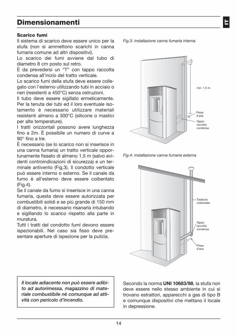
Scarico fumiIl sistema di scarico deve essere unico per lastufa (non si ammettono scarichi in cannafumaria comune ad altri dispositivi).Lo scarico dei fumi avviene dal tubo didiametro 8 cm posto sul retro.È da prevedersi un “T” con tappo raccoltacondensa all’inizio del tratto verticale.Lo scarico fumi della stufa deve essere colle-gato con l’esterno utilizzando tubi in acciaio oneri (resistenti a 450°C) senza ostruzioni.Il tubo deve essere sigillato ermeticamente.Per la tenuta dei tubi ed il loro eventuale iso-lamento è necessario utilizzare materialiresistenti almeno a 300°C (silicone o masticiper alte temperature).I tratti orizzontali possono avere lunghezzafino a 2m. È possibile un numero di curve a90° fino a tre.È necessario (se lo scarico non si inserisce inuna canna fumaria) un tratto verticale oppor-tunamente fissato di almeno 1,5 m (salvo evi-denti controindicazioni di sicurezza) e un ter-minale antivento (Fig.3). Il condotto verticalepuò essere interno o esterno. Se il canale dafumo è all’esterno deve essere coibentato(Fig.4).Se il canale da fumo si inserisce in una cannafumaria, questa deve essere autorizzata percombustibili solidi e se più grande di 150 mmdi diametro, è necessario risanarla intubandoe sigillando lo scarico rispetto alla parte inmuratura.Tutti i tratti del condotto fumi devono essereispezionabili. Nel caso sia fisso deve pre-sentare aperture di ispezione per la pulizia.
Presad’aria
Tapporaccoltacondensa
min. 1,5 m.
Presad’aria
Tapporaccoltacondensa
Fig.3: installazione canna fumaria interna
Fig.4: installazione canna fumaria esterna
Tubaturacoibentata
IT

15
Dimensionamenti
Presa d’aria esterna
La stufa deve poter disporre dell’aria necessa-ria a garantire il regolare funzionamento dellacombustione e un buon benessere ambientale.• Assicurarsi che nella stanza in cui è installa-ta la stufa ci sia un’areazione sufficiente e,se necessario, installare un condotto diadduzione d’aria dall’esterno di diametrominimo consigliato di 50 mm.
• La presa d’aria esterna deve comunicarecon la stufa e posizionata in modo da evita-re che possa essere ostruita. Deve essereprotetta con una griglia permanente nonrichiudibile o idonea protezione purchè nonvenga ridotta la sezione minima.
• L’afflusso d’aria può essere ottenuto ancheda un locale adiacente a quello di installa-zione purchè tale flusso possa avvenire libe-ramente attraverso aperture permanenti nonrichiudibili comunicanti con l’esterno.
• Il locale adiacente rispetto a quello di instal-lazione non deve essere messo in depres-sione rispetto all’ambiente esterno per effet-to del tiraggio contrario provocato dalla pre-senza in tale locale di altro apparecchio diutilizzazione o di dispositivo di aspirazione.
• Nel locale adiacente le aperture permanentidevono rispondere ai requisiti di cui ai puntisopra.
Dimensioni termostufa a pellet
Dimensionamenti
������
����
���
����
���
���
����
���
��
������
��
���
���
������
����
���������
�����
���
�����
Ø 50mm Ø 80mm
Entrata ariacomburente Scarico fumi
entrata acqua uscita acqua
Dimensioni approssimative (mm).
16
La stufa è fornita di un cavo di alimentazioneelettrica da collegarsi a una presa di 230V50Hz, preferibilmente con interruttore magne-totermico. Variazioni di tensione superiori al10% possono compromettere la stufa (se nongià esistente si preveda un interruttore dif-ferenziale adeguato).L’impianto elettrico deve essere a norma; ver-ificare in particolare l’efficienza del circuito dimessa a terra. La linea di alimentazione deveessere di sezione adeguata alla potenza del-l’apparecchiatura.La stufa deve essere posizionata in bolla.Verificare la capacità portante del pavimento.Il posizionamento della stufa all’interno del-l’ambiente abitativo è determinante per riu-scire a scaldare in maniera uniforme l’ambientestesso. Prima di decidere dove collocare lastufa, bisogna tener presente che:• L’aria di combustione non si può ottenereda una autorimessa o da uno spazio senzaventilazione o ricambio d’aria, ma da unospazio libero o esterno;
• È sconsigliata l’installazione in una camerada letto;
• È preferibile invece l’installazione in unastanza grande e centrale della casa perassicurare la massima circolazione delcalore;
Posizionamenti
40 cm.
20 cm.20 cm.
40 cm.
40 cm.20 cm.
40 cm.
80 cm.
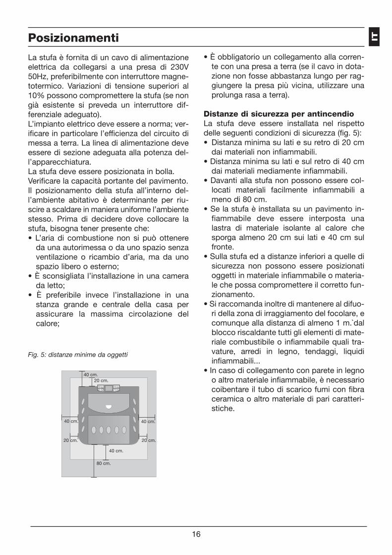
Fig. 5: distanze minime da oggetti
• È obbligatorio un collegamento alla corren-te con una presa a terra (se il cavo in dota-zione non fosse abbastanza lungo per rag-giungere la presa più vicina, utilizzare unaprolunga rasa a terra).
Distanze di sicurezza per antincendioLa stufa deve essere installata nel rispettodelle seguenti condizioni di sicurezza (fig. 5):• Distanza minima su lati e su retro di 20 cmdai materiali non infiammabili.
• Distanza minima su lati e sul retro di 40 cmdai materiali mediamente infiammabili.
• Davanti alla stufa non possono essere col-locati materiali facilmente infiammabili ameno di 80 cm.
• Se la stufa è installata su un pavimento in-fiammabile deve essere interposta unalastra di materiale isolante al calore chesporga almeno 20 cm sui lati e 40 cm sulfronte.
• Sulla stufa ed a distanze inferiori a quelle disicurezza non possono essere posizionatioggetti in materiale infiammabile o materia-le che possa compromettere il corretto fun-zionamento.
• Si raccomanda inoltre di mantenere al difuo-ri della zona di irraggiamento del focolare, ecomunque alla distanza di almeno 1 m.`dalblocco riscaldante tutti gli elementi di mate-riale combustibile o infiammabile quali tra-vature, arredi in legno, tendaggi, liquidiinfiammabili...
• In caso di collegamento con parete in legnoo altro materiale infiammabile, è necessariocoibentare il tubo di scarico fumi con fibraceramica o altro materiale di pari caratteri-stiche.
IT

17
Posizionamenti
Fig. 6: distanze dai muri
Montaggio e accensione
NOTA RELATIVA ALLA MAIOLICA (ovepresente): il rivestimento della stufa èrealizzato in maiolica semirefrattaria(da non confondere però con altrimateriali come per esempio la porcel-lana). Il cavillo e i puntini o vulcanid’aria sono caratteristiche di talemaiolica fatta a mano, e quindi nonsono da considerarsi difetti e noninfluiscono minimamente sulla duratadel prodotto.
Attenzione: maneggiare con cura.
FRAGILE!
ATTENZIONE:Assicurarsi che il cestello del bracieresia posizionato nella maniera corretta.
• Togliere dall’interno del serbatoio tutti ipezzi che sono stati inseriti nel momento del-l’imballo.• Srotolare la sonda ambiente posta sul retro
della stufa, non facendola appoggiare su partisoggette al riscaldamento termico.• Collegare correttamente la stufa a pellet allacanna fumaria, alla presa d’aria e alletubazioni dell’acqua.• Inserire la presa alla corrente e procederealla accensione seguendo le fasi descritte nelmanuale d’istruzioni.• Posizionare la parte superiore e relativi col-legamenti elettrici del quadro comandi allascheda elettronica attraverso le ferritoie pre-disposte sul retro.
Si prega di leggere attentamente (e spiegareal cliente) le avvertenze riportate nel manualed’uso e manutenzione prima di installare emettere in funzione la stufa!
Subito dopo l’accensione della stufa verifi-care alla voce UT04 sul display della stufal’impostazione dei parametri tecnici (vedimanuale riservato agli installatori).
1. PRIMA ACCENSIONE A CURA DELTECNICO AUTORIZZATO
20 cm.
20 cm.
Pareti
entrata ariacomburente
Areazione minima per presa d’aria com-burente
E’ obbligatorio prelevare l’aria per la com-bustione direttamente dall’esterno.
Per un posizionamento corretto e sicuro dellapresa d’aria si devono rispettare delle misuree delle prescrizioni (Fig. 6). Sono distanze darispettare per evitare che l’aria comburentepossa essere sottratta da un’altra fonte: peresempio l’apertura di una finestra può risuc-chiare l’aria esterna facendola mancare allastufa.
18
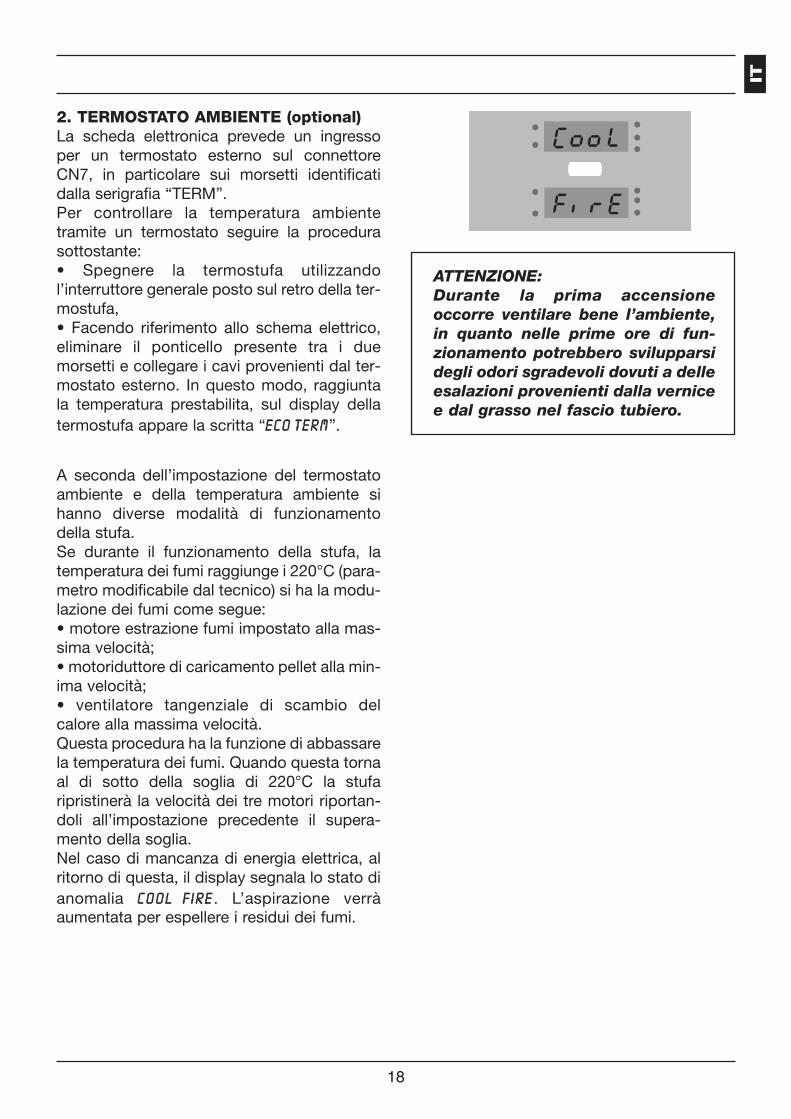
2. TERMOSTATO AMBIENTE (optional)La scheda elettronica prevede un ingressoper un termostato esterno sul connettoreCN7, in particolare sui morsetti identificatidalla serigrafia “TERM”.Per controllare la temperatura ambientetramite un termostato seguire la procedurasottostante:• Spegnere la termostufa utilizzandol’interruttore generale posto sul retro della ter-mostufa,• Facendo riferimento allo schema elettrico,eliminare il ponticello presente tra i duemorsetti e collegare i cavi provenienti dal ter-mostato esterno. In questo modo, raggiuntala temperatura prestabilita, sul display dellatermostufa appare la scritta “EE CC OO TT EE RR MM”.
A seconda dell’impostazione del termostatoambiente e della temperatura ambiente sihanno diverse modalità di funzionamentodella stufa.Se durante il funzionamento della stufa, latemperatura dei fumi raggiunge i 220°C (para-metro modificabile dal tecnico) si ha la modu-lazione dei fumi come segue:• motore estrazione fumi impostato alla mas-sima velocità;• motoriduttore di caricamento pellet alla min-ima velocità;• ventilatore tangenziale di scambio delcalore alla massima velocità.Questa procedura ha la funzione di abbassarela temperatura dei fumi. Quando questa tornaal di sotto della soglia di 220°C la stufaripristinerà la velocità dei tre motori riportan-doli all’impostazione precedente il supera-mento della soglia.Nel caso di mancanza di energia elettrica, alritorno di questa, il display segnala lo stato dianomalia CC OO OO LL FF II RR EE . L’aspirazione verràaumentata per espellere i residui dei fumi.
ATTENZIONE: Durante la prima accensioneoccorre ventilare bene l’ambiente,in quanto nelle prime ore di fun-zionamento potrebbero svilupparsidegli odori sgradevoli dovuti a delleesalazioni provenienti dalla vernicee dal grasso nel fascio tubiero.
IT
Manutenzione a cura del C.A.A.
Operazioni da eseguire ogni stagioneprima dell’accensione a cura del CentroAssistenza Autorizzato• Pulizia generale interna ed esterna.• Pulizia accurata dei tubi di scambio.• Pulizia accurata e disincrostazione del cro-giolo e del relativo vano.
• Pulizia motori, verifica meccanica dei giochie dei fissaggi.
• Pulizia canale da fumo (sostituzione delleguarnizioni sui tubi) e del vano ventilatoreestrazione fumi.
• Pulizia pressostato, sostituzione tubicino insilicone.
• Controllo sonde.
19
• Sostituzione della pila dell’orologio sullascheda elettronica.
• Pulizia, ispezione e disincrostazione delvano della resistenza di accensione, sosti-tuzione della stessa se necessario.
• Pulizia/controllo del pannello sinottico• Ispezione visiva dei cavi elettrici, delle con-nessioni e del cavo di alimentazione
• Pulizia serbatoio pellet e verifica giochiassieme coclea-motoriduttore
• Sostituzione della guarnizione portello• Collaudo funzionale, caricamento coclea,accensione, funzionamento per 10 minuti espegnimento.
• Controllo della parte elettrica e dei compo-nenti elettronici.
i
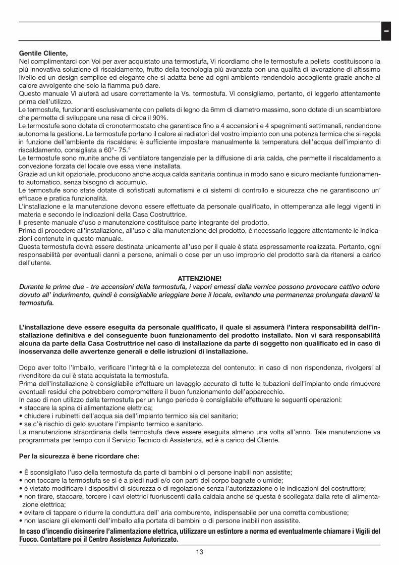
Gentile Cliente,Nel complimentarci con Voi per aver acquistato una termostufa, Vi ricordiamo che le termostufe a pellets costituiscono la più innovativa soluzione di riscaldamento, frutto della tecnologia più avanzata con una qualità di lavorazione di altissimo livello ed un design semplice ed elegante che si adatta bene ad ogni ambiente rendendolo accogliente grazie anche al calore avvolgente che solo la fiamma può dare.Questo manuale Vi aiuterà ad usare correttamente la Vs. termostufa. Vi consigliamo, pertanto, di leggerlo attentamente prima dell’utilizzo.Le termostufe, funzionanti esclusivamente con pellets di legno da 6mm di diametro massimo, sono dotate di un scambiatore che permette di sviluppare una resa di circa il 90%.Le termostufe sono dotate di cronotermostato che garantisce fino a 4 accensioni e 4 spegnimenti settimanali, rendendone autonoma la gestione. Le termostufe portano il calore ai radiatori del vostro impianto con una potenza termica che si regola in funzione dell’ambiente da riscaldare: è sufficiente impostare manualmente la temperatura dell’acqua dell’impianto di riscaldamento, consigliata a 60°- 75.°Le termostufe sono munite anche di ventilatore tangenziale per la diffusione di aria calda, che permette il riscaldamento a convezione forzata del locale ove essa viene installata. Grazie ad un kit opzionale, producono anche acqua calda sanitaria continua in modo sano e sicuro mediante funzionamen-to automatico, senza bisogno di accumulo.Le termostufe sono state dotate di sofisticati automatismi e di sistemi di controllo e sicurezza che ne garantiscono un’ efficace e pratica funzionalità. L’installazione e la manutenzione devono essere effettuate da personale qualificato, in ottemperanza alle leggi vigenti in materia e secondo le indicazioni della Casa Costruttrice.Il presente manuale d’uso e manutenzione costituisce parte integrante del prodotto.Prima di procedere all’installazione, all’uso e alla manutenzione del prodotto, è necessario leggere attentamente le indica-zioni contenute in questo manuale.Questa termostufa dovrà essere destinata unicamente all’uso per il quale è stata espressamente realizzata. Pertanto, ogni responsabilità per eventuali danni a persone, animali o cose per un uso improprio del prodotto sarà da ritenersi a carico dell’utente.
L’installazione deve essere eseguita da personale qualificato, il quale si assumerà l’intera responsabilità dell’in-stallazione definitiva e del conseguente buon funzionamento del prodotto installato. Non vi sarà responsabilità alcuna da parte della Casa Costruttrice nel caso di installazione da parte di soggetto non qualificato ed in caso di inosservanza delle avvertenze generali e delle istruzioni di installazione.
Dopo aver tolto l’imballo, verificare l’integrità e la completezza del contenuto; in caso di non rispondenza, rivolgersi al rivenditore da cui è stata acquistata la termostufa.Prima dell’installazione è consigliabile effettuare un lavaggio accurato di tutte le tubazioni dell’impianto onde rimuovere eventuali residui che potrebbero compromettere il buon funzionamento dell’apparecchio.In caso di non utilizzo della termostufa per un lungo periodo è consigliabile effettuare le seguenti operazioni: • staccare la spina di alimentazione elettrica; • chiudere i rubinetti dell’acqua sia dell’impianto termico sia del sanitario;• se c’è rischio di gelo svuotare l’impianto termico e sanitario.La manutenzione straordinaria della termostufa deve essere eseguita almeno una volta all’anno. Tale manutenzione va programmata per tempo con il Servizio Tecnico di Assistenza, ed è a carico del Cliente.
Per la sicurezza è bene ricordare che:
• È sconsigliato l’uso della termostufa da parte di bambini o di persone inabili non assistite;• non toccare la termostufa se si è a piedi nudi e/o con parti del corpo bagnate o umide;• é vietato modificare i dispositivi di sicurezza o di regolazione senza l’autorizzazione o le indicazioni del costruttore;• non tirare, staccare, torcere i cavi elettrici fuoriuscenti dalla caldaia anche se questa è scollegata dalla rete di alimenta-zione elettrica;
• evitare di tappare o ridurre la conduttura dell’ aria comburente, indispensabile per una corretta combustione;• non lasciare gli elementi dell’imballo alla portata di bambini o di persone inabili non assistite.
13
ATTENZIONE!Durante le prime due - tre accensioni della termostufa, i vapori emessi dalla vernice possono provocare cattivo odore dovuto all’ indurimento, quindi è consigliabile arieggiare bene il locale, evitando una permanenza prolungata davanti la termostufa.
In caso d’incendio disinserire l’alimentazione elettrica, utilizzare un estintore a norma ed eventualmente chiamare i Vigili del Fuoco. Contattare poi il Centro Assistenza Autorizzato.
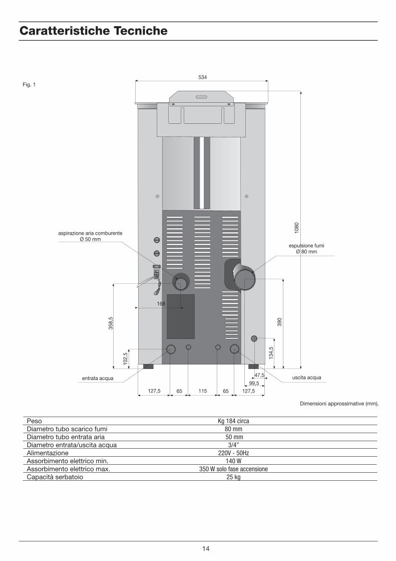
Caratteristiche Tecniche
Kg 184 circa80 mm 50 mm
3/4” 220V - 50Hz
140 W350 W solo fase accensione
25 kg
PesoDiametro tubo scarico fumiDiametro tubo entrata ariaDiametro entrata/uscita acquaAlimentazioneAssorbimento elettrico min.Assorbimento elettrico max.Capacità serbatoio
Fig. 1
14
47,5
99,5127,5 65 115 65 127,5
168
102,
5
358,
5
134,
5
390
1080
534
aspirazione aria comburenteØ 50 mm
espulsione fumiØ 80 mm
uscita acquaentrata acqua
Dimensioni approssimative (mm).
i
AccensionePremere il pulsante per alcuni secondi fino all’avvio della termostufa.
Accensione Termostufa
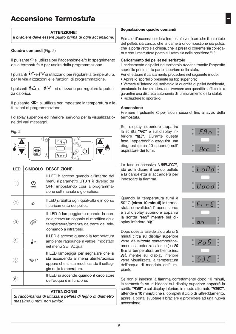
ATTENZIONE! Il braciere deve essere pulito prima di ogni accensione.
Quadro comandi (Fig. 2)
Il pulsante si utilizza per l’accensione e/o lo spegnimento della termostufa e per uscire dalla programmazione.
I pulsanti e si utilizzano per regolare la temperatura, per le visualizzazioni e le funzioni di programmazione.
I pulsanti e si utilizzano per regolare la poten-za calorica.
Il pulsante si utilizza per impostare la temperatura e le funzioni di programmazione.
I display superiore ed inferiore servono per la visualizzazio-ne dei vari messaggi.
Prima dell’accensione della termostufa verificare che il serbatoio del pellets sia carico, che la camera di combustione sia pulita, che la porta vetro sia chiusa, che la presa di corrente sia collega-ta e che l’interruttore posto sul retro sia nella posizione “1”.
Il LED è acceso quando all’interno del menù il parametro UT0 1 è diverso da OFF, impostando così la programma-zione settimanale o giornaliera.
ATTENZIONE!Si raccomanda di utilizzare pellets di legno di diametro massimo 6 mm, non umido.
Sul display superiore apparirà la scritta “Fan” e sul display in-feriore “Acc”. Durante questa fase l’apparecchio eseguirà una diagnosi (circa 20 secondi) sull’ aspiratore dei fumi.
La fase successiva “LOAD WOOD”, sta ad indicare il carico pellets e la candeletta si accenderà per innescare la fiamma.
Quando la temperatura fumi è 50° C (circa 10 minuti) la termo-stufa convaliderà l’ accensione: e sul display superiore apparirà la scritta “FirE” mentre sul di-splay inferiore “ON”.
Dopo questa fase della durata di 5 minuti circa sul display superiore verrà visualizzata contemporane-amente la potenza calorica (es. po 6) e la temperatura ambiente (es. 25°), mentre sul display inferiore verrà visualizzata la temperatura dell’acqua di mandata dell’ im-pianto.
Se non si innesca la fiamma correttamente dopo 10 minuti, la termostufa va in blocco: sul display superiore apparirà la scritta “ALAR” e sul display inferiore in modo alternato “NO ACC”: attendere 10 minuti che si completi il ciclo di raffreddamento, aprire la porta, svuotare il braciere e procedere ad una nuova accensione.
Fig. 2
Segnalazione quadro comandi
15
6
1 2
3
4
5
“SET”
LED SIMBOLO DESCRIZIONE
1
2
3
4
5
6
Il LED si abilita ogni qualvolta è in corso il caricamento del pellet.
Il LED è lampeggiante quando la con-sole riceve un segnale di modifica della temperatura/potenza da parte del tele-comando a infrarossi.
Il LED è acceso quando la temperatura ambiente raggiunge il valore impostato nel menù SET Acqua.
Il LED lampeggia per segnalare che si sta accedendo al menù utente/tecnico oppure che si sta modificando il settag-gio della temperatura.
Il LED si accende quando il circolatore dell’acqua è in funzione.
Caricamento del pellet nel serbatoioIl caricamento delpellet nel serbatoio avviene tramite l’apposito sportello posto nella parte superiore della stufa.Per effettuare il caricamento procedere nel seguente modo:• Aprire lo sportello presente su top superiore;• Versare all’interno del serbatoio la quantità di pellet desiderata, prestando la dovuta attenzione (versare una quantità sufficiente a garantire una discreta autonomia di funzionamento della stufa);• Richiudere lo sportello.
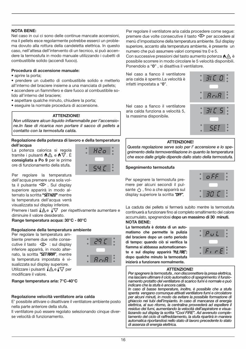
Per spegnere la termostufa pre-mere per alcuni secondi il pul-sante , fino a che apparirà sul display superiore la scritta “OFF”.
NOTA BENE:Nel caso in cui ci sono delle continue mancate accensioni, ma il pellets esce regolarmente potrebbe esserci un proble-ma dovuto alla rottura della candeletta elettrica. In questo caso, nell’attesa dell’intervento di un tecnico, si può accen-dere la termostufa in modo manuale utilizzando i cubetti di combustibile solido (accendi fuoco).
Procedura di accensione manuale:• aprire la porta;• prendere un cubetto di combustibile solido e metterlo all’interno del braciere insieme a una manciata di pellets;• accendere un fiammifero e dare fuoco al combustibile so-lido all’interno del braciere;• aspettare qualche minuto, chiudere la porta;• eseguire la normale procedura di accensione.
Regolazione della potenza di lavoro e della temperatura dell’acqua
Regolazione della temperatura ambiente
Per regolare la temperatura am-biente premere due volte conse-cutive il tasto : sul display inferiore apparirà, in modo alter-nato, la scritta “SET ARIA”, mentre la temperatura impostata è vi-sualizzata sul display superiore.Utilizzare i pulsanti e per modificare il valore.
Premere i tasti e per rispettivamente aumentare e diminuire il valore desiderato.Range temperatura acqua: 30°C - 80°C
ATTENZIONE!Non utilizzare alcun liquido infiammabile per l’accensio-ne.In fase di ricarica non portare il sacco di pellets a contatto con la termostufa calda.
Spegnimento termostufa
La caduta dei pellets si fermerà subito mentre la termostufa continuerà a funzionare fino al completo smaltimento del calore accumulato, spegnendosi dopo un massimo di 30 minuti.
ATTENZIONE!Questa regolazione serve solo per l’ accensione e lo spe-gnimento della termoventilazione in quanto la temperatura che esce dalle griglie dipende dallo stato della termostufa.
La potenza calorica si regola tramite i pulsanti e . É consigliata a Po 9 per le prime ore di funzionamento della stufa.
Per regolare la temperatura dell’acqua premere una sola vol-ta il pulsante
.
. Sul display superiore apparirà in modo al-ternato la scritta “Set H2o” mentre la temperatura dell’acqua verrà visualizzata sul display inferiore.
NOTA BENE:La termostufa è dotata di un auto-matismo che permette la pulizia del braciere dopo un certo periodo di tempo: quando ciò si verifica la fiamma si abbassa automaticamen-te e sul display apparirà “PUL FIRE”; dopo qualche minuto la termostufa inizierà a funzionare normalmente.
16
Range temperatura aria: 7°C-40°C
Regolazione velocità ventilatore aria caldaE’ possibile attivare o disattivare il ventilatore ambiente posto nella parte anteriore della stufa. Il ventilatore può essere regolato selezionando cinque diver-se velocità di funzionamento.
Per regolare il ventilatore aria calda procedere come segue: premere due volte consecutive il tasto per accedere al menù d’impostazione della temperatura ambiente. Sul display superiore, accanto alla temperatura ambiente, è presente un numero che può assumere valori compresi tra 0 e 5. Con successive pressioni del tasto aumento potenza è possibile scorrere in modo circolare le 5 velocità disponibili. Ponendolo a “0” , si disattiva il ventilatore.
Nel caso a fianco il ventilatore aria calda è spento.La velocità è infatti impostata a “0”.
Nel caso a fianco il ventilatore aria calda funziona a velocità 5, la massima disponibile.
ATTENZIONE!Per spegnere la termostufa , non disconnettere la presa elettrica, ma lasciare ultimare il ciclo automatico di spegnimento: il funzio-namento protatto del ventilatore di scarico fumi è normale e può indicare che la stufa è ancora calda. In caso di basse temperature, inoltre, è possibile che a stufa spenta vengano comunque attivati ventilatore fumi e circolatore per alcuni minuti, in modo da evitare la possibile formazione di ghiaccio nei tubi dell’impianto. In caso di mancanza di energia elettrica, al suo ritorno, la centralina provvederà ad espellere il residuo dei fumi, aumentando la velocità dell’aspiratore e visua-lizzando sul display la scritta “Cool FIRE”. Ad avvenuto comple-tamento del ciclo di raffreddamento, la stufa ripartirà in maniera automatica riportandosi nello stato di lavoro precedente lo stato di assenza di energia elettrica.
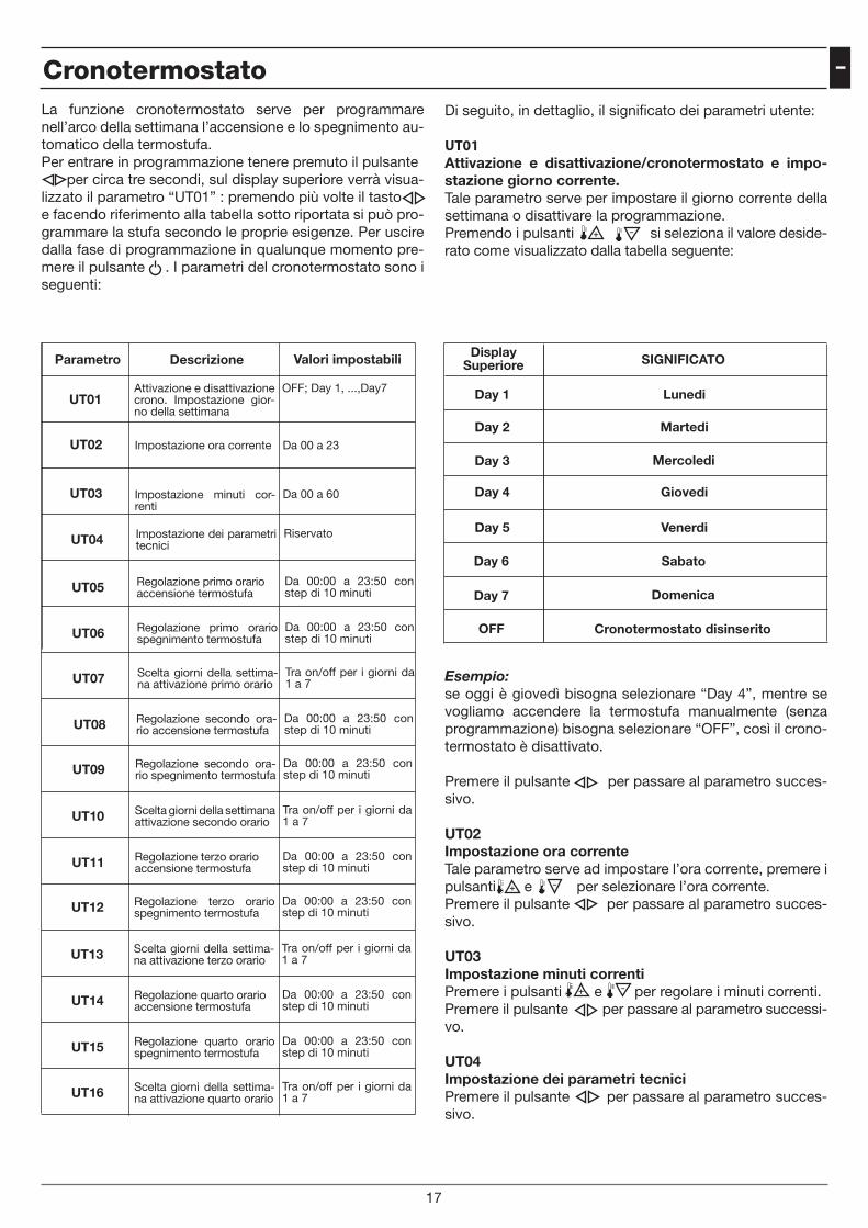
iCronotermostatoLa funzione cronotermostato serve per programmare nell’arco della settimana l’accensione e lo spegnimento au-tomatico della termostufa.Per entrare in programmazione tenere premuto il pulsante per circa tre secondi, sul display superiore verrà visua-lizzato il parametro “UT01” : premendo più volte il tasto e facendo riferimento alla tabella sotto riportata si può pro-grammare la stufa secondo le proprie esigenze. Per uscire dalla fase di programmazione in qualunque momento pre-mere il pulsante . I parametri del cronotermostato sono i seguenti:
Parametro Descrizione Valori impostabili
UT01OFF; Day 1, ...,Day7Attivazione e disattivazione
crono. Impostazione gior-no della settimana
UT02 Da 00 a 23Impostazione ora corrente
UT03 Da 00 a 60Impostazione minuti cor-renti
UT04 RiservatoImpostazione dei parametri tecnici
UT05 Da 00:00 a 23:50 con step di 10 minuti
Regolazione primo orario accensione termostufa
UT06 Da 00:00 a 23:50 con step di 10 minuti
Regolazione primo orario spegnimento termostufa
UT07 Tra on/off per i giorni da 1 a 7
Scelta giorni della settima-na attivazione primo orario
UT08 Da 00:00 a 23:50 con step di 10 minuti
Regolazione secondo ora-rio accensione termostufa
UT09 Da 00:00 a 23:50 con step di 10 minuti
Regolazione secondo ora-rio spegnimento termostufa
UT10 Tra on/off per i giorni da 1 a 7
Scelta giorni della settimana attivazione secondo orario
UT11 Da 00:00 a 23:50 con step di 10 minuti
Regolazione terzo orario accensione termostufa
UT12 Da 00:00 a 23:50 con step di 10 minuti
Regolazione terzo orario spegnimento termostufa
UT13 Tra on/off per i giorni da 1 a 7
Scelta giorni della settima-na attivazione terzo orario
UT14 Da 00:00 a 23:50 con step di 10 minuti
Regolazione quarto orario accensione termostufa
UT15 Da 00:00 a 23:50 con step di 10 minuti
Regolazione quarto orario spegnimento termostufa
UT16 Tra on/off per i giorni da 1 a 7
Scelta giorni della settima-na attivazione quarto orario
Di seguito, in dettaglio, il significato dei parametri utente:
UT01 Attivazione e disattivazione/cronotermostato e impo-stazione giorno corrente.Tale parametro serve per impostare il giorno corrente della settimana o disattivare la programmazione. Premendo i pulsanti si seleziona il valore deside-rato come visualizzato dalla tabella seguente:
DisplaySuperiore SIGNIFICATO
Day 1
Day 2
Day 3
Day 4
Day 5
Day 6
Day 7
OFF
Lunedi
Martedi
Mercoledi
Giovedi
Venerdi
Sabato
Domenica
Cronotermostato disinserito
Esempio: se oggi è giovedì bisogna selezionare “Day 4”, mentre se vogliamo accendere la termostufa manualmente (senza programmazione) bisogna selezionare “OFF”, così il crono-termostato è disattivato.
Premere il pulsante per passare al parametro succes-sivo.
UT02 Impostazione ora correnteTale parametro serve ad impostare l’ora corrente, premere i pulsanti e per selezionare l’ora corrente.Premere il pulsante per passare al parametro succes-sivo.
UT03Impostazione minuti correntiPremere i pulsanti e per regolare i minuti correnti.Premere il pulsante per passare al parametro successi-vo.
UT04Impostazione dei parametri tecniciPremere il pulsante per passare al parametro succes-sivo.
17
UT05Regolazione primo orario accensione termostufaQuesto parametro indica l’orario in cui si desidera accen-dere la termostufa: tramite i pulsanti e si imposta l’ora desiderata, con step di 10 minuti.Premere il pulsante per passare al parametro succes-sivo.
UT06Regolazione orario spegnimento termostufaQuesto parametro indica l’orario in cui si desidera spegnere la termostufa: tramite i pulsanti e si imposta l’ora desiderata, con step di 10 minuti.Premere il pulsante per passare al parametro succes-sivo.
UT07Scelta giorni della settimanaPremendo il pulsante si selezionano i giorni della setti-mana, mentre premendo il pulsante si attiva (ON) o si disattiva (OFF) il giorno d’ accensione della termostufa come visualizzato dalla tabella seguente:
Display superiore SIGNIFICATO
Day 1
Day 2
Day 3
Day 4
Day 5
Day 6
Day 7
Lunedi
Martedi
Mercoledi
Giovedi
Venerdi
Sabato
Domenica
Display inferiore
ON1/OFF1-Si o No
ON2/OFF2-Si o No
ON3/OFF3-Si o No
ON4/OFF4-Si o No
ON5/OFF5-Si o No
ON6/OFF6-Si o No
ON7/OFF7-Si o No
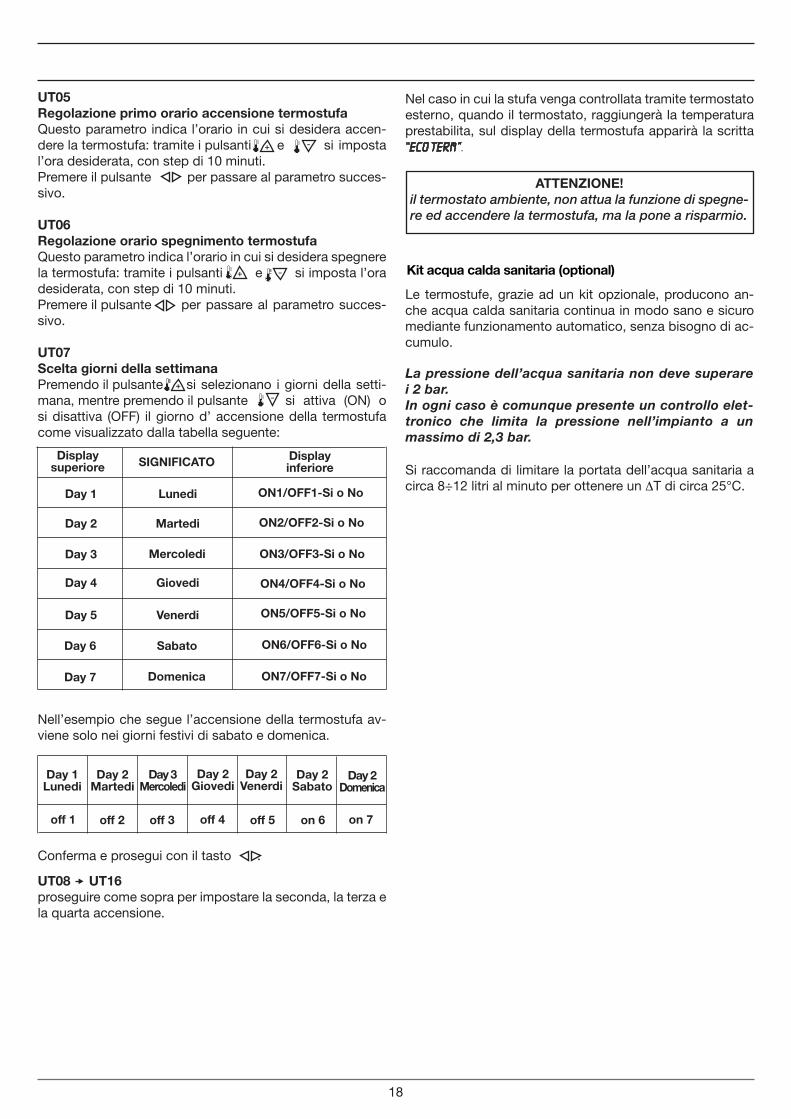
Nell’esempio che segue l’accensione della termostufa av-viene solo nei giorni festivi di sabato e domenica.
Day 1 Lunedi
off 1
Day 2 Martedi
Day 3 Mercoledi
Day 2 Giovedi
Day 2 Venerdi
Day 2 Sabato
Day 2 Domenica
off 2 off 3 off 4 off 5 on 6 on 7
Conferma e prosegui con il tasto .
Nel caso in cui la stufa venga controllata tramite termostato esterno, quando il termostato, raggiungerà la temperatura prestabilita, sul display della termostufa apparirà la scritta “ECO TERM”.
ATTENZIONE!il termostato ambiente, non attua la funzione di spegne-re ed accendere la termostufa, ma la pone a risparmio.
UT08 UT16 proseguire come sopra per impostare la seconda, la terza e la quarta accensione.
Kit acqua calda sanitaria (optional)
Le termostufe, grazie ad un kit opzionale, producono an-che acqua calda sanitaria continua in modo sano e sicuro mediante funzionamento automatico, senza bisogno di ac-cumulo.
Si raccomanda di limitare la portata dell’acqua sanitaria a circa 8÷12 litri al minuto per ottenere un ∆T di circa 25°C.
La pressione dell’acqua sanitaria non deve superare i 2 bar.In ogni caso è comunque presente un controllo elet-tronico che limita la pressione nell’impianto a un massimo di 2,3 bar.
18
i
Size: 12V
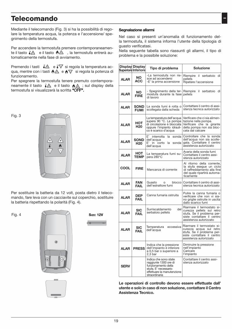
Mediante il telecomando (Fig. 3) si ha la possibilità di rego-lare la temperatura acqua, la potenza e l’accensione/ spe-gnimento della termostufa.
Per accendere la termostufa premere contemporaneamen-te il tasto e il tasto , la termostufa entrerà au-tomaticamente nella fase di avviamento.
Premendo i tasti e si regola la temperatura ac-qua, mentre con i tasti e si regola la potenza di funzionamento.Per spegnere la termostufa tenere premuto contempora-neamente il tasto e il tasto ; sul display della termostufa si visualizzerà la scritta “OFF”.
Per sostituire la batteria da 12 volt, posta dietro il teleco-mando, fare leva con un cacciavite sul coperchio, sostituire la batteria rispettando la polarità (Fig. 4).
Segnalazione allarmi
Nel caso si presenti un’anomalia di funzionamento del-la termostufa, il sistema informa l’utente della tipologia di guasto verificatasi.Nella seguente tabella sono riassunti gli allarmi, il tipo di problema e la possibile soluzione:
DisplaySuperiore
DisplayInferiore Tipo di problema Soluzione
ALAR FAN FAIL
ALAR DEP FAIL
ALARSIC FAIL
ALAR SIC FAIL
ALAR PRESS
Guasto o blocco dell’estrattore fumi
Canna fumaria ostruita
Surriscaldamento del serbatoio pellets
Temperatura eccessiva dell’acqua
Indica che la pressione dell’impianto è inferiore a 0,5 bar o superiore a 2,3 bar
Contattare il centro di assi-stenza tecnica autorizzato
Pulire la canna fumaria o verificare che non vi sia-no griglie ostruite in uscita dallo scarico fumi
Riarmare il termostato si-curezza pellets sul retro stufa. Se il problema per-siste contattare il centro assistenza autorizzato
Riarmare il termostato si-curezza acqua sul retro stufa. Se il problema per-siste contattare il centro assistenza autorizzato
Diminuire la pressione nell’impianto Caricare l’impianto
ALAR NO ACC
-La termostufa non rie-sce ad accendersi-E’ la prima accensione
Riempire il serbatoio di pelletsRipetere l’accensione
ALAR NO FIRE
- Spegnimento della ter-mostufa durante la fase di lavoro
Riempire il serbatoio di pellets
ALAR SOND FUMI
La sonda fumi è rotta o scollegata dalla scheda
Contattare il centro di assi-stenza tecnica autorizzato
ALAR HOT H20
La temperatura dell’acqua supera 90 °C. La pompa di circolazione è bloccata oppure l’impianto idrauli-co è scarico d’acqua
Verificare che ci sia alimen-tazione nella pompa.Verificare che la girante della pompa non sia bloc-cata dal calcare
ALAR SOND H20
E’ interrotta la sonda dell’acquaE’ in corto la sonda dell’acqua
Controllare che la sonda dell’acqua non sia scolle-gata. Contattare il centro assistenza autorizzato
ALAR HOT TEMP
La temperatura fumi su-pera 280°C
Avaria della sonda fumiContattare il centro assi-stenza autorizzato
COOL FIRE Mancanza di corrente
Al ritorno della corrente, la stufa esegue un ciclo di raffreddamento alla fine del quale ripartirà automa-ticamente
Le operazioni di controllo devono essere effettuate dall’ utente e solo in caso di non soluzione, contattare il Centro Assistenza Tecnico.
Fig. 3
Fig. 4
Telecomando
Size: 12V
19
SERV
Indica che sono state raggiunte 1300 ore di funzionamento della stufa. E’ necessario effettuare la manutenzione straordinaria
Contattare il centro assi-stenza autorizzato
Mancata accensioneSe durante la fase di accensione non si ha sviluppo di fiamma oppure la temperatura dei fumi non raggiunge una temperatura adeguata nell’intervallo di tempo previsto per l’accensione, la stufa viene mandata in spegnimento e sul display compare la scritta “Alar No Acc”.Premere il tasto “On/Off” per resettare l’allame. Attendere il completamento del ciclo di raffreddamento, pulire il bracie-re e procedere con una nuova accensione.
Spegnimento durante la fase di lavoroSi presenta in caso di spegnimento imprevisto della stufa durante il normale funzionamento (ad esempio per pellets finito nel serbatoio o per un guasto al motoriduttore di ca-ricamento pellets).La stufa continua a funzionare fino a che non smaltisce l’eventuale pellets presente nel braciere, dopodichè sul di-splay compare la scritta “Alar No Fire” e la stufa viene man-data in spegnimento.Premere il pulsante “On/Off” per resettare l’allarme. Atten-dere che venga completato il ciclo di raffreddamento, pulire il braciere e procedere ad una nuova accensione.
Questi allarmi ricordano che prima di effettuare un’ac-censione bisogna assicurarsi che il braciere sia comple-tamente libero, pulito e posizionato in modo corretto.
Mancanza di elettricitàNel caso in cui si verifichi una mancanza di elettricità per un periodo superiore a 1 minuto, la termostufa può emanare all’interno della casa una minima quantità di fumo: ciò non rappresenta alcun rischio per la sicurezza.Al ritorno dell’elettricità, la termostufa segnalerà sul display la scritta “Cool Fire”. Dopo il completamento del ciclo di raf-freddamento, la stufa ripartirà automaticamente portandosi nello stato di lavoro precedente all’assenza di elettricità.
Sicurezza elettrica Nel caso in cui si verifica uno sbalzo violento di elettricità (fulmine), la termostufa è protetta da un fusibile da 2,5 A 250V che si trova sul retro della termostufa, vicino al cavo di alimentazione.Fare uscire il cassettino che lo contiene e sostituirlo.
ATTENZIONE!non cercare di accendere la termostufa prima del tempo necessario, si potrebbe bloccare la stessa.In caso di blocco chiudere l’interruttore posto dietro la termostufa per 1 minuto, riaprire l’ interruttore e atten-dere 10 minuti prima di una nuova accensione.
ATTENZIONE!la presa di corrente dove si allaccia la termostufa deve essere corredata di “scarico di terra secondo la vigen-te normativa”. La Casa Costruttrice declina ogni re-sponsabilità per danni a cose e a persone causati da negligenze installative.
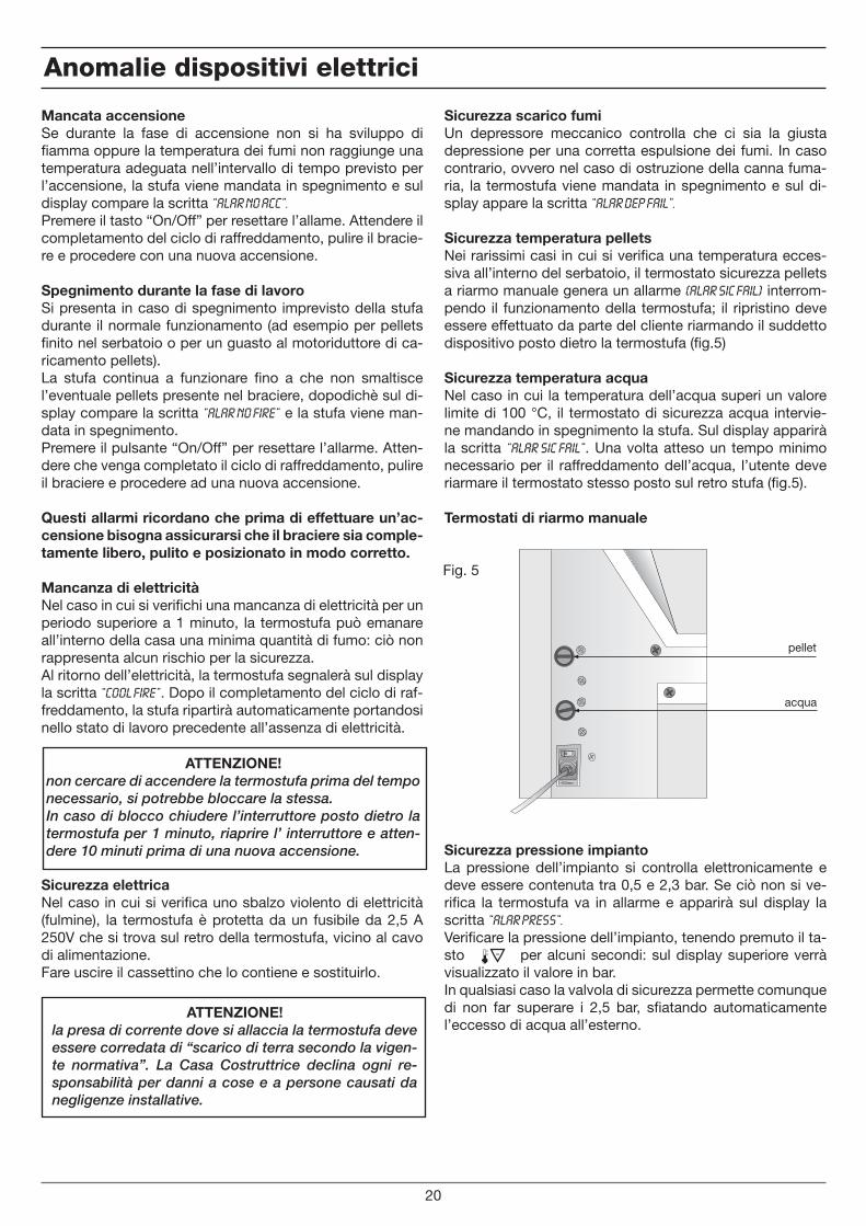
pellet
acqua
Fig. 5
Anomalie dispositivi elettrici
20
Sicurezza scarico fumiUn depressore meccanico controlla che ci sia la giusta depressione per una corretta espulsione dei fumi. In caso contrario, ovvero nel caso di ostruzione della canna fuma-ria, la termostufa viene mandata in spegnimento e sul di-splay appare la scritta “Alar Dep Fail”.
Sicurezza temperatura pelletsNei rarissimi casi in cui si verifica una temperatura ecces-siva all’interno del serbatoio, il termostato sicurezza pellets a riarmo manuale genera un allarme (Alar Sic Fail) interrom-pendo il funzionamento della termostufa; il ripristino deve essere effettuato da parte del cliente riarmando il suddetto dispositivo posto dietro la termostufa (fig.5)
Sicurezza temperatura acquaNel caso in cui la temperatura dell’acqua superi un valore limite di 100 °C, il termostato di sicurezza acqua intervie-ne mandando in spegnimento la stufa. Sul display apparirà la scritta “Alar Sic Fail”. Una volta atteso un tempo minimo necessario per il raffreddamento dell’acqua, l’utente deve riarmare il termostato stesso posto sul retro stufa (fig.5).
Termostati di riarmo manuale
Sicurezza pressione impiantoLa pressione dell’impianto si controlla elettronicamente e deve essere contenuta tra 0,5 e 2,3 bar. Se ciò non si ve-rifica la termostufa va in allarme e apparirà sul display la scritta “Alar Press”.Verificare la pressione dell’impianto, tenendo premuto il ta-sto per alcuni secondi: sul display superiore verrà visualizzato il valore in bar.In qualsiasi caso la valvola di sicurezza permette comunque di non far superare i 2,5 bar, sfiatando automaticamente l’eccesso di acqua all’esterno.
i
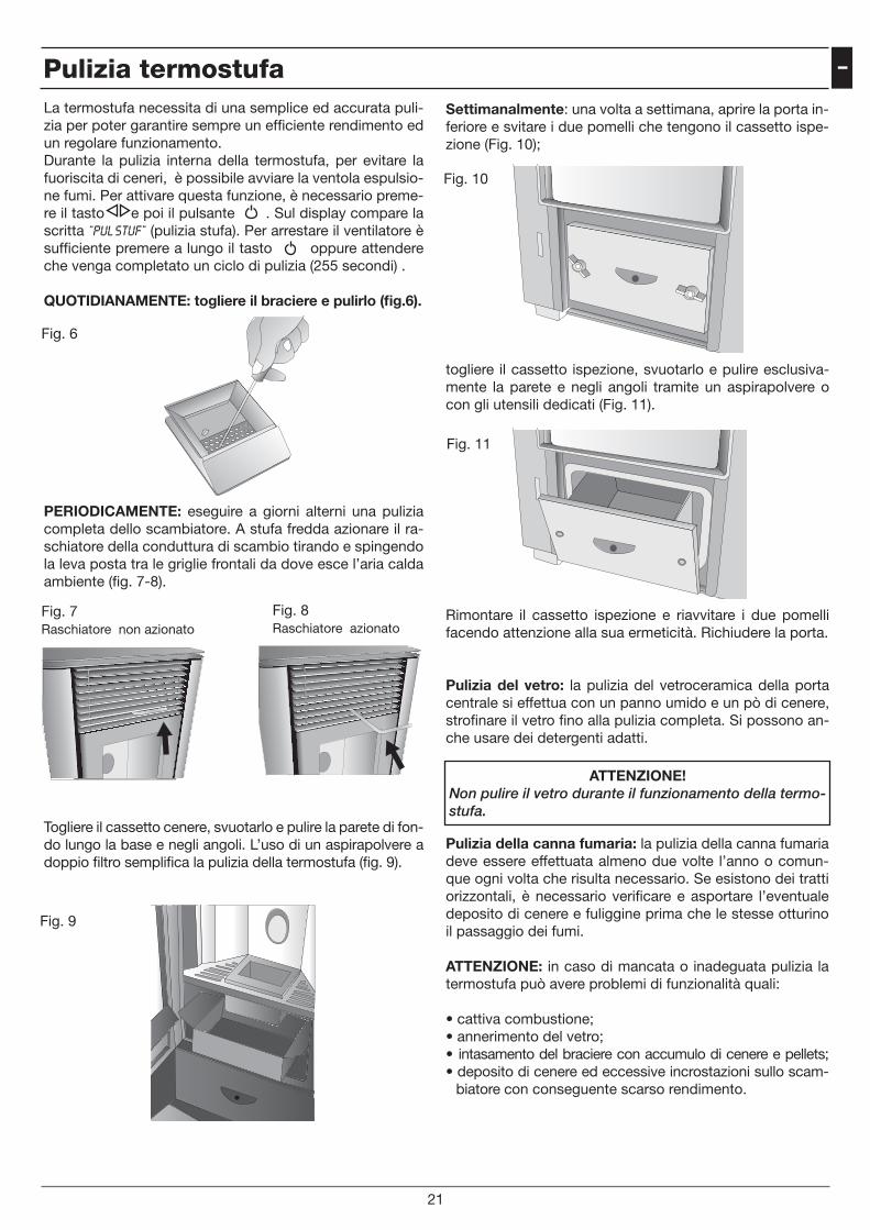
Settimanalmente: una volta a settimana, aprire la porta in-feriore e svitare i due pomelli che tengono il cassetto ispe-zione (Fig. 10);
togliere il cassetto ispezione, svuotarlo e pulire esclusiva-mente la parete e negli angoli tramite un aspirapolvere o con gli utensili dedicati (Fig. 11).
Rimontare il cassetto ispezione e riavvitare i due pomelli facendo attenzione alla sua ermeticità. Richiudere la porta.
Pulizia del vetro: la pulizia del vetroceramica della porta centrale si effettua con un panno umido e un pò di cenere, strofinare il vetro fino alla pulizia completa. Si possono an-che usare dei detergenti adatti.
Pulizia della canna fumaria: la pulizia della canna fumaria deve essere effettuata almeno due volte l’anno o comun-que ogni volta che risulta necessario. Se esistono dei tratti orizzontali, è necessario verificare e asportare l’eventuale deposito di cenere e fuliggine prima che le stesse otturino il passaggio dei fumi.
ATTENZIONE: in caso di mancata o inadeguata pulizia la termostufa può avere problemi di funzionalità quali:
• cattiva combustione; • annerimento del vetro;• intasamento del braciere con accumulo di cenere e pellets;• deposito di cenere ed eccessive incrostazioni sullo scam-
biatore con conseguente scarso rendimento.
ATTENZIONE!Non pulire il vetro durante il funzionamento della termo-stufa.
Fig. 10
Fig. 11
Pulizia termostufa
21
La termostufa necessita di una semplice ed accurata puli-zia per poter garantire sempre un efficiente rendimento ed un regolare funzionamento. Durante la pulizia interna della termostufa, per evitare la fuoriscita di ceneri, è possibile avviare la ventola espulsio-ne fumi. Per attivare questa funzione, è necessario preme-re il tasto e poi il pulsante . Sul display compare la scritta “PUL STUF” (pulizia stufa). Per arrestare il ventilatore è sufficiente premere a lungo il tasto oppure attendere che venga completato un ciclo di pulizia (255 secondi) .
QUOTIDIANAMENTE: togliere il braciere e pulirlo (fig.6).
PERIODICAMENTE: eseguire a giorni alterni una pulizia completa dello scambiatore. A stufa fredda azionare il ra-schiatore della conduttura di scambio tirando e spingendo la leva posta tra le griglie frontali da dove esce l’aria calda ambiente (fig. 7-8).
Togliere il cassetto cenere, svuotarlo e pulire la parete di fon-do lungo la base e negli angoli. L’uso di un aspirapolvere a doppio filtro semplifica la pulizia della termostufa (fig. 9).
Fig. 6
Fig. 7Raschiatore non azionato
Fig. 8Raschiatore azionato
Fig. 9
ATTENZIONE!Queste operazioni devono essere eseguite da un tecni-co qualificato, o dall’ utente che si assumerà la respon-sabilità, in caso di danni durante la manutenzione.Eseguire questa manutenzione a termostufa fredda e in assenza di elettricità. Tale manutenzione se viene ese-guita da un centro assistenza autorizzato è a carico del cliente.
NOTE
Manutenzione straordinaria
22
Cod
. 001
041
Carefully read the precautions and follow the procedures correctly.
WARNING!Do not try to install the stove;always contact authorized and trained personnel.
- In case of breakage or poor functioning always contact the Authorized Assistance Centre;any attempt to remove parts or perform maintenance on the device can expose the user to electricalshock danger. The stove contains parts whose maintenance must be done by the Authorized AssistanceCentre.
- The stove is a heating device; its parts reach extreme temperatures and contact without adequate pro-tection can provoke burns of various degrees.Pay particular attention to children.
- In case of a transfer, contact the Authorized Assistance Centre for the removal and new installation.- Do not insert fingers or other objects in the air flow exit slits.Inside the device there is a high speed fan that could cause grave personal injury. Pay particular atten-tion to children.
- Do not remain for long periods directly exposed to the flow of hot air.Direct and prolonged exposition to the cold air could be hazardous to health. Pay particular attention inrooms where there are children, the elderly or the ill.- In case the stove functions poorly, shut down the device immediately, unhook the appropriateautomatic switch and contact the Authorized Assistance Centre. The continued use of the devicein said conditions can cause fires or flashes.
WARNING!
- During the stove installation operation, keep children out of the work area to avoid unforeseen acci-dents.
- Do not block or cover in any way the body of the stove or obstruct the slits placed on the upperside.Obstructing said slits can cause fires.
- Do not use the stove in areas containing precision devices or works of art.The quality of the conserved objects may deteriorate.
- Do not expose animals or plants to direct air flow from the unit.Prolonged direct exposition to the flow of air from the stove can have negative effects on plants and ani-mals.
- Occasionally ventilate the room during the use of the device.Insufficient ventilation can be the origin of insufficient oxygen in the room.
- Do not expose the stove to contact with water.The electrical insulation could be damaged, with the consequent possibilities of electrocution andbreakage due to the thermal extremes.
- Verify the installation conditions to locate eventual damage.- Do not use inflammable gas near the stove.- Unhook the automatic switch if the device will not be used for long periods of time.- We check the start up of all our stoves.

2
Norms and conformity declarations
Legislation• Our company declares that the stoveconforms to the following norms for ECEuropean Directive marking.
• 2006/42 EC (machines directive).• 89/336 EC and 2004/108 EC (EMC directi-ve) and successive amendments.
• 2006/95 EC (low voltage directive) and suc-cessive amendments.
• 89/106 EC (construction products).• For installation in Italy refer to the UNI10683/98 or successive modifications; thetechnician installing the hydrothermal sanitarysystem will issue the declaration of conformityaccording to L. 37/2008.The installation ofappliance has to be in accordance with localand national laws and with European norms.
• EN 60335-1 - EN 50165 - EN 50366 - EN55014-1 - EN 61000-3-2 - EN 61000-3-3 -EN 14785.
ResponsibilityThe manufacturer declines every direct orindirect, civil or penal responsibility due to:• Poor maintenance.• Failure to observe the instructions contai-ned in the manuals.
• Use in non-conformity with the safety direc-tives.
• Installation in non-conformity with thenorms in force in the country.
• Installation by unqualified or untrained per-sonnel.
• Modifications and repairs not authorized bythe manufacturer.
• Use of non-original replacement parts.• Exceptional events.• Use of pellets not approved by the manu-facturer.
Installation
FlueThe flue must meet the following require-ments:• No other type of chimney, stove, boiler orhood vent must be connected (Pict.1).
• It must be adequately distanced from com-bustible or inflammable material by meansof an air cavity or opportune insulation.
• The internal section must be uniform, prefe-rably circular: the square or rectangularsections must have rounded corners with aradius of no less than 20 mm, a maximumrelationship between the sides of 1.5; thewalls as smooth as possible with no nar-rowed sections, regular curves and nodiscontinuities, with deviations from theaxis not more than 45°.
NO NO YES
Pict.1: methods for installing the flue
3
GBInstallation
NOYES
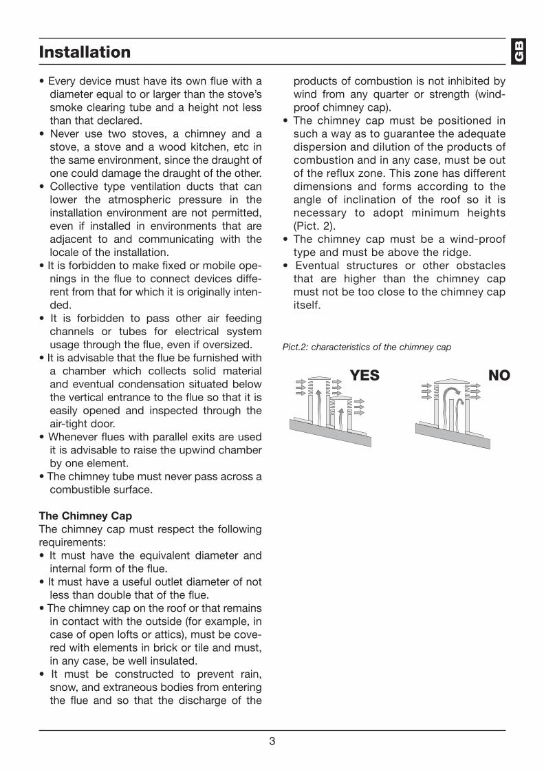
Pict.2: characteristics of the chimney cap
• Every device must have its own flue with adiameter equal to or larger than the stove’ssmoke clearing tube and a height not lessthan that declared.
• Never use two stoves, a chimney and astove, a stove and a wood kitchen, etc inthe same environment, since the draught ofone could damage the draught of the other.
• Collective type ventilation ducts that canlower the atmospheric pressure in theinstallation environment are not permitted,even if installed in environments that areadjacent to and communicating with thelocale of the installation.
• It is forbidden to make fixed or mobile ope-nings in the flue to connect devices diffe-rent from that for which it is originally inten-ded.
• It is forbidden to pass other air feedingchannels or tubes for electrical systemusage through the flue, even if oversized.
• It is advisable that the flue be furnished witha chamber which collects solid materialand eventual condensation situated belowthe vertical entrance to the flue so that it iseasily opened and inspected through theair-tight door.
• Whenever flues with parallel exits are usedit is advisable to raise the upwind chamberby one element.
• The chimney tube must never pass across acombustible surface.
The Chimney CapThe chimney cap must respect the followingrequirements:• It must have the equivalent diameter andinternal form of the flue.
• It must have a useful outlet diameter of notless than double that of the flue.
• The chimney cap on the roof or that remainsin contact with the outside (for example, incase of open lofts or attics), must be cove-red with elements in brick or tile and must,in any case, be well insulated.
• It must be constructed to prevent rain,snow, and extraneous bodies from enteringthe flue and so that the discharge of the
products of combustion is not inhibited bywind from any quarter or strength (wind-proof chimney cap).
• The chimney cap must be positioned insuch a way as to guarantee the adequatedispersion and dilution of the products ofcombustion and in any case, must be outof the reflux zone. This zone has differentdimensions and forms according to theangle of inclination of the roof so it isnecessary to adopt minimum heights(Pict. 2).
• The chimney cap must be a wind-prooftype and must be above the ridge.
• Eventual structures or other obstaclesthat are higher than the chimney capmust not be too close to the chimney capitself.
4
Sizing
The adjacent locale must not be used asa garage or be a space without ventila-tion or air exchange, a storage area forcombustible material or used for anactivity that has a fire hazard.
According to the norm UNI 10683/98, thestove must not be in the same environmentwhere extractors, type B gas devices or in anycase, devices that create lower atmosphericpressure in the locale are found.
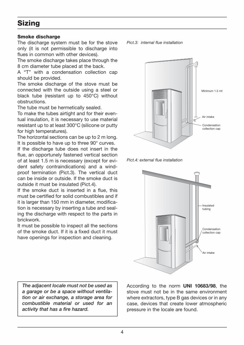
Smoke dischargeThe discharge system must be for the stoveonly (it is not permissible to discharge intoflues in common with other devices).The smoke discharge takes place through the8 cm diameter tube placed at the back.A “T” with a condensation collection capshould be provided.The smoke discharge of the stove must beconnected with the outside using a steel orblack tube (resistant up to 450°C) withoutobstructions.The tube must be hermetically sealed.To make the tubes airtight and for their even-tual insulation, it is necessary to use materialresistant up to at least 300°C (silicone or puttyfor high temperatures).The horizontal sections can be up to 2 m long.It is possible to have up to three 90° curves.If the discharge tube does not insert in theflue, an opportunely fastened vertical sectionof at least 1.5 m is necessary (except for evi-dent safety contraindications) and a wind-proof termination (Pict.3). The vertical ductcan be inside or outside. If the smoke duct isoutside it must be insulated (Pict.4).If the smoke duct is inserted in a flue, thismust be certified for solid combustibles and ifit is larger than 150 mm in diameter, modifica-tion is necessary by inserting a tube and seal-ing the discharge with respect to the parts inbrickwork.It must be possible to inspect all the sectionsof the smoke duct. If it is a fixed duct it musthave openings for inspection and cleaning.
Air intake
Condensationcollection cap
Minimum 1.5 mt
Air intake
Condensationcollection cap
Pict.3: internal flue installation
Pict.4: external flue installation
Insulatedtubing

5
������
����
���
����
���
���
����
���
��
������
��
���
���
������
����
���������
�����
���
�����
Ø 50mm Ø 80mm
Sizing GB
Sizing of the boiler stove
External air intake
The stove must be furnished with the air neces-sary to guarantee the regular functioning of thecombustion and an environmental well being.• Be sure that the room where the stove isinstalled has sufficient aeration and, ifnecessary, install an air intake duct with aminimum recommended diameter of 50 mmto bring in air from the outside.
• The external air intake must communicatewith the stove and positioned so that it isnot obstructed. It must be protected with apermanent non-closable grill or other suita-ble protection provided that the minimumdiameter is not reduced.
• The air flow can also be acquired from alocale adjacent to where the stove is instal-led as long as that flow can freely cross thepermanent non-closable openings thatcommunicate with the outside.
• The presence in the local adjacent to wherethe stove is installed, of other devices in useor of suction devices that cause a contrarydraught effect must not create a lower airpressure in the locale than in the outsideenvironment.
• In the adjacent locale the permanent ope-nings must respond to the requisites whichare listed in the points above.
Sizing
air intakesmokeoutlet
water inlet water outlet
Approximative dimensions (mm).
6
40 cm.
20 cm.20 cm.
40 cm.
40 cm.20 cm.
40 cm.
80 cm.
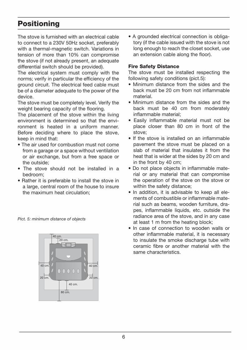
The stove is furnished with an electrical cableto connect to a 230V 50Hz socket, preferablywith a thermal-magnetic switch. Variations intension of more than 10% can compromisethe stove (if not already present, an adequatedifferential switch should be provided).The electrical system must comply with thenorms; verify in particular the efficiency of theground circuit. The electrical feed cable mustbe of a diameter adequate to the power of thedevice.The stove must be completely level. Verify theweight bearing capacity of the flooring.The placement of the stove within the livingenvironment is determined so that the envi-ronment is heated in a uniform manner.Before deciding where to place the stove,keep in mind that:• The air used for combustion must not comefrom a garage or a space without ventilationor air exchange, but from a free space orthe outside;
• The stove should not be installed in abedroom;
• Rather it is preferable to install the stove ina large, central room of the house to insurethe maximum heat circulation;
Positioning
• A grounded electrical connection is obliga-tory (if the cable issued with the stove is notlong enough to reach the closet socket, usean extension cable along the floor).
Fire Safety DistanceThe stove must be installed respecting thefollowing safety conditions (pict.5):• Minimum distance from the sides and theback must be 20 cm from not inflammablematerial.
• Minimum distance from the sides and theback must be 40 cm from moderatelyinflammable material;
• Easily inflammable material must not beplace closer than 80 cm in front of thestove;
• If the stove is installed on an inflammablepavement the stove must be placed on aslab of material that insulates it from theheat that is wider at the sides by 20 cm andin the front by 40 cm;
• Do not place objects in inflammable mate-rial or any material that can compromisethe operation of the stove on the stove orwithin the safety distance;
• In addition, it is advisable to keep all ele-ments of combustible or inflammable mate-rial such as beams, wooden furniture, dra-pes, inflammable liquids, etc. outside theradiance area of the stove, and in any caseat least 1 m from the heating block;
• In case of connection to wooden walls orother inflammable material, it is necessaryto insulate the smoke discharge tube withceramic fibre or another material with thesame characteristics.
Pict. 5: minimum distance of objects
7
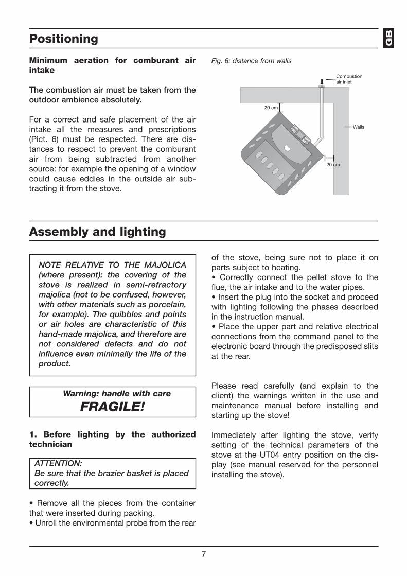
Fig. 6: distance from walls
20 cm.
20 cm.
Walls
Combustionair inlet
Positioning
Minimum aeration for comburant airintake
The combustion air must be taken from theoutdoor ambience absolutely.
For a correct and safe placement of the airintake all the measures and prescriptions(Pict. 6) must be respected. There are dis-tances to respect to prevent the comburantair from being subtracted from anothersource: for example the opening of a windowcould cause eddies in the outside air sub-tracting it from the stove.
Assembly and lighting
NOTE RELATIVE TO THE MAJOLICA(where present): the covering of thestove is realized in semi-refractorymajolica (not to be confused, however,with other materials such as porcelain,for example). The quibbles and pointsor air holes are characteristic of thishand-made majolica, and therefore arenot considered defects and do notinfluence even minimally the life of theproduct.
Warning: handle with care
FRAGILE!
ATTENTION:Be sure that the brazier basket is placedcorrectly.
• Remove all the pieces from the containerthat were inserted during packing.• Unroll the environmental probe from the rear
of the stove, being sure not to place it onparts subject to heating.• Correctly connect the pellet stove to theflue, the air intake and to the water pipes.• Insert the plug into the socket and proceedwith lighting following the phases describedin the instruction manual.• Place the upper part and relative electricalconnections from the command panel to theelectronic board through the predisposed slitsat the rear.
Please read carefully (and explain to theclient) the warnings written in the use andmaintenance manual before installing andstarting up the stove!
Immediately after lighting the stove, verifysetting of the technical parameters of thestove at the UT04 entry position on the dis-play (see manual reserved for the personnelinstalling the stove).
1. Before lighting by the authorizedtechnician
GB
8
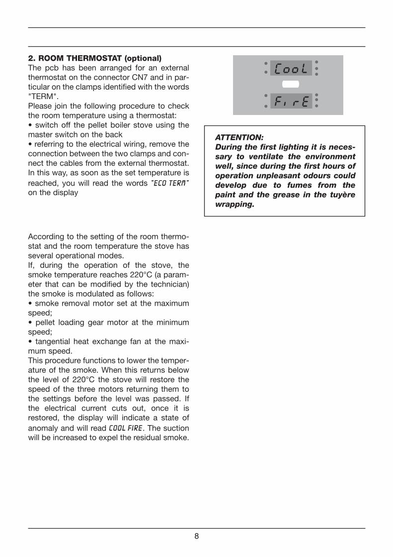
2. ROOM THERMOSTAT (optional)The pcb has been arranged for an externalthermostat on the connector CN7 and in par-ticular on the clamps identified with the words"TERM".Please join the following procedure to checkthe room temperature using a thermostat:• switch off the pellet boiler stove using themaster switch on the back• referring to the electrical wiring, remove theconnection between the two clamps and con-nect the cables from the external thermostat.In this way, as soon as the set temperature isreached, you will read the words "" EE CC OO TT EE RR MM ""
on the display
According to the setting of the room thermo-stat and the room temperature the stove hasseveral operational modes.If, during the operation of the stove, thesmoke temperature reaches 220°C (a param-eter that can be modified by the technician)the smoke is modulated as follows:• smoke removal motor set at the maximumspeed;• pellet loading gear motor at the minimumspeed;• tangential heat exchange fan at the maxi-mum speed.This procedure functions to lower the temper-ature of the smoke. When this returns belowthe level of 220°C the stove will restore thespeed of the three motors returning them tothe settings before the level was passed. Ifthe electrical current cuts out, once it isrestored, the display will indicate a state ofanomaly and will read CC OO OO LL FF II RR EE. The suctionwill be increased to expel the residual smoke.
ATTENTION:During the first lighting it is neces-sary to ventilate the environmentwell, since during the first hours ofoperation unpleasant odours coulddevelop due to fumes from thepaint and the grease in the tuyèrewrapping.
9
GBMaintenance performed by the A.A.C.
Operations to be performed by theAuthorized Assistance Centre every sea-son before the lighting.• A general cleaning inside and outside.• A careful cleaning of the exchange tubes.• A careful cleaning and disincrustation of thecrucible and the relative cavity.
• Clean the motors, checking the play andfastenings of the mechanisms.
• Clean the smoke channel (substitute thetube gaskets) and smoke extractor fancavity.
• Clean pressure switch, sostitute siliconetube.
• Check the probe.• Replace the batteries in the clock on theelectronic board.
• Clean, inspect and disincrust the lightingresistor compartment, replacing it if neces-sary.
• Clean/check the synoptic panel.• Visually inspect the electrical cables, theconnections and the electrical power cable.
• Clean the pellet container and verify theplay with the screw feeder gear motor.
• Replace the door seals.• Test functions, loading the screw feeder,lighting, 10 minutes of operation and shutdown.
• Check the electrical parts and the electroniccomponents.
• Check and possible cleaning of the canali-sation.
GB
3
Dear Customer,Congratulations on your purchasing an pellet boiler stove! We would like to remind you that pellet boiler stoves are the most innovative heating solution generated by the most advanced technology, characterised by high-quality manufactu-ring as well as a simple and elegant design. Ideal for any type of room, these products contribute to comfort thanks to the cosy heat that only flames can radiate. This manual will help you use your pellet boiler stove properly. Therefore, read it carefully and thoroughly before using the unit.Stoves are fuelled only by wood pellets, up to 6mm in diameter. They are fitted with an exchanger that allows reaching a heat yield of approx. 90%. Pellet boiler stoves are fitted with a timer-thermostat that ensures an autonomous management of the stove as it can be pro-grammed to turn on and off up to 4 times per week. Pellet boiler stoves take the heat to the radiators in the heating system, with a thermal power that is adjusted according to the space to be heated: just set the heating system water temperature manually. Recommended temperature: between 60° and 75°.Pellet boiler stoves are fitted with cross-flow fans for hot air distribution which distributes heat through a forced-air system in the room where the stove is installed.Thanks to an optional kit, these stoves also produce continuous domestic hot water healthily, safely and automatically, wi-thout the need for water storing.Pellet boiler stoves have been equipped with highly advanced automatic devices and control and safety systems that ensure efficient and practical operation.Installation and maintenance operations should be carried out by qualified personnel, in compliance with the laws in force and according to the indications specified by the Manufacturer.This use and maintenance manual is an integral part of the product.Before using, installing or servicing the product, read the indications contained in this manual carefully.This pellet boiler stove should only be used for the intended use it has been designed for. Therefore, the user shall be responsible for any damage to people, animals or things resulting from misuse of the product.
Installation should be carried out by qualified personnel, who will be fully responsible for installing the product and ensuring its proper operation. The Manufacturer shall not be responsible in case of installation by unqualified personnel or without complying with the general warnings and installation instructions.
For safety reasons, it is advisable to remember that:
• The pellet boiler stove should not be used by children or handicapped people not being assisted;• do not touch the pellet boiler stove with wet parts of the body and/or bare feet;• it is forbidden to modify the safety or adjustment devices without the manufacturer’s authorisation or indications;• do not pull, disconnect or twist the electric cables coming out of the boiler even when it is disconnected from the mains;
• avoid covering or reducing the combustion air duct, which is essential for correct combustion;• keep all the packing elements out of the reach of children or handicapped people not being assisted.
In the event of a fire, disconnect the power supply, use an extinguisher and call the fire fighters if necessary. After that con-tact the Authorised Assistance Centre.
After unpacking the unit, check all the parts are in good conditions and that no item is missing. Otherwise, contact the dealer from which you purchased your pellet boiler stove.Before installing the unit, it is advisable to clean all the ducts and pipes in the system very carefully in order to remove any scales that may affect the stove correct operation.Whenever the pellet boiler stove is not used for a long time, it is advisable to carry out the following operations:• disconnect the power supply plug;• close the water cocks of both the heating and the hot water systems;• in case of risk of frost, empty the heating and hot water systems.The pellet boiler stove extraordinary maintenance should be carried out at least once a year. This operation should be scheduled in advance with the Technical Assistance Service and shall be at the Client’s expense.
CAUTION!The first two or three times your pellet boiler stove is started, fumes emitted by the varnish may cause unpleasant smells due to hardening. Therefore, it is advisable to air the room properly, and avoid staying long in front of the pellet boiler stove.
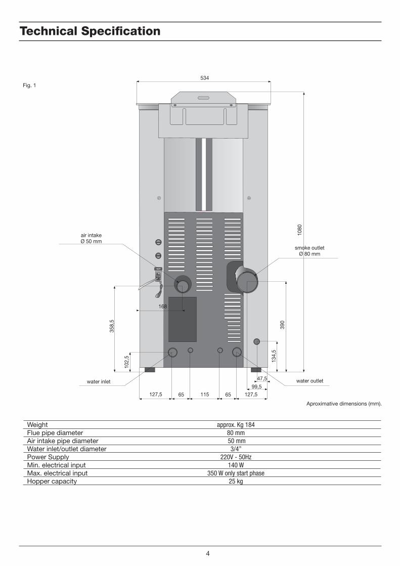
technical Specification
approx. Kg 18480 mm 50 mm
3/4” 220V - 50Hz
140 W350 W only start phase
25 kg
WeightFlue pipe diameterAir intake pipe diameterWater inlet/outlet diameterPower SupplyMin. electrical inputMax. electrical inputHopper capacity
Fig. 1
4
47,5
99,5127,5 65 115 65 127,5
168
102,
5
358,
5
134,
5
390
1080
534
air intakeØ 50 mm
smoke outletØ 80 mm
water outletwater inlet
Aproximative dimensions (mm).
GB
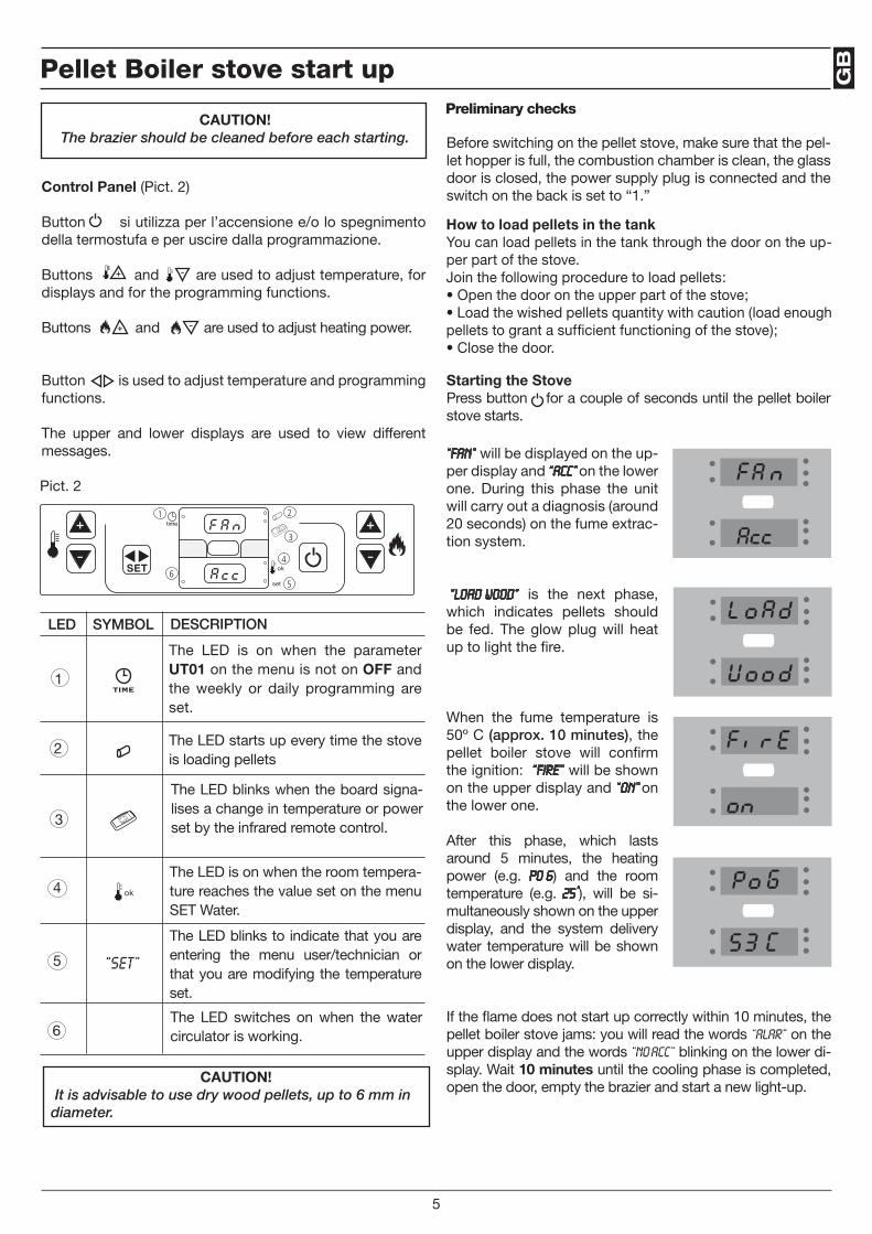
Starting the StovePress button for a couple of seconds until the pellet boiler stove starts.
Pellet Boiler stove start up
CAUTION! The brazier should be cleaned before each starting. Before switching on the pellet stove, make sure that the pel-
let hopper is full, the combustion chamber is clean, the glass door is closed, the power supply plug is connected and the switch on the back is set to “1.”
The LED is on when the parameter UT01 on the menu is not on OFF and the weekly or daily programming are set.
CAUTION! It is advisable to use dry wood pellets, up to 6 mm in diameter.
“Fan” will be displayed on the up-per display and “ACC” on the lower one. During this phase the unit will carry out a diagnosis (around 20 seconds) on the fume extrac-tion system.
“LOAD WOOD” is the next phase, which indicates pellets should be fed. The glow plug will heat up to light the fire.
When the fume temperature is 50º C (approx. 10 minutes), the pellet boiler stove will confirm the ignition: “FirE” will be shown on the upper display and “ON” on the lower one.
After this phase, which lasts around 5 minutes, the heating power (e.g. po 6) and the room temperature (e.g. 25°), will be si-multaneously shown on the upper display, and the system delivery water temperature will be shown on the lower display.
If the flame does not start up correctly within 10 minutes, the pellet boiler stove jams: you will read the words “ALAR” on the upper display and the words “NO ACC” blinking on the lower di-splay. Wait 10 minutes until the cooling phase is completed, open the door, empty the brazier and start a new light-up.
Pict. 2
Preliminary checks
5
6
1 2
3
4
5
“SET”
LED SYMBOL DESCRIPTION
1
2
3
4
5
6
The LED starts up every time the stove is loading pellets
The LED blinks when the board signa-lises a change in temperature or power set by the infrared remote control.
The LED is on when the room tempera-ture reaches the value set on the menu SET Water.
The LED blinks to indicate that you are entering the menu user/technician or that you are modifying the temperature set.
The LED switches on when the water circulator is working.
Control Panel (Pict. 2)
Button si utilizza per l’accensione e/o lo spegnimento della termostufa e per uscire dalla programmazione.
Buttons and are used to adjust temperature, for displays and for the programming functions.
Buttons and are used to adjust heating power.
Button is used to adjust temperature and programming functions.
The upper and lower displays are used to view different messages.
How to load pellets in the tankYou can load pellets in the tank through the door on the up-per part of the stove.Join the following procedure to load pellets:• Open the door on the upper part of the stove;• Load the wished pellets quantity with caution (load enough pellets to grant a sufficient functioning of the stove);• Close the door.
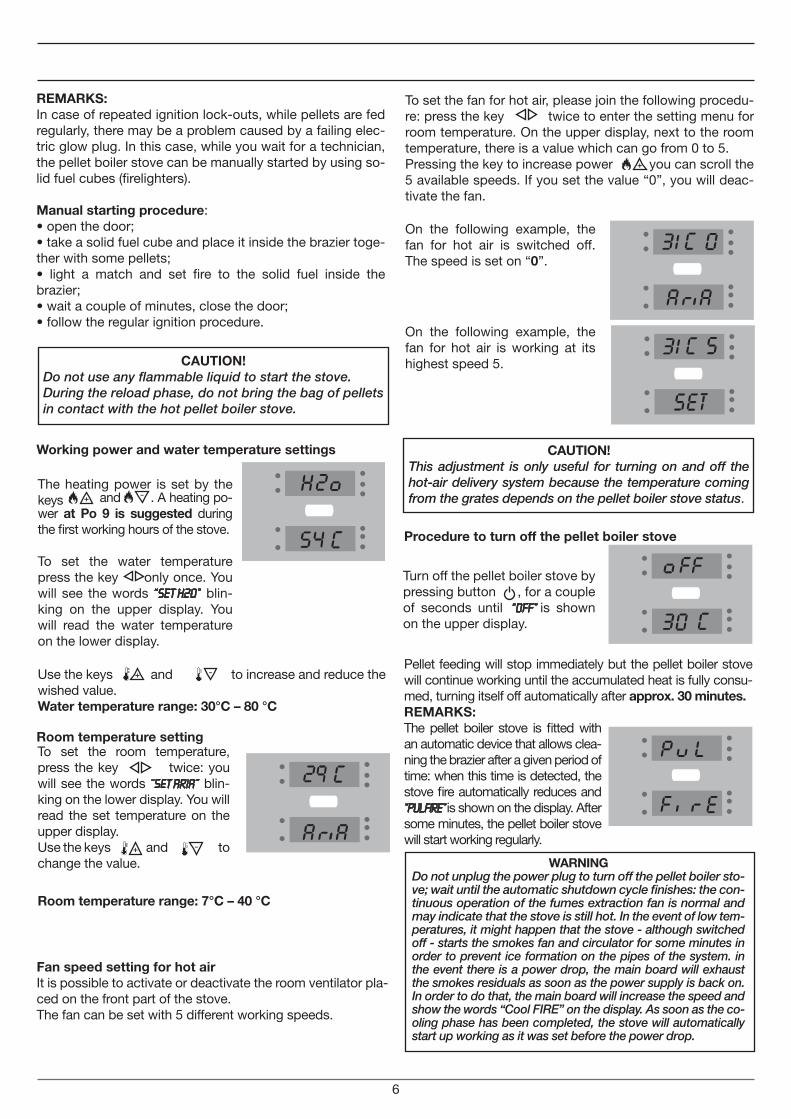
Turn off the pellet boiler stove by pressing button , for a couple of seconds until “OFF” is shown on the upper display.
REMARKS:In case of repeated ignition lock-outs, while pellets are fed regularly, there may be a problem caused by a failing elec-tric glow plug. In this case, while you wait for a technician, the pellet boiler stove can be manually started by using so-lid fuel cubes (firelighters).
Manual starting procedure:• open the door;• take a solid fuel cube and place it inside the brazier toge-ther with some pellets;• light a match and set fire to the solid fuel inside the brazier;• wait a couple of minutes, close the door; • follow the regular ignition procedure.
Working power and water temperature settings
Room temperature setting
To set the room temperature, press the key twice: you will see the words “SET ARIA” blin-king on the lower display. You will read the set temperature on the upper display.Use the keys and to change the value.
Use the keys and to increase and reduce the wished value.Water temperature range: 30°C – 80 °C
Procedure to turn off the pellet boiler stove
Pellet feeding will stop immediately but the pellet boiler stove will continue working until the accumulated heat is fully consu-med, turning itself off automatically after approx. 30 minutes.
The heating power is set by the keys and . A heating po-wer at Po 9 is suggested during the first working hours of the stove.
To set the water temperature press the key only once. You will see the words “Set H2o” blin-king on the upper display. You will read the water temperature on the lower display.
REMARKS:The pellet boiler stove is fitted with an automatic device that allows clea-ning the brazier after a given period of time: when this time is detected, the stove fire automatically reduces and “PUL FIRE” is shown on the display. After some minutes, the pellet boiler stove will start working regularly.
6
Room temperature range: 7°C – 40 °C
Fan speed setting for hot airIt is possible to activate or deactivate the room ventilator pla-ced on the front part of the stove.The fan can be set with 5 different working speeds.
To set the fan for hot air, please join the following procedu-re: press the key twice to enter the setting menu for room temperature. On the upper display, next to the room temperature, there is a value which can go from 0 to 5.Pressing the key to increase power you can scroll the 5 available speeds. If you set the value “0”, you will deac-tivate the fan.
On the following example, the fan for hot air is switched off. The speed is set on “0”.
On the following example, the fan for hot air is working at its highest speed 5.
WARNINGDo not unplug the power plug to turn off the pellet boiler sto-ve; wait until the automatic shutdown cycle finishes: the con-tinuous operation of the fumes extraction fan is normal and may indicate that the stove is still hot. In the event of low tem-peratures, it might happen that the stove - although switched off - starts the smokes fan and circulator for some minutes in order to prevent ice formation on the pipes of the system. in the event there is a power drop, the main board will exhaust the smokes residuals as soon as the power supply is back on. In order to do that, the main board will increase the speed and show the words “Cool FIRE” on the display. As soon as the co-oling phase has been completed, the stove will automatically start up working as it was set before the power drop.
CAUTION!Do not use any flammable liquid to start the stove.During the reload phase, do not bring the bag of pellets in contact with the hot pellet boiler stove.
CAUTION!This adjustment is only useful for turning on and off the hot-air delivery system because the temperature coming from the grates depends on the pellet boiler stove status.
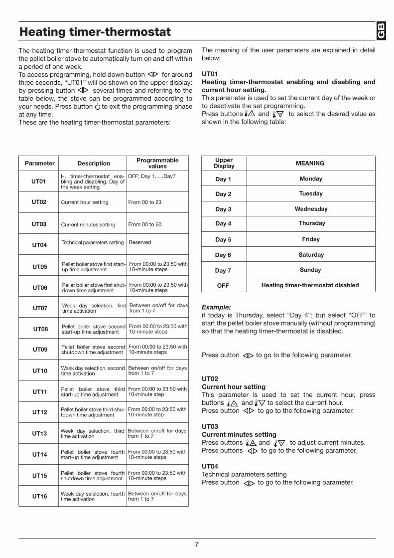
GB
7
heating timer-thermostat
Parameter Description Programmable values
UT01OFF; Day 1, ...,Day7H. timer-thermostat ena-
bling and disabling. Day of the week setting
UT02 From 00 to 23Current hour setting
UT03 From 00 to 60Current minutes setting
UT04 Reserved Technical parameters setting
UT05 From 00:00 to 23:50 with 10-minute steps
Pellet boiler stove first start-up time adjustment
UT06 From 00:00 to 23:50 with 10-minute steps
Pellet boiler stove first shut-down time adjustment
UT07 Between on/off for days from 1 to 7
Week day selection, first time activation
UT08 From 00:00 to 23:50 with 10-minute steps
Pellet boiler stove second start-up time adjustment
UT09 From 00:00 to 23:50 with 10-minute steps
Pellet boiler stove second shutdown time adjustment
UT10 Between on/off for days from 1 to 7
Week day selection, second time activation
UT11 From 00:00 to 23:50 with 10-minute step
Pellet boiler stove third start-up time adjustment
UT12 From 00:00 to 23:50 with 10-minute step
Pellet boiler stove third shu-tdown time adjustment
UT13 Between on/off for days from 1 to 7
Week day selection, third time activation
UT14 From 00:00 to 23:50 with 10-minute steps
Pellet boiler stove fourth start-up time adjustment
UT15 From 00:00 to 23:50 with 10-minute steps
Pellet boiler stove fourth shutdown time adjustment
UT16 Between on/off for days from 1 to 7
Week day selelction, fourth time activation
The meaning of the user parameters are explained in detail below:
UT01 Heating timer-thermostat enabling and disabling and current hour setting.This parameter is used to set the current day of the week or to deactivate the set programming.Press buttons and to select the desired value as shown in the following table:
UpperDisplay MEANING
Day 1
Day 2
Day 3
Day 4
Day 5
Day 6
Day 7
OFF
Example: if today is Thursday, select “Day 4”; but select “OFF” to start the pellet boiler stove manually (without programming) so that the heating timer-thermostat is disabled.
Press button to go to the following parameter.
UT02 Current hour settingThis parameter is used to set the current hour, press buttons and to select the current hour. Press button to go to the following parameter.
UT03Current minutes settingPress buttons and to adjust current minutes.Press buttons to go to the following parameter.
UT04Technical parameters settingPress button to go to the following parameter.
The heating timer-thermostat function is used to program the pellet boiler stove to automatically turn on and off within a period of one week.To access programming, hold down button for around three seconds, “UT01” will be shown on the upper display: by pressing button several times and referring to the table below, the stove can be programmed according to your needs. Press button to exit the programming phase at any time.These are the heating timer-thermostat parameters:
Tuesday
Wednesday
Thursday
Friday
Saturday
Sunday
Heating timer-thermostat disabled
Monday
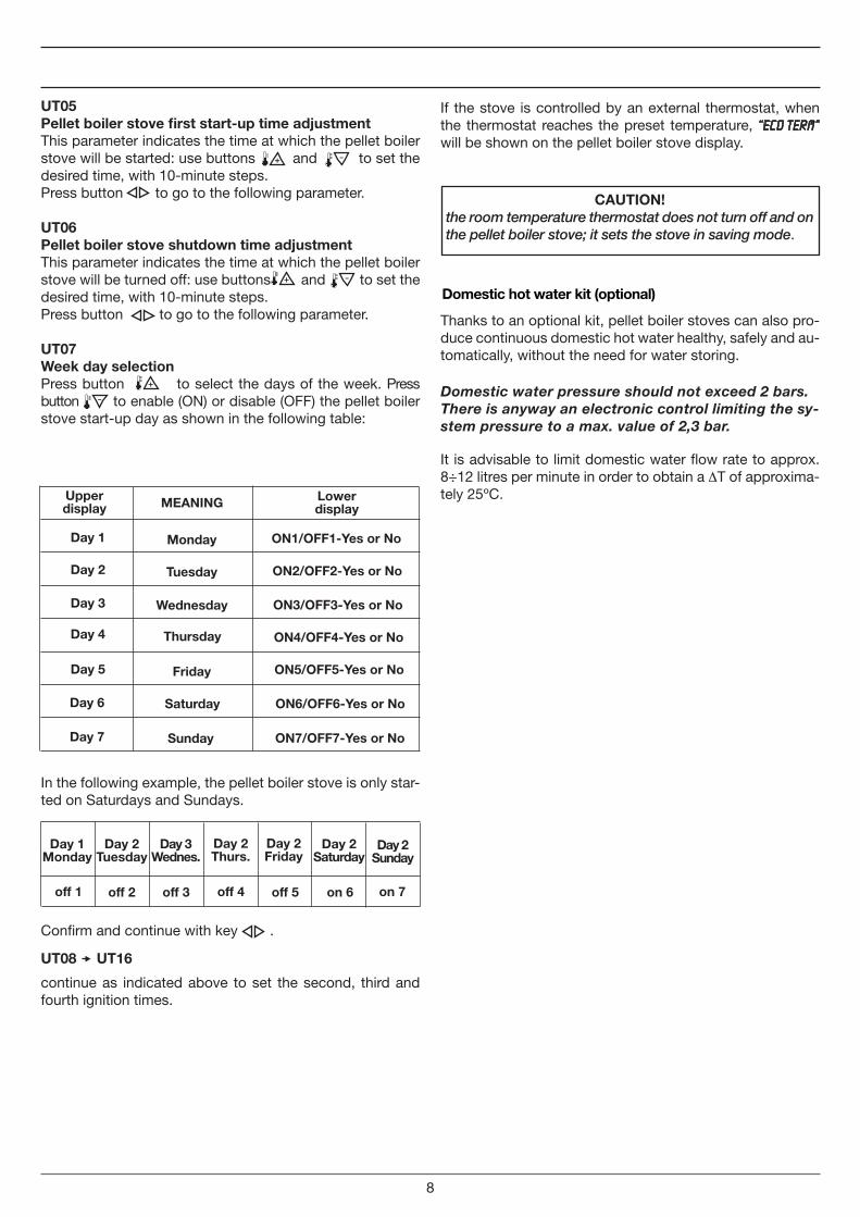
8
UT05Pellet boiler stove first start-up time adjustmentThis parameter indicates the time at which the pellet boiler stove will be started: use buttons and to set the desired time, with 10-minute steps.Press button to go to the following parameter.
UT06Pellet boiler stove shutdown time adjustmentThis parameter indicates the time at which the pellet boiler stove will be turned off: use buttons and to set the desired time, with 10-minute steps.Press button to go to the following parameter.
UT07Week day selectionPress button to select the days of the week. Press button to enable (ON) or disable (OFF) the pellet boiler stove start-up day as shown in the following table:
Upper display MEANING
Day 1
Day 2
Day 3
Day 4
Day 5
Day 6
Day 7
Lower display
In the following example, the pellet boiler stove is only star-ted on Saturdays and Sundays.
off 1 off 2 off 3 off 4 off 5 on 6 on 7
Confirm and continue with key .
If the stove is controlled by an external thermostat, when the thermostat reaches the preset temperature, “ECO TERM” will be shown on the pellet boiler stove display.
CAUTION!the room temperature thermostat does not turn off and on the pellet boiler stove; it sets the stove in saving mode.
UT08 UT16
continue as indicated above to set the second, third and fourth ignition times.
Domestic hot water kit (optional)
Thanks to an optional kit, pellet boiler stoves can also pro-duce continuous domestic hot water healthy, safely and au-tomatically, without the need for water storing.
It is advisable to limit domestic water flow rate to approx. 8÷12 litres per minute in order to obtain a ∆T of approxima-tely 25ºC.
Domestic water pressure should not exceed 2 bars.There is anyway an electronic control limiting the sy-stem pressure to a max. value of 2,3 bar.
Monday
Tuesday
Wednesday
Thursday
Friday
Saturday
Sunday
ON1/OFF1-Yes or No
ON2/OFF2-Yes or No
ON3/OFF3-Yes or No
ON4/OFF4-Yes or No
ON5/OFF5-Yes or No
ON6/OFF6-Yes or No
ON7/OFF7-Yes or No
Day 1 Monday
Day 2 Tuesday
Day 3 Wednes.
Day 2 Thurs.
Day 2 Friday
Day 2 Saturday
Day 2 Sunday
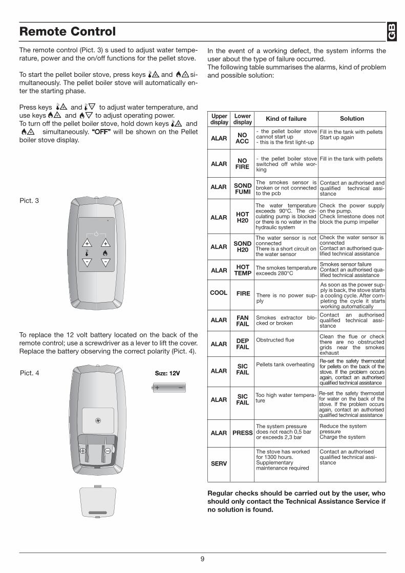
GB
In the event of a working defect, the system informs the user about the type of failure occurred.The following table summarises the alarms, kind of problem and possible solution:
Upper display
Lower display Kind of failure Solution
ALAR FAN FAIL
ALAR DEP FAIL
ALARSIC FAIL
ALAR SIC FAIL
ALAR PRESS
Smokes extractor blo-cked or broken
Obstructed flue
Pellets tank overheating
Too high water tempera-ture
The system pressure does not reach 0,5 bar or exceeds 2,3 bar
Contact an authorised qualified technical assi-stance
Clean the flue or check there are no obstructed grids near the smokes exhaust
Re-set the safety thermostat for pellets on the back of the stove. If the problem occurs again, contact an authorised qualified technical assistance
Re-set the safety thermostat for water on the back of the stove. If the problem occurs again, contact an authorised qualified technical assistance
Reduce the system pressureCharge the system
ALAR NO ACC
- the pellet boiler stove cannot start up- this is the first light-up
Fill in the tank with pelletsStart up again
ALAR NO FIRE
- the pellet boiler stove switched off while wor-king
Fill in the tank with pellets
ALAR SOND FUMI
The smokes sensor is broken or not connected to the pcb
Contact an authorised and qualified technical assi-stance
ALAR HOT H20
The water temperature exceeds 90°C. The cir-culating pump is blocked or there is no water in the hydraulic system
Check the power supply on the pump.Check limestone does not block the pump impeller
ALAR SOND H20
The water sensor is not connectedThere is a short circuit on the water sensor
Check the water sensor is connectedContact an authorised qua-lified technical assistance
ALAR HOT TEMP
The smokes temperature exceeds 280°C
Smokes sensor failureContact an authorised qua-lified technical assistance
COOL FIRE There is no power sup-ply
As soon as the power sup-ply is back, the stove starts a cooling cycle. After com-pleting the cycle it starts working automatically
Regular checks should be carried out by the user, who should only contact the Technical Assistance Service if no solution is found.
9
SERv
The stove has worked for 1300 hours. Supplementary maintenance required
Contact an authorised qualified technical assi-stance
Size: 12V
The remote control (Pict. 3) s used to adjust water tempe-rature, power and the on/off functions for the pellet stove.
To start the pellet boiler stove, press keys and si-multaneously. The pellet boiler stove will automatically en-ter the starting phase.
Press keys and to adjust water temperature, and use keys and to adjust operating power.To turn off the pellet boiler stove, hold down keys and simultaneously. “OFF” will be shown on the Pellet boiler stove display.
To replace the 12 volt battery located on the back of the remote control; use a screwdriver as a lever to lift the cover. Replace the battery observing the correct polarity (Pict. 4).
Pict. 3
Pict. 4
Remote Control
Size: 12V
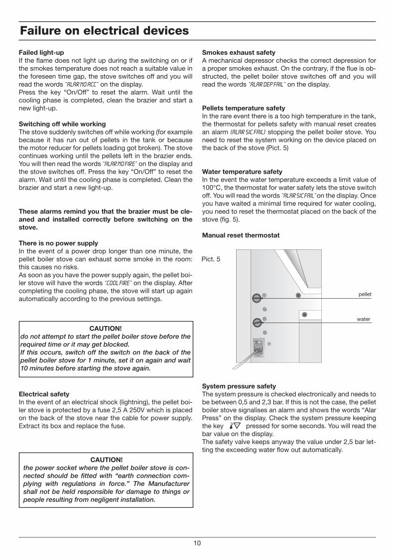
Failed light-upIf the flame does not light up during the switching on or if the smokes temperature does not reach a suitable value in the foreseen time gap, the stove switches off and you will read the words “Alar No Acc” on the display.Press the key “On/Off” to reset the alarm. Wait until the cooling phase is completed, clean the brazier and start a new light-up.
Switching off while workingThe stove suddenly switches off while working (for example because it has run out of pellets in the tank or because the motor reducer for pellets loading got broken). The stove continues working until the pellets left in the brazier ends. You will then read the words “Alar No Fire” on the display and the stove switches off. Press the key “On/Off” to reset the alarm. Wait until the cooling phase is completed. Clean the brazier and start a new light-up.
These alarms remind you that the brazier must be cle-aned and installed correctly before switching on the stove.
There is no power supplyIn the event of a power drop longer than one minute, the pellet boiler stove can exhaust some smoke in the room: this causes no risks.As soon as you have the power supply again, the pellet boi-ler stove will have the words “Cool Fire” on the display. After completing the cooling phase, the stove will start up again automatically according to the previous settings.
Electrical safetyIn the event of an electrical shock (lightning), the pellet boi-ler stove is protected by a fuse 2,5 A 250V which is placed on the back of the stove near the cable for power supply. Extract its box and replace the fuse.
pellet
water
Pict. 5
Failure on electrical devices
10
Smokes exhaust safetyA mechanical depressor checks the correct depression for a proper smokes exhaust. On the contrary, if the flue is ob-structed, the pellet boiler stove switches off and you will read the words “Alar Dep Fail” on the display.
Pellets temperature safetyIn the rare event there is a too high temperature in the tank, the thermostat for pellets safety with manual reset creates an alarm (Alar Sic Fail) stopping the pellet boiler stove. You need to reset the system working on the device placed on the back of the stove (Pict. 5)
Water temperature safetyIn the event the water temperature exceeds a limit value of 100°C, the thermostat for water safety lets the stove switch off. You will read the words “Alar Sic Fail” on the display. Once you have waited a minimal time required for water cooling, you need to reset the thermostat placed on the back of the stove (fig. 5).
Manual reset thermostat
System pressure safetyThe system pressure is checked electronically and needs to be between 0,5 and 2,3 bar. If this is not the case, the pellet boiler stove signalises an alarm and shows the words “Alar Press” on the display. Check the system pressure keeping the key pressed for some seconds. You will read the bar value on the display.The safety valve keeps anyway the value under 2,5 bar let-ting the exceeding water flow out automatically.
CAUTION!do not attempt to start the pellet boiler stove before the required time or it may get blocked.If this occurs, switch off the switch on the back of the pellet boiler stove for 1 minute, set it on again and wait 10 minutes before starting the stove again.
CAUTION!the power socket where the pellet boiler stove is con-nected should be fitted with “earth connection com-plying with regulations in force.” The Manufacturer shall not be held responsible for damage to things or people resulting from negligent installation.
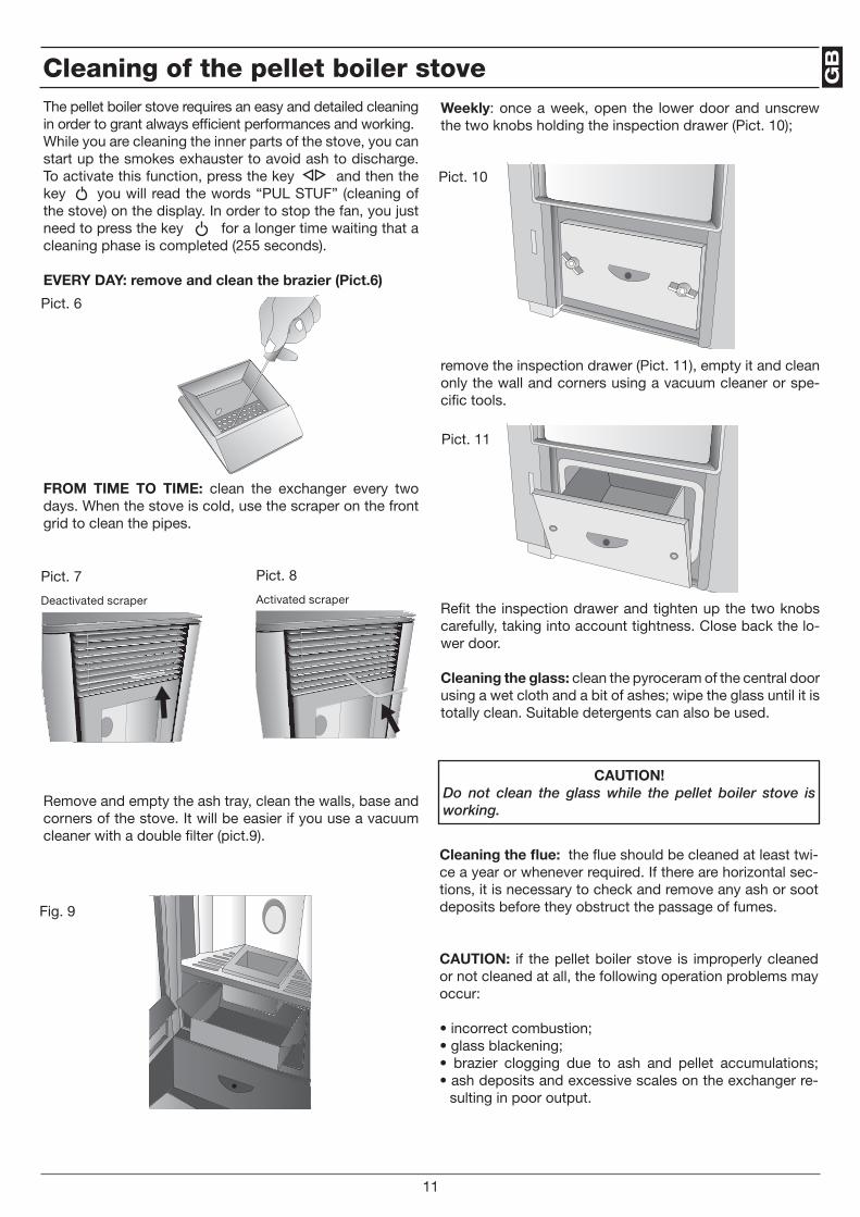
GB
Weekly: once a week, open the lower door and unscrew the two knobs holding the inspection drawer (Pict. 10);
remove the inspection drawer (Pict. 11), empty it and clean only the wall and corners using a vacuum cleaner or spe-cific tools.
Refit the inspection drawer and tighten up the two knobs carefully, taking into account tightness. Close back the lo-wer door.
Cleaning the glass: clean the pyroceram of the central door using a wet cloth and a bit of ashes; wipe the glass until it is totally clean. Suitable detergents can also be used.
Pict. 10
Pict. 11
Cleaning of the pellet boiler stove
11
The pellet boiler stove requires an easy and detailed cleaning in order to grant always efficient performances and working.While you are cleaning the inner parts of the stove, you can start up the smokes exhauster to avoid ash to discharge. To activate this function, press the key and then the key you will read the words “PUL STUF” (cleaning of the stove) on the display. In order to stop the fan, you just need to press the key for a longer time waiting that a cleaning phase is completed (255 seconds).
EvERY DAY: remove and clean the brazier (Pict.6)
FROM TIME TO TIME: clean the exchanger every two days. When the stove is cold, use the scraper on the front grid to clean the pipes.
Remove and empty the ash tray, clean the walls, base and corners of the stove. It will be easier if you use a vacuum cleaner with a double filter (pict.9).
Pict. 6
Pict. 7
Deactivated scraper
Pict. 8
Activated scraper
Fig. 9
Cleaning the flue: the flue should be cleaned at least twi-ce a year or whenever required. If there are horizontal sec-tions, it is necessary to check and remove any ash or soot deposits before they obstruct the passage of fumes.
CAUTION: if the pellet boiler stove is improperly cleaned or not cleaned at all, the following operation problems may occur:
• incorrect combustion;• glass blackening;• brazier clogging due to ash and pellet accumulations;• ash deposits and excessive scales on the exchanger re-
sulting in poor output.
CAUTION!Do not clean the glass while the pellet boiler stove is working.
NOTE
12
Cod
. 001
041
CAUTION!These operations should be carried out by qualified personnel, or by the user, who shall be held responsible in case of damage during maintenance operations. Carry out maintenance operations when the pellet boiler stove is cold and not powered. Maintenance operations carried out by an authorised assistance centre shall be at the customer’s expense.
Extraordinary maintenance
D
23
ACHTUNG!Die Dämpfe des Lackes von Ihrem Warmwasserpelletofen können während der ersten zwei oder drei Einschaltun-gen einen Gestank verursachen. Es ist besser, den Raum zu lüften. Bitte vermeiden Sie eine zu lange Zeit vor dem
Ofen zu verbringen.
Lieber Kunde,Wir freuen uns, dass Sie einen Thermo-Ofen gekauft haben und möchten Sie dabei erinnern, dass dieser Pellets-Thermo-Ofen die neueste Erwärmungs-Lösung darstellt, Frucht der fortschrittlichsten Technologie, bei einem sehr hohen Niveau an Bearbeitungs-Qualität und von einfachen und eleganten Design, welches sich gut and jede Umgebung anpasst, und diese gemütlich macht, dank auch seiner umwickelnden Wärme, welche nur eine wahre Flamme geben kann.Dieses Handbuch wird Ihnen helfen, Euer Thermo-Ofen korrekt zu bedienen. Wir empfehlen Ihnen, deshalb, es genau vor dem Gebrauch zu lesen.
Die Errichtung muss von qualifiziertem Personal ausgeführt werden, welches die ganze Verantwortung für die definitive Errichtung und für das gute Funktionieren des errichteten Produktes trägt. Es wird keine Verantwortung seitens des Herstellers anerkannt im Falle einer Installierung seitens nicht qualifizierten Personal sowie im Falle von Nichtbefolgung der allgemeinen Anmerkungen und der Installierungs-Hinweisen.
Wenn man die Verpackung bereits entfernt hat, muss man die Vollständigkeit des Inhaltes nachprüfen; im Falle von Män-geln, muss man sich zu dem Verkäufer wenden, bei dem der Thermo-Ofen gekauft wurde. Vor der Installierung wird es empfohlen, alle Röhre der Anlage gründlich zu reinigen somit eventuelle Reste zu entfernen, welche das gute Funktionie-ren der Anlage beeinträchtigen könnten.Im Fall einer Nichtbenützung des Thermo-Ofens für längere Zeit, wird es empfohlen folgende Operationen auszuführen:• den Stecker der elektrischen Speisung ausziehen;• die Wasserhahne des Wassers von der thermischen Anlage und der sanitärischen Anlage schließen;• wenn es Frost-Gefahr gibt, die thermische und sanitärische Anlage ausleeren.Die außerordentliche Instandsetzung des Thermo-Ofens, muss mindestens Einmal im Jahre ausgeführt werden. Diese In-standsetzung muss zeitlich mit dem technischen Kundendienst programmiert werden, und geht zu Lasten des Kunden.
Für die Sicherheit, ist es gut sich zu erinnern, dass:
• Es nicht empfohlen ist, den Thermo-Ofen von Kindern oder von unbeholfenen, behinderten Personen benutzen zu lassen;• den Thermo-Ofen nicht berühren wenn man barfuss ist, oder wenn man teilweise nass ist;• es ist verboten die Sicherheits- oder die Regulierungs-Systeme zu verändern, ohne Ermächtigung oder Angaben des Her-stellers;
• die elektrischen Kabeln, welche aus dem Kessel herausragen, nicht ziehen, entfernen, verdrehen, auch wenn dieser nicht mit dem Stromnetz verbunden ist;
• man vermeide, Luft-Leitungen zu stopfen oder zu verkleinern, diese sind notwendig für eine korrekte Verbrennung;• die Elemente der Verpackung sollten nicht von Kindern oder von unfähigen Personen angefasst werden.
Im Fall von Feuer, schalten Sie die Stromversorgung aus, benützen Sie einen Feuerlöscher und rufen Sie die Feuerwehr an, wenn notwendig. Danach rufen Sie ein autorisiertes Assistenzzentrum an.
Die Thermo-Ofen, nur funktionierend mit Holz-Pellets von 6 mm Maximaler Durchmesser, sind mit einem Wärme-Austauscher ausgerüstet, welcher eine Rückgabe von etwa 90% der Wärme ermöglicht. Die Thermo-Öfen sind mit einem Chronothermo-stat ausgestattet, welches bis zu 4 wöchentlichen Anzündungen und 4 Löschungen garantiert. Damit wird der Betrieb ganz unabhängig. Die Thermo-Ofen bringen die Wärme an die Heizkörper Ihrer Anlage bei einer thermischen Leistung, welche sich selbstständig in Funktion der Umgebung zu wärmen reguliert: es genügt die Wasser-Temperatur der Wärme-Anlage manuell zu regulieren, welche als 60-75° empfohlen wird.Die Thermo-Ofen sind auch mit einem tangentialen Ventilator ausgestattet, für die Verbreitung von warmen Luft, welche die Erwärmung ermöglicht durch erzwungene Konvektion des Raumes, wo sie installiert wird.Dank einem optionalen Kit, produzieren diese auch ständig warmes sanitärisches Wasser in sicherer und gesunder Weise, durch automatische Funktionierung, ohne Aufspeicherungs-Bedarf.Die Thermo-Öfen sind mit hochmodernen Automatismen sowie Kontroll-Systemen und Sicherheiten ausgerüstet, welche ihnen eine praktische und wirksame Funktionalität garantieren.Die Errichtung und die Instandsetzung müssen von qualifiziertem Personal ausgeführt werden, gemäß den bestehenden Gesetzen und nach den Angaben des Herstellers. Dieses Gebrauchs- und Instandsetzungs-Handbuch ist ein integrierter Teil des Produktes. Vor der Errichtung, dem Gebrauch und der Instandsetzung des Produktes, muss man aufmerksam die Angaben lesen, welche in diesem Handbuch enthalten sind. Dieser Thermo-Ofen muss nur für den Gebrauch für den er realisiert wurde, benutzt werden. Aus diesem Grunde, jede Verantwortung für eventuelle Schäden an Personen, Tieren oder Sachen infolge einen falschen Gebrauches des Produktes wird zu dem Benutzer angelastet.
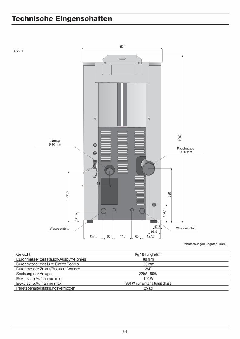
Technische Eingenschaften
Kg 184 unghefähr80 mm 50 mm
3/4” 220V - 50Hz
140 W350 W nur Einschaltungsphase
25 kg
Gewicht Durchmesser des Rauch-Auspuff-RohresDurchmesser des Luft-Eintritt RohresDurchmesser Zulauf/Rücklauf Wasser Speisung der AnlageElektrische Aufnahme min.Elektrische Aufnahme maxPelletsbehältersfassungsvermögen
Abb. 1
24
47,5
99,5127,5 65 115 65 127,5
168
102,
5
358,
5
134,
5
390
1080
534
LuftzugØ 50 mm
RauchabzugØ 80 mm
WasseraustrittWassereintritt
Abmessungen ungefähr (mm).
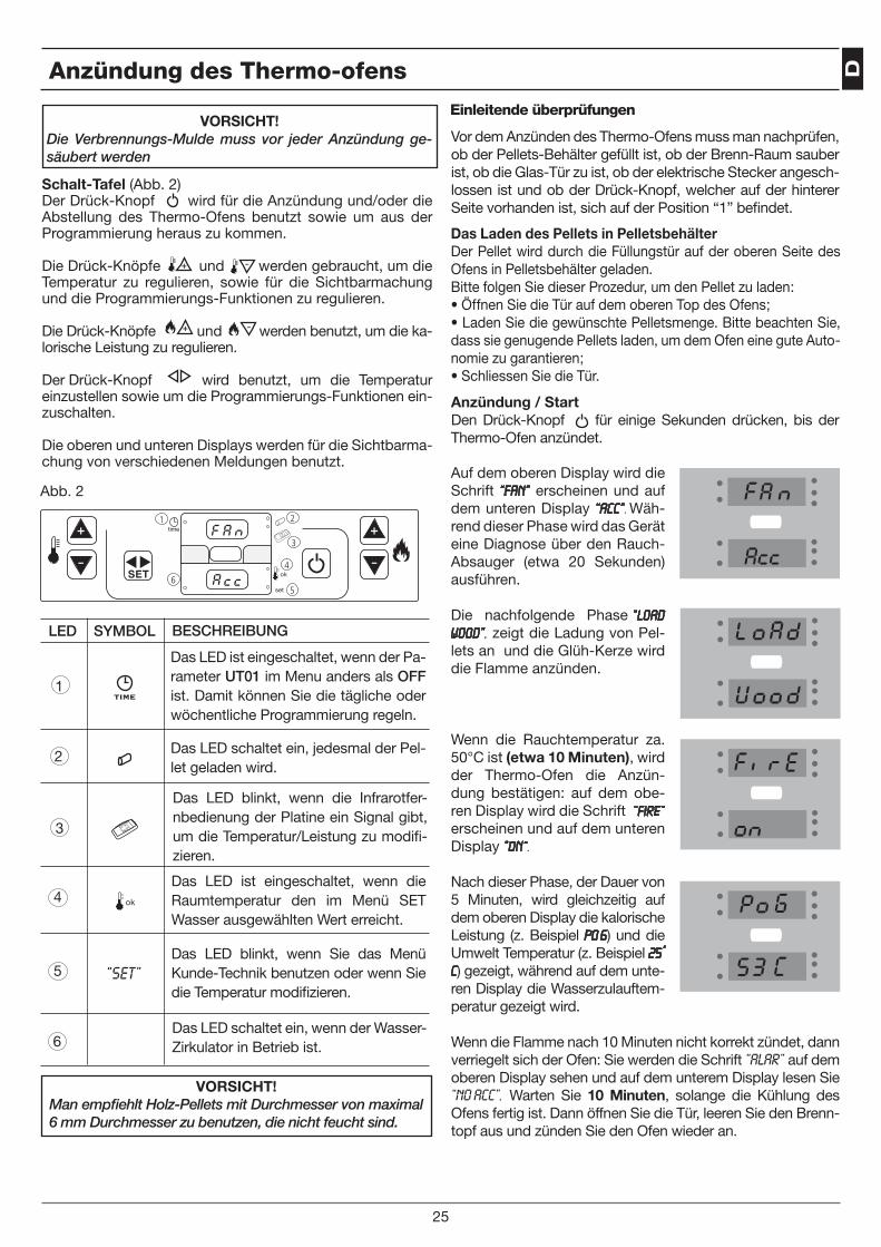
D
Anzündung / StartDen Drück-Knopf für einige Sekunden drücken, bis der Thermo-Ofen anzündet.
Anzündung des Thermo-ofens
VORSICHT! Die Verbrennungs-Mulde muss vor jeder Anzündung ge-säubert werden
Vor dem Anzünden des Thermo-Ofens muss man nachprüfen, ob der Pellets-Behälter gefüllt ist, ob der Brenn-Raum sauber ist, ob die Glas-Tür zu ist, ob der elektrische Stecker angesch-lossen ist und ob der Drück-Knopf, welcher auf der hinterer Seite vorhanden ist, sich auf der Position “1” befindet.
Das LED ist eingeschaltet, wenn der Pa-rameter UT01 im Menu anders als OFF ist. Damit können Sie die tägliche oder wöchentliche Programmierung regeln.
Auf dem oberen Display wird die Schrift “Fan” erscheinen und auf dem unteren Display “ACC”. Wäh-rend dieser Phase wird das Gerät eine Diagnose über den Rauch-Absauger (etwa 20 Sekunden) ausführen.
Die nachfolgende Phase “LOAD WOOD”, zeigt die Ladung von Pel-lets an und die Glüh-Kerze wird die Flamme anzünden.
Wenn die Rauchtemperatur za. 50°C ist (etwa 10 Minuten), wird der Thermo-Ofen die Anzün-dung bestätigen: auf dem obe-ren Display wird die Schrift “Fire” erscheinen und auf dem unteren Display “On”.
Nach dieser Phase, der Dauer von 5 Minuten, wird gleichzeitig auf dem oberen Display die kalorische Leistung (z. Beispiel po 6) und die Umwelt Temperatur (z. Beispiel 25° C) gezeigt, während auf dem unte-ren Display die Wasserzulauftem-peratur gezeigt wird.
Wenn die Flamme nach 10 Minuten nicht korrekt zündet, dann verriegelt sich der Ofen: Sie werden die Schrift “ALAR” auf dem oberen Display sehen und auf dem unterem Display lesen Sie “NO ACC”. Warten Sie 10 Minuten, solange die Kühlung des Ofens fertig ist. Dann öffnen Sie die Tür, leeren Sie den Brenn-topf aus und zünden Sie den Ofen wieder an.
Abb. 2
Einleitende überprüfungen
25
6
1 2
3
4
5
“SET”
LED SYMBOL BESCHREIBUNG
1
2
3
4
5
6
Das LED schaltet ein, jedesmal der Pel-let geladen wird.
Das LED blinkt, wenn die Infrarotfer-nbedienung der Platine ein Signal gibt, um die Temperatur/Leistung zu modifi-zieren.
Das LED ist eingeschaltet, wenn die Raumtemperatur den im Menü SET Wasser ausgewählten Wert erreicht.
Das LED blinkt, wenn Sie das Menü Kunde-Technik benutzen oder wenn Sie die Temperatur modifizieren.
Das LED schaltet ein, wenn der Wasser-Zirkulator in Betrieb ist.
Das Laden des Pellets in PelletsbehälterDer Pellet wird durch die Füllungstür auf der oberen Seite des Ofens in Pelletsbehälter geladen.Bitte folgen Sie dieser Prozedur, um den Pellet zu laden:• Öffnen Sie die Tür auf dem oberen Top des Ofens;• Laden Sie die gewünschte Pelletsmenge. Bitte beachten Sie, dass sie genugende Pellets laden, um dem Ofen eine gute Auto-nomie zu garantieren;• Schliessen Sie die Tür.
Schalt-Tafel (Abb. 2)Der Drück-Knopf wird für die Anzündung und/oder die Abstellung des Thermo-Ofens benutzt sowie um aus der Programmierung heraus zu kommen.
Die Drück-Knöpfe und werden gebraucht, um die Temperatur zu regulieren, sowie für die Sichtbarmachung und die Programmierungs-Funktionen zu regulieren.
Die Drück-Knöpfe und werden benutzt, um die ka-lorische Leistung zu regulieren.
Der Drück-Knopf wird benutzt, um die Temperatur einzustellen sowie um die Programmierungs-Funktionen ein-zuschalten.
Die oberen und unteren Displays werden für die Sichtbarma-chung von verschiedenen Meldungen benutzt.
VORSICHT!Man empfiehlt Holz-Pellets mit Durchmesser von maximal 6 mm Durchmesser zu benutzen, die nicht feucht sind.
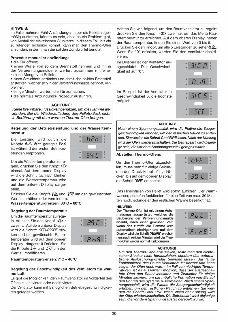
Um den Thermo-Ofen abzustel-len, muss man für einige Sekun-den den Druck-knopf , drü-cken, bis auf dem oberen Display die Schrift “OFF” erscheint.
HINWEIS:Im Falle mehrerer Fehl-Anzündungen, aber die Pellets regel-mäßig austreten, könnte es sein, dass es ein Problem gibt, von Ausfall der elektrischen Glühkerze. In diesem Fall, bis ein zu rufender Techniker kommt, kann man den Thermo-Ofen anzünden, in dem man die soliden Zündwürfel benutzt.
Prozedur manueller anzündung:• die Tür öffnen;• einen Würfel von solidem Brennstoff nehmen und ihn in der Verbrennungsmulde einwerfen, zusammen mit einer kleinen Menge von Pellets;• einen Streichholz anzünden und damit den soliden Brennstoff anstecken, welcher sich in der Verbrennungsmulde befindet, ver-brennen;• einige Minuten warten, die Tür zumachen;• die normale Anzündungs-Prozedur ausführen.
Regelung der Betriebsleistung und der Wassertem-peratur
Regelung der Raumtemperatur
Um die Raumtemperatur zu rege-ln, drücken Sie den Knopf : zweimal. Auf dem unteren Display wird die Schrift “SET WASSER” blin-ken und die gewünschte Raum-temperatur wird auf dem oberen Display dargestellt.Drücken Sie die Knöpfe und um den Wert zu modifizieren.
Drücken Sie die Knöpfe und um den gewünschten Wert zu erhöhen oder vermindern.Wassertemperaturgrenzen: 30°C – 80°C
Abstellen Thermo-Ofens
Das Hineinfallen von Pellet wird sofort aufhören. Der Warm-wasserpelletofen funktioniert für eine Zeit von max. 30 Minu-ten noch, solange er den restlichen Wärme beseitigt hat.
ACHTUNG! Nach einem Spannungsausfall, wird die Platine die Sauger-geschwindigkeit erhöhen, um den restlichen Rauch zu entfer-nen. Sie werden die Schrift Cool FIRE lesen. Nach der Kühlung wird der Ofen wiedereinschalten. Die Betriebsart wird diejeni-ge sein, die vor dem Spannungsausfall geregelt wurde.
Die Leistung wird durch die Knöpfe geregelt. Po 9 ist während der ersten Betriebs-stunden empfohlen.
Um die Wassertemperatur zu re-geln, drücken Sie den Knopf einmal. Auf dem oberen Display wird die Schrift “Set H2o” blinken und die Wassertemperatur wird auf dem unteren Display darge-stellt.
HINWEIS:Der Thermo-Ofen ist mit einem Auto-matismus ausgerüstet, welches die Säuberung der Verbrennungsmulde erlaubt, nach einer gewissen Zeit: wenn das zutrifft, die Flamme wird automatisch niedriger und auf dem Display wird die Schrift “PUL FIRE” erschei-nen; nach einigen Minuten wird der Ther-mo-Ofen wieder normal funktionieren.
26
Raumtemperaturgrenzen: 7°C – 40°C
Regelung der Geschwindigkeit des Ventilators für war-me LuftEs gibt die Möglichkeit, den Raumventilator im Vorderteil des Ofens zu aktivieren oder deaktivieren.Der Ventilator kann mit 5 möglichen Betriebsgeschwindigkei-ten geregelt werden.
Achten Sie wie folgend, um den Raumventilator zu regeln: drücken Sie den Knopf zweimal, um das Menü Rau-mtemperatur zu erreichen. Auf dem oberen Display, neben der Raumtemperatur, finden Sie einen Wert von 0 bis 5.Drücken Sie den Knopf, um alle 5 Leistungen zu sehen . Wenn Sie “0” drücken, werden Sie den Ventilator deakti-vieren.
Im Beispiel ist der Ventilator au-sgeschlatet. Die Geschwindi-gkeit ist auf “0”.
Im Beispiel ist der Ventilator in Geschwindigkeit 5, die höchste möglich.
ACHTUNG!Um den Thermo-Ofen abzustellen, sollte man den elektri-schen Stecker nicht herausziehen, sondern das automa-tische Auslöschungs-Zyklus beenden lassen: das lange Funktionieren des Rauch Ventilators ist normal und kann zeigen der Ofen noch warm. Im Fall von niedrigen Tempe-raturen, ist es ausserdem möglich, dass der ausgeschal-tete Ofen den Rauchventilator und Zirkulator für einige Minuten aktiviert, um die mögliche Formation von Eis auf den Rohren des Systems zu vermeiden. Nach einem Span-nungsausfall, wird die Platine die Saugergeschwindigkeit erhöhen, um den restlichen Rauch zu entfernen. Sie wer-den die Schrift Cool FIRE lesen. Nach der Kühlung wird der Ofen wiedereinschalten. Die Betriebsart wird diejenige sein, die vor dem Spannungsausfall geregelt wurde.
ACHTUNG!Keine brennbare Flüssigkeit benutzen, um die Flamme an-zünden. Bei der Wiederaufladung den Pellets-Sack nicht in Berührung mit dem warmen Thermo-Ofen bringen.
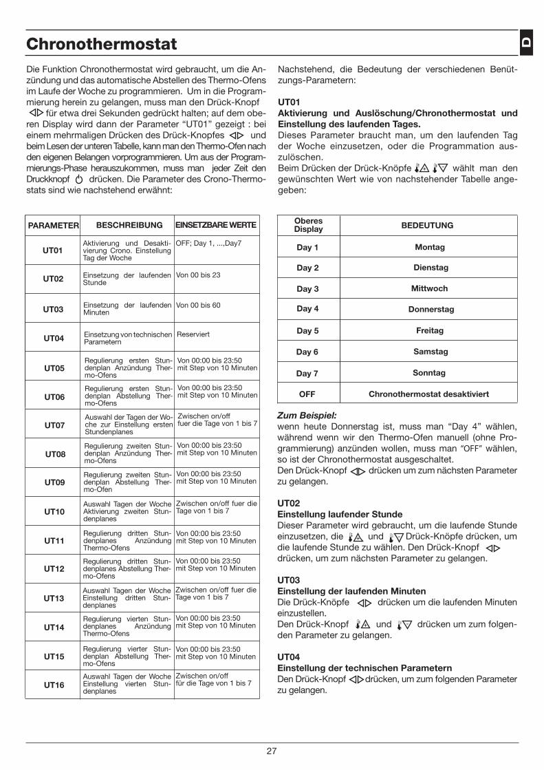
D
27
Chronothermostat
UT01
UT02
UT03
UT04
UT05
UT06
UT07
UT08
UT09
UT10
UT11
UT12
UT13
UT14
UT15
UT16
Nachstehend, die Bedeutung der verschiedenen Benüt-zungs-Parametern:
UT01 Aktivierung und Auslöschung/Chronothermostat und Einstellung des laufenden Tages.Dieses Parameter braucht man, um den laufenden Tag der Woche einzusetzen, oder die Programmation aus-zulöschen.Beim Drücken der Drück-Knöpfe wählt man den gewünschten Wert wie von nachstehender Tabelle ange-geben:
OberesDisplay BEDEUTUNG
Day 1
Day 2
Day 3
Day 4
Day 5
Day 6
Day 7
OFF
Die Funktion Chronothermostat wird gebraucht, um die An-zündung und das automatische Abstellen des Thermo-Ofens im Laufe der Woche zu programmieren. Um in die Program-mierung herein zu gelangen, muss man den Drück-Knopf für etwa drei Sekunden gedrückt halten; auf dem obe-ren Display wird dann der Parameter “UT01” gezeigt : bei einem mehrmaligen Drücken des Drück-Knopfes und beim Lesen der unteren Tabelle, kann man den Thermo-Ofen nach den eigenen Belangen vorprogrammieren. Um aus der Program-mierungs-Phase herauszukommen, muss man jeder Zeit den Druckknopf drücken. Die Parameter des Crono-Thermo-stats sind wie nachstehend erwähnt:
Montag
Dienstag
Mittwoch
Donnerstag
Freitag
Samstag
Sonntag
Chronothermostat desaktiviert
Zum Beispiel: wenn heute Donnerstag ist, muss man “Day 4” wählen, während wenn wir den Thermo-Ofen manuell (ohne Pro-grammierung) anzünden wollen, muss man “OFF” wählen, so ist der Chronothermostat ausgeschaltet.Den Drück-Knopf drücken um zum nächsten Parameter zu gelangen.
UT02 Einstellung laufender StundeDieser Parameter wird gebraucht, um die laufende Stunde einzusetzen, die und Drück-Knöpfe drücken, um die laufende Stunde zu wählen. Den Drück-Knopf drücken, um zum nächsten Parameter zu gelangen.
UT03Einstellung der laufenden MinutenDie Drück-Knöpfe drücken um die laufenden Minuten einzustellen.Den Drück-Knopf und drücken um zum folgen-den Parameter zu gelangen.
UT04Einstellung der technischen ParameternDen Drück-Knopf drücken, um zum folgenden Parameter zu gelangen.
PARAMETER BESCHREIBUNG EINSETZBARE WERTE
OFF; Day 1, ...,Day7Aktivierung und Desakti-vierung Crono. Einstellung Tag der Woche
Von 00 bis 23Einsetzung der laufenden Stunde
Von 00 bis 60Einsetzung der laufenden Minuten
ReserviertEinsetzung von technischen Parametern
Von 00:00 bis 23:50mit Step von 10 Minuten
Regulierung ersten Stun-denplan Anzündung Ther-mo-Ofens
Von 00:00 bis 23:50mit Step von 10 Minuten
Regulierung ersten Stun-denplan Abstellung Ther-mo-Ofens
Zwischen on/offfuer die Tage von 1 bis 7
Auswahl der Tagen der Wo-che zur Einstellung ersten Stundenplanes
Von 00:00 bis 23:50mit Step von 10 Minuten
Regulierung zweiten Stun-denplan Anzündung Ther-mo-Ofens
Von 00:00 bis 23:50mit Step von 10 Minuten
Regulierung zweiten Stun-denplan Abstellung Ther-mo-Ofen
Zwischen on/off fuer die Tage von 1 bis 7
Auswahl Tagen der Woche Aktivierung zweiten Stun-denplanes
Von 00:00 bis 23:50mit Step von 10 Minuten
Regulierung dritten Stun-denplanes Anzündung Thermo-Ofens
Von 00:00 bis 23:50mit Step von 10 Minuten
Regulierung dritten Stun-denplanes Abstellung Ther-mo-Ofens
Zwischen on/off fuer die Tage von 1 bis 7
Auswahl Tagen der Woche Einstellung dritten Stun-denplanes
Von 00:00 bis 23:50mit Step von 10 Minuten
Regulierung vierten Stun-denplanes Anzündung Thermo-Ofens
Von 00:00 bis 23:50mit Step von 10 Minuten
Regulierung vierter Stun-denplan Abstellung Ther-mo-Ofens
Zwischen on/off für die Tage von 1 bis 7
Auswahl Tagen der Woche Einstellung vierten Stun-denplanes
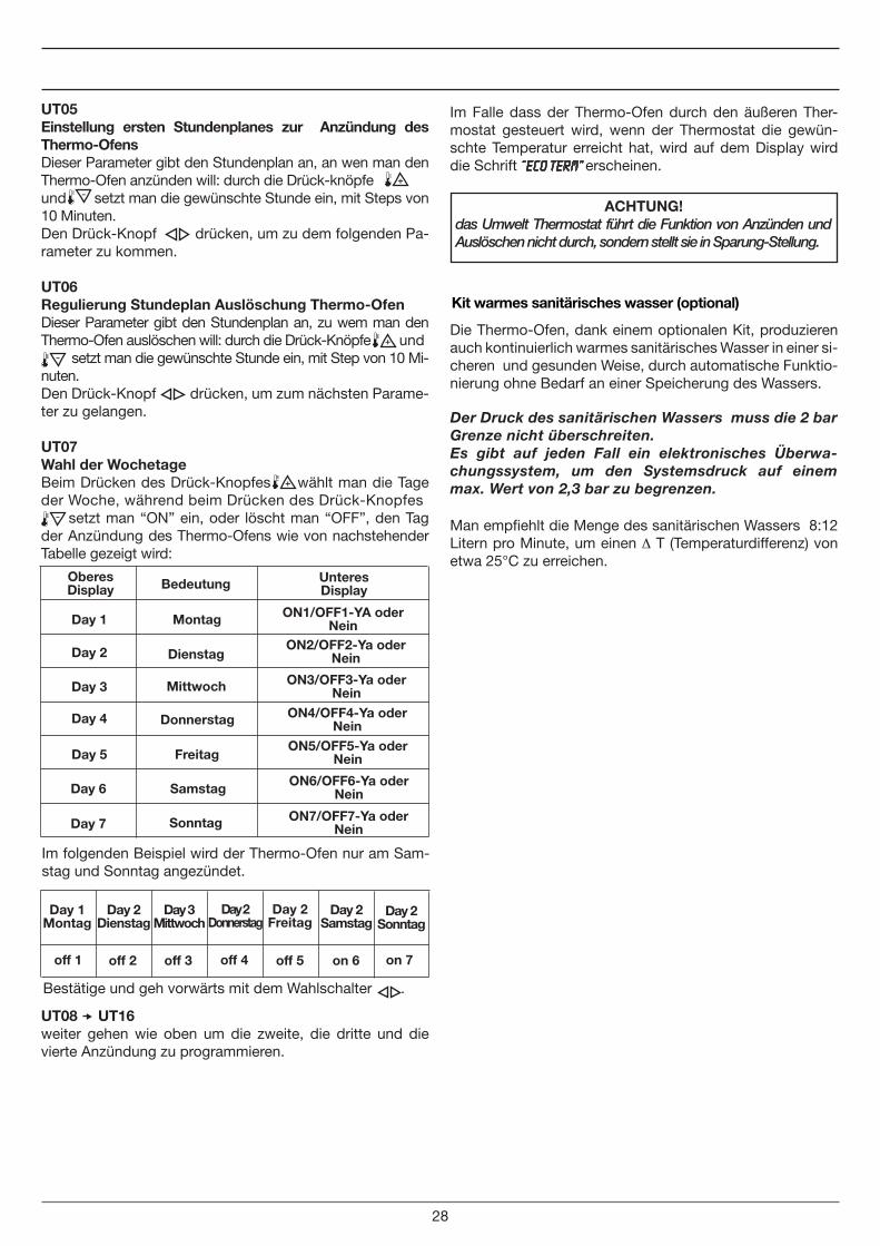
28
Im Falle dass der Thermo-Ofen durch den äußeren Ther-mostat gesteuert wird, wenn der Thermostat die gewün-schte Temperatur erreicht hat, wird auf dem Display wird die Schrift “ECO TERM” erscheinen.
ACHTUNG!das Umwelt Thermostat führt die Funktion von Anzünden und Auslöschen nicht durch, sondern stellt sie in Sparung-Stellung.
UT08 UT16 weiter gehen wie oben um die zweite, die dritte und die vierte Anzündung zu programmieren.
Kit warmes sanitärisches wasser (optional)
Die Thermo-Ofen, dank einem optionalen Kit, produzieren auch kontinuierlich warmes sanitärisches Wasser in einer si-cheren und gesunden Weise, durch automatische Funktio-nierung ohne Bedarf an einer Speicherung des Wassers.
Man empfiehlt die Menge des sanitärischen Wassers 8:12 Litern pro Minute, um einen ∆ T (Temperaturdifferenz) von etwa 25°C zu erreichen.
UT05Einstellung ersten Stundenplanes zur Anzündung des Thermo-OfensDieser Parameter gibt den Stundenplan an, an wen man den Thermo-Ofen anzünden will: durch die Drück-knöpfe und setzt man die gewünschte Stunde ein, mit Steps von 10 Minuten.Den Drück-Knopf drücken, um zu dem folgenden Pa-rameter zu kommen.
UT06Regulierung Stundeplan Auslöschung Thermo-OfenDieser Parameter gibt den Stundenplan an, zu wem man den Thermo-Ofen auslöschen will: durch die Drück-Knöpfe und setzt man die gewünschte Stunde ein, mit Step von 10 Mi-nuten. Den Drück-Knopf drücken, um zum nächsten Parame-ter zu gelangen.
UT07Wahl der WochetageBeim Drücken des Drück-Knopfes wählt man die Tage der Woche, während beim Drücken des Drück-Knopfes setzt man “ON” ein, oder löscht man “OFF”, den Tag der Anzündung des Thermo-Ofens wie von nachstehender Tabelle gezeigt wird:
Der Druck des sanitärischen Wassers muss die 2 bar Grenze nicht überschreiten.Es gibt auf jeden Fall ein elektronisches Überwa-chungssystem, um den Systemsdruck auf einem max. Wert von 2,3 bar zu begrenzen.
Im folgenden Beispiel wird der Thermo-Ofen nur am Sam-stag und Sonntag angezündet.
Bestätige und geh vorwärts mit dem Wahlschalter .
OberesDisplay Bedeutung
Day 1
Day 2
Day 3
Day 4
Day 5
Day 6
Day 7
Montag
Dienstag
Mittwoch
Donnerstag
Freitag
Samstag
Sonntag
UnteresDisplay
ON1/OFF1-YA oder Nein
ON2/OFF2-Ya oder Nein
ON3/OFF3-Ya oder Nein
ON4/OFF4-Ya oder Nein
ON5/OFF5-Ya oder Nein
ON6/OFF6-Ya oder Nein
ON7/OFF7-Ya oder Nein
Day 1 Montag
off 1
Day 2 Dienstag
Day 3 Mittwoch
Day 2 Donnerstag
Day 2 Freitag
Day 2 Samstag
Day 2 Sonntag
off 2 off 3 off 4 off 5 on 6 on 7
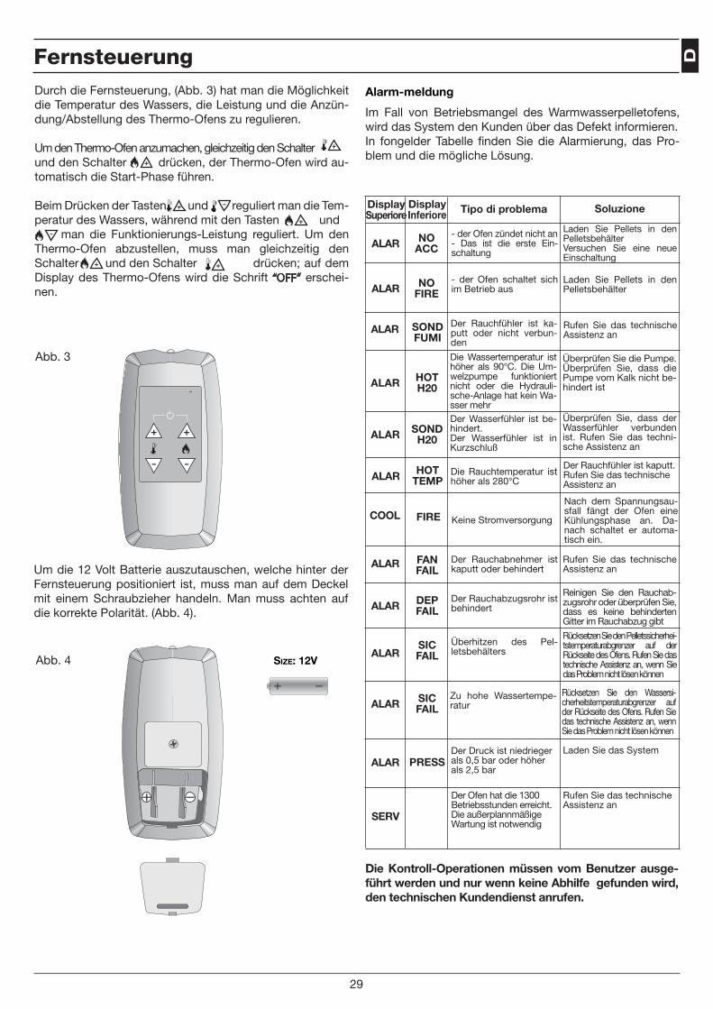
D
Alarm-meldung
Im Fall von Betriebsmangel des Warmwasserpelletofens, wird das System den Kunden über das Defekt informieren.In fongelder Tabelle finden Sie die Alarmierung, das Pro-blem und die mögliche Lösung.
DisplaySuperiore
DisplayInferiore Tipo di problema Soluzione
ALAR FAN FAIL
ALAR DEP FAIL
ALARSIC FAIL
ALAR SIC FAIL
ALAR PRESS
Der Rauchabnehmer ist kaputt oder behindert
Der Rauchabzugsrohr ist behindert
Überhitzen des Pel-letsbehälters
Zu hohe Wassertempe-ratur
Der Druck ist niedrieger als 0,5 bar oder höher als 2,5 bar
Rufen Sie das technische Assistenz an
Reinigen Sie den Rauchab-zugsrohr oder überprüfen Sie, dass es keine behinderten Gitter im Rauchabzug gibt
Rücksetzen Sie den Pelletssicherhei-tstemperaturabgrenzer auf der Rückseite des Ofens. Rufen Sie das technische Assistenz an, wenn Sie das Problem nicht lösen können
Rücksetzen Sie den Wassersi-cherheitstemperaturabgrenzer auf der Rückseite des Ofens. Rufen Sie das technische Assistenz an, wenn Sie das Problem nicht lösen können
Laden Sie das System
ALAR NO ACC
- der Ofen zündet nicht an- Das ist die erste Ein-schaltung
Laden Sie Pellets in den PelletsbehälterVersuchen Sie eine neue Einschaltung
ALAR NO FIRE
- der Ofen schaltet sich im Betrieb aus
Laden Sie Pellets in den Pelletsbehälter
ALAR SOND FUMI
Der Rauchfühler ist ka-putt oder nicht verbun-den
Rufen Sie das technische Assistenz an
ALAR HOT H20
Die Wassertemperatur ist höher als 90°C. Die Um-welzpumpe funktioniert nicht oder die Hydrauli-sche-Anlage hat kein Wa-sser mehr
Überprüfen Sie die Pumpe.Überprüfen Sie, dass die Pumpe vom Kalk nicht be-hindert ist
ALAR SOND H20
Der Wasserfühler ist be-hindert.Der Wasserfühler ist in Kurzschluß
Überprüfen Sie, dass der Wasserfühler verbunden ist. Rufen Sie das techni-sche Assistenz an
ALAR HOT TEMP
Die Rauchtemperatur ist höher als 280°C
Der Rauchfühler ist kaputt.Rufen Sie das technische Assistenz an
COOL FIRE Keine Stromversorgung
Nach dem Spannungsau-sfall fängt der Ofen eine Kühlungsphase an. Da-nach schaltet er automa-tisch ein.
Die Kontroll-Operationen müssen vom Benutzer ausge-führt werden und nur wenn keine Abhilfe gefunden wird, den technischen Kundendienst anrufen.
Fernsteuerung
29
SERV
Der Ofen hat die 1300 Betriebsstunden erreicht. Die außerplannmäßige Wartung ist notwendig
Rufen Sie das technische Assistenz an
Size: 12V
Abb. 3
Abb. 4 Size: 12V
Durch die Fernsteuerung, (Abb. 3) hat man die Möglichkeit die Temperatur des Wassers, die Leistung und die Anzün-dung/Abstellung des Thermo-Ofens zu regulieren.
Um den Thermo-Ofen anzumachen, gleichzeitig den Schalter und den Schalter drücken, der Thermo-Ofen wird au-tomatisch die Start-Phase führen.
Beim Drücken der Tasten und reguliert man die Tem-peratur des Wassers, während mit den Tasten und man die Funktionierungs-Leistung reguliert. Um den Thermo-Ofen abzustellen, muss man gleichzeitig den Schalter und den Schalter drücken; auf dem Display des Thermo-Ofens wird die Schrift “OFF” erschei-nen.
Um die 12 Volt Batterie auszutauschen, welche hinter der Fernsteuerung positioniert ist, muss man auf dem Deckel mit einem Schraubzieher handeln. Man muss achten auf die korrekte Polarität. (Abb. 4).
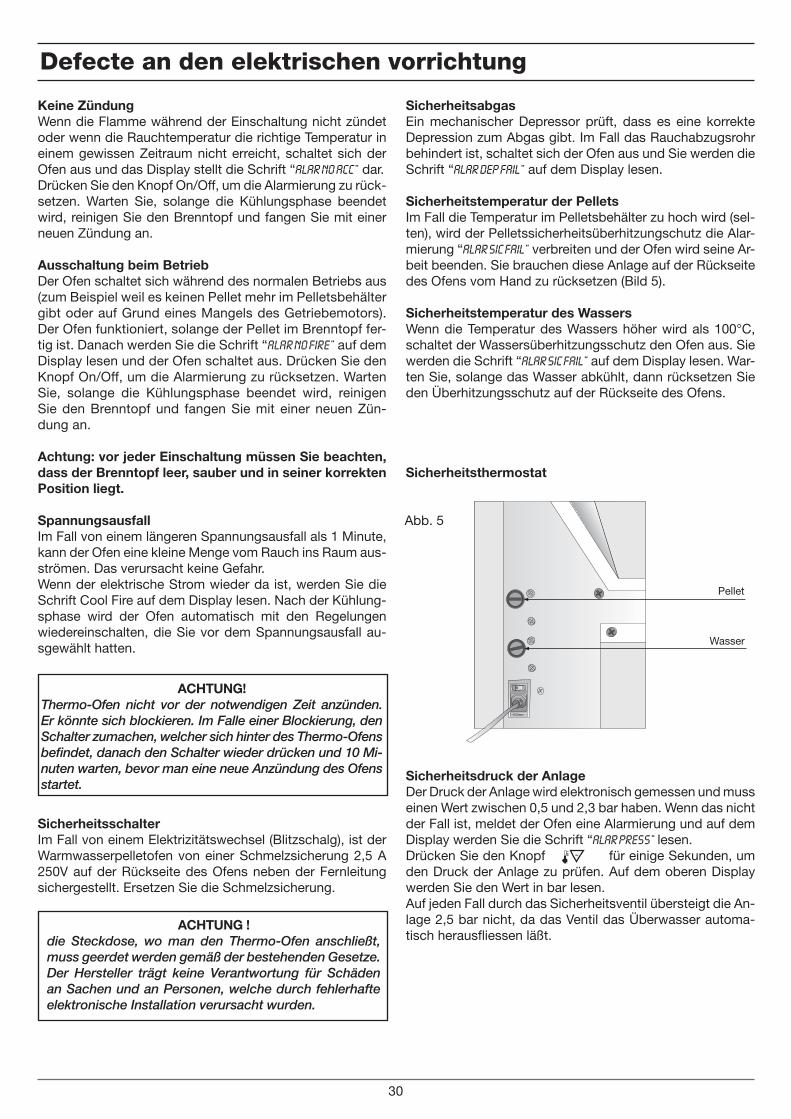
Keine Zündung Wenn die Flamme während der Einschaltung nicht zündet oder wenn die Rauchtemperatur die richtige Temperatur in einem gewissen Zeitraum nicht erreicht, schaltet sich der Ofen aus und das Display stellt die Schrift “Alar No Acc” dar.Drücken Sie den Knopf On/Off, um die Alarmierung zu rück-setzen. Warten Sie, solange die Kühlungsphase beendet wird, reinigen Sie den Brenntopf und fangen Sie mit einer neuen Zündung an.
Ausschaltung beim BetriebDer Ofen schaltet sich während des normalen Betriebs aus (zum Beispiel weil es keinen Pellet mehr im Pelletsbehälter gibt oder auf Grund eines Mangels des Getriebemotors). Der Ofen funktioniert, solange der Pellet im Brenntopf fer-tig ist. Danach werden Sie die Schrift “Alar No Fire” auf dem Display lesen und der Ofen schaltet aus. Drücken Sie den Knopf On/Off, um die Alarmierung zu rücksetzen. Warten Sie, solange die Kühlungsphase beendet wird, reinigen Sie den Brenntopf und fangen Sie mit einer neuen Zün-dung an.
Achtung: vor jeder Einschaltung müssen Sie beachten, dass der Brenntopf leer, sauber und in seiner korrekten Position liegt.
SpannungsausfallIm Fall von einem längeren Spannungsausfall als 1 Minute, kann der Ofen eine kleine Menge vom Rauch ins Raum aus-strömen. Das verursacht keine Gefahr.Wenn der elektrische Strom wieder da ist, werden Sie die Schrift Cool Fire auf dem Display lesen. Nach der Kühlung-sphase wird der Ofen automatisch mit den Regelungen wiedereinschalten, die Sie vor dem Spannungsausfall au-sgewählt hatten.
Sicherheitsschalter Im Fall von einem Elektrizitätswechsel (Blitzschalg), ist der Warmwasserpelletofen von einer Schmelzsicherung 2,5 A 250V auf der Rückseite des Ofens neben der Fernleitung sichergestellt. Ersetzen Sie die Schmelzsicherung.
Pellet
Wasser
Abb. 5
Defecte an den elektrischen vorrichtung
30
SicherheitsabgasEin mechanischer Depressor prüft, dass es eine korrekte Depression zum Abgas gibt. Im Fall das Rauchabzugsrohr behindert ist, schaltet sich der Ofen aus und Sie werden die Schrift “Alar Dep Fail” auf dem Display lesen.
Sicherheitstemperatur der PelletsIm Fall die Temperatur im Pelletsbehälter zu hoch wird (sel-ten), wird der Pelletssicherheitsüberhitzungschutz die Alar-mierung “Alar Sic Fail” verbreiten und der Ofen wird seine Ar-beit beenden. Sie brauchen diese Anlage auf der Rückseite des Ofens vom Hand zu rücksetzen (Bild 5).
Sicherheitstemperatur des WassersWenn die Temperatur des Wassers höher wird als 100°C, schaltet der Wassersüberhitzungsschutz den Ofen aus. Sie werden die Schrift “Alar Sic Fail” auf dem Display lesen. War-ten Sie, solange das Wasser abkühlt, dann rücksetzen Sie den Überhitzungsschutz auf der Rückseite des Ofens.
Sicherheitsthermostat
Sicherheitsdruck der AnlageDer Druck der Anlage wird elektronisch gemessen und muss einen Wert zwischen 0,5 und 2,3 bar haben. Wenn das nicht der Fall ist, meldet der Ofen eine Alarmierung und auf dem Display werden Sie die Schrift “Alar Press” lesen. Drücken Sie den Knopf für einige Sekunden, um den Druck der Anlage zu prüfen. Auf dem oberen Display werden Sie den Wert in bar lesen. Auf jeden Fall durch das Sicherheitsventil übersteigt die An-lage 2,5 bar nicht, da das Ventil das Überwasser automa-tisch herausfliessen läßt.
ACHTUNG!Thermo-Ofen nicht vor der notwendigen Zeit anzünden. Er könnte sich blockieren. Im Falle einer Blockierung, den Schalter zumachen, welcher sich hinter des Thermo-Ofens befindet, danach den Schalter wieder drücken und 10 Mi-nuten warten, bevor man eine neue Anzündung des Ofens startet.
ACHTUNG !die Steckdose, wo man den Thermo-Ofen anschließt, muss geerdet werden gemäß der bestehenden Gesetze. Der Hersteller trägt keine Verantwortung für Schäden an Sachen und an Personen, welche durch fehlerhafte elektronische Installation verursacht wurden.

D
Wöchentlich: einmal in der Woche, die untere Tür öffnen und die zwei Kugelgriffe welche den Ispektions-Kasten hal-ten, ausschrauben (Abb.10);
Den Ispektions-Kasten wegnehmen (Abb.11), ihn entleeren und nur die Wand und die Kanten reinigen, mittels eines Staubsaugers oder mit anderen passenden Werkzeugen.
Den Inspektion-Kasten wieder einsetzen und die zwei Ku-gelgriffe wieder anschrauben, dabei an die Dichtheit achten. Die untere Tür zu machen.
Glas reinigung: die Reinigung des Keramik-Glases der zentra-len Tür wird mit einem feuchten Tuch ausgeführt, mit ein wenig feuchter Asche, indem man die Glasscheibe reibt, bis diese sau-ber ist. Man darf dabei auch geeignete Putzmittel verwenden
Abb. 10
Abb. 11
Reinung des thermo-ofens
31
Der Warmwasserpelletofen braucht eine einfache und sorgfältige Reinigung, um einen leistungsfähigen und re-gelmässigen Betrieb zu garantieren.Wenn Sie die inneren Teile des Ofens reinigen, können Sie den Abgasventilator aktivieren, um zu vermeiden, dass die Asche ins Raum fliesst. Um diese Funktion zu aktivieren, drücken Sie den Knopf und dann den Knopf . Sie werden die Schrift PUL STUF auf dem Display lesen (Reinigung des Ofens). Um den Ventilator auszuschalten, drücken Sie den Knopf für eine längere Zeit oder warten Sie, solange die Reinigungsphase beendet wird (255 Sekunden).
JEDEN TAG: entfernen und reinigen Sie den Brenntopf.
PERIODISCH: reinigen Sie den Austauscher jeden zwei Tage. Wenn der Ofen kalt ist, verwenden Sie den Reini-gungskratzer, um die Rohre des Vordergitters zu reinigen.
Entfernen Sie die Aschewanne. Entleeren und reinigen Sie die Wanne. Ein Staubsauger könnte Sie mit der Reinigung helfen.
Abb. 6
Abb. 7Nicht anbetriebener Kratzer
Abb. 8anbetriebener Kratzer
Abb. 9
Reinigung des kaminrohres: diese Reinigung sollte we-nigstens 2-mal jährlich durchgeführt werden bzw. jedesmal dass dieser Vorgang benötigt wird. Wenn es zwei waage-rechte Stücke vorhanden sind, muss man eventuelle Rück-stände an Asche sowie an Ruß entfernen, bevor diese den Rauchdurchgang verhindern.
ACHTUNG: im Falle einer fehlenden oder unregelmäßigen Reinigung kann der Thermo-Ofen Funktionsproblemen er-leiden und zwar:
• Schlechte Verbrennung;• Schwärzung des Glases;• Verstopfung der Verbrennungs-Mulde mit Ablagerung von Asche und Pellets;• Ablagerung an Asche und übermäßige Verkrustungen auf den Austauscher bei darausresultierender ungenügender Leistung.
ACHTUNG!man darf die Glas-Scheibe nicht während des Ofens Be-triebes reinigen.
32
Cod
. 001
041
ACHTUNG!Diese Operationen müssen seitens eines qualifizierten Technikers ausgeführt werden, oder seitens des Benut-zers, der sich aber dafür die Verantwortung übernimmt, im Falle von Schäden während besagter Wartung. Die-se Operationen ausführen nur bei kaltem Thermo-Ofen und ohne Elektrizität. Diese Wartung, wenn sie von ei-nem autorisierten Kundendienst-Zentrum ausgeführt wird, geht zu Lasten des Kunden.
ANMERKUNGEN
Ausserordentliche wartung
FR
33
Cher Client,Nous vous félicitons d’avoir acquis un thermopoêle et nous vous rappelons que les thermopoêles à pellets constituent la solution de chauffage la plus innovante. Ils sont le résultat de l’utilisation de la technologie la plus avancée avec une qualité d’exécution de très haut niveau accompagnée d’un dessin simple et élégant, qui s’adapte parfaitement à chaque pièce en la rendant accueillante, grâce à la chaleur enveloppante que seule la flamme peut offrir.Ce manuel vous aidera à utiliser correctement votre thermopoêle. Donc, nous vous conseillons de le lire attentivement avant l’utilisation.Les thermopoêles, qui fonctionnent exclusivement à pellets de bois de 6 mm de diamètre maximum, sont équipés d’un échangeur permettant un rendement d’environ 90%.Les thermopoêles sont équipés d’un chronothermostat garantissant jusqu’à quatre allumages et quatre extinctions heb-domadaires, rendant ainsi autonome la gestion de l’appareil. Les thermopoêles portent la chaleur aux radiateurs de votre installation dont la puissance thermique est réglée en fonction de la pièce à chauffer : il suffit de configurer manuellement la température de l’eau du système de chauffage, conseillée à 60°- 75°.Les thermopoêles sont munis d’un ventilateur tangentiel pour la diffusion de l’air chaud et qui permet le chauffage à convec-tion forcée du local où le poêle est installé. Grâce à un kit en option, ils produisent aussi de l’eau chaude sanitaire en continu, de manière saine, sûre et automatique, sans nécessité d’accumulation.Les thermopoêles ont été équipés d’automatismes sophistiqués et de systèmes de contrôle et de sécurité qui garantissent leur fonctionnement efficace et pratique.L’installation et l’entretien doivent être effectués par du personnel qualifié, conformément aux lois en vigueur sur ce sujet et selon les indications du Fabricant.Le présent manuel d’utilisation et d’entretien fait partie intégrante du produit.Avant l’installation, l’utilisation et l’entretien du produit, il est nécessaire de lire attentivement les indications contenues dans ce manuel.Ce thermopoêle ne devra être destiné qu’à l’utilisation pour laquelle il a été expressément réalisé. Donc, toute responsabi-lité pour d’éventuels dommages causés aux personnes, aux animaux ou aux objets dus à l’utilisation incorrecte du produit sera à la charge de l’utilisateur.
L’installation doit être effectuée par du personnel qualifié, qui sera entièrement responsable de l’installation définiti-ve et donc du bon fonctionnement du produit installé. Le fabricant décline toute responsabilité en cas d’installation par du personnel non qualifié ou d’inobservance des avertissements généraux et des instructions d’installation.
Une fois l’emballage retiré, vérifier que le contenu est en bon état et complet; dans le cas contraire, s’adresser au revendeur du thermopoêle.Avant l’installation, il est conseillé de laver soigneusement tous les tuyaux de l’installation afin d’enlever d’éventuels résidus qui pourraient compromettre le bon fonctionnement de l’appareil.En cas de ne pas utiliser le thermopoêle pendant une longue période, il est conseillé d’effectuer les opérations suivantes: • débrancher la fiche d’alimentation électrique;• fermer les robinets d’eau tant de l’installation thermique que sanitaire;• en cas de risque de gelée, vider l’installation thermique et sanitaire.L’entretien extraordinaire du thermopoêle doit être effectué au moins une fois par an. Cet entretien est à la charge du client et doit être programmé à temps avec le Service d’assistance technique.
Pour une utilisation en sécurité du produit, il faut rappeler que:
• Les enfants ou les personnes incapables sans surveillance ne doivent pas utiliser le thermopoêle;• il ne faut pas toucher le thermopoêle en étant pieds nus et/ou avec les parties du corps mouillées ou humides;• il est interdit de modifier les dispositifs de sécurité ou de réglage sans l’autorisation ou les indications du fabricant;• il ne faut pas tirer, débrancher ou tordre les câbles électriques sortant de la chaudière, même si elle est débranchée du réseau électrique;
• il faut éviter de boucher ou de réduire le conduit de l’air comburant, car il est indispensable pour une combustion correcte;• il ne faut pas laisser les éléments de l’emballage à la portée des enfants ou des personnes incapables sans surveillance.
En cas d’incendie, débrancher l’alimentation éléctrique, utiliser un extincteur à norme et éventuellement appeler les pom-piers. Contacter après le Centre de Service Assistance autorisé.
ATTENTION!Lors de deux ou trois premiers allumages du thermopoêle, les vapeurs émis par la peinture peuvent produire des mauvai-ses odeurs causées par le durcissement; il est donc conseillé de bien aérer le local et d’éviter la permanence prolongée devant le thermopoêle.
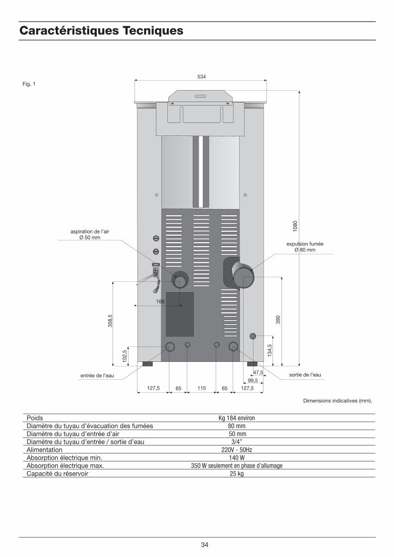
Caractéristiques Tecniques
Kg 184 environ80 mm 50 mm
3/4” 220V - 50Hz
140 W350 W seulement en phase d’allumage
25 kg
Poids Diamètre du tuyau d’évacuation des fuméesDiamètre du tuyau d’entrée d’airDiamètre du tuyau d’entrée / sortie d’eauAlimentation Absorption électrique min.Absorption électrique max.Capacité du réservoir
Fig. 1
34
47,5
99,5127,5 65 115 65 127,5
168
102,
5
358,
5
134,
5
390
1080
534
aspiration de l’airØ 50 mm
expulsion fuméeØ 80 mm
sortie de l’eauentrée de l’eau
Dimensions indicatives (mm).
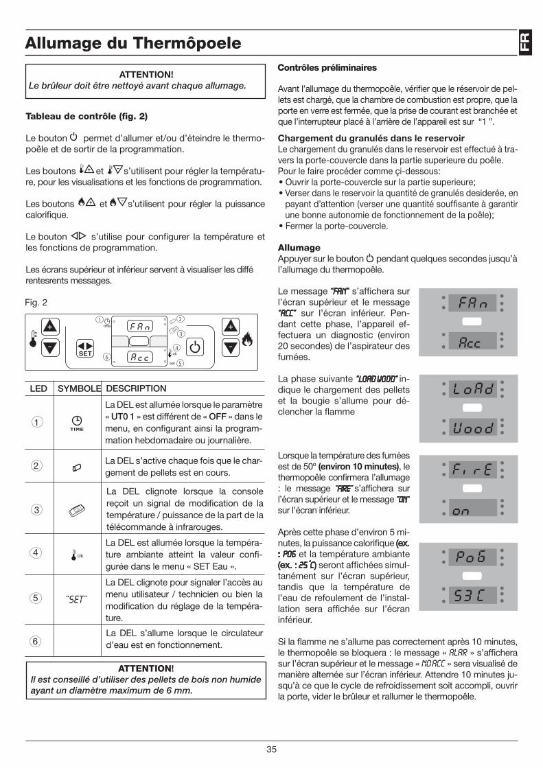
FR
AllumageAppuyer sur le bouton pendant quelques secondes jusqu’à l’allumage du thermopoêle.
Allumage du Thermôpoele
ATTENTION! Le brûleur doit être nettoyé avant chaque allumage.
Tableau de contrôle (fig. 2)
Le bouton permet d’allumer et/ou d’éteindre le thermo-poêle et de sortir de la programmation.
Les boutons et s’utilisent pour régler la températu-re, pour les visualisations et les fonctions de programmation.
Les boutons et s’utilisent pour régler la puissance calorifique.
Le bouton s’utilise pour configurer la température et les fonctions de programmation.
Les écrans supérieur et inférieur servent à visualiser les différentesrents messages.
Avant l’allumage du thermopoêle, vérifier que le réservoir de pel-lets est chargé, que la chambre de combustion est propre, que la porte en verre est fermée, que la prise de courant est branchée et que l’interrupteur placé à l’arrière de l’appareil est sur “1 ”.
La DEL est allumée lorsque le paramètre « UT0 1 » est différent de « OFF » dans le menu, en configurant ainsi la program-mation hebdomadaire ou journalière.
Le message “Fan” s’affichera sur l’écran supérieur et le message “ACC” sur l’écran inférieur. Pen-dant cette phase, l’appareil ef-fectuera un diagnostic (environ 20 secondes) de l’aspirateur des fumées.
La phase suivante “LOAD WOOD” in-dique le chargement des pellets et la bougie s’allume pour dé-clencher la flamme
Lorsque la température des fumées est de 50º (environ 10 minutes), le thermopoêle confirmera l’allumage : le message “FIRE” s’affichera sur l’écran supérieur et le message “ON“ sur l’écran inférieur.
Après cette phase d’environ 5 mi-nutes, la puissance calorifique (ex. : Po6 et la température ambiante (ex. : 25 °C) seront affichées simul-tanément sur l’écran supérieur, tandis que la température de l’eau de refoulement de l’instal-lation sera affichée sur l’écran inférieur.
Si la flamme ne s’allume pas correctement après 10 minutes, le thermopoêle se bloquera : le message « ALAR » s’affichera sur l’écran supérieur et le message « NO ACC » sera visualisé de manière alternée sur l’écran inférieur. Attendre 10 minutes ju-squ’à ce que le cycle de refroidissement soit accompli, ouvrir la porte, vider le brûleur et rallumer le thermopoêle.
Fig. 2
Contrôles préliminaires
35
6
1 2
3
4
5
“SET”
LED SYMBOLE DESCRIPTION
1
2
3
4
5
6
La DEL s’active chaque fois que le char-gement de pellets est en cours.
La DEL clignote lorsque la console reçoit un signal de modification de la température / puissance de la part de la télécommande à infrarouges.
La DEL est allumée lorsque la tempéra-ture ambiante atteint la valeur confi-gurée dans le menu « SET Eau ».
La DEL clignote pour signaler l’accès au menu utilisateur / technicien ou bien la modification du réglage de la tempéra-ture.
La DEL s’allume lorsque le circulateur d’eau est en fonctionnement.
Chargement du granulés dans le reservoirLe chargement du granulés dans le reservoir est effectué à tra-vers la porte-couvercle dans la partie superieure du poêle.Pour le faire procéder comme çi-dessous:• Ouvrir la porte-couvercle sur la partie superieure;• Verser dans le reservoir la quantité de granulés desiderée, en
payant d’attention (verser une quantité souffisante à garantir une bonne autonomie de fonctionnement de la poêle);
• Fermer la porte-couvercle.
ATTENTION!Il est conseillé d’utiliser des pellets de bois non humide ayant un diamètre maximum de 6 mm.
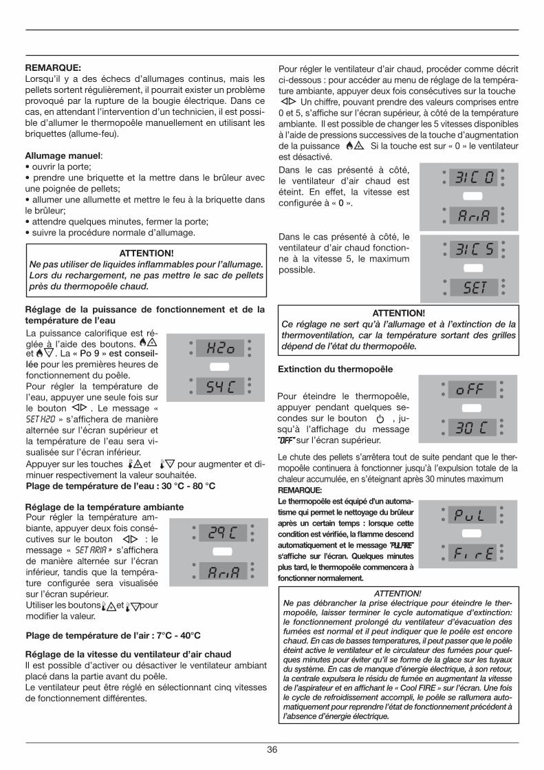
Pour éteindre le thermopoêle, appuyer pendant quelques se-condes sur le bouton , ju-squ’à l’affichage du message “OFF” sur l’écran supérieur.
REMARQUE:Lorsqu’il y a des échecs d’allumages continus, mais les pellets sortent régulièrement, il pourrait exister un problème provoqué par la rupture de la bougie électrique. Dans ce cas, en attendant l’intervention d’un technicien, il est possi-ble d’allumer le thermopoêle manuellement en utilisant les briquettes (allume-feu).
Allumage manuel:• ouvrir la porte;• prendre une briquette et la mettre dans le brûleur avec une poignée de pellets;• allumer une allumette et mettre le feu à la briquette dans le brûleur;• attendre quelques minutes, fermer la porte;• suivre la procédure normale d’allumage.
Réglage de la puissance de fonctionnement et de la température de l’eau
Réglage de la température ambiante
Pour régler la température am-biante, appuyer deux fois consé-cutives sur le bouton : le message « SET ARIA » s’affichera de manière alternée sur l’écran inférieur, tandis que la tempéra-ture configurée sera visualisée sur l’écran supérieur.Utiliser les boutons et pour modifier la valeur.
Appuyer sur les touches et pour augmenter et di-minuer respectivement la valeur souhaitée.Plage de température de l’eau : 30 °C - 80 °C
Extinction du thermopoêle
Le chute des pellets s’arrêtera tout de suite pendant que le ther-mopoêle continuera à fonctionner jusqu’à l’expulsion totale de la chaleur accumulée, en s’éteignant après 30 minutes maximum
ATTENTION!Ce réglage ne sert qu’à l’allumage et à l’extinction de la thermoventilation, car la température sortant des grilles dépend de l’état du thermopoêle.
La puissance calorifique est ré-glée à l’aide des boutons. et . La « Po 9 » est conseil-lée pour les premières heures de fonctionnement du poêle.Pour régler la température de l’eau, appuyer une seule fois sur le bouton
.
. Le message « Set H2o » s’affichera de manière alternée sur l’écran supérieur et la température de l’eau sera vi-sualisée sur l’écran inférieur.
REMARQUE:Le thermopoêle est équipé d’un automa-tisme qui permet le nettoyage du brûleur après un certain temps : lorsque cette condition est vérifiée, la flamme descend automatiquement et le message “PUL FIRE” s‘affiche sur l’écran. Quelques minutes plus tard, le thermopoêle commencera à fonctionner normalement.
36
Plage de température de l’air : 7°C - 40°C
Réglage de la vitesse du ventilateur d’air chaudIl est possible d’activer ou désactiver le ventilateur ambiant placé dans la partie avant du poêle. Le ventilateur peut être réglé en sélectionnant cinq vitesses de fonctionnement différentes.
Pour régler le ventilateur d’air chaud, procéder comme décrit ci-dessous : pour accéder au menu de réglage de la tempéra-ture ambiante, appuyer deux fois consécutives sur la touche Un chiffre, pouvant prendre des valeurs comprises entre 0 et 5, s’affiche sur l’écran supérieur, à côté de la température ambiante. Il est possible de changer les 5 vitesses disponibles à l’aide de pressions successives de la touche d’augmentation de la puissance Si la touche est sur « 0 » le ventilateur est désactivé. Dans le cas présenté à côté, le ventilateur d’air chaud est éteint. En effet, la vitesse est configurée à « 0 ».
Dans le cas présenté à côté, le ventilateur d’air chaud fonction-ne à la vitesse 5, le maximum possible.
ATTENTION!Ne pas débrancher la prise électrique pour éteindre le ther-mopoêle, laisser terminer le cycle automatique d’extinction: le fonctionnement prolongé du ventilateur d’évacuation des fumées est normal et il peut indiquer que le poêle est encore chaud. En cas de basses temperatures, il peut passer que le poêle éteint active le ventilateur et le circulateur des fumées pour quel-ques minutes pour éviter qu’il se forme de la glace sur les tuyaux du système. En cas de manque d’énergie électrique, à son retour, la centrale expulsera le résidu de fumée en augmentant la vitesse de l’aspirateur et en affichant le « Cool FIRE » sur l’écran. Une fois le cycle de refroidissement accompli, le poêle se rallumera auto-matiquement pour reprendre l’état de fonctionnement précédent à l’absence d’énergie électrique.
ATTENTION!Ne pas utiliser de liquides inflammables pour l’allumage. Lors du rechargement, ne pas mettre le sac de pellets près du thermopoêle chaud.

FR
37
Chronothermostat
Paramètre Description Valeursconfigurables
UT01
UT02
UT03
UT04
UT05
UT06
UT07
UT08
UT09
UT10
UT11
UT12
UT13
UT14
UT15
UT16
ÉcranSupérieur SIGNIFICATION
Day 1
Day 2
Day 3
Day 4
Day 5
Day 6
Day 7
OFF
OFF; Day 1, ...,Day7Activation et désactivation du chronoth. Configuration du jour de la semaine
Da 00 a 23Configuration de l’heure courante
Da 00 a 60Configuration des minutes courantes
RéservéConfiguration des pa-ramètres techniques
De 00:00 à 23:50 avec des pas de 10 minutes
Réglage du premier horaire d’allumage du thermopoê-le
De 00:00 à 23:50 avec des pas de 10 minutes
Réglage du premier horai-re d’extinction du thermo-poêle
Entre ON / OFF pour les jours de 1 à 7
Sélection des jours de la semaine pour l’activation du premier horaire
De 00:00 à 23:50 avec des pas de 10 minutes
Réglage du deuxième ho-raire d’allumage du thermo-poêle
De 00:00 à 23:50 avec des pas de 10 minutes
Réglage du deuxième ho-raire d’extinction du ther-mopoêle
Entre ON / OFF pour les jours de 1 à 7
Sélection des jours de la semaine pour l’activation du deuxième horaire
De 00:00 à 23:50 avec des pas de 10 minutes
Réglage du troisième horai-re d’allumage du thermo-poêle
De 00:00 à 23:50 avec des pas de 10 minutes
Réglage du troisième horai-re d’extinction du thermo-poêle
Entre ON / OFF pour les jours de 1 à 7
Sélection des jours de la semaine pour l’activation du troisième horaire
De 00:00 à 23:50 avec des pas de 10 minutes
Réglage du quatrième ho-raire d’allumage du thermo-poêle
De 00:00 à 23:50 avec des pas de 10 minutes
Réglage du quatrième ho-raire d’extinction du ther-mopoêle
Entre ON / OFF pour les jours de 1 à 7
Sélection des jours de la semaine pour l’activation du quatrième horaire
Lundi
Mardi
Mercredi
Jeudi
Vendredi
Samedi
Dimanche
Chronothermostat désactivé
La fonction chronothermostat sert à programmer hebdo-madairement l’allumage et l’extinction automatique du thermopoêle. Pour entrer dans la programmation, appu-yer sur le bouton pendant environ trois secondes, le paramètre “UT01” sera affiché sur l’écran supérieur: en appuyant plusieurs fois sur la touche et en se référant au tableau reporté au-dessous, il est possible de program-mer le poêle selon les propres exigences. Pour sortir de la phase de programmation à tout moment, appuyer sur le bouton . Les paramètres du chronothermostat sont les suivants:
Vous trouverez tout de suite la signification détaillée des pa-ramètres de l’utilisateur :
UT01 Activation et désactivation du chronothermostat et configuration du jour courant.Ce paramètre permet de régler le jour courant de la semai-ne ou de désactiver la programmation. En appuyant sur les bouton la valeur souhaitée est sélectionnée, tel qu’il est montré dans le tableau suivant:
Exemple:si aujourd’hui est jeudi, il faut sélectionner “Day 4”, tandis que si l’on veut allumer le thermopoêle manuellement (sans programmation), il faut sélectionner “OFF”, ainsi le chrono-thermostat est désactivé.
Appuyer sur le bouton pour passer au paramètre sui-vant.
UT02Configuration de l’heure couranteCe paramètre sert à configurer l’heure courante. Appuyer sur les boutons et pour sélectionner l’heure cou-rante.Appuyer sur le bouton pour passer au paramètre sui-vant.
UT03Configuration des minutes courantesAppuyer sur les boutons pour régler les minutes cou-rantes.Appuyer sur le bouton e pour passer au paramètre suivant.
UT04Configuration des paramètres techniquesAppuyer sur le bouton pour passer au paramètre sui-vant.

38
Day 1
Day 2
Day 3
Day 4
Day 5
Day 6
Day 7
off 1 off 2 off 3 off 4 off 5 on 6 on 7
Si le poêle est contrôlé par un thermostat extérieur, le mes-sage “ECO TERM” s’affichera sur l’écran du thermopoêle lor-sque le thermostat atteint la température préétablie.
ATTENTION!le thermostat ambiant ne réalise pas les fonctions d’extinction et d’allumage du thermopoêle, mais le met en modalité d’épargne.
UT08 UT16 Suivre la procédure décrite ci-dessus pour configurer le deuxième, le troisième et le quatrième allumage.
Kit d’eau chaude sanitaire (en option)
Grâce à un kit en option, les thermopoêles ARTEL produi-sent aussi de l’eau chaude sanitaire en continu, de manière saine, sûre et automatique, sans nécessité d’accumula-tion.
Il est conseillé de limiter le débit de l’eau sanitaire à environ 8÷12 litres par minute, pour obtenir un ∆T d’environ 25 ºC.
La pression de l’eau sanitaire ne doit pas dépasser 2 bars.En tout cas il y a un contrôle électronique qui limite la pression du système à max. 2,3 bar.
ÉcranSupérieur SIGNIFICATION
Lundi
Mardi
Mercredi
Jeudi
Vendredi
Samedi
Dimanche
Écran inférieur
ON1/OFF1 - Oui ou Non
ON2/OFF2 - Oui ou Non
ON3/OFF3 - Oui ou Non
ON4/OFF4 - Oui ou Non
ON5/OFF5 - Oui ou Non
ON6/OFF6 - Oui ou Non
ON7/OFF7 - Oui ou Non
Day 1 Lundi
Day 2 Mardi
Day 3 Mercredi
Day 2 Jeudi
Day 2 Vendredi
Day 2 Samedi
Day 2 Dimanche
Confirmer et continuer avec la touche .
UT05Réglage du premier horaire d’allumage du thermopoêleCe paramètre indique l’horaire où l’on souhaite allumer le thermopoêle : à l’aide des boutons et l’heure souhaitée est configurée, avec des pas de 10 minutes. Ap-puyer sur le bouton pour passer au paramètre suivant.
UT06Réglage de l’horaire d’extinction du thermopoêleCe paramètre indique l’horaire où l’on souhaite éteindre le thermopoêle: À l’aide des boutons et l ’ h e u r e souhaitée est configurée, avec des pas de 10 minutes. Appu-yer sur le bouton pour passer au paramètre suivant.
UT07Sélection des jours de la semaineEn appuyant sur le bouton les jours de la semaine sont sélectionnée, tandis qu’en appuyant sur le bouton le jour d’allumage du thermopoêle est activé (ON) ou désac-tivé (OFF), tel qu’il est montré dans le tableau suivant :
Dans l’exemple suivant, le thermopoêle s’allume unique-ment le samedi et le dimanche.
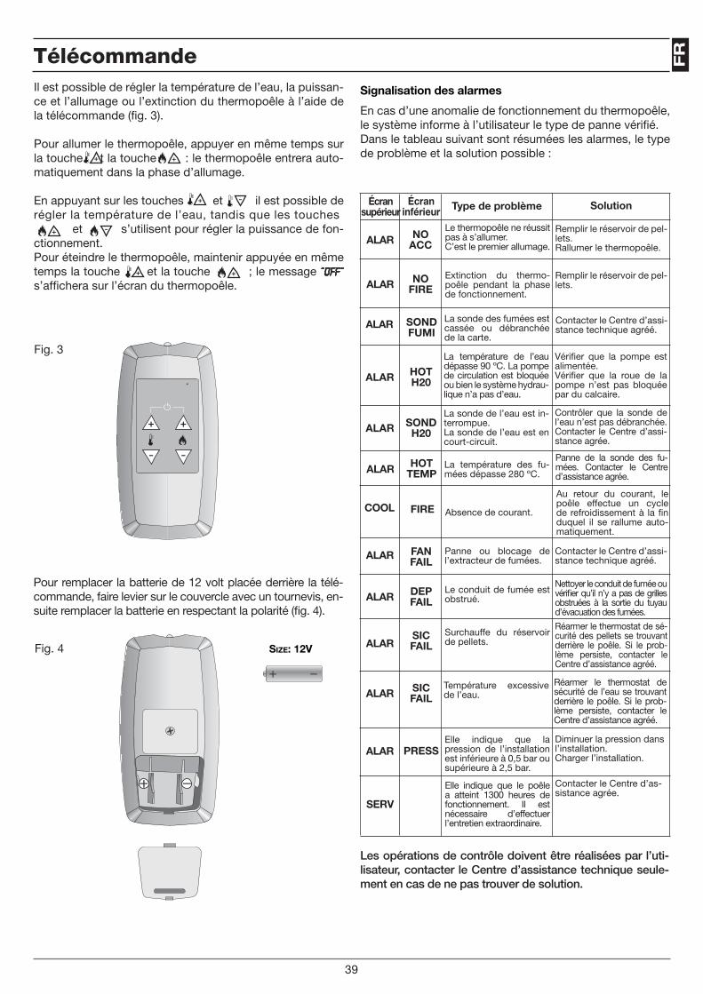
FR
Size: 12V
Pour remplacer la batterie de 12 volt placée derrière la télé-commande, faire levier sur le couvercle avec un tournevis, en-suite remplacer la batterie en respectant la polarité (fig. 4).
Signalisation des alarmes
En cas d’une anomalie de fonctionnement du thermopoêle, le système informe à l’utilisateur le type de panne vérifié.Dans le tableau suivant sont résumées les alarmes, le type de problème et la solution possible :
Écran supérieur
Écran inférieur Type de problème Solution
ALAR FAN FAIL
ALAR DEP FAIL
ALARSIC FAIL
ALAR SIC FAIL
ALAR PRESS
Panne ou blocage de l’extracteur de fumées.
Le conduit de fumée est obstrué.
Surchauffe du réservoir de pellets.
Température excessive de l’eau.
Elle indique que la pression de l’installation est inférieure à 0,5 bar ou supérieure à 2,5 bar.
Contacter le Centre d’assi-stance technique agréé.
Nettoyer le conduit de fumée ou vérifier qu’il n’y a pas de grilles obstruées à la sortie du tuyau d’évacuation des fumées.
Réarmer le thermostat de sé-curité des pellets se trouvant derrière le poêle. Si le prob-lème persiste, contacter le Centre d’assistance agréé.
Réarmer le thermostat de sécurité de l’eau se trouvant derrière le poêle. Si le prob-lème persiste, contacter le Centre d’assistance agréé.
Diminuer la pression dans l’installation. Charger l’installation.
ALAR NO ACC
Le thermopoêle ne réussit pas à s’allumer.C’est le premier allumage.
Remplir le réservoir de pel-lets.Rallumer le thermopoêle.
ALAR NO FIRE
Extinction du thermo-poêle pendant la phase de fonctionnement.
Remplir le réservoir de pel-lets.
ALAR SOND FUMI
La sonde des fumées est cassée ou débranchée de la carte.
Contacter le Centre d’assi-stance technique agréé.
ALAR HOT H20
La température de l’eau dépasse 90 ºC. La pompe de circulation est bloquée ou bien le système hydrau-lique n’a pas d’eau.
Vérifier que la pompe est alimentée.Vérifier que la roue de la pompe n’est pas bloquée par du calcaire.
ALAR SOND H20
La sonde de l’eau est in-terrompue.La sonde de l’eau est en court-circuit.
Contrôler que la sonde de l’eau n’est pas débranchée.Contacter le Centre d’assi-stance agrée.
ALAR HOT TEMP
La température des fu-mées dépasse 280 ºC.
Panne de la sonde des fu-mées. Contacter le Centre d’assistance agrée.
COOL FIRE Absence de courant.
Au retour du courant, le poêle effectue un cycle de refroidissement à la fin duquel il se rallume auto-matiquement.
Les opérations de contrôle doivent être réalisées par l’uti-lisateur, contacter le Centre d’assistance technique seule-ment en cas de ne pas trouver de solution.
Fig. 3
Fig. 4
Télécommande
Size: 12V
39
SERV
Elle indique que le poêle a atteint 1300 heures de fonctionnement. Il est nécessaire d’effectuer l’entretien extraordinaire.
Contacter le Centre d’as-sistance agrée.
Il est possible de régler la température de l’eau, la puissan-ce et l’allumage ou l’extinction du thermopoêle à l’aide de la télécommande (fig. 3).
Pour allumer le thermopoêle, appuyer en même temps sur la touche et la touche : le thermopoêle entrera auto-matiquement dans la phase d’allumage.
En appuyant sur les touches et il est possible de régler la température de l’eau, tandis que les touches et s’utilisent pour régler la puissance de fon-ctionnement.Pour éteindre le thermopoêle, maintenir appuyée en même temps la touche et la touche ; le message ”OFF” s’affichera sur l’écran du thermopoêle.
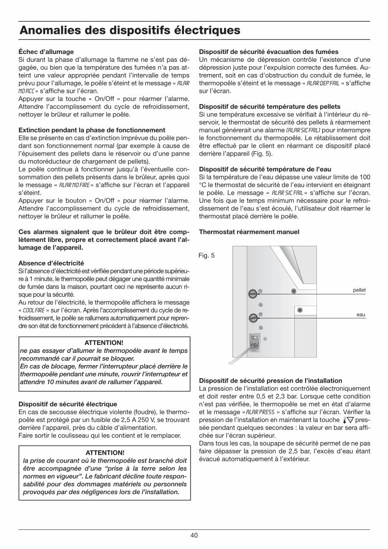
Échec d’allumageSi durant la phase d’allumage la flamme ne s’est pas dé-gagée, ou bien que la température des fumées n’a pas at-teint une valeur appropriée pendant l’intervalle de temps prévu pour l’allumage, le poêle s’éteint et le message « Alar No Acc » s’affiche sur l’écran.Appuyer sur la touche « On/Off » pour réarmer l’alarme. Attendre l’accomplissement du cycle de refroidissement, nettoyer le brûleur et rallumer le poêle.
Extinction pendant la phase de fonctionnementElle se présente en cas d’extinction imprévue du poêle pen-dant son fonctionnement normal (par exemple à cause de l’épuisement des pellets dans le réservoir ou d’une panne du motoréducteur de chargement de pellets).Le poêle continue à fonctionner jusqu’à l’éventuelle con-sommation des pellets présents dans le brûleur, après quoi le message « Alar No Fire » s’affiche sur l’écran et l’appareil s’éteint.Appuyer sur le bouton « On/Off » pour réarmer l’alarme. Attendre l’accomplissement du cycle de refroidissement, nettoyer le brûleur et rallumer le poêle.
Ces alarmes signalent que le brûleur doit être comp-lètement libre, propre et correctement placé avant l’al-lumage de l’appareil.
Absence d’électricitéSi l’absence d’électricité est vérifiée pendant une période supérieu-re à 1 minute, le thermopoêle peut dégager une quantité minimale de fumée dans la maison, pourtant ceci ne représente aucun ri-sque pour la sécurité.Au retour de l’électricité, le thermopoêle affichera le message « Cool Fire » sur l’écran. Après l’accomplissement du cycle de re-froidissement, le poêle se rallumera automatiquement pour repren-dre son état de fonctionnement précédent à l’absence d’électricité.
Dispositif de sécurité électrique En cas de secousse électrique violente (foudre), le thermo-poêle est protégé par un fusible de 2,5 A 250 V, se trouvant derrière l’appareil, près du câble d’alimentation.Faire sortir le coulisseau qui les contient et le remplacer.
pellet
eau
Fig. 5
Anomalies des dispositifs électriques
40
Dispositif de sécurité évacuation des fuméesUn mécanisme de dépression contrôle l’existence d’une dépression juste pour l’expulsion correcte des fumées. Au-trement, soit en cas d’obstruction du conduit de fumée, le thermopoêle s’éteint et le message « Alar Dep Fail » s’affiche sur l’écran.
Dispositif de sécurité température des pelletsSi une température excessive se vérifiait à l’intérieur du ré-servoir, le thermostat de sécurité des pellets à réarmement manuel générerait une alarme (Alar Sic Fail) pour interrompre le fonctionnement du thermopoêle. Le rétablissement doit être effectué par le client en réarmant ce dispositif placé derrière l’appareil (Fig. 5).
Dispositif de sécurité température de l’eauSi la température de l’eau dépasse une valeur limite de 100 °C le thermostat de sécurité de l’eau intervient en éteignant le poêle. Le message « Alar Sic Fail » s’affiche sur l’écran. Une fois que le temps minimum nécessaire pour le refroi-dissement de l’eau s’est écoulé, l’utilisateur doit réarmer le thermostat placé derrière le poêle.
Thermostat réarmement manuel
Dispositif de sécurité pression de l’installationLa pression de l’installation est contrôlée électroniquement et doit rester entre 0,5 et 2,3 bar. Lorsque cette condition n’est pas vérifiée, le thermopoêle se met en état d’alarme et le message « Alar Press » s’affiche sur l’écran. Vérifier la pression de l’installation en maintenant la touche pres-sée pendant quelques secondes : la valeur en bar sera affi-chée sur l’écran supérieur.Dans tous les cas, la soupape de sécurité permet de ne pas faire dépasser la pression de 2,5 bar, l’excès d’eau étant évacué automatiquement à l’extérieur.
ATTENTION!ne pas essayer d’allumer le thermopoêle avant le temps recommandé car il pourrait se bloquer.En cas de blocage, fermer l’interrupteur placé derrière le thermopoêle pendant une minute, rouvrir l’interrupteur et attendre 10 minutes avant de rallumer l’appareil.
ATTENTION!la prise de courant où le thermopoêle est branché doit être accompagnée d’une “prise à la terre selon les normes en vigueur”. Le fabricant décline toute respon-sabilité pour des dommages matériels ou personnels provoqués par des négligences lors de l’installation.
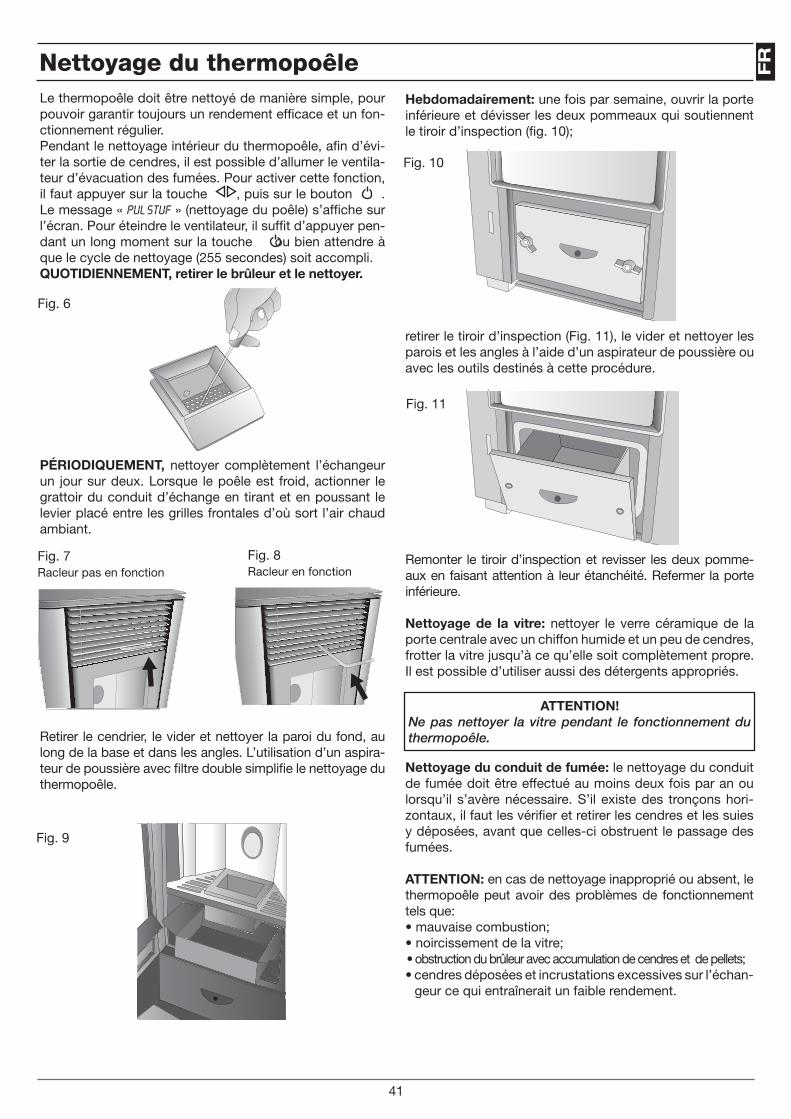
FR
Hebdomadairement: une fois par semaine, ouvrir la porte inférieure et dévisser les deux pommeaux qui soutiennent le tiroir d’inspection (fig. 10);
retirer le tiroir d’inspection (Fig. 11), le vider et nettoyer les parois et les angles à l’aide d’un aspirateur de poussière ou avec les outils destinés à cette procédure.
Remonter le tiroir d’inspection et revisser les deux pomme-aux en faisant attention à leur étanchéité. Refermer la porte inférieure.
Nettoyage de la vitre: nettoyer le verre céramique de la porte centrale avec un chiffon humide et un peu de cendres, frotter la vitre jusqu’à ce qu’elle soit complètement propre. Il est possible d’utiliser aussi des détergents appropriés.
Nettoyage du conduit de fumée: le nettoyage du conduit de fumée doit être effectué au moins deux fois par an ou lorsqu’il s’avère nécessaire. S’il existe des tronçons hori-zontaux, il faut les vérifier et retirer les cendres et les suies y déposées, avant que celles-ci obstruent le passage des fumées.
ATTENTION: en cas de nettoyage inapproprié ou absent, le thermopoêle peut avoir des problèmes de fonctionnement tels que:• mauvaise combustion;• noircissement de la vitre;• obstruction du brûleur avec accumulation de cendres et de pellets;• cendres déposées et incrustations excessives sur l’échan-
geur ce qui entraînerait un faible rendement.
ATTENTION!Ne pas nettoyer la vitre pendant le fonctionnement du thermopoêle.
Fig. 10
Fig. 11
Nettoyage du thermopoêle
41
Le thermopoêle doit être nettoyé de manière simple, pour pouvoir garantir toujours un rendement efficace et un fon-ctionnement régulier. Pendant le nettoyage intérieur du thermopoêle, afin d’évi-ter la sortie de cendres, il est possible d’allumer le ventila-teur d’évacuation des fumées. Pour activer cette fonction, il faut appuyer sur la touche , puis sur le bouton . Le message « PUL STUF » (nettoyage du poêle) s’affiche sur l’écran. Pour éteindre le ventilateur, il suffit d’appuyer pen-dant un long moment sur la touche ou bien attendre à que le cycle de nettoyage (255 secondes) soit accompli.QUOTIDIENNEMENT, retirer le brûleur et le nettoyer.
PÉRIODIQUEMENT, nettoyer complètement l’échangeur un jour sur deux. Lorsque le poêle est froid, actionner le grattoir du conduit d’échange en tirant et en poussant le levier placé entre les grilles frontales d’où sort l’air chaud ambiant.
Retirer le cendrier, le vider et nettoyer la paroi du fond, au long de la base et dans les angles. L’utilisation d’un aspira-teur de poussière avec filtre double simplifie le nettoyage du thermopoêle.
Fig. 6
Fig. 7Racleur pas en fonction
Fig. 8Racleur en fonction
Fig. 9

ATTENTION!Ces opérations doivent être effectuées par un techni-cien qualifié ou par l’utilisateur, qui sera le responsable en cas de dommages lors de l’entretien.effecteur cet entretien avec le thermopoêle froid et sans électricité. cet entretien est à la charge du client s’il est réalisé par un centre d’assistance agrée.
NOTE
Entratien extraordinaire
42
Cod
. 001
041
ES
Apreciado cliente,Al mismo tiempo que le felicitamos por haber adquirido una termo estufa, le recordamos que las termo estufas a pellets, constituyen la más innovadora solución en calefacción, fruto de la tecnología más avanzada con una calidad de fabricación de altísimo nivel y un diseño sencillo y elegante que se adaptan bien a cada ambiente, haciéndolos más acogedores gracias al calor envolvente que sólo la llama le puede proporcionar.Este manual le ayudará a utilizar correctamente su termo estufa. Le aconsejamos por lo tanto leerlo atentamente antes del uso.Las termo estufas funcionan exclusivamente con pellets de madera de máx. 6 mm. de diámetro, están provistas de un inter-cambiador que permite desarrollar un rendimiento de aproximadamente el 90%.Las termo estufas están provistas de crono termóstato que garantiza hasta 4 encendidos y 4 apagados semanales, permitien-do de este modo su gestión autónoma.Las termo estufas llevan el calor a los radiadores de su instalación, con una potencia térmica que se regula en función del ambiente que hay que calentar: basta con programar de forma manual la temperatura del agua de la instalación se aconseja entre 60º - 75º.Las termo estufas están provistas también de ventiladores tangenciales para la difusión del aire caliente, que permite el ca-lentamiento a convección forzada del local donde se encuentra instalada.Gracias a un kit opcional, producen también agua caliente sanitaria de modo continuo, sano y seguro, funcionando automáti-camente, sin necesidad de acumulación.Las termo estufas han sido equipadas de sofisticados automatismos y sistema de control y seguridad, que garantizan un eficaz y práctico funcionamiento.La instalación y el mantenimiento deben de ser efectuados por personal cualificado, conforme a las leyes vigentes en materia y según las indicaciones del fabricante.El presente manual de uso y mantenimiento, constituye parte integrante del producto.Antes de proceder a la instalación, uso, o al mantenimiento del producto, es necesario leer atentamente las indicaciones que contiene este manual.Esta termo estufa deberá ser destinada únicamente al uso para el cual está expresamente fabricada. Por lo tanto toda responsabilidad por eventuales daños a personas animales o cosas por un uso inapropiado del producto será responsabilidad del usuario.
43
ATENCIÓNDurante los primeros dos tres encendidos de la termo estufa, los vapores emitidos por la pintura pueden provocar mal olor, por lo tanto es aconsejable airear bien el local evitando permanecer de modo prolongado delante de la termo estufa.
La instalación debe ser efectuada por personal cualificado, el cual a sumirá la íntegra responsabilidad de la instalación definitiva y del consiguiente buen funcionamiento del producto instalado. No será responsabilidad del fabricante, cuando la instalación sea realizada por personal no cualificado, o en el caso de no considerar las advertencias generales y de las instrucciones de la instalación.
Tras haber quitado el embalaje, verificar que el contenido esté íntegro y completo: en caso de que no ser así, dirigirse al proveedor al cuál se le ha adquirido la termo estufa.Antes de la instalación es aconsejable realizar un lavado minucioso de los tubos de la instalación, con el fin de remover posibles residuos que podrían comprometer el buen funcionamiento del aparato.En caso de no utilizar la termo estufa durante un largo período se aconseja efectuar las siguientes operaciones:• Desconectar de la toma de alimentación eléctrica• Cerrar los grifos del agua, tanto de la instalación térmica como de la sanitaria.El mantenimiento extraordinario de la termo estufa debe realizarse al menos una vez al año. Dicho mantenimiento debe programarse con tiempo por el Servicio Técnico de Asistencia y será a cargo del cliente.
POR RAZONES DE SEGURIDAD CONVIENE RECORDAR QUE:
• Se desaconseja el uso de la termo estufa por niños y personas discapacitadas no asistidas.• No tocar la termo estufa si se está descalzo o con alguna parte del cuerpo mojada o húmeda.• Está prohibido modificar los dispositivos de seguridad o de regulación sin la previa autorización o indicaciones del fa-bricante.• No estirar, arrancar, torcer los cables eléctricos que sobresalen de la caldera a pesar de que ésta esté desconectada de la red de alimentación eléctrica.• Evitar tapar o reducir la circulación del aire comburente, indispensable para una correcta combustión.• No dejar los elementos del embalaje al alcance de los niños o de personas no discapacitadas sin asistencia.
En caso de incendio, retirar la alimentación eléctrica, usar un extintor según norma y avisar a los bomberos. Contactar con el centro de asistencia técnica autorizado.

Características Técnicas
alrededor de 184 kg.80 mm 50 mm
3/4” 220V - 50Hz
140 W 350 W solo fase encendido.
25 kilos.
PesoDiámetro tubo descarga humos Diámetro tubo entrada aire Diámetro entrada/salida de agua Alimentación eléctricaAbsorción eléctrica mínimaAbsorción eléctrica máximaCapacidad del depósito de pellets
Fig. 1
44
47,5
99,5127,5 65 115 65 127,5
168
102,
5
358,
5
134,
5
390
1080
534
Aspiración aire comburenteØ 50 mm.
Expulsión humos Ø. 80mm
Salida del aguaEntrada del agua
Dimensiones aproximadas en milímetros

ES
EncendidoPresionar el pulsador durante algunos segundos hasta la puesta en marcha de la termo estufa.
Encendido Termo estufa
ATENCIÓNEl cenicero debe estar limpio antes de cada encendido
Cuadro de mandos (Fig. 2)
El pulsador se utiliza para el encendido y/o el apagado de la termo estufa y para salir de la programación.
Los pulsadores y se utilizan para regular la tempe-ratura para visualizaciones y funciones de programación.
Los pulsadores y se utilizan para regular la po-tencia calórica.
El pulsador se utiliza para programar la temperatura y las funciones de programación.
Los displays superior e inferior sirven para visualizar varios mensajes.
Antes del encendido de la termo estufa verificar que el depósito de pel-let esté cargado que la cámara de combustión esté limpia que la puerta de vidrio esté cerrada, que la toma de corriente esté conectado y que el interruptor situado en la parte posterior esté en la posición.”1”
El les está encendido cuando el conte-nido del menú UT01 no esté en OFF.
ATENCIÓNSe recomienda utilizar pellets de madera de 6mm. máx. de diámetro, y que este no sea húmedo.
En el display superior aparecerá “FAN” y sobre el display inferior “ACC”. Durante está fase el apara-to ejecutará un diagnóstico du-rante 20 seg. sobre el ventilador de los humos.
La siguiente fase “LOAD WOOD”, está indica la carga de pellets y la resistencia se encenderá para avivar la llama.
Cuando la temperatura de los humos llegue alrededor de 50ºC, durante 10 minutos la termo estufa convalidará el encendido y sobre el display superior apa-recerá “FIRE” mientras sobre el display inferior aparecerá “ON”.
Tras esta fase de duración alrede-dor de 5 minutos sobre el display superior se visualizará al mismo tiempo la potencia calórica (por ejemplo P06), y la temperatura ambiente (por ejemplo 25), mien-tras que sobre el display inferior se visualizará la temperatura del agua de ida a la instalación.
Si no se enciende la llama correctamente en 10 minutos, la termo estufa se bloquea.Sobre el display superior se visualizará “ALAR” y sobre el display inferior de modo alternado “NO ACC”, esperar 10 mi-nutos a que se complete el ciclo de enfriamiento, abrir la puerta vaciar el cenicero y proceder a un nuevo encendido.
Fig. 2
Señalización del cuadro de mandos:
45
6
1 2
3
4
5
“SET”
LED SìMBOLO DESCRIPCIÓN
1
2
3
4
5
6
El led se habilita cada vez que se realiza la carga del pellet.
El led parpadea cuando el equipo re-cibe la señal de modificación tempe-ratura/potencia por parte del mando a distancia.
El led está encendido cuando la tempe-ratura ambiente llega al valor de tempera-tura impuesto en el menú SET Acqua.
El led parpadea para indicar que se está accediendo al menú usuario/téc-nico o que se está modificando la tem-peratura.
El led se enciende cuando está en fun-cionamiento la bomba circuladora.
Dimensiones aproximadas en milímetros
Carga del deposito pellet en el depósito La carga del pellet en el depósito se realiza a través de la tapa situada en la parte superior de la estufa.Para efectuar la carga proceder del modo siguiente:• Abrir la tapa situada en la parte superior de la termo estufa.• Verter en el interior del depósito la cantidad de pellet deseado, prestando atención en verter la cantidad suficiente para garanti-zar una cierta autonomía del funcionamiento de la termo estufa.• Cerrar la tapa de carga del pellet.
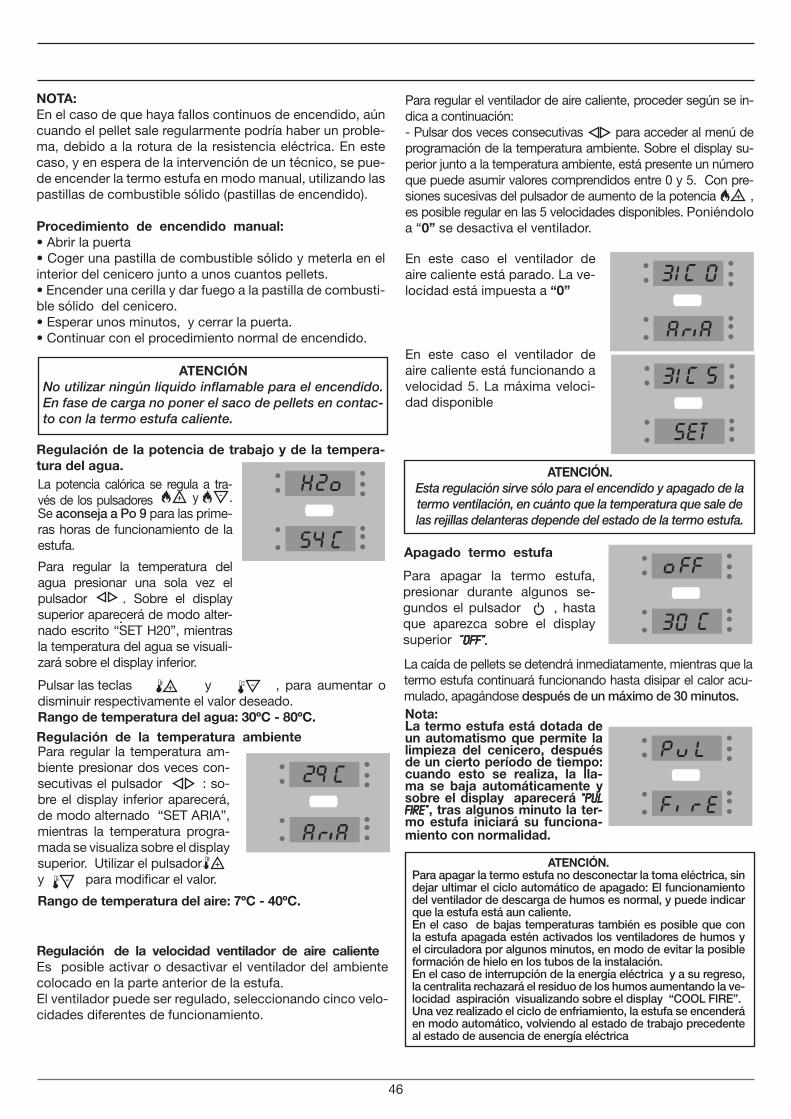
Para apagar la termo estufa, presionar durante algunos se-gundos el pulsador , hasta que aparezca sobre el display superior “OFF”.
NOTA:En el caso de que haya fallos continuos de encendido, aún cuando el pellet sale regularmente podría haber un proble-ma, debido a la rotura de la resistencia eléctrica. En este caso, y en espera de la intervención de un técnico, se pue-de encender la termo estufa en modo manual, utilizando las pastillas de combustible sólido (pastillas de encendido).
Procedimiento de encendido manual:• Abrir la puerta• Coger una pastilla de combustible sólido y meterla en el interior del cenicero junto a unos cuantos pellets.• Encender una cerilla y dar fuego a la pastilla de combusti-ble sólido del cenicero.• Esperar unos minutos, y cerrar la puerta.• Continuar con el procedimiento normal de encendido.
Regulación de la potencia de trabajo y de la tempera-tura del agua.
Regulación de la temperatura ambiente
Para regular la temperatura am-biente presionar dos veces con-secutivas el pulsador : so-bre el display inferior aparecerá, de modo alternado “SET ARIA”, mientras la temperatura progra-mada se visualiza sobre el display superior. Utilizar el pulsador y para modificar el valor.
Pulsar las teclas y , para aumentar o disminuir respectivamente el valor deseado. Rango de temperatura del agua: 30ºC - 80ºC.
ATENCIÓNNo utilizar ningún líquido inflamable para el encendido. En fase de carga no poner el saco de pellets en contac-to con la termo estufa caliente.
Apagado termo estufa
La caída de pellets se detendrá inmediatamente, mientras que la termo estufa continuará funcionando hasta disipar el calor acu-mulado, apagándose después de un máximo de 30 minutos.
ATENCIÓN.Esta regulación sirve sólo para el encendido y apagado de la termo ventilación, en cuánto que la temperatura que sale de las rejillas delanteras depende del estado de la termo estufa.
La potencia calórica se regula a tra-vés de los pulsadores y . Se aconseja a Po 9 para las prime-ras horas de funcionamiento de la estufa.
Para regular la temperatura del agua presionar una sola vez el pulsador
.
. Sobre el display superior aparecerá de modo alter-nado escrito “SET H20”, mientras la temperatura del agua se visuali-zará sobre el display inferior.
Nota:La termo estufa está dotada de un automatismo que permite la limpieza del cenicero, después de un cierto período de tiempo: cuando esto se realiza, la lla-ma se baja automáticamente y sobre el display aparecerá “PUL FIRE”, tras algunos minuto la ter-mo estufa iniciará su funciona-miento con normalidad.
46
Rango de temperatura del aire: 7ºC - 40ºC.
Regulación de la velocidad ventilador de aire calienteEs posible activar o desactivar el ventilador del ambiente colocado en la parte anterior de la estufa.El ventilador puede ser regulado, seleccionando cinco velo-cidades diferentes de funcionamiento.
Para regular el ventilador de aire caliente, proceder según se in-dica a continuación: - Pulsar dos veces consecutivas para acceder al menú de programación de la temperatura ambiente. Sobre el display su-perior junto a la temperatura ambiente, está presente un número que puede asumir valores comprendidos entre 0 y 5. Con pre-siones sucesivas del pulsador de aumento de la potencia , es posible regular en las 5 velocidades disponibles. Poniéndolo a “0” se desactiva el ventilador.
En este caso el ventilador de aire caliente está parado. La ve-locidad está impuesta a “0”
En este caso el ventilador de aire caliente está funcionando a velocidad 5. La máxima veloci-dad disponible
ATENCIÓN.Para apagar la termo estufa no desconectar la toma eléctrica, sin dejar ultimar el ciclo automático de apagado: El funcionamiento del ventilador de descarga de humos es normal, y puede indicar que la estufa está aun caliente.En el caso de bajas temperaturas también es posible que con la estufa apagada estén activados los ventiladores de humos y el circuladora por algunos minutos, en modo de evitar la posible formación de hielo en los tubos de la instalación.En el caso de interrupción de la energía eléctrica y a su regreso, la centralita rechazará el residuo de los humos aumentando la ve-locidad aspiración visualizando sobre el display “COOL FIRE”.Una vez realizado el ciclo de enfriamiento, la estufa se encenderá en modo automático, volviendo al estado de trabajo precedente al estado de ausencia de energía eléctrica
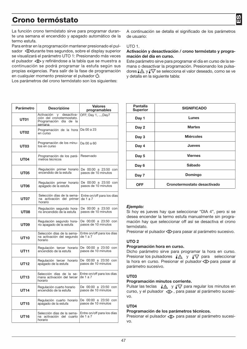
ESCrono termóstato
La función crono termóstato sirve para programar duran-te una semana el encendido y apagado automático de la termo estufa. Para entrar en la programación mantener presionado el pul-sador durante tres segundos, sobre el display superior se visualizará el parámetro UTO 1: Presionando más veces el pulsador y refiriéndose a la tabla que se muestra a continuación se podrá programar la estufa según sus propias exigencias. Para salir de la fase de programación en cualquier momento presionar el pulsador .Los parámetros del crono termóstato son los siguientes:
A continuación se detalla el significado de los parámetros de usuario:
UTO 1.Activación y desactivación / crono termóstato y progra-mación del día en curso.Este parámetro sirve para programar el día en curso de la se-mana o desactivar la programación. Presionando los pulsa-dores y se selecciona el valor deseado, como se ve y detalla en la siguiente tabla:
Ejemplo:Si hoy es jueves hay que seleccionar “DIA 4”, pero si se desea encender la termo estufa manualmente sin progra-mación hay que seleccionar off así se desactiva el crono termóstato. Presionar el pulsador para pasar al parámetro sucesivo.
UTO 2 Programación hora en curso. Dicho parámetro sirve para programar la hora en curso. Presionar los pulsadores y para seleccionar la hora en curso. Presionar el pulsador para pasar al parámetro sucesivo.
UT03Programación minutos corriente. Pulsar las teclas y para regular los minutos en curso, y el pulsador , para pasar al parámetro sucesi-vo.
UT04Programación de los parámetros técnicos. Presionar el pulsador para pasar al parámetro sucesi-vo.
47
Parámetro Descrizióne Valoresprogramables
UT01
UT02
UT03
UT04
UT05
UT06
UT07
UT08
UT09
UT10
UT11
UT12
UT13
UT14
UT15
UT16
PantallaSuperior SIGNIFICADO
Day 1
Day 2
Day 3
Day 4
Day 5
Day 6
Day 7
OFF
OFF; Day 1, ...,Day7Activación y desactiva-ción del cronotermostato. Programación día de la semana
Da 00 a 23Programación de la hora en curso
Da 00 a 60Programación de los minu-tos en curso
ReservadoProgramación de los pará-metros técnicos
De 00:00 a 23:50 con pasos de 10 minutos
Regulación primer horario encendido de la estufa
De 00:00 a 23:50 con pasos de 10 minutos
Regulación primer horario apagado de la estufa
Entre on/off para los días de 1 a 7
Selección días de la sema-na activación del primer horario
De 00:00 a 23:50 con pasos de 10 minutos
Regulación segundo hora-rio encendido de la estufa
De 00:00 a 23:50 con pasos de 10 minutos
Regulación segundo hora-rio apagado de la estufa
Entre on/off para los días de 1 a 7
Selección días de la sema-na activación del segundo horario
De 00:00 a 23:50 con pasos de 10 minutos
Regulación tercer horario encendido de la estufa
De 00:00 a 23:50 con pasos de 10 minutos
Regulación tercer horario apagado de la estufa
Entre on/off para los días de 1 a 7
Selección días de la se-mana activación del tercer horario
De 00:00 a 23:50 con pasos de 10 minutos
Regulación cuarto horario encendido de la estufa
De 00:00 a 23:50 con pasos de 10 minutos
Regulación cuarto horario apagado de la estufa
Entre on/off para los días de 1 a 7
Selección días de la sema-na activación del cuarto horario
Lunes
Martes
Miércoles
Jueves
Viernes
Sábado
Domingo
Cronotermostato desactivado
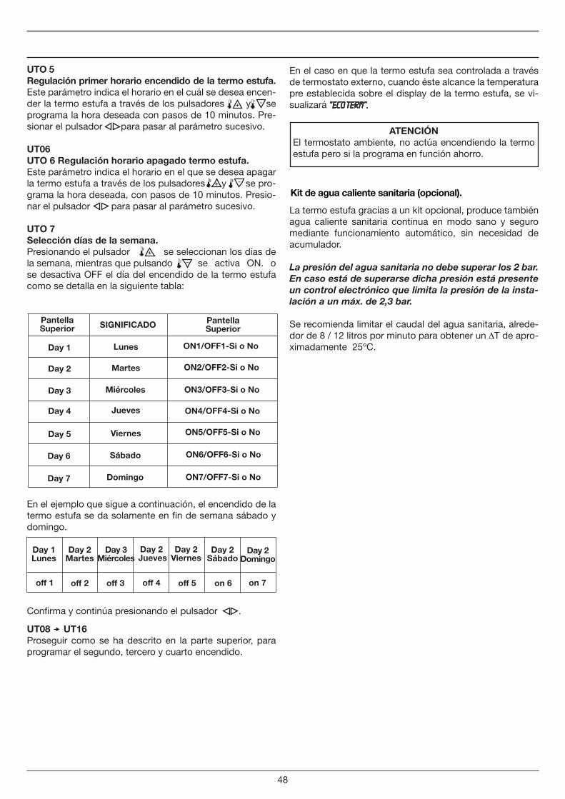
UTO 5 Regulación primer horario encendido de la termo estufa. Este parámetro indica el horario en el cuál se desea encen-der la termo estufa a través de los pulsadores y se programa la hora deseada con pasos de 10 minutos. Pre-sionar el pulsador para pasar al parámetro sucesivo.
UT06UTO 6 Regulación horario apagado termo estufa. Este parámetro indica el horario en el que se desea apagar la termo estufa a través de los pulsadores y se pro-grama la hora deseada, con pasos de 10 minutos. Presio-nar el pulsador para pasar al parámetro sucesivo.
UTO 7 Selección días de la semana. Presionando el pulsador se seleccionan los días de la semana, mientras que pulsando se activa ON. o se desactiva OFF el día del encendido de la termo estufa como se detalla en la siguiente tabla:
En el ejemplo que sigue a continuación, el encendido de la termo estufa se da solamente en fin de semana sábado y domingo.
Confirma y continúa presionando el pulsador .
En el caso en que la termo estufa sea controlada a través de termostato externo, cuando éste alcance la temperatura pre establecida sobre el display de la termo estufa, se vi-sualizará “ECO TERM”.
ATENCIÓNEl termostato ambiente, no actúa encendiendo la termo estufa pero si la programa en función ahorro.
UT08 UT16 Proseguir como se ha descrito en la parte superior, para programar el segundo, tercero y cuarto encendido.
Kit de agua caliente sanitaria (opcional).
La termo estufa gracias a un kit opcional, produce también agua caliente sanitaria continua en modo sano y seguro mediante funcionamiento automático, sin necesidad de acumulador.
La presión del agua sanitaria no debe superar los 2 bar. En caso está de superarse dicha presión está presente un control electrónico que limita la presión de la insta-lación a un máx. de 2,3 bar.
Se recomienda limitar el caudal del agua sanitaria, alrede-dor de 8 / 12 litros por minuto para obtener un T de apro-ximadamente 25ºC.
48
Pantella Superior SIGNIFICADO
Day 1
Day 2
Day 3
Day 4
Day 5
Day 6
Day 7
Pantella Superior
off 1 off 2 off 3 off 4 off 5 on 6 on 7
Lunes
Martes
Miércoles
Jueves
Viernes
Sábado
Domingo
ON1/OFF1-Si o No
ON2/OFF2-Si o No
ON3/OFF3-Si o No
ON4/OFF4-Si o No
ON5/OFF5-Si o No
ON6/OFF6-Si o No
ON7/OFF7-Si o No
Day 1 Lunes
Day 2 Martes
Day 3 Miércoles
Day 2 Jueves
Day 2 Viernes
Day 2 Sábado
Day 2 Domingo
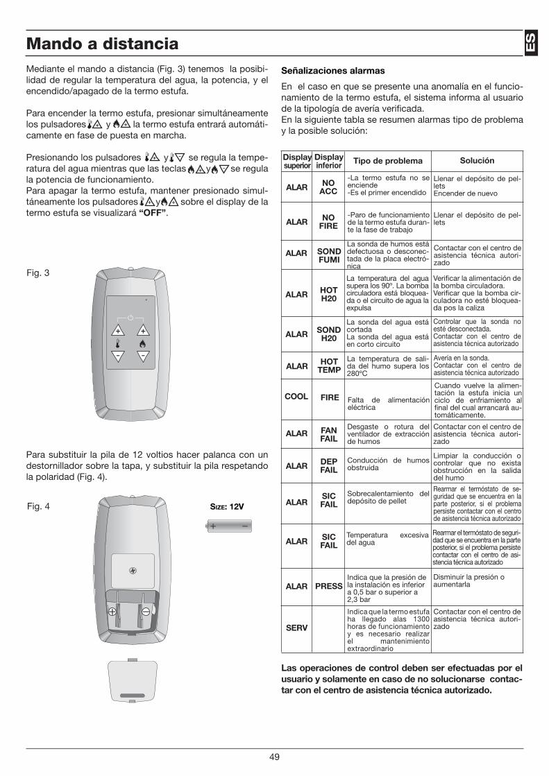
ES
Size: 12V
Mediante el mando a distancia (Fig. 3) tenemos la posibi-lidad de regular la temperatura del agua, la potencia, y el encendido/apagado de la termo estufa.
Para encender la termo estufa, presionar simultáneamente los pulsadores y la termo estufa entrará automáti-camente en fase de puesta en marcha.
Presionando los pulsadores y se regula la tempe-ratura del agua mientras que las teclas y se regula la potencia de funcionamiento.Para apagar la termo estufa, mantener presionado simul-táneamente los pulsadores y sobre el display de la termo estufa se visualizará “OFF”.
Para substituir la pila de 12 voltios hacer palanca con un destornillador sobre la tapa, y substituir la pila respetando la polaridad (Fig. 4).
Señalizaciones alarmas
En el caso en que se presente una anomalía en el funcio-namiento de la termo estufa, el sistema informa al usuario de la tipología de avería verificada.En la siguiente tabla se resumen alarmas tipo de problema y la posible solución:
Displaysuperior
Displayinferior Tipo de problema Solución
ALAR FAN FAIL
ALAR DEP FAIL
ALARSIC FAIL
ALAR SIC FAIL
ALAR PRESS
Desgaste o rotura del ventilador de extracción de humos
Conducción de humos obstruida
Sobrecalentamiento del depósito de pellet
Temperatura excesiva del agua
Indica que la presión de la instalación es inferior a 0,5 bar o superior a 2,3 bar
Contactar con el centro de asistencia técnica autori-zado
Limpiar la conducción o controlar que no exista obstrucción en la salida del humo
Rearmar el termóstato de se-guridad que se encuentra en la parte posterior, si el problema persiste contactar con el centro de asistencia técnica autorizado
Rearmar el termóstato de seguri-dad que se encuentra en la parte posterior, si el problema persiste contactar con el centro de asi-stencia técnica autorizado
Disminuir la presión o aumentarla
ALAR NO ACC
-La termo estufa no se enciende-Es el primer encendido
Llenar el depósito de pel-letsEncender de nuevo
ALAR NO FIRE
-Paro de funcionamiento de la termo estufa duran-te la fase de trabajo
Llenar el depósito de pel-lets
ALAR SOND FUMI
La sonda de humos está defectuosa o desconec-tada de la placa electró-nica
Contactar con el centro de asistencia técnica autori-zado
ALAR HOT H20
La temperatura del agua supera los 90º. La bomba circuladora está bloquea-da o el circuito de agua la expulsa
Verificar la alimentación de la bomba circuladora.Verificar que la bomba cir-culadora no esté bloquea-da pos la caliza
ALAR SOND H20
La sonda del agua está cortadaLa sonda del agua está en corto circuito
Controlar que la sonda no esté desconectada.Contactar con el centro de asistencia técnica autorizado
ALAR HOT TEMP
La temperatura de sali-da del humo supera los 280ºC
Avería en la sonda.Contactar con el centro de asistencia técnica autorizado
COOL FIRE Falta de alimentación eléctrica
Cuando vuelve la alimen-tación la estufa inicia un ciclo de enfriamiento al final del cual arrancará au-tomáticamente.
Las operaciones de control deben ser efectuadas por el usuario y solamente en caso de no solucionarse contac-tar con el centro de asistencia técnica autorizado.
Fig. 3
Fig. 4
Mando a distancia
Size: 12V
49
SERV
Indica que la termo estufa ha llegado alas 1300 horas de funcionamiento y es necesario realizar el mantenimiento extraordinario
Contactar con el centro de asistencia técnica autori-zado

Falta de encendido:Si durante la fase de encendido no se desarrolla la llama o la temperatura de los humos, no llega a alcanzar una tem-peratura adecuada en el intervalo de tiempo previsto para el encendido, la estufa se apaga y en el display aparece “ALAR NO ACC”.Presionar el pulsador ON/OFF para resetear la alarma. Esperar que se complete el ciclo de enfriamiento, limpiar el cenicero y proceder con un nuevo encendido.
Apagado durante la fase de trabajoSe presenta en casos de apagado imprevisto de la estufa durante el normal funcionamiento (por ejemplo por no tener pellets en el depósito o por una avería en el motor reductor de carga de pellets).La estufa sigue funcionando hasta que no agota los po-sibles pellets presentes en el cenicero, después en el display aparece “ALARM NO FIRE” y la estufa se apaga. Pre-sionar el pulsador ON/OFF para resetear la alarma. Esperar que se complete el ciclo de enfriamiento limpiar el cenicero y proceder a un nuevo encendido.
Recordar que antes de efectuar un encendido hay que asegurarse de que el cenicero está completamente li-bre, limpio y posicionado en modo correcto.
Falta de electricidad.En caso en que se produzca una falta de electricidad por un período superior a un minuto, la termo estufa puede ema-nar en el interior de la casa una mínima cantidad de humo, esto no representa ningún riesgo para su seguridad.Al retorno de la electricidad, sobre el display se visualizará “COOL FIRE”.Tras completarse del ciclo de enfriamiento, la estufa se pondrá de nuevo en marcha llevándose al estado de traba-jo precedente a las ausencias de electricidad.
Seguridad eléctrica En el caso en el de producirse oscilaciones bruscas o de-scargas violentas de electricidad (por ejemplo un relámpa-go), la termo estufa está protegida por un fusible de 2,5 A 250V que se encuentra en la parte posterior de la termo estufa, cerca del cable de alimentación.Sacar la corredera que lo contiene y substituirlo.
ATENCIÓNNo encender la termo estufa antes del tiempo necesario, se podría bloquear.En caso de bloqueo, cerrar el interruptor colocado detrás de la termo estufa durante un minuto, reabrir el interrup-tor y esperar 10 minutos antes de un nuevo encendido.
ATENCIÓNLa toma de corriente donde se conecte la termo estufa, debe estar protegida de la descarga a tierra según la vigente normativa. El fabricante declina toda respon-sabilidad por daños a cosas y a personas causados por negligencias de la instalación.
pellet
agua
Fig. 5
Anomalías del dispositivo eléctrico
50
Seguridad de descarga de humos Un depresor mecánico controla que haya la justa depresión, para una correcta expulsión de humos. En caso contrario o en el caso de obstrucción de la conducción o tubo de humos, la termo estufa se apaga y sobre el display aparece escrito “ALAR DEP FAL”.
Seguridad temperatura del depósitoEn casos rarísimos en los que se verifica una temperatura excesiva en el interior del depósito, el termostato de seguri-dad de pellets, en la puesta en marcha manual, genera una alarma (ALAR SIC FAIL), interrumpiendo el funcionamiento de la termo estufa, el restablecimiento debe de ser efectuado por parte del cliente, quien restablece dicho dispositivo co-locado en la parte posterior de la termo estufa (Fig. 5).
Seguridad temperatura del aguaEn el caso de que la temperatura del agua supere un va-lor límite de 100ºC., el termostato de seguridad interviene apagando la estufa. En el display aparecerá escrito “ALAR SIC FAIL”. Una vez esperado un tiempo mínimo necesario para el enfriamiento del agua, el usuario debe restablecer el termo-stato colocado en la parte posterior de la estufa. (Fig. 5).
Termostatos de puesta en marcha manual:
Seguridad de presión de la instalaciónLa presión de la instalación se controla electrónicamente y debe ser contenida entre 0,5 y 2.3 Bar. Si esto no se verifi-ca, la termo estufa señala alarma y aparecerá en el display “ALAR PRESS”Verificar la presión de la instalación, manteniendo presio-nado el pulsador , durante algunos segundos, en el display superior se visualizará el valor en bar de presión.En cualquier caso la válvula de seguridad no permite su-perar los 2,5 bar, descargando automáticamente el exceso de agua al exterior.
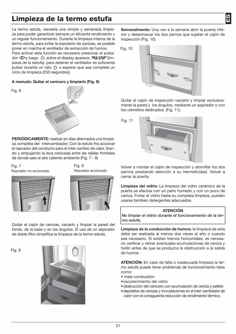
ES
Semanalmente: Una vez a la semana abrir la puerta infe-rior y desenroscar los dos pernos que sujetan el cajón de inspección (Fig. 10).
Quitar el cajón de inspección vaciarlo y limpiar exclusiva-mente la pared y los ángulos, mediante un aspirador o con los utensilios dedicados, (Fig. 11).
Volver a montar el cajón de inspección y atornillar los dos pernos prestando atención a su hermeticidad. Volver a cerrar la puerta.
Limpieza del vidrio: La limpieza del vidrio cerámico de la puerta se efectúa con un paño húmedo y con un poco de ceniza. Frotar el vidrio hasta su completa limpieza, pueden usarse también detergentes adecuados.
Limpieza de la conducción de humos: la limpieza de esta debe ser realizada al menos dos veces al año o cuando sea necesario, Si existen tramos horizontales, es necesa-rio verificar y retirar eventuales acumulaciones de ceniza y hollín antes de que se produzca la obstrucción a la salida de humos.
ATENCIÓN: En caso de falta o inadecuada limpieza la ter-mo estufa puede tener problemas de funcionamiento tales como:• mala combustión• oscurecimiento del vidrio• obstrucción del cenicero con acumulación de ceniza y pellets• depósitos de cenizas y incrustaciones en el inter cambiador de
calor con el consiguiente reducción de rendimiento térmico.
ATENCIÓNNo limpiar el vidrio durante el funcionamiento de la ter-mo estufa.
Fig. 10
Fig. 11
Limpieza de la termo estufa
51
La termo estufa, necesita una simple y esmerada limpie-za para poder garantizar siempre un eficiente rendimiento y un regular funcionamiento. Durante la limpieza interna de la termo estufa, para evitar la expulsión de cenizas, es posible poner en marcha el ventilador de extracción de humos.Para activar esta función es necesario presionar el pulsa-dor y luego , sobre el display aparece, “PUL STUF” (lim-pieza de la estufa), para detener el ventilador es suficiente pulsar durante un rato o esperar que sea complete un ciclo de limpieza (255 segundos).
A menudo: Quitar el cenicero y limpiarlo (Fig. 6)
PERIÓDICAMENTE: realizar en días alternados una limpie-za completa del intercambiador. Con la estufa fria accionar el rascador del conducto para el inter cambio de calor, tiran-do y empujando la leva colocada entre las rejillas frontales de donde sale el aire caliente ambiente (Fig. 7 - 8)
Quitar el cajón de cenizas, vaciarlo y limpiar la pared del fondo, de la base y en los ángulos. El uso de un aspirador de doble filtro simplifica la limpieza de la termo estufa.
Fig. 6
Fig. 7Rascador no accionado
Fig. 8Rascador accionado
Fig. 9
¡ATENCIÓN!Estas operaciones deben ser realizadas por un técnico calificado, o por el usuario que asumirá la responsabi-lidad, en caso de que se produzcan daños durante las operaciones de mantenimiento.El mantenimiento debe realizarse estando la estufa fría y desconectada de la electricidad. Este mantenimiento debe ser realizado por un centro de asistencia autoriza-do y es a cargo del cliente.
NOTAS
Mantenimiento extraordinario
52
Cod
. 001
041
Per informazioni e assistenza: Pour plus d'informations et de l'aide:
For information and help: Für Informationen und Hilfe:
25080 RAFFA DI PUEGNAGO D/G (BS) - Via Nazionale, 2Tel. 0365.651017 - Fax 0365.654044
[email protected] - www.lartistico.com
S.p.A.