M Zero - alan.pl · coassiale deve essere montato con molta cura: evitare curve e piegamenti....
88
M Zero 40 CH AM MOBILE TRANSCEIVER |
Transcript of M Zero - alan.pl · coassiale deve essere montato con molta cura: evitare curve e piegamenti....
M Zero
40 C H A M M O B I L E T R A N S C E I V E R |


FRANÇAIS
ESPAÑOL
DEUTSCH
ENGLISH
ITALIANO
POLSKI
M Zero Manuale d’uso | 1
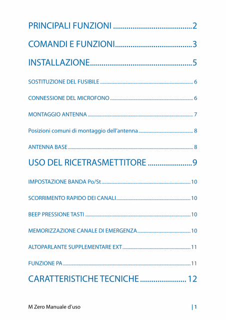
PRINCIPALI FUNZIONI .........................................2
COMANDI E FUNZIONI ........................................3
INSTALLAZIONE .....................................................5
SOSTITUZIONE DEL FUSIBILE ........................................................................... 6
CONNESSIONE DEL MICROFONO ................................................................... 6
MONTAGGIO ANTENNA ..................................................................................... 7
Posizioni comuni di montaggio dell’antenna ............................................ 8
ANTENNA BASE ..................................................................................................... 8
USO DEL RICETRASMETTITORE .......................9
IMPOSTAZIONE BANDA Po/St ........................................................................10
SCORRIMENTO RAPIDO DEI CANALI ............................................................10
BEEP PRESSIONE TASTI .....................................................................................10
MEMORIZZAZIONE CANALE DI EMERGENZA ...........................................10
ALTOPARLANTE SUPPLEMENTARE EXT .......................................................11
FUNZIONE PA .......................................................................................................11
CARATTERISTICHE TECNICHE ........................ 12
2 | M Zero Manuale d’uso
PRINCIPALI FUNZIONI• Display per la visualizzazione del canale in uso;
• Controllo RF GAIN: permette la regolazione della sensibilità del ricevi-tore. Ruotando la manopola in senso orario si ottiene un incremento della sensibilità del ricevitore; in senso antiorario si ottiene una dimi-nuzione della sensibilità (questo è utile in presenza di forti segnali ricevuti);
• Controllo SQUELCH: permette di eliminare i fastidiosi rumori di fon-do in ricezione. Per la massima sensibilità del ricevitore è preferibile che il comando sia regolato solo al preciso livello dove il rumore viene eliminato;
• Commutatore CH/EMG: permette di commutare immediatamente la radio sul canale di emergenza (il canale di emergenza può essere impostato dall’utente).
M Zero Manuale d’uso | 3
13,8V DC
PA EXTANT
9 8 7 6
1213
5
4321
10 11
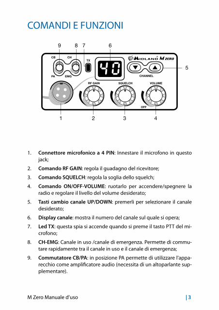
COMANDI E FUNZIONI
1. Connettore microfonico a 4 PIN: Innestare il microfono in questo jack;
2. Comando RF GAIN: regola il guadagno del ricevitore;
3. Comando SQUELCH: regola la soglia dello squelch;
4. Comando ON/OFF-VOLUME: ruotarlo per accendere/spegnere la radio e regolare il livello del volume desiderato;
5. Tasti cambio canale UP/DOWN: premerli per selezionare il canale desiderato;
6. Display canale: mostra il numero del canale sul quale si opera;
7. Led TX: questa spia si accende quando si preme il tasto PTT del mi-crofono;
8. CH-EMG: Canale in uso /canale di emergenza. Permette di commu-tare rapidamente tra il canale in uso e il canale di emergenza;
9. Commutatore CB/PA: in posizione PA permette di utilizzare l’appa-recchio come amplificatore audio (necessita di un altoparlante sup-plementare).
4 | M Zero Manuale d’uso
13,8V DC
PA EXTANT
9 8 7 6
1213
5
4321
10 11
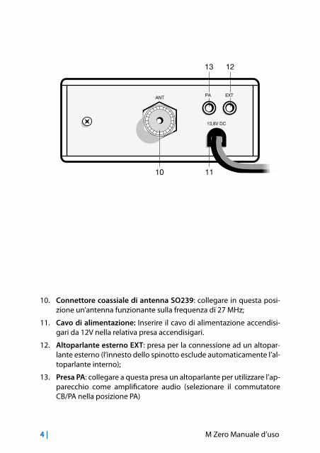
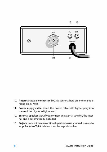
10. Connettore coassiale di antenna SO239: collegare in questa posi-zione un’antenna funzionante sulla frequenza di 27 MHz;
11. Cavo di alimentazione: Inserire il cavo di alimentazione accendisi-gari da 12V nella relativa presa accendisigari.
12. Altoparlante esterno EXT: presa per la connessione ad un altopar-lante esterno (l’innesto dello spinotto esclude automaticamente l’al-toparlante interno);
13. Presa PA: collegare a questa presa un altoparlante per utilizzare l’ap-parecchio come amplificatore audio (selezionare il commutatore CB/PA nella posizione PA)
M Zero Manuale d’uso | 5
Rondelle
Rondelle
Rondelle
Rondelle
Viti
Viti
Vite
Staffa
Dadi
Dadi
Viti e rondelle
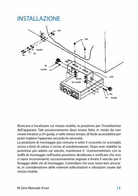
INSTALLAZIONE
Ricercare e localizzare sul mezzo mobile, la posizione per l’installazione dell’apparato. Tale posizionamento deve essere fatto in modo da non creare intralcio a chi guida, e nello stesso tempo, di facile accessibilità per poter togliere l’apparato secondo le necessità.La posizione di montaggio più comune è sotto il cruscotto (si sconsiglia vicino a fonti di calore o vicino al condizionatore). Dopo aver stabilito la posizione più adatta sul veicolo, mantenere il ricetrasmettitore con la staffa di montaggio nell’esatta posizione desiderata e verificare che non ci siano inconvenienti; successivamente segnare e forare il veicolo per il fissaggio delle viti di montaggio. Controllare che esse siano ben ancora-te, in considerazione delle notevoli sollecitazioni e vibrazioni create dal mezzo mobile.
6 | M Zero Manuale d’uso
13,8V DC
PA EXTANT
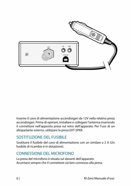
Inserire il cavo di alimentazione accendisigari da 12V nella relativa presa accendisigari. Prima di operare, installare e collegare l’antenna inserendo il connettore nell’apposita presa sul retro dell’apparato. Per l’uso di un altoparlante esterno, utilizzare la presa EXT-SPKR.
SOSTITUZIONE DEL FUSIBILESostituire il fusibile del cavo di alimentazione con un similare a 2 A (Un fusibile di ricambio è in dotazione).
CONNESSIONE DEL MICROFONOLa presa del microfono è situata sul davanti dell’apparato. Accertarsi sempre che il connettore sia ben connesso alla presa.

M Zero Manuale d’uso | 7
MONTAGGIO ANTENNAL’antenna è l’elemento più importante per ottenere i migliori risultati. È in-dispensabile che l’antenna abbia un’impedenza di 50 Ohm. A seconda della posizione in cui viene installata, il rendimento varia notevolmente. Usare un cavo coassiale con impedenza 50 Ohm. Sono consigliati i cavi RG 58U per lunghezza sotto i 2.5 metri, oppure RG 8 per lunghezze superiori. Il cavo coassiale deve essere montato con molta cura: evitare curve e piegamenti. Inoltre va ricordato che il cavo più corto aumenta la sensibilità dell’apparato, così pure un cattivo collegamento tra apparato e antenna.
Consigli:• Montare l’antenna nel posto più libero e più alto dell’auto.
• L’antenna deve essere installata in posizione verticale, e così deve ri-manere anche quando il veicolo è in moto.
• Montare l’antenna e il cavo il più possibile lontano da fonti di rumore.
• La massa dell’antenna deve coprire un’area di 1m2.
Esistono in commercio diversi tipi di antenna: con stilo a 1/4 d’onda; alimen-tate al centro; con carica in base; con carica in alto. Le antenne caricate sono più corte, ma per un miglior rendimento si consigliano quelle di lunghezza di circa 2 metri.L’installazione a centro tetto è la migliore in senso assoluto perché il ground o radiale di terra è proporzionale in tutte le direzioni, mentre su una fiancata o in una qualsiasi altra parte del veicolo, diventa proporzionale alla massa dello stesso (es: se l’antenna è installata posteriormente, diventa direttiva in avanti, cioè i segnali provenienti dalla parte opposta sono meglio ricevuti, così dicasi anche per quelli trasmessi).
N.B.: con l’ausilio di un accoppiatore a due vie, l’antenna montata anterior-mente può sostituire l’antenna della radio FM.
8 | M Zero Manuale d’uso
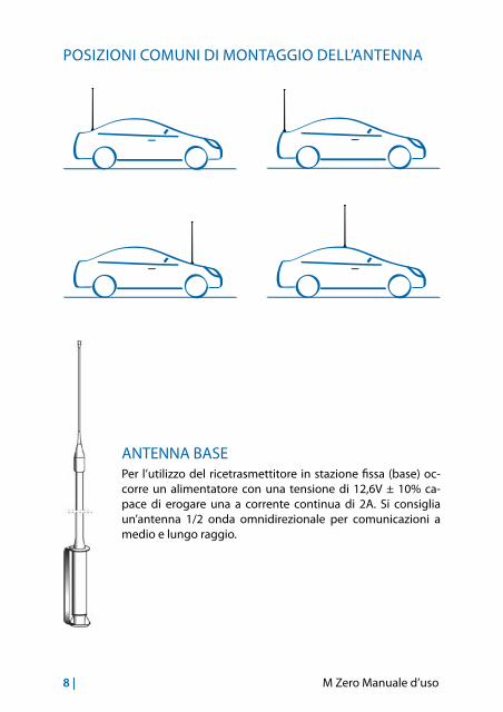
POSIZIONI COMUNI DI MONTAGGIO DELL’ANTENNA
ANTENNA BASEPer l’utilizzo del ricetrasmettitore in stazione fissa (base) oc-corre un alimentatore con una tensione di 12,6V ± 10% ca-pace di erogare una a corrente continua di 2A. Si consiglia un’antenna 1/2 onda omnidirezionale per comunicazioni a medio e lungo raggio.
M Zero Manuale d’uso | 9
USO DEL RICETRASMETTITORERicezione
1. Assicurarsi che la presa accendisigari sia inserita nell’apposita presa a 12V.
2. Controllare che l’antenna e il microfono siano ben connessi.
3. Posizionare il commutatore d’emergenza sulla posizione CH.
4. Girare la manopola squelch nella massima posizione antioraria.
5. Accendere l’apparato mediante la manopola VOLUME.
6. Girare la manopola RF GAIN nella massima posizione oraria.
7. Ricercare il canale desiderato attraverso i tasti CHANNEL.
8. Regolare il volume come desiderato.
9. Regolare lo squelch. Questo comando viene utilizzato per eliminare il rumore di fondo del ricevitore in assenza di segnali d’ingresso. Per la massima sensibilità del ricevitore è preferibile che il comando sia regolato solo al preciso livello dove il rumore di fondo del ricevitore o il rumore ambientale, viene eliminato. Girare completamente in senso antiorario poi lentamente in senso orario finché non scom-parirà il rumore. Qualsiasi segnale affinché possa venir ricevuto, do-vrà essere leggermente più intenso rispetto alla media del rumore ricevuto. Un’ulteriore rotazione in senso orario aumenterà il livello di soglia che il segnale dovrà superare per poter essere udito. Se lo squelch sarà posizionato nella massima posizione in senso orario, si potranno sentire solo segnali molto forti.
Trasmissione
1. Selezionare il canale desiderato.
2. Premere il pulsante di trasmissione sul microfono, parlare mante-nendo una distanza dalle labbra dai 5 a 8 cm.
3. Per ricevere, rilasciare il pulsante di trasmissione.
N.B.: gridare nel microfono non aumenta la portata della trasmissione, in quanto un circuito interno automaticamente commuta la massima mo-dulazione. Si consiglia quindi di usare un tono di voce normale.
10 | M Zero Manuale d’uso
IMPOSTAZIONE BANDA Po/St1. Premere e tenere premuto i tasti UP/DOWN mentre si accende l’ap-
parecchio;
2. Premere UP o DOWN per selezionare la banda desiderata: Po = Polonia (40 Ch AM - 26.960/27.400) - St =Europa (40 CH AM - 26.965/27.405)
3. Premere PTT per uscire dalla selezione.
SCORRIMENTO RAPIDO DEI CANALIPer scorrere velocemente i canali, tenere premuto per circa 6 secondi il tasto UP o DOWN.
BEEP PRESSIONE TASTIQuando questa funzione é attiva la radio emette un beep audio ogni vol-ta che si preme un tasto.Per abilitare/disabilitare il beep:
1. tenere premuto il tasto UP ed accendere la radio;
2. rilasciare e premere i tasti UP o DOWN per abilitare o disabilitare il beep;
3. il display mostrerà ‘ON’ quando il beep è attivo o ‘OF’ quando il beep è disattivato.
MEMORIZZAZIONE CANALE DI EMERGENZAIl canale di emergenza impostato di default è il 19; per cambiare il canale operare come segue:
1. spostare il comando CH/EMG nella posizione EMG;
2. sul display lampeggia il canale di emergenza attuale;
3. premere contemporaneamente i tasti UP e DOWN per circa 5 secon-di. Il display smette di lampeggiare;
4. selezionare il nuovo canale di emergenza con i tasti UP e DOWN;
5. premere nuovamente i due tasti UP e DOWN per circa 5 secondi;
6. il display lampeggerà nuovamente ed indicherà il canale di emer-genza memorizzato.
M Zero Manuale d’uso | 11
ALTOPARLANTE SUPPLEMENTARE EXTInserire un altoparlante con potenza da 3 a 10 Watt nella presa EXT. Il collegamento ad un altoparlante esterno esclude automaticamente quello interno.
FUNZIONE PALa funzione PA permette di utilizzare l’apparato come amplificatore au-dio. 1. Inserire un altoparlante con potenza da 3 a 10 Watt nella presa PA,
2. posizionare il commutatore CB/PA nella posizione PA,
3. premere il tasto PTT del microfono e parlare.
12 | M Zero Manuale d’uso
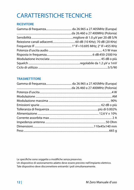
CARATTERISTICHE TECNICHERICEVITORE
Gamma di frequenza..................................... da 26.965 a 27.405MHz (Europa)...............................................................................da 26.460 a 27.400MHz (Polonia)Sensibilità ............................................................migliore di 1.0 µV per 20 dB S/NReiezione canali adiacenti ................................60 dB (10 KHz); 70 dB (20 KHz)Frequenze IF ..................................................... 1° IF=10.695 MHz; 2° IF=455 KHzPotenza d’uscita audio ............................................................................. 4.5 W maxRisposta in frequenza..................................................................6 dB:450-2500 HzModulazione incrociata ......................................................................... 45 dB o piùSquelch ..........................................................................regolabile da 1.2 µV a 1mVCiclo di utilizzo ....................................................................................................5/5/90
TRASMETTITORE
Gamma di frequenza..................................... da 26.965 a 27.405MHz (Europa)...............................................................................da 26.460 a 27.400MHz (Polonia)Potenza d’uscita ........................................................................................................4 WModulazione .............................................................................................................. AMModulazione massima ......................................................................................... 90%Emissioni spurie ........................................................................................ 62 dB o piùTolleranza di frequenza ......................................................................più di 0.002%Alimentazione ........................................................................................ 12,6 V ± 10%Corrente assorbita max .......................................................................................... 2 AImpedenza antenna .......................................................................................50 OhmDimensioni ........................................................................................110x45x140 mmPeso ...........................................................................................................................665 g
Le specifiche sono soggette a modifiche senza preavviso.Un dispositivo di sezionamento adatto deve essere previsto nell’impianto elettrico.Tale dispositivo deve disconnettere entrambi i poli simultaneamente.

M Zero Instruction Guide | 1
MAIN FUNCTIONS ................................................2
CONTROLS AND FUNCTIONS ..........................3
INSTALLATION ........................................................5
REPLACING FUSE .................................................................................................. 6
CONNECTING THE MICROPHONE ................................................................... 6
BASE STATION ANTENNA ................................................................................... 9
USING YOUR TRANSCEIVER ...............................9
SELECTION OF Po/St BANDS ..........................................................................10
QUICK SCROLL ...................................................................................................10
KEYPAD BEEP .......................................................................................................11
EMERGENCY CHANNEL MEMORY ................................................................11
EXTERNAL SPEAKER ...........................................................................................11
PA FUNCTION .......................................................................................................11
TECHNICAL SPECIFICATIONS ......................... 12

2 | M Zero Instruction Guide
MAIN FUNCTIONS• Display showing the channel in use;
• RF GAIN: adjusts the rx sensitivity. By turning the knob clockwise the rx sensitivity will increase; by turning counter-clockwise it will be re-duced (this is very helpful in case of strong signals received);
• SQUELCH: the squelch eliminates the background noise in rx. To get the best sensitivity in rx the squelch should be adjusted exactly at the level when the background noise disappears;
• CH/EMG: this knob allows to switch immediately to the emergency channel. The emergency channel can be set by the user.
M Zero Instruction Guide | 3
13,8V DC
PA EXTANT
9 8 7 6
1213
5
4321
10 11
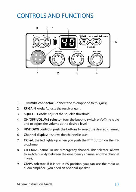
CONTROLS AND FUNCTIONS
1. PIN mike connector: Connect the microphone to this jack;
2. RF GAIN knob: Adjusts the receiver gain;
3. SQUELCH knob: Adjusts the squelch threshold;
4. ON/OFF-VOLUME selector: turn the knob to switch on/off the radio and to adjust the volume at the desired level;
5. UP/DOWN controls: push the buttons to select the desired channel;
6. Channel display: it shows the channel in use;
7. TX led: the led lights up when you push the PTT button on the mi-crophone;
8. CH-EMG: Channel in use /Emergency channel. This selector allows to switch quickly between the emergency channel and the channel in use;
9. CB/PA selector: if it is set in PA position, you can use the radio as audio amplifier (you need an optional speaker).
4 | M Zero Instruction Guide
13,8V DC
PA EXTANT
9 8 7 6
1213
5
4321
10 11
10. Antenna coaxial connector SO239: connect here an antenna ope-rating on 27 MHz;
11. Power supply cable: insert the power cable with lighter plug into the vehicle’s cigarette lighter cord.
12. External speaker jack. If you connect an external speaker, the inter-nal one is automatically excluded.
13. PA jack: connect here an optional speaker to use your radio as audio amplifier (the CB/PA selector must be in position PA)
M Zero Instruction Guide | 5
INSTALLATION
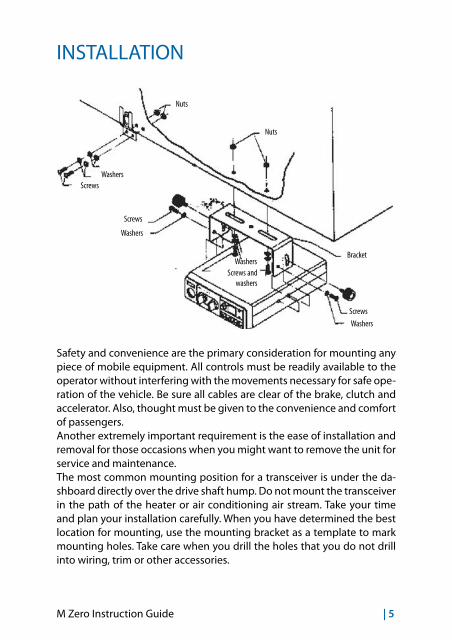
Safety and convenience are the primary consideration for mounting any piece of mobile equipment. All controls must be readily available to the operator without interfering with the movements necessary for safe ope-ration of the vehicle. Be sure all cables are clear of the brake, clutch and accelerator. Also, thought must be given to the convenience and comfort of passengers.Another extremely important requirement is the ease of installation and removal for those occasions when you might want to remove the unit for service and maintenance.The most common mounting position for a transceiver is under the da-shboard directly over the drive shaft hump. Do not mount the transceiver in the path of the heater or air conditioning air stream. Take your time and plan your installation carefully. When you have determined the best location for mounting, use the mounting bracket as a template to mark mounting holes. Take care when you drill the holes that you do not drill into wiring, trim or other accessories.
Washers
Washers
Washers
Washers
Screws
Screws
Screws
Bracket
Nuts
Nuts
Screws and washers
6 | M Zero Instruction Guide
13,8V DC
PA EXTANT
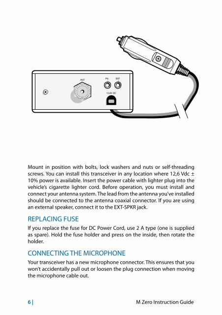
Mount in position with bolts, lock washers and nuts or self-threading screws. You can install this transceiver in any location where 12,6 Vdc ± 10% power is available. Insert the power cable with lighter plug into the vehicle’s cigarette lighter cord. Before operation, you must install and connect your antenna system. The lead from the antenna you’ve installed should be connected to the antenna coaxial connector. If you are using an external speaker, connect it to the EXT-SPKR jack.
REPLACING FUSEIf you replace the fuse for DC Power Cord, use 2 A type (one is supplied as spare). Hold the fuse holder and press on the inside, then rotate the holder.
CONNECTING THE MICROPHONEYour transceiver has a new microphone connector. This ensures that you won’t accidentally pull out or loosen the plug connection when moving the microphone cable out.

M Zero Instruction Guide | 7
ANTENNA SYSTEMA mobile antenna system is not limited only to the antenna. The transmis-sion line as well as the vehicle are important factors in the total antenna system. Therefore, you must use the correct type of transmission line and mount the antenna securely in a position that will give you optimal re-sults. Use coaxial cable with an impedance of 50 Ohms. We suggest type RG 58/U for lengths under 2.5 m or RG 8/U for longer lengths. Generally speaking, you should keep the length of the transmission line to a mi-nimum. The above discussion is as important for reception as for the transmission. If a mismatch exists between the antenna and the receiver, the excellent sensitivity and signal-to-noise radio of the receiver circuit will be defeated.
Suggestions A few general rules should help you to install any mobile antenna pro-perly.• Keep it as far as possible from the main bulk of the vehicle.• During operation, it must be vertical, and rigid enough to remain ver-
tical when the vehicle or boat is in motion.• Mount it as far as possible from sources of noise (ignition system,
gauges, etc.) and keep the transmission line away from these noise sources.
• An antenna mounted in a boat requires a good ground connection. This can be either a metal hull or a ground made of tin-foil or copper sheeting.
This ground should cover an area of at least 1 m2 or more. Be sure the transceiver also has an adequate ground. There are many types of mobile CB antennas: a full quarter-wave length whip, a centerloaded whip, top loaded whip and the base loaded type are typical. A vertically polarized whip antenna is best suited for mobile service. It is omnidirectional. If it’s the loaded type, you will find it a physically shorter antenna. But, for gre-ater efficiency the 2.5 m long, full quarter-wave whip is better. Antenna length is directly related to efficiency.Generally, the longer it is, the more efficient will be.
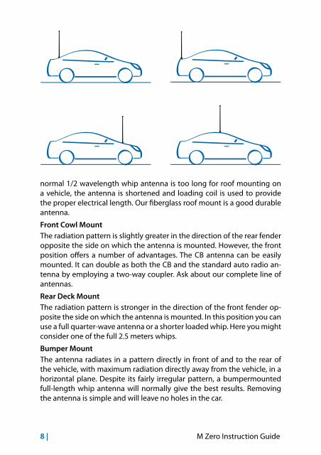
There are many possible antenna locations on a car. Four of the most popular are shown and discussed on the following.Roof Mount In this position the antenna radiates equally in all directions. Since the
8 | M Zero Instruction Guide
normal 1/2 wavelength whip antenna is too long for roof mounting on a vehicle, the antenna is shortened and loading coil is used to provide the proper electrical length. Our fiberglass roof mount is a good durable antenna.
Front Cowl Mount The radiation pattern is slightly greater in the direction of the rear fender opposite the side on which the antenna is mounted. However, the front position offers a number of advantages. The CB antenna can be easily mounted. It can double as both the CB and the standard auto radio an-tenna by employing a two-way coupler. Ask about our complete line of antennas.
Rear Deck Mount The radiation pattern is stronger in the direction of the front fender op-posite the side on which the antenna is mounted. In this position you can use a full quarter-wave antenna or a shorter loaded whip. Here you might consider one of the full 2.5 meters whips.
Bumper Mount The antenna radiates in a pattern directly in front of and to the rear of the vehicle, with maximum radiation directly away from the vehicle, in a horizontal plane. Despite its fairly irregular pattern, a bumpermounted full-length whip antenna will normally give the best results. Removing the antenna is simple and will leave no holes in the car.
M Zero Instruction Guide | 9
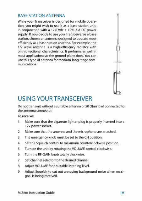
BASE STATION ANTENNAWhile your Transceiver is designed for mobile opera-tion, you might wish to use it as a base station unit, in conjunction with a 12,6 Vdc ± 10% 2 A DC power supply. If you decide to use your Transceiver as a base station, choose an antenna designed to operate most efficiently as a base station antenna. For example, the 1/2 wave antenna is a high-efficiency radiator with omnidirectional characteristics. It performs as well in most applications as the ground plane does. You can use this type of antenna for medium-long range com-munications.
USING YOUR TRANSCEIVERDo not transmit without a suitable antenna or 50 Ohm load connected to the antenna connector.
To receive:
1. Make sure that the cigarette lighter plug is properly inserted into a 12V power socket.
2. Make sure that the antenna and the microphone are attached.
3. The emergency knob must be set to the CH position.
4. Set the Squelch control to maximum counterclockwise position.
5. Turn on the unit by rotating the VOLUME control clockwise.
6. Turn the RF-GAIN knob totally clockwise.
7. Set channel selector to the desired channel.
8. Adjust VOLUME for a suitable listening level.
9. Adjust Squelch to cut out annoying background noise when no si-gnal is being received.

10 | M Zero Instruction Guide
To do this, set the Channel Selector to a channel where no signals are pre-sent or wait until signals cease on your channel. Then, rotate the Squelch control in a clockwise direction to the point where the background noise just stops. Now, when a signal is present, you will hear it, but will not be di-sturbed by noise on the channel between signals. When properly set, the Squelch keeps the receiver “dead” until a signal comes in on that channel. However, do not set the Squelch too high, or weak signals will not be able to open the Squelch circuit. To receive very weak signals, it is best to leave Squelch set to the minimum position by rotating the control maximum counterclockwise. The Squelch circuit in your transceiver is an advanced design. It uses an operational amp IC to accomplish a hysteresis action. The result is that when you set the Squelch for a precise signal level, if that signal level increases or decreases in strength, the Squelch circuit will follow this change. With conventional Squelch circuit, often a signal which changes strength get “chopped” by the Squelch circuit and you lose a por-tion of the message. With a hysteresis Squelch, you get it all.
To Transmit:
1. Select the desired channel.
2. Press the push-to talk button on the microphone and hold it an an-gle about 5-7 cm from your mouth and speak in a normal voice.
3. To receive, release the push-to-talk button. Be sure the mic plug is firmly connected to the jack.
NOTE: shouting into the mic will not increase your power or signal. An in-ternal circuit automatically sets the mic signal for maximum modulation, so speak loudly will give no advantage.
SELECTION OF Po/St BANDS1. Turn on the radio while keeping pressed the UP/DOWN controls
2. With the UP / DOWN buttons select the desired band: Po = Poland (40 Ch AM - 26.960/27.400) - St =Europe (40 CH AM - 26.965/27.405)
3. Push PTT to exit the selection
QUICK SCROLL To scroll the channels, keep pressed the UP or DOWN controls for 6 se-conds.
M Zero Instruction Guide | 11
KEYPAD BEEP When this function is enabled, you will hear a beep tone everytime a but-ton is pressed. To activate/deactivate the beep tone: 1. keep pressed the UP button while turning on the radio;
2. press UP or DOWN to enable/disable the beep;
3. when the beep tone is enabled, the display will show ‘ON’ and when it’s disabled, ‘OF’ will be displayed.
EMERGENCY CHANNEL MEMORY The emergency channel set by default is channel 19; to change it, follow these steps:1. move the knob of the CH/EMG selector to EMG position;
2. the current emergency channel blinks on the display;
3. press the UP / DOWN controls for 5 seconds at the same time. The display will stop blinking;
4. with the UP/DOWN buttons select the new emergency channel;
5. push again UP / DOWN for about 5 seconds;
6. the display will blink again and will indicate the new emergency channel memory.
EXTERNAL SPEAKERConnect a speaker with a power of 3-10 Watt to the EXT jack. When you connect an external speaker to the radio, the internal speaker is automatically disconnected.
PA FUNCTIONThe PA function allows you to use the radio as an audio amplifier. 1. Connect a speaker with a power of 3-10 Watt to the PA jack;
2. move the CB/PA knob in PA position;
3. press the PTT button of the microphone and talk.
12 | M Zero Instruction Guide
TECHNICAL SPECIFICATIONS
RECEIVERFrequency coverage ..........................................26.965 to 27.405 MHz (Europe)...................................................................................26.960 to 27.400 MHz (Poland)Sensitivity .....................................................better than 1.0 µV for 20 dB SINADAdjacent Channel Rejection ...................... 60 dB at 10 kHz; 70 dB for 20 KHzIntermediate Frequency ........................ 1st IF=10.695 MHz; 2nd IF=455 KHzAudio Output power .......................................................................... 4.5 watts maxFrequency Response (6dB) .................................................................450-2500 HzCross Modulation ..............................................................................45 dB or betterSquelch .................................................................. adjustable from 1.2 µV to 1mVDuty cycle..............................................................................................................5/5/90
TRANSMITTERFrequency coverage ..........................................26.965 to 27.405 MHz (Europe)...................................................................................26.960 to 27.400 MHz (Poland)Output Power ............................................................................................................4 WType of modulation ................................................................................................. AMMax modulation ..................................................................................................... 90%Spurious Radiation ............................................................................62 dB or betterFrequency Tolerance ................................................................better than 0.002%Antenna impedance .......................................................................................50 OhmPower supply ..................................................................................12,6 V ± 10%maxMax Current Drain .................................................................................................... 2ADimensions .......................................................................................110x45x140 mmWeight ......................................................................................................................665 g
Specifications are subject to change without notice.A readily accessible disconnect device shall be incorporated in the installation wiring.The disconnect device shall disconnect both poles simultaneously.

M Zero Bedienungsanleitung | 1
HAUPTFUNKTIONEN ..........................................2
BEDIENUNG UND FUNKTIONEN ...................3
INSTALLATION ......................................................5
MIKROFONANSCHLUSS .................................................................................... 7
MONTAGE DER ANTENNE ................................................................................ 7
EMPFEHLUNGEN .................................................................................................. 7
FESTSTATION ......................................................................................................... 8
BEDIENUNG IHRES FUNKGERÄTES ...............9
AUSWAHL DER PO / ST BÄNDER .................................................................10
QUICK SCROLL ...................................................................................................10
TASTENTON .........................................................................................................10
NOTRUFKANAL-SPEICHER .............................................................................10
EXTERNER LAUTSPRECHER ...........................................................................11
PA FUNKTION ......................................................................................................11
TECHNISCHE DATEN ........................................ 12
2 | M Zero Bedienungsanleitung
HAUPTFUNKTIONEN• Das Display zeigt den aktiven Kanal
• RF Gain: Einstellung der Empfangsempfindlichkeit ein. Durch Drehen des Knopfes im Uhrzeigersinn wird die Empfindlichkeit erhöht, gegen den Uhrzeigersinn wird diese reduziert (dieses ist sehr hilfreich beim Empfang starker Signale)
• Squelch: Rauschsperre zur Unterdrückung der Hintergrundgeräusche beim Empfang. Für beste Empfangsempfindlichkeit, die Rauschsperre nur so hoch einstellen, dass die Hintergrundgeräusche gerade ausge-blendet werden;
• CH/EMG: Mit diesem Schalter kann direkt auf den Notrufkanal umge-schaltet werden. Der Notrufkanal kann durch den Benutzer einge-stellt werden.
M Zero Bedienungsanleitung | 3
13,8V DC
PA EXTANT
9 8 7 6
1213
5
4321
10 11
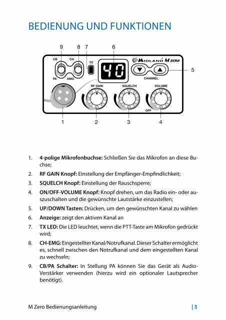
BEDIENUNG UND FUNKTIONEN
1. 4-polige Mikrofonbuchse: Schließen Sie das Mikrofon an diese Bu-chse;
2. RF GAIN Knopf: Einstellung der Empfänger-Empfindlichkeit;
3. SQUELCH Knopf: Einstellung der Rauschsperre;
4. ON/OFF-VOLUME Knopf: Knopf drehen, um das Radio ein- oder au-szuschalten und die gewünschte Lautstärke einzustellen;
5. UP/DOWN Tasten: Drücken, um den gewünschten Kanal zu wählen
6. Anzeige: zeigt den aktiven Kanal an
7. TX LED: Die LED leuchtet, wenn die PTT-Taste am Mikrofon gedrückt wird;
8. CH-EMG: Eingestellter Kanal/Notrufkanal. Dieser Schalter ermöglicht es, schnell zwischen den Notrufkanal und dem eingestellten Kanal zu wechseln;
9. CB/PA Schalter: In Stellung PA können Sie das Gerät als Audio-Verstärker verwenden (hierzu wird ein optionaler Lautsprecher benötigt).
4 | M Zero Bedienungsanleitung
13,8V DC
PA EXTANT
9 8 7 6
1213
5
4321
10 11
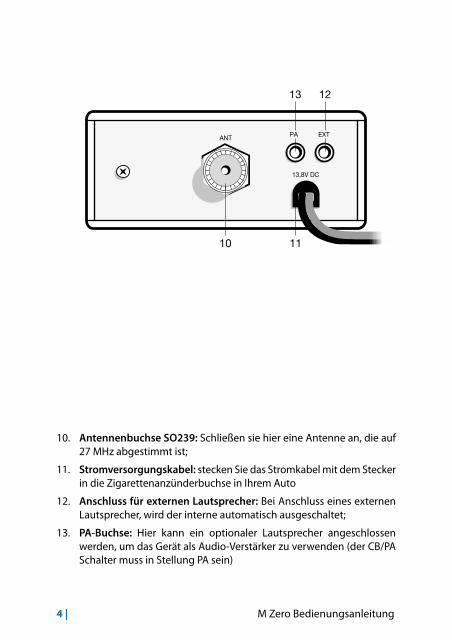
10. Antennenbuchse SO239: Schließen sie hier eine Antenne an, die auf 27 MHz abgestimmt ist;
11. Stromversorgungskabel: stecken Sie das Stromkabel mit dem Stecker in die Zigarettenanzünderbuchse in Ihrem Auto
12. Anschluss für externen Lautsprecher: Bei Anschluss eines externen Lautsprecher, wird der interne automatisch ausgeschaltet;
13. PA-Buchse: Hier kann ein optionaler Lautsprecher angeschlossen werden, um das Gerät als Audio-Verstärker zu verwenden (der CB/PA Schalter muss in Stellung PA sein)

M Zero Bedienungsanleitung | 5
INSTALLATION
Bei einem Fahrzeug-Einbau ist darauf zu achten, dass die Beinfreiheit des Fahrers nicht eingeschränkt wird und alle Bedienelemente wie Schaltknüppel oder Handbremse ohne Kabelverwirrungen zugänglich sind. Eine Montage des Gerätes am Fahrzeug-Himmel ist verkehrsrecht-lich verboten (Ausnahme: LKWs mit Montagemöglichkeit unter dem Dach). Das Gerät darf nicht über längere Zeit direkter Sonnenein-strahlung ausgesetzt sein, da es sich sonst zu stark erwärmen könnte! Aus dem selben Grund darf es nicht in der Nähe der Austrittsöffnungen für die Heizluft montiert werden. Überlicherweise wird das Funkgerät un-ter dem Armaturenbrett montiert.
Unterlegscheiben
Unterlegscheiben
Unterlegscheiben
Schrauben
Schrauben
Schrauben
Bügel
Muttern
Muttern
Schrauben undUnterlegscheiben

6 | M Zero Bedienungsanleitung
13,8V DC
PA EXTANT
Benutzen Sie die beiliegende Mobilhalterung als Bohrschablone und markieren Sie die beiden Befestigungspunkte. Achten Sie darauf, dass bei der Montage an dieser Stelle keine Bauteile oder Kabel hinter dem Ar-maturenbrett beschädigt werden! Bohren Sie mit einem Bohrer die bei-den Löcher zur Befestigung der Mobilhalterung. Schrauben Sie dann die Mobilhalterung mit den beiliegenden Schrauben fest. Befestigen Sie das Funkgerät so in der Mobilhalterung, dass die Rückseite des Funkgerätes für die weiteren Anschlüsse zugänglich bleibt. Nach dem Anschluss der Stromversorgung und der Antenne sowie eines eventuellen externen Lautsprechers fixieren Sie das Funkgerät in der Mobilhalterung: Ziehen Sie die seitlichen Rändelschrauben in der gewünschten Position fest. Ihr M ZERO wird mit 12,6+/-10% Gleichspannung betrieben.Stecken Sie den Stecker der Versorgungsleitung in die Zigarettenanzün-der-Buchse des Fahrzeugs.

M Zero Bedienungsanleitung | 7
ERSATZSICHERUNGSollte es einmal zu einem Kurzschluss kommen, können Sie die durchge-brannte Sicherung durch die im Lieferumfang befindliche 2 A Sicherung austauschen.
MIKROFONANSCHLUSSDer Mikrofonstecker ist mit einer Schraube ausgestattet, die ein unbeab-sichtigtes Lösen vom Gerät verhindert.
MONTAGE DER ANTENNEDie Antenne stellt das wichtigste Element einer Funkstation dar, und entscheidet im Wesentlichen über die Reichweite. Der Antennenan-schluss Ihres M Zero weist eine Impedanz von 50 Ohm auf. Sie müssen eine CB-Mobilantenne mit derselben Impedanz verwenden und diese über ein Koaxialkabel (ebenfalls mit 50 Ohm Impedanz) mit der Anten-nenbuchse des Funkgerätes verbinden. Wir empfehlen die Kabel RG 58U für Distanzen unter 2,50 m und RG 8 für größere Distanzen. Das Koa-xialkabel muss sorgfältig verlegt werden: vermeiden Sie Verdrehungen oder Knicke im Kabel. Allgemein gilt die Regel, je kürzer das Kabel, um so besser der Empfang.
EMPFEHLUNGENFür die Leistungsfähigkeit einer Antenne ist auch der Ort der Montage wichtig. Bitte beachten Sie hierbei folgende Punkte:Idealerweise wird eine Mobilantenne auf dem Autodach in der Wa-genmitte montiert, es bieten sich aber auch der Kotflügel, der Koffer-raumdeckel oder die Regenrinne an.Montieren Sie die Antenne so hoch wie möglich.Montieren Sie die Antenne möglichst in der Mitte einer ebenen Me-tallfläche.Montieren Sie die Antenne nicht in der Nähe interner Störquellen wie z. B. Zündanlagen oder Scheibenwischermotoren.Der beste Platz für die Antenne ist auf dem Fahrzeugdach. Sollte hier eine Montage schwierig sein, so gibt es auch noch andere Montagemögli-chkeiten, die eine gute Abstrahlung sicherstellen.Im Handel sind verschiedene Antennentypen erhältlich. Für die Auto-Montage verwendet man verkürzte Antennen, welche entweder am Fußpunkt oder in der Mitte eine Spule zur elektrischen Verlängerung
8 | M Zero Bedienungsanleitung
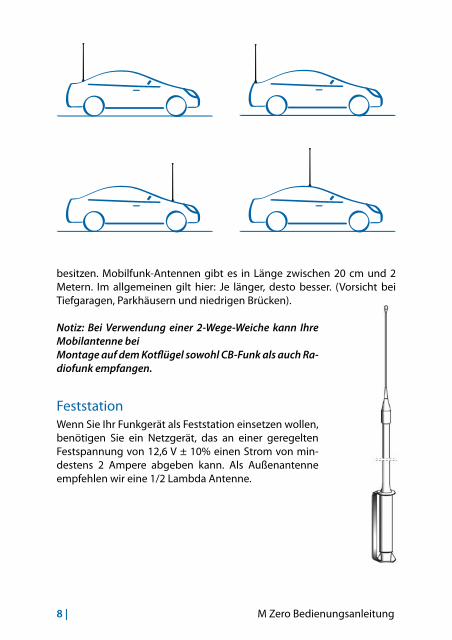
besitzen. Mobilfunk-Antennen gibt es in Länge zwischen 20 cm und 2 Metern. Im allgemeinen gilt hier: Je länger, desto besser. (Vorsicht bei Tiefgaragen, Parkhäusern und niedrigen Brücken).
Notiz: Bei Verwendung einer 2-Wege-Weiche kann Ihre Mobilantenne bei Montage auf dem Kotflügel sowohl CB-Funk als auch Ra-diofunk empfangen.
FeststationWenn Sie Ihr Funkgerät als Feststation einsetzen wollen, benötigen Sie ein Netzgerät, das an einer geregelten Festspannung von 12,6 V ± 10% einen Strom von min-destens 2 Ampere abgeben kann. Als Außenantenne empfehlen wir eine 1/2 Lambda Antenne.
M Zero Bedienungsanleitung | 9
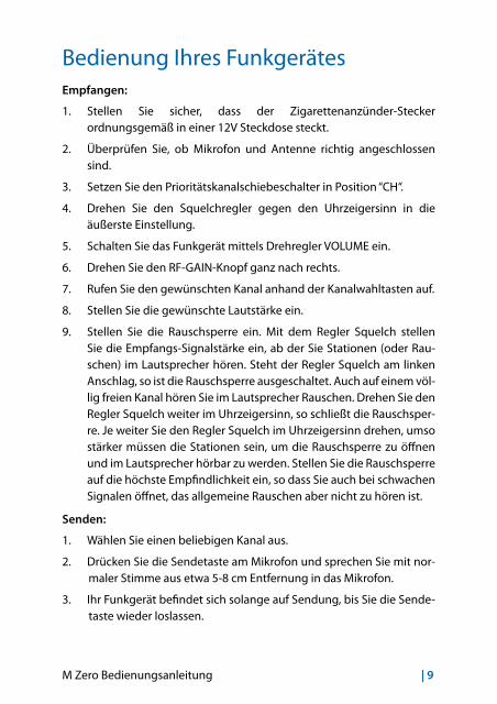
Bedienung Ihres FunkgerätesEmpfangen:
1. Stellen Sie sicher, dass der Zigarettenanzünder-Stecker ordnungsgemäß in einer 12V Steckdose steckt.
2. Überprüfen Sie, ob Mikrofon und Antenne richtig angeschlossen sind.
3. Setzen Sie den Prioritätskanalschiebeschalter in Position “CH“.
4. Drehen Sie den Squelchregler gegen den Uhrzeigersinn in die äußerste Einstellung.
5. Schalten Sie das Funkgerät mittels Drehregler VOLUME ein.
6. Drehen Sie den RF-GAIN-Knopf ganz nach rechts.
7. Rufen Sie den gewünschten Kanal anhand der Kanalwahltasten auf.
8. Stellen Sie die gewünschte Lautstärke ein.
9. Stellen Sie die Rauschsperre ein. Mit dem Regler Squelch stellen Sie die Empfangs-Signalstärke ein, ab der Sie Stationen (oder Rau-schen) im Lautsprecher hören. Steht der Regler Squelch am linken Anschlag, so ist die Rauschsperre ausgeschaltet. Auch auf einem völ-lig freien Kanal hören Sie im Lautsprecher Rauschen. Drehen Sie den Regler Squelch weiter im Uhrzeigersinn, so schließt die Rauschsper-re. Je weiter Sie den Regler Squelch im Uhrzeigersinn drehen, umso stärker müssen die Stationen sein, um die Rauschsperre zu öffnen und im Lautsprecher hörbar zu werden. Stellen Sie die Rauschsperre auf die höchste Empfindlichkeit ein, so dass Sie auch bei schwachen Signalen öffnet, das allgemeine Rauschen aber nicht zu hören ist.
Senden:
1. Wählen Sie einen beliebigen Kanal aus.
2. Drücken Sie die Sendetaste am Mikrofon und sprechen Sie mit nor-maler Stimme aus etwa 5-8 cm Entfernung in das Mikrofon.
3. Ihr Funkgerät befindet sich solange auf Sendung, bis Sie die Sende-taste wieder loslassen.
10 | M Zero Bedienungsanleitung
Notiz: Schreien in das Mikrofon erhöht nicht die Reichweite. Ein integrier-ter Schaltkreis regelt die max. Wiedergabelautstärke. Es wird empfohlen mit normaler Lautstärke in das Mikrofon zu sprechen.
AUSWAHL DER Po / St BÄNDER1. Schalten Sie das Radio ein, während Sie die UP/DOWN-Tasten ge-
drückt halten
2. Mit den UP/DOWN-Tasten das gewünschte Band auswählen: Po = Polen (40 K AM - 26,960 / 27,400) - St = Europa (40 K AM - 26,965 / 27,405)
3. PTT drücken, um die Auswahl zu beenden
QUICK SCROLL Um schnell durch die Kanäle zu scrollen, die UP- oder DOWN-Taste für 6 Sekunden gedrückt halten.
Tastenton Wenn diese Funktion aktiviert ist, werden Sie einen Signalton hören, je-des Mal, wenn eine Taste gedrückt wird. Aktivierung/Deaktivierung des Signaltons:1. UP-Taste gedrückt halten, während Sie das Gerät einschalten;
• Drücken Sie zum Ein-/Ausschalten des Signaltons die UP- oder DOWN-Taste.
• Wenn der Signalton eingeschaltet ist, zeigt das Display “ON” und wenn dieser ausgeschaltet ist, wird “OF” angezeigt.
NOTRUFKANAL-SpeicherDer voreingestellte Notrufkanal ist Kanal 19. Um dieses zu ändern, gehen Sie folgendermaßen vor:1. Stellen Sie den CH/EMG-Schalter auf die EMG Position;
2. der aktuelle Notrufkanal blinkt im Display
3. Drücken Sie die UP- und DOWN-Tasten gleichzeitig für 5 Sekunden. Die Anzeige hört auf zu blinken;
4. mit den UP/DOWN-Tasten den neuen Notrufkanal wählen;
M Zero Bedienungsanleitung | 11
5. nochmals die UP- und DOWN-Tasten gleichzeitig für etwa 5 Sekun-den drücken;
6. die Anzeige blinkt wieder und der neue Notrufkanal wird angezeigt.
EXTERNER LAUTSPRECHERSchließen Sie einen Lautsprecher mit einer Belastbarkeit von 3 bis 10 Watt an die EXT-Buchse an.Wenn Sie einen externen Lautsprecher an das Gerät anschließen, wird der interne Lautsprecher automatisch abgeschaltet.
PA FUNKTIONDurch die PA-Funktion können Sie das Gerät als Audio-Verstärker zu verwenden.1. Schließen Sie einen Lautsprecher mit einer Belastbarkeit von 3 bis
10 Watt an die PA-Buchse;
2. Stellen Sie den CB/PA-Schalter auf die PA Position;
3. Drücken Sie die PTT-Taste des Mikrofons und sprechen.
12 | M Zero Bedienungsanleitung
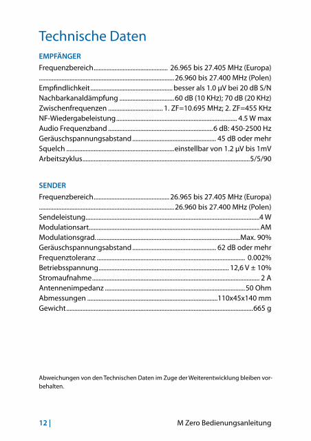
Technische DatenEMPFÄNGER
Frequenzbereich .............................................. 26.965 bis 27.405 MHz (Europa)....................................................................................26.960 bis 27.400 MHz (Polen)Empfindlichkeit ................................................... besser als 1.0 µV bei 20 dB S/NNachbarkanaldämpfung ..................................60 dB (10 KHz); 70 dB (20 KHz)Zwischenfrequenzen .................................. 1. ZF=10.695 MHz; 2. ZF=455 KHzNF-Wiedergabeleistung ........................................................................... 4.5 W maxAudio Frequenzband .................................................................6 dB: 450-2500 HzGeräuschspannungsabstand .................................................... 45 dB oder mehrSquelch ...................................................................einstellbar von 1.2 µV bis 1mVArbeitszyklus ........................................................................................................5/5/90
SENDER
Frequenzbereich ............................................... 26.965 bis 27.405 MHz (Europa)....................................................................................26.960 bis 27.400 MHz (Polen)Sendeleistung ............................................................................................................4 WModulationsart.......................................................................................................... AMModulationsgrad. .........................................................................................Max. 90%Geräuschspannungsabstand .................................................... 62 dB oder mehrFrequenztoleranz ............................................................................................ 0.002%Betriebsspannung ................................................................................. 12,6 V ± 10%Stromaufnahme ........................................................................................................ 2 AAntennenimpedanz .......................................................................................50 OhmAbmessungen .................................................................................110x45x140 mmGewicht ....................................................................................................................665 g
Abweichungen von den Technischen Daten im Zuge der Weiterentwicklung bleiben vor-behalten.

M Zero Manual de Instrucciones | 1
FUNCIONES PRINCIPALES ..................................2
MANDOS Y FUNCIONES .....................................3
INSTALACIÓN .........................................................5
CAMBIO DEL FUSIBLE .......................................................................................... 6
CONEXIÓN DEL MICRÓFONO ........................................................................... 6
MONTAJE DE LA ANTENA .................................................................................. 7
Posiciones comunes de montaje de la antena .......................................... 8
ANTENA PARA ESTACIÓN BASE ....................................................................... 8
USO DEL TRANSCEPTOR ....................................9
AJUSTE BANDA Po/St ........................................................................................10
EXPLORACIÓN RÁPIDA .....................................................................................10
SONIDO TECLADO ..............................................................................................10
MEMORIZACIÓN CANAL DE EMERGENCIA ................................................11
ALTAVOZ SUPLETORIO EXT .............................................................................11
FUNCIÓN PA .........................................................................................................11
CONSEJOS PARA USAR SU CB ....................... 12
SERVICIO Y MANTENIMIENTO ....................... 13
CARACTERÍSTICAS TÉCNICAS ........................ 14
2 | M Zero Manual de Instrucciones
FUNCIONES PRINCIPALES• Display para la visualización del canal en uso;
• Control RF Gain: permite regular la ganancia del receptor. Rotando en sentido horario se incrementa la sensibilidad del receptor; en sentido anti-horario, se reduce la sensibilidad (esto es útil cuando se reciban señales fuertes);
• SQUELCH: permite eliminar el ruido de fondo presente en recepción: Para la máxima sensibilidad del receptor deberá regular este mando a una posición inmediatamente superior al nivel donde desaparece el ruido de fondo;
• Conmutador CH/EMG: permite conmutar inmediatamente al canal de emergencia (el canal de emergencia puede fijarlo el usuario);
M Zero Manual de Instrucciones | 3
13,8V DC
PA EXTANT
9 8 7 6
1213
5
4321
10 11
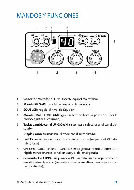
MANDOS Y FUNCIONES
1. Conector micrófono 4 PIN: Inserte aquí el micrófono;
2. Mando RF GAIN: regula la ganancia del receptor;
3. SQUELCH: regula el nivel de Squelch;
4. Mando ON/OFF-VOLUME: gire en sentido horario para encender la radio y ajustar el volumen;
5. Teclas cambio canal UP/DOWN: sirven para seleccionar el canal de-seado;
6. Display canales: muestra el nº de canal sintonizado;
7. Led TX: se enciende cuando la radio transmite (se pulsa el PTT del micrófono);
8. CH-EMG: Canal en uso / canal de emergencia. Permite conmutar rápidamente entre el canal en uso y el de emergencia;
9. Conmutador CB/PA: en posición PA permite usar el equipo como amplificador de audio (necesita conectar un altavoz en la toma cor-respondiente);
4 | M Zero Manual de Instrucciones
13,8V DC
PA EXTANT
9 8 7 6
1213
5
4321
10 11
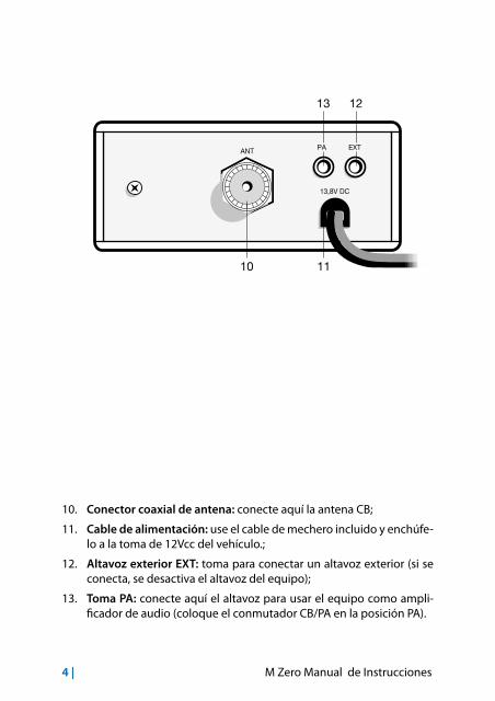
10. Conector coaxial de antena: conecte aquí la antena CB;
11. Cable de alimentación: use el cable de mechero incluido y enchúfe-lo a la toma de 12Vcc del vehículo.;
12. Altavoz exterior EXT: toma para conectar un altavoz exterior (si se conecta, se desactiva el altavoz del equipo);
13. Toma PA: conecte aquí el altavoz para usar el equipo como ampli-ficador de audio (coloque el conmutador CB/PA en la posición PA).
M Zero Manual de Instrucciones | 5
INSTALACIÓN
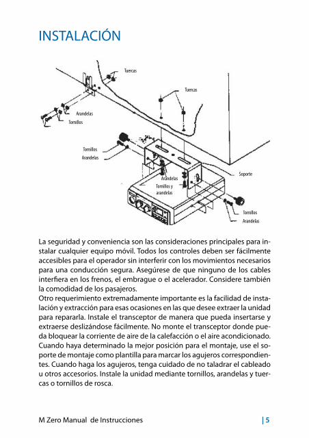
La seguridad y conveniencia son las consideraciones principales para in-stalar cualquier equipo móvil. Todos los controles deben ser fácilmente accesibles para el operador sin interferir con los movimientos necesarios para una conducción segura. Asegúrese de que ninguno de los cables interfiera en los frenos, el embrague o el acelerador. Considere también la comodidad de los pasajeros.Otro requerimiento extremadamente importante es la facilidad de insta-lación y extracción para esas ocasiones en las que desee extraer la unidad para repararla. Instale el transceptor de manera que pueda insertarse y extraerse deslizándose fácilmente. No monte el transceptor donde pue-da bloquear la corriente de aire de la calefacción o el aire acondicionado.Cuando haya determinado la mejor posición para el montaje, use el so-porte de montaje como plantilla para marcar los agujeros correspondien-tes. Cuando haga los agujeros, tenga cuidado de no taladrar el cableado u otros accesorios. Instale la unidad mediante tornillos, arandelas y tuer-cas o tornillos de rosca.
Arandelas
Arandelas
Arandelas
Arandelas
Tornillos
Tornillos
Tornillos
Soporte
Tuercas
Tuercas
Tornillos y arandelas

6 | M Zero Manual de Instrucciones
13,8V DC
PA EXTANT
Para instalaciones en vehículo, la tensión de 12,6Vcc ± 10% se puede obtener también del contacto auxiliar del interruptor de encendido. Introduzca el cable con la conexión para encendedor en la toma de éste del vehículo.Antes de usar el equipo, deberá instalar y conectar la antena. El cable de la antena deberá conectarlo a la toma de antena. Si está usando un altavoz externo, conéctelo a la toma EXT-SPKR.
CAMBIO DEL FUSIBLESustituya el fusible del cable de alimentación con uno similar de 2 ampe-rios (hay un fusible de recambio en dotación).
CONEXIÓN DEL MICRÓFONOLa toma del micrófono está situada en la parte frontal del equipo. Asegúrese siempre de que el conector esté bien conectado a dicha toma.
M Zero Manual de Instrucciones | 7
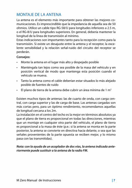
MONTAJE DE LA ANTENALa antena es el elemento más importante para obtener las mejores co-municaciones. Es imprescindible que la impedancia de aquella sea de 50 ohmios. Utilice un cable tipo RG-58/U para longitudes inferiores a 2.5 m, o el RG-8/U para longitudes superiores. En general, debería mantener la longitud de la línea de transmisión al mínimo.Estas indicaciones son importantes tanto para la recepción como para la transmisión. Si existe un desajuste entre la antena y el receptor, la exce-lente sensibilidad y la relación señal-ruido del circuito del receptor se perderán.
Consejos:
• Monte la antena en el lugar más alto y despejado posible
• Manténgala tan lejos como sea posible de la masa del vehículo y en posición vertical de modo que mantenga esta posición cuando el vehículo se mueva.
• Tanto la antena como el cable deberían estar situados lo más alejado posible de fuentes de ruido
• El plano de tierra de la antena debe cubrir un área mínima de 1 m2
Existen muchos tipos de antenas: las de cuarto de onda, con carga cen-tral, con carga superior y las de carga de base. Las antenas cargadas son más cortas pero, para un óptimo rendimiento, recomendamos aquellas de longitud cercana a los 2m.La instalación en el centro del techo es la mejor en términos absolutos ya que el plano de tierra es proporcional en todas las direcciones, mientras que un montaje en cualquier otra parte del vehículo, el plano de tierra es proporcional a la masa de éste (p.e.: si la antena se monta en la parte posterior, la antena se convierte en directiva hacia delante, o sea que las señales provenientes de la parte opuesta se reciben mejor, y lo mismo pasa con las transmitidas).
Nota: con la ayuda de un acoplador de dos vías, la antena indicada ante-riormente puede sustituir a la antena de la radio FM.
8 | M Zero Manual de Instrucciones
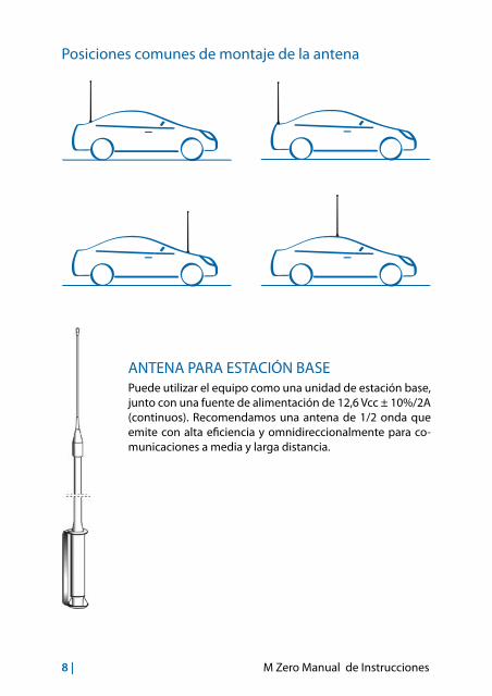
Posiciones comunes de montaje de la antena
ANTENA PARA ESTACIÓN BASEPuede utilizar el equipo como una unidad de estación base, junto con una fuente de alimentación de 12,6 Vcc ± 10%/2A (continuos). Recomendamos una antena de 1/2 onda que emite con alta eficiencia y omnidireccionalmente para co-municaciones a media y larga distancia.
M Zero Manual de Instrucciones | 9
USO DEL TRANSCEPTORPara recibir
1. Asegúrese de que el cable de conexión para el encendedor esté cor-rectamente conectado en una toma de 12V.
2. Asegúrese de que la antena y el micrófono están correctamente co-nectados.
3. Fije el interruptor de emergencia en la posición CH .
4. Fije el control del silenciador (SQUELCH) en la posición máxima en sentido inverso al de las agujas del reloj.
5. Mueva el control RF-GAIN totalmente en sentido horario.
6. Encienda El equipo girando El control del volumen en la dirección de las agujas del reloj.
7. Busque el canal deseado mediante los pulsadores CHANNEL.
8. Ajuste el volumen para un nivel de escucha adecuado.
9. Ajuste el silenciador (SQUELCH) para detener el ruido de fondo cuando no se recibe ninguna señal. Para hacerlo, fije el Selector de Canales en un canal donde no hay señales o espere hasta que no haya señales en su canal.
Haga girar el control del silenciador (SQUELCH) en la dirección de las agujas del reloj hasta que el ruido de fondo desaparezca. Entonces, cuan-do haya una señal, la oirá, pero no le molestará el ruido entre las señales en el canal. Cuando se ha fijado correctamente, el silenciador mantiene el receptor “muerto” hasta que aparece una señal en ese canal. Sin embar-go, no fije el silenciador demasiado alto, o las señales débiles no podrán abrir el circuito del silenciador. El circuito del silenciador en su transcep-tor es de un diseño avanzado. Utiliza un amplificador IC operacional para llevar a cabo la acción de histéresis. El resultado es que cuando fija el silenciador para un nivel de señal preciso, si la fuerza del nivel de dicha señal crece o decrece, el circuito del silenciador seguirá este cambio. Con circuitos de silenciador convencionales, a menudo una señal que cam-bia en fuerza queda “cortada” por el circuito del silenciador y se pierde una parte del mensaje. Con este silenciador puede escuchar el mensaje completo.

10 | M Zero Manual de Instrucciones
Para transmitir1. Seleccione el canal deseado.
2. Pulse el botón PTT (pulsar-para-hablar) del micrófono y mantenga éste a una distancia de unos 5-8 cm de su boca y hable frente a él en un tono de voz normal.
3. Para recibir, libere el botón PTT.Nota: Tenga en cuenta que gritar frente al micrófono no incrementará su potencia o señal. Un circuito interno fija automáticamente la señal del micrófono a la modulación máxima, por lo que no tiene ningún sentido hablar en voz muy alta. De hecho, si grita, su mensaje puede distorsio-narse.
AJUSTE BANDA Po/St1. Mantenga pulsadas las teclas UP/DOWN mientras enciende el equi-
po;
2. Pulse UP o DOWN para seleccionar la banda deseada: Po = Polonia (40CH AM – 26.960/27.400) – St = Europa (40CH AM- 26.965/27.405)
3. Pulse PTT para validar la selección.
EXPLORACIÓN RÁPIDAPara efectuar un exploración rápida de los canales, mantenga pulsada durante aproximadamente 6 segundos la tecla UP o DOWN.
SONIDO TECLADOCuando esta función está activa, la radio emite un beep cada vez que se pulsa una tecla.Para activar/desactivar el beep:1. Mantenga pulsada la tecla UP y encienda la radio;
2. Pulse la tecla UP o DOWN para activar o desactivar el beep;
3. El display mostrará “ON” cuando el beep esté activo u “OF” cuando esté desactivado.
M Zero Manual de Instrucciones | 11
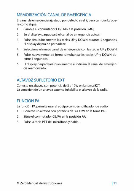
MEMORIZACIÓN CANAL DE EMERGENCIAEl canal de emergencia ajustado por defecto es el 9; para cambiarlo, ope-re como sigue:1. Cambie el conmutador CH/EMG a la posición EMG;
2. En el display parpadeará el canal de emergencia actual;
3. Pulse simultáneamente las teclas UP y DOWN durante 5 segundos. El display dejará de parpadear;
4. Seleccione el nuevo canal de emergencia con las teclas UP y DOWN;
5. Pulse nuevamente de forma simultanea las teclas UP y DOWN du-rante 5 segundos;
6. El display parpadeará nuevamente e indicará el canal de emergen-cia memorizado.
ALTAVOZ SUPLETORIO EXTConecte un altavoz con potencia de 3 a 10W en la toma EXT.La conexión de un altavoz externo inhabilita el altavoz de la radio.
FUNCIÓN PALa función PA permite usar el equipo como amplificador de audio.1. Conecte un altavoz con potencia de 3 a 10W en la toma PA;
2. Sitúe el conmutador CB/PA en la posición PA;
3. Pulse la tecla PTT del micrófono y hable.
12 | M Zero Manual de Instrucciones
CONSEJOS PARA USAR SU CB• Espere un momento de pausa en la transmisión antes de solicitar su
entrada.
• Si no recibe ninguna respuesta después de una segunda llamada a otra estación, no insista más y deje que otros puedan utilizar el ca-nal. Espere unos minutos, solicite de nuevo su entrada e inténtelo de nuevo.
• Nunca mantenga pulsada la tecla de transmisión si no desea hablar. La portadora emitida impedirá que otros puedan comunicarse libre-mente.
• Ayude a los usuarios que requieran información sobre direcciones, condiciones de las carreteras u otros datos.
• Sea cortés. Trate a los demás como desearía que le tratasen a usted.
M Zero Manual de Instrucciones | 13
SERVICIO Y MANTENIMIENTOSu transceptor ha sido fabricado siguiendo los estándares de control de calidad de fábrica. Sin embargo, debe tratarse con el cuidado que todos los equipos electrónicos requieren. Evite exponer la unidad a golpes, su-ciedad o humedad.
En caso de problemas, compruebe lo siguiente:
1. Si el problema se produce al recibir:
• Compruebe si el volumen está apagado.• Asegúrese de que el silenciador (SQUELCH) está ajustado adecua-
damente. Quizás está demasiado silenciado.• Compruebe si la unidad está sintonizada en un canal activo.• Asegúrese de que el conector del micrófono está firmemente in-
troducido en su zócalo.• Compruebe si la antena y el cable están correctamente conecta-
dos.2. Si el problema se produce al transmitir:
• Compruebe si la línea de transmisión está correctamente conecta-da al conector de antena.
• Compruebe si la instalación de la antena es la correcta.• Asegúrese de que el PTT no está pulsado.• Asegúrese de que el conector del micrófono está firmemente in-
troducido en su zócalo.3. Si el transceptor es inoperativo.
• Compruebe el cable de corriente y el fusible incorporado. Si el fu-sible está fundido, reemplácelo con un fusible idéntico de 2 ampe-rios.
Si todas estas comprobaciones no solucionan su problema, NO intente efectuar reparaciones o ajustes por su cuenta. Un técnico cualificado deberá reparar la unidad. Siempre que le sea posible, lleve el equipo al establecimiento donde lo adquirió o remítalo directamente a la dirección que figura en el certificado de garantía.
ADVERTENCIA: No abra el transceptor para efectuar ajustes internos. Cualquier ajuste interno sólo puede ser efectuado por personal debida-mente cualificado.
14 | M Zero Manual de Instrucciones
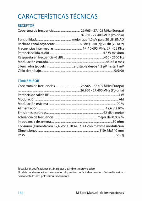
CARACTERÍSTICAS TÉCNICASRECEPTOR
Cobertura de frecuencias .................................. 26.965 - 27.405 MHz (Europa).....................................................................................26.960 - 27.400 MHz (Polonia)Sensibilidad .................................................mejor que 1,0 µV para 20 dB SINADRechazo canal adyacente .................................60 dB (10 KHz); 70 dB (20 KHz)Frecuencias intermedias .......................................1ª=10.695 MHz; 2ª=455 KHzPotencia salida audio .........................................................................4.5 W máximoRespuesta en frecuencia (6 dB) .......................................................450 - 2500 HzModulación cruzada ...............................................................................45 dB o másSilenciador (squelch) ..................................ajustable desde 1.2 µV hasta 1 mVCiclo de trabajo ...................................................................................................5/5/90
TRANSMISOR
Cobertura de frecuencias .................................. 26.965 - 27.405 MHz (Europa).....................................................................................26.960 - 27.400 MHz (Polonia)Potencia de salida RF ..............................................................................................4 WModulación................................................................................................................. AMModulación máxima ............................................................................................ 90 %Alimentación ............................................................................................ 12,6 V ±10%Emisiones espúreas ............................................................................62 dB o mejorTolerancia de frecuencia ...........................................................mejor del 0.002 %Impedancia de antena ....................................................................................50 ohmConsumo (alimentación 12,6 Vcc ± 10%) .. 2.0 A con máxima modulaciónDimensiones ....................................................................................110x45x140 mmPeso ...........................................................................................................................665 g
Todas las especificaciones están sujetas a cambio sin previo aviso. El cable de alimentación incorpora un dispositivo de fácil desconexión. Dicho dispositivo desconecta los dos polos simultáneamente.

M Zero Guide de utilisation | 1
FONCTIONS PRINCIPAUX ...................................2
CONTROLES ET FONCTIONS .............................3
INSTALLATION ........................................................5
SUBSTITUTION DU FUSIBLE .............................................................................. 6
CONNEXION DU MICROPHONE ....................................................................... 6
MONTAGE DE L’ANTENNE .................................................................................. 7
POSITIONS COMMUNES DE MONTAGE DE L’ANTENNE ....................... 8
ANTENNE BASE...................................................................................................... 8
USAGE DE L’EMETTEUR-RECEPTEUR ..............9
REGLAGE BANDE Po/St .....................................................................................10
GLISSEMENT RAPIDE DES CANAUX .............................................................10
BEEP TOUCHES ...................................................................................................10
MEMORISATION DU CANAL D’URGENCE ..................................................10
FONCTION PA.......................................................................................................11
CARACTERISTIQUES TECHNIQUES............... 12
2 | M Zero Guide de utilisation
FONCTIONS PRINCIPAUX• Afficheur pour la visualisation du canal actif;
• Sélecteur RF GAIN: permet le réglage de la sensibilité du récepteur. Tournez le sélecteur in sens horaire pour augmenter la sensibilité; à fond gauche vous obtiendrez une sensibilité minimale (lors de la réception des forts signaux).
• Sélecteur SQUELCH: pour éliminer le bruit de fond en réception. Stopper la rotation à l’endroit exact ou le bruit audible dans le haut-parleur disparait.
• CH/EMG: permet la commutation immédiate sur le canal d’urgence (peut être réglé par l’utilisateur).
M Zero Guide de utilisation | 3
13,8V DC
PA EXTANT
9 8 7 6
1213
5
4321
10 11
CONTROLES ET FONCTIONS
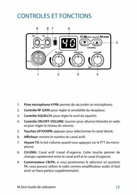
1. Prise microphone 4 PIN: permet de raccorder un microphone;
2. Contrôle RF GAIN: pour régler la sensibilité du récepteur;
3. Contrôle SQUELCH: pour régler le seuil du squelch;
4. Contrôle ON/OFF-VOLUME: tourner pour allumer/éteindre la radio et pour régler le niveau du volume;
5. Touches UP/DOWN: appuyer pour sélectionner le canal désiré;
6. Afficheur: montre le numéro du canal actif;
7. Voyant TX: le led s’allume quand vous appuyez sur le PTT du micro-phone;
8. CH-EMG: Canal actif /canal d’urgence. Cette touche permet de changer rapidement entre le canal actif et le canal d’urgence;
9. Commutateur CB/PA: si vous positionnez le sélecteur en position PA, vous pouvez utiliser la radio comme amplificateur audio (il faut avoir un haut-parleur supplémentaire).
4 | M Zero Guide de utilisation
13,8V DC
PA EXTANT
9 8 7 6
1213
5
4321
10 11
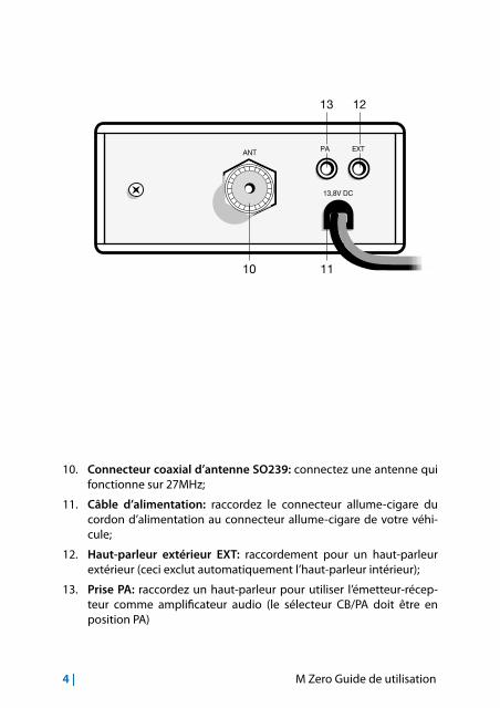
10. Connecteur coaxial d’antenne SO239: connectez une antenne qui fonctionne sur 27MHz;
11. Câble d’alimentation: raccordez le connecteur allume-cigare du cordon d’alimentation au connecteur allume-cigare de votre véhi-cule;
12. Haut-parleur extérieur EXT: raccordement pour un haut-parleur extérieur (ceci exclut automatiquement l’haut-parleur intérieur);
13. Prise PA: raccordez un haut-parleur pour utiliser l’émetteur-récep-teur comme amplificateur audio (le sélecteur CB/PA doit être en position PA)
M Zero Guide de utilisation | 5
INSTALLATION
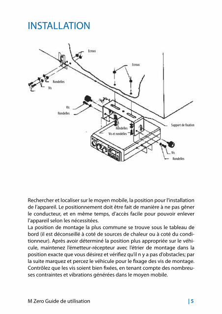
Rechercher et localiser sur le moyen mobile, la position pour l’installation de l’appareil. Le positionnement doit être fait de manière à ne pas gêner le conducteur, et en même temps, d’accès facile pour pouvoir enlever l’appareil selon les nécessitées.La position de montage la plus commune se trouve sous le tableau de bord (il est déconseillé à coté de sources de chaleur ou à coté du condi-tionneur). Après avoir déterminé la position plus appropriée sur le véhi-cule, maintenez l’émetteur-récepteur avec l’étrier de montage dans la position exacte que vous désirez et vérifiez qu’il n y a pas d’obstacles; par la suite marquez et percez le véhicule pour le fixage des vis de montage. Contrôlez que les vis soient bien fixées, en tenant compte des nombreu-ses contraintes et vibrations générées dans le moyen mobile.
Rondelles
Rondelles
Rondelles
Rondelles
Vis
Vis
Vis
Support de fixation
Ecrous
Ecrous
Vis et rondelles

6 | M Zero Guide de utilisation
13,8V DC
PA EXTANT
Raccordez le connecteur allume-cigare du cordon d’alimentation au con-necteur allume-cigare de votre véhicule.Pour l’installation dans l’automobile, la tension à 12,6 Vcc ± 10% est généralement prélevable par le contact auxiliaire de l’interrupteur d’al-lumage. Avant de commencer, installez et connectez l’antenne introduisant le connecteur dans la prise appropriée derrière l’appareil. Pour l’emploi d’un haut-parleur extérieur, utilisez la prise EXT-SPKR.
SUBSTITUTION DU FUSIBLESubstituez le fusible du câble d’alimentation avec un similaire à 2 A (Un fusible de rechange est fourni).
CONNEXION DU MICROPHONELa prise du microphone est placée sur le devant de l’appareil. Vous devez toujours vérifier que le connecteur soit bien connecté à la prise.

M Zero Guide de utilisation | 7
MONTAGE DE L’ANTENNEL’antenne est l’élément le plus important pour obtenir les meilleurs résul-tats. Il est indispensable que l’antenne ait une impédance de 50 Ohm. Selon son installation, le rendement change considérablement. Utilisez un câble coaxial avec impédance 50 Ohm. Nous conseillons les câbles RG 58U pour une longueur sous les 2,5 mètres ou RG 8 pour les longueurs supérieures. Le câble coaxial doit être monté très soigneusement: évitez courbes et pliages. De plus rappelez-vous qu’un câble plus court au-gmente la sensibilité de l’appareil, c’est la même chose avec une mauvai-se connexion entre l’appareil et l’antenne.
Conseils:
• Monter l’antenne à l’endroit le plus dégagé et le plus haut de l’auto-mobile.
• L’antenne doit être installée en position verticale, et elle doit le rester même quand le véhicule est en marche.
• Monter l’antenne et le câble le plus loin possible des sources de bruit.
• La masse de l’antenne doit couvrir une surface de 1m2.
Dans le commerce il y a des types d’antenne différents: avec stylo à 1/4 d’onde; alimentées au centre; avec la charge à la base; avec la charge en haute. Les antennes chargées sont plus courtes, mais pour un bon ren-dement nous conseillons les antennes d’environ 2 mètres de longueur.L’installation au centre du toit est la meilleure en sens absolu parce que le ground ou radial de terre est proportionnel dans toutes les directions, alors que sur un côté ou dans n’importe quelle autre partie du véhicule, elle devient proportionnelle à la masse d’elle-même (exemple: si l’anten-ne est installée dans la partie postérieure, elle devient directive en avant, c’est-à-dire que les signaux provenant de la part opposée sont mieux reçus, c’est la même chose pour les signal transmis).
8 | M Zero Guide de utilisation
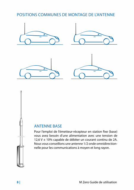
POSITIONS COMMUNES DE MONTAGE DE L’ANTENNE
ANTENNE BASEPour l’emploi de l’émetteur-récepteur en station fixe (base) vous avez besoin d’une alimentation avec une tension de 12,6 V ± 10% capable de débiter un courant continu de 2A. Nous vous conseillons une antenne 1/2 onde omnidirection-nelle pour les communications à moyen et long rayon.
M Zero Guide de utilisation | 9
USAGE DE L’EMETTEUR-RECEPTEURRéception:
1. Assurez-vous que le connecteur allume-cigare est bien connecté à une prise d’alimentation 12V.
2. Vérifiez que l’antenne et le microphone sont bien connectés.
3. Placez le commutateur d’urgence sur la position CH.
4. Tournez le bouton squelch dans la position maximale contraire à celle des aiguilles d’une montre.
5. Allumez l’appareil avec le bouton VOLUME.
6. Tournez le sélecteur RF-GAIN totalement dans le sens horaire.
7. Recherchez le canal que vous désirez parmi les touches CHANNEL.
8. Réglez le volume comme vous le désirez.
9. Réglez le squelch. Cette commande est utilisée pour éliminer le bru-it de fond du récepteur en absence de signal d’entrée. Pour la sensi-bilité maximale du récepteur il est préférable que la commande soit réglée seulement au niveau précis où le bruit de fond du récepteur ou le bruit ambiant est éliminé. Tournez complètement dans le sens contraire à celui des aiguilles d’une montre et après lentement dans le sens des aiguilles d’une montre jusqu’à ce que le bruit ait disparu. N’importe quel signal pourra être reçu, il devra être légèrement plus intense de la moyenne du bruit reçu. Une autre rotation dans le sens des aiguilles d’une montre augmentera le niveau de seuil que le si-gnal devra dépasser pour être ouit. Si le squelch est positionné dans la position maximale dans le sens des aiguilles d’une montre, vous entendrez seulement des signaux très intenses.
Emission:
1. Sélectionnez le canal désiré.
2. Pressez le bouton d’émission sur le microphone, parlez en plaçant le micro à environ 5 à 8 cm de vos lèvres.
3. Pour recevoir, relâchez le bouton d’émission.N.B.: crier dans le microphone n’augmente pas la charge de l’émission, puisqu’un circuit intérieur commute automatiquement la modulation maximale. Nous conseillons d’utiliser un ton de voix normal.

10 | M Zero Guide de utilisation
REGLAGE BANDE Po/St1. Allumez M ZERO en maintenant appuyé les touches UP/DOWN;
2. Appuyez UP ou DOWN pour sélectionner la bande désirée: Po = Pologne (40 Ch AM - 26.960/27.400) - St =Europe (40 CH AM - 26.965/27.405)
3. Appuyez PTT pour sortir de la sélection.
GLISSEMENT RAPIDE DES CANAUXPour glisser rapidement les canaux, maintenez appuyé sur les touches UP ou DOWN pour 6 secondes.
BEEP TOUCHES Quand cette fonction est active, vous entendrez un beep à chaque ap-puye d’une touche. Pour activer/désactiver le beep:
1. Allumez la radio en maintenant appuyé la touche UP;
2. Relâchez-la et appuyez les touches UP ou DOWN pour activer/désactiver le beep;
3. L’afficheur montrera ‘ON’ si le beep est active ou ‘OF’ quand le beep est désactive.
MEMORISATION DU CANAL D’URGENCE Le canal d’urgence par default est 19; pour le changer:
1. Positionnez le sélecteur CH/EMG en position EMG;
2. Sur l’afficheur clignotera en vert le canal d’urgence actuel;
3. Appuyez les touches UP et DOWN dans le même temps pour 5 se-condes. L’afficheur cesse de clignoter;
4. Sélectionnez un autre canal d’urgence avec UP / DOWN;
5. Appuyez de nouveau les touches UP et DOWN pour 5 secondes en-viron;
6. L’afficheur clignotera de nouveau et indiquera le nouvel canal mémorisé.
M Zero Guide de utilisation | 11
7. HAUT-PARLEUR SUPPLEMENTAIRE EXT Connectez à la prise EXT un haut-parleur avec une puissance de 3 à 10 Watt. La connexion à un haut-parleur extérieur exclut automatiquement l’intérieur.
FONCTION PALa fonction PA permet d’utiliser la radio comme amplificateur audio. 1. Connectez un haut-parleur avec une puissance de 3 à 10 Watt dans
une prise PA,
2. Positionner le selecteur CB/PA nella posizione PA,
3. premere il tasto PTT del microfono e parlare.
12 | M Zero Guide de utilisation
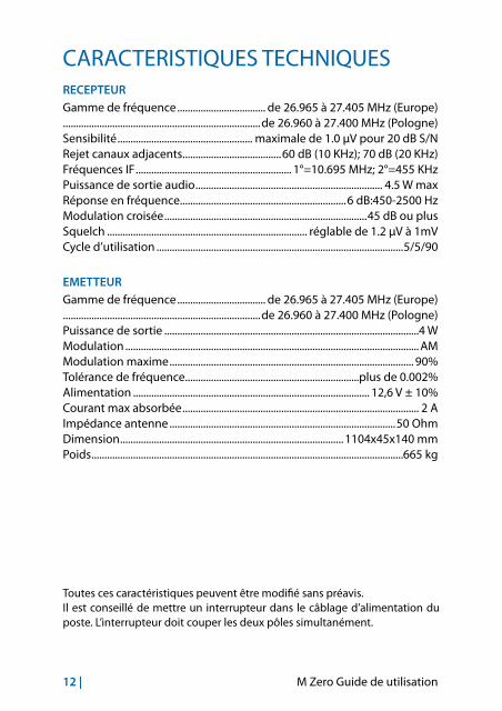
CARACTERISTIQUES TECHNIQUESRECEPTEURGamme de fréquence .................................. de 26.965 à 27.405 MHz (Europe)............................................................................de 26.960 à 27.400 MHz (Pologne)Sensibilité .................................................... maximale de 1.0 µV pour 20 dB S/NRejet canaux adjacents ......................................60 dB (10 KHz); 70 dB (20 KHz)Fréquences IF ............................................................ 1°=10.695 MHz; 2°=455 KHzPuissance de sortie audio ........................................................................ 4.5 W maxRéponse en fréquence................................................................6 dB:450-2500 HzModulation croisée ..............................................................................45 dB ou plusSquelch ............................................................................. réglable de 1.2 µV à 1mVCycle d’utilisation ...............................................................................................5/5/90
EMETTEURGamme de fréquence .................................. de 26.965 à 27.405 MHz (Europe)............................................................................de 26.960 à 27.400 MHz (Pologne)Puissance de sortie ..................................................................................................4 W Modulation ................................................................................................................. AMModulation maxime .............................................................................................. 90%Tolérance de fréquence ...................................................................plus de 0.002%Alimentation ........................................................................................... 12,6 V ± 10%Courant max absorbée ........................................................................................... 2 AImpédance antenne .......................................................................................50 OhmDimension ......................................................................................1104x45x140 mmPoids ........................................................................................................................665 kg
Toutes ces caractéristiques peuvent être modifié sans préavis. Il est conseillé de mettre un interrupteur dans le câblage d’alimentation du poste. L’interrupteur doit couper les deux pôles simultanément.

M Zero Instrukcja obsługi | 1
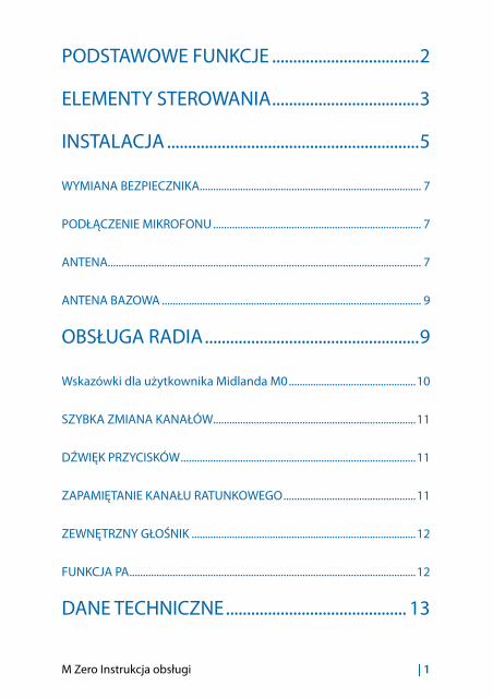
PODSTAWOWE FUNKCJE ...................................2
ELEMENTY STEROWANIA ...................................3
INSTALACJA ............................................................5
WYMIANA BEZPIECZNIKA.................................................................................. 7
PODŁĄCZENIE MIKROFONU ............................................................................. 7
ANTENA.................................................................................................................... 7
ANTENA BAZOWA ................................................................................................ 9
OBSŁUGA RADIA ...................................................9
Wskazówki dla użytkownika Midlanda M0 ...............................................10
SZYBKA ZMIANA KANAŁÓW...........................................................................11
DŹWIĘK PRZYCISKÓW .......................................................................................11
ZAPAMIĘTANIE KANAŁU RATUNKOWEGO .................................................11
ZEWNĘTRZNY GŁOŚNIK ...................................................................................12
FUNKCJA PA ..........................................................................................................12
DANE TECHNICZNE ........................................... 13

2 | M Zero Instrukcja obsługi
PODSTAWOWE FUNKCJE• Wyświetlanie aktualnie używanego kanału
• RF GAIN: Regulacja czułości odbiornika. Obracając pokrętło w prawo zwiększasz czułość radia, kręcąc w lewo – zmniejszasz ( pomocne przy silnych sygnałach lub wysokim poziomie szumów)
• SQUELCH: Blokada szumów. Prawidłowe ustawienie polega na powolnym przekręcaniu pokrętła z lewego skrajnego położenia zgodnie z ruchem wskazówek zegara do momentu aż szumy tła przestaną być słyszalne. Dalsze przekręcanie spowoduje że słabe sygnały od dalszych korespondentów nie będą odbierane.
• CH/EMG: Szybki dostęp do kanału zwyczajowo nazywanego ra-tunkowym. Można samemu wybrać kanał, który będzie dostępny za pomocą tego przełącznika

M Zero Instrukcja obsługi | 3
13,8V DC
PA EXTANT
9 8 7 6
1213
5
4321
10 11
ELEMENTY STEROWANIA
1. Gniazdo mikrofonu: Tu podłącz mikrofon.
2. Pokrętło RF GAIN: Reguluje czułość mikrofonu.
3. Pokrętło SQUELCH: Reguluje poziom blokady szumów.
4. ON/OFF-VOLUME: Włącza/wyłącza radiotelefon i reguluje siłę głosu.
5. GÓRA/DÓŁ: Przyciski zmiany kanału.
6. Wyświetlacz: Pokazuje numer aktualnie używanego kanału.
7. Dioda TX: Sygnalizuje nadawanie w trakcie trzymania wciśniętego przycisku PTT w mikrofonie.
8. CH-EMG: Przełącznik szybkiego dostępu do kanału ratunkowego i powrotu do aktualnie używanego.
9. CB/PA: ustawienie przełącznika w pozycji PA powoduje, że radio-telefon działa jak wzmacniacz akustyczny, jeżeli jest połączony z głośnikiem zewnętrznym PA; funkcje radiowe są nieaktywne. Położenie CB przywraca działanie radia

4 | M Zero Instrukcja obsługi
13,8V DC
PA EXTANT
9 8 7 6
1213
5
4321
10 11
10. Gniazdo anteny SO239: Tu podłącza się antenę pracującą w paśmie 27 MHz
11. Kabel zasilający: Przewód z wtykiem do gniazda zapalniczki o napięciu prądu stałego nie wyższym niż 13,8V.
12. Gniazdo zewnętrznego głośnika: Jeżeli słyszalność jest niezadowalająca można podłączyć zewnętrzny głośnik. Wsunięcie wtyku powoduje automatyczne odłączenie wbudowanego, wewnętrznego głośnika.
13. Gniazdo PA: umożliwia podłączenie zewnętrznego głośnika-tuby i wykorzystanie radiotelefonu jako wzmacniacza audio.
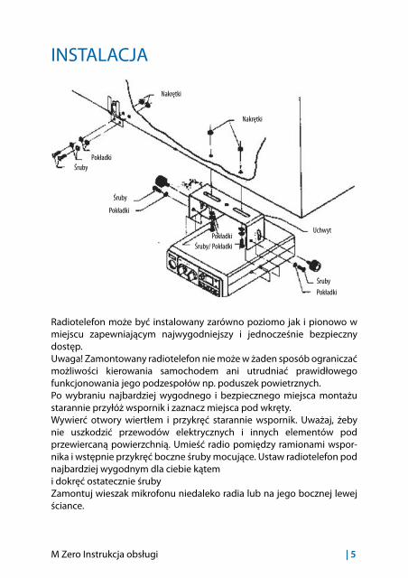
M Zero Instrukcja obsługi | 5
INSTALACJA
Radiotelefon może być instalowany zarówno poziomo jak i pionowo w miejscu zapewniającym najwygodniejszy i jednocześnie bezpieczny dostęp.Uwaga! Zamontowany radiotelefon nie może w żaden sposób ograniczać możliwości kierowania samochodem ani utrudniać prawidłowego funkcjonowania jego podzespołów np. poduszek powietrznych. Po wybraniu najbardziej wygodnego i bezpiecznego miejsca montażu starannie przyłóż wspornik i zaznacz miejsca pod wkręty.Wywierć otwory wiertłem i przykręć starannie wspornik. Uważaj, żeby nie uszkodzić przewodów elektrycznych i innych elementów pod przewiercaną powierzchnią. Umieść radio pomiędzy ramionami wspor-nika i wstępnie przykręć boczne śruby mocujące. Ustaw radiotelefon pod najbardziej wygodnym dla ciebie kątem i dokręć ostatecznie śrubyZamontuj wieszak mikrofonu niedaleko radia lub na jego bocznej lewej ściance.
Pokładki
Pokładki
Pokładki
Pokładki
Śruby
Śruby
Śruby
Uchwyt
Nakrętki
Nakrętki
Śruby/ Pokładki
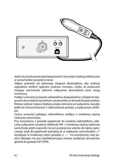
6 | M Zero Instrukcja obsługi
13,8V DC
PA EXTANT
Jeżeli nie jesteś pewny jaką biegunowość ma twoja instalacja elektryczna w samochodzie sprawdź to teraz.Odłącz przewód od ujemnego bieguna akumulatora, aby uniknąć zagrożenie krótkim spięciem podczas montażu, chyba, że producent twojego samochodu zabrania odłączania akumulatora poza stacją serwisową.Podłącz czerwony przewód radiotelefonu bezpośrednio z dodatnim bie-gunem akumulatora lub jednym z przewodów ze skrzynki bezpieczników. Możesz wybrać miejsce dopływu prądu odcinane po wyłączeniu stacyjki, jeżeli nie chcesz korzystać z radia podczas postoju z wyłączonym silniki-em.Czarny przewód zasilający radiotelefonu podłącz z metalową częścią nadwozia samochodu.Przy korzystaniu z gniazda zapalniczki do zasilania radiotelefonu, zale-camy połączenie obudowy Midlanda M0 z metalową częścią nadwozia samochodu jeżeli wspornik nie jest przykręcony właśnie do takiej części. Lutując wtyk do zapalniczki pamiętaj, że w większości samochodów ,,+” występuje w środkowej części gniazda, a ,,– ” na zewnętrznej. Gdy po-ziom dźwięku nie jest satysfakcjonujący możesz podłączyć zewnętrzny głośnik do gniazda EXT-SPKR.
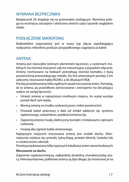
M Zero Instrukcja obsługi | 7
WYMIANA BEZPIECZNIKABezpiecznik 2A znajduje się na przewodzie zasilającym. Wymiana pole-ga na wciśnięciu zaczepów i obróceniu dwóch części oprawki względem siebie.
PODŁĄCZENIE MIKROFONURadiotelefon wyposażony jest w nowy typ złącza zapobiegający rozłączeniu mikrofonu podczas przypadkowego ciągnięcia za kabel.
ANTENAAntena jest niezwykle istotnym elementem łączności, a systemach mo-bilnych ma również znaczenie cały tor transmisyjny z pojazdem włącznie. Anteny montowane na łodziach potrzebują również kontaktu z dużą powierzchnią przewodzącego metalu. Do linii antenowych poniżej 2,5m zalecamy stosowanie kabla RG58U, a do dłuższych RG8.Poniżej przedstawiamy kilka ogólnych zasad mocowania anten. Pamiętaj, że to antena, jej prawidłowe zamocowanie i zestrojenie ma decydujący wpływ na zasięg łączności.
• Umieść antenę w najwyższym możliwym miejscu. Im wyżej wystaje ponad dach tym lepiej.
• Montuj antenę na środku wybranej przez ciebie powierzchni.
• Prowadź kabel antenowy z dala od źródeł zakłóceń np. systemu zapłonowego, wskaźników, prędkościomierza itp.
• Zapewnij antenie trwały, elektryczny kontakt z metalowymi częściami nadwozia.
• Uważaj aby zgnieść kabla antenowego.
Najlepszym miejscem mocowania anteny jest środek dachu. Alter-natywnie wybiera się rynienki, tylną klapę, przedni błotnik, lusterko lub w ostateczności zderzak.Poniżej przedstawiamy kilka typowych lokalizacji anten samochodowych
Mocowanie na dachuZapewnia najskuteczniejszą, najbardziej dookólną charakterystykę pra-cy. Pełnowymiarowe, półfalowe anteny są zbyt długie, by montować je na

8 | M Zero Instrukcja obsługi
dachu, więc większość anten samochodowych ma na dole cewkę, która skraca ją fizycznie i dopasowuje elektrycznie.
Mocowanie na przednim błotnikuAntena ma lekko kierunkową charakterystykę pracy z uprzywilejowanym kierunkiem tylnym przeciwnym do mocowania anteny. Ta lokalizacja oferuje łatwy dostęp do punktu montażu. Za pomocą splitera można adaptować anteną CB do obsługi zwykłego radioodbiornika samocho-dowego.
Mocowanie na tylnym błotniku lub bagażniku.Antena ma lekko kierunkową charakterystykę pracy z uprzywilejowanym kierunkiem przednim przeciwnym do mocowania anteny. W tej pozycji oprócz standardowej, skróconej anteny można spróbować założyć pełnowymiarową ćwierćfalową o długości ok. 2,5 m.
Mocowanie na zderzaku Ten rodzaj mocowania najbardziej zaburza dookólną charakterystykę pracy anteny, wyróżniając tył lub przód, ale pozwala na zamontowanie najdłuższych anten i nie wymaga dziurawienia nadwozia.
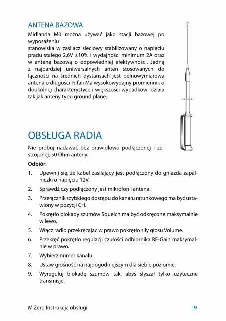
M Zero Instrukcja obsługi | 9
ANTENA BAZOWAMidlanda M0 można używać jako stacji bazowej po wyposażeniustanowiska w zasilacz sieciowy stabilizowany o napięciu prądu stałego 2,6V ±10% i wydajności minimum 2A oraz w antenę bazową o odpowiedniej efektywności. Jedną z najbardziej uniwersalnych anten stosowanych do łączności na średnich dystansach jest pełnowymiarowa antena o długości ½ fali Ma wysokowydajny promiennik o dookólnej charakterystyce i większości wypadków działa tak jak anteny typu ground plane.
OBSŁUGA RADIANie próbuj nadawać bez prawidłowo podłączonej i ze-strojonej, 50 Ohm anteny.
Odbiór:
1. Upewnij się, że kabel zasilający jest podłączony do gniazda zapal-niczki o napięciu 12V.
2. Sprawdź czy podłączony jest mikrofon i antena.
3. Przełącznik szybkiego dostępu do kanału ratunkowego ma być usta-wiony w pozycji CH.
4. Pokrętło blokady szumów Squelch ma być odkręcone maksymalnie w lewo.
5. Włącz radio przekręcając w prawo pokrętło siły głosu Volume.
6. Przekręć pokrętło regulacji czułości odbiornika RF-Gain maksymal-nie w prawo.
7. Wybierz numer kanału.
8. Ustaw głośność na najdogodniejszym dla siebie poziomie.
9. Wyreguluj blokadę szumów tak, abyś słyszał tylko użyteczne transmisje.

10 | M Zero Instrukcja obsługi
WSKAZÓWKI DLA UŻYTKOWNIKA MIDLANDA M0Kluczem do komfortowego odbioru jest właściwe ustawienie blokady szumów. Należy przeprowadzić ja na wolnym kanale lub poczekać na przerwę w rozmowach. Przekręcaj powoli w prawo pokrętło blokady szumów ze skrajnego, lewego położenia, do momentu aż szumu tła przestaną być słyszalne. Zostaw pokrętło dokładnie w tym położeniu. Gdybyś przekręcał dalej, tylko coraz to silniejsze sygnały mogłyby przebić się przez blokadę, więc straciłbyś możliwość odbioru bardziej odległych korespondentów. Układ użyty w Midlandzie M0 to zaawansowane rozwiązanie z histerezą podtrzymującą działanie Squelcha. W rezulta-cie słabe transmisje niestabilnym sygnałem, znajdujące się na granicy zasięgu nie będą przerywane przez błyskawiczne, krótkie interwencje blokady. Z drugiej strony pojedyncze, mocne impulsy szumu nie będą uruchamiały głośnika. Blokada w pewnym zakresie będzie podążać za fluktuacjami mocy sygnału i szumów poprawiając warunki odsłuchu.
Nadawanie:
1. Wybierz kanał.
2. Wciśnij i trzymaj cały czas wciśnięty przycisk nadawania PTT mówiąc normalnym głosem do mikrofonu trzymanego w odległości 5-7 cm od ust.
3. Chcąc odbierać zwolnij przycisk PTT. Pamiętaj, żeby mikrofon był prawidłowo podłączony do radia.
Pamiętaj: Krzyczenie do mikrofonu nie poprawi zasięgu łączności. Mikro-fon automatycznie koryguje sygnał do maksymalnego poziomu modu-lacji, więc głośne mówienie niczego nie poprawi.
M Zero Instrukcja obsługi | 11
WYBÓR STANDRDU1. Włącz radio trzymając wciśnięte jednocześnie oba przyciski zmiany
kanałów góra/dół.2. Przyciskami zmiany kanałów wybierz standard Po dla Polski (40
kanałów AM 26.960-27.400) lub St dla Europy ( 40 kanałów AM 26.965-27.405).
3. Wciśnij krótko przycisk nadawania PTT dla zatwierdzenia wyboru.
SZYBKA ZMIANA KANAŁÓWTrzymanie wciśniętego przycisku przez dłużej niż 6 sek. włącza szybką zmianę kanałów. Funkcja przydatna przy zmianie na kanał bardzo odległy od aktualnie używanego.
DŹWIĘK PRZYCISKÓWKrótki dźwięk potwierdzający użycie przycisków.Aktywacja tej funkcji przebiega następująco :L1. Włącz radio trzymając wciśnięty przycisk zmiany kanałów w górę
(UP)2. Przyciskami zmiany kanałów wybierz włącz/wyłącz.3. Wyświetlacz pokaże ON dla funkcji włączonej i OFF dla wyłączonej.
ZAPAMIĘTANIE KANAŁU RATUNKOWEGOKanał ratunkowy wybierany pod przełącznikiem szybkiego dostępu domyślnie jest kanałem 19. Jeżeli chciałbyś go zmienić postępuj zastosuj poniższą procedurę:1. Ustaw przełącznik szybkiego dostępu do kanału ratunkowego CH/
EMG w pozycję EMG.2. Na wyświetlaczu będzie migał numer kanału, który aktualnie jest
kanałem ratunkowym.3. Wciśnij i trzymaj wciśnięte jedocześnie przez5 sek. 2 przyciski do
zmiany kanałów.4. Przyciskami zmiany kanałów wybierz kanał, do którego chcesz mieć
szybki dostęp.5. Jeszcze raz wciśnij i trzymaj wciśnięte jedocześnie przez5 sek. 2
przyciski do zmiany kanałów.6. Wyświetlacz pokaże migający numer nowo wybranego kanału.
12 | M Zero Instrukcja obsługi
ZEWNĘTRZNY GŁOŚNIKDo gniazda na tylnym panelu można podłączyć zewnętrzny głośnik o mocy 3-10W. Podłączenie spowoduje automatyczne wyciszenie głośnika wewnętrznego, wbudowanego w radio.
FUNKCJA PAFunkcja PA zamienia radio we wzmacniacz akustyczny.1. Podłącz tubowy głośnik 3-10W do gniazda PA z tylu radia.
2. Przesuń w pozycję PA przełącznik CB/PA.
3. Naciśnij przycisk nadawania PTT i zacznij mówić
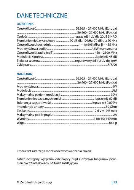
M Zero Instrukcja obsługi | 13
DANE TECHNICZNEODBIORNIKCzęstotliwość ........................................................ 26.965 – 27.400 MHz (Europa).......................................................................................26.960 - 27.400 MHz (Polska)Czułość ................................................................... lepsza niż 1µV dla 20dB SINADTłumienie międzykanałowe ....................60 dB dla 10 kHz; 70 dB dla 20 kHzCzęstotliwości pośrednie ........................................ I – 10.695 MHz; II – 455 kHzMoc wyjściowa audio.................................................................4,5W maksymalnaCzęstotliwości audio (6dB) ...........................................................450 – 2500 MHzModulacja skrośna ............................................................................lepiej niż 45 dBBlokada szumów..................................................regulowany od 1,2 µV do 1mVCykl pracy ..............................................................................................................5/5/90
NADAJNIKCzęstotliwość ........................................................ 26.965 – 27.400 MHz (Europa).......................................................................................26.960 - 27.400 MHz (Polska)Moc wyjściowa .......................................................................................................... 4WModulacja ................................................................................................................... AMMaksymalny poziom modulacji ........................................................................ 90%Tłumienie niepożądanych emisji ............................................... lepsze niż 62 dBTolerancja częstotliwości ...........................................................lepsza niż 0,002%Impedancja anteny .........................................................................................50 OhmZasilanie ............................................................................................12,6 V ±10% maxMaksymalny pobór prądu ...................................................................................... 2AWymiary .............................................................................................110x45x140 mmWaga .........................................................................................................................665 g
Producent zastrzega możliwość wprowadzenia zmian.
Łatwo dostępny wyłącznik odcinający prąd z obydwu biegunów powi-nien być zainstalowany na torze zasilającym.

• INFORMAZIONE AGLI UTENTI Ai sensi dell’art. 13 del decreto legislativo 25 luglio 2005, n.151 “Attuazione delle Direttive 2002/95/
CE, 2002/96/CE e 2003/108/CE, relative alla riduzione dell’uso di sostanze pericolose nelle apparec-chiature elettriche ed elettroniche, nonché allo smaltimento dei rifiuti”. Il simbolo del cassonetto bar-rato riportato sull’apparecchiatura indica che il prodotto alla fine della propria vita utile deve essere raccolto separatamente dagli altri rifiuti. L’utente dovrà, pertanto, conferire l’apparecchiatura giunta a fine vita agli idonei centri di raccolta differenziata dei rifiuti elettronici ed elettrotecnici, oppure ri-consegnarla al rivenditore al momento dell’acquisto di una nuova apparecchiatura di tipo equivalente, in ragione di uno a uno. L’adeguata raccolta differenziata per l’avvio successivo dell’apparecchiatura dismessa al riciclaggio, al trattamento e allo smaltimento ambientalmente compatibile contribuisce ad evitare possibili effetti negativi sull’ambiente e sulla salute e favorisce il riciclo dei materiali di cui è composta l’apparecchiatura. Lo smaltimento abusivo del prodotto da parte dell’utente comporta l’applicazione delle sanzioni amministrative di cui al dlgs. n.22/1997 (articolo 50 e seguenti del dlgs. n.22/1997).
• All articles displaying this symbol on the body, packaging or instruction manual of same, must not be thrown away into normal disposal bins but brought to specialised waste disposal centres. Here, the va-rious materials will be divided by characteristics and recycles, thus making an important contribution to environmental protection.
• Alle Artikel, die auf der Verpackung oder der Gebrauchanweisung dieses Symbol tragen, dürfen nicht in den normalen Mülltonnen entsorgt werden, sondern müssen an gesonderten Sammelstellen abge-geben werden. Dort werden die Materialien entsprechend ihrer Eigenschaften getrennt und, um einen Beitrag zum Umweltschutz zu liefern, wiederverwertet.
• Todos los artículos que exhiban este símbolo en el cuerpo del producto, en el embalaje o en el manual de instrucciones del mismo, no deben ser desechados junto a los residuos urbanos normales sino que deben ser depositados en los centros de recogida especializados. En estos centros, los materiales se di-vidirán en base a sus características y serán reciclados, para así poder contribuir de manera importante a la protección y conservación del medio ambiente.
• Tous les articles présentant ce symbole sur le corps, l’emballage ou le manuel d’utilisation de celui-ci ne doivent pas être jetés dans des poubelles normales mais être amenés dans des centres de traite-ment spécialisés. Là, les différents matériaux seront séparés par caractéristiques et recyclés, permet-tant ainsi de contribuer à la protection de l’environnement.
• Zużyte towary oznaczone tym znakiem mogą stanowić zagrożenie dla środowiska naturalnego, dlatego nie należy ich wyrzucać tylko oddać sprzedawcy, który przekaże je do przedsiębiorstwa zajmującego się utylizacja odpadów.
Italia - Restrizioni all’uso - In conformità al Piano Nazionale di ripartizione delle Frequenze, pubblicato sulla G.U. n. 169 -Supplemento Ordinario 146 - del 20 luglio 2002 - nota 49G -, per lo standard I in AM occorre utilizzare un sistema radiante che abbia il guadagno complessivo non superiore a -6 dB (es.: con antenna PC8 con cavo originale).
Italy - Restrictions on the use - According to the Italian Frequency Allocation Table, issued on the G.U. No. 169 - Sup-plement 146 - of 20th July 2002 - note 49G, the standard I in AM modulation needs a radiating system with a gain not higher than -6dB, such as, for example, with the antenna “PC8” with original cable.
Italie - Restrictions à l’usage - Conformément au Tableau National de répartition des bandes de fréquences publié sur la G.U. n. 169, Supplément 146 - du 20 Juillet 2002 – note 49G -, pour le standard I in modulation AM il faut utiliser un système radiante avec un gain pas supérieur à –6dB (par exemple, avec l’antenne PC8 avec câble original).
Italien - Nutzungshinweis - Entsprechend der Italienischen Frequenzverteilungstabelle, herausgegeben in G.U,. No. 169, Anhang 146 vom 20. Juli 2002, Note 49 G, darf bei Standard I in AM Modulation nur ein Antennensystem von nicht mehr als -6dB Gewinn benutzt werden, wie z.B. der Antennentyp “ PG 8 “ mit Originalkabel
Italia - Restricciones al uso - De acuerdo con el Piano Nazionale di Ripartizione delle Frequenze, publicado en la G.U. n° 169 - Supplemento Ordinario 146 - del 20 de julio de 2002 - nota 49G - , por el estándar I en la modalidad AM se deberá utilizar un sistema radiante que tenga una ganancia conjunta no superior a -6dB (es.: con antena “PC8” con cable original)
RTTE I / RSMCte International Srl dichiara che il prodotto è conforme ai requisiti essenziali e alle disposizioni della Direttiva 1999/5/CE. La Dichiarazione di conformità si può scaricare dal sito www.midlan-deurope.comUK / CY / MHereby Cte International Srl declares that this product is in compliance with the essential re-quirements and other relevant provisions of Di-rective 1999/5/EC. The declaration of conformity is available on the web site www.midlandeu-rope.com A / D / CH / FLHiermit erklärt Cte International Srl, dass das Produkt die grundlegenden Anforderungen und anderen relevanten Bestimmungen der Richtlinie 1999/5/EC erfüllt. Die Konformität-serklärung ist unter folgendem Link verfügbar: www.midlandeurope.comECTE International SRL. declara, bajo su responsa-bilidad, que este aparato cumple con lo dispue-sto en la Directiva 99/05/CE, del Parlamento Europeo y del Consejo de 9 de marzo de 1999, transpuesta a la legislación española mediante el Real Decreto 1890/2000, de 20 de noviembre. La Declaración de Conformidad está disponible en www.midlandeurope.comF / LUX / CHPar la présente Cte International Srl déclare que le modèle est conforme aux exigences essen-tielles et autres dispositions pertinentes de la directive 1999/5/EC. La déclaration de confor-mité est disponible sur le site internet www.midlandeurope.comPA CTE INTERNATIONAL declara que este aparelho cumpre com o disposto na Directiva 1999/5/CE do Parlamento Europeu e do Conselho de 9 de
Março de 1999, transposta para a legislação nacional pelo Decreto-Lei n.º 192/2000, de 18 de Agosto. A Declaração de Conformidade está disponível no sitio na Internet em www.midlandeurope.comGRΜε το παρών, η Cte International Srl δηλώνει οτι το όνομα του μοντέλου συμμορφώνεται ως προς τις βασικές απαιτήσεις και άλλες σχετικές διατάξεις του Κανονισμού 1999/5/EC. Η δήλωση συμμόρφωσης είναι διαθέσιμη στην ιστοσελίδα www.midlandeurope.com NLHierbij verklaard CTE International Srl dat dit model (-naam) voldoet aan de essentiële eisen en andere relevante bepalingen van richtlijn 1999/5/EG. De verklaring van conformiteit is beschikbaar op de website www.midlandeu-rope.comBECTE INTERNATIONAL Srl verklaart dat het product overeenstemt met de voorschriften en andere bepalingen van de richtlijn 1999/5/EC. De con-formiteitsverklaring is voorhanden op de website www.midlandeurope.comPL CTE International Srl deklaruje, że ten model jest zgodny z wymaganiami zasadniczymi i innymi istotnymi postanowieniami Dyrektywy 1999/5/EC. Deklaracja Zgodności jest dostepna na stro-nie www.midlandeurope.com ROCte International Srl declara ca acest model este in conformitate cu cerintele esentiale si alte prevederi ale Directivei 1999/5/EC. Declaratia de confomitate este disponibila si pe site-ul www.midlandeurope.com. BGС настоящото CTE international Srl декларира, че продукта е в съответствие с основните

изисквания и съответните модификации на Директива 1999/5/EC. Декларацията за съвместимост е налична на сайта: www.midlandeurope.comNCTE INTERNATIONAL Srl erklærer at produktet er i overensstemmelse med de viktigste kravene og andre relevante betingelser i Direktivet 1999/5/EF. Samsvarserklæringen finnes tilgjengelig på nettstedet www.midlandeurope.comDKHermed erklærer Cte International Srl , at dette apperat er i overensstemmelse med kravene og andre relevante bestemmelser i direktiv 1999/5 / EF. Overensstemmelseserklæringen findes på webstedet www.midlandeurope.comSECTE INTERNATIONAL Srl förkunnar att produkten överensstämmer med de väsentliga kraven och övriga bestämmelser i direktiv 1999/5/EG. Denna försäkran om överensstämmelse finns på webbplatsen www.midlandeurope.comFINCTE INTERNATIONAL Srl vakuuttaa, että tuote täyttää direktiivin 1999/5/EY asettamat olennaiset vaatimukset ja muut asiaa koskevat määräykset. Vaatimuksenmukaisuusvakuutus on saatavilla www.midlandeurope.com –verkkosivuilla.HRCte International Srl ovime izjavljuje da je ime ovog modela u suglasnosti sa bitnim zahtjevi-ma te ostalim relevantnim odredbama Propisa 1999/5/EC. Ova Izjava o suglasnosti je dostupna na web stranici www.midlandeurope.com.ESKäesolevaga kinnitab Cte International Srl selle mudeli vastavust direktiivi 1999/5/EC olulistele nõuetele ja teistele asjakohastele sätetele. Va-stavusdeklaratsioon on kättesaadav veebilehel www.midlandeurope.com
LTCTE International patvirtina, kad šis modelis atitinka visus esminius Direktyvos 1999/5/EC bei su ja susijusių dokumentų reikalavinus. Atitikties deklaracija yra pateikiama internetinėje svetainėje www.midlandeurope.comLVCTE INTERNATIONAL Srl deklarē, ka pro-dukts atbilst pamatprasībām un citiem ar to saistītajiem Direktīvas 1999/5/EK noteikumiem. Atbilstības deklarācija ir pieejama mājas lapā: www.midlandeurope.comSKTýmto Cte International Srl prehlasuje, že tento názov model je v zhode so základnými požiadavkami a ďalšími príslušnými ustanovenia-mi smernice 1999/5 / ES. Vyhlásenie o zhode je k dispozícii na webových stránkach www.midlan-deurope.comSLCte International Srl deklarira da je ta model skladen z bistvenimi zahtevami in drugimi rele-vantnimi določili EU direktive 1999/5/EC. Dekla-racija o skladnosti je na voljo na spletni strani www.midlandeurope.comCZCTE INTERNATIONAL SRL prohlašuje, že výrobek je v souladu s 1999/5 / ES. Prohlášení o shodě je k dispozici na webových stránkách www.midlan-deurope.comHMi, a CTE International Srl. saját felelősségre kije-lentjük, hogy ezen elnevezésű termék megfelel az 1999/5/EC alapvető követelményeinek és egyéb releváns előírásoknak. A megfelelőségi nyilatko-zat elérhető weboldalunkon a www.midlandeu-rope.com címen.

W W W. M I D L A N D E U R O P E . CO M |
Prodotto o importato da: CTE INTERNATIONAL s.r.l. Via. R.Sevardi 7- 42124 Reggio Emilia Italia www.midlandeurope.com L’uso di questo apparato può essere soggetto a restrizioni nazionali . Prima dell’uso leggere attentamente le istruzioni.
Produced or imported by: CTE INTERNATIONAL s.r.l. Via. R.Sevardi 7 42124 Mancasale Reggio Emilia Italy
Imported by: ALAN-NEVADA UK Unit 1 Fitzherbert Spur Farlington Portsmouth Hants. PO6 1TT - United Kingdom www.nevada.co.uk The use of this transceiver can be subject to national restrictions. Read the instructions carefully before installation and use.
Importado por: ALAN COMMUNICATIONS, SA C/Cobalt, 48 - 08940 Cornellà de Llobregat Barcelona España www.midland.es El uso de este equipo puede estar sujeto a la obtención de la correspondiente autoriza-ción administrativa. Lea atentamente las instrucciones antes de usar el equipo.
Vertrieb durch: ALAN ELECTRONICS GmbH Daimlerstraße 1K - D-63303 Dreieich Deutschland www.alan-electronics.de Die Benutzung dieses Funkgerätes ist von den landesspezifischen Bestimmungen abhän-gig. Vor Benutzung Bedienungsanleitung beachten. Bei Verwendung von Batterien beachten Sie bitte die Umweltbestimmungen.