Laurea Specialistica in Ingegneria...
52
Data:1/3/2003 Ingegneria dell'Automazione: Sistemi in Tempo Reale Luigi Palopoli Laurea Specialistica in Ingegneria dell'Automazione Sistemi in Tempo Reale Luigi Palopoli email: [email protected] Tel. 050 883444 FSM
Transcript of Laurea Specialistica in Ingegneria...

Data:1/3/2003 Ingegneria dell'Automazione: Sistemi in Tempo Reale Luigi Palopoli
Laurea Specialistica in Ingegneria dell'Automazione
Sistemi in Tempo Reale
Luigi Palopoliemail: [email protected] Tel. 050 883444
FSM

Data:1/3/2003 Ingegneria dell'Automazione: Sistemi in Tempo Reale Luigi Palopoli
Outline
● Finite State Machines (FSMs)
Data:1/3/2003 Ingegneria dell'Automazione: Sistemi in Tempo Reale Luigi Palopoli
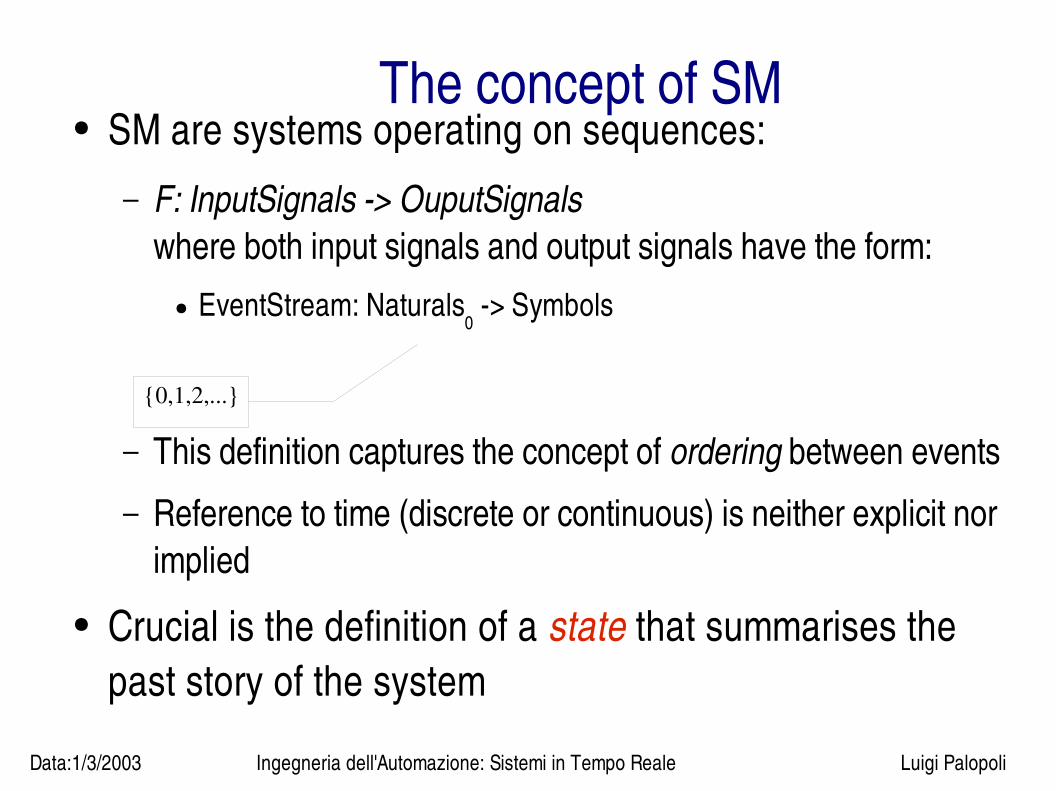
The concept of SM● SM are systems operating on sequences:
– F: InputSignals > OuputSignalswhere both input signals and output signals have the form:
● EventStream: Naturals0 > Symbols
– This definition captures the concept of ordering between events
– Reference to time (discrete or continuous) is neither explicit nor implied
● Crucial is the definition of a state that summarises the past story of the system
{0,1,2,...}
Data:1/3/2003 Ingegneria dell'Automazione: Sistemi in Tempo Reale Luigi Palopoli
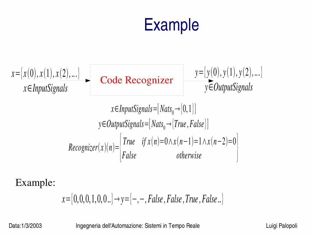
Example
Code Recognizerx={x 0 , x 1 , x 2 , .. .}
x∈InputSignalsy={y 0 , y 1 , y 2 , .. .}
y∈OutputSignals
x∈InputSignals=[Nats0{0,1}]y∈OutputSignals=[Nats0{True , False}]
Recognizerx n={True if x n=0∧x n−1=1∧x n−2=0False otherwise }
Example:
x={0, 0, 0,1, 0, 0 ..} y={−,−, False , False ,True , False ..}
Data:1/3/2003 Ingegneria dell'Automazione: Sistemi in Tempo Reale Luigi Palopoli
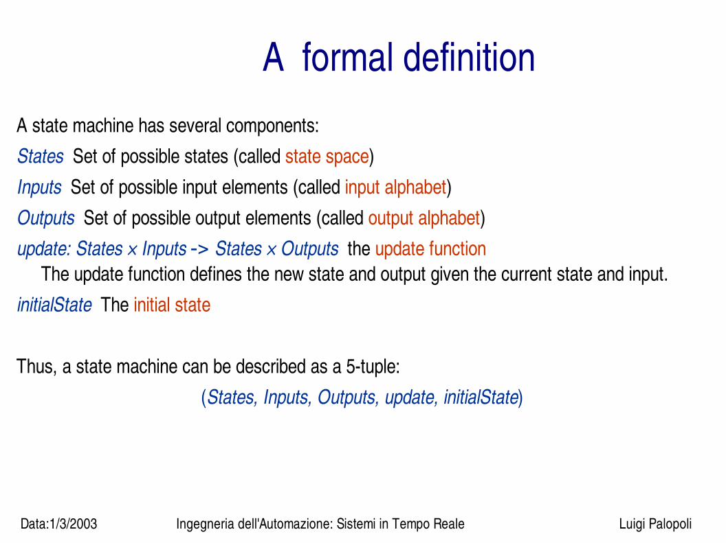
A formal definitionA state machine has several components:States Set of possible states (called state space)Inputs Set of possible input elements (called input alphabet)Outputs Set of possible output elements (called output alphabet)update: States × Inputs -> States × Outputs the update function
The update function defines the new state and output given the current state and input.initialState The initial state
Thus, a state machine can be described as a 5tuple: (States, Inputs, Outputs, update, initialState)

Data:1/3/2003 Ingegneria dell'Automazione: Sistemi in Tempo Reale Luigi Palopoli
Update ● SM are causal: output depends only on the current state (that
summarises the past history of the system) and on the current inputs
● The update dunction is often split into two functions:
nextState : States×InputsStates , s n1=nextState s n , x noutput : States×inputsoutputs y n=output s n , x n
Data:1/3/2003 Ingegneria dell'Automazione: Sistemi in Tempo Reale Luigi Palopoli
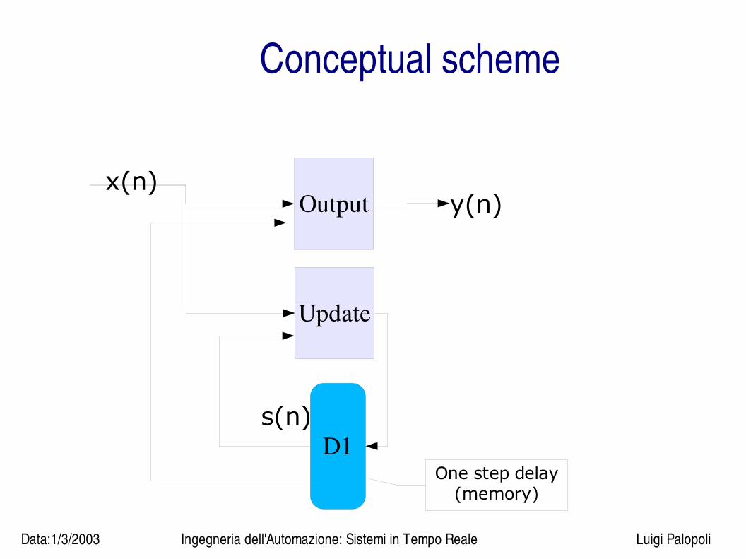
Conceptual scheme
Update
Output
D1
x(n)y(n)
s(n)
One step delay(memory)

Data:1/3/2003 Ingegneria dell'Automazione: Sistemi in Tempo Reale Luigi Palopoli
StutteringWe define a special “do nothing” input called absent.When x(n) = absent, ● the state does not change, so s(n+1) = s(n);● the output is also “nothing”, i. e. y(n) = absent.● We can always add absent symbols to input sequences without changing non
absent outputs
This symbol, absent, is called the stuttering symbol.
Note that this symbol is always a possible input and output, so
absent∈Inputs , absent∈Outputs
Data:1/3/2003 Ingegneria dell'Automazione: Sistemi in Tempo Reale Luigi Palopoli
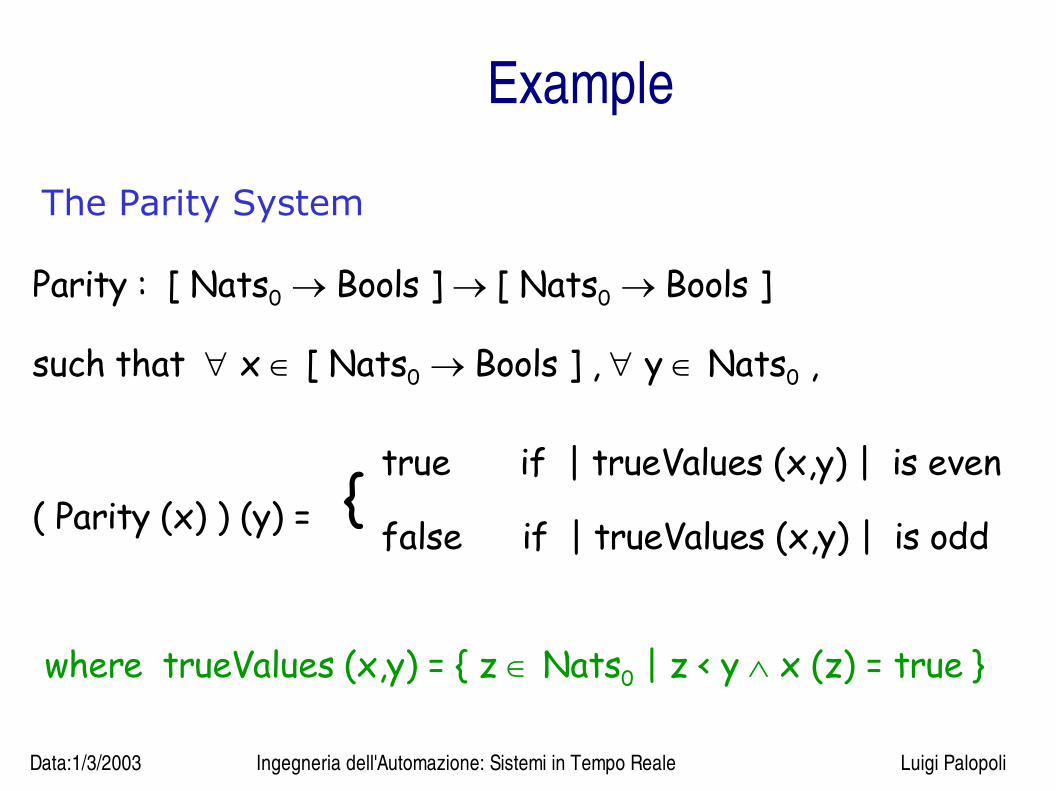
Example
The Parity System
Parity : [ Nats0 Bools ] [ Nats0 Bools ]
such that x [ Nats0 Bools ] , y Nats0 ,
( Parity (x) ) (y) = true if | trueValues (x,y) | is even
false if | trueValues (x,y) | is odd {
where trueValues (x,y) = { z Nats0 | z < y x (z) = true }

Data:1/3/2003 Ingegneria dell'Automazione: Sistemi in Tempo Reale Luigi Palopoli
Example (continued)
State-Machine Implementation of the Parity System
State after i-th input :
true, if first i inputs contain even number of true’s
false, if first i inputs contain odd number of true’s
Two states
Data:1/3/2003 Ingegneria dell'Automazione: Sistemi in Tempo Reale Luigi Palopoli
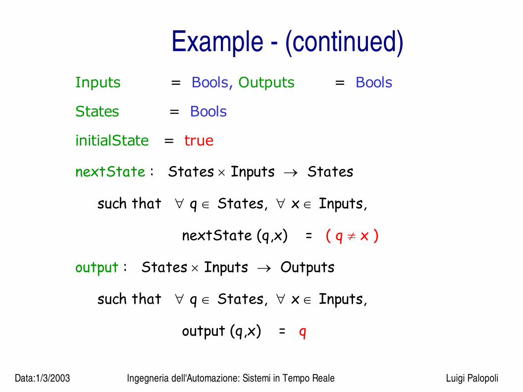
Example (continued)Inputs = Bools, Outputs = Bools
States = Bools
initialState = true
nextState : States Inputs States
such that q States, x Inputs,
nextState (q,x) = ( q x )
output : States Inputs Outputs
such that q States, x Inputs,
output (q,x) = q

Data:1/3/2003 Ingegneria dell'Automazione: Sistemi in Tempo Reale Luigi Palopoli
Example (continued)
Nats0 Bools Nats0 Bools
Dtrue Nats0 BoolsNats0 Bools
Parity
Data:1/3/2003 Ingegneria dell'Automazione: Sistemi in Tempo Reale Luigi Palopoli
FSM
● Both examples shown above have a common features: A finite number of states
● For this reason they are called Finite State Machines ● We will also restrict to the case of finite input and output
alphabet
Data:1/3/2003 Ingegneria dell'Automazione: Sistemi in Tempo Reale Luigi Palopoli
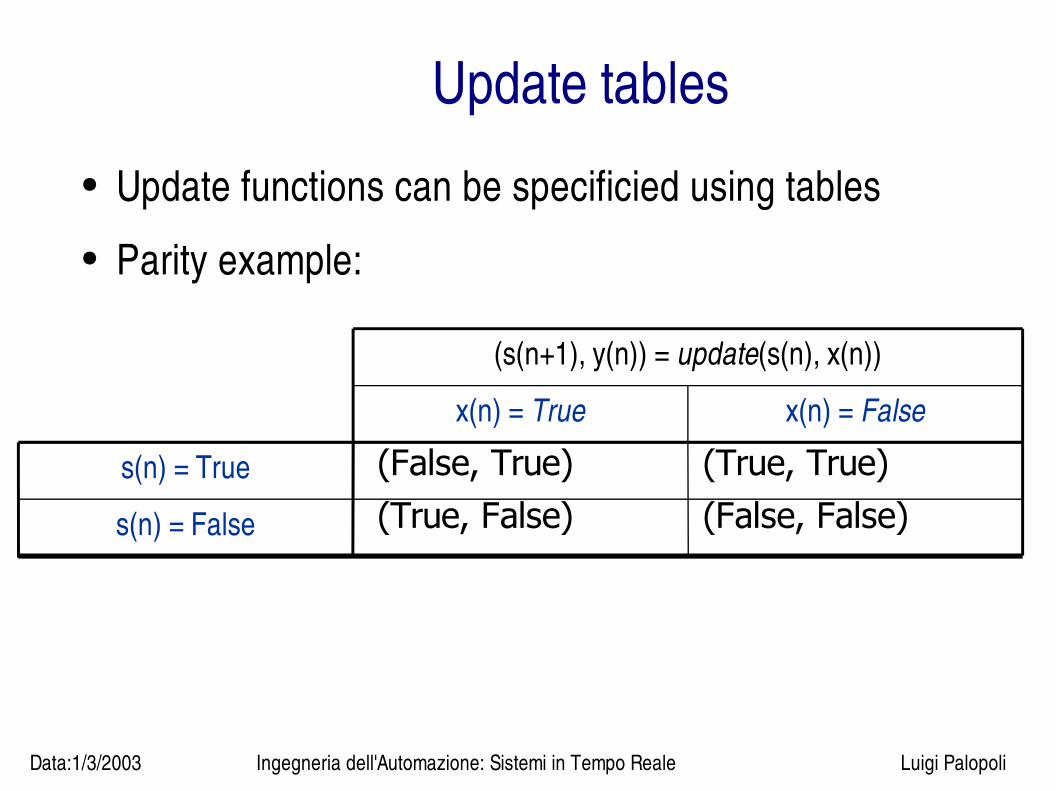
Update tables● Update functions can be specificied using tables● Parity example:
s(n) = False
s(n) = True
x(n) = Falsex(n) = True
(s(n+1), y(n)) = update(s(n), x(n))
(False, True) (True, True)(True, False) (False, False)
Data:1/3/2003 Ingegneria dell'Automazione: Sistemi in Tempo Reale Luigi Palopoli
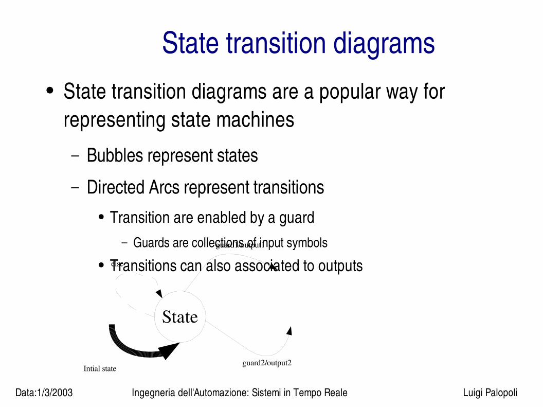
State transition diagrams● State transition diagrams are a popular way for
representing state machines– Bubbles represent states
– Directed Arcs represent transitions● Transition are enabled by a guard
– Guards are collections of input symbols● Transitions can also associated to outputs
State
guard1/output1
guard2/output2
else
Intial state
Data:1/3/2003 Ingegneria dell'Automazione: Sistemi in Tempo Reale Luigi Palopoli
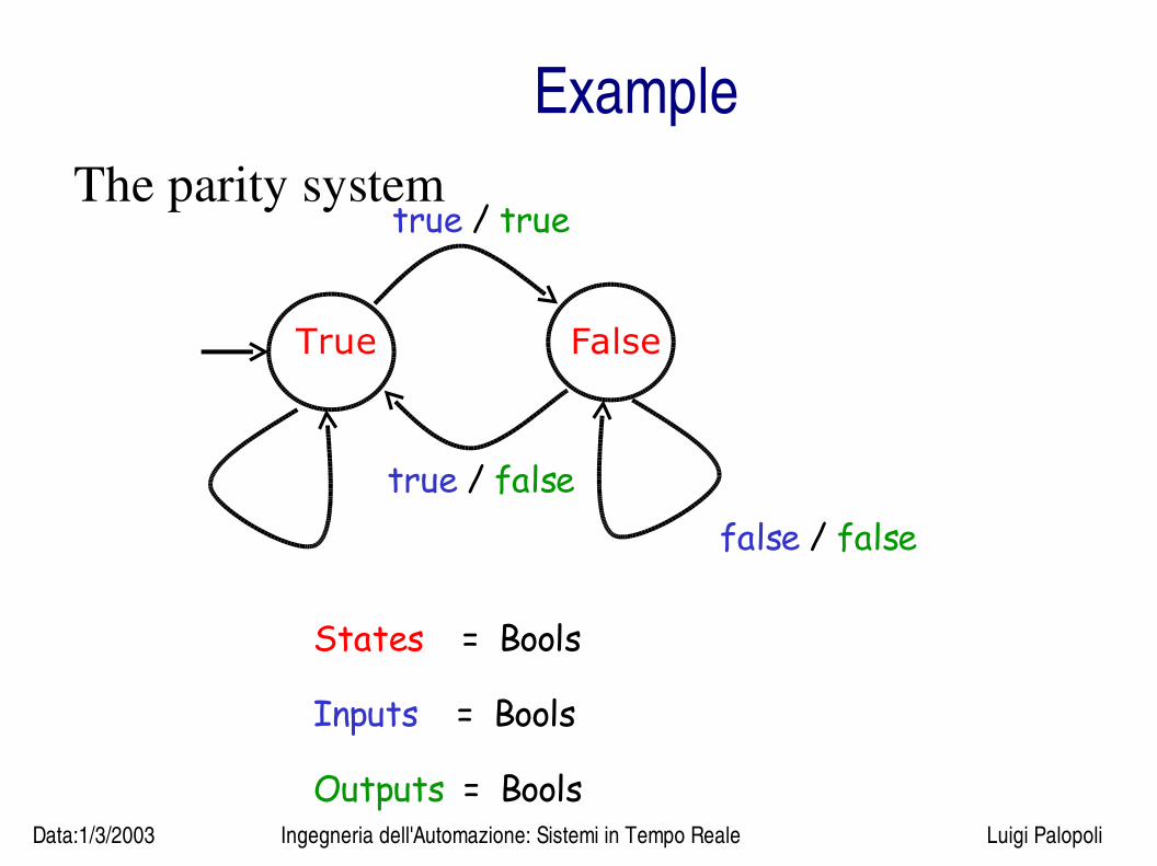
ExampleThe parity system
True False
true / true
true / falsefalse / false
States = Bools
Inputs = Bools
Outputs = Bools
Data:1/3/2003 Ingegneria dell'Automazione: Sistemi in Tempo Reale Luigi Palopoli
Shorthand
● If no guard is specified the transition is always taken (except for the stuttering symbol)
● If no output symbol is specified then the output is the stuttering symbol
● If no else transition is specified then we assume a self loop
● If inputs are {a,b,c,d,...,z} we can use {not a} in a guard instead of {b,c,...,z}
Data:1/3/2003 Ingegneria dell'Automazione: Sistemi in Tempo Reale Luigi Palopoli
Excercise
Draw the transition diagram of a state machine with
Inputs = Bools
Outputs = Bools
At all times t, the output is true iff the
inputs at times t-2, t-1, and t are all
true .

Data:1/3/2003 Ingegneria dell'Automazione: Sistemi in Tempo Reale Luigi Palopoli
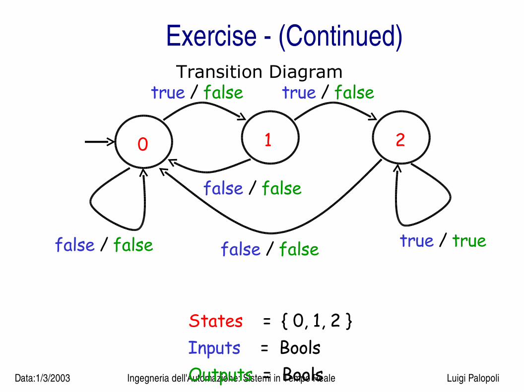
Exercise (continued)
State after i-th input :
0, if i-th input is false ( or i = 0 )
1, if i-th input is true and (i-1)-st input is false
2, if both i-th and (i-1)-st inputs are true
Three states
( or i = 1 )
Data:1/3/2003 Ingegneria dell'Automazione: Sistemi in Tempo Reale Luigi Palopoli
Exercise (Continued)Transition Diagram
States = { 0, 1, 2 } Inputs = Bools Outputs = Bools
0 21
true / false
false / false
false / false false / false true / true
true / false

Data:1/3/2003 Ingegneria dell'Automazione: Sistemi in Tempo Reale Luigi Palopoli
Some terminology
● Receptiveness: our SM always react to a symbol (there is an outgoing arc specified, or an else arc either specified or implied)
● Determinism: a SM is said deterministic if every input symbols is contained in one and only one outgoing arc
● State transitions triggered by a sequence of inputs are called State response
● A finite machine without output is called finite automata

Data:1/3/2003 Ingegneria dell'Automazione: Sistemi in Tempo Reale Luigi Palopoli
Some definitions (continued)● The state machines addressed here are called Mealy machines. Mealy machines
generate outputs during state transitions.
• Moore machines generate output while the system is in a particular state (output depends on state only).
Update
Output
D1
x(n)y(n)
s(n)
Mealy
Update
Output
D1
x(n)
y(n)
s(n)
Moore
Data:1/3/2003 Ingegneria dell'Automazione: Sistemi in Tempo Reale Luigi Palopoli
Some facts
– A SM is statedetermined: Each transition and output depends only on the current state and current input.
• Previous input elements only affect the transitions and output insofar as they determine the current state.
– A representation of a SM may not be unique
– Representations of a SM
• Update tables (useful in computer implementations)
• State transition diagrams (human friendly)
• Sets and Functions (useful for mathematical purposes)
Data:1/3/2003 Ingegneria dell'Automazione: Sistemi in Tempo Reale Luigi Palopoli
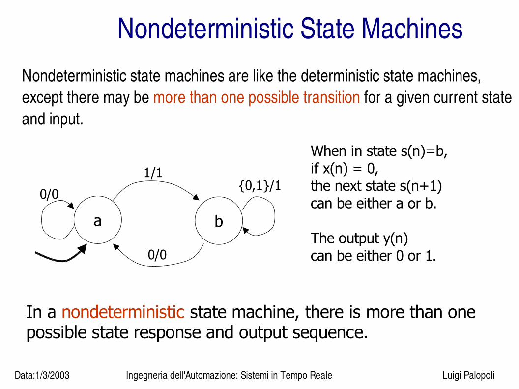
Nondeterministic State MachinesNondeterministic state machines are like the deterministic state machines, except there may be more than one possible transition for a given current state and input.
a b
0/0
1/1{0,1}/1
0/0
When in state s(n)=b,if x(n) = 0,the next state s(n+1)can be either a or b.
The output y(n)can be either 0 or 1.
In a nondeterministic state machine, there is more than one possible state response and output sequence.

Data:1/3/2003 Ingegneria dell'Automazione: Sistemi in Tempo Reale Luigi Palopoli
Nodeterministic State Machines: PartsNondeterministic state machines are described with the 5tuple:
(States, Inputs, Outputs, possibleUpdates, initialState)
The update function is now called possibleUpdates.
For a given input x(n) and current state s(n), possibleUpdates provides the set of possible next states s(n+1) and outputs y(n).
possibleUpdates: States × Inputs -> P(States × Outputs)
Here, the notation P() denotes the power set. For some set S, P(S) is the set of all subsets of S.
Data:1/3/2003 Ingegneria dell'Automazione: Sistemi in Tempo Reale Luigi Palopoli
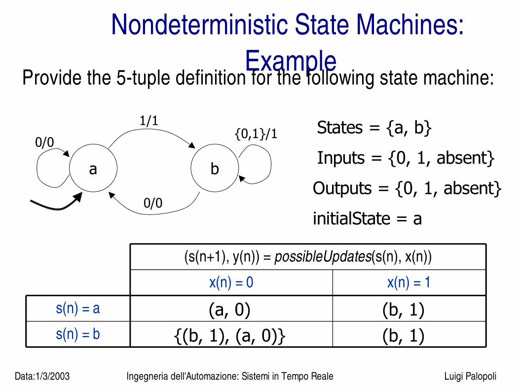
Nondeterministic State Machines: Example
Provide the 5tuple definition for the following state machine:
a b
0/0
1/1{0,1}/1
0/0
States = {a, b}
Inputs = {0, 1, absent}
Outputs = {0, 1, absent}
initialState = a
s(n) = b
s(n) = a
x(n) = 1x(n) = 0
(s(n+1), y(n)) = possibleUpdates(s(n), x(n))
(a, 0) (b, 1){(b, 1), (a, 0)} (b, 1)
Data:1/3/2003 Ingegneria dell'Automazione: Sistemi in Tempo Reale Luigi Palopoli
Why nondeterminism?
-modeling randomness
-modeling abstraction
-...
Data:1/3/2003 Ingegneria dell'Automazione: Sistemi in Tempo Reale Luigi Palopoli
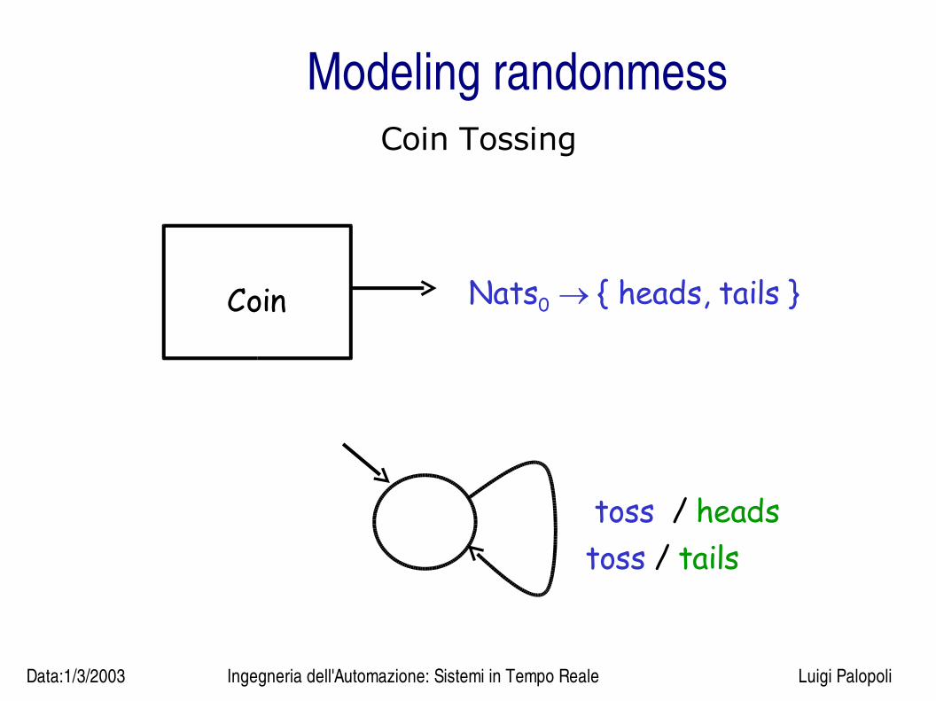
Modeling randonmessCoin Tossing
toss / headstoss / tails
Coin Nats0 { heads, tails }
Data:1/3/2003 Ingegneria dell'Automazione: Sistemi in Tempo Reale Luigi Palopoli
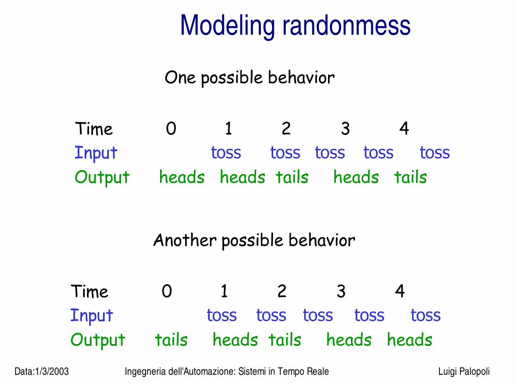
Modeling randonmess
One possible behavior
Time 0 1 2 3 4Input toss toss toss toss tossOutput heads heads tails heads tails
Another possible behavior
Time 0 1 2 3 4Input toss toss toss toss tossOutput tails heads tails heads heads

Data:1/3/2003 Ingegneria dell'Automazione: Sistemi in Tempo Reale Luigi Palopoli
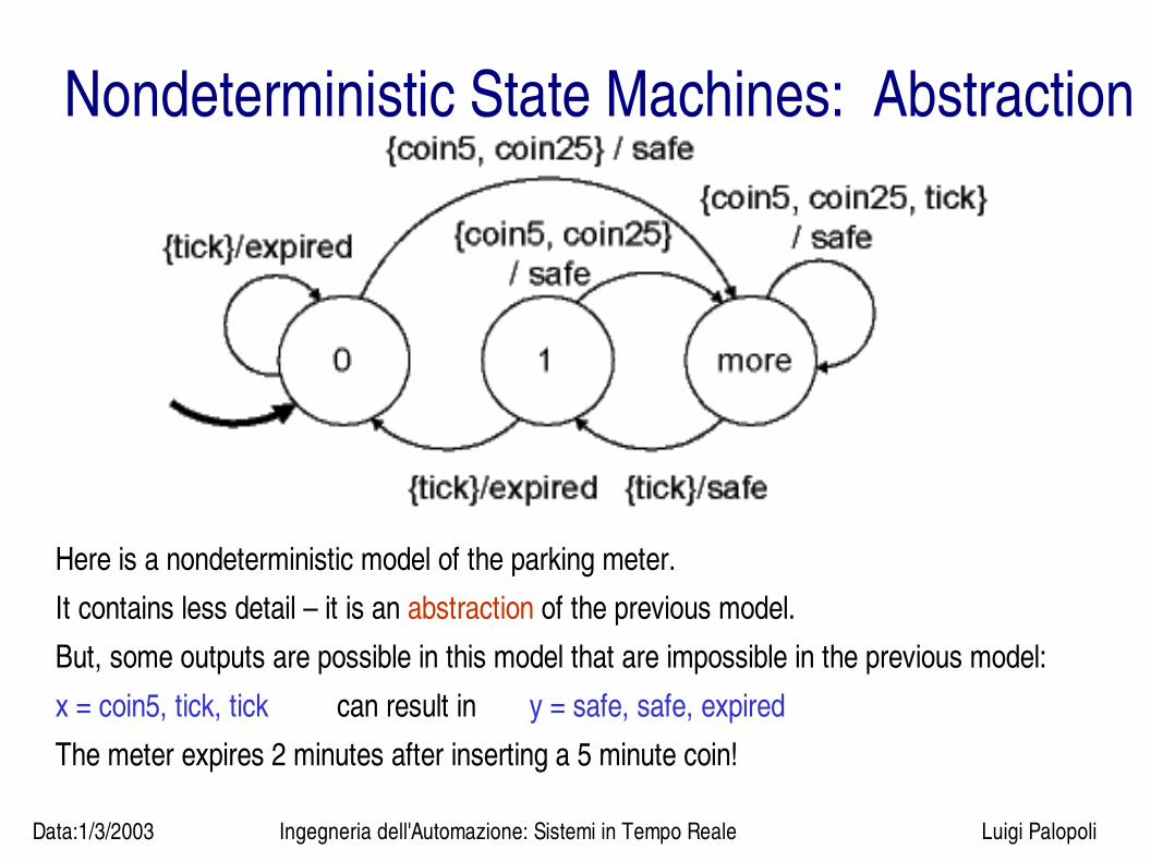
Nondeterministic State Machines: Abstraction
This example is a deterministic model of a parking meter.The inputs are coin5 (5 minutes) coin25 (25 minutes) and tick.The outputs are safe and expired.The states represent the number of minutes left until expiration.This model of meter operation is accurate, but complicated!
Data:1/3/2003 Ingegneria dell'Automazione: Sistemi in Tempo Reale Luigi Palopoli
Here is a nondeterministic model of the parking meter.It contains less detail – it is an abstraction of the previous model.But, some outputs are possible in this model that are impossible in the previous model:x = coin5, tick, tick can result in y = safe, safe, expiredThe meter expires 2 minutes after inserting a 5 minute coin!
Nondeterministic State Machines: Abstraction
Data:1/3/2003 Ingegneria dell'Automazione: Sistemi in Tempo Reale Luigi Palopoli
State Machines: Behaviors
A behavior of a state machine is a pair (x, y) where x is an input sequence and y is a corresponding output sequence:
Behaviors = {(x, y)[Naturals0>Inputs]×[Naturals0>Outputs] | y is a possible output sequence for the input x}

Data:1/3/2003 Ingegneria dell'Automazione: Sistemi in Tempo Reale Luigi Palopoli
Deterministic behaviours
Deterministic SM:
for every input signal, there is exactly one output signal.
DetSys : [ Nats Inputs ] [ Nats Outputs ]
Behavoiurs is the graph of a Function:

Data:1/3/2003 Ingegneria dell'Automazione: Sistemi in Tempo Reale Luigi Palopoli
Nondeterministic behavioursNondeterministic Reactive System:
for every input signal, there is one or more output signals.
NondetSys [ Nats Inputs ] [ Nats Outputs ]
such that x [ Nats Inputs ], y [ Nats Outputs ], (x,y) NondetSys
Behaviours are a Binary relation:
Every pair (x,y) NondetSys is called a behavior.
Data:1/3/2003 Ingegneria dell'Automazione: Sistemi in Tempo Reale Luigi Palopoli
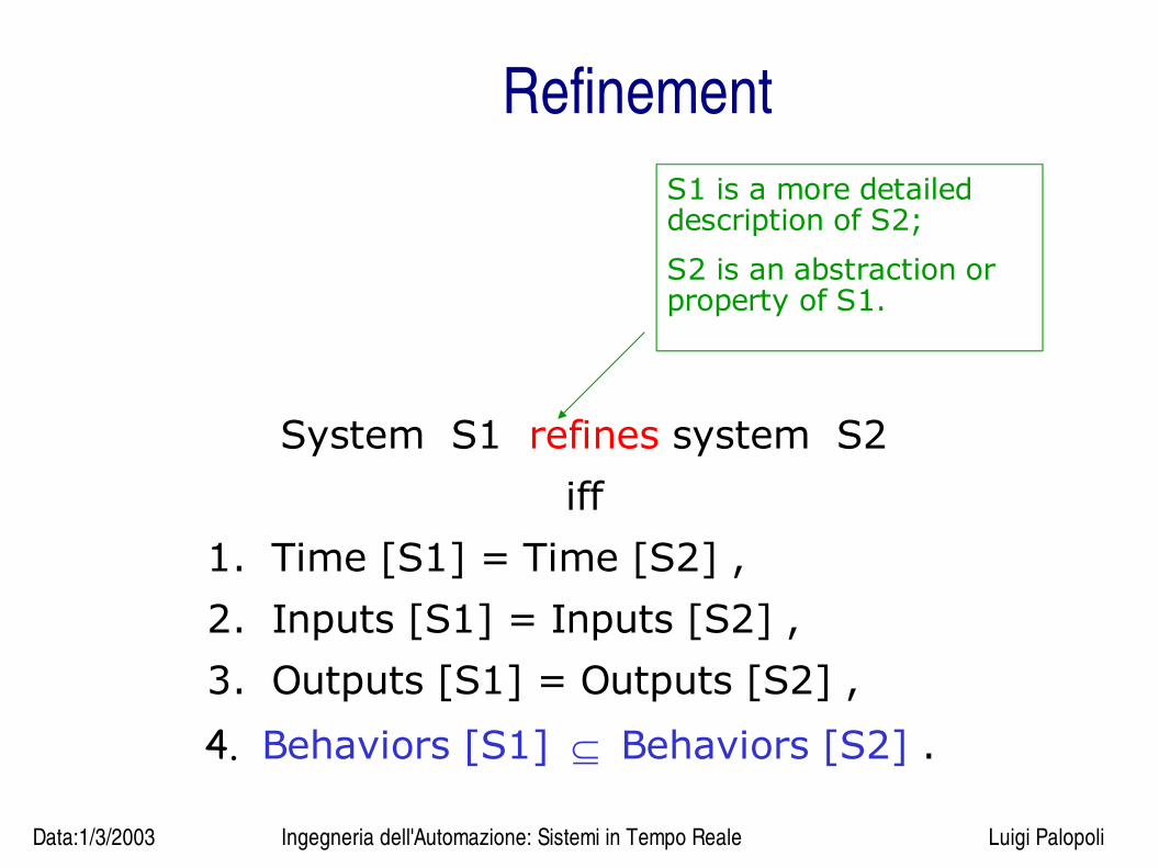
System S1 refines system S2
iff
1. Time [S1] = Time [S2] ,
2. Inputs [S1] = Inputs [S2] ,
3. Outputs [S1] = Outputs [S2] ,
4. Behaviors [S1] Behaviors [S2] .
S1 is a more detailed description of S2;
S2 is an abstraction or property of S1.
Refinement
Data:1/3/2003 Ingegneria dell'Automazione: Sistemi in Tempo Reale Luigi Palopoli
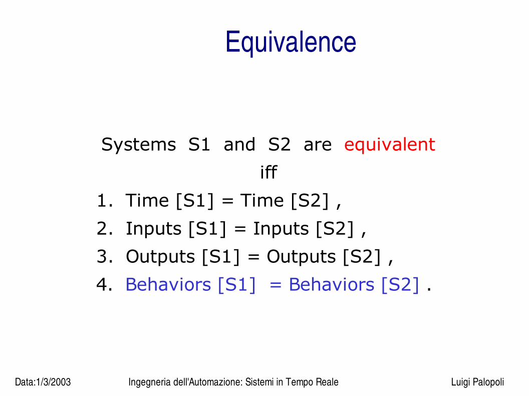
Equivalence
Systems S1 and S2 are equivalent
iff
1. Time [S1] = Time [S2] ,
2. Inputs [S1] = Inputs [S2] ,
3. Outputs [S1] = Outputs [S2] ,
4. Behaviors [S1] = Behaviors [S2] .

Data:1/3/2003 Ingegneria dell'Automazione: Sistemi in Tempo Reale Luigi Palopoli
SimulationA binary relation S States [M1] States [M2] is a simulation of M1 by
M2 iff
1. p possibleInitialStates [M1] ,
q possibleInitialStates [M2], ( p, q ) S and
2. p States [M1] , q States [M2] ,
if ( p, q ) S , then x Inputs , y Outputs , p’ States [M1] ,
if ( p’, y ) possibleUpdates [M1] ( p, x )
then q’ States [M2] ,
( q’, y ) possibleUpdates [M2] ( q, x ) and
( p’, q’ ) S .
Data:1/3/2003 Ingegneria dell'Automazione: Sistemi in Tempo Reale Luigi Palopoli
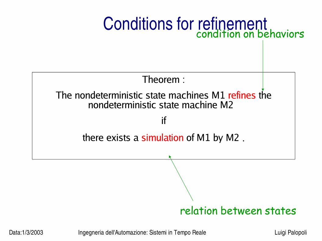
Conditions for refinement
Theorem :
The nondeterministic state machines M1 refines the nondeterministic state machine M2
if
there exists a simulation of M1 by M2 .
condition on behaviors
relation between states
Data:1/3/2003 Ingegneria dell'Automazione: Sistemi in Tempo Reale Luigi Palopoli
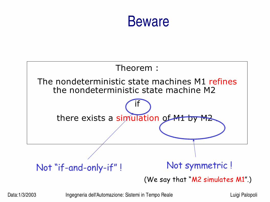
Beware
Theorem :
The nondeterministic state machines M1 refines the nondeterministic state machine M2
if
there exists a simulation of M1 by M2 .
Not “if-and-only-if” ! Not symmetric ! (We say that “M2 simulates M1”.)

Data:1/3/2003 Ingegneria dell'Automazione: Sistemi in Tempo Reale Luigi Palopoli
Intuition
● The theorem simply states that M2 can match every move of m1 producing
the same output ● Moreover, if M2 cannot produce an output sequence, neither can M1, as
stated below:
Corollary:
Let M2 simulate M1. If (x,y)BehavioursM2
then
(x,y) BehavioursM1
.
Data:1/3/2003 Ingegneria dell'Automazione: Sistemi in Tempo Reale Luigi Palopoli
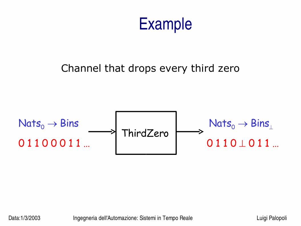
Example
Channel that drops every third zero
Nats0 BinsNats0 Bins
0 1 1 0 0 0 1 1 … 0 1 1 0 0 1 1 …ThirdZero
Data:1/3/2003 Ingegneria dell'Automazione: Sistemi in Tempo Reale Luigi Palopoli
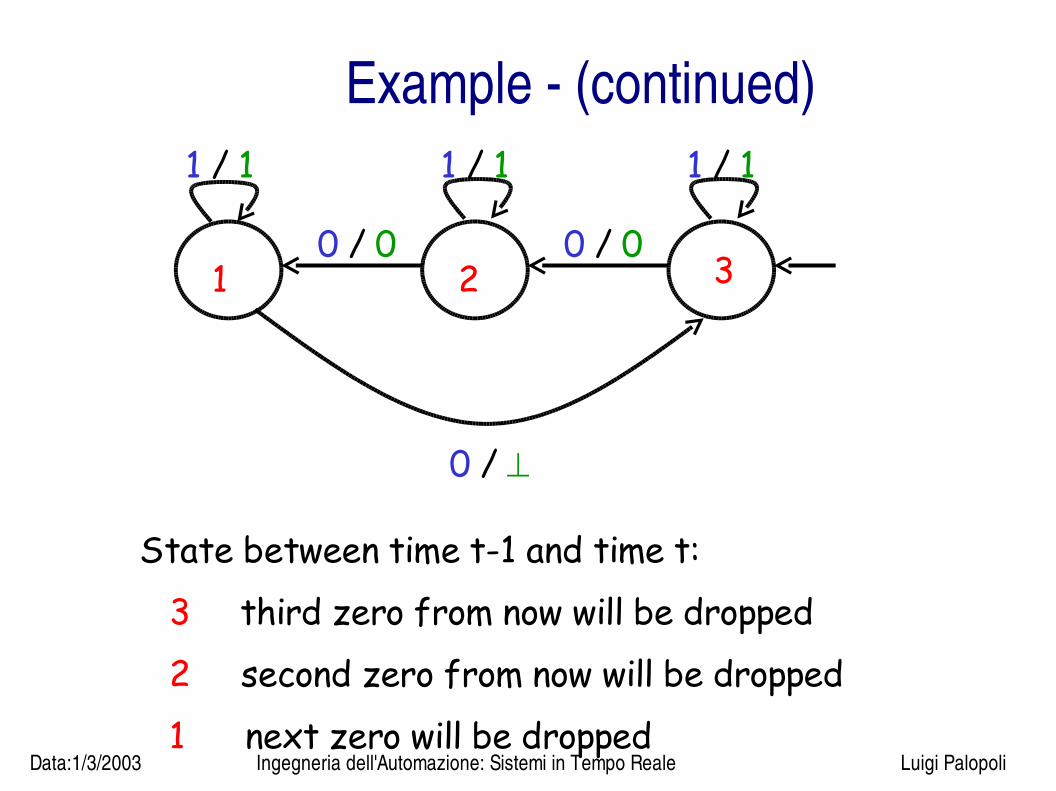
Example (continued)
State between time t-1 and time t: 3 third zero from now will be dropped 2 second zero from now will be dropped 1 next zero will be dropped
1 32
0 /
0 / 00 / 0
1 / 1 1 / 11 / 1
Data:1/3/2003 Ingegneria dell'Automazione: Sistemi in Tempo Reale Luigi Palopoli
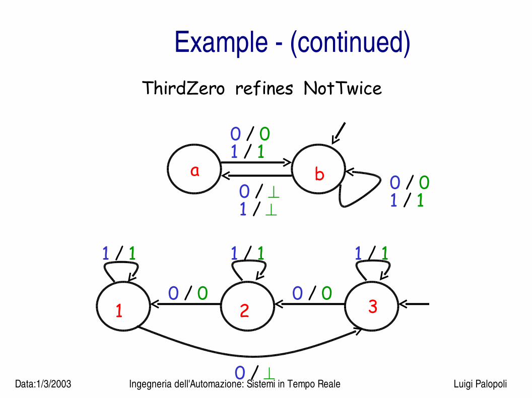
Example (continued)ThirdZero refines NotTwice
a b 0 / 01 / 1
0 / 0
1 / 0 /
1 / 1
1 32
0 /
0 / 00 / 0
1 / 1 1 / 11 / 1
Data:1/3/2003 Ingegneria dell'Automazione: Sistemi in Tempo Reale Luigi Palopoli
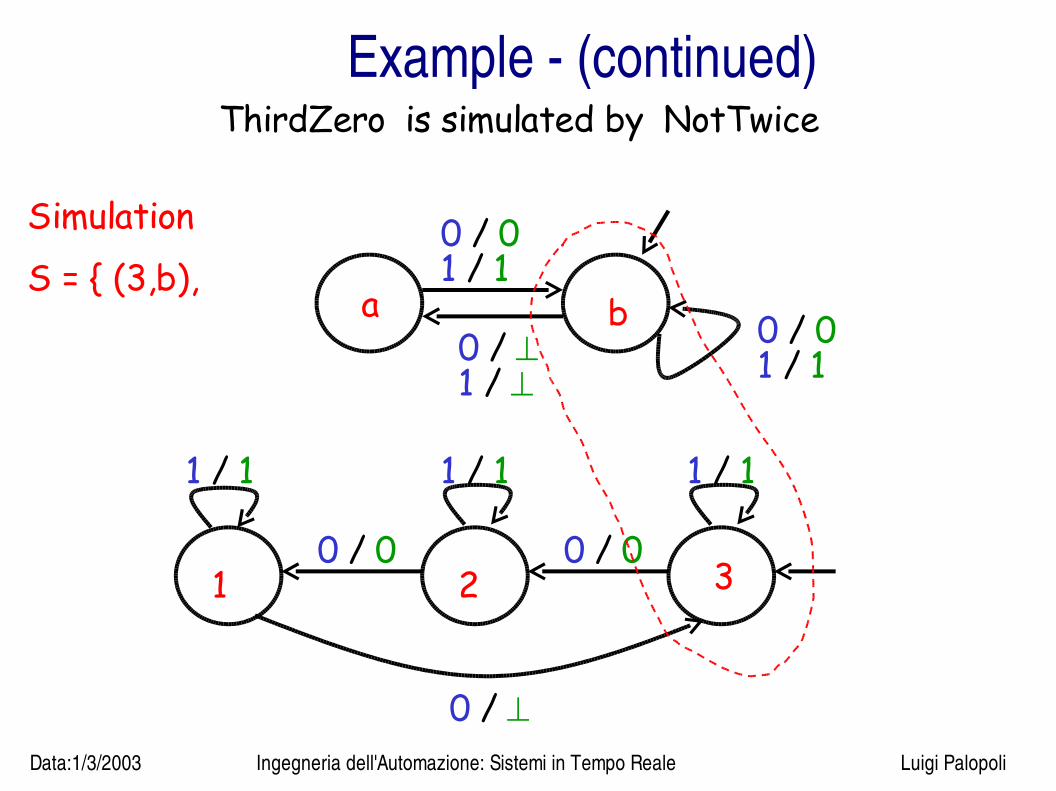
Example (continued)ThirdZero is simulated by NotTwice
a b 0 / 01 / 1
0 / 0
1 / 0 /
1 / 1
1 32
0 /
0 / 00 / 0
1 / 1 1 / 11 / 1
Simulation S = { (3,b),
Data:1/3/2003 Ingegneria dell'Automazione: Sistemi in Tempo Reale Luigi Palopoli
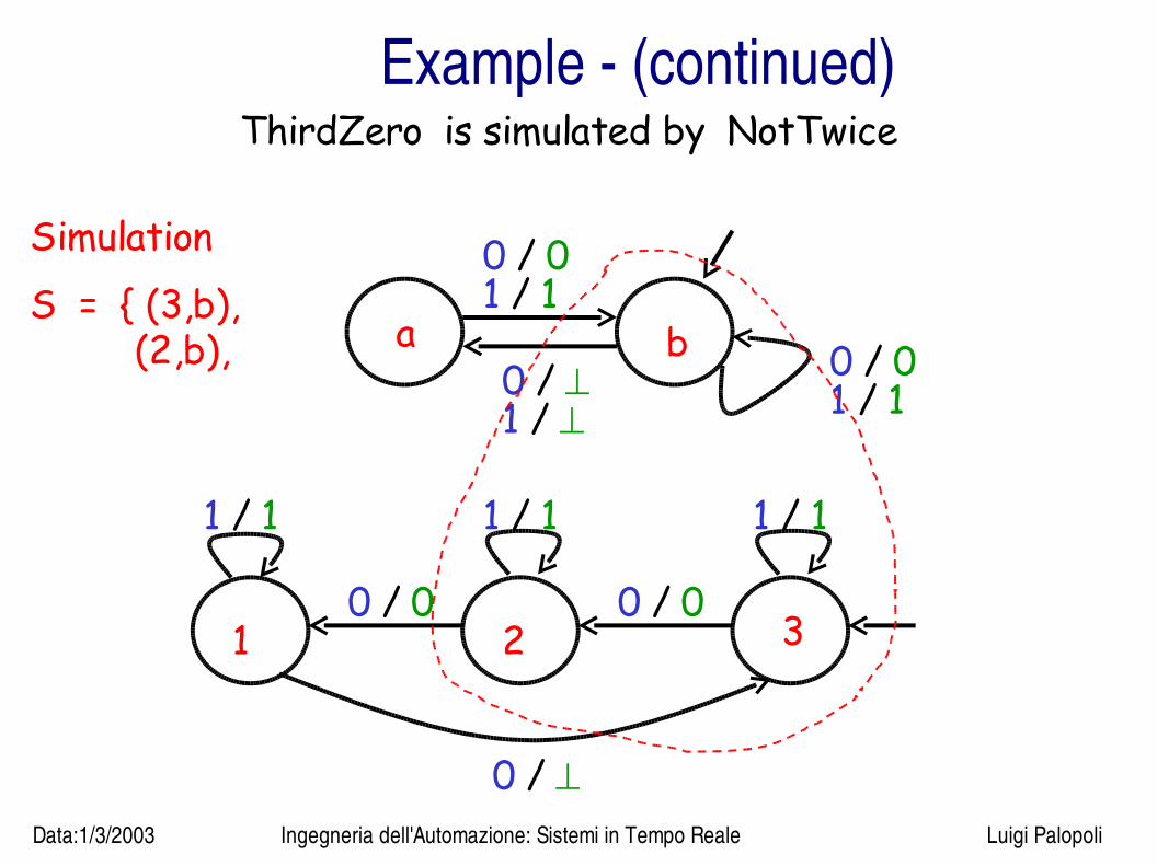
Example (continued)ThirdZero is simulated by NotTwice
a b 0 / 01 / 1
0 / 0
1 / 0 /
1 / 1
1 32
0 /
0 / 00 / 0
1 / 1 1 / 11 / 1
Simulation S = { (3,b), (2,b),

Data:1/3/2003 Ingegneria dell'Automazione: Sistemi in Tempo Reale Luigi Palopoli
Example (continued)ThirdZero is simulated by NotTwice
a b 0 / 01 / 1
0 / 0
1 / 0 /
1 / 1
1 32
0 /
0 / 00 / 0
1 / 1 1 / 11 / 1
Simulation S = { (3,b), (2,b),(1,b),
Data:1/3/2003 Ingegneria dell'Automazione: Sistemi in Tempo Reale Luigi Palopoli
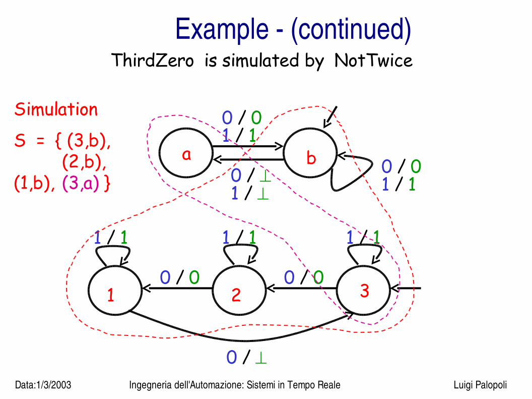
Example (continued)ThirdZero is simulated by NotTwice
a b 0 / 01 / 1
0 / 0
1 / 0 /
1 / 1
1 32
0 /
0 / 00 / 0
1 / 1 1 / 11 / 1
Simulation S = { (3,b), (2,b),(1,b), (3,a) }
Data:1/3/2003 Ingegneria dell'Automazione: Sistemi in Tempo Reale Luigi Palopoli
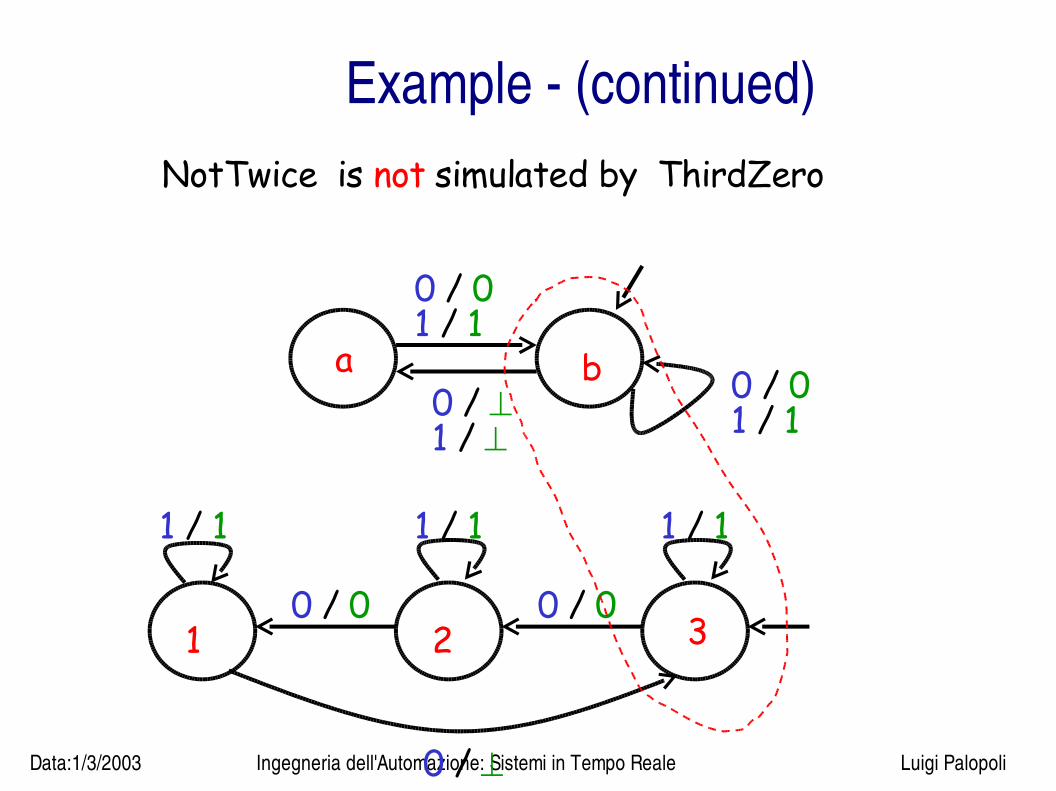
Example (continued)NotTwice is not simulated by ThirdZero
a b 0 / 01 / 1
0 / 0
1 / 0 /
1 / 1
1 32
0 /
0 / 00 / 0
1 / 1 1 / 11 / 1

Data:1/3/2003 Ingegneria dell'Automazione: Sistemi in Tempo Reale Luigi Palopoli
Example (continued)NotTwice is not simulated by ThirdZero
a b 0 / 01 / 1
0 / 0
1 / 0 /
1 / 1
1 32
0 /
0 / 00 / 0
1 / 1 1 / 11 / 1
X 0 /

Data:1/3/2003 Ingegneria dell'Automazione: Sistemi in Tempo Reale Luigi Palopoli
Remark
● If M2 satisfies a property, so does M1● For instance, insofar as the property nottwice, is of
interest, we can prove it on NotTwice and it also applies to ThirdZero
Data:1/3/2003 Ingegneria dell'Automazione: Sistemi in Tempo Reale Luigi Palopoli
Remark 1
If M2 is a deterministic state machine, then
M1 is simulated by M2
iff
M1 is equivalent to M2.
Data:1/3/2003 Ingegneria dell'Automazione: Sistemi in Tempo Reale Luigi Palopoli
Remark 2If M2 is a nondeterministic state machine, then
M1 is simulated by M2
implies
M1 refines M2,
but M2 may not refine M1.
( Recall M1 = ThirdZero and M2 = NotTwice .)