L8542271 03/2011 rev 2 BOB 50M BOB 50ME - ssc · l8542271 03/2011 rev 2 bob 50m bob 50me unione...
24
L8542271 03/2011 rev 2 BOB 50M BOB 50ME UNIONE NAZIONALE COSTRUTTORI AUTOMATISMI PER CANCELLI, PORTE SERRANDE ED AFFINI
Transcript of L8542271 03/2011 rev 2 BOB 50M BOB 50ME - ssc · l8542271 03/2011 rev 2 bob 50m bob 50me unione...
L854227103/2011 rev 2
BOB 50M BOB 50ME
UNIONE NAZIONALE COSTRUTTORIAUTOMATISMI PER CANCELLI, PORTE
SERRANDE ED AFFINI

3
455
/ 48
5 /
520
857
100
87
48
70
107
980
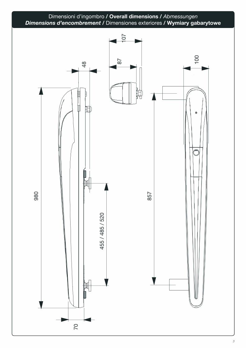
Dimensioni d’ingombro / Overall dimensions / AbmessungenDimensions d’encombrement / Dimensiones exteriores / Wymiary gabarytowe

4
1
Apertura maxMax OpeningMax. Öffung
Ouverture maxAbiertura max.
X Y Z K M*max.
Tempo aperturaOpening time
ÖffungszeitTemps d'ouvertureTiempo de abierturaPrędkość kątowa
(90°)
Dimensioni max antaMax wing dimensions
Max FlügelmasseDimens. max de la porteDimens. max de la hoja
L (m) P (kg)
90 150 150 75 695 90 25”
2,5 450
3 400
3,5 350
4* 300
90 225 225 130 625 155 38”
2,5 600
3 550
3,5 500
4* 400
4,5* 350
5* 300
100 200 200 110 650 130 34”
2,5 600
3 550
3,5 500
4* 400
4,5* 350
5* 300
110 175 175 90 680 110 30”
2,5 450
3 400
3,5 350
4* 300
XK
P S
Y
MZ
M
Y
X
90°
110°max
M = +20mm / K = -10mm
Fig. 1a
Fig. 1b
* Consigliabile l’utilizzo di elettroserratura* It is advisable to use an electric lock* Wir empfehlen den Einsatz eines Elektroschlosses* On suggère l’utilisation d’une serrure électrique* Aconsejado el empleo de la cerradura eléctrica* Zaleca się zainstalowanie zamka elektrycznego
5
3
2
V1
V2
BB
P
F
D
P
S V
R
C
T
Mettere a livello.Level.Nivellieren.Mettre de niveau.Nivelar.Ustawić na wysokości
Saldare.Weld.Anschweißen.Souder.Soldar.Spawać
Saldare.Weld.Anschweißen.Souder.Soldar.Spawać.
GrassoGrease Fett Graisse GrasaSmar
6
4
5
VP
Posizione 2 (PG11)Position 2 (PG11)Position 2 (PG11)Position 2 (PG11)Posición 2 (PG11)Pozycja 2 (PG11)
Posizione 1 (PG13,5)Position 1 (PG13,5)Position 1 (PG13,5)Position 1 (PG13,5)Posición 1 (PG13,5)Pozycja 1 (PG13,5)
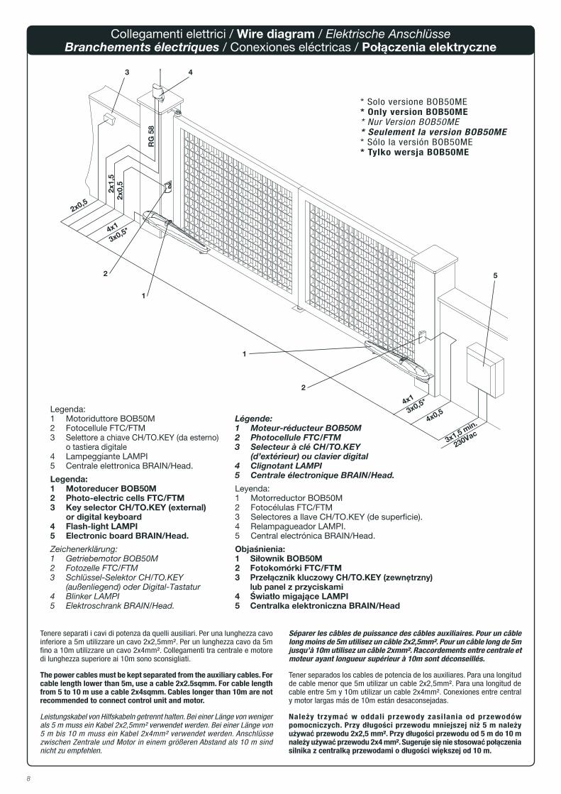
Condensatore 9μFCapacitor 9μFKondensator 9μFCondensateur 9μFCondensador 9μFKondensator 9μF
Cavo alimentazionePower supply cableStromkabelCâble d’alimentationCable de alimentaciónKabel zasilania
Raccordo per guaina o pressacavoConnection for sheath and cable glandAnschluss für Hülse oder KabelhalterRaccord pour gaine o serre-câbleEmpalme para vaina o prensaestopasZłącze do osłony lub dławika kablowego
MorsettieraTerminal boardKlemmleisteBoîte à jointsRegleteroListwa zaciskowa

7
6
1 Chiude Close Schließen Ferme Cierra Zamyka
2 Apre Open Öffnen Ouvre Abre Otwiera
3 COM COM COM COM COM COM
4 GND GND GND GND GND GND
5 Segnale ENCODER ENCODER signal ENCODER-Signal Signal ENCODEUR Señal ENCODER Sygnał ENKODERA
6 Positivo ENCODER ENCODER positive ENCODER Pluspol Positif ENCODEUR Positivo ENCODER Dodatni ENKODERA
7 Negativo ENCODER ENCODER negative ENCODER Minuspol Négatif ENCODER Negativo ENCODER Ujemny ENKODERA
a Filo nero Black wire Schwarzer Leiter Fil noir Hilo negro Czarny przewód
b Filo bianco White wire Weißer Leiter Fil blanc Hilo blanco Biały przewód
c Filo rosso Red wire Roter Leiter Fil rouge Hilo rojo Czerwony przewód
FCC Finecorsa CHIUDE CLOSE limit switch Endschalter SCHLIESSEN Fin de course FERME Final de carrera CIERRA Ogranicznik ZAMYKA
FCO Finecorsa APRE OPEN limit switch Endschalter ÖFFNEN Fin de course OUVRE Final de carrera ABRE Ogranicznik OTWIERA
Mb
ac
1 2 3 4
GND
1 2 3 4
a
b
c
5 6 7
GNDM
EncoderEncoderEncoderCodeurEncoderEnkoder
M
1
ba
c
2 3 4GND
FCO
FCC
b ac
FCO
2 3
GND
41
M
a
Mb
ac
1 2 3 4
GND
1 2 3 4
a
b
c
5 6 7
GNDM
EncoderEncoderEncoderCodeurEncoderEnkoder
M
1
ba
c
2 3 4
GND
FCO
FCC
b ac
FCO
2 3
GND
41
M
b
Mb
ac
1 2 3 4
GND
1 2 3 4
a
b
c
5 6 7GNDM
EncoderEncoderEncoderCodeurEncoderEnkoder
M
1
ba
c
2 3 4
GND
FCO
FCC
b ac
FCO
2 3
GND
41
M
c
Mb
ac
1 2 3 4
GND
1 2 3 4
a
b
c
5 6 7
GNDM
EncoderEncoderEncoderCodeurEncoderEnkoder
M
1
ba
c
2 3 4
GND
FCO
FCC
b ac
FCO
2 3
GND
41
M
d
8
3 4
2
1
5
3x1,5 min.
230Vac
2
1
2x1,
52x
0,5
2x0,5
4x1
4x1
3x0,5*
3x0,5*
4x0,5
RG
58
Légende:1 Moteur-réducteur BOB50M2 Photocellule FTC/FTM3 Selecteur à clé CH/TO.KEY (d’extérieur) ou clavier digital4 Clignotant LAMPI5 Centrale électronique BRAIN/Head.
Leyenda:1 Motorreductor BOB50M2 Fotocélulas FTC/FTM3 Selectores a llave CH/TO.KEY (de superficie).4 Relampagueador LAMPI.5 Central electrónica BRAIN/Head.
Objaśnienia:1 Siłownik BOB50M2 Fotokomórki FTC/FTM3 Przełącznik kluczowy CH/TO.KEY (zewnętrzny) lub panel z przyciskami4 Światło migające LAMPI5 Centralka elektroniczna BRAIN/Head
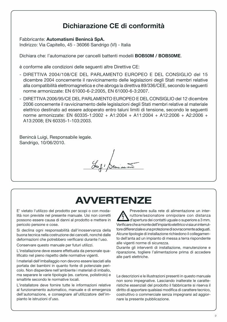
Legenda:1 Motoriduttore BOB50M2 Fotocellule FTC/FTM3 Selettore a chiave CH/TO.KEY (da esterno) o tastiera digitale4 Lampeggiante LAMPI5 Centrale elettronica BRAIN/Head.
Legenda:1 Motoreducer BOB50M2 Photo-electric cells FTC/FTM3 Key selector CH/TO.KEY (external) or digital keyboard4 Flash-light LAMPI5 Electronic board BRAIN/Head.
Zeichenerklärung:1 Getriebemotor BOB50M2 Fotozelle FTC/FTM3 Schlüssel-Selektor CH/TO.KEY (außenliegend) oder Digital-Tastatur4 Blinker LAMPI5 Elektroschrank BRAIN/Head.
Collegamenti elettrici / Wire diagram / Elektrische AnschlüsseBranchements électriques / Conexiones eléctricas / Połączenia elektryczne
Tenere separati i cavi di potenza da quelli ausiliari. Per una lunghezza cavo inferiore a 5m utilizzare un cavo 2x2,5mm². Per un lunghezza cavo da 5m fino a 10m utilizzare un cavo 2x4mm². Collegamenti tra centrale e motore di lunghezza superiore ai 10m sono sconsigliati.
The power cables must be kept separated from the auxiliary cables. For cable length lower than 5m, use a cable 2x2.5sqmm. For cable length from 5 to 10 m use a cable 2x4sqmm. Cables longer than 10m are not recommended to connect control unit and motor.
Leistungskabel von Hilfskabeln getrennt halten. Bei einer Länge von weniger als 5 m muss ein Kabel 2x2,5mm² verwendet werden. Bei einer Länge von 5 m bis 10 m muss ein Kabel 2x4mm² verwendet werden. Anschlüsse zwischen Zentrale und Motor in einem größeren Abstand als 10 m sind nicht zu empfehlen.
Séparer les câbles de puissance des câbles auxiliaires. Pour un câble long moins de 5m utilisez un câble 2x2,5mm². Pour un câble long de 5m jusqu’à 10m utilisez un câble 2xmm². Raccordements entre centrale et moteur ayant longueur supérieur à 10m sont déconseillés.
Tener separados los cables de potencia de los auxiliares. Para una longitud de cable menor que 5m utilizar un cable 2x2,5mm². Para una longitud de cable entre 5m y 10m utilizar un cable 2x4mm². Conexiones entre central y motor largas más de 10m están desaconsejadas.
Należy trzymać w oddali przewody zasilania od przewodów pomocniczych. Przy długości przewodu mniejszej niż 5 m należy używać przewodu 2x2,5 mm². Przy długości przewodu od 5 m do 10 m należy używać przewodu 2x4 mm². Sugeruje się nie stosować połączenia silnika z centralką przewodami o długości większej od 10 m.
* Solo versione BOB50ME* Only version BOB50ME* Nur Version BOB50ME* Seulement la version BOB50ME* Sólo la versión BOB50ME* Tylko wersja BOB50ME
9
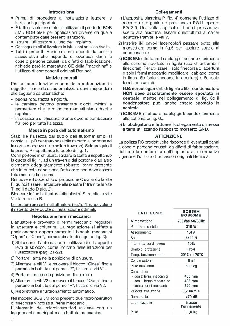
Dichiarazione CE di conformità
Fabbricante: Automatismi Benincà SpA.Indirizzo: Via Capitello, 45 - 36066 Sandrigo (VI) - Italia
Dichiara che: l’automazione per cancelli battenti modelli BOB50M / BOB50ME.
è conforme alle condizioni delle seguenti altre Direttive CE:
- DIRETTIVA 2004/108/CE DEL PARLAMENTO EUROPEO E DEL CONSIGLIO del 15 dicembre 2004 concernente il ravvicinamento delle legislazioni degli Stati membri relative alla compatibilità elettromagnetica e che abroga la direttiva 89/336/CEE, secondo le seguenti norme armonizzate: EN 61000-6-2:2005, EN 61000-6-3:2007.
- DIRETTIVA 2006/95/CE DEL PARLAMENTO EUROPEO E DEL CONSIGLIO del 12 dicembre 2006 concernente il ravvicinamento delle legislazioni degli Stati membri relative al materiale elettrico destinato ad essere adoperato entro taluni limiti di tensione, secondo le seguenti norme armonizzate: EN 60335-1:2002 + A1:2004 + A11:2004 + A12:2006 + A2:2006 + A13:2008; EN 60335-1-103:2003.
Benincà Luigi, Responsabile legale.Sandrigo, 10/06/2010.
AVVERTENZEE' vietato l'utilizzo del prodotto per scopi o con moda-lità non previste nel presente manuale. Usi non corretti possono essere causa di danni al prodotto e mettere in pericolo persone e cose.
Si declina ogni responsabilità dall'inosservanza della buona tecnica nella costruzione dei cancelli, nonché dalle deformazioni che potrebbero verificarsi durante l'uso.
Conservare questo manuale per futuri utilizzi.
L'installazione deve essere effettuata da personale qua-lificato nel pieno rispetto delle normative vigenti.
I materiali dell'imballaggio non devono essere lasciati alla portata dei bambini in quanto fonte di potenziale peri-colo. Non disperdere nell'ambiente i materiali di imballo, ma separare le varie tipologie (es. cartone, polistirolo) e smaltirle secondo le normative locali.
L’installatore deve fornire tutte le informazioni relative al funzionamento automatico, manuale e di emergenza dell'automazione, e consegnare all’utilizzatore dell’im-pianto le istruzioni d’uso.
•Prevedere sulla rete di alimentazione un inter-ruttore/sezionatore onnipolare con distanza d’apertura dei contatti uguale o superiore a 3 mm.
Verificare che a monte dell’impianto elettrico vi sia un interrut-tore differenziale e una protezione di sovracorrente adeguati. Alcune tipologie di installazione richiedono il collegamen-to dell'anta ad un impianto di messa a terra rispondente alle vigenti norme di sicurezza.Durante gli interventi di installazione, manutenzione e riparazione, togliere l’alimentazione prima di accedere alle parti elettriche.
Le descrizioni e le illustrazioni presenti in questo manuale non sono impegnative. Lasciando inalterate le caratte-ristiche essenziali del prodotto il fabbricante si riserva il diritto di apportare qualsiasi modifica di carattere tecnico, costruttivo o commerciale senza impegnarsi ad aggior-nare la presente pubblicazione.
10
Introduzione• Prima di procedere all’installazione leggere le
istruzioni qui riportate.• ÈfattodivietoassolutodiutilizzareilprodottoBOB
5M / BOB 5ME per applicazioni diverse da quelle contemplate dalle presenti istruzioni.
• Istruirel’utilizzatoreall’usodell’impianto.• Consegnare all’utilizzatore le istruzioni ad esso rivolte.• Tutti i prodotti Benincà sono coperti da polizza
assicurativa che risponde di eventuali danni a cose o persone causati da difetti di fabbricazione, richiede però la marcatura CE della ”macchina” e l’utilizzo di componenti originali Benincà.
Notizie generaliPer un buon funzionamento delle automazioni in oggetto, il cancello da automatizzare dovrà rispondere alle seguenti caratteristiche:- buona robustezza e rigidità.- le cerniere devono presentare giochi minimi e
permettere che le manovre manuali siano dolci e regolari.
- in posizione di chiusura le ante devono combaciare fra loro per tutta l’altezza.
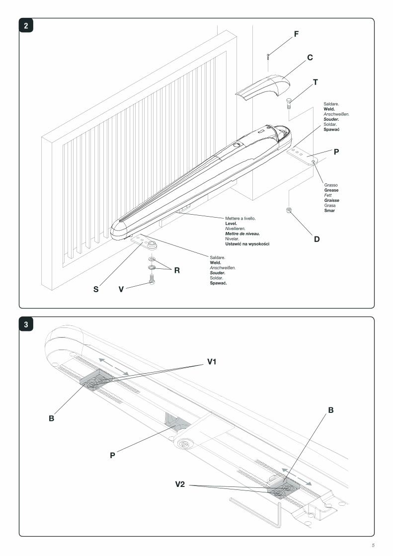
Messa in posa dell’automatismoStabilire l’altezza dal suolo dell’automatismo (si consiglia il più centrato possibile rispetto al portone ed in corrispondenza di un solido traverso). Saldare quindi la piastra P rispettando le quote di fig. 1.Con il portone in chiusura, saldare la staffa S rispettando la quota di fig. 1, ad un traverso del portone o ad altro elemento adeguatamente robusto; tener presente che in questa condizione l’attuatore non deve essere totalmente a fine corsa.Rimuovere il coperchio di protezione C svitando la vite F, quindi fissare l’attuatore alla piastra P tramite la vite T, ed il dado D (fig. 2).Bloccare infine l’attuatore alla piastra S tramite la vite V e la rondella R.Le forature presenti nell’attuatore (fig.1a-1b), agevolano il rispetto delle quote di installazione ottimali.
Regolazione fermi meccaniciL’attuatore è provvisto di fermi meccanici regolabili in apertura e chiusura. La regolazione si effettua posizionando opportunamente i blocchi meccanici “Open” e “Close”, come indicato di seguito (fig. 3):1) Sbloccare l’automazione, utilizzando l’apposita
leva di sblocco, come indicato nelle istruzioni per l’utilizzatore (pag. 21-22).
2) Portare l’anta nella posizione di chiusura.3) Allentare le viti V1 e muovere il blocco “Close” fino a
portarlo in battuta sul perno “P”, fissare le viti V1.4) Portare l’anta nella posizione di apertura.5) Allentare le viti V2 e muovere il blocco “Open” fino a
portarlo in battuta sul perno “P”, fissare le viti V2.6) Rispristinare il funzionamento automatico.
Nel modello BOB 5M sono presenti due microinterruttori di finecorsa vincolati ai fermi meccanici.L’intervento dei microinterruttori avviene con un leggero anticipo rispetto alla battuta meccanica.
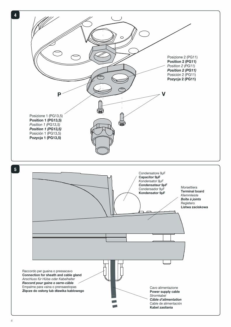
Collegamenti1) L’apposita piastrina P (fig. 4) consente l’utilizzo di
raccordo per guaina o pressacavo PG11 oppure PG13,5. Una volta applicato il tipo di pressacavo scelto alla piastrina, fissare quest’ultima al carter riduttore tramite le viti V.
2) Inserire il/i cavo/i facendolo/i passare sotto alla morsettiera come in fig.5 per lasciare spazio al condensatore.
3) BOB 5M: effettuare il cablaggio facendo riferimento allo schema riportato in fig.6a (uso di entrambi i finecorsa). Per utilizzare il solo finecorsa di apertura o solo i fermi meccanici modificare i cablaggi come in figura 6b (solo finecorsa in apertura) o 6c (solo fermi meccanici).
N.B: nei collegamenti di fig. 6a e 6b il condensatore NON deve assolutamente essere spostato in centrale, mentre nel collegamento di fig. 6c il condensatore puo’ anche essere spostato in centrale.
4) BOB 5ME: effettuare il cablaggio facendo riferimento allo schema di fig. 6d.
5) E’ obbligatorio effettuare il collegamento di messa a terra utilizzando l’apposito morsetto GND.
ATTENZIONELa polizza RC prodotti, che risponde di eventuali danni a cose o persone causati da difetti di fabbricazione, richiede la conformità dell’impianto alla normativa vigente e l’utilizzo di accessori originali Benincà.
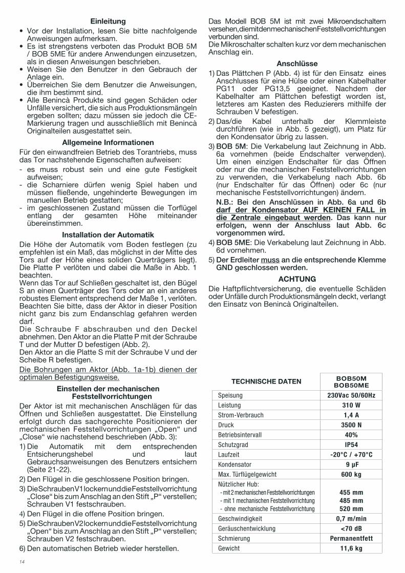
DATI TECNICI BOB50MBOB50ME
Alimentazione 230Vac 50/60HzPotenza assorbita 310 WAssorbimento 1,4 ASpinta 3500 NIntermittenza di lavoro 40%Grado di protezione IP54Temp. funzionamento -20°C / +70°CCondensatore 9 μFPeso max. anta 600 kgCorsa utile:- con 2 fermi meccanici- con 1 fermo meccanico- senza fermi meccanici
455 mm485 mm520 mm
Velocità traslazione 0,7 m/minRumorosità <70 dBLubrificazione Grasso
PermanentePeso 11,6 kg
11
WARNINGThe product shall not be used for purposes or in ways other than those for which the product is intended for and as described in this manual. Incorrect uses can damage the product and cause injuries and damages.
The company shall not be deemed responsible for the non-compliance with a good manufacture technique of gates as well as for any deformation, which might occur during use.
Keep this manual for further use.
Qualified personnel, in compliance with regulations in force, shall install the system.
Packaging must be kept out of reach of children, as it can be hazardous. For disposal, packaging must be divided the various types of waste (e.g. carton board, polystyrene) in compliance with regulations in force.
The installer must supply all information on the automatic, manual and emergency operation of the automatic sy-stem and supply the end user with instructions for use.
•An omnipolar switch/section switch with remote contact opening equal to, or higher than 3mm must be provided on the power supply mains..
Make sure that before wiring an adequate differential switch and an overcurrent protection is provided.
Pursuant to safety regulations in force, some types of in-stallation require that the gate connection be earthed.
During installation, maintenance and repair, cut off power supply before accessing to live parts.
Descriptions and figures in this manual are not binding. While leaving the essential characteristics of the product unchanged, the manufacturer reserves the right to modify the same under the technical, design or commercial point of view without necessarily update this manual.
EC Declaration of Conformity
Manufacturer: Automatismi Benincà SpA.Address: Via Capitello, 45 - 36066 Sandrigo (VI) - Italia
Herewith declares that: the operator for hinged gates model BOB50M / BOB50ME.
is complying with provisions set forth by the following other EC Directive:
- DIRECTIVE 2004/108/EC OF THE EUROPEAN PARLIAMENT AND OF THE COUNCIL of 15 December 2004, on the harmonisation of the laws of Member States relating to electromagnetic compatibility and which cancels Directive 89/336/EEC, according to the following harmonised regulations: EN 61000-6-2:2005, EN 61000-6-3:2007.
- DIRECTIVE 2006/95/EC OF THE EUROPEAN PARLIAMENT AND OF THE COUNCIL of 12 December 2006, on the harmonisation of the laws of Member States relating to electrical equipment designed for use with certain voltage limits, according to the following harmonised regulations: EN 60335-1:2002 + A1:2004 + A11:2004 + A12:2006 + A2:2006 + A13:2008; EN 60335-1-103:2003.
Benincà Luigi, Legal responsible.Sandrigo, 10/06/2010.

12
Introduction• Before installing the system, read the instruction
herein.• ItismandatorynottousetheBOB5M/BOB5ME
item for applications different from those indicated in the instructions herein.
• Supplytheenduserwithinstructionsforusingthissystem.
• The end user should receive special instruction manual.• AllBenincàitemsarecoveredbyaninsurancepolicy
for damages and injuries caused by manufacture faults. It is however required that the machine bear the CE marking and original Benincà parts be used.
General information To ensure a good operation of these automatic devices, the gate to be automated should meet the following requirements:- good strength and stiffness.- hinges should have a minimum backlash and allow
for smooth and regular manual operations.- when closed, the gate leaves should correctly
overlap for their entire height.
How to install the automatic system Calculate the height of the system from the ground (it is advisable to define a position as much centred as possible with respect to the main door and in correspondence with a strong cross girder). Weld the plate P, following measures in Fig. 1.With the door closed, weld bracket S to a cross beam of the main door or other element with equal strength, according to measures shown in Fig. 1. Keep in mind that, when carrying out this operation, the actuator should not be totally in a stroke end position.Remove the cover C by loosening the screw F. Then fix the actuator to the plate P by means of the screw T and the nut D (Fig. 2). Lock the actuator to plate S by means of screw V and washer R.The holes in the acturator (Fig. 1a-1b) help to keep to the optimum installation measures.
How to adjust the mechanical stoppersThe actuator is provided with adjustable mechanical stoppers in the opening and closing phases. The system is adjusted by suitably positioning the “Open” and “Close” mechanical locks, as shown hereunder (Fig.3):1) Unlock the automatic system by using the special
release lever, as shown in the instructions for the user (page 21-22).
2) Close the door/gate leaf.3) Loosen screws V1 and move the “Close” lock until
it reaches the pivot P, then tighten screws V1.4) Open the door/gate leaf.5) Loosen screws V2 and move the “Open” lock until
it reaches the pivot P, then tighten screws V2.6) Reset the automatic operating mode.In the BOB 5M version, two limit micro-switches are provided fixed to the mechanical stoppers.The micro-switches trigger slightly in advance with respect to the mechanical stop.
Connections
1) The special plate P (Fig. 4) allows for using a link for sheath or cable gland PG11, or PG13,5. Once the type of cable gland is applied to the plate, fix the latter to the adaptor cover by means of screws V.
2) Insert the cable, or cables, under the terminal board, as shown in Fig.5. This will leave enough space for the capacitor.
3) BOB 5M: carry out the wiring by referring to the wire diagram shown in Fig 6a (use both limit switches). In order to use either the opening limit switch or the mechanical stoppers, change wiring as shown in Fig. 6b (opening limit switch only) or 6c (mechanical stoppers only).
N.B: in wiring connections shown in Fig. 6a and 6b, the capacitor MUST NOT be connected to the control unit, while for wire connection shown in Fig. 6c, the capacitor can be connected to the control unit.
4) BOB 5ME: carry out the wiring by referring to wire diagram shown in Fig 6d.
5) It is mandatory to provide for ground by using the special GND terminal.
WARNINGThe insurance policy, which covers any damages or injuries caused by manufacture faults, requires that the installation comply with regulations in force and Benincà original accessories be used.
TECHNICAL DATA BOB50MBOB50ME
Power supply 230Vac 50/60HzAbsorbed rating 310 WAbsorbed current 1,4 AThrust 3500 NJogging 40%Protection degree IP54Operating temperature -20°C / +70°CCapacitor 9 μFDoor leaf max. weight 600 kgUseful stroke:- with 2 mechanical stoppers - with 1 mechanical stopper - without mechanical stoppers
455 mm485 mm520 mm
Translation speed 0,7 m/minNoise level <70 dBLubrication Permanent
greaseWeight 11,6 kg
13
HINWEISEDas Produkt darf nicht für andere Zwecke oder auf an-dere Weise verwendet werden, als in der vorliegenden Anleitung beschrieben. Ein ungeeigneter Gebrauch kann das Produkt beschädigen und eine Gefahr für Personen und Sachen darstellen.Wir übernehmen keinerlei Haftung für Schäden, die sich aus einer unsachgerechten Montage der Tore und aus daraus folgenden Verformungen ergeben können.Bewahren Sie dieses Handbuch für Nachschlagzwecke auf.Die Installation darf nur von qualifizierten Fachleuten laut den geltenden Vorschriften vorgenommen werden.Das Verpackungsmaterial fern von Kindern halten, da es eine potentielle Gefahr darstellt. Das Verpackung-smaterial nicht ins Freie werfen, sondern je nach Sorte (z.B. Pappe, Polystyrol) und laut den örtlich geltenden Vorschriften entsorgen.Der Installateur hat dem Benutzer alle Informationen über den automatischen, manuellen Betrieb sowie den Not-Betrieb der Automatik zusammen mit der Bedie-nungsanleitung zu liefern.
•Das Stromnetz muss mit einem allpoligen Schalter bzw. Trennschalter ausgestat-tet sein, dessen Kontakte einen Öffnung-
sabstand gleich oder größer als 3 aufweisen.. Kontrollieren, ob der elektrischen Anlage ein ge-eigneter Dif ferentialschalter und ein Überspan-n u n g s s c h u t z s c h a l t e r v o r g e s c h a l t e t s i n d . Einige Installationstypologien verlangen den Anschluss des Flügels an eine Erdungsanlage laut den geltenden Sicherheitsnormen.Während der Installation, der Wartung und der Reparatur, die Anlage stromlos machen bevor an den elektrischen Teilen gearbeitet wird.
Die in diesem Handbuch enthaltenen Beschreibungen und Abbildungen sind nicht verbindlich. Ausgenommen der Haupteigenschaften des Produkts, behält sich der Hersteller das Recht vor eventuelle technische, kon-struktive oder kommerzielle Änderungen vorzunehmen ohne dass er vorliegende Veröffentlichung auf den letzten Stand bringen muss.
EG-Konformitätserklärung
Hersteller: Automatismi Benincà SpA.Adresse: Via Capitello, 45 - 36066 Sandrigo (VI) - Italia
Wir erklären, dass: Antriebe für Drehflügeltore BOB50M / BOB50ME.
sie entspricht folgenden EG-Richtlinien:
- RICHTLINIE 2006/95/EG DES EUROPÄISCHEN PARLAMENTS UND DES RATES vom 12. Dezember 2006 zur Angleichung der Rechtsvorschriften der Mitgliedstaaten über die elektromagnetische Verträglichkeit und zur Aufhebung der Richtlinie 89/336/EWG, gemäß nachstehenden harmonisierten Normen: EN 61000-6-2:2005, EN 61000-6-3:2007.
- RICHTLINIE 2006/95/EG DES EUROPÄISCHEN PARLAMENTS UND DES RATES vom 12. Dezember 2006 zur Angleichung der Rechtsvorschriften der Mitgliedstaaten betreffend elektrische Betriebsmittel zur Verwendung innerhalb bestimmter Spannungsgrenzen, gemäß nachstehenden harmonisierten Normen: EN 60335-1:2002 + A1:2004 + A11:2004 + A12:2006 + A2:2006 + A13:2008; EN 60335-1-103:2003.
Benincà Luigi, RechtsvertreterSandrigo, 10/06/2010.
14
Einleitung• Vor der Installation, lesen Sie bitte nachfolgende
Anweisungen aufmerksam.• Es iststrengstensverbotendasProduktBOB5M
/ BOB 5ME für andere Anwendungen einzusetzen, als in diesen Anweisungen beschrieben.
• Weisen Sie den Benutzer in den Gebrauch derAnlage ein.
• Überreichen Sie demBenutzer die Anweisungen,die ihm bestimmt sind.
• Alle Benincà Produkte sind gegen Schäden oderUnfälle versichert, die sich aus Produktionsmängeln ergeben sollten; dazu müssen sie jedoch die CE-Markierung tragen und ausschließlich mit Benincà Originalteilen ausgestattet sein.
Allgemeine InformationenFür den einwandfreien Betrieb des Torantriebs, muss das Tor nachstehende Eigenschaften aufweisen:- es muss robust sein und eine gute Festigkeit
aufweisen;- die Scharniere dürfen wenig Spiel haben und
müssen fließende, ungehinderte Bewegungen im manuellen Betrieb gestatten;
- im geschlossenen Zustand müssen die Torflügel entlang der gesamten Höhe miteinander übereinstimmen.
Installation der AutomatikDie Höhe der Automatik vom Boden festlegen (zu empfehlen ist ein Maß, das möglichst in der Mitte des Tors auf der Höhe eines soliden Querträgers liegt). Die Platte P verlöten und dabei die Maße in Abb. 1 beachten.Wenn das Tor auf Schließen geschaltet ist, den Bügel S an einen Querträger des Tors oder an ein anderes robustes Element entsprechend der Maße 1, verlöten. Beachten Sie bitte, dass der Aktor in dieser Position nicht ganz bis zum Endanschlag gefahren werden darf.Die Schraube F abschrauben und den Deckel abnehmen. Den Aktor an die Platte P mit der Schraube T und der Mutter D befestigen (Abb. 2).Den Aktor an die Platte S mit der Schraube V und der Scheibe R befestigen.Die Bohrungen am Aktor (Abb. 1a-1b) dienen der optimalen Befestigungsweise.
Einstellen der mechanischen Feststellvorrichtungen
Der Aktor ist mit mechanischen Anschlägen für das Öffnen und Schließen ausgestattet. Die Einstellung erfolgt durch das sachgerechte Positionieren der mechanischen Feststellvorrichtungen „Open“ und „Close“ wie nachstehend beschrieben (Abb. 3):1) Die Automatik mit dem entsprechenden
Entsicherungshebel und laut Gebrauchsanweisungen des Benutzers entsichern (Seite 21-22).
2) Den Flügel in die geschlossene Position bringen.3) Die Schrauben V1 lockern und die Feststellvorrichtung
„Close“ bis zum Anschlag an den Stift „P“ verstellen; Schrauben V1 festschrauben.
4) Den Flügel in die offene Position bringen.5) Die Schrauben V2 lockern und die Feststellvorrichtung
„Open“ bis zum Anschlag an den Stift „P“ verstellen; Schrauben V2 festschrauben.
6) Den automatischen Betrieb wieder herstellen.
Das Modell BOB 5M ist mit zwei Mikroendschaltern versehen, die mit den mechanischen Feststellvorrichtungen verbunden sind.Die Mikroschalter schalten kurz vor dem mechanischen Anschlag ein.
Anschlüsse1) Das Plättchen P (Abb. 4) ist für den Einsatz eines
Anschlusses für eine Hülse oder einen Kabelhalter PG11 oder PG13,5 geeignet. Nachdem der Kabelhalter am Plättchen befestigt worden ist, letzteres am Kasten des Reduzierers mithilfe der Schrauben V befestigen.
2) Das/die Kabel unterhalb der Klemmleiste durchführen (wie in Abb. 5 gezeigt), um Platz für den Kondensator übrig zu lassen.
3) BOB 5M: Die Verkabelung laut Zeichnung in Abb. 6a vornehmen (beide Endschalter verwenden). Um einen einzigen Endschalter für das Öffnen oder nur die mechanischen Feststellvorrichtungen zu verwenden, die Verkabelung nach Abb. 6b (nur Endschalter für das Öffnen) oder 6c (nur mechanische Feststellvorrichtungen) ändern.
N.B.: Bei den Anschlüssen in Abb. 6a und 6b darf der Kondensator AUF KEINEN FALL in die Zentrale eingebaut werden. Das kann nur erfolgen, wenn der Anschluss laut Abb. 6c vorgenommen wird.
4) BOB 5ME: Die Verkabelung laut Zeichnung in Abb. 6d vornehmen.
5) Der Erdleiter muss an die entsprechende Klemme GND geschlossen werden.
ACHTUNGDie Haftpflichtversicherung, die eventuelle Schäden oder Unfälle durch Produktionsmängeln deckt, verlangt den Einsatz von Benincà Originalteilen.
TECHNISCHE DATEN BOB50MBOB50ME
Speisung 230Vac 50/60HzLeistung 310 WStrom-Verbrauch 1,4 ADruck 3500 NBetriebsintervall 40%Schutzgrad IP54Laufzeit -20°C / +70°CKondensator 9 μFMax. Türflügelgewicht 600 kgNützlicher Hub:- mit 2 mechanischen Feststellvorrichtungen- mit 1 mechanischen Feststellvorrichtung- ohne mechanische Feststellvorrichtung
455 mm485 mm520 mm
Geschwindigkeit 0,7 m/minGeräuschentwicklung <70 dBSchmierung PermanentfettGewicht 11,6 kg
15
REGLES DE SECURITE’Il est interdit d’utiliser ce produit pour l’utilisation du produit ou avec des finalités ou modalités non prévues par le présent manuel. Toute autre utilisation pourrait compromettre l’intégrité du produit et présenter un danger pour les personnes ou pour les biens.Le fabricant décline toute responsabilité en cas d’utilisation impropre ou d’inobservation de la bonne technique dans la construction des portails, ainsi que de toute déformation qui pourrait avoir lieu lors de son utilisation.Toujours conserver la notice pour toute autre consultation future.L’installation doit être faite uniquement par un personnel qualifié dans le respect total des normes en vigueur.Tenir à l’écart des enfants tous les matériaux d’emballage car ils représentent une source potentielle de danger. Ne pas di-sperser les matériaux d’emballage dans l’environnement, mais trier selon les différentes typologies (i.e. carton, polystyrène) et les traiter selon les normes locales.L’installateur doit fournir toutes les informations relatives au fonctionnement automatique, au déverrouillage d’urgence de l’automatisme, et livrer à l’utilisateur les modes d’emploi.
•Prévoir sur le réseau de l’alimentation un interrup-teur / sectionneur omnipolaire avec distance d’ou-verture des contacts égale ou supérieure à 3 mm..
Vérifier la présence en amont de l’installation électrique d’un interrupteur différentiel et d’une protection de surcourant adéquats.Certains types d’installation requièrent le branchement du vantail à une installation de mise à terre satisfaisant les normes de sécurité e vigueur.Avant toute intervention, d’installation, réparation et maintien, couper l’alimentation avant d’accéder aux parties électri-ques.
Les descriptions et les illustrations présentées dans ce manuel ne sont pas contraignantes. En laissant inaltérées les carac-téristiques essentielles du produit, le fabricant se réserve le droit d’apporter toute modification à caractère technique, de construction ou commerciale sans s’engager à revoir la cette publication.
Déclaration CE de conformité
Fabricant: Automatismi Benincà SpA.Adresse: Via Capitello, 45 - 36066 Sandrigo (VI) - Italia
Déclaire ci-apres que: l’automation pour portails ouvrants BOB50M / BOB50ME.
elle satisfait les conditions des autres Directives CE ci-dessous:
- DIRECTIVE 2004/108/CE DU PARLEMENT EUROPÉEN ET DU CONSEIL du 15 dècembre 2004 concernant le rapprochement des legislations des États membres relatives à la compatibilité électromagnétique et abrogeant la directive 89/336/CEE, selon les suivantes normes harmonisées: EN 61000-6-2:2005, EN 61000-6-3:2007.
- DIRECTIVE 2006/95/CE DU PARLEMENT EUROPÉEN ET DU CONSEIL du 12 décembre 2006 concernant le rapprochement des legislations des États membres relatives au materiel électrique destiné à être employé dans certaines limites de tension ,selon les suivantes normes harmonisées: EN 60335-1:2002 + A1:2004 + A11:2004 + A12:2006 + A2:2006 + A13:2008; EN 60335-1-103:2003.
Benincà Luigi, Responsable légal.Sandrigo, 10/06/2010.
16
Introduction• Avant de commencer toute installation lire les
instructions ci de suite.• Il est strictement interditd’utiliser leproduitBOB
5M / BOB 5ME pour toute application qui ne soit pas décrite dans ce mode d’emploi.
• Formerl’utilisateuràl’usagedel’installation.• Remettreàl’utilisateurlesinstructionsd’usage.• Tous les produits Benincà sont couverts par
une police d’assurance qui couvre d’éventuels dommages subis par objets ou personnes provoqués par des défauts de fabrication. Pourtant il faut qu’il y ait le marquage CE de la « machine » et l’utilisation de pièces et parties originales Benincà.
Renseignements en généralPour un bon fonctionnement des automations en objet, le portail à automatiser doit répondre aux caractéristiques suivantes:- bonne solidité et rigidité.- les charnières doivent présenter très peu de jeu à
fin que les manœuvres manuelles soient souples et régulières.
- en position de fermeture les vantaux doivent se joindre parfaitement sur toute la hauteur.
Installation de l’automatisme de portailDécider quelle sera la hauteur du sol désirée pour l’automatisme (on suggère de le centrer le plus possible par rapport au portail et en correspondance d’une barre solide). Par la suite souder la plaque P en respectant les côtes de la fig. 1.Avec le portail en fermeture, souder la bride S tout en respectant les côtes de la fig. 1, à une barre du portail ou à n’importe quel autre élément assez fort. Il faut toujours tenir compte que dans cette condition l’actuateur ne doit pas être complètement en fin de course.Ôter le couvercle de protection C en dévissant la vis F, par la suite fixer l’actuateur à la plaque P à l’aide de la vis T, et l’écrou D (fig. 2).En fin bloquer l’actuateur sur la plaque S à l’aide de la vis V et de la rondelle R.Les trous présents dans l’actuateur (fig.1a-1b), facilitent à respecter les côtes optimales d’installation.
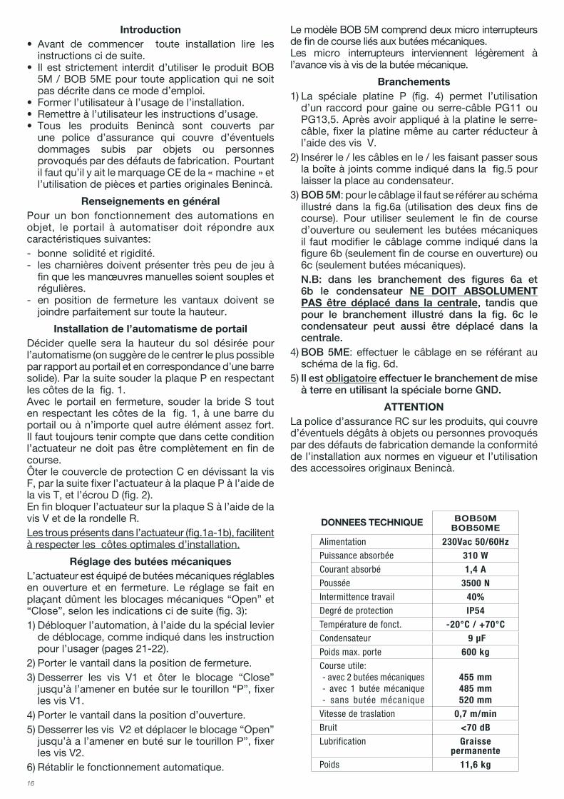
Réglage des butées mécaniquesL’actuateur est équipé de butées mécaniques réglables en ouverture et en fermeture. Le réglage se fait en plaçant dûment les blocages mécaniques “Open” et “Close”, selon les indications ci de suite (fig. 3):1) Débloquer l’automation, à l’aide du la spécial levier
de déblocage, comme indiqué dans les instruction pour l’usager (pages 21-22).
2) Porter le vantail dans la position de fermeture.3) Desserrer les vis V1 et ôter le blocage “Close”
jusqu’à l’amener en butée sur le tourillon “P”, fixer les vis V1.
4) Porter le vantail dans la position d’ouverture.5) Desserrer les vis V2 et déplacer le blocage “Open”
jusqu’à a l’amener en buté sur le tourillon P”, fixer les vis V2.
6) Rétablir le fonctionnement automatique.
Le modèle BOB 5M comprend deux micro interrupteurs de fin de course liés aux butées mécaniques.Les micro interrupteurs interviennent légèrement à l’avance vis à vis de la butée mécanique.
Branchements1) La spéciale platine P (fig. 4) permet l’utilisation
d’un raccord pour gaine ou serre-câble PG11 ou PG13,5. Après avoir appliqué à la platine le serre-câble, fixer la platine même au carter réducteur à l’aide des vis V.
2) Insérer le / les câbles en le / les faisant passer sous la boîte à joints comme indiqué dans la fig.5 pour laisser la place au condensateur.
3) BOB 5M: pour le câblage il faut se référer au schéma illustré dans la fig.6a (utilisation des deux fins de course). Pour utiliser seulement le fin de course d’ouverture ou seulement les butées mécaniques il faut modifier le câblage comme indiqué dans la figure 6b (seulement fin de course en ouverture) ou 6c (seulement butées mécaniques).
N.B: dans les branchement des figures 6a et 6b le condensateur NE DOIT ABSOLUMENT PAS être déplacé dans la centrale, tandis que pour le branchement illustré dans la fig. 6c le condensateur peut aussi être déplacé dans la centrale.
4) BOB 5ME: effectuer le câblage en se référant au schéma de la fig. 6d.
5) Il est obligatoire effectuer le branchement de mise à terre en utilisant la spéciale borne GND.
ATTENTIONLa police d’assurance RC sur les produits, qui couvre d’éventuels dégâts à objets ou personnes provoqués par des défauts de fabrication demande la conformité de l’installation aux normes en vigueur et l’utilisation des accessoires originaux Benincà.
DONNEES TECHNIQUE BOB50MBOB50ME
Alimentation 230Vac 50/60HzPuissance absorbée 310 WCourant absorbé 1,4 APoussée 3500 NIntermittence travail 40%Degré de protection IP54Température de fonct. -20°C / +70°CCondensateur 9 μFPoids max. porte 600 kgCourse utile:- avec 2 butées mécaniques- avec 1 butée mécanique- sans butée mécanique
455 mm485 mm520 mm
Vitesse de traslation 0,7 m/minBruit <70 dBLubrification Graisse
permanentePoids 11,6 kg

17
ADVERTENCIASEstá prohibido utilizar el producto para finalidades o con modalidades no previstas en el presente manual. Usos incorrectos pueden causar daños al producto y poner en peligro personas y cosas.Se rehúsa cualquier responsabilidad en caso de incum-plimiento de la buena técnica en la construcción de las cancelas, así como en cuanto a las deformaciones que pudieran producirse durante el uso.Guardar este manual para futuras consultas. La instala-ción debe ser efectuada por personal cualificado respe-tando plenamente las normas vigentes.Los elementos del embalaje no se deben dejar al alcance de los niños ya que son potenciales fuentes de peligro. No tirar al medio ambiente los elementos del embalaje, sino que se deben separar según los varios tipos (por ej. cartón, poliestireno) y evacuarlos de conformidad con las normas locales.El instalador debe proporcionar todas las informaciones relativas al funcionamiento automático, manual y de emergencia de la automatización y entregar al usuario del equipo las instrucciones de uso.
•Prever en la red de alimentación un interruptor/cortacircuitos omnipolar con distancia de aper-tura de los contactos igual o mayor que 3 mm.
Comprobar que entre el aparato y la red eléctrica general haya un interruptor diferencial y una pro-tección contra sobrecorriente adecuados. Algunos tipos de instalación requieren que se conecte la hoja con una instalación de puesta a tierra conforme a las vigentes normas de seguridad.Durante las operaciones de instalación, mantenimiento y reparación, cortar la alimentación antes de acceder a las partes eléctricas.
Las descripciones y las ilustraciones presentadas en este manual no son vinculantes. Sin cambiar las característi-cas esenciales del producto, el fabricante se reserva el derecho de aportar cualquier modificación de carácter técnico, constructivo o comercial sin obligación de ac-tualizar la presente publicación.
Declaración CE de conformidad
Fabricante: Automatismi Benincà SpA.Dirección: Via Capitello, 45 - 36066 Sandrigo (VI) - Italia
Declara que: la automatización para cancelas de batiente BOB50M / BOB50ME.
cumple las condiciones de las siguientes otras Directivas CE:
- DIRECTIVA 2004/108/CE DEL PARLAMENTO EUROPEO Y DEL CONSEJO del 15 de diciembre de 2004 sobre la aproximación de las legislaciones de los Estados miembros con relación a la compatibilidad electromagnética y que abroga la Directiva 89/336(CEE, según las siguientes normas armonizadas: EN 61000-6-2:2005, EN 61000-6-3:2007.
- DIRECTIVA 2006/95/CE DEL PARLAMENTO EUROPEO Y DEL CONSEJO del 12 de diciembre de 2006 sobre la aproximación de las legislaciones de los Estados miembros con relación al material eléctrico destinado a ser utilizado dentro de determinados límites de tensión, según las siguientes normas armonizadas: EN 60335-1:2002 + A1:2004 + A11:2004 + A12:2006 + A2:2006 + A13:2008; EN 60335-1-103:2003.
Benincà Luigi, Responsable legal.Sandrigo, 10/06/2010.
18
Introducción• Antes de proceder con la instalación leer las
instrucciones aquí presentadas.• Se prohíbe terminantemente utilizar el producto
BOB 5M / BOB 5ME para aplicaciones distintas de aquellas previstas en estas instrucciones.
• Enseñaralusuarioausarlainstalación.• Entregar al usuario las instrucciones destinadas a él.• Todos los productos Benincà están amparados
por una póliza de seguros que responde de eventuales daños a cosas o personas causados por defectos de fabricación, pero exige el marcado CE de la ”máquina” y la utilización de componentes originales Benincà.
Noticias generalesPara un buen funcionamiento de las automatizaciones consideradas, la cancela a automatizar deberá tener las siguientes características:- buena robustez y rigidez.- las charnelas deben presentar holguras muy
reducidas y permitir que las maniobra manuales sean suaves y uniformes.
- en posición de cierre, las hojas deben encajar entre ellas a lo largo de toda su altura.
Emplazamiento del automatismoDeterminar la altura del automatismo respecto al suelo (se aconseja lo más central posible con respecto a la cancela y en correspondencia de un travesaño robusto). Seguidamente soldar la placa P respetando las cotas de la fig. 1.Con la cancela en cierre, soldar el soporte S, respetando la cota de la fig. 1, a un travesaño de la cancela o a otro elemento adecuadamente robusto; tener presente que en esta condición el accionador no tiene que estar completamente al final de carrera.Quitar la tapa protectora C desenroscando el tornillo F y seguidamente fijar el accionador a la placa P mediante el tornillo T y la tuerca D (fig. 2).Por último afirmar el accionador a la placa S mediante el tornillo V y la arandela R.Los taladros presentes en el accionador (fig.1a-1b), facilitan el respeto de las cotas óptimas de instalación.
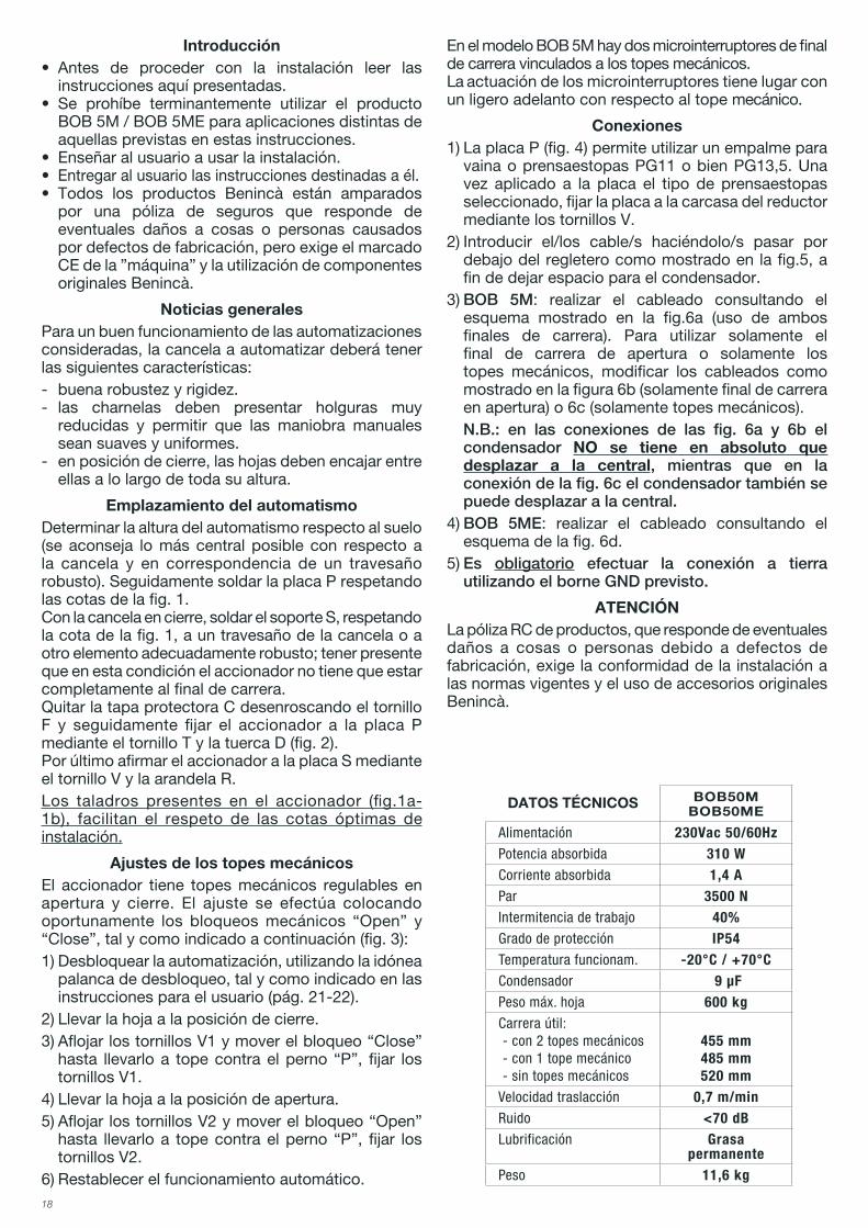
Ajustes de los topes mecánicosEl accionador tiene topes mecánicos regulables en apertura y cierre. El ajuste se efectúa colocando oportunamente los bloqueos mecánicos “Open” y “Close”, tal y como indicado a continuación (fig. 3):1) Desbloquear la automatización, utilizando la idónea
palanca de desbloqueo, tal y como indicado en las instrucciones para el usuario (pág. 21-22).
2) Llevar la hoja a la posición de cierre.3) Aflojar los tornillos V1 y mover el bloqueo “Close”
hasta llevarlo a tope contra el perno “P”, fijar los tornillos V1.
4) Llevar la hoja a la posición de apertura.5) Aflojar los tornillos V2 y mover el bloqueo “Open”
hasta llevarlo a tope contra el perno “P”, fijar los tornillos V2.
6) Restablecer el funcionamiento automático.
En el modelo BOB 5M hay dos microinterruptores de final de carrera vinculados a los topes mecánicos.La actuación de los microinterruptores tiene lugar con un ligero adelanto con respecto al tope mecánico.
Conexiones1) La placa P (fig. 4) permite utilizar un empalme para
vaina o prensaestopas PG11 o bien PG13,5. Una vez aplicado a la placa el tipo de prensaestopas seleccionado, fijar la placa a la carcasa del reductor mediante los tornillos V.
2) Introducir el/los cable/s haciéndolo/s pasar por debajo del regletero como mostrado en la fig.5, a fin de dejar espacio para el condensador.
3) BOB 5M: realizar el cableado consultando el esquema mostrado en la fig.6a (uso de ambos finales de carrera). Para utilizar solamente el final de carrera de apertura o solamente los topes mecánicos, modificar los cableados como mostrado en la figura 6b (solamente final de carrera en apertura) o 6c (solamente topes mecánicos).
N.B.: en las conexiones de las fig. 6a y 6b el condensador NO se tiene en absoluto que desplazar a la central, mientras que en la conexión de la fig. 6c el condensador también se puede desplazar a la central.
4) BOB 5ME: realizar el cableado consultando el esquema de la fig. 6d.
5) Es obligatorio efectuar la conexión a tierra utilizando el borne GND previsto.
ATENCIÓNLa póliza RC de productos, que responde de eventuales daños a cosas o personas debido a defectos de fabricación, exige la conformidad de la instalación a las normas vigentes y el uso de accesorios originales Benincà.
DATOS TÉCNICOS BOB50MBOB50ME
Alimentación 230Vac 50/60HzPotencia absorbida 310 WCorriente absorbida 1,4 APar 3500 NIntermitencia de trabajo 40%Grado de protección IP54Temperatura funcionam. -20°C / +70°CCondensador 9 μFPeso máx. hoja 600 kgCarrera útil:- con 2 topes mecánicos- con 1 tope mecánico- sin topes mecánicos
455 mm485 mm520 mm
Velocidad traslacción 0,7 m/minRuido <70 dBLubrificación Grasa
permanentePeso 11,6 kg
19
OSTRZEŻENIAZabrania się używania produktu do celów i w sposób inny niż przewidziane w niniejszym podręczniku. Nieprawidło-we używanie może spowodować uszkodzenie produktu i stanowić zagrożenie dla osób i rzeczy. Nie bierze się na siebie żadnej odpowiedzialności za nieprzestrzeganie reguł dobrej techniki budowlanej przy realizacji bram, a także w przypadku odkształceń, które mogłyby powstać w trakcie użytkowania. Przechowywać niniejszy podręcznik do przyszłego użytku.Instalacja musi być wykonana przez wykwalifikowany personel z zachowaniem wszelkich obowiązujących przepisów prawnych.Nie można pozostawiać opakowania w miejscach do-stępnych dla dieci, ponieważ może to być niebezpieczne. Nie pozostawiać opakowania w środowisku, tylko po-dzielić na poszczególne kategorie odpadów (n.p. karton, polistyrol) i zlikwidować je zgodnie z obowiązującymi przepisami miejscowymi. Instalator zobowiązany jest do udzielenia wszelkich in-formacji dotyczących działania w trybie automatycznym, ręcznym i w przypadku zaistnienia stanu alarmowego automatyzacji i wręczyć użytkownikowi instalacji instruk-cję użytkowania.
•Należy przewidzieć w sieci wyłącznik/odłącznik sek-cyjny wielobiegunowy, gdzie odległość rozwarcia między stykami będzie równa lub większa 3 mm..
Sprawdzić, czy przed instalacją elektryczną jest odpo-wiedni wyłącznik dyferencjalny i zabezpieczenie przed przetężeniem.Niektóre typologie instalacji wymagają podłączenia skrzy-dła do uziemienia zgodnego z obowiązującymi normami bezpieczeństwa.Podczas prac instalacyjnych, konserwacji i naprawy, przed przystąpieniem do prac na częściach elektrycznych należy odciąć zasilanie.
Opisy i ilustracje znajdujące się w niniejszym podręczniku podane są wyłącznie przykładowo. Pozostawiając nie-zmienione istotne charakterystyki techniczne produktu, producent zastrzega sobie prawo do wprowadzania każdej zmiany o charakterze technicznym, konstrukcyj-nym lub handlowym, bez konieczności modyfikowania niniejszej publikacji.
Deklaracja zgodności z normą CE
Producent: Automatismi Benincà SpA.Adres: Via Capitello, 45 - 36066 Sandrigo (VI) - Italia
Oświadcza że: Automatyzm do bram uchylnych model BOB50M / BOB50ME.
zgodne jest z wymogami innych, niżej podanych Dyrektyw CE:
- DYREKTYWY 2004/108/WE RADY PARLAMENTU EUROPEJSKIEGO z dnia 15 grudnia 2004 w sprawie zbliżania ustawodawstwa państw członkowskich w zakresie kompatybilności elektromagnetycznej i anulującej postanowienia Dyrektywy 89/336/EWG, zgodnie z następującymi normami zharmonizowanymi: EN 61000-6-2:2005, EN 61000-6-3:2007.
- DYREKTYWY 2006/95/WE RADY PARLAMENTU EUROPEJSKIEGO z dnia 12 grudnia 2006 w sprawie zbliżania ustawodawstwa państw członkowskich w zakresie sprzętu elektrycznego przeznaczonego do użytku w ramach wyznaczonych wartości napięcia, zgodnie z następującymi normami zharmonizowanymi: EN 60335-1:2002 + A1:2004 + A11:2004 + A12:2006 + A2:2006 + A13:2008; EN 60335-1-103:2003.
Benincà Luigi, Odpowiedzialny za kwestie prawne.Sandrigo, 10/06/2010.
20
Wprowadzenie• Przedprzystąpieniemdomontażunależyzapoznać
się z treścią podanych niżej instrukcji.• Surowo zabrania się stosowania produktu BOB
5M / BOB 5ME do celów innych od podanych w niniejszej instrukcji.
• Przeszkolić użytkownika w zakresie obsługiurządzenia.
• Wręczyć użytkownikowi instrukcje dla niegoprzeznaczone.
• Wszystkie produkty Benincà są objęte polisąubezpieczeniową dotyczącą ewentualnych szkód w stosunku do mienia lub osób wynikających z wad fabrycznych, aby polisa była ważna maszyna powinna posiadać oznakowanie CE oraz należy stosować oryginalne części zamienne Benincà.
Ogólne uwagiW celu prawidłowego funkcjonowania niniejszego mechanizmu, brama do której ma być wbudowany powinna spełniać następujące wymogi:- dobra wytrzymałość i sztywność.- zawiasy powinny mieć minimalny luz i umożliwiać
łagodne i prawidłowe wykonanie czynności ręcznych.
- w pozycji zamknięcia skrzydła powinny stykać się ze sobą na całej długości.
Instalacja urządzeniaUstalić wysokość urządzenia od podłoża (zaleca się zachowanie możliwie najbardziej środkowej pozycji w odniesieniu do bramy i w miejscu solidnej belki). Następnie, przyspawać płytę P przestrzegając nastaw podanych na rys. 1.Przy bramie w położeniu zamknięcia, przyspawać wspornik S przestrzegając nastawy podanej na rys. 1, do belki bramy lub do innego odpowiednio wytrzymałego elementu; pamiętać o tym, że w tych warunkach napęd nie powinien znajdować się w pozycji całkowicie na końcu toru.Usunąć pokrywę ochronną C odkręcając śrubę F, następnie przymocować napęd do płyty P za pośrednictwem śruby T i nakrętki D (rys. 2).Na końcu dobrze przymocować napęd do płyty S za pośrednictwem śruby V i podkładki R.Otwory znajdujące się na napędzie (rys.1a-1b), ułatwiają przestrzeganie optymalnych nastaw instalacyjnych.
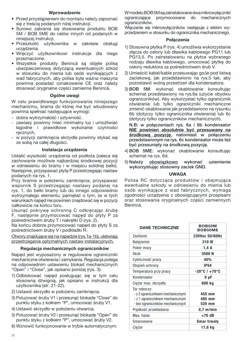
Regulacja mechanicznych ogranicznikówNapęd jest wyposażony w regulowane ograniczniki mechaniczne otwierania i zamykania. Regulacja polega na odpowiednim ustawieniu blokad mechanicznych “Open” i “Close”, jak opisano poniżej (rys. 3):1) Odblokować napęd posługując się w tym celu
stosowną dźwignią, jak opisano w instrukcji dla użytkownika (str. 21-22).
2) Ustawić skrzydło w położeniu zamknięcia.3) Poluzować śruby V1 i przesunąć blokadę “Close” do
punktu styku z kołkiem “P”, umocować śruby V1.4) Ustawić skrzydło w położeniu otwarcia.5) Poluzować śruby V2 i przesunąć blokadę “Open” do
punktu styku z kołkiem “P”, umocować śruby V2.6) Wznowić funkcjonowanie w trybie automatycznym.
W modelu BOB 5M są zainstalowane dwa mikrowyłączniki ograniczające przymocowane do mechanicznych ograniczników.Włączenie się mikrowyłączników następuje z lekkim wy-przedzeniem w stosunku do ogranicznika mechanicznego.
Połączenia
1) Stosowna płytka P (rys. 4) umożliwia wykorzystanie złącza do osłony lub dławika kablowego PG11 lub PG13,5. Po zainstalowaniu na płytce wybranego rodzaju dławika kablowego, umocować płytkę do osłony reduktora za pośrednictwem śrub V.
2) Umieścić kabel/kable przesuwając go/je pod listwą zaciskową, jak przedstawiono na rys.5 tak, aby pozostawić wolną przestrzeń dla kondensatora.
3) BOB 5M: wykonać okablowanie konsultując schemat przedstawiony na rys.6a (użycie obydwu ograniczników). Aby wykorzystać tylko ogranicznik otwierania lub tylko ograniczniki mechaniczne zmienić okablowanie jak przedstawiono na rysunku 6b (dotyczy tylko ogranicznika otwierania) lub 6c (dotyczy tylko ograniczników mechanicznych).
N.B: w połączeniach rys. 6a i 6b kondensator NIE powinien absolutnie być przesuwany na środkową pozycję, natomiast w połączeniu przedstawionym na rys. 6c kondensator może też być przesunięty na środkową pozycję.
4) BOB 5ME: wykonać okablowanie konsultując schemat na rys. 6d.
5) Należy obowiązkowo wykonać uziemienie wykorzystując stosowny zacisk GND.
UWAGAPolisa RC dotycząca produktów i obejmująca ewentualne szkody w odniesieniu do mienia lub osób wynikające z wad fabrycznych, wymaga zgodności urządzenia z obowiązującymi przepisami oraz stosowania oryginalnych części zamiennych Benincà.
DANE TECHNICZNE BOB50MBOB50ME
Zasilanie 230Vac 50/60HzNatężemie 310 WPobór mocy 1,4 ASkok 3500 NCykliczność pracy 40%Stopień ochrony IP54Temperatura przy pracy -20°C / +70°CKondensator 9 μFCiężar max. skrzydła 600 kgTor roboczy:- z 2 ogranicznikami mechanicznymi- z 1 ogranicznikiem mechanicznym- bez ograniczników mechanicznych
455 mm485 mm520 mm
Prędkość przekładania 0,7 m/minMax. halas <70 dBSmarowanie Smar trwałyCiężar 11,6 kg
21
Libro istruzioni per l’utilizzatoreUser’s handbook for the userHandbuch für den VerbraucherManuel d’instructions pour l’utilisateurLibro de instrucciones para el usuarioInstrukcja obsługi dla użytkownika
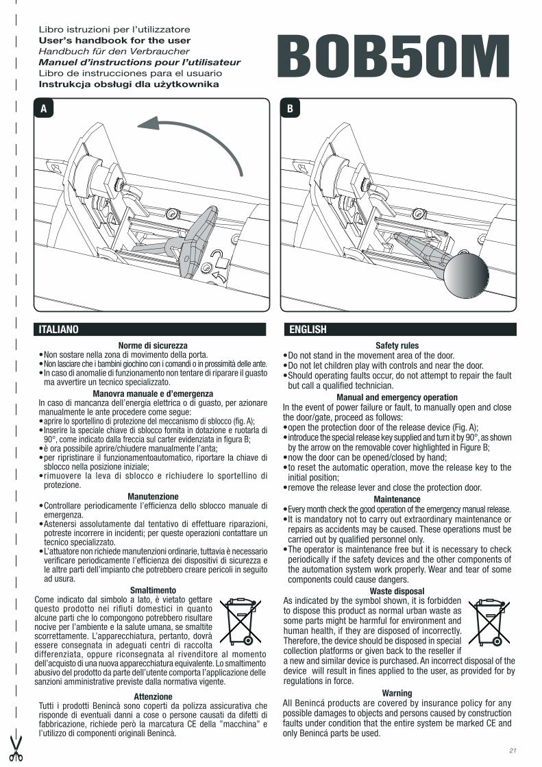
Norme di sicurezza•Nonsostarenellazonadimovimentodellaporta.•Non lasciare che i bambini giochino con i comandi o in prossimità delle ante.•Incasodianomaliedifunzionamentonontentarediriparareilguasto
ma avvertire un tecnico specializzato.Manovra manuale e d’emergenza
In caso di mancanza dell’energia elettrica o di guasto, per azionare manualmente le ante procedere come segue:•aprire lo sportellino di protezione del meccanismo di sblocco (fig. A);• Inserire la speciale chiave di sblocco fornita in dotazione e ruotarla di
90°, come indicato dalla freccia sul carter evidenziata in figura B;•èorapossibileaprire/chiuderemanualmentel’anta;•perripristinare il funzionamentoautomatico, riportare lachiavedi
sblocco nella posizione iniziale;•rimuovere la leva di sblocco e richiudere lo sportellino di
protezione.Manutenzione
•Controllare periodicamente l’efficienza dello sbloccomanuale diemergenza.
•Astenersi assolutamente dal tentativo di effettuare riparazioni,potreste incorrere in incidenti; per queste operazioni contattare un tecnico specializzato.
•L’attuatorenonrichiedemanutenzioniordinarie,tuttaviaènecessarioverificare periodicamente l’efficienza dei dispositivi di sicurezza e le altre parti dell’impianto che potrebbero creare pericoli in seguito ad usura.
Smaltimento
AttenzioneTutti i prodotti Benincà sono coperti da polizza assicurativa che risponde di eventuali danni a cose o persone causati da difetti di fabbricazione, richiede però la marcatura CE della ”macchina” e l’utilizzo di componenti originali Benincà.
Safety rules•Donotstandinthemovementareaofthedoor.•Donotletchildrenplaywithcontrolsandnearthedoor.•Shouldoperatingfaultsoccur,donotattempttorepairthefault
but call a qualified technician.Manual and emergency operation
In the event of power failure or fault, to manually open and close thedoor/gate,proceedasfollows:•opentheprotectiondoorofthereleasedevice(Fig.A);• introduce the special release key supplied and turn it by 90°, as shown
by the arrow on the removable cover highlighted in Figure B;•nowthedoorcanbeopened/closedbyhand;•toresettheautomaticoperation,movethereleasekeytothe
initial position;•removethereleaseleverandclosetheprotectiondoor.
Maintenance•Every month check the good operation of the emergency manual release.•Itismandatorynottocarryoutextraordinarymaintenanceor
repairs as accidents may be caused. These operations must be carried out by qualified personnel only.
•Theoperatorismaintenancefreebutitisnecessarytocheckperiodically if the safety devices and the other components of the automation system work properly. Wear and tear of some components could cause dangers.
Waste disposal
WarningAll Benincá products are covered by insurance policy for any possible damages to objects and persons caused by construction faults under condition that the entire system be marked CE and only Benincá parts be used.
ITALIANO ENGLISH
BOB50MA B
Come indicato dal simbolo a lato, è vietato gettarequesto prodotto nei rifiuti domestici in quanto alcune parti che lo compongono potrebbero risultare nocive per l’ambiente e la salute umana, se smaltite scorrettamente. L’apparecchiatura, pertanto, dovrà essere consegnata in adeguati centri di raccolta differenziata, oppure riconsegnata al rivenditore al momento dell’acquisto di una nuova apparecchiatura equivalente. Lo smaltimento abusivo del prodotto da parte dell’utente comporta l’applicazione delle sanzioni amministrative previste dalla normativa vigente.
As indicated by the symbol shown, it is forbidden to dispose this product as normal urban waste as some parts might be harmful for environment and human health, if they are disposed of incorrectly. Therefore, the device should be disposed in special collection platforms or given back to the reseller if a new and similar device is purchased. An incorrect disposal of the device will result in fines applied to the user, as provided for by regulations in force.

22
Sicherheitsvorschriften• NichtimÖffnungsbereichverweilen.• Kinder nicht mit den Steuerungen oder in der Nähe des Tores spielen lassen.• BeiFunktionsausfällennichtversuchen,denSchadenselberzubeheben,
sondern den Techniker rufen.Manuelle Notbedienung
Bei einem Stromausfall oder im Falle einer Störung, kann der Torflügel fol-gendermaßen manuell gesteuert werden:• DiekleineSchutztürdesEntsicherungsmechanismusöffnen(Abb.A)• Den speziellen Entsicherungsschlüssel (mitgeliefert) einstecken und um 90°
in die Pfeilrichtung drehen, die am Kasten angegeben ist (siehe Abb. B)• NunkannderTorflügelvonHandgeöffnetbzw.geschlossenwerden• UmdenAutomatikbetriebwiederherzustellen,denEntsicherungsschlüssel
zurück in die Ausgangsposition drehen• DenEntsicherungshebelentfernenunddieSchutztürwiederschließen.
Wartung• MonatlicheKontrolledermanuellenNotentriegelung• Es ist absolut untersagt, selbstständig Sonderwartung oder Reparaturen vorzu-
nehmen, da Unfälle die Folge sein können; wenden Sie sich an den Techniker.• DerAntriebbrauchtkeineordentlicheUnterhaltungaberesistperiodisch
notwendig die Leistungsfähigkeit der Sicherheitsvorrichtungen und die andere Teile des Anlages zu prüfen. Sie könnten durch Abnutzung Gefaht hervorbringen.
Entsorgung
AchtungAlle Produkte BENINCA’ wurden mit einem Versicherungsschein versehen, der alle eventuellen Schäden an Dingen oder Personen abdeckt, die durch Herstellungsdefekte hervorgerufen wurden, vorausgesetzt, das Gerät besitzt die Kennzeichnung EU und es wurden original BENINCA’ Einzelkomponenten verwendet.
Normes de sécurité• Nepasstationnerdanslazonedemouvementdelaporte.• Nelaissezpaslesenfantsjoueraveclescommandesouàproximitéde
la porte.• Encasd’anomaliesdefonctionnement,n’essayezpasderéparerlapanne
mais contactez un technicien spécialisé.Manœuvre manuelle et manœuvre d’émergence
En cas de d’interruption de courant ou de panne, pour entraîner manuellement les vantaux il faut procéder comme il suit:• ouvrirlacachedeprotectiondumécanismededéblocage(fig.A);• Insérerlaspécialeclédedéblocage,fournieavecl’équipement,etla
tournerde90°,commeindiquéparlaflèchesurlecarteretmiseenévidence dans la figure B;
• maintenantlevantailpeutêtreouvert/fermémanuellement;• pourrestaurerlefonctionnementautomatiqueramenerlaclédedéblocage
dans la position initiale;• ôterlelevierdedéblocageetrefermerlacachedeprotection.
Maintenance• Contrôlertouslesmoislebonétatdudéverrouillagemanueld’urgence.• Netenteraucuneréparationouinterventionquipourraits’avérerdange-
reuse. Contactez impérativement un technicien spécialisé pour ce type d’opération.
• L’operateurnedemandepasd’entretienparticuliermaisilfautvérifierpériodiquement l’efficacité des dispositifs de sécurité ainsi que les autres points de l’installation qui pourraient créer des risques dû à l’usure.
Démolition
AttentionTous les produits Benincà sont couverts par une police d’assurance qui répond d’éventuels préjudices corporels ou matériels provoqués à cause de défauts de fabrication, mais qui requiert toutefois le marquage CE de la “machine” etl’utilisationdepiècesderechanged’origineBenincà.
Normas de seguridad• Nopararseenlazonademovimientodelapuerta.• Nodejarquelosniñosjueguenconlosmandooenproximidaddelapuerta.• Encasodeanomalíasdefuncionamientonointentarrepararlaaveríasino
que avisar a un técnico especializado.Maniobra manual y de emergencia
Encasodefaltadecorrienteeléctricaoencasodeavería,paraaccionarmanualmente las hojas proceder como sigue:• abrirlatapaprotectoradelmecanismodedesbloqueo(fig.A);• Introducir la llave especial de desbloqueo suministrada y darle una vuelta
de 90°, como indicado por la flecha en la carcasa indicada en la figura B;• ahoraesposibleabrir/cerrarmanualmentelahoja;• pararestablecerelfuncionamientoautomático,ponerdenuevolallave
de desbloqueo en la posición inicial;• quitarlapalancadedesbloqueoycerrardenuevolatapaprotectora.
Mantenimiento• Controlar periodicamente la eficiencia del desbloqueo manual de emergencia.• Abstenerseabsolutamentedeintentarefectuarreparaciones,podránincurriren
accidentes; para estas operaciones contactar con un técnico especializado.• Eloperadornorequieremantenimientohabitual,noobstanteesnecesario
verificar periódicamente la eficiencia de los dispositivos de seguridad y las otras partes de la instalación que pudiesen crear peligros a causa del desgaste.
Eliminación de aguas sucias
AtenciónTodos los productos Benincà están cubiertos por una póliza de seguros que respondedeeventualesdañosapersonasocosas,causadospordefectosdefabricación, requiere sin embargo la marca CE de la ”máquina” y la utilización de componentes originales Benincà.
Normy bezpieczeństwa• Nieprzestawaćwpoludziałaniabramy.• Niepozwalaćabydziecimogłybawićsięurządzeniamisterowaniabramylub
przebywać w pobliżu skrzydeł bramy.• Wprzypadkustwierdzenianieprawidłowegodziałaniaurządzeniaautomatyzacji
nie należy próbować samemu jej naprawiać, tylko wezwać uprawnionego technika.
Zabieg ręczny i zabieg awaryjnyW przypadku braku dopływu energii elektrycznej lub awarii, w celu ręcznego uruchomienia skrzydeł postępować jak poniżej:• otworzyćdrzwiczkiosłonowemechanizmuodblokowania(rys.A);• Włożyćspecjalnykluczdoodblokowaniaznajdującysięnawyposażeniuiobrócić
go o 90°, jak wskazuje strzałka na osłonie uwidoczniona na rysunku B;• terazmożnaręcznieotworzyć/zamknąćskrzydło;• wceluwznowienia funkcjonowaniaw trybieautomatycznym,ponownie
ustawićkluczwpołożeniupoczątkowym;• usunąćdźwignięodblokowaniaizamknąćdrzwiczkiosłonowe.
Konserwacja• Sprawdzaćokresowoskutecznośćdziałaniaurządzeniaręcznegoodsprzęgla-
nia w sytuacji awaryjnej.• Wżadnymwypadkunienależypróbowaćnaprawiaćurządzenia,ponieważmogłoby
tobyćprzyczynąwypadków;wtymcelunależywezwaćuprawnionegotechnika.• Motoreduktorniewymagastałejkonserwacji,niemniejjednaknależyokresowo
sprawdzaćstandziałaniaurządzeńbezpieczeństwaorazinnychelementów,których zużycie mogłoby spowodować sytuacje niebezpieczne.
Demolowanie
Uwaga!WszystkieproduktyBenincàposiadająpolisęubezpieczeniowąoodpowiedzial-ności cywilnej za produkty na pokrycie ewentualnych szkód spowodowanych wadami produkcyjnymi poniesionych przez rzeczy lub osoby pod warunkiem, że urządzeniebędzieposiadałooznaczenieCEorazżestosowanebędąoryginalneczęści Benincà.
DEUTSCH
FRANÇAIS
ESPAŇOL
POLSKY
Comoindicadoporelsímbolodeallado,estáprohibidotiraresteproducto a la basura doméstica ya que algunas partes que lo componenpodríassernocivasparaelmedioambienteylasaludhuman si se eliminan de manera errada. Por lo tanto el aparato se deberá entregar a idóneos centro de recogida selectiva o bien se deberá devolver al revendedor en el momento de comprar un nuevo aparato equivalente. La eliminación ilegal del producto por parte del usuario conlleva la aplicación de las sanciones adminis-trativas previstas por las normas vigentes.
Das seitlich abgebildete Symbol weißt darauf hin, dass das Produkt nicht als Hausmüll entsorgt werden darf, da einige Bestandteile für die Umwelt und die menschliche Gesundheit gefährlich sind. Das Gerät muss daher zu einer zugelassenen Entsorgungsstelle gebracht oder einem Händler beim Kauf eines neuen Geräts zurückerstattet werden. Eine nicht ordnungsgemäße Entsorgung ist laut Gesetz strafbar.
Jakwskazujeznajdującysięoboksymbol,zabraniasięwyrzucanianiniejszegowyrobu razem z odpadami gospodarstw domowych, gdyż niektóre komponenty składowe mogłyby okazać się szkodliwe dla środowiska naturalnego i zdrowia ludzkiego,jeżeliniezostałybyprawidłowousunięte.Zużyteurządzeniepowinnobyć,zatem,dostarczonedoodpowiednichośrodkówzajmującychsięselektywnązbiórkąodpadów lubdosklepuwchwilizakupunowego, równoważnegourządzenia.Nielegalne usunięcie odpadów przez użytkownika powoduje zastosowanie sankcji administracyjnychprzewidzianychprzezobowiązująceprzepisy.
Comme indiqué par le symbole à coté, il est interdit de jeter ce produit danslesorduresménagèrescarlespartiesquilecomposentpourraientnuire à l’environnent et à la santé des hommes, si traitées et évacuées de manièreincorrecte.L’appareillagedevra,parconséquent,êtrelivrédansles spéciaux point de collecte et de triage, ou bien remis au revendeur lorsqu’on décide d’acheter un appareillage équivalent. L’évacuation abu-sive du produit de la part de l’usager comporte l’application de sanctions administratives comme prévu par les normes en vigueur.
23
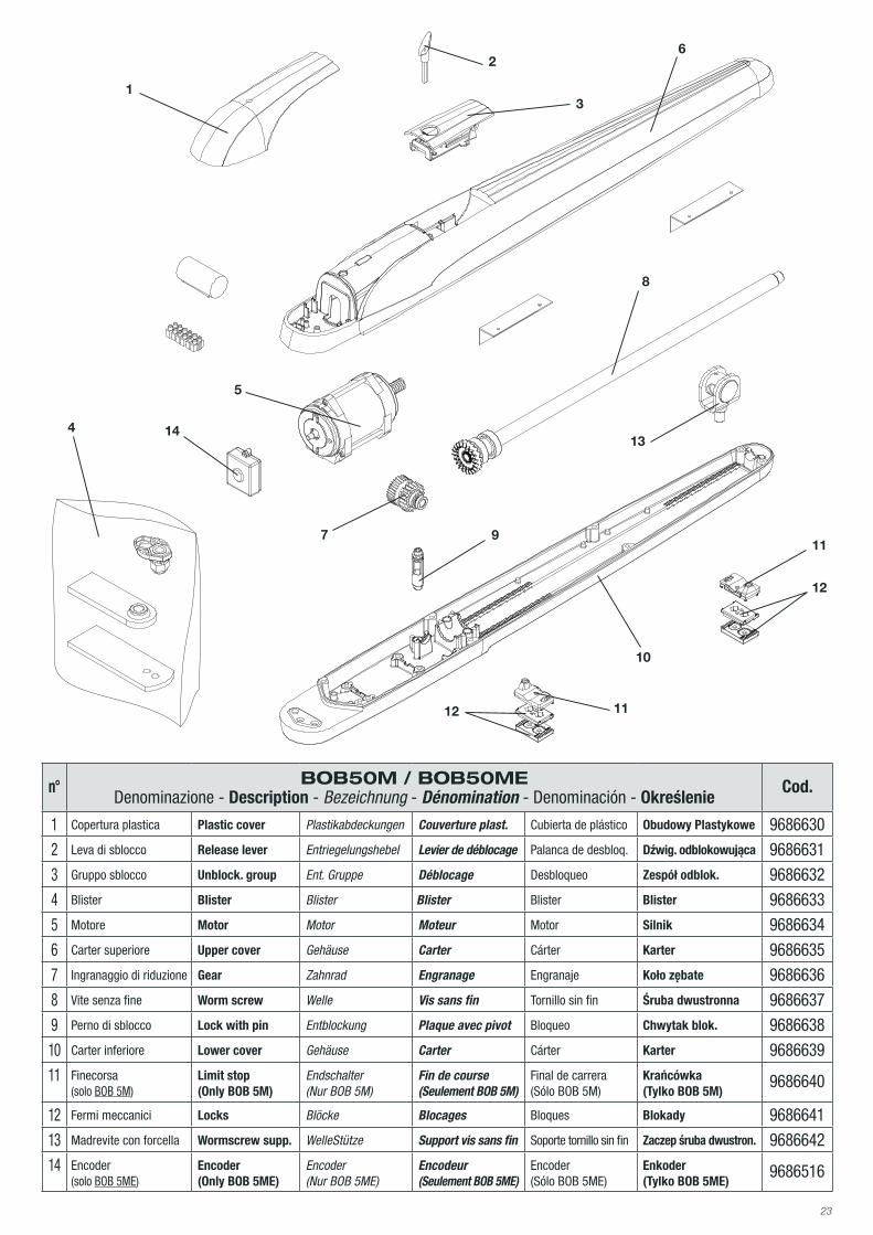
n° BOB50M / BOB50MEDenominazione - Description - Bezeichnung - Dénomination - Denominación - Określenie
Cod.
1 Copertura plastica Plastic cover Plastikabdeckungen Couverture plast. Cubierta de plástico Obudowy Plastykowe 96866302 Leva di sblocco Release lever Entriegelungshebel Levier de déblocage Palanca de desbloq. Dźwig. odblokowująca 96866313 Gruppo sblocco Unblock. group Ent. Gruppe Déblocage Desbloqueo Zespół odblok. 96866324 Blister Blister Blister Blister Blister Blister 96866335 Motore Motor Motor Moteur Motor Silnik 96866346 Carter superiore Upper cover Gehäuse Carter Cárter Karter 96866357 Ingranaggio di riduzione Gear Zahnrad Engranage Engranaje Koło zębate 96866368 Vite senza fine Worm screw Welle Vis sans fin Tornillo sin fin Śruba dwustronna 96866379 Perno di sblocco Lock with pin Entblockung Plaque avec pivot Bloqueo Chwytak blok. 968663810 Carter inferiore Lower cover Gehäuse Carter Cárter Karter 968663911 Finecorsa
(solo BOB 5M)Limit stop (Only BOB 5M)
Endschalter (Nur BOB 5M)
Fin de course (Seulement BOB 5M)
Final de carrera (Sólo BOB 5M)
Krańcówka (Tylko BOB 5M)
9686640
12 Fermi meccanici Locks Blöcke Blocages Bloques Blokady 968664113 Madrevite con forcella Wormscrew supp. WelleStütze Support vis sans fin Soporte tornillo sin fin Zaczep śruba dwustron. 968664214 Encoder
(solo BOB 5ME)Encoder (Only BOB 5ME)
Encoder (Nur BOB 5ME)
Encodeur (Seulement BOB 5ME)
Encoder (Sólo BOB 5ME)
Enkoder (Tylko BOB 5ME)
9686516
1
9
5
13
3
11
7
2
10
6
4 14
11
12
12
8

AUTOMATISMI BENINCÀ SpA - Via Capitello, 45 - 36066 Sandrigo (VI) - Tel. 0444 751030 r.a. - Fax 0444 759728