ISTRUZIONI DI MONTAGGIO PER MANIGLIONI ANTIPANICO … · antipanico, questo non preclude...
12
ISTRUZIONI DI MONTAGGIO PER MANIGLIONI ANTIPANICO SERIE 6200 ASSEMBLING INSTRUCTIONS FOR PANIC EXIT DEVICES SERIES 6200 INSTRUCTIONS DE MONTAGE POUR SERRURES ANTIPANIQUE SERIE 6200 N.B. Le caratteristiche di sicurezza per le persone di questo prodotto sono di importanza fondamentale ai fini della sua conformità alla EN 1125. Non sono ammesse modifiche di nessun tipo, fatta eccezione per quelle che sono descritte in queste istruzioni. RACCOMANDAZIONI PER L’INSTALLAZIONE E IL FISSAGGIO 1. Il maniglione è stato progettato per essere montato su porte in alluminio, se montato su porte non in alluminio potrebbe essere necessario usare sistemi di fissaggio diversi; 2. Il maniglione è destinato ad essere utilizzato soltanto su porte con ante di massa non maggiore di 300 Kg., altezza non maggiore di 3000 mm e larghezza non maggiore di 1300 mm. N.B.: nei kit deviatori sono forniti di serie componenti per porte fino a 2500 mm di altezza, per porte fino a 3000 mm utilizzare kit cod. 6032; 3. Non si consiglia il montaggio del maniglione su porte con interno alveolare; 4. Il maniglione non è destinato all’uso su porte che si aprono nei due sensi (va e vieni); 5. Se montato su una porta a vetri, il vetro deve essere temprato o stratificato; 6. Nella scelta del maniglione è importante scegliere la misura corretta della barra orizzontale, che deve essere installata in modo da coprire la massima larghezza utile della porta; 7. Nelle situazioni in cui lo spazio per l’uscita non è ampio, oppure la porta su cui deve essere installato il maniglione non è in grado di aprirsi oltre i 90°, sarebbe opportuno utilizzare un maniglione di categoria 2 (sporgenza standard); 8. Nel caso in cui i maniglioni antipanico debbano essere montati su una porta a due ante con montanti con battuta e dispositivi di chiusura auto- matica, si dovrebbe montare un dispositivo per il coordinamento delle porte conforme alla EN 1158, che assicuri la corretta sequenza di chiusura delle porte (particolarmente importante per le porte tagliafumo); 9. Nel caso si debba usare un chiudiporta, si deve fare attenzione a non rendere difficile l’uso della porta ai bambini, agli anziani e agli infermi; 10.Prima del montaggio del maniglione verificare che: - il telaio e la porta siano in buone condizioni e siano montati correttamente; - la porta abbia una rigidità tale da garantire sempre la sua apertura, anche in presenza di lievi distorsioni; - la porta non incontri ostacoli nel suo movimento; - le ante di una porta a due ante possano essere aperte contemporaneamente e le guarnizioni della porta non ne impediscano il corretto funzio- namento; 11.La barra orizzontale deve essere montata ad un’altezza compresa fra i 900 mm e i 1100 mm dal livello del pavimento finito, con i meccanismi in posizione di chiusura. Nel caso si sappia che la maggior parte degli occupanti il locale è rappresentata da bambini, si dovrebbe considerare di ridurre tale altezza; 12.Gli elementi di chiusura e le contropiastre devono essere fissati in modo che si innestino in maniera sicura. Assicurarsi che gli elementi di chiusu- ra, in posizione arretrata, non sporgano impedendo così alla porta di ruotare liberamente; 13.Per il bloccaggio della porta in posizione di chiusura non si devono montare ulteriori dispositivi (catene, sbarre, lucchetti, ecc.) oltre al maniglione antipanico, questo non preclude l’installazione di dispositivi di chiusura automatica; 14.Sulla superficie interna della porta, immediatamente sopra la barra orizzontale, dovrebbe essere apposto un cartello con la scritta “Per aprire spingere la barra”, oppure un pittogramma con area non minore di 8000 mm² e di colore bianco su sfondo verde; 15.In una porta a due ante con montanti con battuta, quando sono installati maniglioni antipanico su entrambe le ante, è indispensabile controllare che ciascuna anta si apra quando è azionato il relativo maniglione e anche che entrambe le ante si aprano liberamente quando i due maniglioni sono azionati contemporaneamente; 16.Durante il montaggio seguire scrupolosamente queste istruzioni che dovranno poi essere consegnate all’utilizzatore finale, richiamando la sua attenzione al paragrafo “MANUTENZIONE”; 17.Si raccomanda l’utilizzo di accessori e componenti originali; 18.Qualsiasi anomalia, reclamo, malfunzionamento o problema deve essere segnalato alla Omec Serrature S.p.A. I NOTE: The safety features of this product are essential to its compliance with EN 1125. No modification of any kind, other than those described in these instructions, is permitted. 1. The panic exit device is designed to be installed on aluminium doors, if assembled on non-alu doors, a different fixing could be necessary ; 2. Panic exit devices should normally be used on doorsets having a mass not heavier than 300 kg, a height not higher than 3000 mm and a width not larger than 1300 mm. NOTE: in the deviators kit components for doors of height up to 2500 mm are supplied, for doors of height up to 3000 mm use kit cod. 6032; 3. It is not recommended that panic exit device is fitted to hollow core doors ; 4. Panic exit devices are not intended for use on double action (double swing) doors ; 5. Where a panic exit device is designed to be fitted to a glazed door, it is essential that the glazing is tempered or laminated glass ; 6. In the choice of the panic exit device it is important to choose the right length of the horizontal bar, that should be installed so as to provide the maximum effective length ; 7. Category 2 (standard projection) panic exit devices should be used in situations where there is restricted width for escape, or where the doors to be fitted with the panic exit devices are not able to open beyond 90° ; 8. Where panic exit devices are to be fitted to double doorsets with rebated meeting stiles and self closing devices, a door coordinator device in accordance with EN 1158 should be fitted to ensure the correct closing sequence of the doors (this recommendation is particularly important with regard to smoke resisting door assemblies) ; 9. If a door closing device is to be used to return the door to the closed position, care should be taken not to impair the use of the doorway by the young, elderly and infirm ; GB RECOMMENDATIONS FOR INSTALLATION AND FIXING 1
Transcript of ISTRUZIONI DI MONTAGGIO PER MANIGLIONI ANTIPANICO … · antipanico, questo non preclude...
ISTRUZIONI DI MONTAGGIO PER MANIGLIONI ANTIPANICO SERIE 6200ASSEMBLING INSTRUCTIONS FOR PANIC EXIT DEVICES SERIES 6200INSTRUCTIONS DE MONTAGE POUR SERRURES ANTIPANIQUE SERIE 6200
N.B. Le caratteristiche di sicurezza per le persone di questo prodotto sono di importanza fondamentale ai fini della sua conformità alla EN 1125. Non sono ammesse modifiche di nessun tipo, fatta eccezione per quelle che sono descritte in queste istruzioni.
RACCOMANDAZIONI PER L’INSTALLAZIONE E IL FISSAGGIO
1. Il maniglione è stato progettato per essere montato su porte in alluminio, se montato su porte non in alluminio potrebbe essere necessario usare sistemi di fissaggio diversi;
2. Il maniglione è destinato ad essere utilizzato soltanto su porte con ante di massa non maggiore di 300 Kg., altezza non maggiore di 3000 mm e larghezza non maggiore di 1300 mm.
N.B.: nei kit deviatori sono forniti di serie componenti per porte fino a 2500 mm di altezza, per porte fino a 3000 mm utilizzare kit cod. 6032;3. Non si consiglia il montaggio del maniglione su porte con interno alveolare;4. Il maniglione non è destinato all’uso su porte che si aprono nei due sensi (va e vieni);5. Se montato su una porta a vetri, il vetro deve essere temprato o stratificato;6. Nella scelta del maniglione è importante scegliere la misura corretta della barra orizzontale, che deve essere installata in modo da coprire la
massima larghezza utile della porta;7. Nelle situazioni in cui lo spazio per l’uscita non è ampio, oppure la porta su cui deve essere installato il maniglione non è in grado di aprirsi oltre i
90°, sarebbe opportuno utilizzare un maniglione di categoria 2 (sporgenza standard);8. Nel caso in cui i maniglioni antipanico debbano essere montati su una porta a due ante con montanti con battuta e dispositivi di chiusura auto-
matica, si dovrebbe montare un dispositivo per il coordinamento delle porte conforme alla EN 1158, che assicuri la corretta sequenza di chiusura delle porte (particolarmente importante per le porte tagliafumo);
9. Nel caso si debba usare un chiudiporta, si deve fare attenzione a non rendere difficile l’uso della porta ai bambini, agli anziani e agli infermi;10. Prima del montaggio del maniglione verificare che: - il telaio e la porta siano in buone condizioni e siano montati correttamente; - la porta abbia una rigidità tale da garantire sempre la sua apertura, anche in presenza di lievi distorsioni; - la porta non incontri ostacoli nel suo movimento; - le ante di una porta a due ante possano essere aperte contemporaneamente e le guarnizioni della porta non ne impediscano il corretto funzio-
namento;11.La barra orizzontale deve essere montata ad un’altezza compresa fra i 900 mm e i 1100 mm dal livello del pavimento finito, con i meccanismi in
posizione di chiusura. Nel caso si sappia che la maggior parte degli occupanti il locale è rappresentata da bambini, si dovrebbe considerare di ridurre tale altezza;
12.Gli elementi di chiusura e le contropiastre devono essere fissati in modo che si innestino in maniera sicura. Assicurarsi che gli elementi di chiusu-ra, in posizione arretrata, non sporgano impedendo così alla porta di ruotare liberamente;
13.Per il bloccaggio della porta in posizione di chiusura non si devono montare ulteriori dispositivi (catene, sbarre, lucchetti, ecc.) oltre al maniglione antipanico, questo non preclude l’installazione di dispositivi di chiusura automatica;
14.Sulla superficie interna della porta, immediatamente sopra la barra orizzontale, dovrebbe essere apposto un cartello con la scritta “Per aprire spingere la barra”, oppure un pittogramma con area non minore di 8000 mm² e di colore bianco su sfondo verde;
15.In una porta a due ante con montanti con battuta, quando sono installati maniglioni antipanico su entrambe le ante, è indispensabile controllare che ciascuna anta si apra quando è azionato il relativo maniglione e anche che entrambe le ante si aprano liberamente quando i due maniglioni sono azionati contemporaneamente;
16.Durante il montaggio seguire scrupolosamente queste istruzioni che dovranno poi essere consegnate all’utilizzatore finale, richiamando la sua attenzione al paragrafo “MANUTENZIONE”;
17.Si raccomanda l’utilizzo di accessori e componenti originali;18.Qualsiasi anomalia, reclamo, malfunzionamento o problema deve essere segnalato alla Omec Serrature S.p.A.
I
NOTE: The safety features of this product are essential to its compliance with EN 1125. No modification of any kind, other than those described in these instructions, is permitted.
1. The panic exit device is designed to be installed on aluminium doors, if assembled on non-alu doors, a different fixing could be necessary ;2. Panic exit devices should normally be used on doorsets having a mass not heavier than 300 kg, a height not higher than 3000 mm and a width
not larger than 1300 mm. NOTE: in the deviators kit components for doors of height up to 2500 mm are supplied, for doors of height up to 3000 mm use kit cod. 6032;3. It is not recommended that panic exit device is fitted to hollow core doors ;4. Panic exit devices are not intended for use on double action (double swing) doors ;5. Where a panic exit device is designed to be fitted to a glazed door, it is essential that the glazing is tempered or laminated glass ;6. In the choice of the panic exit device it is important to choose the right length of the horizontal bar, that should be installed so as to provide the maximum effective length ;7. Category 2 (standard projection) panic exit devices should be used in situations where there is restricted width for escape, or where the doors to
be fitted with the panic exit devices are not able to open beyond 90° ;8. Where panic exit devices are to be fitted to double doorsets with rebated meeting stiles and self closing devices, a door coordinator device in
accordance with EN 1158 should be fitted to ensure the correct closing sequence of the doors (this recommendation is particularly important with regard to smoke resisting door assemblies) ;
9. If a door closing device is to be used to return the door to the closed position, care should be taken not to impair the use of the doorway by the young, elderly and infirm ;
GB
RECOMMENDATIONS FOR INSTALLATION AND FIXING
1

2
ISTRUZIONI DI MONTAGGIO PER MANIGLIONI ANTIPANICO SERIE 6200ASSEMBLING INSTRUCTIONS FOR PANIC EXIT DEVICES SERIES 6200INSTRUCTIONS DE MONTAGE POUR SERRURES ANTIPANIQUE SERIE 6200
10.Before installing the panic exit device, ensure that: - doors and door frames are in good condition and that they are suitably assembled ; - the door is rigid enough to ensure its opening all the time, even in case of slight distortions ; - the door is free from obstructions ; - both leaves will open freely when both panic exit devices are operated simultaneously and door seals do not inhibit the correct operation of the
panic exit device ;11.The horizontal bar should normally be installed at a height of between 900 mm and 1100 mm from the finished floor level, when the door is in the
secured position. Where it is known that the majority of the occupants of the premises will be young children, consideration should be given to reducing the height of the bar ;
12.The bolt heads and strikers should be fitted to provide secure engagement. Care should be taken to ensure that no projection of the bolt heads, when in withdrawn position, can prevent the door swinging freely ;
13.No devices for securing the door in the closed position (chains, bars, bolts, etc…) should be fitted other than the panic exit device. This does not preclude the installation of self closing devices ;
14.A sign which reads “Push bar to open” or a pictogram should be provided on the inside face of the door immediately above the horizontal bar; the surface area of the pictogram should be not less than 8000 mm² and its colours should be white on a green background. It should be designed such that the arrow points to the operating element, when installed ;
15.Where panic exit devices are to be fitted to double doorsets with rebated meeting stiles , it is fundamental to ensure that each leaf opens when the corresponding panic exit device is operated and that both leaves will open freely when both panic exit devices are operated simultaneously ;
16.The fixing instructions should be carefully followed during installation. These instructions should be passed on by the installer to the user, focus-sing his attention on paragraph “MAINTENANCE” ;
17.It is recommended to use only approved original components ; 18.Any abnormal working, faulty operation, complaints or trouble must be reported to Omec Serrature S.p.A.
1. La serrure antipanique a été projeté pour etre installée sur portes en aluminium. Des fixations différentes peuvent être nécessaires pour installer les serrures antipaniques sur portes non en aluminium ;2. Il convient normalement d’installer la serrure antipanique sur portes à vantaux ayant une masse non plus grande de 300 kg, une hauteur non
plus grande de 3000 mm, et une largeur non plus grande de 1300 mm ; NOTE : Les composants pour portes d’une hauteur jusqu’à 2500 mm sont fournis de série dans le kit de condamnation ; pour les portes d’une
hauteur jusqu’à 3000 mm il faut utiliser le kit de condamnation cod. 6032 ;3. Il n’est pas recommandé de fixer les serrures antipanique sur des portes à âme creusé ;4. La serrure antipanique n’est pas destinée à etre utilisée sur des portes qui s’ouvrent dans les deux sens (va-et-vient) ;5. Lorsqu’une serrure antipanique est installée sur une porte avec panneau en verre, il convient que le verre soit tempré ou feuilleté ; 6. Quand on choisit la serrure antipanique il est important de choisir la mésure corrècte de la barre horizontale, qui doit etre installée de façon à
offrir la longueur effective maximale ;7. Lorsque la place pour la sortie n’est pas large, ou la porte dans laquelle on va installer la serrure antipanique ne peut pas s’ouvrir plus de 90°, il
convient d’utiliser une serrure antipanique de catégorie 2 (saillie standard) ;8. Dans le cas où la serrure antipanique doit être installée sur une porte à vantaux avec feuillure et dispositifs pour la fermeture automatique, il
faudrait installer un dispositif pour le coordination des portes pour satisfaire à la norme EN 1158, qui garantie la corrècte suite de fermeture des portes (important en particulière pour les portes coupe-fumée) ;
9. Lorsqu’on doit utiliser une ferme-porte, il faut faire attention pour ne pas rendre difficile l’emploi de la porte pour les enfants, les âgés et les mala-des;
10. Avant d’installer la serrure antipanique il faut controler que : - les portes et les huisseries soient en bon état et qu’ils soient installés corrèctement ; - la porte soit assez rigide pour garantir toujours son ouverture, même si on a de légéres distorsions ; - la porte ne rencontre des obstacles dans son mouvement ; - les vantaux des portes à deux vantaux puissent être ouverts simultanément et que les joints d’étanchéité ne compromettent pas la manoeuvre corrècte de la serrure antipanique ;11. Il convient normalement d’installer la barre à une hauteur comprise entre 900 mm et 1100 mm du sol fini, lorsque la porte est en position ver-
rouillée. Lorsqu’on sait, par example, que la majorité des occupants des locaux sont de jeunes enfants, il convient de réduire la hauteur de la barre ;
12.Il est recommandé d’installer les pênes et les gaches de façon à permettre un empennage sûr. Il convient de s’assurer que la projection des pênes, lorsqu’ils sont en position rétractée, ne puisse pas empêcher à la porte de pivoter librement ;
13.Au fin de bloquer la porte en position de fermeture on ne doit pas installer des dispositifs adjuntifs (chaînes, barreaux, cadenas, etc.) en plus de la serrure antipanique ; il est possible cependant d’installer des dispositifs de fermeture automatique ;
14.Il est recommandé de prévoir une signalisation indiquant « Pousser la barre pour ouvrir » ou un pictogramme apposé sur la face intérieure de la porte, au-dessus de la barre. Le pictogramme doit etre de couleur blanc sur un arrière-plan vert et doit avoir une surface au moins de 8000 mm² ;
15.Dans le cas d’une porte à vantaux dont les montants ont la feuillure, quand on a des serrures antipanique sur le deux vantaux, il est indispen-sable de controler que chaque vantail s’ouvre quand on utilise son serrure antipanique et que toutes les deux vantaux puissent être ouvertes librement quand les deux serrures antipanique sont actionées simultanément ;
16.Il y a lieu de suivre soigneusement les instructions de pose pendant l’installation. Ces instructions seront communiquées à l’utilisateur renvoyant au chapitre « ENTRETIEN » ;
17.Il est recommandé d’utiliser seulement accessoires et composants originaux ;18.Chaque anomalie, réclamation, malfonctionnement ou problème doit être signalé à Omec Serrature S.p.A .
NOTE: Les caractéristiques de sécurité de ce produit sont essentielles pour satisfaire à la norme EN 1125. Aucune modification d’aucune sorte, autre que celles décrites dans ces instructions, n’est permise.F
RECOMMANDATIONS POUR L’INSTALLATION ET LA POSE

ISTRUZIONI DI MONTAGGIO PER MANIGLIONI ANTIPANICO SERIE 6200ASSEMBLING INSTRUCTIONS FOR PANIC EXIT DEVICES SERIES 6200INSTRUCTIONS DE MONTAGE POUR SERRURES ANTIPANIQUE SERIE 6200
COMPONENTI COMPATIBILI CON SERIE 6210
BARRA ORIZZONTALE HORIZONTAL BAR BARRE HORIZONTAL
6005 AB 6005 AG 6005 AN 6005 AR 6005 AV 6005 X
6006 AB 6006 AG 6006 AN 6006 AR 6006 AV 6006 X
KIT DEVIATORI ALTO/BASSO TOP AND BOTTOM LOCKING KIT KIT DE CONDAMNATION HAUT ET BAS
6040
6040/B
6040/G
KIT DEVIATORI LATERALI SIDE LOCKING KIT KIT DE CONDAMNATION LATERAL
6041
6041/B
6041/G
PLACCA ESTERNA OUTSIDE PLATE PLAQUE EXTERIEURE
6011
6011/B
6011/G
6012
6012/B
6012/G
6013
6013/B
6013/G
6014
6014/B
6014/G
CILINDRO CYLINDER CYLINDRE
121/24 H 121/26 H 121/12 H 121/13 H
2121/24 H 2121/26 H 2121/28 H 2121/29 H
KIT DI PROLUNGA PROLONGATION KIT
6032
6032/B
6032/G
ARTICOLI COMPATIBILI CON SERIE 6200ITEMS COMPATIBLE WITH 6200 SERIES
ARTICLES COMPATIBLES AVEC SERIE 6200
3
KIT DI PROLUNGA PER PORTE PIÙ ALTE DI 2500mm
PROLONGATION KIT FOR DOORS HIGHER THAN 2500mm
KIT DE RALLONGE POUR PORTES PLUS HAUTES DE 2500mm
6003 AG6003 AN6003 AR6003 AV6003 X
6004 AG6004 AN6004 AR6004 AV6004 X
6030
6030/B
6030/G
6031
6031/B
6031/G
2121/24 H
2121/26 H
2121/27 H
ISTRUZIONI DI MONTAGGIO PER MANIGLIONI ANTIPANICO SERIE 6200ASSEMBLING INSTRUCTIONS FOR PANIC EXIT DEVICES SERIES 6200INSTRUCTIONS DE MONTAGE POUR SERRURES ANTIPANIQUE SERIE 6200
Fig. 1
Fig. 2
Fig. 3
Fig. 4 Fig. 5
Fig. 6
Fig. 7 Fig. 8
4
A
INGEGNO MANIGLIAHANDLE BITSYSTÈME POIGNÉE
BLOCCHETTOBLOCKBLOCHET
BUSSOLABUSHDOUILLE
200
200
200
200
L4L3 Y
Y
L
X X
EE
958
mm
.
mm. 3
mm. 3
ISTRUZIONI DI MONTAGGIO PER MANIGLIONI ANTIPANICO SERIE 6200ASSEMBLING INSTRUCTIONS FOR PANIC EXIT DEVICES SERIES 6200INSTRUCTIONS DE MONTAGE POUR SERRURES ANTIPANIQUE SERIE 6200
MONTAGGIO CILINDRO
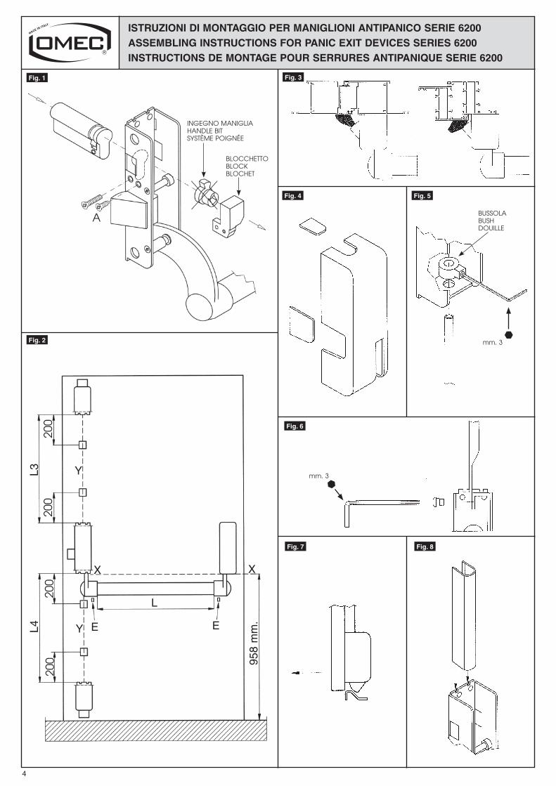
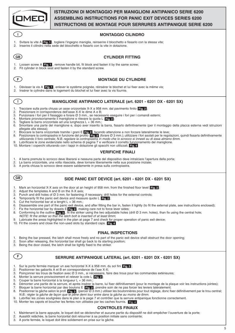
1. Svitare la vite A , togliere l’ingegno maniglia, reinserire il blocchetto e fissarlo con la stessa vite;2. Inserire il cilindro nella sede del blocchetto e fissarlo con la vite in dotazione.
I
Fig. 1
CYLINDER FITTING
1. Loosen screw A , remove handle bit, fit block and fasten it by the same screw;2. Fit cylinder in block seat and fasten it by the standard screw.
GB
Fig. 1
MONTAGE DU CYLINDRE
1. Dévisser la vis A , enlever le système poignée, réinsérer le blochet et lui fixer avec la même vis;2. Insérer le cylindre dans le logement du blochet et lui fixer avec la vis fournie.
F
Fig. 1
MANIGLIONE ANTIPANICO LATERALE (art. 6201 - 6201 DX - 6201 SX)
1. Tracciare sulla porta chiusa un asse orizzontale X-X a 958 mm. dal pavimento finito ;2. Posizionare in corrispondenza dell’asse X-X le dime A e B;3. Punzonare i fori per il fissaggio e forare Ø 3 mm., se necessario eseguire i fori per i comandi esterni; 4. Montare provvisoriamente il maniglione e rilevare la quota L ;5. Tagliare la barra orizzontale ad una lunghezza L + 36 mm.;6. Smontare una parte del maniglione e, dopo aver inserito la barra, fissarlo definitivamente (per il montaggio della placca esterna vedi istruzioni
allegate alla stessa);7. Bloccare la barra orizzontale tramite i grani E , facendo attenzione a non forzare lateralmente le leve;8. Posizionare la contropiastra in funzione del profilo , (forare Ø 3 mm.); utilizzare i fori asolati per le regolazioni, quindi fissarla definitivamente utilizzando il foro centrale; N.B. regolare la contropiastra in modo che lo scrocco si innesti su di essa almeno 6mm.9. Lubrificare le zone evidenziate nello schema di pagina 7 e verificare il corretto funzionamento del maniglione.10. Montare i coperchi otturando con i tappi in dotazione gli spacchi non utilizzati. .
VERIFICHE FINALI
1. A barra premuta lo scrocco deve liberarsi e nessuna parte del dispositivo deve intralciare l’apertura della porta;2. La barra orizzontale, una volta rilasciata, deve tornare liberamente nella sua posizione iniziale;3. A porta chiusa lo scrocco deve essere saldamente in presa sulla contropiastra.
I
Fig. 2
Fig. 2
Fig. 2Fig. 3
Fig. 4
SIDE PANIC EXIT DEVICE (art. 6201 - 6201 DX - 6201 SX)
1. Mark an horizontal X-X axis on the door at an height of 958 mm. from the finished floor level ;2. Adjust the templates A and B on the X-X axis;3. Punch and drill holes of Ø 3 mm. for fastening; if necessary, drill holes for the external controls; 4. Temporarily fit the panic exit device and measure quote L ;5. Cut the horizontal bar at a lenght L + 36 mm.;6. Disassemble one part of the panic exit device, and after fitting the bar in, fasten it tightly (to fit the external plate, see instructions enclosed);7. Fix the horizontal bar by dowels E , making care not to force lever sides;8. Conforming to the outline , fit the striker using the two adjustable holes (drill Ø 3 mm. holes), than fix using the central hole; NOTE: fit the striker so that the latch bolt is inserted of at least 6mm;9. Lubricate the areas highlighted in the plan at page 7 and check for proper operation of panic exit device;10. Fit the covers and close the non-used slots by standard caps.
FINAL INSPECTIONS1. Being the bar pressed, the latch shall move freely and no part of the panic exit device shall obstruct the door opening;2. Soon after releasing, the horizontal bar shall go back to its starting position;3. Being the door closed, the latch shall be tightly fixed to the striker.
GB
Fig. 2
Fig. 2
Fig. 2Fig. 3
Fig. 4
SERRURE ANTIPANIQUE LATERAL (art. 6201 - 6201 DX - 6201 SX)
1. Sur la porte fermée marquer un axe horizontal X-X à 958 mm. du sol fini ;2. Positionner les gabarits A et B en correspondance de l’axe X-X;3. Poinçonner les trous de fixation avec Ø 3 mm., si nécessaire, faire des trous pour les commandes extérieures; 4. Monter la serrure provisoirement et relever la cote L ;5. Couper la barre horizontal à la longueur L + 36 mm.;6. Démonter une partie de la serrure, et après insérer la barre, lui fixer définitivement (pour le montage de la plaque voir les instructions jointes);7. Bloquer la barre horizontal par des boulons E , prendre soin de ne pas forcer les leviers latéralement;8. Positionner la gâche selon le profi l , (percer Ø 3 mm.) utiliser les boutonnières pour tout réglage, donc fixer définitivement par le trou central; N.B.: règler la gâche de façon que le pêne demi tour entre dans la gâche au moins de 6mm.9. Lubrifier les zones soulignées dans le plan à la page 7 et contrôler que la serrure antipanique fonctionne correctement.10. Monter les capots et boucher les fentes non utilisées par les caches fournis. .
CONTROLES FINAUX1. Maintenant la barre appuyée, le loquet doit se déclencher et aucune partie du dispositif ne doit empêcher l’ouverture de la porte;2. Aussitôt relâchée, la barre horizontal doit retourner à sa position initiale sans contrainte;3. A porte fermée, le loquet doit être solidement en prise sur la gâche.
F
Fig. 2
Fig. 2
Fig. 2Fig. 3
Fig. 4
5
ISTRUZIONI DI MONTAGGIO PER MANIGLIONI ANTIPANICO SERIE 6200ASSEMBLING INSTRUCTIONS FOR PANIC EXIT DEVICES SERIES 6200INSTRUCTIONS DE MONTAGE POUR SERRURES ANTIPANIQUE SERIE 6200
6
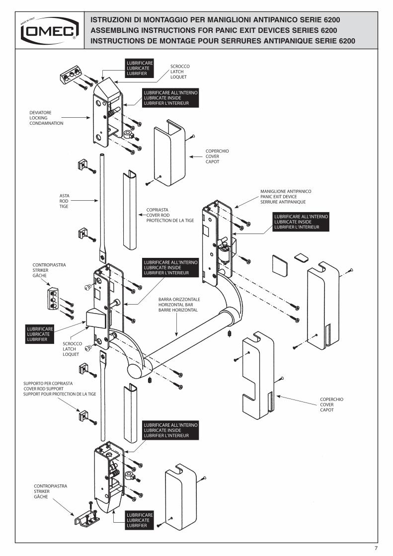
I MANIGLIONE ANTIPANICO TRIPLICE (art. 6202 - 6202 DX - 6202 SX - 6203 - 6203 DX - 6203 SX)CON KIT DEVIATORI ALTO/BASSO (art. 6030)
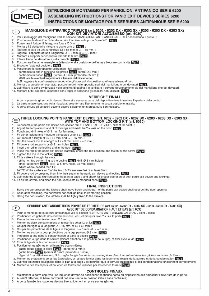
1. Per il montaggio del maniglione vedi la sezione “MANIGLIONE ANTIPANICO LATERALE” escludendo il punto 9;2. Posizionare le dime C e D dei deviatori e tracciare sulla porta l’asse Y-Y ;3. Punzonare i fori per il fissaggio e forare Ø 3 mm.; 4. Montare i 2 deviatori e rilevare le quote L3 e L4 ;5. Tagliare le aste ad una lunghezza L3 + 65 mm. e L4 + 65 mm. ;6. Tagliare i copriasta ad una lunghezza L3 + 3 mm. e L4 + 3 mm. ;7. Montare i supporti per copriasta forando Ø 3 mm. ;8. Infilare l’asta nel deviatore e nella bussola ;9. Posizionare l’asta nel maniglione (attenzione alla posizione dell’asta) e bloccare con la vite ;10. Bloccare l’asta nel deviatore ;11. Posizionare le contropiastre utilizzando i fori asolati: - contropiastra alta in funzione del profilo (forare Ø 3 mm.); - contropiastra bassa (forare Ø 5 mm. profondità 35 mm.); effettuare le eventuali regolazioni e fissarle definitivamente; N.B.: regolare le contropiastre in modo che gli scrocchi si innestino su di esse almeno 6 mm.12. Montare a pressione i copriasta, posizionandoli nelle apposite sedi del maniglione e dei deviatori ;13. Lubrificare le zone evidenziate nello schema di pagina 7 e verificare il corretto funzionamento sia del maniglione che dei deviatori;14. Montare tutti i coperchi, otturando con i tappi in dotazione gli spacchi non utilizzati .
VERIFICHE FINALI1. A barra premuta gli scrocchi devono liberarsi e nessuna parte del dispositivo deve intralciare l’apertura della porta;2. La barra orizzontale, una volta rilasciata, deve tornare liberamente nella sua posizione iniziale;3. A porta chiusa gli scrocchi devono essere saldamente in presa sulle contropiastre.
THREE LOCKING POINTS PANIC EXIT DEVICE (art. 6202 - 6202 DX - 6202 SX - 6203 - 6203 DX - 6203 SX)WITH TOP AND BOTTOM LOCKING KIT (art. 6030)
1. To assemble the panic exit device see section “SIDE PANIC EXIT DEVICE”, except for point 9;2. Adjust the templates C and D of lockings and mark the Y-Y axis on the door ;3. Punch and drill holes of Ø 3 mm. for fastening; 4. Fit either locking and measure the quotes L3 and L4 ;5. Cut rods at a length of L3 + 65 mm. and L4 + 65 mm. ;6. Cut the covers rod at a length of L3 + 3 mm. and L4 + 3 mm. ;7. Fit covers rod supports by Ø 3 mm. holes ;8. Insert the rod in the locking and in the bush ;9. Place the rod in the panic exit device (carefully check the rod position) and fasten by the screw ;10. Tighten the rod in the locking ;11. Fit te strikers through the slots: - striker on top conforming to the outline (drill Ø 3 mm. holes); - striker at bottom (drill Ø 5 mm. holes, 35 mm. deep); adjust where needed than fix; NOTE: fit the strikers so that the latch bolts are inserted of at least 6mm.12. Fit covers rod by pressing them into their seats in the panic exit device and locking ;13. Lubricate the areas highlighted in the plan at page 7 and check for proper operation of both panic exit device and lockings;14. Fit all the covers, and close the non-used slots by standard caps .
FINAL INSPECTIONS1. Being the bar pressed, the latches shall move freely and no part of the panic exit device shall obstruct the door opening;2. Soon after releasing, the horizontal bar shall go back to its starting position;3. Being the door closed, the latches shall be tightly fixed to the strikers.
SERRURE ANTIPANIQUE TROIS POINTS DE FERMETURE (art. 6202 - 6202 DX - 6202 SX - 6203 - 6203 DX - 6203 SX)AVEC KIT DE CONDAMNATION HAUT ET BAS (art. 6030)
1. Pour le montage de la serrure antipanique voir la section “SERRURE ANTIPANIQUE LATERAL” , point 9 exclu;2. Positionner les gabarits des condamnations C et D et marquer l’axe Y-Y sur la porte ;3. Percer les trous de fixation avec Ø 3 mm.; 4. Monter les deux condamnations et relever les cotes L3 et L4 ;5. Couper les tiges à la longueur L3 + 65 mm. et L4 + 65 mm. ;6. Couper les protections de la tige à la longueur L3 + 3 mm. et L4 + 3 mm. ;7. Monter les supports pour protections de la tige perçant Ø 3 mm. ;8. Introduire la tige dans la condamnation et dans la douille ;9. Positionner la tige dans la serrure (faisant attention à la position de la tige), et fixer avec la vis ;10. Fixer la tige dans la condamnation ;11. Positionner les gâches en utilisant les boutonnières: - gâche haute selon le profil (percer Ø 3 mm.); - gâche basse (percer Ø 5 mm. profondeur 35mm.); régler et fixer définitivement; N.B.: régler les gâches de façon que le pênes demi tour entrent dans les gâches au moins de 6 mm.12. Monter les protections de la tige à pression, et les positionner dans les logements relatifs de la serrure et de la condamnation ;13. Lubrifier les zones soulignées dans le plan à la page 7 et contrôler que la serrure antipanique et les condamnations fonctionnent correctement;14. Monter toutes les capots, et boucher les fentes non utilisées par les caches fournis .
CONTROLES FINAUX1. Maintenant la barre appuyée, les loquettes devons se déclencher et aucune partie du dispositif ne doit empêcher l’ouverture de la porte;2. Aussitôt relâchée, la barre horizontal doit retourner à sa position initiale sans contrainte;3. A porte fermée, les loquettes devons être solidement en prise sur les gâches.
GB
F
Fig. 2
Fig. 2
Fig. 2Fig. 5
Fig. 6Fig. 5
Fig. 3Fig. 7
Fig. 8
Fig. 4
Fig. 2
Fig. 2
Fig. 2
Fig. 5Fig. 6
Fig. 3Fig. 7
Fig. 5
Fig. 8
Fig. 4
Fig. 2
Fig. 2
Fig. 2Fig. 5
Fig. 6
Fig. 3Fig. 7
Fig. 5
Fig. 8
Fig. 4
7
ISTRUZIONI DI MONTAGGIO PER MANIGLIONI ANTIPANICO SERIE 6200ASSEMBLING INSTRUCTIONS FOR PANIC EXIT DEVICES SERIES 6200INSTRUCTIONS DE MONTAGE POUR SERRURES ANTIPANIQUE SERIE 6200
7
ISTRUZIONI DI MONTAGGIO PER MANIGLIONI ANTIPANICO SERIE 6200ASSEMBLING INSTRUCTIONS FOR PANIC EXIT DEVICES SERIES 6200INSTRUCTIONS DE MONTAGE POUR SERRURES ANTIPANIQUE SERIE 6200
SCROCCOLATCHLOQUET
DEVIATORELOCKINGCONDAMNATION
COPERCHIOCOVERCAPOT
MANIGLIONE ANTIPANICOPANIC EXIT DEVICESERRURE ANTIPANIQUE
BARRA ORIZZONTALEHORIZONTAL BARBARRE HORIZONTAL
COPRIASTACOVER RODPROTECTION DE LA TIGE
ASTARODTIGE
CONTROPIASTRASTRIKERGÂCHE
COPERCHIOCOVERCAPOT
CONTROPIASTRASTRIKERGÂCHE
LUBRIFICARELUBRICATELUBRIFIER
LUBRIFICARE ALL’INTERNOLUBRICATE INSIDELUBRIFIER L’INTERIEUR
LUBRIFICARE ALL’INTERNOLUBRICATE INSIDELUBRIFIER L’INTERIEUR
LUBRIFICARE ALL’INTERNOLUBRICATE INSIDELUBRIFIER L’INTERIEUR
SCROCCOLATCHLOQUET
LUBRIFICARELUBRICATELUBRIFIER
LUBRIFICARELUBRICATELUBRIFIER
LUBRIFICARE ALL’INTERNOLUBRICATE INSIDELUBRIFIER L’INTERIEUR
SUPPORTO PER COPRIASTACOVER ROD SUPPORTSUPPORT POUR PROTECTION DE LA TIGE

ISTRUZIONI DI MONTAGGIO PER MANIGLIONI ANTIPANICO SERIE 6200ASSEMBLING INSTRUCTIONS FOR PANIC EXIT DEVICES SERIES 6200INSTRUCTIONS DE MONTAGE POUR SERRURES ANTIPANIQUE SERIE 6200
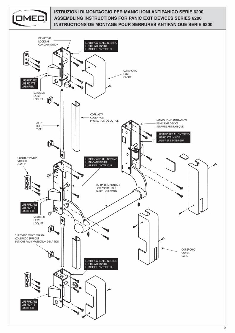
I MANIGLIONE ANTIPANICO TRIPLICE (art. 6202 - 6202 DX - 6202 SX - 6203 - 6203 DX - 6203 SX)CON KIT DEVIATORI LATERALI (art. 6031)
1. Per il montaggio del maniglione vedi la sezione “MANIGLIONE ANTIPANICO LATERALE” escludendo il punto 9;2. Posizionare le dime E ed F dei deviatori e tracciare sulla porta l’asse Y-Y ;3. Punzonare i fori per il fissaggio e forare Ø 3 mm.; 4. Montare i 2 deviatori e rilevare le quote L3 e L4 ;5. Tagliare le aste ad una lunghezza L3 + 46 mm. e L4 + 46 mm. ;6. Tagliare i copriasta ad una lunghezza L3 + 3 mm. e L4 + 3 mm. ;7. Montare i supporti per copriasta forando Ø 3 mm. ;8. Infilare l’asta nel deviatore e nella bussola ;9. Posizionare l’asta nel maniglione (attenzione alla posizione dell’asta) e bloccare con la vite ;10. Bloccare l’asta nel deviatore ;11. Posizionare le contropiastre in funzione del profilo (forare Ø 3 mm.), utilizzare i fori asolati per le regolazioni, quindi fissarle definitivamente
utilizzando il foro centrale; N.B.: regolare le contropiastre in modo che gli scrocchi si innestino su di esse almeno 6 mm.12. Montare a pressione i copriasta, posizionandoli nelle apposite sedi del maniglione e dei deviatori ;13. Lubrificare le zone evidenziate nello schema di pagina 9 e verificare il corretto funzionamento sia del maniglione che dei deviatori;14. Montare tutti i coperchi, otturando con i tappi in dotazione gli spacchi non utilizzati .
VERIFICHE FINALI
1. A barra premuta gli scrocchi devono liberarsi e nessuna parte del dispositivo deve intralciare l’apertura della porta;2. La barra orizzontale, una volta rilasciata, deve tornare liberamente nella sua posizione iniziale;3. A porta chiusa gli scrocchi devono essere saldamente in presa sulle contropiastre.
THREE LOCKING POINTS PANIC EXIT DEVICE (art. 6202 - 6202 DX - 6202 SX - 6203 - 6203 DX - 6203 SX)WITH SIDE LOCKING KIT (art. 6031)
1. To assemble the panic exit device see section “SIDE PANIC EXIT DEVICE”, except for point 9;2. Adjust the templates E and F of lockings and mark the Y-Y axis on the door ;3. Punch and drill holes of Ø 3 mm. for fastening; 4. Fit either locking and measure the quotes L3 and L4 ;5. Cut rods at a length of L3 + 46 mm. and L4 + 46 mm. ;6. Cut the covers rod at a length of L3 + 3 mm. and L4 + 3 mm. ;7. Fit covers rod supports by Ø 3 mm. holes ;8. Insert the rod in the locking and in the bush ;9. Place the rod in the panic exit device (carefully check the rod position) and fasten by the screw ;10. Tighten the rod in the locking ;11. Conforming to the outline fit the strikers using the two adjustable holes (drill Ø 3 mm. holes), than fix using the central hole; NOTE: fit the strikers so that the latch bolts are inserted of at least 6mm.12. Fit covers rod by pressing them into their seats in the panic exit device and locking ;13. Lubricate the areas highlighted in the plan at page 9 and check for proper operation of both panic exit device and lockings;14. Fit all the covers, and close the non-used slots by standard caps .
FINAL INSPECTIONS
1. Being the bar pressed, the latches shall move freely and no part of the panic exit device shall obstruct the door opening;2. Soon after releasing, the horizontal bar shall go back to its starting position;3. Being the door closed, the latches shall be tightly fixed to the strikers.
SERRURE ANTIPANIQUE TROIS POINTS DE FERMETURE (art. 6202 - 6202 DX - 6202 SX - 6203 - 6203 DX - 6203 SX)AVEC KIT DE CONDAMNATION LATERAL (art. 6031)
1. Pour le montage de la serrure antipanique voir la section “SERRURE ANTIPANIQUE LATERAL” , point 9 exclu;2. Positionner les gabarits des condamnations E et F et marquer l’axe Y-Y sur la porte ;3. Percer les trous de fixation avec Ø 3 mm.; 4. Monter les deux condamnations et relever les cotes L3 et L4 ;5. Couper les tiges à la longueur L3 + 46 mm. et L4 + 46 mm. ;6. Couper les protections de la tige à la longueur L3 + 3 mm. et L4 + 3 mm. ;7. Monter les supports pour protections de la tige perçant Ø 3 mm. ;8. Introduire la tige dans la condamnation et dans la douille ;9. Positionner la tige dans la serrure (faisant attention à la position de la tige), et fixer avec la vis ;10. Fixer la tige dans la condamnation ;11. Positionner les gâches selon le profil (percer Ø 3 mm.), utiliser les boutonnières pour tout réglage, donc fixer définitivement par le trou
central; N.B.: régler le gâches de façon que le pênes demi tour entre dans les gâches au moins de 6 mm.12. Monter les protections de la tige à pression, et les positionner dans les logements relatifs de la serrure et de la condamnation ;13. Lubrifier les zones soulignées dans le plan à la page 9 et contrôler que la serrure antipanique et les condamnations fonctionnent correctement;14. Monter toutes les capots, et boucher les fentes non utilisées par les caches fournis .
CONTROLES FINAUX
1. Maintenant la barre appuyée, les loquettes devons se déclencher et aucune partie du dispositif ne doit empêcher l’ouverture de la porte;2. Aussitôt relâchée, la barre horizontal doit retourner à sa position initiale sans contrainte;3. A porte fermée, les loquettes devons être solidement en prise sur les gâches.
GB
F
Fig. 2
Fig. 2
Fig. 2Fig. 5
Fig. 6Fig. 5
Fig. 3
Fig. 8
Fig. 4
Fig. 2
Fig. 2
Fig. 2Fig. 5
Fig. 6Fig. 5
Fig. 3
Fig. 8
Fig. 4
Fig. 2
Fig. 2
Fig. 2Fig. 5
Fig. 6Fig. 5
Fig. 3
Fig. 8
Fig. 4
8
9
ISTRUZIONI DI MONTAGGIO PER MANIGLIONI ANTIPANICO SERIE 6200ASSEMBLING INSTRUCTIONS FOR PANIC EXIT DEVICES SERIES 6200INSTRUCTIONS DE MONTAGE POUR SERRURES ANTIPANIQUE SERIE 6200
9
ISTRUZIONI DI MONTAGGIO PER MANIGLIONI ANTIPANICO SERIE 6200ASSEMBLING INSTRUCTIONS FOR PANIC EXIT DEVICES SERIES 6200INSTRUCTIONS DE MONTAGE POUR SERRURES ANTIPANIQUE SERIE 6200
DEVIATORELOCKINGCONDAMNATION
COPERCHIOCOVERCAPOT
MANIGLIONE ANTIPANICOPANIC EXIT DEVICESERRURE ANTIPANIQUE
BARRA ORIZZONTALEHORIZONTAL BARBARRE HORIZONTAL
COPRIASTACOVER RODPROTECTION DE LA TIGE
ASTARODTIGE
CONTROPIASTRASTRIKERGÂCHE
COPERCHIOCOVERCAPOT
SCROCCOLATCHLOQUET
LUBRIFICARELUBRICATELUBRIFIER
LUBRIFICARE ALL’INTERNOLUBRICATE INSIDELUBRIFIER L’INTERIEUR
LUBRIFICARELUBRICATELUBRIFIER
LUBRIFICARE ALL’INTERNOLUBRICATE INSIDELUBRIFIER L’INTERIEUR
LUBRIFICARE ALL’INTERNOLUBRICATE INSIDELUBRIFIER L’INTERIEUR
LUBRIFICARE ALL’INTERNOLUBRICATE INSIDELUBRIFIER L’INTERIEUR
SUPPORTO PER COPRIASTACOVER ROD SUPPORTSUPPORT POUR PROTECTION DE LA TIGE
SCROCCOLATCHLOQUET
LUBRIFICARELUBRICATELUBRIFIER
ISTRUZIONI DI MONTAGGIO PER MANIGLIONI ANTIPANICO SERIE 6200ASSEMBLING INSTRUCTIONS FOR PANIC EXIT DEVICES SERIES 6200INSTRUCTIONS DE MONTAGE POUR SERRURES ANTIPANIQUE SERIE 6200
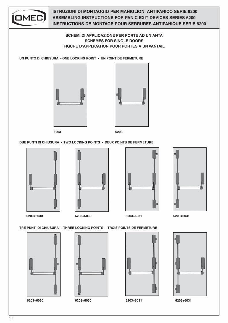
SCHEMI DI APPLICAZIONE PER PORTE AD UN’ANTASCHEMES FOR SINGLE DOORS
FIGURE D’APPLICATION POUR PORTES A UN VANTAIL
DUE PUNTI DI CHIUSURA - TWO LOCKING POINTS - DEUX POINTS DE FERMETURE
UN PUNTO DI CHIUSURA - ONE LOCKING POINT - UN POINT DE FERMETURE
TRE PUNTI DI CHIUSURA - THREE LOCKING POINTS - TROIS POINTS DE FERMETURE
10
6203
6203+6030
6203+6030
6203+6031
6203+6031
6203+6030
6203+6030
6203+6031
6203+6031
6203
ISTRUZIONI DI MONTAGGIO PER MANIGLIONI ANTIPANICO SERIE 6200ASSEMBLING INSTRUCTIONS FOR PANIC EXIT DEVICES SERIES 6200INSTRUCTIONS DE MONTAGE POUR SERRURES ANTIPANIQUE SERIE 6200
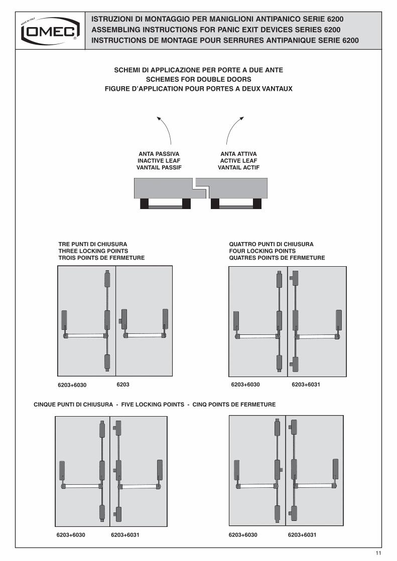
SCHEMI DI APPLICAZIONE PER PORTE A DUE ANTESCHEMES FOR DOUBLE DOORS
FIGURE D’APPLICATION POUR PORTES A DEUX VANTAUX
QUATTRO PUNTI DI CHIUSURAFOUR LOCKING POINTSQUATRES POINTS DE FERMETURE
TRE PUNTI DI CHIUSURA THREE LOCKING POINTS TROIS POINTS DE FERMETURE
ANTA PASSIVAINACTIVE LEAFVANTAIL PASSIF
ANTA ATTIVAACTIVE LEAF
VANTAIL ACTIF
CINQUE PUNTI DI CHIUSURA - FIVE LOCKING POINTS - CINQ POINTS DE FERMETURE
11
6203+6030
6203+6030
6203+6030
6203+6030
6203+6031
6203+6031
6203
6203+6031
ISM
-07-
00
UR
0515
ISTRUZIONI DI MONTAGGIO PER MANIGLIONI ANTIPANICO SERIE 6200ASSEMBLING INSTRUCTIONS FOR PANIC EXIT DEVICES SERIES 6200INSTRUCTIONS DE MONTAGE POUR SERRURES ANTIPANIQUE SERIE 6200
GB
GB
F
F
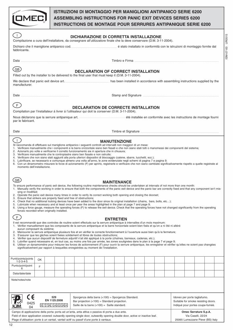
MANUTENZIONESi raccomanda di effettuare sul maniglione antipanico i seguenti controlli ad intervalli non maggiori di un mese:1. Verificare manualmente che i componenti e la barra orizzontale siano ben fissati e che non siano stati tolti o manomessi dei componenti del sistema;2. Azionarlo più volte e verificarne il corretto funzionamento sia in apertura che in chiusura;3. Verificare manualmente che le contropiastre siano ben fissate e non ostruite;4. Verificare che non siano stati aggiunti alla porta ulteriori dispositivi di bloccaggio (catene, sbarre, lucchetti, ecc.);5. Lubrificare, se necessario e comunque almeno una volta all’anno, le zone evidenziate negli schemi di pagina 7 e pagina 9;6. Con un dinamometro misurare le forze di azionamento (F) per aprirlo, registrarle e verificare che non siano cambiate significativamente rispetto a quelle registrate al
momento dell’installazione.
DICHIARAZIONE DI CORRETTA INSTALLAZIONECompilazione a cura dell’installatore, da consegnare all’utilizzatore finale che la deve conservare (D.M. 3-11-2004).
Dichiaro che il maniglione antipanico cod. é stato installato in conformità con le istruzioni di montaggio fornite dalfabbricante.
Data Timbro e Firma
I
I
12
MAINTENANCETo ensure performance of panic exit device, the following routine maintenance checks should be undertaken at intervals of not more than one month:1. Manually verify the working in order to ensure that both the components of the panic exit device and the panic bar are correctly fixed and that any component isn’t mis-
sing or modified;2. Operate the panic exit device many times in order to verify its correct working both opening and closing the doorset;3. Ensure that strikers are properly fixed and free of obstructions;4. Check that no additional locking devices have been added to the door since its original installation (chains, bars, bolts, etc…);5. Lubricate when necessary and at least once per year the areas highlighted in the plan at page 7 and page 9;6. Using a force gauge, measure the operating forces (F) to release the exit device. Check that the operating forces have not changed significantly from the operating
forces recorded when originally installed.
DECLARATION OF CORRECT INSTALLATIONFilled out by the installer to be delivered to the final user that must keep it (D.M. 3-11-2004).
We declare that panic exit device art. has been installed in accordance with assembling instructions supplied by themanufacturer.
Date Stamp and Signature
ENTRETIENIl est recommandé que des controles de routine soient effectués sur la serrure antipanique à intervalles d’un mois maximum:1. Vérifier manuellement que les composants de la serrure antipanique et la barre horizontale soient bien fixés et qu’on a ni ôté ni altéré aucun composant du sistème;2. Manouvrer la serrure antipanique plusieurs fois et en vérifier le correcte fonctionnement à l’ouverture aussi bien qu’à la fermeture;3. S’assurer que les gâches soient fixées solidement et libres de toutes obstructions; 4. Vérifier que aucun dispositif de fermeture adjuntif n’ait été appliqué à la porte (chaînes, barreaux, cadenas, etc.);5. Lubrifier quand nécessaire et, en tout cas, au moins une fois par année, les zones soulignées dans le plan à la page 7 et page 9;6. Utiliser un dynamomètre pour mésurer les forces de actionnement (F) pour ouvrir la serrure antipanique, les enregistrer et vérifier qu’elles ne soient pas changées
significativement par rapport à lesquelles enregistrées au moment de l’installation.
DECLARATION DE CORRECTE INSTALLATIONCompilation par l’installateur á livrer á l’utilisateur qui doit la conserver (D.M. 3-11-2004).
Nous déclarons que la serrure antipanique art. étè installée en conformite avec les instructions de montage fourni par le fabricant.
Date Timbre et Signature
Sporgenza della barra (<100) = Sporgenza Standard.Bar projection (<100) = Standard projection.Saille de la barre (<100) = Saille standard.
Note/notes/note
Punti/points/points1-2-3-4-5
OK
Punto/point/point6
F
Data/date/date
Idoneo per porte tagliafumo.Suitable for smoke resisting doors.Indiqué pour portes coupe-fuméè.
Campo di applicazione della porta: porta ad un’anta, anta attiva o passiva di porta a due ante.Field of door application covered: outwardly opening single door, outwardly opening double door, active or inactive leaf.Plage d’utilisation: porte à un vantail, vantail actif ou passif d’une porte à vantaux.
Omec Serrature S.p.A.Via Caselli, 22/24
25065 Lumezzane Pieve (BS) Italy
042504
529EN 1125:2008
3 7 7 A 1 4 2 2 A A