Introduzione alle reti DVB-H - riccardogalletti.com · UNIVERSITA DEGLI STUDI DI CASSINO`...
43
UNIVERSIT ` A DEGLI STUDI DI CASSINO FACOLTA’ DI INGEGNERIA Corso di sistemi radiomobili Introduzione alle reti DVB-H Gianfranco Miele 8 giugno 2007 © Gianfranco Miele scaricato da www.riccardogalletti.com/appunti_gratis - APPUNTI INGEGNERIA GRATIS
Transcript of Introduzione alle reti DVB-H - riccardogalletti.com · UNIVERSITA DEGLI STUDI DI CASSINO`...

UNIVERSITA DEGLI STUDI DI CASSINO
FACOLTA’ DI INGEGNERIA
Corso di sistemi radiomobili
Introduzione alle reti DVB-H
Gianfranco Miele
8 giugno 2007
© Gianfranco Miele
scaricato da www.riccardogalletti.com/appunti_gratis - APPUNTI INGEGNERIA GRATIS
Contents
1 DVB-T system 11.1 Introduction . . . . . . . . . . . . . . . . . . . . . . . . . . . . . . . . 11.2 General considerations . . . . . . . . . . . . . . . . . . . . . . . . . . 21.3 Channel coding . . . . . . . . . . . . . . . . . . . . . . . . . . . . . . 4
1.3.1 Transport multiplex adaptation and randomization for energydispersal . . . . . . . . . . . . . . . . . . . . . . . . . . . . . . 4
1.3.2 Outer coding . . . . . . . . . . . . . . . . . . . . . . . . . . . 51.3.3 Outer interleaver . . . . . . . . . . . . . . . . . . . . . . . . . 61.3.4 Inner coding . . . . . . . . . . . . . . . . . . . . . . . . . . . . 61.3.5 Inner interleaver . . . . . . . . . . . . . . . . . . . . . . . . . 71.3.6 Signal constellation and mapping . . . . . . . . . . . . . . . . 11
1.4 OFDM frame structure . . . . . . . . . . . . . . . . . . . . . . . . . . 131.5 Reference signals . . . . . . . . . . . . . . . . . . . . . . . . . . . . . 16
1.5.1 Location of scattered pilot cells . . . . . . . . . . . . . . . . . 171.5.2 Location of continual pilot cells . . . . . . . . . . . . . . . . . 17
1.6 Transmission Parameter Signalling (TPS) . . . . . . . . . . . . . . . . 181.6.1 TPS transmission format . . . . . . . . . . . . . . . . . . . . . 191.6.2 TPS modulation . . . . . . . . . . . . . . . . . . . . . . . . . 23
1.7 DVB-T system parameter summary and net data rate . . . . . . . . . 241.8 Spectrum characteristics . . . . . . . . . . . . . . . . . . . . . . . . . 251.9 Time-domain signal characteristics . . . . . . . . . . . . . . . . . . . 26
A Additional features for DVB Handheld terminals (DVB-H) 29A.1 Introduction . . . . . . . . . . . . . . . . . . . . . . . . . . . . . . . . 29A.2 Channel coding and modulation . . . . . . . . . . . . . . . . . . . . . 30
A.2.1 Inner interleaving . . . . . . . . . . . . . . . . . . . . . . . . . 30A.3 OFDM frame structure . . . . . . . . . . . . . . . . . . . . . . . . . . 33A.4 Reference signals . . . . . . . . . . . . . . . . . . . . . . . . . . . . . 33
A.4.1 Location of continual pilot carriers . . . . . . . . . . . . . . . 33A.5 Transmission Parameter Signalling (TPS) . . . . . . . . . . . . . . . . 34
A.5.1 TPS transmission format . . . . . . . . . . . . . . . . . . . . . 34
I
© Gianfranco Miele
scaricato da www.riccardogalletti.com/appunti_gratis - APPUNTI INGEGNERIA GRATIS

Bibliography 37
II
© Gianfranco Miele
scaricato da www.riccardogalletti.com/appunti_gratis - APPUNTI INGEGNERIA GRATIS
Chapter 1
DVB-T system
1.1 Introduction
The DVB Project is an alliance of about 250-300 public and private media interestcompanies, originally of European origin but now worldwide.
Until late 1990, digital television broadcasting to the home was thought to be im-practical and costly to implement. During 1991, broadcasters and consumer equip-ment manufacturers discussed how to form a concerted pan-European platform todevelop digital terrestrial TV. Towards the end of that year, broadcasters, consumerelectronics manufacturers and regulatory bodies came together to discuss the forma-tion of a group that would oversee the development of digital television in Europe.
This group was called European Launching Group (ELG), that provided to drafta protocol named, Memorandum of Understanding (MoU), establishing the rules tobe adopted and respected by the members of the group. The Mou was signed by allELG participants in September 1993, and the Launching Group renamed itself asthe Digital Video Broadcasting Project (DVB).
DVB project has a bicameral structure:
• Commercial Module decides what features or cost levels are needed to make aproduct a success.
• Technical Module is set the task of creating a technical specification whichmeets the needs asked by the Commercial Module.
Finally, after the specification is prepared, the commercial module checks the tech-nicians have done what was needed. Afterwards specifications are passed to theEuropean standards body for media systems, the European Broadcasting Union(EBU)/Comite Europeen de Normalisation ELECtrotechnique (CENELEC)/EuropeanTelecommunications Standards Institute (ETSI), for approval. The specifications arethen formally standardised by either CENELEC or, in the majority of cases, ETSI.
1
© Gianfranco Miele
scaricato da www.riccardogalletti.com/appunti_gratis - APPUNTI INGEGNERIA GRATIS

1 – DVB-T system
The first digital video broadcasting platform developed was the DVB-S systemfor digital satellite broadcasting, in 1993. It is a relatively straightforward systemusing QPSK modulation scheme and was introduced by the standard ETSI EN 300421, approved in 1997. This standard describes different tools for channel codingand error protection which were later used for other delivery media systems [1].
The DVB-C system for digital cable networks was developed in 1994. It is centredon the use of 64-QAM modulation scheme, and for the European satellite and cableenvironment can, if needed, convey a complete satellite channel multiplex on a cablechannel. The specification are described by the ETSI EN 300 429 standard [2].
Though digital television broadcasting via satellite and cable are accessible tomany households throughout the world, the DVB project decided to design an ad-ditional coverage with digital terrestrial television for the following reasons [3]:
• Many countries in the world do not have satellite TV coverage, or only in-adequately so, for the most varied reasons of a political, geographic or othernature. In many cases, substitute coverage by cable is not possible, either,because e.g. permafrost and also often can be financed because of sparsepopulation density. This leaves only the terrestrial coverage.
• The previous systems are not able to supply local supplementary municipalservices (regional/urban television).
• Portable and mobile reception is virtually only possible via the terrestrial path.
In 1995, the terrestrial standard for the trasmission of digital TV programs wasdefined in (EN 300 744) [4]. This standard was more complex because it was intendedto cope with a different noise and bandwidth environment, and multi-path. Thekey element is the use of the Orthogonal Frequency Division Multiplexing (OFDM).There are two transmission modes: the 8K mode, that allows more multi-pathfading protection and 2K mode, that offers Doppler advantages where the receiveris moving.
In this chapter is carried out an exhaustive description of the DVB-T standard[4], focusing the attention to the transmitter structure and to the typical character-istics of the modulated signal.
1.2 General considerations
The trasmitting chain of a DVB-T transmitter can be sketched by functional blockswith the aim to adapt the baseband TV signals from the output of the MPEG-2 transport multiplexer, to the terrestrial channel characteristics (see figure 1.1).The system is designed to be directly compatible with MPEG-2 coded TV signals(ISO/IEC 13818 )[5].
2
© Gianfranco Miele
scaricato da www.riccardogalletti.com/appunti_gratis - APPUNTI INGEGNERIA GRATIS

1.2 – General considerations
Figure 1.1. Functional block diagram of a DVB-T transmitter
Since the system is being designed for digital terrestrial television services tooperate within the existing VHF (Very High Frequency) and UHF (Ultra High Fre-quency) spectrum allocation for analogue transmissions, it is required that the Sys-tem provides sufficient protection against high levels of Co-Channel Interference(CCI) and Adjacent Channel Interference (ACI) emanating from existing PAL/SECAM/NTSCservices. It is also a requirement that the System allows the maximum spectrum effi-ciency when used within the VHF and UHF bands; this requirement can be achievedby utilizing Single Fequency Network (SFN) operation.
To allow optimal trade off between network topology and frequency efficiency,a flexible guard interval is specified. This enable the system to support differentnetwork configurations, such as large area SFN and single transmitter, while keepingmaximum frequency efficiency.
Furthermore the standard [4] specifies two transmission modes. The 2K modeis suitable for single transmitter operation and for small SFN networks with limitedtransmitter distances. The 8K mode can be used both for single transmitter oper-ation and for small and large SFN networks. Exclusively for use in Digital VideoBroadcasting-Handheld (DVB-H) systems, a third transmission mode is defined 4K.This additional trasmission mode permits to offer an additional trade-off between
3
© Gianfranco Miele
scaricato da www.riccardogalletti.com/appunti_gratis - APPUNTI INGEGNERIA GRATIS

1 – DVB-T system
transmission cell size and mobile reception capabilities, providing an additional de-gree of flexibility for DVB-H network planning.
The system allows different levels of QAM modulation and different inner coderates. The system also allows two level hierarchical channel coding and modulation,including uniform and multi-resolution constellation. In this case the functionalblock diagram of the system shall be expanded to include the modules shown dashedin figure 1.1. Two independent MPEG transport streams, referred to as the high-priority and the low-priority stream, are mapped onto the signal constellation by themapper and the modulator which therefore has a corresponding number of inputs.
1.3 Channel coding
The first five functional blocks have the channel coding task. These blocks are:
• Transport multiplex adaptation and randomization for energy dispersal;
• Outer coding;
• Outer interleaver;
• Inner coder;
• Inner interleaver.
Afterwards will be given a detailed description of each single block operation.
1.3.1 Transport multiplex adaptation and randomization forenergy dispersal
The System input stream shall be organized in fixed length packets coming from theMPEG-2 transport multiplexer. The total packet length of the MPEG-2 transportmultiplex (MUX) packet is 188 bytes (figure 1.2).
Figure 1.2. MPEG-2 transport multiplexer packet
These packets are composed by 1 sync-word byte SYNC (47HEX) and 187 databytes.
4
© Gianfranco Miele
scaricato da www.riccardogalletti.com/appunti_gratis - APPUNTI INGEGNERIA GRATIS

1.3 – Channel coding
Figure 1.3. Scrambler/descrambler schematic diagram
This data stream is randomized using a scrambler-descrambler, depicted in fig-ure 1.3. Scrambler-descrambler uses a Pseudo Random Binary Sequence (PRBS)generator, and the polynomial for the generator is given by
1 + X14 + X15. (1.1)
The PRBS register is initiated at the start of every eight transport packets load-ing into it the initialization sequence 100101010000000. To provide an initializationsignal for the descrambler, the MPEG-2 sync byte of the first transport packet in agroup of eight packets is bit-wise inverted from 47HEX to B8HEX (figure 1.4).
Figure 1.4. Randomized transport packets
The first bit at the output of the PRBS generator shall be applied to the firstbit of the first byte following the inverted MPEG-2 sync byte. To aid other synchro-nization functions, during the MPEG-2 sync bytes of the subsequent seven transportpackets, the PRBS generation shall continue, but its output shall be disabled, leav-ing these bytes unrandomized. Thus, the period of the PRBS sequence shall be 1503bytes.
1.3.2 Outer coding
The outer coding and interleaving is performed by a Reed-Solomon RS(204,188,t =8) shortned code. This code is applied to each randomized transport packet of 188bytes, generating an error protected packet 204 bytes long, consisting of 188 data
5
© Gianfranco Miele
scaricato da www.riccardogalletti.com/appunti_gratis - APPUNTI INGEGNERIA GRATIS
1 – DVB-T system
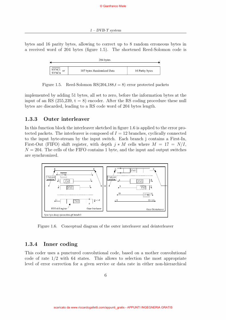
bytes and 16 parity bytes, allowing to correct up to 8 random erroneous bytes ina received word of 204 bytes (figure 1.5). The shortened Reed-Solomon code is
Figure 1.5. Reed-Solomon RS(204,188,t = 8) error protected packets
implemented by adding 51 bytes, all set to zero, before the information bytes at theinput of an RS (255,239, t = 8) encoder. After the RS coding procedure these nullbytes are discarded, leading to a RS code word of 204 bytes length.
1.3.3 Outer interleaver
In this function block the interleaver sketched in figure 1.6 is applied to the error pro-tected packets. The interleaver is composed of I = 12 branches, cyclically connectedto the input byte-stream by the input switch. Each branch j contains a First-In,First-Out (FIFO) shift register, with depth j ∗ M cells where M = 17 = N/I,N = 204. The cells of the FIFO contains 1 byte, and the input and output switchesare synchronized.
Figure 1.6. Conceptual diagram of the outer interleaver and deinterleaver
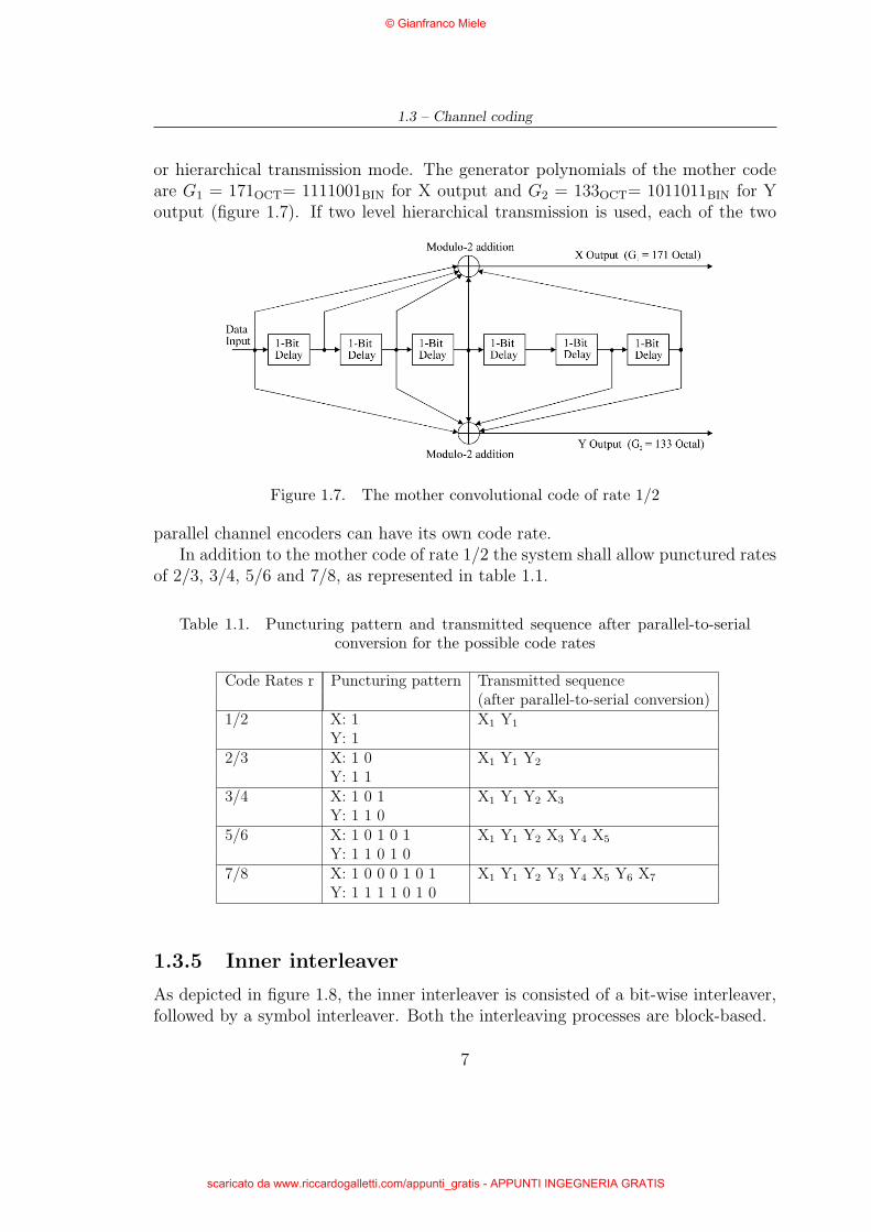
1.3.4 Inner coding
This coder uses a punctured convolutional code, based on a mother convolutionalcode of rate 1/2 with 64 states. This allows to selection the most appropriatelevel of error correction for a given service or data rate in either non-hierarchical
6
© Gianfranco Miele
scaricato da www.riccardogalletti.com/appunti_gratis - APPUNTI INGEGNERIA GRATIS
1.3 – Channel coding
or hierarchical transmission mode. The generator polynomials of the mother codeare G1 = 171OCT= 1111001BIN for X output and G2 = 133OCT= 1011011BIN for Youtput (figure 1.7). If two level hierarchical transmission is used, each of the two
Figure 1.7. The mother convolutional code of rate 1/2
parallel channel encoders can have its own code rate.In addition to the mother code of rate 1/2 the system shall allow punctured rates
of 2/3, 3/4, 5/6 and 7/8, as represented in table 1.1.
Table 1.1. Puncturing pattern and transmitted sequence after parallel-to-serialconversion for the possible code rates
Code Rates r Puncturing pattern Transmitted sequence(after parallel-to-serial conversion)
1/2 X: 1 X1 Y1
Y: 12/3 X: 1 0 X1 Y1 Y2
Y: 1 13/4 X: 1 0 1 X1 Y1 Y2 X3
Y: 1 1 05/6 X: 1 0 1 0 1 X1 Y1 Y2 X3 Y4 X5
Y: 1 1 0 1 07/8 X: 1 0 0 0 1 0 1 X1 Y1 Y2 Y3 Y4 X5 Y6 X7
Y: 1 1 1 1 0 1 0
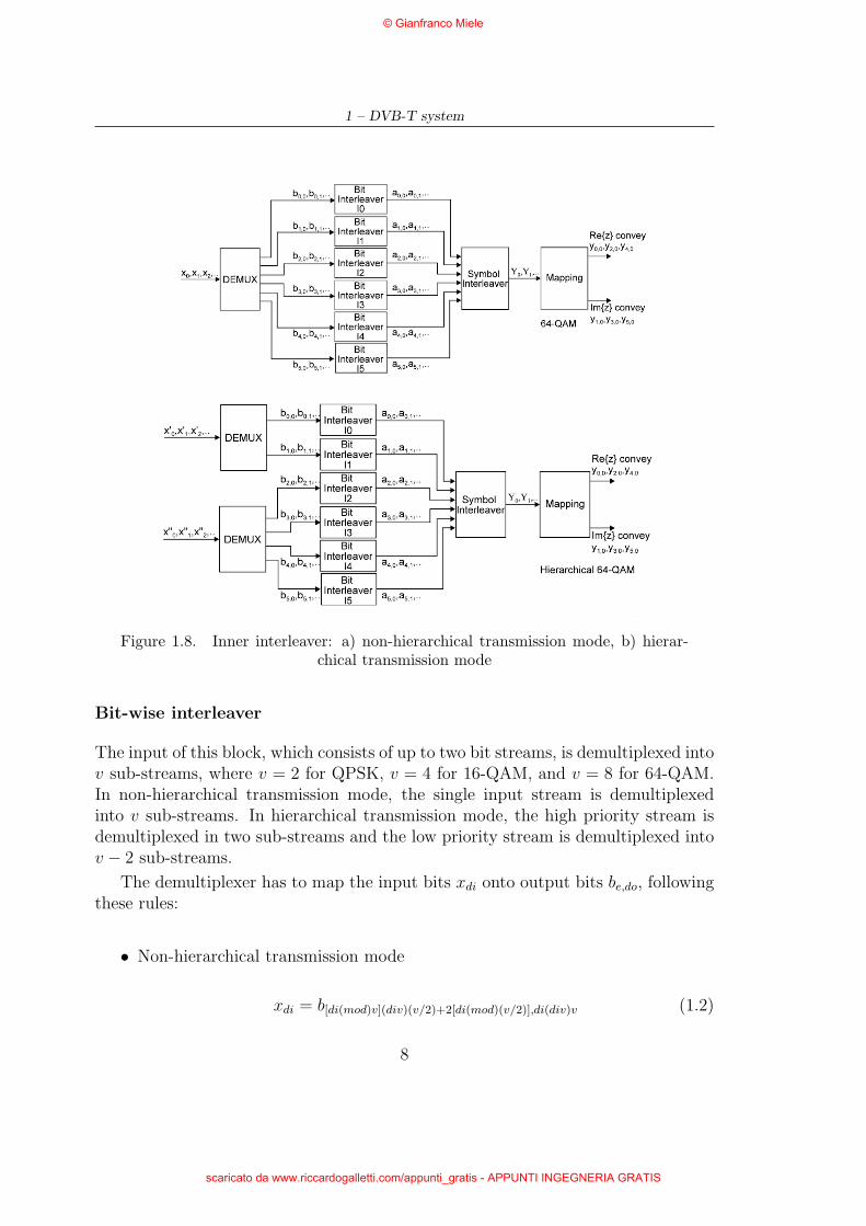
1.3.5 Inner interleaver
As depicted in figure 1.8, the inner interleaver is consisted of a bit-wise interleaver,followed by a symbol interleaver. Both the interleaving processes are block-based.
7
© Gianfranco Miele
scaricato da www.riccardogalletti.com/appunti_gratis - APPUNTI INGEGNERIA GRATIS
1 – DVB-T system
Figure 1.8. Inner interleaver: a) non-hierarchical transmission mode, b) hierar-chical transmission mode
Bit-wise interleaver
The input of this block, which consists of up to two bit streams, is demultiplexed intov sub-streams, where v = 2 for QPSK, v = 4 for 16-QAM, and v = 8 for 64-QAM.In non-hierarchical transmission mode, the single input stream is demultiplexedinto v sub-streams. In hierarchical transmission mode, the high priority stream isdemultiplexed in two sub-streams and the low priority stream is demultiplexed intov − 2 sub-streams.
The demultiplexer has to map the input bits xdi onto output bits be,do, followingthese rules:
• Non-hierarchical transmission mode
xdi = b[di(mod)v](div)(v/2)+2[di(mod)(v/2)],di(div)v (1.2)
8
© Gianfranco Miele
scaricato da www.riccardogalletti.com/appunti_gratis - APPUNTI INGEGNERIA GRATIS

1.3 – Channel coding
• Hierachical transmission mode
x′di = bdi(mod)2,di(div)2
x′′di = b[di(mod)(v−2)](div)((v−2)/2)+2[di(mod)((v−2)/2)]+2,di(div)(v−2)(1.3)
where:
- xdi is the input to the demultiplexer in non-hierarchical mode;
- x′di is the high priority input to the demultiplexer;
- x′′di is the low priority input, in hierarchical mode;
- di is the input bit number;
- be,do is the output from the demultiplexer;
- e is the demultiplexed bit stream number (0 ≤ e < v);
- do is the bit number of a given stream at the output of the demultiplexer;
- mod is the integer modulo operator;
- div is the integer division operator.
Each sub-stream from the demultiplexer is processed by a separate bit interleaver.There are therefore up to six interleavers depending on v, labelled I0 to I5. Each ofthese interlevers works on a block size of 126 bits, but the interleaving sequence isdifferent in each case. The block interleaving process is therefore repeated exactlytwelve times per OFDM symbol of useful data in the 2K mode and forty-eight timesper symbol in the 8K mode.
For each bit interleaver, the input bit vector is defined by:
B(e) = (be,0,be,1,be,2, . . . ,be,125) (1.4)
where e ranges from 0 to v − 1.The interleaved output vector A(e) = (ae,0,ae,1,ae,2, . . . ,ae,125) is defined by:
ae,w = be,He(w) w = 0,1,2, . . . ,125 (1.5)
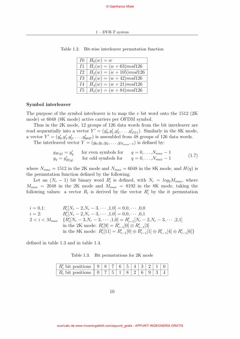
where He(w) is a permutation function which is different for each interleaver, definedin table 1.2.
The outputs of the v bit interleavers are grouped to form the digital data symbols,such that each symbol of v bits will consist of exactly one bit from each of the vinterleavers. Hence, the output from the bit-wise interleaver is a v bit word y′, thathas the output of I0 as its most significant bit:
y′w = (a0,w,a1,w, . . . ,av−1,w) (1.6)
9
© Gianfranco Miele
scaricato da www.riccardogalletti.com/appunti_gratis - APPUNTI INGEGNERIA GRATIS
1 – DVB-T system
Table 1.2. Bit-wise interleaver permutation function
I0 H0(w) = wI1 H1(w) = (w + 63)mod126I2 H2(w) = (w + 105)mod126I3 H3(w) = (w + 42)mod126I4 H4(w) = (w + 21)mod126I5 H5(w) = (w + 84)mod126
Symbol interleaver
The purpose of the symbol interleaver is to map the v bit word onto the 1512 (2Kmode) or 6048 (8K mode) active carriers per OFDM symbol.
Thus in the 2K mode, 12 groups of 126 data words from the bit interleaver areread sequentially into a vector Y ′ = (y′0,y
′1,y
′2, . . . ,y
′1511). Similarly in the 8K mode,
a vector Y ′ = (y′0,y′1,y
′2, . . . ,y
′6047) is assembled from 48 groups of 126 data words.
The interleaved vector Y = (y0,y1,y2, . . . ,yNmax−1) is defined by:
yH(q) = y′q for even symbols for q = 0, . . . ,Nmax − 1yq = y′H(q) for odd symbols for q = 0, . . . ,Nmax − 1
(1.7)
where Nmax = 1512 in the 2K mode and Nmax = 6048 in the 8K mode, and H(q) isthe permutation function defined by the following.
Let an (Nr − 1) bit binary word R′i is defined, with Nr = log2Mmax, where
Mmax = 2048 in the 2K mode and Mmax = 8192 in the 8K mode, taking thefollowing values: a vector Ri is derived by the vector R′
i by the it permutation
i = 0,1: R′i[Nr − 2,Nr − 3, · · · ,1,0] = 0,0, · · · ,0,0
i = 2: R′i[Nr − 2,Nr − 3, · · · ,1,0] = 0,0, · · · ,0,1
2 < i < Mmax {R′i[Nr − 3,Nr − 3, · · · ,1,0] = R′
i−1[Nr − 2,Nr − 3, · · · ,2,1]in the 2K mode: R′
i[9] = R′i−1[0]⊕R′
i−1[3]in the 8K mode: R′
i[11] = R′i−1[0]⊕R′
i−1[1]⊕R′i−1[4]⊕R′
i−1[6]}
defined in table 1.3 and in table 1.4.
Table 1.3. Bit permutations for 2K mode
R′i bit positions 9 8 7 6 5 4 3 2 1 0
Ri bit positions 0 7 5 1 8 2 6 9 3 4
10
© Gianfranco Miele
scaricato da www.riccardogalletti.com/appunti_gratis - APPUNTI INGEGNERIA GRATIS
1.3 – Channel coding
Table 1.4. Bit permutations for 8K mode
R′i bit positions 11 10 9 8 7 6 5 4 3 2 1 0
Ri bit positions 5 11 3 0 10 8 6 9 2 4 1 7
The permutation function H(q) is defined by the following algorithm:
q = 0for(i = 0; i < Mmax; i = i + 1)
{H(q) = (imod2)2Nr−1 +Nr−2∑j=0
Ri[j]2j;
if(H(q) < Nmax) q = q + 1;}
In similar way to y′, y is made up of v bits:
yq′ = (y0,q′ ,y1,q′ , . . . ,yv−1,q′) (1.8)
where q′ is the symbol number at the output of the symbol interleaver. These valuesof y are used to map the data into the signal constellation, as described in the nextparagraph.
1.3.6 Signal constellation and mapping
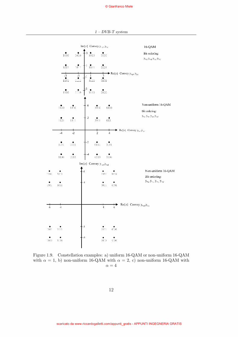
As said previous the system uses ODFM transmission. All data carriers in oneOFDM frame are modulated using either QPSK, 16-QAM, 64-QAM, non-uniform16-QAM or non-uniform 64-QAM constellations (see the examples in figure 1.9).All constellations are made using the Gray mapping.
The exact proportions of the constellations depend on the parameter α, which cantake three values 1,2,or 4. α is the minimum distance separating two constellationpoints carrying different HP-bit values divided by the minimum distance separatingany two constellation points.
The exact values of the constellation points are z ∈ {n + jm} with values of n,m given below for the various constellations:
• QPSK
n ∈ {−1,1}, m ∈ {−1,1}• 16-QAM (uniform and non-uniform with α = 1)
n ∈ {−3,− 1,1,3}, m ∈ {−3,− 1,1,3}• non-uniform 16-QAM with α = 2
11
© Gianfranco Miele
scaricato da www.riccardogalletti.com/appunti_gratis - APPUNTI INGEGNERIA GRATIS
1 – DVB-T system
Figure 1.9. Constellation examples: a) uniform 16-QAM or non-uniform 16-QAMwith α = 1, b) non-uniform 16-QAM with α = 2, c) non-uniform 16-QAM with
α = 4
12
© Gianfranco Miele
scaricato da www.riccardogalletti.com/appunti_gratis - APPUNTI INGEGNERIA GRATIS

1.4 – OFDM frame structure
n ∈ {−4,− 2,2,4}, m ∈ {−4,− 2,2,4}• non-uniform 16-QAM with α = 4
n ∈ {−6,− 4,4,6}, m ∈ {−6,− 4,4,6}• 64-QAM (uniform and non-uniform with α = 1)
n ∈ {−7,− 5,− 3,− 1,1,3,5,7}, m ∈ {−7,− 5,− 3,− 1,1,3,5,7}• non-uniform 64-QAM with α = 2
n ∈ {−8,− 6,− 4,− 2,2,4,6,8}, m ∈ {−8,− 6,− 4,− 2,2,4,6,8}• non-uniform 64-QAM with α = 4
n ∈ {−10,− 8,− 6,− 4,4,6,8,10}, m ∈ {−10,− 8,− 6,− 4,4,6,8,10}
Non-hierarchical transmission
The data stream at the output of the inner interleaver consists of v bit words, thatare mapped onto a complex number z, in according to one of the three uniformconstellations described above.
Hierarchical transmission
In the case of hierarchical transmission, the data streams are formatted as shown infigure 1.8 b), and then the used constellations are only that non-uniform ones.In particular in this case the high priority bits are the first two bits of the innerinterleaver output word (y0,q′ ,y1,q′). Thanks to the Gray mapping, all the symbolslocated in a quadrant have the same two first bits. For these reason in receptionthey can be easily decoded using a QPSK demapper. Instead to decode the lowpriority bits, the full constellation shall be examined.
1.4 OFDM frame structure
The transmitted signal is organized in frames. Each frame consists of 68 OFDMsymbols. Four frames constitute one super-frame. Each symbol is constituted by aset of K = 6817 carriers in the 8K mode and K = 1705 carriers in the 2K mode,and transmitted with a duration TS. It is composed of two parts: a useful part withduration TU and a guard interval with duration ∆. The guard interval consists in acyclic continuation of the useful part, TU , and is inserted before it. Four values ofguard intervals may be used according to table 1.6.
The symbols in an OFDM frame are numbered from 0 to 67. All symbols containdata and reference information, that are modulated with a different modulationscheme respect to the data. For these reasons, each symbol can be considered to bedivided in cells, each corresponding to the modulation carried on one carrier duringone symbol.
In addition to the transmitted data an OFDM frame contains:
13
© Gianfranco Miele
scaricato da www.riccardogalletti.com/appunti_gratis - APPUNTI INGEGNERIA GRATIS
1 – DVB-T system
- scattered pilot cells;
- continual pilot cells;
- TPS carriers.
The pilots can be used for frame synchronization, frequency synchronization, timesynchronization, channel estimation, transmission mode identification and can alsobe used to follow the phase noise.
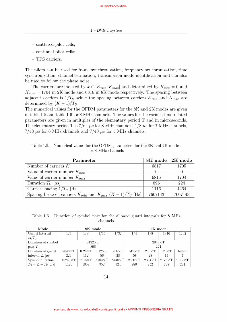
The carriers are indexed by k ∈ [Kmin; Kmax] and determined by Kmin = 0 andKmax = 1704 in 2K mode and 6816 in 8K mode respectively. The spacing betweenadjacent carriers is 1/TU while the spacing between carriers Kmin and Kmax aredetermined by (K − 1)/TU .
The numerical values for the OFDM parameters for the 8K and 2K modes are givenin table 1.5 and table 1.6 for 8 MHz channels. The values for the various time-relatedparameters are given in multiples of the elementary period T and in microseconds.The elementary period T is 7/64 µs for 8 MHz channels, 1/8 µs for 7 MHz channels,7/48 µs for 6 MHz channels and 7/40 µs for 5 MHz channels.
Table 1.5. Numerical values for the OFDM parameters for the 8K and 2K modesfor 8 MHz channels
Parameter 8K mode 2K modeNumber of carriers K 6817 1705Value of carrier number Kmin 0 0Value of carrier number Kmax 6816 1704Duration TU [µs] 896 224Carrier spacing 1/TU [Hz] 1116 4464Spacing between carriers Kmin and Kmax (K − 1)/TU [Hz] 7607143 7607143
Table 1.6. Duration of symbol part for the allowed guard intervals for 8 MHzchannels
Mode 8K mode 2K modeGuard Interval 1/4 1/8 1/16 1/32 1/4 1/8 1/16 1/32∆/TU
Duration of symbol 8192×T 2048×Tpart TU 896 224Duration of guard 2048×T 1024×T 512×T 256×T 512×T 256×T 128×T 64×Tinterval ∆ [µs] 224 112 56 28 56 28 14 7Symbol duration 10240×T 9216×T 8704×T 8448×T 2560×T 2304×T 2176×T 2112×TTS = ∆ + TU [µs] 1120 1008 952 924 280 252 238 231
14
© Gianfranco Miele
scaricato da www.riccardogalletti.com/appunti_gratis - APPUNTI INGEGNERIA GRATIS
1.4 – OFDM frame structure
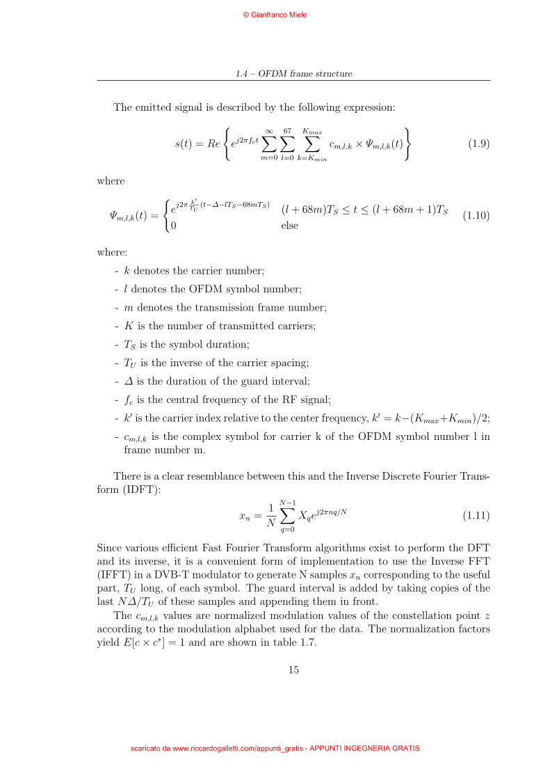
The emitted signal is described by the following expression:
s(t) = Re
{ej2πfct
∞∑m=0
67∑l=0
Kmax∑k=Kmin
cm,l,k × Ψm,l,k(t)
}(1.9)
where
Ψm,l,k(t) =
{e
j2π k′TU
(t−∆−lTS−68mTS)(l + 68m)TS ≤ t ≤ (l + 68m + 1)TS
0 else(1.10)
where:
- k denotes the carrier number;
- l denotes the OFDM symbol number;
- m denotes the transmission frame number;
- K is the number of transmitted carriers;
- TS is the symbol duration;
- TU is the inverse of the carrier spacing;
- ∆ is the duration of the guard interval;
- fc is the central frequency of the RF signal;
- k′ is the carrier index relative to the center frequency, k′ = k−(Kmax+Kmin)/2;
- cm,l,k is the complex symbol for carrier k of the OFDM symbol number l inframe number m.
There is a clear resemblance between this and the Inverse Discrete Fourier Trans-form (IDFT):
xn =1
N
N−1∑q=0
Xqej2πnq/N (1.11)
Since various efficient Fast Fourier Transform algorithms exist to perform the DFTand its inverse, it is a convenient form of implementation to use the Inverse FFT(IFFT) in a DVB-T modulator to generate N samples xn corresponding to the usefulpart, TU long, of each symbol. The guard interval is added by taking copies of thelast N∆/TU of these samples and appending them in front.
The cm,l,k values are normalized modulation values of the constellation point zaccording to the modulation alphabet used for the data. The normalization factorsyield E[c× c∗] = 1 and are shown in table 1.7.
15
© Gianfranco Miele
scaricato da www.riccardogalletti.com/appunti_gratis - APPUNTI INGEGNERIA GRATIS

1 – DVB-T system
Table 1.7. Normalization factor for data symbols
Modulation scheme Normalization factor
QPSK c = z/ 2√
2
16-QAM α = 1 c = z/ 2√
10
α = 2 c = z/ 2√
20
α = 4 c = z/ 2√
52
64-QAM α = 1 c = z/ 2√
42
α = 2 c = z/ 2√
60
α = 4 c = z/ 2√
108
1.5 Reference signals
Various cells within the OFDM frame are modulated with reference informationwhose transmitted value is known to the receiver. Cells containing reference infor-mation are transmitted at “boosted” power level, i.e. E[c× c∗] = 16/9. These cellsare scattered or continual pilot cells.
Each continual pilot coincides with a scattered pilot every fourth symbol; thenumber of useful data carriers is constant from symbol to symbol: 1512 useful car-riers in 2K mode and 6048 useful carriers in 8K mode. The continual and scatteredpilots are modulated according to a Pseudo Random Binary Sequence (PRBS), wk,corresponding to their respective carrier index k. This sequence is generated inaccording to figure 1.10.
Figure 1.10. Generation of PRBS sequence
The PRBS is initialized so that the first output bit from the PRBS coincideswith the first active carrier. A new value is generated by the PRBS on every usedcarrier (whether or not it is a pilot).
16
© Gianfranco Miele
scaricato da www.riccardogalletti.com/appunti_gratis - APPUNTI INGEGNERIA GRATIS
1.5 – Reference signals
The polynomial for the Pseudo Random Binary Sequence (PRBS) generator shallbe:
X11 + X2 + 1. (1.12)
1.5.1 Location of scattered pilot cells
As said previous, scattered pilot cells are always transmitted at the “boosted” powerlevel. Thus the corresponding modulation is given by:
Re {cm,l,k} = 4/3× 2(1/2− wk)Im {cm,l,k} = 0
(1.13)
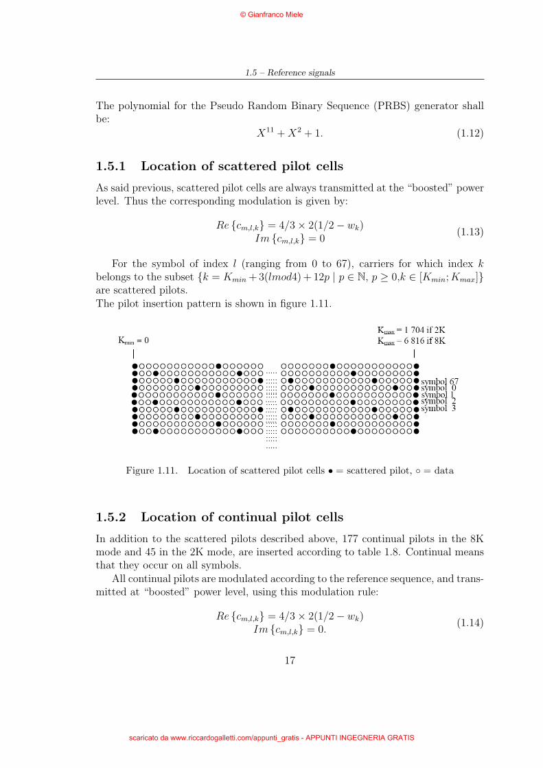
For the symbol of index l (ranging from 0 to 67), carriers for which index kbelongs to the subset {k = Kmin + 3(lmod4) + 12p | p ∈ N, p ≥ 0,k ∈ [Kmin; Kmax]}are scattered pilots.The pilot insertion pattern is shown in figure 1.11.
Figure 1.11. Location of scattered pilot cells • = scattered pilot, ◦ = data
1.5.2 Location of continual pilot cells
In addition to the scattered pilots described above, 177 continual pilots in the 8Kmode and 45 in the 2K mode, are inserted according to table 1.8. Continual meansthat they occur on all symbols.
All continual pilots are modulated according to the reference sequence, and trans-mitted at “boosted” power level, using this modulation rule:
Re {cm,l,k} = 4/3× 2(1/2− wk)Im {cm,l,k} = 0.
(1.14)
17
© Gianfranco Miele
scaricato da www.riccardogalletti.com/appunti_gratis - APPUNTI INGEGNERIA GRATIS

1 – DVB-T system
Table 1.8. Carrier indices for continual pilot carriers
2K mode 8K mode0 48 54 87 141 156 192 0 48 54 87 141 156 192
201 255 279 282 333 432 450 201 255 279 282 333 432 450483 525 531 618 636 714 759 483 525 531 618 636 714 759942 969 984 1050 1101 1107 1110 942 969 984 1050 1101 1107 11101137 1140 1146 1206 1269 1323 1377 1137 1140 1146 1206 1269 1323 13771491 1683 1704 1491 1683 1704 1752 1758 1791 1845
1860 1896 1905 1959 1983 1986 20372136 2154 2187 2229 2235 2322 23402418 2463 2469 2484 2508 2577 25922622 2643 2646 2673 2688 2754 28052811 2814 2841 2844 2850 2910 29733027 3081 3195 3387 3408 3456 34623495 3549 3564 3600 3609 3663 36873690 3741 3840 3858 3891 3933 39394026 4044 4122 4167 4173 4188 42124281 4296 4326 4347 4350 4377 43924458 4509 4515 4518 4545 4548 45544614 4677 4731 4785 4899 5091 51125160 5166 5199 5253 5268 5304 53135367 5391 5394 5445 5544 5562 55955637 5643 5730 5748 5826 5871 58775892 5916 5985 6000 6030 6051 60546081 6096 6162 6213 6219 6222 62496252 6258 6318 6381 6435 6489 66036795 6816
1.6 Transmission Parameter Signalling (TPS)
The TPS carriers are used for the purpose of signalling parameters related to thetransmission scheme, i.e. to channel coding and modulation. The TPS is trans-mitted in parallel on 17 TPS carriers for the 2K mode and on 68 carriers for the8K mode. Every TPS carrier in the same symbol conveys the same differentiallyencoded information bit. The carrier indices containing TPS carriers are listed intable 1.9.
The TPS is defined over 68 consecutive OFDM symbols, referred to as one OFDMframe. The reference sequence corresponding to the TPS carriers of the first symbolof each OFDM frame are used to initialize the TPS modulation on each TPS carrier.Each OFDM symbol conveys one TPS bit. Each TPS block (corresponding to oneOFDM frame) contains 68 bits, defined as follows:
- 1 initialization bit;
- 16 synchronization bits;
18
© Gianfranco Miele
scaricato da www.riccardogalletti.com/appunti_gratis - APPUNTI INGEGNERIA GRATIS

1.6 – Transmission Parameter Signalling (TPS)
Table 1.9. Carrier indices for TPS carriers
2K mode 8K mode34 50 209 346 413 34 50 209 346 413 569 595569 595 688 790 901 688 790 901 1073 1219 1262 12861073 1219 1262 1286 1469 1469 1594 1687 1738 1754 1913 20501594 1687 2117 2273 2299 2392 2494 2605 2777
2923 2966 2990 3173 3298 3391 34423458 3617 3754 3821 3977 4003 40964198 4309 4481 4627 4670 4694 48775002 5095 5146 5162 5321 5458 55255681 5707 5800 5902 6013 6185 63316374 6398 6581 6706 6799
- 37 information bits;
- 14 redundancy bits for error protection.
Of the 37 information bits, 31 are used. The remaining 6 bits shall be set to zero.
1.6.1 TPS transmission format
The transmission parameter information shall be transmitted as shown in table 1.10.
Table 1.10. TPS signalling information and format
Bit number Purpose/Contents0 Initialization
s1 to s16 Synchronization words17 to s22 Length indicator (see appendix A)s23, s24 Frame numbers25, s26 Constellation
s27, s28, s29 Hierarchy information (see appendix A)s30, s31, s32 Code rate, HP streams33, s34, s35 Code rate, LP stream
s36, s37 Guard intervals38, s39 Transmission mode (see appendix A)
s40 to s47 Cell identifiers48 to s53 all set to “0” see appendix As54 to s67 Error protection
19
© Gianfranco Miele
scaricato da www.riccardogalletti.com/appunti_gratis - APPUNTI INGEGNERIA GRATIS
1 – DVB-T system
The TPS information transmitted in super-frame m′ bits s25-s39 always apply tosuper-frame m′ + 1, whereas all other bits refer to super-frame m′.
Initialization
The first bit, s0, is an initialization bit for the differential 2-PSK modulation.
Synchronization
Bits 1 to 16 of TPS makes a synchronization word.The first and third TPS block in each super-frame have the following synchronizationword:
s1-s16 = 0011010111101110.
The second and fourth TPS block have the following synchronization word:
s1-s16 = 1100101000010001.
TPS length indicator
The first 6 bits of the TPS information are used as a TPS length indicator (is thebinary count of TPS information bits starting from and including bit s17 to s47) tosignal the number of used bits of the TPS.This field is indispensable beacuse in DVB-T the transmission of the Cell Identifi-cation is optional. The TPS length indicator carries then the values:
- “010111” when Cell Identification information is not transmitted (23 TPS bitsin use);
- “011111” when Cell Identification information is transmitted (31 TPS bits inuse).
Frame number
As said previous, 4 frames constitute one super-frame and the frames inside thesuper-frame are numbered from 1 to 4. For this reason a 2 bits field in TPS blockis used to transmit the frame number as specified in table 1.11.
Constellation
The constellation shall be signalled by 2 bits field according to table 1.12. In orderto determine the modulation scheme, the receiver shall also decode the hierarchyinformation given in table 1.13.
20
© Gianfranco Miele
scaricato da www.riccardogalletti.com/appunti_gratis - APPUNTI INGEGNERIA GRATIS

1.6 – Transmission Parameter Signalling (TPS)
Table 1.11. Signalling format for frame number
Bits s23, s24 Frame number00 Frame number 1 in the super-frame01 Frame number 2 in the super-frame10 Frame number 3 in the super-frame11 Frame number 4 in the super-frame
Table 1.12. Signalling format for the possible constellation patterns
Bits s25, s26 Constellation characteristics00 QPSK01 16-QAM10 64-QAM11 Reserved
Hierarchy information
The hierarchy information specifies whether the transmission is hierarchical and, ifso, what the α value is used. These information are signalled by three bits accordingto table 1.13.
Table 1.13. Signalling format for the α values
Bits s27, s28, s29 α value000 Non-hierarchical001 α = 1010 α = 2011 α = 4100 See appendix A101 See appendix A110 See appendix A111 See appendix A
Code rates
HP stream and LP stream code rates are transmitted using the six bits from s30
to s35 in according to table 1.14. In case of non-hierarchical channel coding andmodulation requires signalling of one code rate r. In this case, three bits specifying
21
© Gianfranco Miele
scaricato da www.riccardogalletti.com/appunti_gratis - APPUNTI INGEGNERIA GRATIS
1 – DVB-T system
the code rate as shown in table 1.14 are followed by another three bits of value 000.
Table 1.14. Signalling format for each of the code rates
Bits Code rates30, s31, s32 (HP stream)s33, s34, s35 (LP stream)
000 1/2001 2/3010 3/4011 5/6100 7/8101 reserved110 reserved111 reserved
Guard intervals
The value of the guard interval is signalled according to table 1.15.
Table 1.15. Signalling format for each of the guard interval values
Bits s36, s37 Guard interval values (∆/TU)00 1/3201 1/1610 1/811 1/4
Transmission mode
Two bits are used to signal the transmission mode (2K mode or 8K mode).
Cell identifier
The eight bits s40-s47 are used to identify the cell from which the signal comes from.The most significant byte of the cell id, i.e. b15-b8, shall be transmitted in super-frames with the frame number 1 and 3. The least significant byte of the cell id, i.e.b7-b0, shall be transmitted in super-frames with the frame number 2 and 4. The
22
© Gianfranco Miele
scaricato da www.riccardogalletti.com/appunti_gratis - APPUNTI INGEGNERIA GRATIS
1.6 – Transmission Parameter Signalling (TPS)
Table 1.16. Signalling format for transmission mode
Bits s38, s39 Transmission mode00 2K mode01 8K mode10 see appendix A11 reserved
mapping of bits is according to table 1.17. If the transmission of the cell id is notforeseen the eight bits shall be set to zero.
Table 1.17. Mapping of the cell id on the TPS bits
TPS bit number Frame number 1 or 3 Frame number 2 or 4s40 cell id b15 cell id b7
s41 cell id b14 cell id b6
s42 cell id b13 cell id b5
s43 cell id b12 cell id b4
s44 cell id b11 cell id b3
s45 cell id b10 cell id b2
s46 cell id b9 cell id b1
s47 cell id b8 cell id b0
Error protection of TPS
The 53 bits containing the TPS synchronization and information (bits s1-s53) areextended with 14 parity bits of the BCH(67,53,t = 2) shortened code, derived fromthe original systematic BCH(127,113,t = 2) code. The code generator polynomialis:
h(x) = x14 + x9 + x8 + x6 + x5 + x4 + x2 + x + 1. (1.15)
The shortened BCH code may be implemented by adding 60 bits, all set to zero,before the information bits input of an BCH(127,113,t = 2) encoder. After the BCHencoding these null bits shall be discarded, leading to a BCH code word of 67 bits.
1.6.2 TPS modulation
As said previous, every TPS carrier is DBPSK modulated and conveys the samemessage. The DBPSK is initialized at the beginning of each TPS block.
23
© Gianfranco Miele
scaricato da www.riccardogalletti.com/appunti_gratis - APPUNTI INGEGNERIA GRATIS
1 – DVB-T system
The rule used for differential modulation of the carrier k of the OFDM symbol l(l > 0) in frame m is:
Re {cm,l,k} = Re {cm,l−1,k} ; Im {cm,l,k} if sl=0Re {cm,l,k} = −Re {cm,l−1,k} ; Im {cm,l,k} if sl=1
(1.16)
The absolute modulation of the TPS carriers in the first symbol in a frame is derivedfrom the reference sequence wk as follows:
Re {cm,l,k} = 2(1/2− wk)Im {cm,l,k} = 0
(1.17)
1.7 DVB-T system parameter summary and net
data rate
In summary, the following parameters can be chosen in the DVB-T system:
- code rate of inner error protection(1/2, 2/3, 3/4, 5/6, 7/8);
- carrier modulation (QPSK ⇒ 2 bits per carrier; 16-QAM ⇒ 4 bits; 64-QAM⇒ 6 bits);
- guard interval length (1/4, 1/8, 1/16, 1/32);
- modulation parameter α (1, 2, 4);
- FFT length; number of carriers (2k ⇒ 1705 carriers; 8k ⇒ 6817 carriers).
The net bit rate depends on the code rate of the inner error correction, themethod of the carrier modulation and the chosen guard interval length. In table 1.18is summarized all possible net data rates in the DVB-T system. The net date ratesare calculated from the following formula [6]:
RU = RS × v × CRI × CRRS × (TU/TS) (1.18)
where:
- RU is the useful net data rate (Mbit/s);
- RS is the symbol rate, 6.75 Msymbols/s;
- v is the number of bit per carrier;
- CRI is the inner code rate;
- CRRS is the Reed Solomon code rate, 188/204;
- TU is the duration of (useful) symbol part;
- TS is the symbol duration, including guard interval.
24
© Gianfranco Miele
scaricato da www.riccardogalletti.com/appunti_gratis - APPUNTI INGEGNERIA GRATIS

1.8 – Spectrum characteristics
Table 1.18. Net data rates in the DVB-T system (in Mbit/s)
∆/TU
Modulation v CRI 1/4 1/8 1/16 1/32QPSK 2 1/2 4.98 5.53 5.85 6.03
2 2/3 6.64 7.37 7.81 8.042 3/4 7.46 8.29 8.78 9.052 5/6 8.29 9.22 9.76 10.052 7/8 8.71 9.68 10.25 10.56
16-QAM 4 1/2 9.95 11.06 11.71 12.064 2/3 13.27 14.75 15.61 16.094 3/4 14.93 16.59 17.56 18.104 5/6 16.59 18.43 19.52 20.114 7/8 17.42 19.35 20.49 21.11
64-QAM 6 1/2 14.93 16.59 17.56 18.106 2/3 19.91 22.12 23.42 24.136 3/4 22.39 24.88 26.35 27.146 5/6 24.88 27.65 29.27 30.166 7/8 26.13 29.03 30.74 31.67
1.8 Spectrum characteristics
The OFDM symbols are constituted by a juxtaposition of equally-spaced orthogonalcarriers. The amplitudes and phases of the data cell carriers are varying symbol bysymbol according to the mapping process described previous.
Each carrier is situated at frequency:
fk = fc +k
TU
; (1.19)
and has a power spectral density Pk(f) defined by the following expression:
Pk(f) =
[sin π(f − fk)TS
π(f − fk)TS
]2
. (1.20)
The overall power spectral density (PSD) of the modulated data cell carriers isthe sum of the power spectral densities of all these carriers. A theoretical DVBtransmission signal spectrum is illustrated in figure 1.12 (for 8 MHz channels).
25
© Gianfranco Miele
scaricato da www.riccardogalletti.com/appunti_gratis - APPUNTI INGEGNERIA GRATIS

1 – DVB-T system
Figure 1.12. Theoretical DVB transmission signal spectrum for guard interval∆ = TU/4 (for 8 MHz channels)
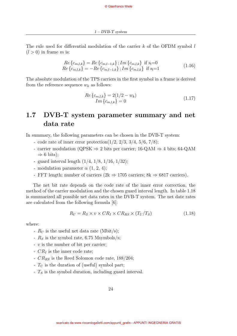
1.9 Time-domain signal characteristics
How it is possible to see in figure 1.13 the DVB-T signal in time-domain exhibits anoise-like characteristic, this is a OFDM signals typical feature. In general this kindof signals present high crest factor cf and DVB-T signal isn’t an exception [3]. Thecrest factor is defined as:
cf = 20log10
(U
U
)(1.21)
where U is the maximum peak voltage and U is the root mean square rms voltage.
Because the OFDM signals is composed by a sum of modulated signals, themaximum peak voltage is obtained by adding together the peak amplitudes of allsingle carriers:
U =N−1∑k=0
Uk (1.22)
where N is the total number of modulated carriers in a OFDM symbol, and Uk isthe maximum peak voltage of the carrier k. If all carriers have the same maximum
26
© Gianfranco Miele
scaricato da www.riccardogalletti.com/appunti_gratis - APPUNTI INGEGNERIA GRATIS
1.9 – Time-domain signal characteristics
Figure 1.13. Time-domain DVB-T signal for guard interval ∆ = TU/4 and 64-QAM modulation scheme
peak voltage, i.e. QPSK, the relation 1.22 becomes:
U = NU0. (1.23)
In the same manner, the rms value of an OFDM signal is calculated from thequadratic mean as:
U = 2
√√√√N−1∑k=0
Uk2
(1.24)
where Uk is the rms value of the carrier k of a OFDM symbol. If all carriers havethe same maximum peak voltage, i.e. QPSK, the relation 1.24 can be written as:
U =2
√NU0
2=
2
√N
U02
2. (1.25)
After these considerations, the cf of a OFDM signal is
cf = 20log10
NU0
2
√N U0
2
2
= 20log10
(2√
2N)
= 10log10 (2N) . (1.26)
27
© Gianfranco Miele
scaricato da www.riccardogalletti.com/appunti_gratis - APPUNTI INGEGNERIA GRATIS
1 – DVB-T system
The theoretical cf in DVB-T are then
cf =
{35 dB in 2K mode with 1705 carries used
41 dB in 8K mode with 6817 carries used.(1.27)
Even though the theoretical cf is very high, the cf of a real DVB-T signal is limitedto about 11-12 dB before the signal is fed into the power amplifier. This limitation isnecessary because any practical power amplifier can’t operate with high cf withoutcausing its destruction.
28
© Gianfranco Miele
scaricato da www.riccardogalletti.com/appunti_gratis - APPUNTI INGEGNERIA GRATIS

Appendix A
Additional features for DVBHandheld terminals (DVB-H)
A.1 Introduction
Although the DVB-T transmission system has proven its ability to serve fixed,portable and mobile terminals, handheld terminals (defined as a light battery pow-ered apparatus) require specific features from the transmission system serving them:
• as battery powered, the transmission system shall offer them the possibility torepeatedly power off some part of the reception chain to increase the batteryusage duration;
• as targeting nomadic users, the transmission system shall ease access to theDVB-H services when receivers leave a given transmission cell and enter a newone;
• as expected to serve various situations of use (indoor and outdoor, pedestrianand inside moving vehicle), the transmission system shall offer sufficient flex-ibility / scalability to allow reception of DVB-H services at various speeds,while optimizing transmitter coverage.
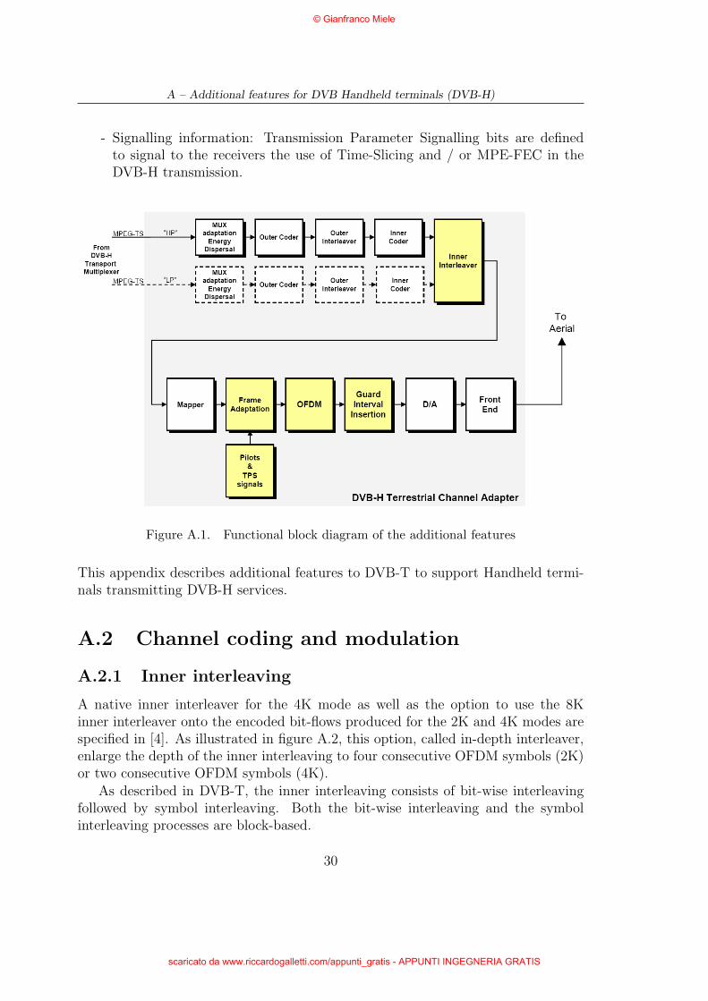
To overcome these problems the following processes variant are implemented, asdepicted in figure A.1:
- Orthogonal Frequency Division Multiplexing (OFDM) transmission: an addi-tional 4K mode is provided with the implied reference signals and TransmissionParameter Signalling (TPS);
- Inner interleaving: a native inner interleaver for the 4K transmission modeis provided as well as an in-depth symbol interleaver to be used with the 2Kor 4K modes. Also, the implied Transmission Parameter Signalling (TPS) isdefined;
29
© Gianfranco Miele
scaricato da www.riccardogalletti.com/appunti_gratis - APPUNTI INGEGNERIA GRATIS
A – Additional features for DVB Handheld terminals (DVB-H)
- Signalling information: Transmission Parameter Signalling bits are definedto signal to the receivers the use of Time-Slicing and / or MPE-FEC in theDVB-H transmission.
Figure A.1. Functional block diagram of the additional features
This appendix describes additional features to DVB-T to support Handheld termi-nals transmitting DVB-H services.
A.2 Channel coding and modulation
A.2.1 Inner interleaving
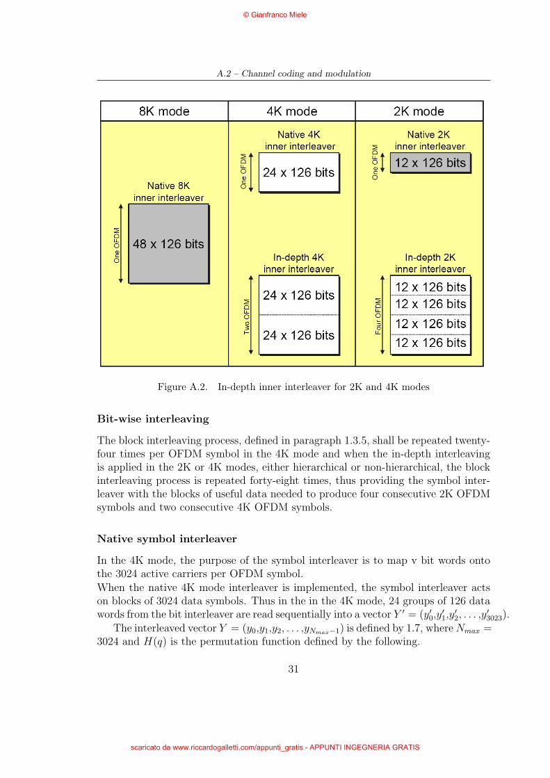
A native inner interleaver for the 4K mode as well as the option to use the 8Kinner interleaver onto the encoded bit-flows produced for the 2K and 4K modes arespecified in [4]. As illustrated in figure A.2, this option, called in-depth interleaver,enlarge the depth of the inner interleaving to four consecutive OFDM symbols (2K)or two consecutive OFDM symbols (4K).
As described in DVB-T, the inner interleaving consists of bit-wise interleavingfollowed by symbol interleaving. Both the bit-wise interleaving and the symbolinterleaving processes are block-based.
30
© Gianfranco Miele
scaricato da www.riccardogalletti.com/appunti_gratis - APPUNTI INGEGNERIA GRATIS
A.2 – Channel coding and modulation
Figure A.2. In-depth inner interleaver for 2K and 4K modes
Bit-wise interleaving
The block interleaving process, defined in paragraph 1.3.5, shall be repeated twenty-four times per OFDM symbol in the 4K mode and when the in-depth interleavingis applied in the 2K or 4K modes, either hierarchical or non-hierarchical, the blockinterleaving process is repeated forty-eight times, thus providing the symbol inter-leaver with the blocks of useful data needed to produce four consecutive 2K OFDMsymbols and two consecutive 4K OFDM symbols.
Native symbol interleaver
In the 4K mode, the purpose of the symbol interleaver is to map v bit words ontothe 3024 active carriers per OFDM symbol.When the native 4K mode interleaver is implemented, the symbol interleaver actson blocks of 3024 data symbols. Thus in the in the 4K mode, 24 groups of 126 datawords from the bit interleaver are read sequentially into a vector Y ′ = (y′0,y
′1,y
′2, . . . ,y
′3023).
The interleaved vector Y = (y0,y1,y2, . . . ,yNmax−1) is defined by 1.7, where Nmax =3024 and H(q) is the permutation function defined by the following.
31
© Gianfranco Miele
scaricato da www.riccardogalletti.com/appunti_gratis - APPUNTI INGEGNERIA GRATIS
A – Additional features for DVB Handheld terminals (DVB-H)
Let an (Nr − 1) bit binary word R′i is defined, with Nr = log2Mmax, where
Mmax = 4196, taking the following values: a vector Ri is derived by the vector R′i
i = 0,1: R′i[Nr − 2,Nr − 3, · · · ,1,0] = 0,0, · · · ,0,0
i = 2: R′i[Nr − 2,Nr − 3, · · · ,1,0] = 0,0, · · · ,0,1
2 < i < Mmax {R′i[Nr − 3,Nr − 3, · · · ,1,0] = R′
i−1[Nr − 2,Nr − 3, · · · ,2,1]in the 4K mode: R′
i[10] = R′i−1[0]⊕R′
i−1[2]
by the it permutation defined in table A.1. The algorithm used to generate the
Table A.1. Bit permutations for 4K mode
R′i bit positions 10 9 8 7 6 5 4 3 2 1 0
Ri bit positions 7 10 5 8 1 2 4 9 0 3 6
permutation function is the same described in paragraph 1.3.5.
In-depth symbol interleavers
When the in-depth interleaver is selected in the 2K mode or 4K mode contexts, thesymbol interleaver acts on blocks of 6048 data symbols, whatever the mode. Thus,a vector Y ′ = (y′0,y
′1,y
′2, . . . ,y
′6047) is assembled from 48 groups of 126 data words.
The interleaved vector Y = (y0,y1,y2, . . . ,yNmax−1) is defined by:
yH(q) = y′q for even interleaved vectors for q = 0, . . . ,Nmax − 1yq = y′H(q) for odd interleaved vectors for q = 0, . . . ,Nmax − 1
(A.1)
where Nmax = 6048 in the 2K mode and Nmax = 6048 in the 8K mode, and H(q) isthe permutation function defined for native 8K mode in paragraph 1.3.5.
In the 2K mode, interleaved vectors shall be mapped onto four consecutiveOFDM symbols. For even interleaved vectors these shall start with symbols 0,8, 16, 24, etc. and for odd interleaved vectors these shall start with symbols 4, 12,20, 28, etc. in every super-frame.
In the 4K mode, interleaved vectors shall be mapped onto two consecutive OFDMsymbols. For even interleaved vectors these shall start with symbols 0, 4, 8, 12, etc.and for odd interleaved vectors these shall start with symbols 2, 6, 10, 14, etc. inevery super-frame.
32
© Gianfranco Miele
scaricato da www.riccardogalletti.com/appunti_gratis - APPUNTI INGEGNERIA GRATIS
A.3 – OFDM frame structure
A.3 OFDM frame structure
For the 4K mode, each symbol is constituted by a set of K = 3409 carriers andtransmitted with a duration TS. It is composed of two parts: a useful part withduration TU and a guard interval with duration ∆. The guard interval consists in acyclic continuation of the useful part, TU , and is inserted before it. Four values ofguard intervals may be used according to table A.3. For the 4K mode, the carriersare indexed by k ∈ [Kmin; Kmax] and determined by Kmin = 0 and Kmax = 3408.For the 4K mode, the numerical values for the OFDM parameters in 8 MHz channelare given in table A.2 and table A.3.
Table A.2. Numerical values for the OFDM parameters for the 4K mode for8 MHz channels
Parameter 4K modeNumber of carriers K 3409Value of carrier number Kmin 0Value of carrier number Kmax 3408Duration TU [µs] 448Carrier spacing 1/TU [Hz] 2232Spacing between carriers Kmin and Kmax (K − 1)/TU [Hz] 7607143
Table A.3. Duration of symbol part for the allowed guard intervals for 8 MHzchannels
Mode 4K modeGuard Interval 1/4 1/8 1/16 1/32∆/TU
Duration of symbol 8192×Tpart TU 896Duration of guard 1024×T 512×T 256×T 128×Tinterval ∆ [µs] 112 56 28 14Symbol duration 5120×T 4608×T 4352×T 4224×TTS = ∆ + TU [µs] 560 504 476 462
A.4 Reference signals
A.4.1 Location of continual pilot carriers
For the 4K mode, 89 continual pilots shall be inserted according to table A.4.
33
© Gianfranco Miele
scaricato da www.riccardogalletti.com/appunti_gratis - APPUNTI INGEGNERIA GRATIS

A – Additional features for DVB Handheld terminals (DVB-H)
Table A.4. Carrier indices for continual pilot carriers
Continual pilots carrier positions for 4K mode0 48 54 87 141 156 192
201 255 279 282 333 432 450483 525 531 618 636 714 759942 969 984 1050 1101 1107 11101137 1140 1146 1206 1269 1323 13771491 1683 1704 1752 1758 1791 18451860 1896 1905 1959 1983 1986 20372136 2154 2187 2229 2235 2322 23402418 2463 2469 2484 2508 2577 25922622 2643 2646 2673 2688 2754 28052811 2814 2841 2844 2850 2910 29733027 3081 3195 3387 3408
A.5 Transmission Parameter Signalling (TPS)
For the 4K mode, the TPS shall be transmitted in parallel on 34 TPS carriers andshall be carried on the carrier having the indices presented in table A.5.
Table A.5. Carrier indices for TPS carriers
TPS carrier indices for 4K mode34 50 209 346 413 569 595688 790 901 1073 1219 1262 12861469 1594 1687 1738 1754 1913 20502117 2273 2299 2392 2494 2605 27772923 2966 2990 3173 3298 3391
A.5.1 TPS transmission format
When DVB-H signalling is performed, of the 37 information bits, 33 are used. Theremaining 4 bits shall be set to zero.
Options shown in table A.6 are specified in this appendix. The definitions forthe other signalling bits are given in the paragraph 1.6.
TPS length indicator
In DVB-H signal valid Cell Identification information shall be transmitted and thevalue of the TPS length indicator shall be set to “100001” (33 TPS bits in use).
34
© Gianfranco Miele
scaricato da www.riccardogalletti.com/appunti_gratis - APPUNTI INGEGNERIA GRATIS
A.5 – Transmission Parameter Signalling (TPS)
Table A.6. TPS signalling information and format
Bit number Purpose/Contents17 to s22 Length indicator
s27, s28, s29 Hierarchy and Interleaving informations38, s39 Transmission mode
s48 to s49 DVB-H signallings50 to s53 all set to “0”
Hierarchy and Interleaving information
The bits s27, s28, s29 are used to signal if the in-depth interleaver is in use and if thetransmission is hierarchical.
The use of the in-depth interleaver for 2K or 4K transmission mode shall be signalledusing bit s27 as indicated in table A.7. When an 8K signal is transmitted only thenative interleaver shall be used.
Table A.7. Signalling format for in-depth inner interleaver
Bit s27 In-depth inner interleaver information0 native interleaver1 in-depth interleaver
Hierarchical transmission and, if so, the value of the α factor shall be signalled,using bits s28 and s29, in compliance with table A.8.
Table A.8. Signalling format for Hierarchy information
Bits s28, s29 Hierarchy information00 Non-hierarchical01 α = 110 α = 211 α = 4
Transmission mode
The transmission mode shall be signalled according to table A.9.
35
© Gianfranco Miele
scaricato da www.riccardogalletti.com/appunti_gratis - APPUNTI INGEGNERIA GRATIS

A – Additional features for DVB Handheld terminals (DVB-H)
Table A.9. Signalling format for transmission mode
Bits s38, s39 Transmission mode00 2K mode01 8K mode10 4K mode11 reserved
DVB-H signalling
Bits s48 and s49 shall be used to indicate to the receivers the transmission of DVB-Hservices in compliance with table A.10.In case of hierarchical transmission, the signification of these bits varies with theparity of the OFDM frame transmitted, as follows:
- when received during OFDM frame number 1 and 3 of each super frame, DVB-H signalling shall be interpreted as in relation with the High Priority stream(HP);
- when received during OFDM frame number 2 and 4 of each super frame, DVB-H signalling shall be interpreted as in relation with the Low Priority stream(LP).
In case of non-hierarchical transmission, every frame in the super-frame carries thesame information.
Table A.10. DVB-H service indication
s48 s49 Transmission mode0 x Time Slicing is not used1 x At least one elementary stream uses Time Slicingx 0 MPE-FEC not usedx 1 At least one elementary stream uses MPE-FEC
NOTE: “x” means whatever bit state.
36
© Gianfranco Miele
scaricato da www.riccardogalletti.com/appunti_gratis - APPUNTI INGEGNERIA GRATIS
Bibliography
[1] ETSI EN 300 421: “Digital Video Broadcasting (DVB); Framing structure,channel coding and modulation for 11/12 GHz satellite services (V1.1.2)”. Au-gust 1997.
[2] ETSI EN 300 429: “Digital Video Broadcasting (DVB); Framing structure,channel coding and modulation for cable systems (V1.2.1)”. April 1998.
[3] W. Fischer, Digital Television - A Pratical Guide for Engineers. Springer-Verlag,2004.
[4] ETSI EN 300 744: “Digital Video Broadcasting (DVB); Framing structure,channel coding and modulation for digital terrestrial television (V1.5.1)”.November 2004.
[5] ISO/IEC 13818 (Parts 1 to 3): “Information technology - Generic coding ofmoving pictures and associated audio information”. 1998.
[6] ETSI TR 101 190: “Digital Video Broadcasting (DVB); Implementation guide-lines for DVB terrestrial services; Transmission aspects (V1.2.1)”. November2004.
37
© Gianfranco Miele
scaricato da www.riccardogalletti.com/appunti_gratis - APPUNTI INGEGNERIA GRATIS
List of Tables
List of Tables
1.1 Puncturing pattern and transmitted sequence after parallel-to-serialconversion for the possible code rates . . . . . . . . . . . . . . . . . . 7
1.2 Bit-wise interleaver permutation function . . . . . . . . . . . . . . . . 101.3 Bit permutations for 2K mode . . . . . . . . . . . . . . . . . . . . . . 101.4 Bit permutations for 8K mode . . . . . . . . . . . . . . . . . . . . . . 111.5 Numerical values for the OFDM parameters for the 8K and 2K modes
for 8 MHz channels . . . . . . . . . . . . . . . . . . . . . . . . . . . . 141.6 Duration of symbol part for the allowed guard intervals for 8 MHz
channels . . . . . . . . . . . . . . . . . . . . . . . . . . . . . . . . . . 141.7 Normalization factor for data symbols . . . . . . . . . . . . . . . . . . 161.8 Carrier indices for continual pilot carriers . . . . . . . . . . . . . . . . 181.9 Carrier indices for TPS carriers . . . . . . . . . . . . . . . . . . . . . 191.10 TPS signalling information and format . . . . . . . . . . . . . . . . . 191.11 Signalling format for frame number . . . . . . . . . . . . . . . . . . . 211.12 Signalling format for the possible constellation patterns . . . . . . . . 211.13 Signalling format for the α values . . . . . . . . . . . . . . . . . . . . 211.14 Signalling format for each of the code rates . . . . . . . . . . . . . . . 221.15 Signalling format for each of the guard interval values . . . . . . . . . 221.16 Signalling format for transmission mode . . . . . . . . . . . . . . . . 231.17 Mapping of the cell id on the TPS bits . . . . . . . . . . . . . . . . . 231.18 Net data rates in the DVB-T system (in Mbit/s) . . . . . . . . . . . . 25
A.1 Bit permutations for 4K mode . . . . . . . . . . . . . . . . . . . . . . 32A.2 Numerical values for the OFDM parameters for the 4K mode for
8 MHz channels . . . . . . . . . . . . . . . . . . . . . . . . . . . . . . 33A.3 Duration of symbol part for the allowed guard intervals for 8 MHz
channels . . . . . . . . . . . . . . . . . . . . . . . . . . . . . . . . . . 33A.4 Carrier indices for continual pilot carriers . . . . . . . . . . . . . . . . 34A.5 Carrier indices for TPS carriers . . . . . . . . . . . . . . . . . . . . . 34A.6 TPS signalling information and format . . . . . . . . . . . . . . . . . 35A.7 Signalling format for in-depth inner interleaver . . . . . . . . . . . . . 35
38
© Gianfranco Miele
scaricato da www.riccardogalletti.com/appunti_gratis - APPUNTI INGEGNERIA GRATIS
List of Tables
A.8 Signalling format for Hierarchy information . . . . . . . . . . . . . . . 35A.9 Signalling format for transmission mode . . . . . . . . . . . . . . . . 36A.10 DVB-H service indication . . . . . . . . . . . . . . . . . . . . . . . . 36
39
© Gianfranco Miele
scaricato da www.riccardogalletti.com/appunti_gratis - APPUNTI INGEGNERIA GRATIS

List of Figures
List of Figures
1.1 Functional block diagram of a DVB-T transmitter . . . . . . . . . . . 31.2 MPEG-2 transport multiplexer packet . . . . . . . . . . . . . . . . . 41.3 Scrambler/descrambler schematic diagram . . . . . . . . . . . . . . . 51.4 Randomized transport packets . . . . . . . . . . . . . . . . . . . . . . 51.5 Reed-Solomon RS(204,188,t = 8) error protected packets . . . . . . . 61.6 Conceptual diagram of the outer interleaver and deinterleaver . . . . 61.7 The mother convolutional code of rate 1/2 . . . . . . . . . . . . . . . 71.8 Inner interleaver: a) non-hierarchical transmission mode, b) hierar-
chical transmission mode . . . . . . . . . . . . . . . . . . . . . . . . . 81.9 Constellation examples: a) uniform 16-QAM or non-uniform 16-QAM
with α = 1, b) non-uniform 16-QAM with α = 2, c) non-uniform 16-QAM with α = 4 . . . . . . . . . . . . . . . . . . . . . . . . . . . . . 12
1.10 Generation of PRBS sequence . . . . . . . . . . . . . . . . . . . . . . 161.11 Location of scattered pilot cells • = scattered pilot, ◦ = data . . . . . 171.12 Theoretical DVB transmission signal spectrum for guard interval ∆ =
TU/4 (for 8 MHz channels) . . . . . . . . . . . . . . . . . . . . . . . . 261.13 Time-domain DVB-T signal for guard interval ∆ = TU/4 and 64-
QAM modulation scheme . . . . . . . . . . . . . . . . . . . . . . . . . 27
A.1 Functional block diagram of the additional features . . . . . . . . . . 30A.2 In-depth inner interleaver for 2K and 4K modes . . . . . . . . . . . . 31
40
© Gianfranco Miele
scaricato da www.riccardogalletti.com/appunti_gratis - APPUNTI INGEGNERIA GRATIS