Installation Manual - faac.co.uk
31
Leading the way ... Installation Manual 950 Leading the way ... Door Automation
Transcript of Installation Manual - faac.co.uk
Leading the way ...
Installation Manual950
Leading the way ...
Door Automation

Fig. 2a
Fig. 2bFig. 3
11 22
3
3
1
2
4
5 Fig. 4 Fig. 4b
Fig. 4a
6
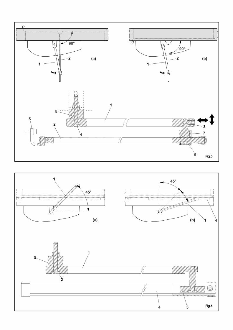
Fig.5
Fig.6

Quota con albero standard.Nel caso fosse necessario aumentarela distanza tra l’operatore ed ilbraccio, utilizzare le prolunghemodulari opzionali.Ciacuna prolunga aumenta il valoredi altezza standard di 30 mm. E’suggeribile non montare più di 2prolunghe .
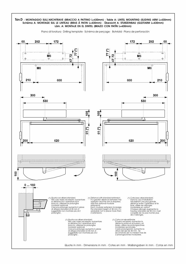
(*) Distance with standard extension.If a greater distance between theoperator and the arm is required,add the optional modularextensions.Each modular extension increasesthe standard height of 30 mm. It’sadvisable not to place more then2 extensions.
(*) Cote avec arbre standard.Dans le cas d’installationnécessitant une plus grandedistance entre l’opérateur et lebras, utiliser les rallongesmodulaires en option.Chaque rallonge augmente lahauteur standard de 30 mm. Il estconseillé de ne pas monter plusde 2 rallonges.
(*)
(*) Cota con eje estándar.Si fuera necesario aumentar ladistancia entre el actuador y elbrazo, utilizar las prolongaciónesmodulares opcionales.Cada prolungación aumenta laaltura del eje de 30 mm. Serecomanda de no instalar mas de2 prolongaciónes modulares.
(*)
Quote in mm · Dimensions in mm · Cotes en mm · Maßangaben in mm · Cotas en mm
Quota con albero standard.Nel caso fosse necessario aumentarela distanza tra l’operatore ed ilbraccio, utilizzare le prolunghemodulari opzionali.Ciacuna prolunga aumenta il valoredi altezza standard di 30 mm. E’suggeribile non montare più di 2prolunghe .
Tav.A: MONTAGGIO SULL’ARCHITRAVE (BRACCIO ARTICOLATO A SPINGERE) · TABLE A: LINTEL MOUNTING (PUSHING ARTICULATED ARM)SCHÉMA A: MONTAGE SUR LE LINTEAU (BRAS ARTICULÉ Á POUSSER) · ÜBERSICHT A: STURZEINBAU (DRÜCK-GELENKARM)
LÁM. A: MONTAJE EN EL DINTEL (BRAZO ARTICULADO DE EMPUJE)
Piano di foratura · Drilling template · Schéma de perçage · Bohrbild · Plano de perforación

Quota con albero standard.Nel caso fosse necessario aumentarela distanza tra l’operatore ed ilbraccio, utilizzare le prolunghemodulari opzionali.Ciacuna prolunga aumenta il valoredi altezza standard di 30 mm. E’suggeribile non montare più di 2prolunghe .
(*) Distance with standard extension.If a greater distance between theoperator and the arm is required,add the optional modularextensions.Each modular extension increasesthe standard height of 30 mm. It’sadvisable not to place more then2 extensions.
(*) Cote avec arbre standard.Dans le cas d’installationnécessitant une plus grandedistance entre l’opérateur et lebras, utiliser les rallongesmodulaires en option.Chaque rallonge augmente lahauteur standard de 30 mm. Il estconseillé de ne pas monter plusde 2 rallonges.
(*)
(*) Cota con eje estándar.Si fuera necesario aumentar ladistancia entre el actuador y elbrazo, utilizar las prolongaciónesmodulares opcionales.Cada prolungación aumenta laaltura del eje de 30 mm. Serecomanda de no instalar mas de2 prolongaciónes modulares.
(*)
Quote in mm · Dimensions in mm · Cotes en mm · Maßangaben in mm · Cotas en mm
Quota con albero standard.Nel caso fosse necessario aumentarela distanza tra l’operatore ed ilbraccio, utilizzare le prolunghemodulari opzionali.Ciacuna prolunga aumenta il valoredi altezza standard di 30 mm. E’suggeribile non montare più di 2prolunghe .
Tav.B : MONTAGGIO SULLA PORTA (BRACCIO ARTICOLATO A SPINGERE) · TABLE B: DOOR MOUNTING (PUSHING ARTICULATED ARM)SCHÉMA B: MONTAGE SUR LA PORTE (BRAS ARTICULÉ Á POUSSER) · ÜBERSICHT B: TÜREINBAU (DRÜCK-GELENKARM)
LÁM. B: MONTAJE EN LA PUERTA (BRAZO ARTICULADO DE EMPUJE)
Piano di foratura · Drilling template · Schéma de perçage · Bohrbild · Plano de perforación
Quota con albero standard.Nel caso fosse necessario aumentarela distanza tra l’operatore ed ilbraccio, utilizzare le prolunghemodulari opzionali.Ciacuna prolunga aumenta il valoredi altezza standard di 30 mm. E’suggeribile non montare più di 2prolunghe .
(*) Distance with standard extension.If a greater distance between theoperator and the arm is required,add the optional modularextensions.Each modular extension increasesthe standard height of 30 mm. It’sadvisable not to place more then2 extensions.
(*) Cote avec arbre standard.Dans le cas d’installationnécessitant une plus grandedistance entre l’opérateur et lebras, utiliser les rallongesmodulaires en option.Chaque rallonge augmente lahauteur standard de 30 mm. Il estconseillé de ne pas monter plusde 2 rallonges.
(*)
(*) Cota con eje estándar.Si fuera necesario aumentar ladistancia entre el actuador y elbrazo, utilizar las prolongaciónesmodulares opcionales.Cada prolungación aumenta laaltura del eje de 30 mm. Serecomanda de no instalar mas de2 prolongaciónes modulares.
(*)
Quote in mm · Dimensions in mm · Cotes en mm · Maßangaben in mm · Cotas en mm
Quota con albero standard.Nel caso fosse necessario aumentarela distanza tra l’operatore ed ilbraccio, utilizzare le prolunghemodulari opzionali.Ciacuna prolunga aumenta il valoredi altezza standard di 30 mm. E’suggeribile non montare più di 2prolunghe .
Tav.C : MONTAGGIO SULL’ARCHITRAVE (BRACCIO A PATTINO L=330mm) · Table A: LINTEL MOUNTING (SLIDING ARM L=330mm)Schéma A: MONTAGE SUL LE LINTEAU (BRAS Á PATIN L=330mm) · Übersicht A: STURZEINBAU (GLEITARM L=330mm)
Lám. A: MONTAJE EN EL DINTEL (BRAZO CON PATÍN L=330mm)
Piano di foratura · Drilling template · Schéma de perçage · Bohrbild · Plano de perforación
Quota con albero standard.Nel caso fosse necessario aumentarela distanza tra l’operatore ed ilbraccio, utilizzare le prolunghemodulari opzionali.Ciacuna prolunga aumenta il valoredi altezza standard di 30 mm. E’suggeribile non montare più di 2prolunghe .
(*) Distance with standard extension.If a greater distance between theoperator and the arm is required,add the optional modularextensions.Each modular extension increasesthe standard height of 30 mm. It’sadvisable not to place more then2 extensions.
(*) Cote avec arbre standard.Dans le cas d’installationnécessitant une plus grandedistance entre l’opérateur et lebras, utiliser les rallongesmodulaires en option.Chaque rallonge augmente lahauteur standard de 30 mm. Il estconseillé de ne pas monter plusde 2 rallonges.
(*)
(*) Cota con eje estándar.Si fuera necesario aumentar ladistancia entre el actuador y elbrazo, utilizar las prolongaciónesmodulares opcionales.Cada prolungación aumenta laaltura del eje de 30 mm. Serecomanda de no instalar mas de2 prolongaciónes modulares.
(*)
Quote in mm · Dimensions in mm · Cotes en mm · Maßangaben in mm · Cotas en mm
Quota con albero standard.Nel caso fosse necessario aumentarela distanza tra l’operatore ed ilbraccio, utilizzare le prolunghemodulari opzionali.Ciacuna prolunga aumenta il valoredi altezza standard di 30 mm. E’suggeribile non montare più di 2prolunghe .
Tav.D : MONTAGGIO SULL’ARCHITRAVE (BRACCIO A PATTINO L=430mm) · Table A: LINTEL MOUNTING (SLIDING ARM L=430mm)Schéma A: MONTAGE SUL LE LINTEAU (BRAS Á PATIN L=430mm) · Übersicht A: STURZEINBAU (GLEITARM L=430mm)
Lám. A: MONTAJE EN EL DINTEL (BRAZO CON PATÍN L=430mm)
Piano di foratura · Drilling template · Schéma de perçage · Bohrbild · Plano de perforación

22
ENGLISHENGLISH
CE DECLARATION OF CONFORMITY FOR MACHINES
(DIRECTIVE 98/37/EC)
Manufacturer: FAAC S.p.A.
Address: Via Benini, 140069 - Zola PredosaBOLOGNA-ITALY
Declares that: 950 BM automated system,
•is built to be integrated into a machine or to be assembled with othermachinery to create a machine under the provisions of Directive 98/37/EC;
•conforms to the essential safety requirements of the following EEC directives:
73/23 EEC and subsequent amendment 93/68/EEC.89/336 EEC and subsequent amendment 92/31/EEC and 93/68/EEC
and also declares that the machinery must not be put into service until themachine in which it will be integrated or of which it will become a componenthas been identified and declared as conforming to the provisions of Directive98/37/EC.
Bologna, 01 January 2003
The ManagingDirector
A. Bassi

23
ENGLISH ENGLISH
FAAC 950 BM
Fig. 1
1 Cable hole2 Support profile
3 950 I/O electronic control unit
4 Adjustment of internalmechanical stops.
5 Transmission shaft coupling
6 Protection for drive system andre-closure spring.
7 DC motor8 950 MPS programming unit9 Toroidal transformer10 Mains power terminal board.11 Casing securing bracket12 Earth lug13 Power cable terminal
The 950 BM automated system for swing doors is an enbloc unitconsisting of an electromechanical device that allows dooropening to be controlled by means of a driving arm. The door isre-closed by a spring system.The operator can be installed either on the lintel or on the doorstructure itself.The ABS-plastic protective casing houses the electronic controlunit used to program and control the operation of the system.In the event of a power failure the door can be pushed (or pulled)open manually.
1. DESCRIPTION AND TECHNICAL CHARACTERISTICS
Table 1: Technical specifications of 950 BM OperatorPower supply 230 Vac (+6 -10%) - 50 (60) Hz
Absorbed power 100 W
Absorbed current 0,5 A
Electric motor 24 Vdc with encoder
Dimensions 530x105x160 mm (length x height x depth)
Weight 10 Kg
Operating ambient temperature - 20 + 55 °C
Protection class IP 23 (internal use only)
Dimensions and leaf max weight see Table 3 (paragraph 1.1)
Use frequency continuous
Operation in event of power failure Manual push/pullopening
Configuration of driving arms • pushing articulated arm(version for jamb depth 0 � 250 mm)• sliding arm (arm length 430 mm)• sliding arm (arm length 330 mm )
Anti-crushing device standard
Opening angle see table 5-6
Opening speed 4 � 10 s (adjustable)
Closing speed 4�10 s (adjustable)
Table 2: Technical specifications of Control Board950I/O and Control Board 950 MPS
Power supply 230 Vac (+6 -10%) - 50 (60 Hz)
Accessories power supply 24 Vdc / 500mA max
Electric lock power supply (N.O./N.C.) 24 Vdc / 500mA max
Standard operating functions (selector switch) Open / Automatic / Manual (Night)
Adjustable functions (trimmer) Opening speed - Closing speedPause time
Selectable functions (microswitches) Closing stroke -Standard/slide initialisation procedure
Push and Go - Function selector switch (pos.”2”)STOP safety device operation - RS232 port
Terminal board outputs Malfunction alarm signal - Electric lock power supply (N.O./N.C) -
24 Vdc accessories power supply - Door status signalChangeover relay controlled by Card Reader -
“Two-leaf door” signal - “Interlock” signal
Terminal board inputs Internal / external Commands -Emergency Command - Key Command -
Card Reader Command - Fire-alarm Command STOP Safety device - CLOSING Safety device
Rapid connectors KP-CONTROLLER (optional) - Minidec, Decoder or RP cards connection -
Functions selector switch connection
1.1. APPLICATION LIMITSImportant:To ensure correct application of the FAAC 950 BM unitthe weight of the door must not exceed the value given in Table3 referred to its length.The maximum length of the leaf is 1400 mm.The values of maximum weight vary according to the driving armused.
For each driving arm there is also a different maximum value forthe depth of the jamb (Table 4) beyond which it is not possibleto install the system correctly.
Table 3: Application limits of 950 BM automated systemLeaf length Max leaf weight (Kg) Max leaf weight (Kg) Max leaf weight (Kg)
(mm) Pushing articulated Sliding arm Sliding arm
arm L=330mm L=430mm
700 367 286 -
750 320 249 -
800 281 219 -
850 249 - 194
900 222 - 173
950 199 - 155
1000 180 - 140
1050 163 - 127
1100 149 - 116
1150 136 - 106
1200 125 - 97
1250 115 - 90
1300 107 - 83
1350 99 - 77
1400 92 - 71
Table 4: Max jamb depth
Pushingarticulated
arm
Sliding arm
L=330
Slidingarm
L=430
0 - 250 0 - 160 0 - 160
m m
12
34
56
7
8
910
11
12
13
24
ENGLISHENGLISH
1.2 DOOR MAX OPENING ANGLEAccording to the type of mounting and respecting the installationdimensions shown in Tables A,B,C, or D, different door max.opening angles can be obtained according to the lintel thickness.Table 5 and 6 shows the maximum values of the opening anglesthat can be obtained in the different configurations.
Tab.5: Door max opening angle with pushing articulated arm.
Type of installation Jamb depth (mm) Max opening angle
operator on lintel 0 100°
operator on lintel 125 110°
operator on lintel 250 125°
operator on door 0 100°
Tab.6: Door max opening angle with sliding arm.
Type of installation Jamb depth (mm) Max opening angle
operator on lintel 0 90°arm L=430 mm
operator on lintel 160 105°arm L=430 mm
operator on lintel 0 90°arm L=330 mm
operator on lintel 160 90°arm L=330 mm
2. ELECTRICAL SETUP (fig. 2a Standard system)� 950 BM operator� Microwave radar / Passive infrared sensor� T20E outdoor key-operated selector switch
(KEY command)� Emergency Closing/Opening pushbutton� KP-CONTROLLER programming unit (optional)� KP-CONTROLLER inhibition switch (optional)� 24 Vdc electric lock� Junction box
If the operator is installed on the door, make the electricalconnections using a junction box and suitable commerciallyavailable pipes/unions (fig. 2b).Notes: 1) To lay electric cables, use suitable rigid and/or flexible
piping.2) Always keep the low voltage accessory connection
cables separate from the 230 V power cables. To avoidinterference, use separate sheaths.
3. INSTALLATION
3.1. PRELIMINARY CHECKSTo ensure correct operation of the automated system the structureof the existing door must meet the following requirements:- length and weight as specified in Table 3 (paragraph 1.1.);- max. jamb depth as specified in Table 4;- robust and rigid structure of the leaf;- good condition of the existing hinges;- smooth, uniform movement of the leaf with no abnormal friction
during its entire travel;- “neutral” position of the door during its entire travel. If the door
tends to close or open, check the alignment of the hinges.- Presence of mechanical travel stops.
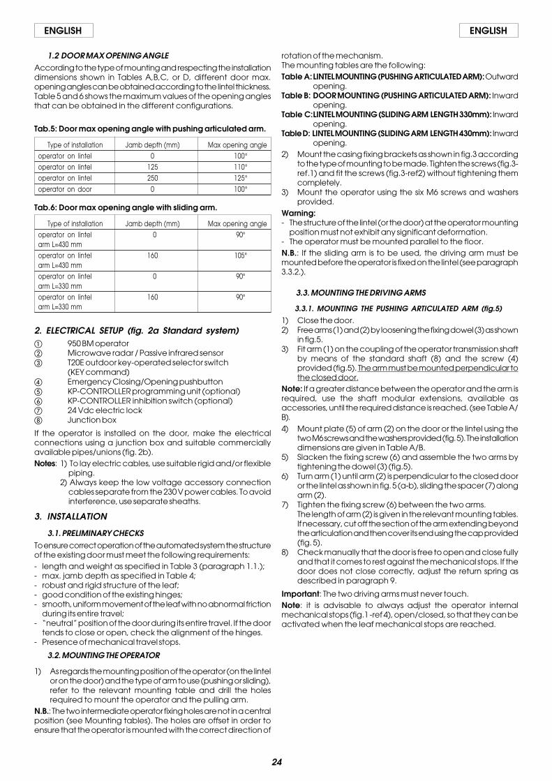
3.2. MOUNTING THE OPERATOR
1) As regards the mounting position of the operator (on the lintelor on the door) and the type of arm to use (pushing or sliding),refer to the relevant mounting table and drill the holesrequired to mount the operator and the pulling arm.
N.B.: The two intermediate operator fixing holes are not in a centralposition (see Mounting tables). The holes are offset in order toensure that the operator is mounted with the correct direction of
rotation of the mechanism.The mounting tables are the following:Table A:LINTEL MOUNTING (PUSHING ARTICULATED ARM): Outward
opening.Table B: DOOR MOUNTING (PUSHING ARTICULATED ARM): Inward
opening.Table C:LINTEL MOUNTING (SLIDING ARM LENGTH 330mm): Inward
opening.Table D: LINTEL MOUNTING (SLIDING ARM LENGTH 430mm): Inward
opening.2) Mount the casing fixing brackets as shown in fig.3 according
to the type of mounting to be made. Tighten the screws (fig.3-ref.1) and fit the screws (fig.3-ref2) without tightening themcompletely.
3) Mount the operator using the six M6 screws and washersprovided.
Warning:- The structure of the lintel (or the door) at the operator mounting
position must not exhibit any significant deformation.- The operator must be mounted parallel to the floor.N.B.: If the sliding arm is to be used, the driving arm must bemounted before the operator is fixed on the lintel (see paragraph3.3.2.).
3.3. MOUNTING THE DRIVING ARMS
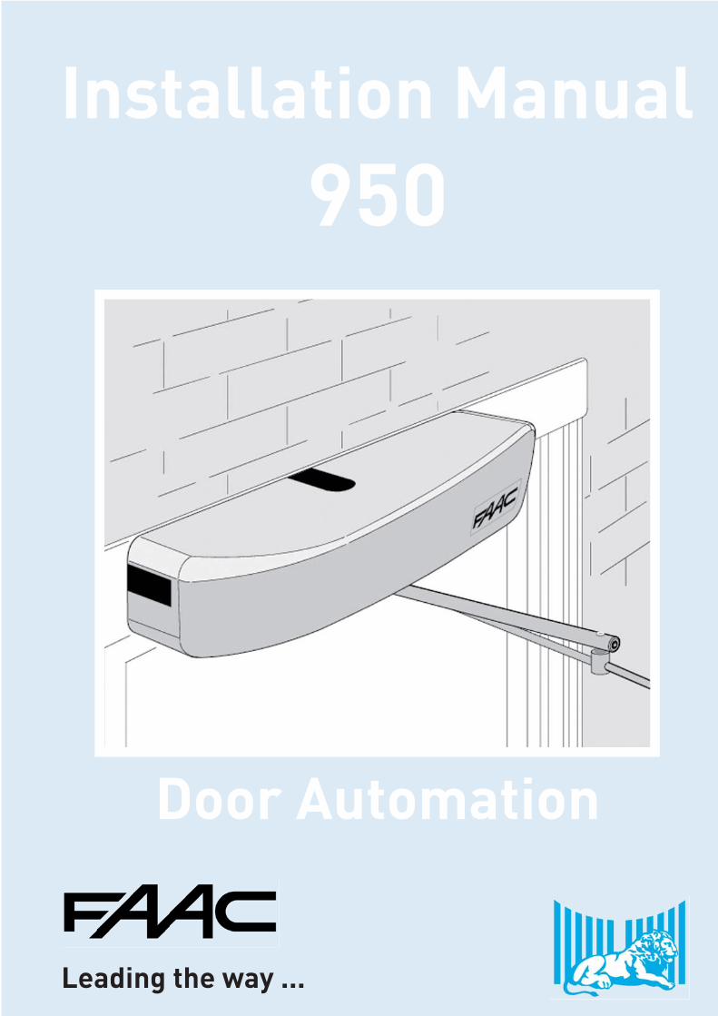
3.3.1. MOUNTING THE PUSHING ARTICULATED ARM (fig.5)
1) Close the door.2) Free arms (1) and (2) by loosening the fixing dowel (3) as shown
in fig.5.3) Fit arm (1) on the coupling of the operator transmission shaft
by means of the standard shaft (8) and the screw (4)provided (fig.5). The arm must be mounted perpendicular tothe closed door.
Note: If a greater distance between the operator and the arm isrequired, use the shaft modular extensions, available asaccessories, until the required distance is reached. (see Table A/B).4) Mount plate (5) of arm (2) on the door or the lintel using the
two M6 screws and the washers provided (fig. 5). The installationdimensions are given in Table A/B.
5) Slacken the fixing screw (6) and assemble the two arms bytightening the dowel (3) (fig.5).
6) Turn arm (1) until arm (2) is perpendicular to the closed dooror the lintel as shown in fig. 5 (a-b), sliding the spacer (7) alongarm (2).
7) Tighten the fixing screw (6) between the two arms.The length of arm (2) is given in the relevant mounting tables.If necessary, cut off the section of the arm extending beyondthe articulation and then cover its end using the cap provided(fig. 5).
8) Check manually that the door is free to open and close fullyand that it comes to rest against the mechanical stops. If thedoor does not close correctly, adjust the return spring asdescribed in paragraph 9.
Important: The two driving arms must never touch.Note: it is advisable to always adjust the operator internalmechanical stops (fig.1 -ref 4), open/closed, so that they can beactivated when the leaf mechanical stops are reached.
25
ENGLISH ENGLISH
3.3.2. MOUNTING THE SLIDING ARM (fig.6)1) Mount arm (1) on the operator transmission shaft by means
of the standard shaft (5) and the screw (2) provided (fig.6).The arm must be fitted pointing 45° outwards as shown in fig.6(a).
Note: If a larger distance is required between the operator andthe arm use the shaft modular extensions available as accessories,until the required distance is reached (see Table C/D).
Warning: Mount arm (1) on the transmission shaft before fitting theoperator on the lintel (fig.6).
2) Insert the teflon slide (3) inside the sliding guide (4) (fig.6).3) Pull arm (1) inwards manually as shown in fig. 6(b) and secure
the sliding guide (4) by means of two M6 screws on the closeddoor as shown in Table C/D.
4) Check manually that the door is free to open and close fullyand comes to rest against the mechanical travel stops. If thedoor does not close correctly, adjust the return spring asdescribed in paragraph 9.
4. START-UP1) Make the electrical connections to the 950 I/O electronic
control unit as described in paragraph 6, and connect themains power supply to the specific terminal (fig.1-ref.10)ensuring to crimp the earth wire to the lug (fig.1-ref.12)screwed to the support profile (fig.1-ref.2). Then tighten theterminal (fig.1-ref.13)To gain access to the control unit, pass the cables throughthe special conduit (fig.1-ref.1) or break the knockout areason the casing sides (fig.4-ref.6).
IMPORTANT: When mounting the “sliding” arm or for openingangles greater than 90°, turn microswitch no. 2 to ON beforeconnecting power to the system.
2) Close the door.3) Power up the operator.4) Check that the green LEDs LD1 and LD3 on the board 950MPS
light up.5) Check that the status signalling LEDs on the board 950I/O are
in the default status shown in Table 7 .
N.B.: The default status of the LEDs with the door closed at rest isshown in bold type.
Table 7: Operation of the status signalling LEDs for 950 I/O board
LED ON OFFLD1 Accessories power present Accessories power absent
LD2 Card Reader active Card Reader inactiveLD3 Internal sensor active Internal sensor inactiveLD4 External sensor active External sensor inactiveLD5 Emergency inactive Emergency active
LD6 STOP safety device inactive STOP safety device active
LD7 CL safety device inactive CL safety device active
LD8 Key active Key inactiveLD9 Fire-alarm active Fire-alarm active
6) Run a SET-UP cycle as indicated in paragraph 4.1.
4.1. SET UP PROCESSOnce the system is powered up, hold down SW1 button for at least5 sec., until the LD2 red LED on the 950MPS board lights up. The LEDwill start flashing to indicate that SET UP process is in progress.During this process the following parameters are set:- measuring the mass of the door;- determining the travel stop positions;The door opens at low speed, then closes half way beforeswitching back to opening.Subsequent closure is performed by the return spring.The process may be inhibited in any of the following conditions:- function selector switch in the 2 (MANUAL/NIGHT) position or KP-
CONTROLLER programming unit in MANUAL or NIGHT position.- incorrect connection of the accessories (electric lock, control/
safety devices);- incorrect positioning of the programming unit microswitches.Note: To repeat the initialisation procedure hold down the SW1button for more than 5 seconds.Check that door opens and closes correctly by sending anopening command to one of the following inputs: Internal Sensor,External Sensor or Key command. Set the trimmers (par.5.2) andprogram the microswitches (par.5.4) according requirements.
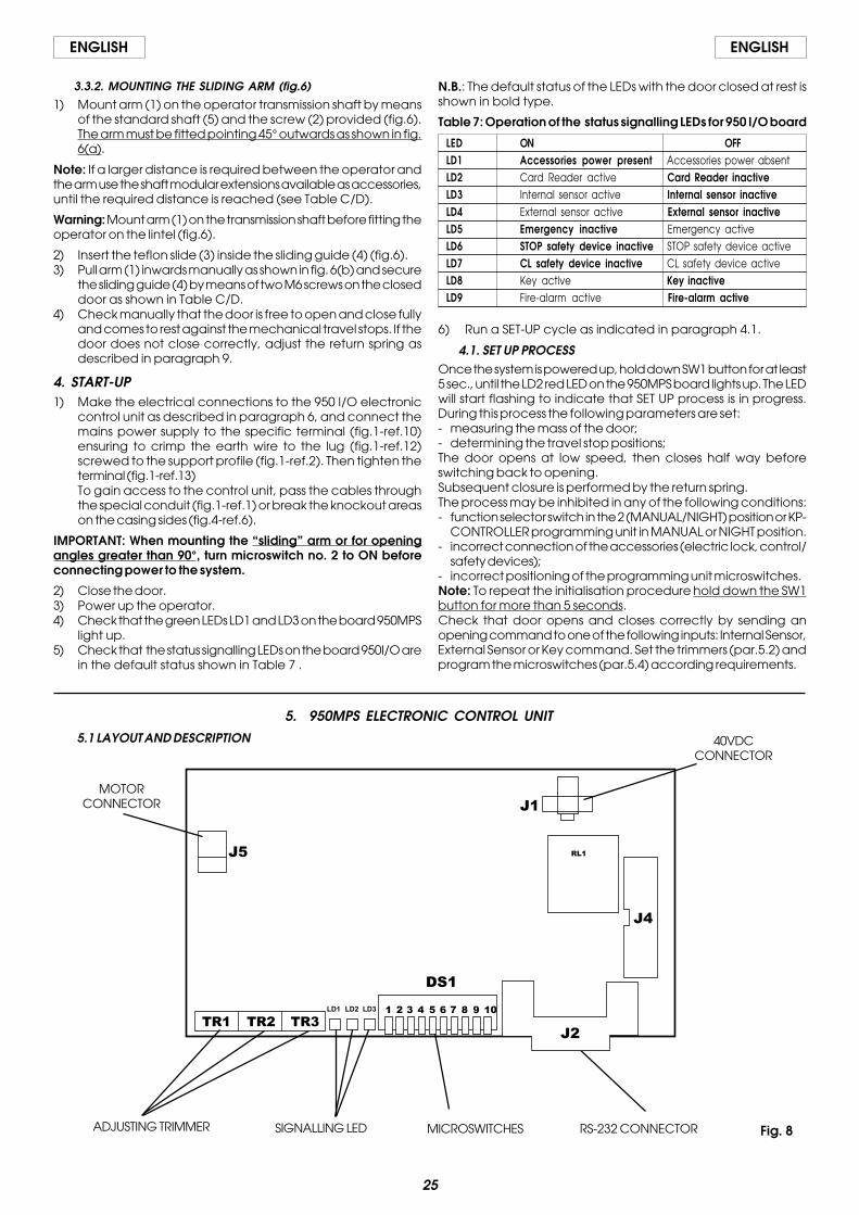
5. 950MPS ELECTRONIC CONTROL UNIT5.1 LAYOUT AND DESCRIPTION
MICROSWITCHES RS-232 CONNECTORADJUSTING TRIMMER SIGNALLING LED
MOTORCONNECTOR
40VDCCONNECTOR
Fig. 8
26
ENGLISHENGLISH
5.2. SETTING THE ADJUSTING TRIMMERSThe programming unit features trimmers (fig.8) which regulate thefollowing parameters:Trimmer TR1 to set the opening speed.Setting from 4 to 10 seconds.Trimmer TR2 to set the closing speed.Setting from 4 to 10 seconds.Trimmer TR3 to set the pause time (AUTOMATIC logic).Setting from 0 to 30 seconds.
5.3. SIGNALLING LEDsLD1 Led = Green LED - electric motor power supply.LD2 Led = Red LED - indicates SET-UP/Alarm.LD3 Led = Green LED - 5V power supply.
5.4.2. MICROSWITCH No. 2 - SET-UP PROCESSWhen mounting the “sliding” arm or for opening angles greaterthan 90°, this microswitch has to be enabled.
OFF = Function DISABLEDON = Function ENABLED
5.4.3. MICROSWITCH No. 3 - SELECTOR FUNCTION (“ 2 ” POSITION)
This function allows the operating function to be selected with theselector switch in the “2” position.
OFF = MANUAL FunctionON = NIGHT Function
5.4.4. MICROSWITCH No. 4 - PUSH AND GOWhen activated, this function enables the opening command tobe given by pushing the closed door manually. It is sufficient togive the door an initial push/pull in the opening direction.
OFF = Function DISABLEDON = Function ENABLED
WARNING: It is advisable not to enable this function if the door issubject to strong wind, according to its structure and dimensions,as this could activate the system's spontaneous opening ormotion reversing.
5.4.5 . MICROSWITCHES Nos. 5/6/8/9 - INACTIVE
5.4.6. MICROSWITCH No. 7 - STOP SAFETY DEVICEIt makes it possible to detect activation of the STOP safety deviceduring the entire door travel (COMPLETE) or to disable detectionbeyond 70° opening (REDUCED).
OFF = COMPLETE FunctionON = REDUCED Function
When the STOP safety control is ensured by an active sensor fittedon the leaf, if you enable the REDUCED function, the detectionof any obstacle (e.g. side wall) is prevented which would causeinterruption of the work cycle.
5.4.7 MICROSWITCH No. 10 - RS232 PORTIt makes it possible to enable the RS232 port connection to PC forsoftware update. In normal use conditions, the dip switch is in OFFposition.
OFF = Port DISABLEDON = Port ENABLED
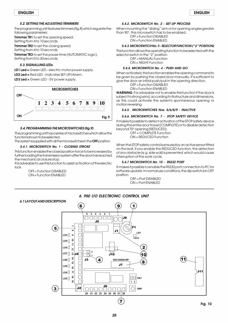
6. 950 I/O ELECTRONIC CONTROL UNIT
5.4. PROGRAMMING THE MICROSWITCHES (fig.9)The programming unit has a series of microswitches which allow thefunctions shown to be selected.The system is supplied with all the microswitches in the OFF position.
5.4.1. MICROSWITCH No. 1 - CLOSING STROKEThis function enables the closed position force to be increased byfurther loading the transmission system after the door has reachedthe mechanical closure stop.It is advisable to use this function to assist activation of the electriclock.
OFF = Function DISABLEDON = Function ENABLED
MICROSWITCHES
1 2 3 4 5 6 7 8 9 10
OFF
ON Fig. 9
Fig. 10
6.1 LAYOUT AND DESCRIPTION

27
ENGLISH ENGLISH
Warning: Always disconnect the electric power supply beforecarrying out any work on the control unit (connection,maintenance).
DS1 No.2: Lock activation delayOFF = DISABLEDON = ENABLED
If this dip-switch is enabled, the door movement is delayedby 500msec with respect to the electric lock command. Ifdisabled, delay is 200 msec. No.1: Inactive
SW1 SET-UP pushbuttonHold down the SET-UP button for 5 sec. to start the set-upcycle.
����� FUSE F1 4AT/230Vac - 5x20
����� J1 CONNECTOR Transformer Secondary winding - fig. 10
����� J2 CONNECTORRapid Connector of Manual/Night,Open,Automaticfunction selector switch
����� J3 CONNECTOR KP-Controller Connection
1- 2 Connector of KP-Controller programming unit (optional) asshown in fig. 24.Use a 2 x 0.5 mm² shielded cable (“bus” communication) forthe connection. Respect the connection polarity as shownin figure 24.Important: The maximum permissible length of the connectioncable is 50 m.To inhibit operation of the SD-KEEPER, make the jumperbetween terminals of the LOCK switch (fig.24).
����� J4 TERMINAL BOARD Inputs Connection (figs. 11,12,16)
7- 8 GNDAccessories power supply Negative and contacts Common
9 +24Vdc+24Vdc accessories power supply
10 Internal Command - N.O. ContactAny pulse generator (pushbutton, sensor, etc.) which, byclosing a contact, commands door opening.To install several pulse generators as Internal Command,connect the N.O. contacts in parallel.
11 External Command - N.O. ContactAny pulse generator (pushbutton, sensor, etc.) which, byclosing a contact, commands door opening.To install several pulse generators as External Command,connect the N.O. contacts in parallel.
12 Emergency Command - N.C. ContactAny pulse generator (normally a pushbutton) which, byopening a contact, commands an emergency closure of thesystem. Alternatively this input can be used to commandemergency opening by programming the system in a suitablemanner using the KP-CONTROLLER programming unit (optio-nal).To install several emergency command devices, connect theN.C. contacts in series.N.B.: If emergency command devices are not connected,jumper inputs 7 and 12.Attention: Using the KP-CONTROLLER programming unit, youcan change the type of contact from N.C. to N.O. contact.
13 CLOSURE Safety Command - N.C. ContactAny device (safety sensor, photocell, etc.) which, by openinga contact, has a safety effect on the closing movement of thedoor.The safety device causes an immediate reversing of theclosing movement of the door, but has no effect on theopening movement of the door.To install several CLOSURE safety devices, connect the N.C.contacts in series.N.B.: If CLOSURE safety devices are not installed, jumper inputs7 and 14.
14 STOP Safety Command - N.C. ContactAny device (safety sensor, photocell, etc.) which, by openinga contact, has a safety effect on the operating cycle. Inparticular, this safety device interrupts the opening/closingmovement of the door.When the safety device is disengaged, the door resumes itsopening/closing movement and continues to the end of thecycle.To install several STOP safety devices, connect the N.C.contacts in series.N.B.: If STOP safety devices are not installed, jumper inputs 7and 13.
7 8 9 10 11 12 13 14 15 16 17 18 19
GN
D
GN
D
+ 2
4 V
dc
Inte
rna
l Co
mm
an
d
Exte
rna
l Co
mm
an
d
Clo
sure
Sa
fety
Co
mm
an
d
STO
P S
afe
ty C
om
ma
nd
Eme
rge
nc
y C
om
ma
nd
Ke
y C
om
ma
nd
Fire
-ala
rm C
om
ma
nd
Ca
rd R
ea
de
r Co
mm
an
d
GN
D
GN
D
J4
Fig. 11
7 8 9 13 14 15
TX RX
PB SENSOR
+-
C
+
+
-
-
C
J4
Fig. 12
7 8 9 10 11 12 13 14 15 16 17 18 19
28
ENGLISHENGLISH
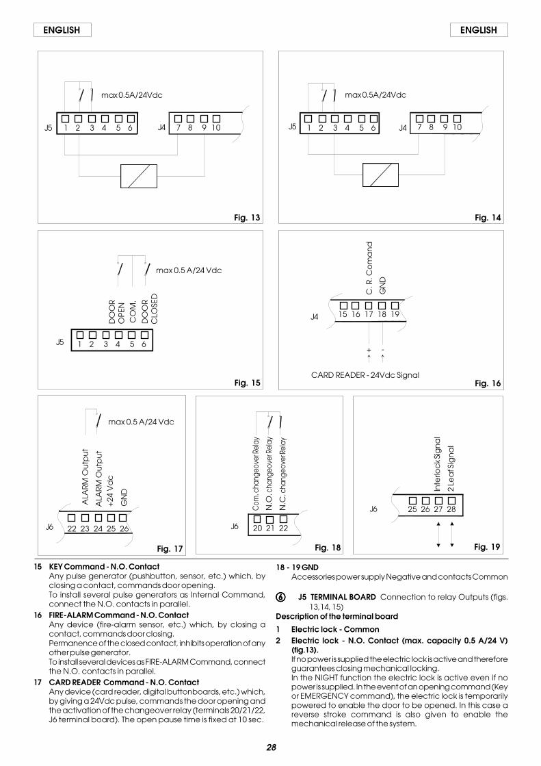
15 KEY Command - N.O. ContactAny pulse generator (pushbutton, sensor, etc.) which, byclosing a contact, commands door opening.To install several pulse generators as Internal Command,connect the N.O. contacts in parallel.
16 FIRE-ALARM Command - N.O. ContactAny device (fire-alarm sensor, etc.) which, by closing acontact, commands door closing.Permanence of the closed contact, inhibits operation of anyother pulse generator.To install several devices as FIRE-ALARM Command, connectthe N.O. contacts in parallel.
17 CARD READER Command - N.O. ContactAny device (card reader, digital buttonboards, etc.) which,by giving a 24Vdc pulse, commands the door opening andthe activation of the changeover relay (terminals 20/21/22,J6 terminal board). The open pause time is fixed at 10 sec.
18 - 19 GNDAccessories power supply Negative and contacts Common
����� J5 TERMINAL BOARD Connection to relay Outputs (figs.13,14, 15)
Description of the terminal board
1 Electric lock - Common2 Electric lock - N.O. Contact (max. capacity 0.5 A/24 V)
(fig.13).If no power is supplied the electric lock is active and thereforeguarantees closing mechanical locking.In the NIGHT function the electric lock is active even if nopower is supplied. In the event of an opening command (Keyor EMERGENCY command), the electric lock is temporarilypowered to enable the door to be opened. In this case areverse stroke command is also given to enable themechanical release of the system.
7 8 9 10 1 2 3 4 5 6J5 J4
max 0.5A/24Vdc
1 2 3 4 5 6 7 8 9 10J5 J4
max 0.5A/24Vdc
1 2 3 4 5 6
DO
OR
OP
EN
DO
OR
CLO
SED
CO
M.
max 0.5 A/24 Vdc
15 16 17 18 19
CARD READER - 24Vdc SignalC
. R. C
om
an
d
GN
D
+ -
22 23 24 25 26
max 0.5 A/24 Vdc
ALA
RM
Ou
tpu
t
ALA
RM
Ou
tpu
t+
24 V
dc
GN
D
Fig. 13 Fig. 14
Fig. 15 Fig. 16
Fig. 17 Fig. 18 Fig. 19
J4
J5
J6 J6
J6 25 26 27 28
Inte
rloc
k Si
gn
al
2 Le
af S
ign
al
20 21 22
Com
. cha
ngeo
ver R
elay
N.O
. cha
ngeo
ver R
elay
N.C
. cha
ngeo
ver R
elay
29
ENGLISH ENGLISH
3 Electric lock - N.C. contact (max. capacity 0.5 A/24 V) (fig.14).The output is suitable for commanding a magnetic closuresystem. If no power is supplied, the electric lock is not active.In the NIGHT function the electric lock is powered and henceactive. In the event of an opening command (internalcommand or EMERGENCY OPENING), the power supply tothe electric lock is temporarily cut off to allow the door to beopened.
4 Door status CLOSED - N.O. contact (max. capacity 0.5 A/24 V).When the door CLOSED position is reached, the contactcloses.
5 Door status - Common6 Door status OPEN - N.O. contact (max. capacity 0.5 A/24 V).
When the door OPEN position is reached, the contact closet.
����� J6 terminal board Relay outputs and special functions (figs.17, 18, 19)
Description of the terminal board
20 Changeover relay - Common21 Changeover relay - N.O. Contact
This output is activated (N.C.) by the Card Reader input for2 sec.Attention: this output is not suitable for controlling electriclocks.
22 Changeover relay - N.C. ContactThis output is activated (N.O.) by the Card Reader input for2 sec.Attention: this output is not suitable for controlling electriclocks.
23 Alarm Output - Common24 Alarm Output - N.O. Contact
This output is activated (N.C.) if an alarm is present. At thesame time LED2 on the 950 I/O board lights up to indicate thealarm condition.
25 +24Vdc+24Vdc accessories power supply
26 GNDAccessories power supply Negative and contacts Common
27 “Interlock”outputThis terminal is used to enable communication between two950BM automated systems programmed in “Interlock”configuration, see par. 11.1.
28 “2 Leaves” outputThis terminal is used to enable communication between two950BM automated systems programmed in “2 Leaves”configuration, see par. 11.2.
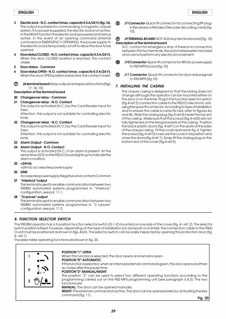
8. FUNCTION SELECTOR SWITCHThe 950 BM operator has a 3-position function selector switch (0-1-2) mounted on one side of the cover (fig. 4 - ref. 2). The selectorswitch position is fixed: however, depending on the type of installation (on doorpost or on lintel), the connection cable to the 950I/O unit must be positioned as shown in figs. 4a/b. The selector switch can be easily inspected by opening the protection door (fig.4 - ref.1).The selectable operating functions are shown in fig. 20.
1
0
2
POSITION "1": OPENWhen this function is selected, the door opens and remains open.POSITION "0": AUTOMATICIf this function is selected, when an internal/external command is given, the door opens and thenre-closes after the pause time.POSITION "2": MANUAL/NIGHTThe position “2” can be used to select two different operating functions according to theprogramming carried out on the 950 MPS programming unit (see paragraph 5.4.3). The twofunctions are:MANUAL: The door can be opened manually.NIGHT: The external command is inactive. The door can be opened solely by activating the Keycommand (fig. 11) .
7. INSTALLING THE CASINGThe closure casing is designed so that the styling does notchange although the operator can be mounted either onthe door or on the lintel. Plug in the function selector switch(fig.4-ref.2) connection cable to the 950 I/O electronic unit,using the quick-fit connector. According to type of installationand to ensure the cable is correctly laid, refer to figures 4aand 4b. Slide the closing plug (fig.4-ref 4) inside the top slotof the casing. Make sure that the screws (fig.4-ref3) are notfully tightened on the fixing brackets of the casing. Positionthe black plastic doors (fig. 4-ref1) on the seats at the sidesof the closure casing. Fit the cover as shownin fig. 4. Tightenthe screws (fig.4-ref 3) to secure the cover in its position andclose the doors (fig.4 ref.1). Snap-fit the closing plug on thebottom slot of the cover (fig.4-ref 5).
����� J7 Connector Quick-fit connector for connecting RP plug-in Receivers or Minidec/Decoder decoding cards (fig.10).
J9 TERMINAL BOARD NOT-AUS stop terminal board (fig. 10)Description of the terminal board
N.C. contact for emergency stop. If there is no connectionbetween the two terminals, the automated system is lockedand cannot perform any electrical movement.
����� J10 Connector Quick-fit connector for 40Vdc power supplyto 950 MPS board (fig.10)
����� J11 Connector Quick-fit connector for door status signalsto 950 MPS (fig.10)
Fig. 20

30
ENGLISHENGLISH
9. ADJUSTING THE SPRING
9.1. SPRING PRELOADING
If door movement is not uniform (e.g.: door not closingcompletely or closing with too much force) proceed as followsto adjust the spring preloading:1) Cut power to the automated system and release from the
door the arm secured directly on the transmission shaft;2) Rotate the arm until the stop-point screw (fig. 21 ref.4) is in
line with the inspection slot (fig. 21 ref. 3) ;3) Remove the screw, while keeping the arm in position;4) To increase preloading: rotate the arm in opening direction
until the next fixing position of the stop-point screw (fig.21ref.5) is in line with the inspection slot and fix the screwagain.To reduce preloading: rotate the arm in closing directionuntil the next fixing position of the stop-point screw (fig.21ref.5) is in line with the inspection slot and fix the screw again.
5) Reinstall the arm correctly (see par.3.3.);6) Run a new SETUP cycle.
9.2. CHECKING SPRING EFFICIENCY
We advise you to periodically check the efficiency of the spring- this is the procedure:1) Select the Manual function;2) Remove the protective device of the drive system (see fig. 1
ref. 6);1) With the door closed, trace a vertical line on the spring (fig.
22 ref.1 );2) Open the door completely;3) Check the line you had traced.
If distortion is not uniform along the whole spring height (fig.22 ref.2 ), but is irregular (fig.22 ref.3 ), lubricate the springwith specific sliding grease.
Fig. 22� � �
�
�
� Closing limit-switch� Opening limit-switch� Slot for inspection of stop-point screw� Stop-point screw� Fixing positions of stop-point screw
��
��
Fig.21
31
ENGLISH ENGLISH
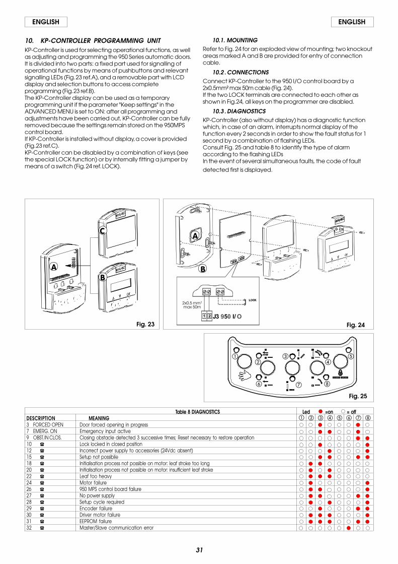
10. KP-CONTROLLER PROGRAMMING UNITKP-Controller is used for selecting operational functions, as wellas adjusting and programming the 950 Series automatic doors.It is divided into two parts: a fixed part used for signalling ofoperational functions by means of pushbuttons and relevantsignalling LEDs (Fig. 23 ref.A), and a removable part with LCDdisplay and selection buttons to access completeprogramming (Fig. 23 ref.B).The KP-Controller display can be used as a temporaryprogramming unit if the parameter "Keep settings" in theADVANCED MENU is set to ON: after all programming andadjustments have been carried out, KP-Controller can be fullyremoved because the settings remain stored on the 950MPScontrol board.If KP-Controller is installed without display, a cover is provided(Fig. 23 ref.C).KP-Controller can be disabled by a combination of keys (seethe special LOCK function) or by internally fitting a jumper bymeans of a switch (Fig. 24 ref. LOCK).
10.1. MOUNTINGRefer to Fig. 24 for an exploded view of mounting; two knockoutareas marked A and B are provided for entry of connectioncable.
10.2 . CONNECTIONSConnect KP-Controller to the 950 I/O control board by a2x0.5mm² max 50m cable (Fig. 24).If the two LOCK terminals are connected to each other asshown in Fig.24, all keys on the programmer are disabled.
10.3 . DIAGNOSTICSKP-Controller (also without display) has a diagnostic functionwhich, in case of an alarm, interrupts normal display of thefunction every 2 seconds in order to show the fault status for 1second by a combination of flashing LEDs.Consult Fig. 25 and table 8 to identify the type of alarmaccording to the flashing LEDsIn the event of several simultaneous faults, the code of fault
detected first is displayed.
2x0.5 mm2
max 50m
Fig. 24
�
�
Fig. 23
�
�
�
Table 8 DIAGNOSTICS Led =on = offDESCRIPTION MEANING3 FORCED OPEN Door forced opening in progress7 EMERG. ON Emergency input active9 OBST. IN CLOS. Closing obstacle detected 3 successive times; Reset necessary to restore operation10 � Lock locked in closed position12 � Incorrect power supply to accessories (24Vdc absent)15 � Setup not possibile18 � Initialisation process not possible on motor: leaf stroke too long20 � Initialisation process not possible on motor: insufficient leaf stroke22 � Leaf too heavy24 � Motor failure26 � 950 MPS control board failure27 � No power supply28 � Setup cycle required29 � Encoder failure30 � Driver motor failure31 � EEPROM failure32 � Master/Slave communication error
� � � � � ���
��
��
�
� � �
Fig. 25

32
ENGLISHENGLISH
10.4 . OPERATIONAL FUNCTIONSSelection is performed by pressing the keys on the fixed part ofthe programmer - the function is indicated by thecorresponding LED lighting up.Note: when the “Night” or “Manual” modes have been set, therelevant selection keys must be pressed to exit the modes.
MANUALThe door is free and can be activated manually.
BI-DIRECTIONALPedestrian transit is possible in both directions; the inside andoutside radars are enabled.
ONE-WAYPedestrian transit is possible in one direction only; the externalradar is disabled.
PARTIAL OPENINGThe door opens only partially (standard: 80%)Partial opening can be adjusted in range from 60% to 90% oftotal.
TOTAL OPENINGThe door opens completely.
AUTOMATICThe door opens (partially or totally) and then re-closes after theset pause time (standard: 2 sec.).Pause time adjustment: form 0 to 30 sec.
DOOR OPENThe door opens and stays open.
NIGHTThe door closes and the lock (if present) is activated. Theinternal and external radars are disabled.The Key command causes opening and closing after the nightpause time elapses (standard: 7 sec).Adjusting range of night pause time: from 0 to 30 sec.To obtain partial opening in this mode, before selecting the“Night” function, activate the “Partial Opening” function.
10.5 . SPECIAL FUNCTIONS
SETUPSetup is the door initialisation function during which parametersare self-learned.To activate, simultaneously press keys and E for � sec.
RESETReset is the function for restoring normal operating conditionsafter some types of alarm have been signalled.To activate, simultaneously press keys � and �.
LOCKWhen active, the Lock function disables KP-Controller.To activate and de-activate, simultaneously press keys � and� for 5 sec.
10.6 . INSERTING AND CHANGING BATTERYTo keep the clock inside KP-Controller active even in the eventof a power cut, a 3V model CR1216 lithium battery has to beinstalled.To insert or change the battery, find the compartment on theprinted circuit (Fig. 27) and observe the indicated polarity.
Fig. 27
Fig. 26
� � �
�
�
�
�
�
MANUAL
BI-DIRECTIONAL
ONE-WAY
PARTIAL OPENING
TOTAL OPENING
AUTOMATIC
DOOR OPEN
NIGHT

33
ENGLISH ENGLISH
10.7. PROGRAMMINGTo access programming while the standard view is shown onthe display, press any of keys �, � or OK.Programming is subdivided into main menus (see Chart 1) splitinto subjects.After selecting the menu with keys � or �, to access it press OK.Each menu is, in turn, subdivided into sub-menus at differentparameter setting levels.Use keys � or � to select (sub-menu or parameter) and confirmwith the OK key.An asterisk on the display indicates the currently active setting.To exit programming, select the “exit” function at each level.Otherwise, after about 2 minutes, the display automaticallyreturns to standard view.The following flow-charts and notes show the variousprogramming menus and options.
Diagram 2: Language selection
Diagram 1: Programming
DAY HOUR VER DATE
SETUP
TIMER
LANGUAGE
TIMERPROGRAMMING
CLOCK
ADVANCED MENU
DIAGNOSTICS
LOCK
ITALIANO
ENGLISH
DEUTSCH
FRANCAIS
ESPANOL
LANGUAGE

34
ENGLISHENGLISH
Diagram 3: Setup
Diagram 4: Lock
SETUP 80%
7 SEC.
*
*
2 SEC. *
CLOSING:STANDARD
NO STANDARD
*OBSTACLEDETECTION
NIGHT PAUSETIME
PARTIALOPENING
PAUSE TIME
EXIT
LOCK
OFF
ON **
ALWAYS
ONE WAY+NIGHT
NIGHTKIT
LOCK
EXIT

35
ENGLISH ENGLISH
Diagram 5: Diagnostics
Diagram 6: Operation parameters
RESET
950 v.DIAGNOSTICS NR. CYCLEXXXX
ALARM N.(alarm description)
PASSWORD0000
PASSWORD0000
PASSWORD0000
PASSWORD0000
KEEPSETTINGS
OFF
ON
8
8
EXIT
*
*
*
ADVANCED MENU
OPERATIONPARAMETERS CLOSING SPEED
OPENING SPEED
correct code
incorrect code
IN/OUT SETUP
VARIOUS
EXIT
CHANGEPASSWORD
36
ENGLISHENGLISH
Diagram 7: In/Out Setup
PASSWORD0000
PASSWORD0000
PASSWORD0000
PASSWORD0000
IN/OUT SETUP EMERG OPEN
CLOSE
OUT OP/CL NO
OUT ALARM NO
NC
USCITA
*
*
NC
NO
NC
*
*
ADVANCED MENU
OPERATIONPARAMETERS
VARIOUS
EXIT
CHANGEPASSWORD
correct code
incorrect code
37
ENGLISH ENGLISH
codice errato
codice corretto
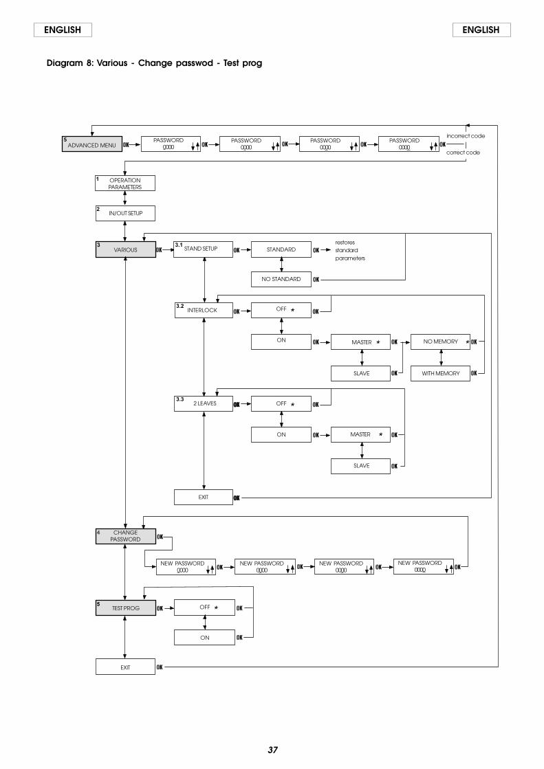
Diagram 8: Various - Change passwod - Test prog
PASSWORD0000
PASSWORD0000
PASSWORD0000
PASSWORD0000
IN/OUT SETUP
STAND SETUP STANDARD
NO STANDARD
INTERLOCK
MASTER
SLAVE
NO MEMORY
WITH MEMORY
EXIT
NEW PASSWORD0000
NEW PASSWORD0000
NEW PASSWORD0000
NEW PASSWORD0000
**
MASTER
SLAVE
ON
OFF *
ON
OFF *
2 LEAVES
*
TEST PROG
ON
OFF *
ADVANCED MENU
OPERATIONPARAMETERS
VARIOUS
EXIT
CHANGEPASSWORD
correct code
incorrect code
restoresstandardparameters

38
ENGLISHENGLISH
Diagramma 9: Clock
Diagram 10: Timer
Diagram 11: Timer programming
SUN 00:00 00/00/00CLOCK
SUN 00:00 00/00/00
SUN 00:00 00/00/00
SUN 00:00 00/00/00
SUN 00:00 00/00/00
SUN 00:00 00/00/00
SUN 00:00 00/00/00
SUN 00:00 00/00/00
SUN 00:00 00/00/00
SUN 00:00 00/00/00
SUN 00:00 00/00/00
TIMER
ON
OFF *
TIME BAND: 1FUN: 0 00:00
TIME BAND: 2FUN: 0 00:00
TIME BAND: 5FUN: 0 00:00
TIME BAND: 4FUN: 0 00:00
TIME BAND: 3FUN: 0 00:00
TIME BAND: 1FUN: 0 00:00
TIME BAND: 2FUN: 0 00:00
TIME BAND: 5FUN: 0 00:00
TIME BAND: 4FUN: 0 00:00
TIME BAND: 3FUN: 0 00:00
TIME BAND: 1FUN: 0 00:00
TIME BAND: 2FUN: 0 00:00
TIME BAND: 5FUN: 0 00:00
TIME BAND: 4FUN: 0 00:00
TIME BAND: 3FUN: 0 00:00
TIME BAND: 1FUN: 0 00:00
TIME BAND: 2FUN: 0 00:00
TIME BAND: 5FUN: 0 00:00
TIME BAND: 4FUN: 0 00:00
TIME BAND: 3FUN: 0 00:00
TIME BAND: 1FUN: 0 00:00
TIME BAND: 2FUN: 0 00:00
TIME BAND: 5FUN: 0 00:00
TIME BAND: 4FUN: 0 00:00
TIME BAND: 3FUN: 0 00:00
TIMERPROGRAMMING
ALL DAYS
SUN
MON
WED
TUE
SAT
FRI
THU
EXIT

39
ENGLISH ENGLISH
1 LANGUAGE (Diagram 2)Select the language for showing the messages on the display
2 SETUP (Diagram 3)2.1 PARTIAL OPENINGPartial opening percentage
Select the opening percentage (referred to total opening)performed in the “Partial Opening” operational function.Standard value: 80%Adjusting range: from 60% to 100%
2.2 PAUSE TIMEPause time value
Set pause time in the automatic operational functionStandard value: 2 sec.Adjusting range: from 0 to 30 sec.
2.3 NIGHT PAUSE TIMENight pause time value
Set pause time in the “night” operational functionStandard value: 7 sec.Adjusting range: from 0 to 30 sec.
2.4 OBSTACLE DETECTIONDetermines the behaviour of the automated system in theevent of repeated obstacle detection during the samemanoeuvre.
StandardThe automated system tries to complete the manoeuvre.
Non StandardIf an obstacle is detected for 3 consecutive times, theautomated system stops. After removing the obstacle, the doorhas to be closed manually to restore normal operation
3 LOCK (Diagram 4)3.1 KIT LOCKOn
Lock installed.Night
The lock locks the door only in the “Night” operational function.One-way+Night
The lock locks the door in the “Night” and “one-way”operational functions.
AlwaysThe lock locks the door whenever this closes, irrespective of theset operational function.
OffLock not installed.
4 DIAGNOSTICS (Diagram 5)4.1 950
The door's hardware model and the software of the 950 MPSand 950 I/O control boards to which KP-Controller isconnected are shown.
4.2 CYCLES No.The count (non resettable) of the cycles effected by theautomated system is shown
4.3 ALARM No.The number and description of the current alarm are shown.Refer to table 1 for error codes and descriptions.
RESETExecutes reset procedure and, if the cause of signalledmalfunction was removed, it restores normal operation.
5 ADVANCED MENUPASSWORDTo access the advanced menu, insert the 4-digit password(default 0000).
1 OPERATION PARAMETERS (Diagram 6)1.1 CLOSING SPEED
Sets door speed for closing.Standard value: level 8Adjusting range: from 0 to 10
1.2 OPENING SPEEDSets door speed for opening.Standard value: level 8Adjusting range: from 0 to 10
1.3 KEEP SETTINGSOn
The automated system maintains the operating parameters setwith KP-Controller even if this is disconnected.
OffIf the KP-Controller is disconnected, the settings of opening andclosing speeds and pause time must be made using thetrimmers (see Par. 5.2)
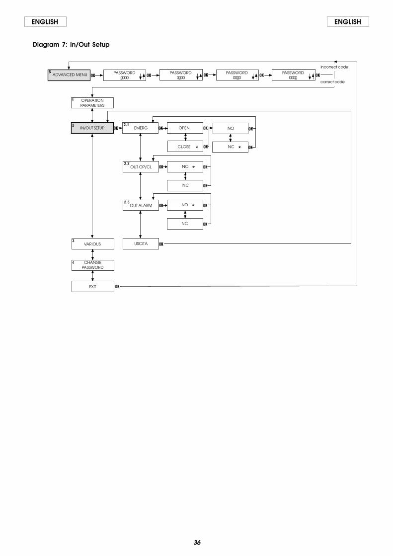
2 IN/OUT SETUP (Diagram 7)2.1 EMERG
Sets the effect of the emergency command (Emerg input on950 I/O control board).Standard setting: Opens/NC
OpenActivating this command opens the door.
CloseActivating this command closes the door.
NONormally open input.
NCNormally closed input.
2.2 OUT OP/CLSets operation of Open and Closed status outputs of 950 I/Ocontrol boardStandard setting: NO
NCNormally closed input.
NONormally open input.
2.3 OUT ALARMSets operation of Alarm status outputs of 950 I/O control boardStandard setting: NO
NONormally open input.
NCNormally closed input.
3 VARIOUS (Diagram 8)
3.1 STANDARD SETUPUsed for checking if any non-standard programming operationwas effected.
StandardIf no function was modified with respect to the standardprogramming, an asterisk is shown.If the asterisk is not present, press the “OK” key and all standardprogramming functions are reset.
Non StandardIf at least one function was modified with respect to thestandard programming, an asterisk is shown.
3.2 INTERLOCKThe interlock function makes it possible to control two doors(master and slave) so that opening of one depends on closingof the other and vice versa.
OffInterlock function not active.
OnActivates the interlock function.
40
ENGLISHENGLISH
MasterThe master door (usually the internal one).
SlaveThe slave door.
No MemoryWith interlock operation, you must wait for one door to closebefore commanding the other to open: any opening pulsessent during the operating cycle of the first door, have not effect.
With MemoryWith interlock operation, there is not need to wait for one doorto close before commanding the other to open: any openingpulses sent during the operating cycle of the first door arememorised, and the second door opens automatically as soonas the first door closes.
3.3 2 LEAVESThe “2 LEAVES” function is used to control 2-leaf doors. The twoautomated systems (master and slave) synchronously controldoor movement. The Master function must be associated withthe door which begins the opening movement first.
Off“2 LEAVES” function not active.
OnActivates the “2 LEAVES” function.
MasterThe master door (if the leaves have an overlap, it is always thefirst to start the opening movement).
SlaveThe slave door.
4 CHANGE PASSWORDSets the new password for accessing (4 digits) the advancedmenu. Default 0000.
5 TEST PROG.Runs an operational test of the automated system. If amalfunction is detected, the system stops and the KP-Controllersignals the detected malfunction status.
OffTest function not active.
OnActivates the test function.
6 CLOCK (Diagram 9)Sets the current day, time and date.
7 TIMER (Diagram10)Off
Timer not activated.On
Timer activated: the operating time bands set in “8 TimerProgramming” are enabled.When the timer is activated, a “T” appears at the side of thetime shown on the display and the KP-Controller will not allowany operational selection.The battery inside the KP-Controller maintains the clock inoperation even if power is not supplied; if correct time is lost (e.g.black-out and discharged battery), a flashing asterisk appearsin place of the “T”, the timer is disabled and the systemautomatically commutates into the NIGHT function.
8 TIMER PROGRAMMING (Diagram 11)With the timer, you can create up to 5 different time bands foreach day of the week (by setting the band starting time) andassign an operational function to each time band.When the KP-Controller's internal clock reaches the startingtime of a band, the associated operating function isautomatically set, and the door remains in this condition untilthe subsequent band intervenes.
Permanent connection of the KP-Controller+Display isnecessary for correct management of time bands.
Selecting the daySelects the day of the week to create time bands.If you select “All days”, any time bands defined subsequentlyare included in all days of the week.
FunctionSets the operating function to be associated with the timeband by referring to the following table:
FUN MEANING0 NO FUNCTION1 AUTOMATIC BI-DIRECTIONAL TOTAL2 AUTOMATIC ONE WAY TOTAL3 AUTOMATIC BI-DIRECTIONAL PARTIAL4 AUTOMATIC ONE WAY PARTIAL5 DOOR TOTALLY OPEN6 DOOR PARTIALLY OPEN7 MANUAL8 NIGHT
Time band starting timeSets the activation time for the time band.There is no need for the time bands to be in chronologicalorder.
-Programming example -We wish to program a door operating at the following times:•from MONDAY to FRIDAY:
- from 8 a.m. in AUTOMATIC BI-DIRECTIONAL TOTAL- from 6 p.m. in AUTOMATIC ONE WAY TOTAL- from 7 p.m. in NIGHT
•SATURDAY and SUNDAY: NIGHT for the whole day
Proceed as follows:
select ALL DAYS and set the following:TIME BAND 1 : FUN 1 08:00TIME BAND 2 : FUN 2 06:00 p.m.TIME BAND 3 : FUN 8 07:00 p.m.TIME BAND 4 : FUN 0TIME BAND 5 : FUN 0
Select SATURDAY and set the following:TIME BAND 1 : FUN 0TIME BAND 2 : FUN 0TIME BAND 3 : FUN 0TIME BAND 4 : FUN 0TIME BAND 5 : FUN 0
Select SUNDAY and set the following:TIME BAND 1 : FUN 0TIME BAND 2 : FUN 0TIME BAND 3 : FUN 0TIME BAND 4 : FUN 0TIME BAND 5 : FUN 0
Note: for correct use of the TIMER function, the battery of theKP-Controller must be efficient. In case of a power cut, thebattery keeps the clock in operation. If the battery isdischarged, the clock resets and, when power is restored, theKP-Controller automatically switches to NIGHT.For automated systems which are not powered for long periods(e.g. 12 hours out of 24 for 365 days a year), we advise you toreplace the battery not later than every 3 years.

41
ENGLISH ENGLISH
11. SPECIAL APPLICATIONS
11.1. INTERLOCKThe interlock function makes it possible to control two doors(master and slave) so that opening of one depends on closingof the other and vice versa.
11.1.1. INTERLOCK WITH INTERNAL SENSORSThis application is recommended when the distance betweenthe two doors is sufficient to avoid interference in the detectionranges of the two internal sensors.•Make the connections between the 950I/O control units ofthe two automated systems and the sensors as shown in figure28.•Program the following functions (see advanced progr.):-“interlock” active on both doors,-select the “MASTER” option for the internal door, and the“SLAVE” option for the external one,-select, for both doors, option “interlock without memory” or“interlock with memory”.
Important:•The sensors must be connected only to the Key input of thecontrol units;•The interlock will operate only if both doors are set to the NIGHTor ONE-WAY operating function.
OperationThese are the interlock operational stages:
1) The person on the outside activates sensor S1 of door A;2) Door A opens;3) The person enters the internal space between the two
doors;4) Door A closes after the night pause time elapses;5) The person activates sensor S3 of door B (If the “Interlock with
memory” option was selected, there is no need to wait forthe first door to close totally in order to activate the sensor ofthe second door);
6) Door B opens;
Fig. 28
Door A Door B
7) The person exits;8) Door B closes after the night pause time elapses.The operation is identical if the person comes from the opposite
direction.
11.1.2. INTERLOCK WITHOUT INTERNAL SENSORSThis application is recommended if the doors are so near toone another that the two internal sensors cannot be used; twopushbuttons have to be installed for activating the doors fromthe outside; no presence sensors are used.•Make the connections between the 950I/O control units ofthe two automated systems, of the pushbuttons andadditional electronic components as shown in figure 29.•Program the following functions (see advanced progr.):-“interlock” active on both doors,-select the “MASTER” option for the internal door, and the“SLAVE” option for the external one,-select the “interlock with memory” option for both doors.
Important:•The pushbuttons must be connected only to the Key input ofthe control units;•The interlock will operate only if both doors are set to the NIGHTor ONE-WAY operating function.
OperationThese are the interlock operational stages:
1) The person on the outside activates pushbutton B1 of doorA;
2) Door A opens;3) The person enters the internal space between the two
doors;4) Door A closes after the night pause time elapses;5) Door B opens automatically;7) The person exits;8) Door B closes after the night pause time elapses.The operation is identical if the person comes from the oppositedirection.
Fig. 29
Door A Door B

42
ENGLISHENGLISH
11.2. 2 LEAVESThe “2 LEAVES” function makes it possible to manage two opposingdoors with a synchronised movement and preset delay angles(these cannot be modified).The leaf controlled by the master automated system (see fig. 30)is the first to start the opening movement and, when it has reachedthe opening angle preset for leaf delay, the slave leaf begins itsmovement too.Likewise, when closing, the master begins to move only when theslave has reached the closing angle preset for leaf delay.If one of the automated systems detects an obstacle, themovement of both leaves is immediately reversed.The partial opening function enables control of total opening ofthe master only.The operating functions must be set on the master automatedsystem only (or on the KP-Controller if connected).
•Make the connections between the 950I/O control unit ofthe two automated systems as shown in fig. 31.
•Connect all sensors and pulse generators to the masteronly.
•Program the following functions (see advancedprogramming):- “2 LEAVES” active on both doors;- Select the “MASTER” option for the door due to begin the
opening movement first, and select “SLAVE” for the otherdoor.
- Set the same motion parameters on the two automatedsystems;
- If you wish to disconnect the KP-Controller from the slavedoor, you have to set function “KEEP SETTINGS” to ON;
Master Slave
Slave Master
Fig. 30
Fig. 31

43
ENGLISH ENGLISH
950 BM AUTOMATION SYSTEM End-user guide
MANUAL OPERATIONIf the door has to be activated manually due to failure of theelectrical power supply or a malfunction of the automatic unit,proceed as follows:
Function selector- Turn the selector to the “2” MANUAL/NIGHT position (fig.1).- Open or close the door manually.
KP-Controller unit- Press the button ( ) to set the operating function to the manual
(fig.2-Tab.1) the relavant LED lit steadily.
RETURN TO NORMAL OPERATIONFunction selector- Turn the function selector to the “0” AUTOMATIC position (fig.1).
KP-Cpontroller unit- Press again the Manual selection button ( ) to exit the relevant
operating function and select the new operating mode (Tab.1)using the relevant buttons (Fig.2). The function is shown bysteadily lit LED’s.
Fig. 2
POSITION "1": OPENWhen this function is selected, the dooropens and remains open.The door closurecan be controlled only activating theEmergency command.POSITION "0": AUTOMATICIf this function is selected, when an internal/external or Key command is given, the dooropens and then re-closes after the pausetime.POSITION "2": MANUAL/NIGHTThe position “2” can be used to select twodifferent operating functions according tothe programming carried out on the 950 MPSprogramming unit . The two functions are:MANUAL: The door can be openedmanually.NIGHT: The external command is inactive.The door can be opened solely by activatingthe Key command .
Read the end user guide carefully before using the product andkeep it in a safe place for future reference.
GENERAL SAFETY REGULATIONSWhen correctly installed and used, the 950 BM automatic unitassures a high level of safety. A few simple rules should be followedto prevent problems from arising accidentally:- Do not stand or allow children or adults to stand within range
of the door, especially during operation, and do not leaveobjects near it.
- Do not allow children to play with the door.- Do not deliberately obstruct movement of the door.- Keep the “automatic door” signs efficient and clearly visible.- In the event of a malfunction, select MANUAL OPERATION and
wait for a qualified technician to perform the necessary repairwork.
- Do not modify the components of the automatic unit.- Do not attempt to repair the automatic unit or to perform any
operation on it. Call qualified FAAC technicians only.- At least once every 6 months have qualified personnel check
that the automatic unit, safety devices and earth connectionare in working order.
DESCRIPTIONThe 950 BM automatic unit for swing doors is a one-piece unit consistingof an electromechanical device that allows door opening to becontrolled by means of a driving arm. The door is re-closed by a springsystem.The operator can be installed either on the lintel or on the door structureitself.The stainless steel protective casing houses the electronic control unitused to program and control the operation of the system.The automatic unit 950 BM has a selector which can be used tochoose the operating logic shown in fig. 1. A “KP-Controller”programming unit (fig. 2) can be installed as an alternative to thefunction selector, in which case the operating functions in Tab.1are available:
OPERATING FUNCTIONS
Selection is performed by pressing the keys on the fixed part ofthe programmer - the function is indicated by thecorresponding LED lighting up.Note: when the “Night” or “Manual” modes have been set, therelevant selection keys must be pressed to exit the modes.
�
�
�
�
PARTIAL OPENING
MANUAL
BIDIRECTIONAL
MONODIRECTIONAL
TOTAL OPENING
AUTOMATIC
DOOR OPEN
NIGHT
Tab.1
� � �
�
1
0
2
Fig. 1

Le descrizioni e le illustrazioni del presente manuale non sono impegnative. La FAAC si riserva il diritto,lasciando inalterate le caratteristiche essenziali dell’apparecchiatura, di apportare in qualunquemomento e senza impegnarsi ad aggiornare la presente pubblicazione, le modifiche che essa ritieneconvenienti per miglioramenti tecnici o per qualsiasi altra esigenza di carattere costruttivo o commer-ciale.
The descriptions and illustrations contained in the present manual are not binding. FAAC reserves theright, whilst leaving the main features of the equipments unaltered, to undertake any modifications itholds necessary for either technical or commercial reasons, at any time and without revising the presentpublication.
Les descriptions et les illustrations du présent manuel sont fournies à titre indicatif. FAAC se réserve le droitd’apporter à tout moment les modifications qu’elle jugera utiles sur ce produit tout en conservant lescaractéristiques essentielles, sans devoir pour autant mettre à jour cette publication.
Die Beschreibungen und Abbildungen in vorliegendem Handbuch sind unverbindlich. FAAC behält sichdas Recht vor, ohne die wesentlichen Eigenschaften dieses Gerätes zu verändern und ohneVerbindlichkeiten in Bezug auf die Neufassung der vorliegenden Anleitungen, technisch bzw. konstruktiv/kommerziell bedingte Verbesserungen vorzunehmen.
Las descripciones y las ilustraciones de este manual no comportan compromiso alguno. FAAC se reservael derecho, dejando inmutadas las características esenciales de los aparatos, de aportar, en cualquiermomento y sin comprometerse a poner al día la presente publicación, todas las modificaciones queconsidere oportunas para el perfeccionamiento técnico o para cualquier otro tipo de exigencia decarácter constructivo o comercial.
Timbro del Rivenditore:/Distributor’s Stamp:/Timbre de l’Agent:/ Fachhändlerstempel:/Sello del Revendedor:
FAAC S.p.A.Via Benini, 140069 Zola Predosa (BO) - ITALIATel.: 051/61724 - Fax: 051/758518www.faacgroup.com
FAAC per la natura• La presente istruzione è realizzata al 100% in carta riciclata.• Non disperdete nell'ambiente gli imballaggi dei componenti dell'automazione bensì selezionate i vari
materiali (es. cartone, polistirolo) secondo prescrizioni locali per lo smaltimento rifiuti e le norme vigenti.
FAAC for the environment• The present manual is produced in 100% recycled paper• Respect the environment. Dispose of each type of product packaging material (card, polystyrene) in
accordance with the provisions for waste disposal as specified in the country of installation.
FAAC der Umwelt zuliebe• Vorliegende Anleitungen sind auf 100% Altpapier gedruckt.• Verpackungsstoffe der Antriebskomponenten (z.B. Pappe, Styropor) nach den einschlägigen Normen
der Abfallwirtschaft sortenrein sammeln.FAAC écologique• La présente notice a été réalisée 100% avec du papier recyclé.• Ne pas jeter dans la nature les emballages des composants de l’automatisme, mais sélectionner les
différents matériaux (ex.: carton, polystyrène) selon la législation locale pour l’élimination des déchetset les normes en vigueur.
FAAC por la naturaleza.• El presente manual de instrucciones se ha realizado, al 100%, en papel reciclado.• Los materiales utilizados para el embalaje de las distintas partes del sistema automático (cartón,
poliestireno) no deben tirarse al medio ambiente, sino seleccionarse conforme a las prescripcioneslocales y las normas vigentes para el desecho de residuos sólidos.
7326
78 - R
ev.
A
��
����
���
���
���
�
��
�
���
�
���
���
���
���
���
��
����
�
��
����
��
�
��
���
��
��
��
���
����
���
��
��
���
������
���
�
����
��
���
�����
���
��
��
��
�
��
���
����
����
����
��
�
��
����
���
��

FAAC (UK) Limited, 6 Hamilton CloseHoundmills Estate, Basingstoke, RG21 6YTTelephone: 01256 318100Fax: 01256 318101Email: [email protected]: www.faac.co.uk
V5 01/07
Your authorised FAAC dealer
The descriptions and illustrations contained in this manual are not binding. FAAC reserve the right, whilst leaving the main features of the main equipment unaltered, to undertake any modifi cations it holds necessary for either technical or commercial reasons, at any time and without revising the present publication.