H230 - Stagnoli · I H230 di Stagnoli è la centrale di comando studiata per automazioni Hercules a...
84
Stagnoli T.G. srl Via Mantova, trav. I, 105A/B +39.0309139511 +39.0309139580 [email protected] www.stagnoli.com H230 Centrale di comando per motori Hercules a 230V I Control board for Hercules 230V motors GB Centrale de commande pour moteurs Hercules 230V F Steuerzentrale für Hercules-Motoren von 230V D Central de mando para motores Hercules a 230V E
Transcript of H230 - Stagnoli · I H230 di Stagnoli è la centrale di comando studiata per automazioni Hercules a...
Stagnoli T.G. srlVia Mantova, trav. I, 105A/B
H230
Centrale di comando per motori Hercules a 230VI
Control board for Hercules 230V motorsGB
Centrale de commande pour moteurs Hercules 230VF
Steuerzentrale für Hercules-Motoren von 230VD
Central de mando para motores Hercules a 230VE
I H230 di Stagnoli è la centrale di comando studiata per automazioni Hercules a 230V.
Realizzata solo con materiali di prima scelta, è stata progettata per avere bassi assorbimenti a riposo permettendo un basso consumo di energia elettrica.Particolare attenzione è stata rivolta ai professionisti del settore facilitando la programmazione della centrale grazie a un display multilingua.
AVVERTENZE E NORME DI SICUREZZA
• Il presente manuale è stato realizzato da Stagnoli per lo specifi co utilizzo da parte di personale professionista e qualifi cato.
• Si consiglia di leggere interamente il manuale di istruzioni prima di procedere all’installazione del prodotto.
• Durante la cablatura non deve esserci la presenza di tensione sull’impianto.
• Gli impianti di cancelli automatici devono essere installati da per-sonale tecnico qualifi cato e nel rispetto delle norme di legge.
•DOPPIA SICUREZZA: La centrale è dotata di due sensori di sicurez-za: uno ad encoder e l’altro amperometrico.
•Verifi care, prima di effettuare l’installazione, che il cancello sia solido, ben fi ssato, di misure, dimensioni e fi ssaggi adatti all’auto-mazione Hercules.
Informare accuratamente l’utilizzatore fi nale sulla modalità d’uso, sulla pericolosità residua, sulla necessità della manutenzione e sulla necessi-tà di un controllo dei dispositivi di sicurezza, almeno ogni sei mesi.
2
I
789
101112131415161718
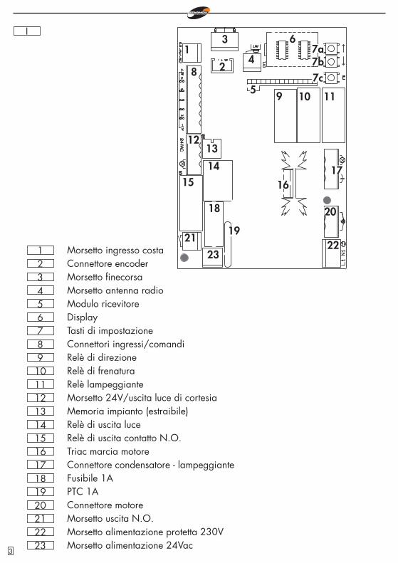
Tasti di impostazioneConnettori ingressi/comandiRelè di direzioneRelè di frenaturaRelè lampeggianteMorsetto 24V/uscita luce di cortesiaMemoria impianto (estraibile)Relè di uscita luceRelè di uscita contatto N.O.Triac marcia motoreConnettore condensatore - lampeggianteFusibile 1A
19 PTC 1A20 Connettore motore21 Morsetto uscita N.O.22 Morsetto alimentazione protetta 230V
654321
DisplayModulo ricevitoreMorsetto antenna radioMorsetto fi necorsaConnettore encoderMorsetto ingresso costa
1
20
19
18
171615
14
1312
11109
8
7a6
5
4
3
2 7b7c
2322
21
23 Morsetto alimentazione 24Vac3
I
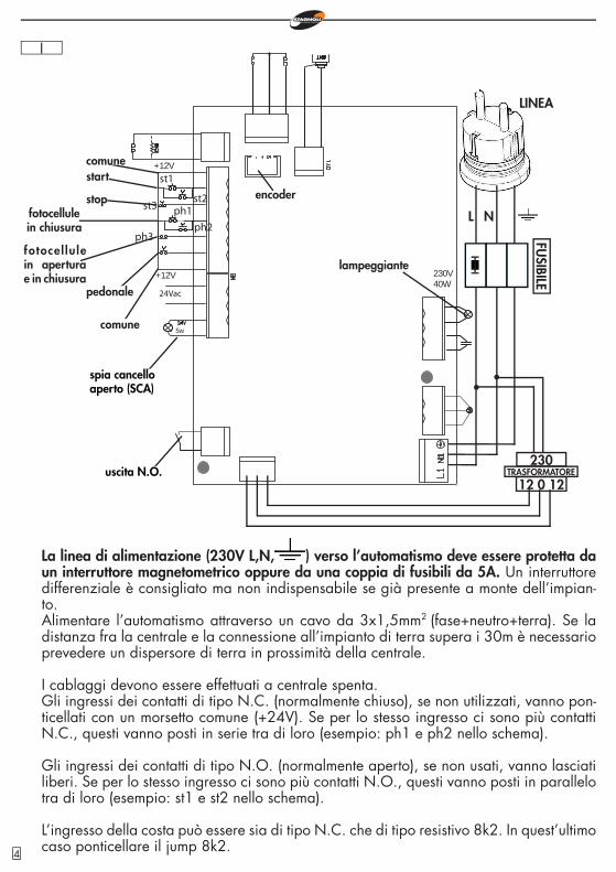
La linea di alimentazione (230V L,N, ) verso l’automatismo deve essere protetta da un interruttore magnetometrico oppure da una coppia di fusibili da 5A. Un interruttore differenziale è consigliato ma non indispensabile se già presente a monte dell’impian-to.Alimentare l’automatismo attraverso un cavo da 3x1,5mm2
(fase+neutro+terra). Se la distanza fra la centrale e la connessione all’impianto di terra supera i 30m è necessario prevedere un dispersore di terra in prossimità della centrale.
I cablaggi devono essere effettuati a centrale spenta.Gli ingressi dei contatti di tipo N.C. (normalmente chiuso), se non utilizzati, vanno pon-ticellati con un morsetto comune (+24V). Se per lo stesso ingresso ci sono più contatti N.C., questi vanno posti in serie tra di loro (esempio: ph1 e ph2 nello schema).
Gli ingressi dei contatti di tipo N.O. (normalmente aperto), se non usati, vanno lasciati liberi. Se per lo stesso ingresso ci sono più contatti N.O., questi vanno posti in parallelo tra di loro (esempio: st1 e st2 nello schema).
L’ingresso della costa può essere sia di tipo N.C. che di tipo resistivo 8k2. In quest’ultimo caso ponticellare il jump 8k2.
L N
spia cancello aperto (SCA)
uscita N.O.
LINEA
st1
st3
5w
24Vac
+12V
+12V
230V40W
ph1
ph3
st2
ph2
comunestart
stopfotocellulein chiusura
fotocel lulein apertura e in chiusura
pedonale
comune
lampeggiante
230
12 0 12TRASFORMATORE
FUSIBILE
encoder
4
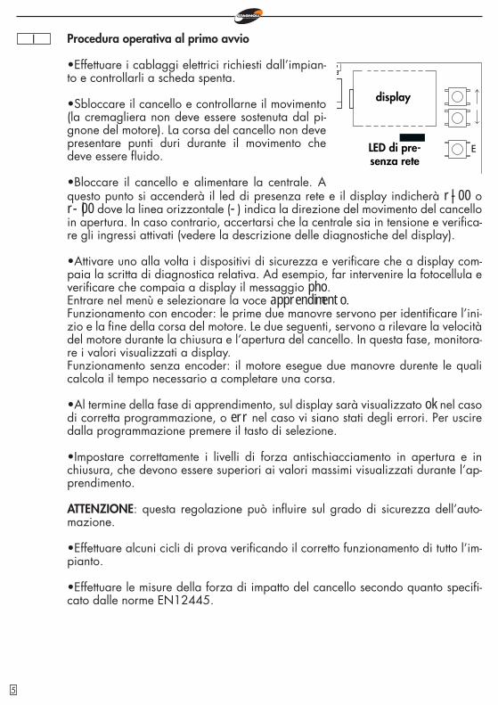
I Procedura operativa al primo avvio
•Effettuare i cablaggi elettrici richiesti dall’impian-to e controllarli a scheda spenta.
•Sbloccare il cancello e controllarne il movimento (la cremagliera non deve essere sostenuta dal pi-gnone del motore). La corsa del cancello non deve presentare punti duri durante il movimento che deve essere fl uido.
•Bloccare il cancello e alimentare la centrale. A
E
questo punto si accenderà il led di presenza rete e il display indicherà r|-00 o r-|00 dove la linea orizzontale (-) indica la direzione del movimento del cancello in apertura. In caso contrario, accertarsi che la centrale sia in tensione e verifi ca-re gli ingressi attivati (vedere la descrizione delle diagnostiche del display).
•Attivare uno alla volta i dispositivi di sicurezza e verifi care che a display com-paia la scritta di diagnostica relativa. Ad esempio, far intervenire la fotocellula e verifi care che compaia a display il messaggio pho.Entrare nel menù e selezionare la voce apprendimento.Funzionamento con encoder: le prime due manovre servono per identifi care l’ini-zio e la fi ne della corsa del motore. Le due seguenti, servono a rilevare la velocità del motore durante la chiusura e l’apertura del cancello. In questa fase, monitora-re i valori visualizzati a display.Funzionamento senza encoder: il motore esegue due manovre durente le quali calcola il tempo necessario a completare una corsa.
•Al termine della fase di apprendimento, sul display sarà visualizzato ok nel caso di corretta programmazione, o err nel caso vi siano stati degli errori. Per uscire dalla programmazione premere il tasto di selezione.
•Impostare correttamente i livelli di forza antischiacciamento in apertura e in chiusura, che devono essere superiori ai valori massimi visualizzati durante l’ap-prendimento.
ATTENZIONE: questa regolazione può infl uire sul grado di sicurezza dell’auto-mazione.
•Effettuare alcuni cicli di prova verifi cando il corretto funzionamento di tutto l’im-pianto.
•Effettuare le misure della forza di impatto del cancello secondo quanto specifi -cato dalle norme EN12445.
display
LED di pre-senza rete
5
I
r|-00
agg. radioc.
1ch
regolazioni
ttca
funzioni
ca
ba
fm1a
fm1c
bp
cr
2p
pl
re
ss
it
cfal
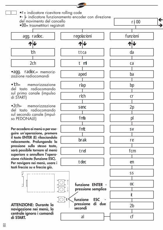
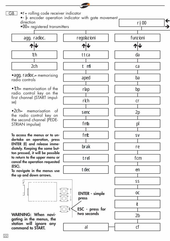
•agg. radioc.= memoriz-zazione radiocomandi
•1ch= memorizzazione del tasto radiocomando sul primo canale (impulso di START)
•2ch= memorizzazione del tasto radiocomando sul secondo canale (impul-so PEDONALE)
Per accedere ai menù o per ese-guire un’operazione, premere il tasto ENTER (E) rilasciandolo velocemente. Prolungando la pressione sullo stesso tasto, sarà possibile tornare al menù superiore o annullare l’opera-zione richiesta (funzione ESC).Per navigare nei menù, usare i tasti freccia su e freccia giù.
E
•r= indicatore ricevitore rolling code•-|= indicatore funzionamento encoder con direzione del movimento del cancello•00= trasmettitori registrati
ATTENZIONE: Durante la navigazione nei menù, la centrale ignora i comandi di START.
t m1
da
fcm
2b
2ch
funzione ENTER - pressione semplice
funzione ESC - pressione di due secondi
sv
en
oc
aped
senc
brak
trel
tdec
rlap
rlch
6
I
00
cancella
reset parametri
cancella 1 radiocomando
lingua
italiano
english
apprendimento
leggi codice
cancella tutta memoria radio
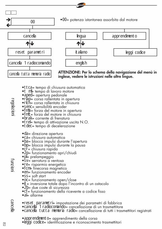
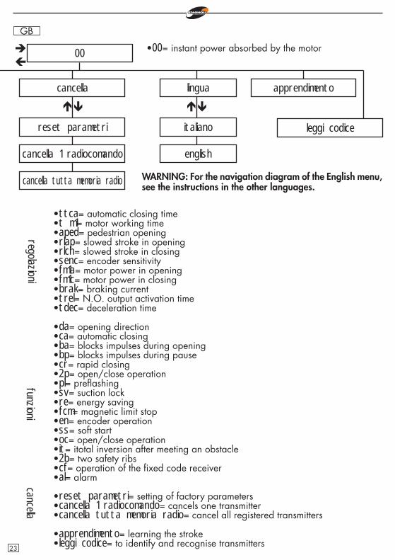
•ttca= tempo di chiusura automatica•t m1= tempo di lavoro motore•aped= apertura pedonale•rlap= corsa rallentata in apertura•rlch= corsa rallentata in chiusura•senc= sensibilità encoder•fm1a= forza del motore in apertura•fm1c= forza del motore in chiusura•brak= corrente di frenatura•trel= tempo di attivazione uscita N.O.•tdec= tempo di decelerazione
•da= direzione apertura•ca= chiusura automatica•ba= blocca impulsi durante l’apertura•bp= blocca impulsi durante la pausa•cr= chiusura rapida•2p= funzionamento apri/chiudi•pl= prelampeggio•sv= serratura a ventosa•re= risparmio energetico•fcm= fi necorsa magnetico•en= funzionamento encoder•ss= soft start•oc= funzionamento open/close•it= inversione totale dopo l’incontro di un ostacolo•2b= due coste di sicurezza•cf= funzionamento della ricevente a codice fi sso•al= allarme
•reset parametri= impostazione dei parametri di fabbrica•cancella 1 radiocomando= cancellazione di un trasmettitore•cancella tutta memoria radio= cancellazione di tutti i trasmettitori registrati
•apprendimento= apprendimento della corsa•leggi codice= identifi cazione e riconoscimento trasmettitori
regolazionifunzioni
•00= potenza istantanea assorbita dal motore
cancella
ATTENZIONE: Per lo schema della navigazione del menù in inglese, vedere le istruzioni nelle altre lingue.
7
I Aggiunta radiocomandi•Prima di memorizzare un trasmettitore, assicurarsi che sia compatibile con la tipologia di ricevitore integrato (nella prima visualizzazione del display apparirà r, se si tratta di un ricevitore in modalità rolling code o f se si tratta di un ricevitore in modalità codice fi sso). Il ricevitore può memorizzare codici rolling code di tipo HCS300 STAGNOLI con miliardi di combinazioni o codici fi ssi di tipo HT53200 a 13 bit o la parte fi ssa di un codice rolling code (28 bit SN). É possibile memo-rizzare fi no a 76 codici.
•Entrando nel menù agg. radioc., portarsi sulla scritta a display 1ch o 2ch e sceglie-re il canale che si vuole aggiungere. Schiacciando ENTER, verrà poi visualizzata la scritta premi che chiede di schiacciare il tasto che si desidera memorizzare. A questo punto il display visualizzerà la scritta ok se l’operazione viene portata a termine in maniera corretta, err nel caso si verifi chino errori di registrazione o full se la memoria del ricevitore è piena.
•Installando un’antenna esternamente alla centrale e lontana dal suolo, l’area di visibilità tra trasmettitori e centrale aumenta. Ricordarsi, inoltre, che parti me-talliche e cemento armato, se posti tra la centrale e il ricevitore, diminuiscono la capacità di ricezione di quest’ultimo.
Regolazioni•ttca (tempo di chiusura automatica)= è il tempo che intercorre tra l’apertura completa del cancello e la sua chiusura che avviene in modo automatico. Se la fotocellula è occupata, il tempo di ttca viene conteggiato dal momento in cui la fotocellula si disimpegna. Il tempo impostato di default da Stagnoli è 10sec ed è regolabile da 1 a 240sec.
•tm 1 (tempo di lavoro motore)= è il tempo di lavoro massimo del motore in aper-tura e in chiusura. Per una maggiore sicurezza regolare questo parametro in ma-niera che risulti leggermente superiore al tempo realmente impiegato dal cancello per completare la singola manovra. Il tempo impostato di default da Stagnoli è 120sec ed è regolabile da 5 a 240sec.
•aped (apertura pedonale)= è la lunghezza della corsa espressa in centimetri dell’apertura parziale, ossia della modalità pedonale. Il valore impostato di de-fault da Stagnoli è 70 ed è regolabile da 30 a 150.
•rlap (corsa rallentata in apertura)= la centrale rallenta la corsa del motore nella parte fi nale della sua fase di apertura. La corsa impostato di default da Stagnoli è 0cm ed è regolabile da 0 a 70cm. Con rlap=0 non vi è alcun rallentamento.N.B: Durante le fasi di rallentamento, il motore lavora a 1/3 della sua velocità nominale. Durante questa fase, la forza applicata al motore è ridotta e non è regolabile.
•rlch (corsa rallentata in chiusura)= la centrale rallenta la corsa del motore nella parte fi nale della sua fase di chiusura. La corsa impostato di default da Stagnoli è 0cm ed è regolabile da 0 a 70cm. Con rlch=0 non vi è alcun rallentamento.N.B: Durante le fasi di rallentamento, il motore lavora a 1/3 della sua velocità
8
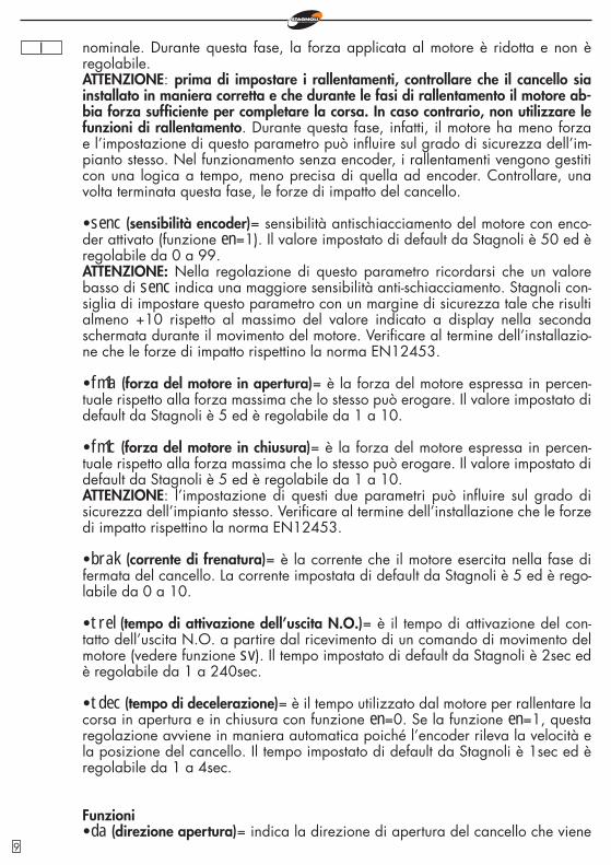
I nominale. Durante questa fase, la forza applicata al motore è ridotta e non è regolabile.ATTENZIONE: prima di impostare i rallentamenti, controllare che il cancello sia installato in maniera corretta e che durante le fasi di rallentamento il motore ab-bia forza suffi ciente per completare la corsa. In caso contrario, non utilizzare le funzioni di rallentamento. Durante questa fase, infatti, il motore ha meno forza e l’impostazione di questo parametro può infl uire sul grado di sicurezza dell’im-pianto stesso. Nel funzionamento senza encoder, i rallentamenti vengono gestiti con una logica a tempo, meno precisa di quella ad encoder. Controllare, una volta terminata questa fase, le forze di impatto del cancello.
•senc (sensibilità encoder)= sensibilità antischiacciamento del motore con enco-der attivato (funzione en=1). Il valore impostato di default da Stagnoli è 50 ed è regolabile da 0 a 99.ATTENZIONE: Nella regolazione di questo parametro ricordarsi che un valore basso di senc indica una maggiore sensibilità anti-schiacciamento. Stagnoli con-siglia di impostare questo parametro con un margine di sicurezza tale che risulti almeno +10 rispetto al massimo del valore indicato a display nella seconda schermata durante il movimento del motore. Verifi care al termine dell’installazio-ne che le forze di impatto rispettino la norma EN12453.
•fm1a (forza del motore in apertura)= è la forza del motore espressa in percen-tuale rispetto alla forza massima che lo stesso può erogare. Il valore impostato di default da Stagnoli è 5 ed è regolabile da 1 a 10.
•fm1c (forza del motore in chiusura)= è la forza del motore espressa in percen-tuale rispetto alla forza massima che lo stesso può erogare. Il valore impostato di default da Stagnoli è 5 ed è regolabile da 1 a 10.ATTENZIONE: l’impostazione di questi due parametri può infl uire sul grado di sicurezza dell’impianto stesso. Verifi care al termine dell’installazione che le forze di impatto rispettino la norma EN12453.
•brak (corrente di frenatura)= è la corrente che il motore esercita nella fase di fermata del cancello. La corrente impostata di default da Stagnoli è 5 ed è rego-labile da 0 a 10.
•trel (tempo di attivazione dell’uscita N.O.)= è il tempo di attivazione del con-tatto dell’uscita N.O. a partire dal ricevimento di un comando di movimento del motore (vedere funzione sv). Il tempo impostato di default da Stagnoli è 2sec ed è regolabile da 1 a 240sec.
•tdec (tempo di decelerazione)= è il tempo utilizzato dal motore per rallentare la corsa in apertura e in chiusura con funzione en=0. Se la funzione en=1, questa regolazione avviene in maniera automatica poiché l’encoder rileva la velocità e la posizione del cancello. Il tempo impostato di default da Stagnoli è 1sec ed è regolabile da 1 a 4sec.
Funzioni•da (direzione apertura)= indica la direzione di apertura del cancello che viene
9
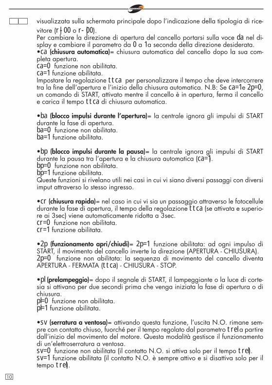
I visualizzata sulla schermata principale dopo l’indicazione della tipologia di rice-vitore (r|-00 o r-|00).Per cambiare la direzione di apertura del cancello portarsi sulla voce da nel di-splay e cambiare il parametro da 0 a 1 a seconda della direzione desiderata.•ca (chiusura automatica)= chiusura automatica del cancello dopo la sua com-pleta apertura.ca=0 funzione non abilitata.ca=1 funzione abilitata.Impostare la regolazione ttca per personalizzare il tempo che deve intercorrere tra la fi ne dell’apertura e l’inizio della chiusura automatica. N.B: Se ca=1 e 2p=0, un comando di START, attivato mentre il cancello è in apertura, ferma il cancello e carica il tempo ttca di chiusura automatica.
•ba (blocco impulsi durante l’apertura)= la centrale ignora gli impulsi di START durante la fase di apertura.ba=0 funzione non abilitata.ba=1 funzione abilitata.
•bp (blocco impulsi durante la pausa)= la centrale ignora gli impulsi di START durante la pausa tra l’apertura e la chiusura automatica (ca=1).bp=0 funzione non abilitata.bp=1 funzione abilitata.Queste funzioni si rivelano utili nei casi in cui vi siano diversi passaggi con diversi imput attraverso lo stesso ingresso.
•cr (chiusura rapida)= nel caso in cui vi sia un passaggio attraverso le fotocellule durante la fase di apertura, il tempo della regolazione ttca (se attivata e superio-re ai 3sec) viene automaticamente ridotta a 3sec.cr=0 funzione non abilitata.cr=1 funzione abilitata.
•2p (funzionamento apri/chiudi)= 2p=1 funzione abilitata: ad ogni impulso di START, il movimento del cancello inverte la direzione (APERTURA - CHIUSURA).2p=0 funzione non abilitata: la sequenza di movimento del cancello diventa APERTURA - FERMATA (ttca) - CHIUSURA - STOP.
•pl (prelampeggio)= dopo il segnale di START, il lampeggiante o la luce di corte-sia si attivano per due secondi prima che venga iniziata la fase di apertura o di chiusura.pl=0 funzione non abilitata.pl=1 funzione abilitata.
•sv (serratura a ventosa)= attivando questa funzione, l’uscita N.O. rimane sem-pre con contatto chiuso, fuorché per il tempo regolato dal parametro trel a partire dall’inizio del movimento del motore. Questa modalità gestisce il funzionamento di un’elettroserratura a ventosa.sv=0 funzione non abilitata (il contatto N.O. si attiva solo per il tempo trel).sv=1 funzione abilitata (il contatto N.O. è sempre attivo e si disattiva solo per il tempo trel).
10
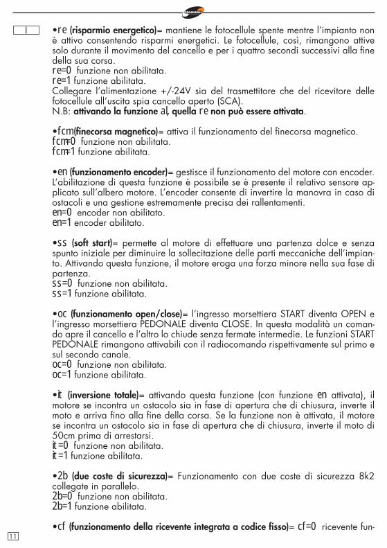
I •re (risparmio energetico)= mantiene le fotocellule spente mentre l’impianto non è attivo consentendo risparmi energetici. Le fotocellule, così, rimangono attive solo durante il movimento del cancello e per i quattro secondi successivi alla fi ne della sua corsa.re=0 funzione non abilitata.re=1 funzione abilitata.Collegare l’alimentazione +/-24V sia del trasmettitore che del ricevitore delle fotocellule all’uscita spia cancello aperto (SCA).N.B: attivando la funzione al, quella re non può essere attivata.
•fcm (fi necorsa magnetico)= attiva il funzionamento del fi necorsa magnetico.fcm=0 funzione non abilitata.fcm=1 funzione abilitata.
•en (funzionamento encoder)= gestisce il funzionamento del motore con encoder. L’abilitazione di questa funzione è possibile se è presente il relativo sensore ap-plicato sull’albero motore. L’encoder consente di invertire la manovra in caso di ostacoli e una gestione estremamente precisa dei rallentamenti.en=0 encoder non abilitato.en=1 encoder abilitato.
•ss (soft start)= permette al motore di effettuare una partenza dolce e senza spunto iniziale per diminuire la sollecitazione delle parti meccaniche dell’impian-to. Attivando questa funzione, il motore eroga una forza minore nella sua fase di partenza.ss=0 funzione non abilitata.ss=1 funzione abilitata.
•oc (funzionamento open/close)= l’ingresso morsettiera START diventa OPEN e l’ingresso morsettiera PEDONALE diventa CLOSE. In questa modalità un coman-do apre il cancello e l’altro lo chiude senza fermate intermedie. Le funzioni START PEDONALE rimangono attivabili con il radiocomando rispettivamente sul primo e sul secondo canale.oc=0 funzione non abilitata.oc=1 funzione abilitata.
•it (inversione totale)= attivando questa funzione (con funzione en attivata), il motore se incontra un ostacolo sia in fase di apertura che di chiusura, inverte il moto e arriva fi no alla fi ne della corsa. Se la funzione non è attivata, il motore se incontra un ostacolo sia in fase di apertura che di chiusura, inverte il moto di 50cm prima di arrestarsi.it=0 funzione non abilitata.it=1 funzione abilitata.
•2b (due coste di sicurezza)= Funzionamento con due coste di sicurezza 8k2 collegate in parallelo.2b=0 funzione non abilitata.2b=1 funzione abilitata.
•cf (funzionamento della ricevente integrata a codice fi sso)= cf=0 ricevente fun-11
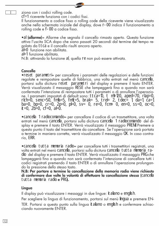
I ziona con i codici rolling code.cf=1 ricevente funziona con i codici fi ssi.Il funzionamento a codice fi sso o rolling code della ricevente viene visualizzato anche nella schermata iniziale del display, dove r-00 indica il funzionamento a rolling code e f-00 a codice fi sso.
•al (allarme)= Allarme che segnala il cancello rimasto aperto. Questa funzione attiva l’uscita SCA dopo che siano passati 20 secondi dal termine del tempo re-golato da ttca e il cancello risulti ancora aperto.al=0 funzione non abilitata.al=1 funzione abilitata.N.B: attivando la funzione al, quella re non può essere attivata.
Cancella•reset parametri= per cancellare i parametri delle regolazioni e delle funzioni regolate e reimpostare quelle di fabbrica, una volta entrati nel menù cancella, portarsi sulla dicitura reset parametri del display e premere il tasto ENTER. Verrà visualizzato il messaggio RESE che lampeggerà fi no a quando non sarà confermata l’intenzione di reimpostare tutti i parametri o di annullare l’operazio-ne. I parametri impostati di default sono: ttca=10, t m1=120, aped=70, rlap=0, rlch=0, senc=50, fm1a=5, fm1c=5, brak= 5, trel= 2, tdec= 1, da=1, ca=1, ba=0, bp=0, cr=0, 2p=0, pl=0, sv= 0, re=0, fcm= 0, en=0, ss=0, oc=0, it=0, 2b=0, cf=0, al=0.
•cancella 1 radiocomando= per cancellare il codice di un trasmettitore, una volta entrati nel menù cancella, portarsi sulla dicitura cancella 1 radiocomando del di-splay e premere il tasto ENTER. Verrà visualizzato il messaggio PREMI. Premere a questo punto il tasto del trasmettitore da cancellare. Se l’operazione sarà portata a termine in maniera corretta, verrà visualizzato il messaggio OK. In caso contra-rio, ERR.
•cancella tutta memoria radio= per cancellare tutti i trasmettitori registrati, una volta entrati nel menù cancella, portarsi sulla dicitura cancella tutta memoria ra-dio del display e premere il tasto ENTER. Verrà visualizzato il messaggio PRG che lampeggerà fi no a quando non sarà confermata l’intenzione di cancellare tutti i codici registrati premendo il tasto ENTER o di annullare l’operazione prolungan-do la pressione dello stesso tasto.N.B: Per portare a termine la cancellazione della memoria radio viene richiesto di confermare due volte la volontà di effettuare la cancellazione stessa (cancella tutta memoria radio e PRG).
LinguaIl display può visualizzare i messaggi in due lingue: italiano e english.Per scegliere la lingua di funzionamento, portarsi sul menù lingua e premere EN-TER. Portarsi a questo punto sulla lingua italiano o english e confermare schiac-ciando nuovamente ENTER.
12
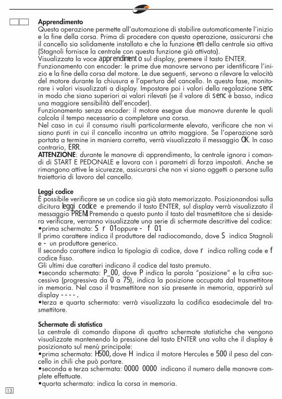
I ApprendimentoQuesta operazione permette all’automazione di stabilire automaticamente l’inizio e la fi ne della corsa. Prima di procedere con questa operazione, assicurarsi che il cancello sia solidamente installato e che la funzione en della centrale sia attiva (Stagnoli fornisce la centrale con questa funzione già attivata).Visualizzata la voce apprendimento sul display, premere il tasto ENTER.Funzionamento con encoder: le prime due manovre servono per identifi care l’ini-zio e la fi ne della corsa del motore. Le due seguenti, servono a rilevare la velocità del motore durante la chiusura e l’apertura del cancello. In questa fase, monito-rare i valori visualizzati a display. Impostare poi i valori della regolazione senc in modo che siano superiori ai valori rilevati (se il valore di senc è basso, indica una maggiore sensibilità dell’encoder).Funzionamento senza encoder: il motore esegue due manovre durente le quali calcola il tempo necessario a completare una corsa.Nel caso in cui il consumo risulti particolarmente elevato, verifi care che non vi siano punti in cui il cancello incontra un attrito maggiore. Se l’operazione sarà portata a termine in maniera corretta, verrà visualizzato il messaggio OK. In caso contrario, ERR.ATTENZIONE: durante le manovre di apprendimento, la centrale ignora i coman-di di START E PEDONALE e lavora con i parametri di forza impostati. Anche se rimangono attive le sicurezze, assicurarsi che non vi siano oggetti o persone sulla traiettoria di lavoro del cancello.
Leggi codiceÈ possibile verifi care se un codice sia già stato memorizzato. Posizionandosi sulla dicitura leggi codice e premendo il tasto ENTER, sul display verrà visualizzato il messaggio PREMI. Premendo a questo punto il tasto del trasmettitore che si deside-ra verifi care, verranno visualizzate una serie di schermate descrittive del codice:•prima schermata: S r 01 oppure - f 01.Il primo carattere indica il produttore del radiocomando, dove S indica Stagnoli e - un produttore generico.Il secondo carattere indica la tipologia di codice, dove r indica rolling code e f codice fi sso.Gli ultimi due caratteri indicano il codice del tasto premuto.•seconda schermata: P_00, dove P indica la parola “posizione” e la cifra suc-cessiva (progressiva da 0 a 75), indica la posizione occupata dal trasmettitore in memoria. Nel caso il trasmettitore non sia presente in memoria, apparirà sul display ----.•terza e quarta schermata: verrà visualizzata la codifi ca esadecimale del tra-smettitore.
Schermate di statisticaLa centrale di comando dispone di quattro schermate statistiche che vengono visualizzate mantenendo la pressione del tasto ENTER una volta che il display è posizionato sul menù principale:•prima schermata: H500, dove H indica il motore Hercules e 500 il peso del can-cello in chili che può portare.•seconda e terza schermata: 0000 0000 indicano il numero delle manovre com-plete effettuate.•quarta schermata: indica la corsa in memoria.
13
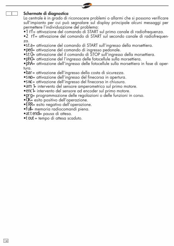
I Schermate di diagnosticaLa centrale è in grado di riconoscere problemi o allarmi che si possono verifi care sull’impianto per cui può segnalare sul display principale alcuni messaggi per permettere l’individuazione del problema:•1 rf= attivazione del comando di START sul primo canale di radiofrequenza.•2 rf= attivazione del comando di START sul secondo canale di radiofrequen-za.•sta= attivazione del comando di START sull’ingresso della morsettiera.•ped= attivazione del comando di ingresso pedonale.•stO= attivazione del il comando di STOP sull’ingresso della morsettiera.•phO= attivazione del l’ingresso delle fotocellule sulla morsettiera.•phA= attivazione dell’ingresso delle fotocellule sulla morsettiera in fase di aper-tura.•bar= attivazione dell’ingresso della costa di sicurezza.•swo= attivazione dell’ingresso del fi necorsa in apertura.•swc= attivazione dell’ingresso del fi necorsa in chiusura.•am 1= intervento del sensore amperometrico sul primo motore.•enc1= intervento del sensore ad encoder sul primo motore.•prg= programmazione delle regolazioni o delle funzioni in corso.•OK= esito positivo dell’operazione.•ERR= esito negativo dell’operazione.•full= memoria radiocomandi piena.•attendi= pausa di attesa.•tout= tempo di attesa scaduto.
14
I
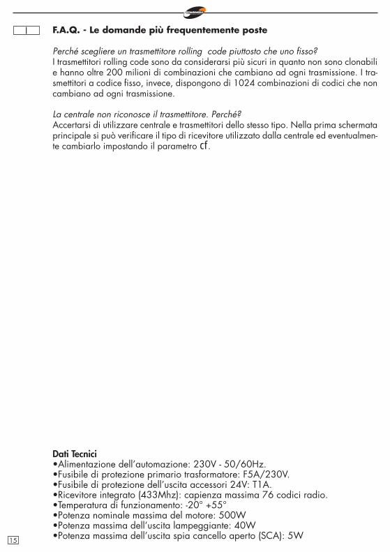
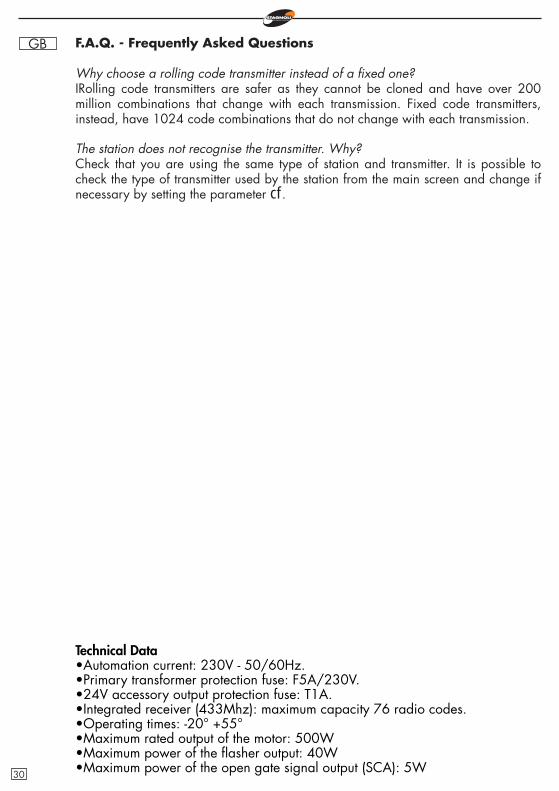
Dati Tecnici•Alimentazione dell’automazione: 230V - 50/60Hz.•Fusibile di protezione primario trasformatore: F5A/230V.•Fusibile di protezione dell’uscita accessori 24V: T1A.•Ricevitore integrato (433Mhz): capienza massima 76 codici radio.•Temperatura di funzionamento: -20° +55°•Potenza nominale massima del motore: 500W•Potenza massima dell’uscita lampeggiante: 40W•Potenza massima dell’uscita spia cancello aperto (SCA): 5W
F.A.Q. - Le domande più frequentemente poste
Perché scegliere un trasmettitore rolling code piuttosto che uno fi sso?I trasmettitori rolling code sono da considerarsi più sicuri in quanto non sono clonabili e hanno oltre 200 milioni di combinazioni che cambiano ad ogni trasmissione. I tra-smettitori a codice fi sso, invece, dispongono di 1024 combinazioni di codici che non cambiano ad ogni trasmissione.
La centrale non riconosce il trasmettitore. Perché?Accertarsi di utilizzare centrale e trasmettitori dello stesso tipo. Nella prima schermata principale si può verifi care il tipo di ricevitore utilizzato dalla centrale ed eventualmen-te cambiarlo impostando il parametro cf.
15
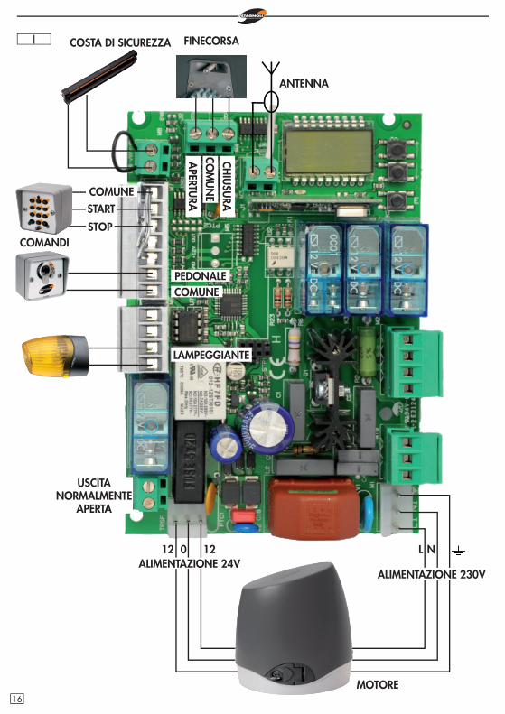
I COSTA DI SICUREZZA
COMANDI
COMUNEPEDONALE
LAMPEGGIANTE
012 12 L N
FINECORSA
MOTORE
COMUNE
STOP
START
CHIU
SURA
COM
UN
EA
PERTURA
ANTENNA
ALIMENTAZIONE 24VALIMENTAZIONE 230V
USCITANORMALMENTE
APERTA
16

I
ENCO
DER
MO
TORE
LAMPEGGIANTE
CONDENSATORE
CHIUSURACOMUNEAPERTURA
FOTO
CELL
ULE
IN
CH
IUSU
RAFO
TOCE
LLU
LE
IN A
PERT
URA
TXRX
RXTX
ALIMENTAZIONE FOTOCELLULE
COMUNE
FOTOCELLULE IN CHIUSURAFOTOCELLULE IN APERTURA E IN CHIUSURA
17
GB The Stagnoli H230 is the control station that has been studied for Hercules 230V automation.
Made using only prime quality materials, it has been planned for low absorption at rest allowing a low consumption of electricity.Particular attention has been paid to professionals in the sector by making it easier to programme the station by using a multi-language display.
WARNINGS AND SAFETY REGULATIONS
•This manual has been created by Stagnoli for specifi c use by pro-fessional and qualifi ed staff.
•It is advisable to read the instruction manual right through before proceeding with installation.
•During wiring the system must not be live.
•Automatic gate systems must be installed by qualifi ed technical staff in compliance with legal requirements.
•DOUBLE SAFETY: The station has two safety sensors: one with en-coder and the other is amperometric.
•Before installing check that the gate is fi rm, well fi xed and has measurements, dimensions and fi xings that are suitable for Hercu-les automation.
Inform the end user precisely of the method of use, residual dangers, the need for maintenance and the need to check safety devices at least once every six months.
18
GB
789
101112131415161718
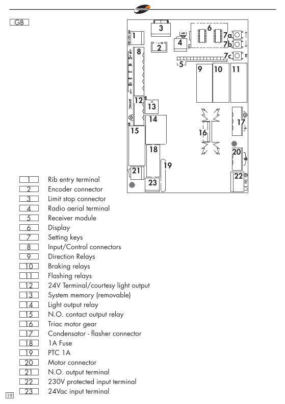
Setting keysInput/Control connectorsDirection RelaysBraking relaysFlashing relays24V Terminal/courtesy light outputSystem memory (removable)Light output relayN.O. contact output relayTriac motor gearCondensator - fl asher connector1A Fuse
19 PTC 1A20 Motor connector21 N.O. output terminal22 230V protected input terminal
654321
DisplayReceiver moduleRadio aerial terminal Limit stop connectorEncoder connectorRib entry terminal
1
20
19
18
171615
14
1312
11109
8
7a6
5
4
3
2 7b7c
2322
21
23 24Vac input terminal19
GB
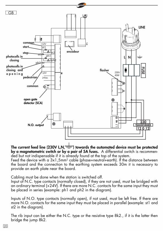
The current feed line (230V L,N, ) towards the automated device must be protected by a magnetometric switch or by a pair of 5A fuses. A differential switch is recommen-ded but not indispensable if it is already found at the top of the system.Feed the device with a 3x1,5mm2 cable (phase+neutral+earth). If the distance between the board and the connection to the earthing system exceeds 30m it is necessary to provide an earth plate near the board.
Cabling must be done when the station is switched off.Input of N.C. type contacts (normally closed), if they are not used, must be bridged with an ordinary terminal (+24V). If there are more N.C. contacts for the same input they must be placed in series (example: ph1 and ph2 in the diagram).
Inputs of N.O. type contacts (normally open), if not used, must be left free. If there are more N.O. contacts for the same input they must be placed in parallel (example: st1 and st2 in the diagram).
The rib input can be either the N.C. type or the resistive type 8k2., if it is the latter then bridge the jump 8k2.
L N
open gate detector (SCA)
N.O. output
LINE
st1
st3
5w
24Vac
+12V
+12V
230V40W
ph1
ph3
st2
ph2
commonstart
stopphotocells in
closing
photocells in closing and o p e n i n g
pedestrian
common
fl asher
230
12 0 12TRANSFORMER
FUSE
encodeur
20
GB Operating procedure at the fi rst start up
•Undertake the electric wiring for the plant and check when the card is switched off.
•Unblock the gate and check its movement (the rack must not be supported by the motor pinion). The stroke of the gate must not have any areas of stiffness during movement, it must be smooth.
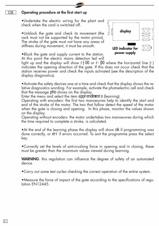
•Block the gate and supply current to the station. At this point the electric mains detection led will
E
light up and the display will show r|-00 or r-|00 where the horizontal line (-) indicates the opening direction of the gate. If this does not occur check that the station receives power and check the inputs activated (see the description of the display diagnostics).
•Activate the safety devices one at a time and check that the display shows the re-lative diagnostics wording. For example, activate the photoelectric cell and check that the message pho shows on the display.Enter the menu and select the item apprendimento (learning).Operating with encoders: the fi rst two manoeuvres help to identify the start and end of the stroke of the motor. The two that follow detect the speed of the motor when the gate is closing and opening. In this phase, monitor the values shown on the display.Operating without encoders: the motor undertakes two manoeuvres during which the time required to complete a stroke, is calculated.
•At the end of the learning phase the display will show ok if programming was done correctly, or err if errors occurred. To exit the programme press the select key.
•Correctly set the levels of anti-crushing force in opening and in closing, these must be greater than the maximum values viewed during learning.
WARNING: this regulation can infl uence the degree of safety of an automated device.
•Carry out some test cycles checking the correct operation of the entire system.
•Measure the force of impact of the gate according to the specifi cations of regu-lation EN12445.
display
LED indicator for power supply
21
GB
r|-00
agg. radioc.
1ch
regolazioni
ttca
funzioni
ca
ba
fm1a
fm1c
bp
cr
2p
pl
re
ss
it
cfal
•agg. radioc.= memorising radio controls
•1ch= memorisation of the radio control key on the fi rst channel (START impul-se)
•2ch= memorisation of the radio control key on the second channel (PEDE-STRIAN impulse)
To access the menus or to un-dertake an operation, press ENTER (E) and release imme-diately. Keeping the same but-ton pressed, it will be possible to return to the upper menu or cancel the operation requested (ESC).To navigate in the menus use the up and down arrows.
E
•r= rolling code receiver indicator•-|= encoder operation indicator with gate movement direction•00= registered transmitters
WARNING: When navi-gating in the menus, the station will ignore any command to START.
t m1
da
fcm
2b
2ch
ENTER - simple press
ESC - press for two seconds
sv
en
oc
aped
senc
brak
trel
tdec
rlap
rlch
22
GB
00
cancella
reset parametri
cancella 1 radiocomando
lingua
italiano
english
apprendimento
leggi codice
cancella tutta memoria radio
•ttca= automatic closing time•t m1= motor working time•aped= pedestrian opening •rlap= slowed stroke in opening•rlch= slowed stroke in closing•senc= encoder sensitivity•fm1a= motor power in opening•fm1c= motor power in closing•brak= braking current•trel= N.O. output activation time•tdec= deceleration time
•da= opening direction•ca= automatic closing•ba= blocks impulses during opening•bp= blocks impulses during pause•cr= rapid closing•2p= open/close operation•pl= prefl ashing•sv= suction lock•re= energy saving•fcm= magnetic limit stop•en= encoder operation•ss= soft start•oc= open/close operation•it= itotal inversion after meeting an obstacle•2b= two safety ribs•cf= operation of the fi xed code receiver•al= alarm
•reset parametri= setting of factory parameters•cancella 1 radiocomando= cancels one transmitter•cancella tutta memoria radio= cancel all registered transmitters
•apprendimento= learning the stroke•leggi codice= to identify and recognise transmitters
regolazionifunzioni
•00= instant power absorbed by the motor
cancella
WARNING: For the navigation diagram of the English menu, see the instructions in the other languages.
23
GB Addition of radiocontrols•Before memorising a transmitter make sure that it is compatible with the type of receiver that is integrated (the fi rst time the display shows r, if the receiver is in rolling code mode, or f if the receiver is in fi xed code mode). The receiver can memorise rolling codes type HCS300 STAGNOLI with billions of combinations or fi xed codes type HT53200 with 13 bits or the fi xed part of a rolling code (28 bit SN). It is possible to memorise up to 76 codes.
•Enter the menu agg. radioc., move over the wording display 1ch or 2ch and select the channel that is to be added. Press ENTER, the wording press will ap-pear to press the key that must be memorised. At this point the display shows the wording ok if the operation has been done correctly, err if there are registration errors or full if the receiver memory is full.
•An external antenna installed far from the ground, increases the visibility betwe-en the transmitter and the receiver. The power of the receiver can be reduced if metal parts or reinforced concrete are placed next to it.
Regulating•ttca (automatic closing time)= this is the time from the when the gate is opened fully to when it is closed automatically. If the photoelectric cell is engaged, the ttca time is counted from the time when the photoelectric cell is freed. The default time set by Stagnoli is 10 secs and it can be regulated from 1 to 240secs.
•tm 1 (motor working time)= this is the maximum work time of the motor when opening and closing. For greater safety regulate this parameter so that it is slightly above the time it really takes for the gate to complete a single manoeuvre. The de-fault time set by Stagnoli is 120 secs and it can be regulated from 5 to 240secs.
•aped (pedestrian opening)= this is the length of the stroke stated in centimetres of the partial opening, namely the pedestrian mode. The default value set by Sta-gnoli is 70 secs and it can be regulated from 30 to 150.
•rlap (slowed stroke in opening)= the station slows down the stroke of the motor in the end part of its opening phase. The default stroke set by Stagnoli is 0 cm and it can be regulated from 0 to 70 cm. With rlap=0 there is no slowing down.N.B: In slowing phase, the motor works with 1/3 of its nominal speed. In this phase, the force, applied on the motor is reduced and not adjustable.
•rlch (slowed stroke in closing)= the station slows down the stroke of the motor in the end part of its closing phase. The default stroke set by Stagnoli is 0 cm and it can be regulated from 0 to 70 cm. With rlch=0 there is no slowing down.N.B: In slowing phase, the motor works with 1/3 of its nominal speed. In this phase, the force, applied on the motor is reduced and not adjustable.WARNING: before setting the slowing phase check that the gate has been installed correctly and that during the slowing down phases the motor has enough power to complete the stroke. If this is not the case do not use slowing down functions. In this phase, the motor has less power and the way this parameter is set can infl uen-ce the level of safety of the system itself. When operating without encoder, slowing
24
GB down is run with a time logic that is less precise than one with an encoder. Once this phase has been done, check the force of impact of the gate.•senc (encoder sensitivity)= anti-crushing sensitivity of the motor with encoder activated (en=1 function). The default value set by Stagnoli is 50 and it can be regulated from 0 to 99.WARNING: In regulating this parameter remember that a low senc value indica-tes greater anti-crushing sensitivity. Stagnoli advises setting this parameter with a safety margin that is at least +10 compared with the maximum value shown on the display in the second screen during the movement of the motor. At the end of installation check that the force of impact is in compliance with the regulation EN12453.
•fm1a (force of the motor in opening)= is the force of the motor stated in percen-tage compared with the maximum force that the same can generate. The default value set by Stagnoli is 5 and it can be regulated from 1 to 10.
•fm1c (force of the motor in closing)= is the force of the motor stated in percentage compared with the maximum force that the same can generate. The default value set by Stagnoli is 5 and it can be regulated from 1 to 10.WARNING: the setting of these two parameters can infl uence the level of safety of the system itself. At the end of installation check that the force of impact is in compliance with the regulation EN12453.
•brak (braking current)= this is the current that the motor exercises in the gate stopping phase. The default current set by Stagnoli is 5 and it can be regulated from 0 to 10.
•trel (N.O. exit activation time)= it is the N.O. exit activation time from the receipt of the motor movement command (see sv function). The default time set by Stagno-li is 2 secs and it can be regulated from 1 to 240secs.
•tdec (deceleration time)= it is the time used by the motor to slow down the stroke when opening and closing with en=0 function. If the function en=1, this regulation comes about automatically as the encoder reads the speed and position of the gate. The default time set by Stagnoli is 1 sec and it can be regulated from 1 to 4 secs.
Functions•da (opening direction)= indicates the opening direction of the gate that is viewed on the main screen after the indicating the type of receiver (r|-00 or r-|00).To change the gate opening direction go to da on the display and change the parameter from 0 to 1 depending on the desired direction.
•ca (automatic closing)= automatic closing of the gate after it has opened com-pletely.ca=0 function not enabled.ca=1 function enabled.Set the ttca regulation to customise the time that must pass from the end of ope-ning and the start of automatic closing. N.B: If ca=1 and 2p=0, the command to
25
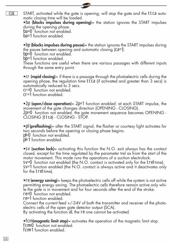
GB START, activated while the gate is opening, will stop the gate and the ttca auto-matic closing time will be loaded.•ba (blocks impulses during opening)= the station ignores the START impulses during the opening phase.ba=0 function not enabled.ba=1 function enabled.
•bp (blocks impulses during pause)= the station ignores the START impulses during the pause between opening and automatic closing (ca=1).bp=0 function not enabled.bp=1 function enabled.These functions are useful when there are various passages with different inputs through the same entry point.
•cr (rapid closing)= if there is a passage through the photoelectric cells during the opening phase, the regulation time ttca (if activated and greater than 3 secs) is automatically reduced to 3 secs.cr=0 function not enabled.cr=1 function enabled.
•2p (open/close operation)= 2p=1 function enabled: at each START impulse, the movement of the gate changes direction (OPENING - CLOSING).2p=0 function not enabled. the gate movement sequence becomes OPENING - CLOSING (ttca) - CLOSING - STOP.
•pl (prefl ashing)= after the START signal, the fl asher or courtesy light activates for two seconds before the opening or closing phase begins.pl=0 function not enabled.pl=1 function enabled.
•sv (suction lock)= activating this function the N.O. exit always has the contact closed, except for the time regulated by the parameter trel as from the start of the motor movement. This mode runs the operations of a suction electrolock.sv=0 function not enabled (the N.O. contact is activated only for the trel time).sv=1 function enabled (the N.O. contact is always active and it deactivates only for the trel time).
•re (energy saving)= keeps the photoelectric cells off while the system is not active permitting energy saving. The photoelectric cells therefore remain active only whi-le the gate is in movement and for four seconds after the end of the stroke.re=0 function not enabled.re=1 function enabled.Connect the current feed +/-24V of both the transmitter and receiver of the photo-electric cells of the open gate detector output (SCA).By activating the function al, the re one cannot be activated.
•fcm (magnetic limit stop)= activates the operation of the magnetic limit stop.fcm=0 function not enabled.fcm=1 function enabled.
26
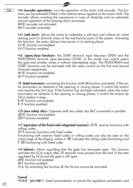
GB •en (encoder operation)= runs the operation of the motor with encoder. This fun-ction can be activated if there is the relative sensor applied on the motor shaft. The encoder allows inverting the manoeuvre in case of obstacles and an extremely precise operation of the slowing down processes.en=0 encoder not activated.en=1 encoder activated.
•ss (soft start)= allows the motor to undertake a soft start and without an initial starting point to diminish stress of the mechanical parts of the system. Activating this function, the motor delivers less power in its starting phase.ss=0 function not enabled.ss=1 function enabled.
•oc (open/close function)= the START terminal input becomes OPEN and the PEDESTRIAN terminal input becomes CLOSE. In this mode one control opens the gate and another closes it without intermediate stops. The PEDESTRIAN and START functions can be activated with the radio control on the fi rst and second channels respectively.oc=0 function not enabled.oc=1 function enabled.
•it (total inversion)= activating this function (with en function activated), if the mo-tor encounters an obstacle in the opening or closing phase, it inverts the motion and reaches the limit stop. If the function has not been activated, when the motor encounters an obstacle in the opening or closing phase, it inverts the motion by 50cm before it stops.it=0 function not enabled.it=1 function enabled.
•2b (two safety ribs)= Operates with two safety ribs 8k2 connected in parallel.2b=0 function not enabled.2b=1 function enabled.
•cf (operation of the fi xed code integrated receiver)= cf=0 receiver functions with rolling codes.cf=1 receiver functions with fi xed codes.Functioning with receiver fi xed codes or rolling codes can also be seen on the initial page of the display, where r-00 indicates the rolling code functioning and f-00 functioning with fi xed code.
•al (alarm)= Alarm signalling that the gate has remained open. This function activates the SCA output after 20 seconds have passed from the end of the time regulated by ttca and the gate is still open.al=0 function not enabled.al=1 function enabled.N.B: By activating the function al, the re one cannot be activated.
Cancel•reset parametri (reset parameters)= to cancel the regulation parameters and
27
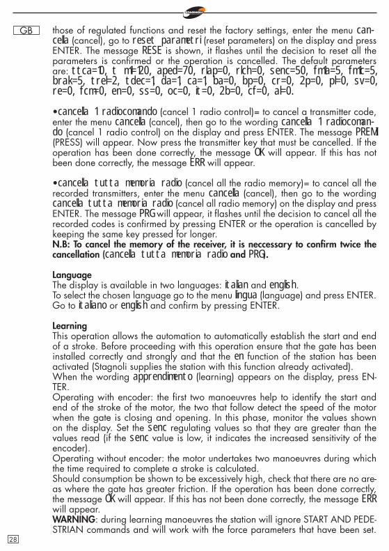
GB those of regulated functions and reset the factory settings, enter the menu can-cella (cancel), go to reset parametri (reset parameters) on the display and press ENTER. The message RESE is shown, it fl ashes until the decision to reset all the parameters is confi rmed or the operation is cancelled. The default parameters are: ttca=10, t m1=120, aped=70, rlap=0, rlch=0, senc=50, fm1a=5, fm1c=5, brak=5, trel=2, tdec=1, da=1, ca=1, ba=0, bp=0, cr=0, 2p=0, pl=0, sv=0, re=0, fcm=0, en=0, ss=0, oc=0, it=0, 2b=0, cf=0, al=0.
•cancella 1 radiocomando (cancel 1 radio control)= to cancel a transmitter code, enter the menu cancella (cancel), then go to the wording cancella 1 radiocoman-do (cancel 1 radio control) on the display and press ENTER. The message PREMI (PRESS) will appear. Now press the transmitter key that must be cancelled. If the operation has been done correctly, the message OK will appear. If this has not been done correctly, the message ERR will appear.
•cancella tutta memoria radio (cancel all the radio memory)= to cancel all the recorded transmitters, enter the menu cancella (cancel), then go to the wording cancella tutta memoria radio (cancel all radio memory) on the display and press ENTER. The message PRG will appear, it fl ashes until the decision to cancel all the recorded codes is confi rmed by pressing ENTER or the operation is cancelled by keeping the same key pressed for longer.N.B: To cancel the memory of the receiver, it is neccessary to confi rm twice the cancellation (cancella tutta memoria radio and PRG).
LanguageThe display is available in two languages: italian and english.To select the chosen language go to the menu lingua (language) and press ENTER. Go to italiano or english and confi rm by pressing ENTER.
LearningThis operation allows the automation to automatically establish the start and end of a stroke. Before proceeding with this operation ensure that the gate has been installed correctly and strongly and that the en function of the station has been activated (Stagnoli supplies the station with this function already activated).When the wording apprendimento (learning) appears on the display, press EN-TER.Operating with encoder: the fi rst two manoeuvres help to identify the start and end of the stroke of the motor, the two that follow detect the speed of the motor when the gate is closing and opening. In this phase, monitor the values shown on the display. Set the senc regulating values so that they are greater than the values read (if the senc value is low, it indicates the increased sensitivity of the encoder).Operating without encoder: the motor undertakes two manoeuvres during which the time required to complete a stroke is calculated.Should consumption be shown to be excessively high, check that there are no are-as where the gate has greater friction. If the operation has been done correctly, the message OK will appear. If this has not been done correctly, the message ERR will appear.WARNING: during learning manoeuvres the station will ignore START AND PEDE-STRIAN commands and will work with the force parameters that have been set.
28
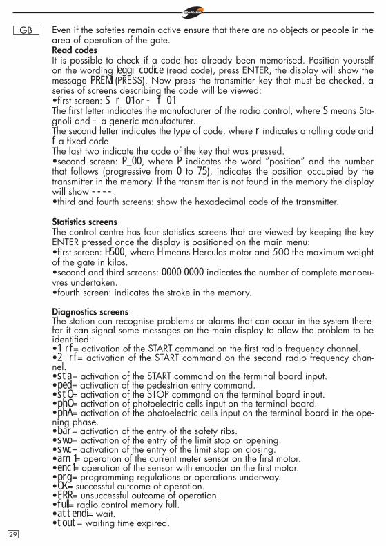
GB Even if the safeties remain active ensure that there are no objects or people in the area of operation of the gate.Read codesIt is possible to check if a code has already been memorised. Position yourself on the wording leggi codice (read code), press ENTER, the display will show the message PREMI (PRESS). Now press the transmitter key that must be checked, a series of screens describing the code will be viewed:•fi rst screen: S r 01 or - f 01.The fi rst letter indicates the manufacturer of the radio control, where S means Sta-gnoli and - a generic manufacturer.The second letter indicates the type of code, where r indicates a rolling code and f a fi xed code.The last two indicate the code of the key that was pressed.•second screen: P_00, where P indicates the word “position” and the number that follows (progressive from 0 to 75), indicates the position occupied by the transmitter in the memory. If the transmitter is not found in the memory the display will show ----.•third and fourth screens: show the hexadecimal code of the transmitter.
Statistics screensThe control centre has four statistics screens that are viewed by keeping the key ENTER pressed once the display is positioned on the main menu:•fi rst screen: H500, where H means Hercules motor and 500 the maximum weight of the gate in kilos.•second and third screens: 0000 0000 indicates the number of complete manoeu-vres undertaken.•fourth screen: indicates the stroke in the memory.
Diagnostics screensThe station can recognise problems or alarms that can occur in the system there-for it can signal some messages on the main display to allow the problem to be identifi ed:•1 rf= activation of the START command on the fi rst radio frequency channel.•2 rf= activation of the START command on the second radio frequency chan-nel.•sta= activation of the START command on the terminal board input.•ped= activation of the pedestrian entry command.•stO= activation of the STOP command on the terminal board input.•phO= activation of photoelectric cells input on the terminal board.•phA= activation of the photoelectric cells input on the terminal board in the ope-ning phase.•bar= activation of the entry of the safety ribs.•swo= activation of the entry of the limit stop on opening.•swc= activation of the entry of the limit stop on closing.•am 1= operation of the current meter sensor on the fi rst motor.•enc1= operation of the sensor with encoder on the fi rst motor.•prg= programming regulations or operations underway.•OK= successful outcome of operation.•ERR= unsuccessful outcome of operation.•full= radio control memory full.•attendi= wait.•tout= waiting time expired.
29
GB
Technical Data•Automation current: 230V - 50/60Hz.•Primary transformer protection fuse: F5A/230V.•24V accessory output protection fuse: T1A.•Integrated receiver (433Mhz): maximum capacity 76 radio codes.•Operating times: -20° +55°•Maximum rated output of the motor: 500W•Maximum power of the fl asher output: 40W•Maximum power of the open gate signal output (SCA): 5W
F.A.Q. - Frequently Asked Questions
Why choose a rolling code transmitter instead of a fi xed one?IRolling code transmitters are safer as they cannot be cloned and have over 200 million combinations that change with each transmission. Fixed code transmitters, instead, have 1024 code combinations that do not change with each transmission.
The station does not recognise the transmitter. Why?Check that you are using the same type of station and transmitter. It is possible to check the type of transmitter used by the station from the main screen and change if necessary by setting the parameter cf.
30

GB
31
Notes
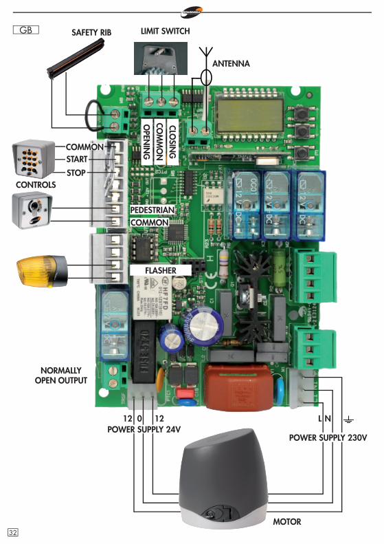
GB SAFETY RIB
CONTROLS
COMMONPEDESTRIAN
FLASHER
012 12 L N
LIMIT SWITCH
MOTOR
COMMON
STOP
START
CLOSIN
GCO
MM
ON
OPEN
ING
ANTENNA
POWER SUPPLY 24VPOWER SUPPLY 230V
NORMALLY OPEN OUTPUT
32

GB
ENCO
DER
MO
TOR
FLASHER
CONDENSATOR
CLOSINGCOMMONOPENING
PHO
TOCE
LLS
IN O
PEN
ING
PHO
TOCE
LLS
IN C
LOSI
NG
TXRX
RXTX
PHOTOCELLS POWER SUPPLY
COMMON
PHOTOCELLS IN CLOSINGPHOTOCELLS IN OPENING AND IN CLOSING
33
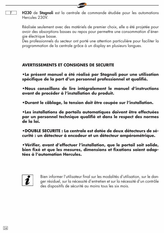
F H230 de Stagnoli est la centrale de commande étudiée pour les automations Hercules 230V.
Réalisée seulement avec des matériels de premier choix, elle a été projetée pour avoir des absorptions basses au repos pour permettre une consommation d’éner-gie électrique basse. Des professionnels du secteur ont porté une attention particulière pour faciliter la programmation de la centrale grâce à un display en plusieurs langues.
AVERTISSEMENTS ET CONSIGNES DE SECURITE
•Le présent manuel a été réalisé par Stagnoli pour une utilisation spécifi que de la part d’un personnel professionnel et qualifi é.
•Nous conseillons de lire intégralement le manuel d’instructions avant de procéder à l’installation du produit.
•Durant le câblage, la tension doit être coupée sur l’installation.
•Les installations de portails automatiques doivent être effectuées par un personnel technique qualifi é et dans le respect des normes de la loi.
•DOUBLE SECURITE : La centrale est dotée de deux détecteurs de sé-curité : un détecteur à encodeur et un détecteur ampérométrique.
•Vérifi er, avant d’effectuer l’installation, que le portail soit solide, bien fi xé et que les mesures, dimensions et fi xations soient adap-tées à l’automation Hercules.
Bien informer l’utilisateur fi nal sur les modalités d’utilisation, sur le dan-ger résiduel, sur la nécessité d’entretien et sur la nécessité d’un contrôle des dispositifs de sécurité au moins tous les six mois.
34
F
789
101112131415161718
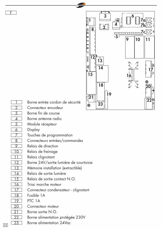
Touches de programmationConnecteurs entrées/commandesRelais de directionRelais de freinageRelais clignotantBorne 24V/sortie lumière de courtoisieMémoire installation (extractible)Relais de sortie lumièreRelais de sortie contact N.O.Triac marche moteurConnecteur condensateur - clignotantFusible 1A
19 PTC 1A20 Connecteur moteur21 Borne sortie N.O.22 Borne alimentation protégée 230V
654321
DisplayModule récepteurBorne antenne radioBorne fi n de courseConnecteur encodeurBorne entrée cordon de sécurité
1
20
19
18
171615
14
1312
11109
8
7a6
5
4
3
2 7b7c
2322
21
23 Borne alimentation 24Vac35
F
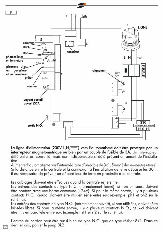
La ligne d’alimentation (230V L,N, ) vers l’automatisme doit être protégée par un interrupteur magnétométrique ou bien par un couple de fusible de 5A. Un interrupteur différentiel est conseillé, mais non indispensable si déjà présent en amont de l’installa-tion. Alimenter l’automatisme par l’intermédiaire d’un câble de 3x1,5mm2 (phase+neutre+terre). Si la distance entre la centrale et la connexion à l’installation de terre dépasse les 30m, il est nécessaire de prévoir un déperditeur de terre en proximité à la centrale.
Les câblages doivent être effectués quand la centrale est éteinte. Les entrées des contacts de type N.C. (normalement fermé), si non utilisées, doivent être pontées avec une borne commune (+24V). Si pour la même entrée, il y a plusieurs contacts N.C., ceux-ci doivent être mis en série entre eux (exemple: ph1 et ph2 sur le schéma).Les entrées des contacts de type N.O. (normalement ouvert), si non utilisées, doivent être laissées libres. Si pour la même entrée, il y a plusieurs contacts N.O., ceux-ci doivent être mis en parallèle entre eux (exemple : st1 et st2 sur le schéma).
L’entrée du cordon peut être aussi bien de type N.C. que de type résistif 8k2. Dans ce dernier cas, ponter le jump 8k2.
L N
voyant portail ouvert (SCA)
sortie N.O.
LIGNE
st1
st3
5w
24Vac
+12V
+12V
230V40W
ph1
ph3
st2
ph2
communstart
stopphotocellules en fermeture
photocellules en ouverture et en fermeture
piéton
commun
clignotant
230
12 0 12TRANSFORMATEUR
FUSIBLE
encodeur
36
F
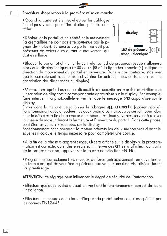
•Quand la carte est éteinte, effectuer les câblages électriques voulus pour l’installation puis les con-trôler
•Débloquer le portail et en contrôler le mouvement (la crémaillère ne doit pas être soutenue par le pi-gnon du moteur). La course du portail ne doit pas présenter de points durs durant le mouvement qui doit être fl uide.
E
•Bloquer le portail et alimenter la centrale. La led de présence réseau s’allumera alors et le display indiquera r|-00 ou r-|00 où la ligne horizontale (-) indique la direction du mouvement du portail en ouverture. Dans le cas contraire, s’assurer que la centrale soit sous tension et vérifi er les entrées mises en fonction (voir la description des diagnostics du display).
•Mettre, l’un après l’autre, les dispositifs de sécurité en marche et vérifi er que l’inscription de diagnostic correspondante apparaisse sur le display. Par exemple, faire intervenir la photocellule et vérifi er que le message pho apparaisse sur le display. Entrer dans le menu et sélectionner la rubrique apprendimento (apprentissage). Fonctionnement avec encodeur: les deux premières manœuvres servent pour iden-tifi er le début et la fi n de la course du moteur. Les deux suivantes servent à relever la vitesse du moteur durant la fermeture et l’ouverture du portail. Dans cette phase, contrôler les valeurs visualisées sur le display. Fonctionnement sans encoder: le moteur effectue les deux manœuvres durant le-squelles il calcule le temps nécessaire pour compléter une course.
•A la fi n de la phase d’apprentissage, ok sera affi ché sur le display si la program-mation est correcte, ou si des erreurs sont intervenues err sera affi ché. Pour sortir de la programmation, appuyer sur la touche de sélection ENTER.
•Programmer correctement les niveaux de force anti-écrasement en ouverture et en fermeture, qui doivent être supérieurs aux valeurs maxima visualisées durant l’apprentissage.
ATTENTION: ce réglage peut infl uencer le degré de sécurité de l’automation.
•Effectuer quelques cycles d’essai en vérifi ant le fonctionnement correct de toute l’installation.
•Effectuer les mesures de la force d’impact du portail selon ce qui est spécifi é par les normes EN12445.
display
LED de présence réseau électrique
Procédure d’opération à la première mise en marche
37
F
r|-00
agg. radioc.
1ch
regolazioni
ttca
funzioni
ca
ba
fm1a
fm1c
bp
cr
2p
pl
re
ss
it
cfal
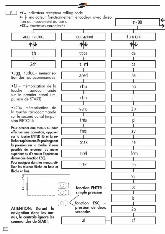
•agg. radioc.= mémorisa-tion des radiocommandes
•1ch= mémorisation de la touche radiocommande sur le premier canal (im-pulsion de START)
•2ch= mémorisation de la touche radiocommande sur le second canal (impul-sion PIETON)
Pour accéder aux menus ou pour effectuer une opération, appuyer sur la touche ENTER (E) et la re-lâcher rapidement. En prolongeant la pression sur la touche, il sera possible de retourner au menu supérieur ou d’annuler l’opération demandée (fonction ESC).Pour naviguer dans les menus, uti-liser les touches fl èche en haut et fl èche en bas.
E
•r= indicateur récepteur rolling code•-|= indicateur fonctionnement encodeur avec direc-tion du mouvement du portail•00= émetteurs enregistrés
ATTENTION: Durant la navigation dans les me-nus, la centrale ignore les commandes de START.
t m1
da
fcm
2b
2ch
fonction ENTER – simple pression
fonction ESC – pression de deux secondes
sv
en
oc
aped
senc
brak
trel
tdec
rlap
rlch
38
F
00
cancella
reset parametri
cancella 1 radiocomando
lingua
italiano
english
apprendimento
leggi codice
cancella tutta memoria radio
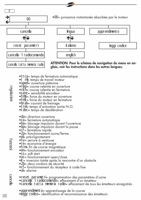
•ttca= temps de fermeture automatique•t m1= temps de travail moteur•aped= ouverture piétonne•rlap= course ralentie en ouverture•rlch= course ralentie en fermeture•senc= sensibilité encodeur•fm1a= force du moteur en ouverture•fm1c= force du moteur en fermeture•brak= courant de freinage•trel= temps d’activation sortie N.O.•tdec= temps de décélération
•da= direction ouverture•ca= fermeture automatique•ba= blocage impulsion durant l’ouverture•bp= blocage impulsion durant la pause•cr= fermeture rapide•2p= fonctionnement ouvre/ferme•pl= pré-clignotement•sv= serrure à ventouse•re= économie d’énergie•fcm= fi n de course magnétique•en= fonctionnement encodeur•ss= soft start•oc= fonctionnement open/close•it= inversion totale après la rencontre d’un obstacle•2b= deux cordons de sécurité•cf= fonctionnement du récepteur à code fi xe•al= alarme
•reset parametri= programmation des paramètres d’usine•cancella 1 radiocomando= effacement d’un émetteur•cancella tutta memoria radio= effacement de tous les émetteurs enregistrés
•apprendimento= apprentissage de la course•leggi codice= identifi cation et reconnaissance des émetteurs
regolazionifunzioni
•00= puissance instantanée absorbée par le moteur
cancella
ATTENTION: Pour le schéma de navigation du menu en an-glais, voir les instructions dans les autres langues.
39
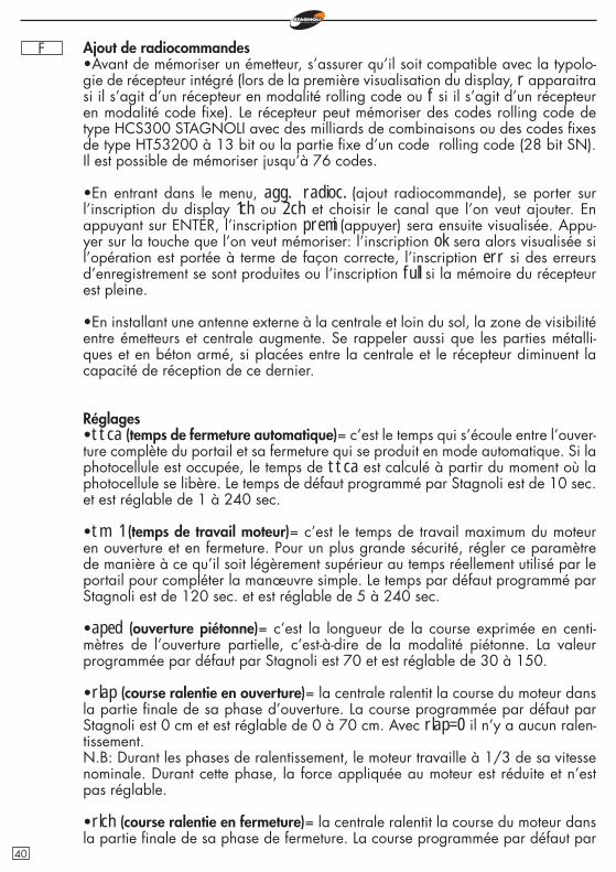
F Ajout de radiocommandes•Avant de mémoriser un émetteur, s’assurer qu’il soit compatible avec la typolo-gie de récepteur intégré (lors de la première visualisation du display, r apparaitra si il s’agit d’un récepteur en modalité rolling code ou f si il s’agit d’un récepteur en modalité code fi xe). Le récepteur peut mémoriser des codes rolling code de type HCS300 STAGNOLI avec des milliards de combinaisons ou des codes fi xes de type HT53200 à 13 bit ou la partie fi xe d’un code rolling code (28 bit SN). Il est possible de mémoriser jusqu’à 76 codes.
•En entrant dans le menu, agg. radioc. (ajout radiocommande), se porter sur l’inscription du display 1ch ou 2ch et choisir le canal que l’on veut ajouter. En appuyant sur ENTER, l’inscription premi (appuyer) sera ensuite visualisée. Appu-yer sur la touche que l’on veut mémoriser: l’inscription ok sera alors visualisée si l’opération est portée à terme de façon correcte, l’inscription err si des erreurs d’enregistrement se sont produites ou l’inscription full si la mémoire du récepteur est pleine.
•En installant une antenne externe à la centrale et loin du sol, la zone de visibilité entre émetteurs et centrale augmente. Se rappeler aussi que les parties métalli-ques et en béton armé, si placées entre la centrale et le récepteur diminuent la capacité de réception de ce dernier.
Réglages•ttca (temps de fermeture automatique)= c’est le temps qui s’écoule entre l’ouver-ture complète du portail et sa fermeture qui se produit en mode automatique. Si la photocellule est occupée, le temps de ttca est calculé à partir du moment où la photocellule se libère. Le temps de défaut programmé par Stagnoli est de 10 sec. et est réglable de 1 à 240 sec.
•tm 1 (temps de travail moteur)= c’est le temps de travail maximum du moteur en ouverture et en fermeture. Pour un plus grande sécurité, régler ce paramètre de manière à ce qu’il soit légèrement supérieur au temps réellement utilisé par le portail pour compléter la manœuvre simple. Le temps par défaut programmé par Stagnoli est de 120 sec. et est réglable de 5 à 240 sec.
•aped (ouverture piétonne)= c’est la longueur de la course exprimée en centi-mètres de l’ouverture partielle, c’est-à-dire de la modalité piétonne. La valeur programmée par défaut par Stagnoli est 70 et est réglable de 30 à 150.
•rlap (course ralentie en ouverture)= la centrale ralentit la course du moteur dans la partie fi nale de sa phase d’ouverture. La course programmée par défaut par Stagnoli est 0 cm et est réglable de 0 à 70 cm. Avec rlap=0 il n’y a aucun ralen-tissement.N.B: Durant les phases de ralentissement, le moteur travaille à 1/3 de sa vitesse nominale. Durant cette phase, la force appliquée au moteur est réduite et n’est pas réglable.
•rlch (course ralentie en fermeture)= la centrale ralentit la course du moteur dans la partie fi nale de sa phase de fermeture. La course programmée par défaut par
40
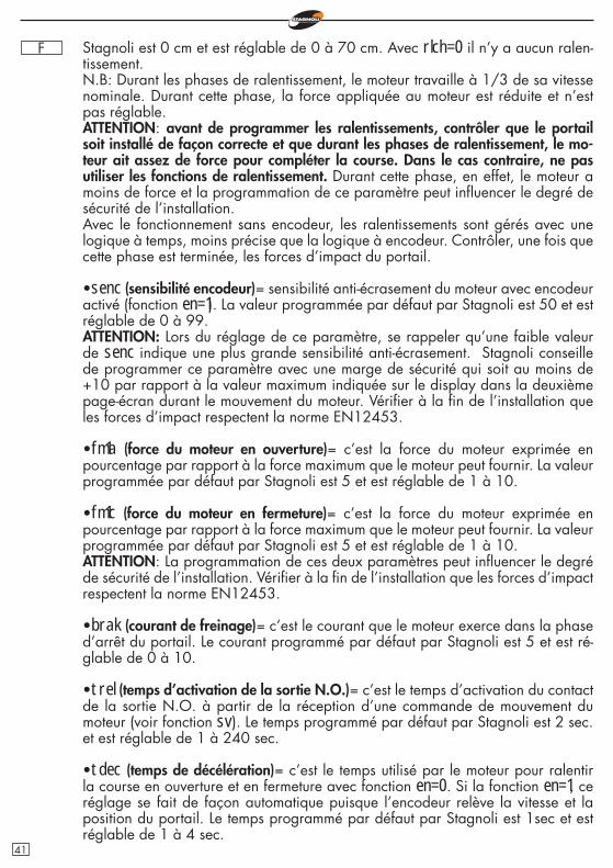
F Stagnoli est 0 cm et est réglable de 0 à 70 cm. Avec rlch=0 il n’y a aucun ralen-tissement.N.B: Durant les phases de ralentissement, le moteur travaille à 1/3 de sa vitesse nominale. Durant cette phase, la force appliquée au moteur est réduite et n’est pas réglable.ATTENTION: avant de programmer les ralentissements, contrôler que le portail soit installé de façon correcte et que durant les phases de ralentissement, le mo-teur ait assez de force pour compléter la course. Dans le cas contraire, ne pas utiliser les fonctions de ralentissement. Durant cette phase, en effet, le moteur a moins de force et la programmation de ce paramètre peut infl uencer le degré de sécurité de l’installation. Avec le fonctionnement sans encodeur, les ralentissements sont gérés avec une logique à temps, moins précise que la logique à encodeur. Contrôler, une fois que cette phase est terminée, les forces d’impact du portail.
•senc (sensibilité encodeur)= sensibilité anti-écrasement du moteur avec encodeur activé (fonction en=1). La valeur programmée par défaut par Stagnoli est 50 et est réglable de 0 à 99.ATTENTION: Lors du réglage de ce paramètre, se rappeler qu’une faible valeur de senc indique une plus grande sensibilité anti-écrasement. Stagnoli conseille de programmer ce paramètre avec une marge de sécurité qui soit au moins de +10 par rapport à la valeur maximum indiquée sur le display dans la deuxième page-écran durant le mouvement du moteur. Vérifi er à la fi n de l’installation que les forces d’impact respectent la norme EN12453.
•fm1a (force du moteur en ouverture)= c’est la force du moteur exprimée en pourcentage par rapport à la force maximum que le moteur peut fournir. La valeur programmée par défaut par Stagnoli est 5 et est réglable de 1 à 10.
•fm1c (force du moteur en fermeture)= c’est la force du moteur exprimée en pourcentage par rapport à la force maximum que le moteur peut fournir. La valeur programmée par défaut par Stagnoli est 5 et est réglable de 1 à 10.ATTENTION: La programmation de ces deux paramètres peut infl uencer le degré de sécurité de l’installation. Vérifi er à la fi n de l’installation que les forces d’impact respectent la norme EN12453.
•brak (courant de freinage)= c’est le courant que le moteur exerce dans la phase d’arrêt du portail. Le courant programmé par défaut par Stagnoli est 5 et est ré-glable de 0 à 10.
•trel (temps d’activation de la sortie N.O.)= c’est le temps d’activation du contact de la sortie N.O. à partir de la réception d’une commande de mouvement du moteur (voir fonction sv). Le temps programmé par défaut par Stagnoli est 2 sec. et est réglable de 1 à 240 sec.
•tdec (temps de décélération)= c’est le temps utilisé par le moteur pour ralentir la course en ouverture et en fermeture avec fonction en=0. Si la fonction en=1, ce réglage se fait de façon automatique puisque l’encodeur relève la vitesse et la position du portail. Le temps programmé par défaut par Stagnoli est 1sec et est réglable de 1 à 4 sec.
41
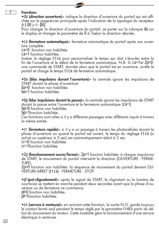
F Fonctions•da (direction ouverture)= indique la direction d’ouverture du portail qui est affi -chée sur la page-écran principale après l’indication de la typologie du récepteur (r|-00 o r-|00).Pour changer la direction d’ouverture du portail, se porter sur la rubrique da sur le display et changer le paramètre de 0 à 1 selon la direction désirée.
•ca (fermeture automatique)= fermeture automatique du portail après son ouver-ture complète.ca=0 fonction non habilitée.ca=1 fonction habilitée.Insérer le réglage ttca pour personnaliser le temps qui doit s’écouler entre la fi n de l’ouverture et le début de la fermeture automatique. N.B: Si ca=1 et 2p=0, une commande de START, donnée alors que le portail est en ouverture, arrête le portail et charge le temps ttca de fermeture automatique.
•ba (bloc impulsions durant l’ouverture)= la centrale ignore les impulsions de START durant la phase d’ouverture.ba=0 fonction non habilitée.ba=1 fonction habilitée.
•bp (bloc impulsions durant la pause)= la centrale ignore les impulsions de START durant la pause entre l’ouverture et la fermeture automatique (ca=1).bp=0 fonction non habilitée.bp=1 fonction habilitée.Ces fonctions sont utiles si il y a différents passages avec différents inputs à travers la même entrée.
•cr (fermeture rapide)= si il y a un passage à travers les photocellules durant la phase d’ouverture ou quand le portail est ouvert, le temps du réglage ttca (si activé ou supérieur à 3 sec) est automatiquement réduit à 3 sec.cr=0 fonction non habilitée.cr=1 fonction habilitée.
•2p (fonctionnement ouvre/ferme)= 2p=1 fonction habilitée: à chaque impulsions de START, le mouvement du portail intervertit la direction (OUVERTURE - FERME-TURE).2p=0 fonction non habilitée: la séquence de mouvement du portail devient OU-VERTURE-ARRET (ttca) - FERMETURE - STOP.
•pl (pré-clignotement)= après le signal de START, le clignotant ou la lumière de courtoisie se mettent en marche pendant deux secondes avant que la phase d’ou-verture ou de fermeture ne commence. pl=0 fonction non habilitée.pl=1 fonction habilitée.
•sv (serrure à ventouse)= en activant cette fonction, la sortie N.O. garde toujours le contact fermé sauf pendant le temps réglé par le paramètre treI à partir du dé-but du mouvement du moteur. Cette modalité gère le fonctionnement d’une serrure électrique à ventouse.
42
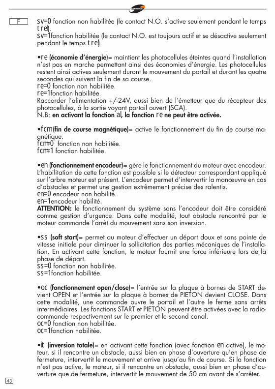
F sv=0 fonction non habilitée (le contact N.O. s’active seulement pendant le temps trel).sv=1 fonction habilitée (le contact N.O. est toujours actif et se désactive seulement pendant le temps trel).
•re (économie d’énergie)= maintient les photocellules éteintes quand l’installation n’est pas en marche permettant ainsi des économies d’énergie. Les photocellules restent ainsi actives seulement durant le mouvement du portail et durant les quatre secondes qui suivent la fi n de sa course. re=0 fonction non habilitée.re=1 fonction habilitée.Raccorder l’alimentation +/-24V, aussi bien de l’émetteur que du récepteur des photocellules, à la sortie voyant portail ouvert (SCA). N.B: en activant la fonction al, la fonction re ne peut être activée.
•fcm (fi n de course magnétique)= active le fonctionnement du fi n de course ma-gnétique.fcm=0 fonction non habilitée.fcm=1 fonction habilitée.
•en (fonctionnement encodeur)= gère le fonctionnement du moteur avec encodeur. L’habilitation de cette fonction est possible si le détecteur correspondant appliqué sur l’arbre moteur est présent. L’encodeur permet d’intervertir la manœuvre en cas d’obstacles et permet une gestion extrêmement précise des ralentis. en=0 encodeur non habilité.en=1 encodeur habilité.ATTENTION: le fonctionnement du système sans l’encodeur doit être considéré comme gestion d’urgence. Dans cette modalité, tout obstacle rencontré par le moteur commande l’arrêt du mouvement sans son inversion.
•ss (soft start)= permet au moteur d’effectuer un départ doux et sans pointe de vitesse initiale pour diminuer la sollicitation des parties mécaniques de l’installa-tion. En activant cette fonction, le moteur fournit une force inférieure lors de la phase de départ. ss=0 fonction non habilitée.ss=1 fonction habilitée.
•oc (fonctionnement open/close)= l’entrée sur la plaque à bornes de START de-vient OPEN et l’entrée sur la plaque à bornes de PIETON devient CLOSE. Dans cette modalité, une commande ouvre le portail et l’autre le ferme sans arrêts intermédiaires. Les fonctions START et PIETON peuvent être activées avec la radio-commande respectivement sur le premier et le second canal. oc=0 fonction non habilitée.oc=1 fonction habilitée.
•it (inversion totale)= en activant cette fonction (avec fonction en active), le mo-teur, si il rencontre un obstacle, aussi bien en phase d’ouverture qu’en phase de fermeture, intervertit le mouvement et arrive jusqu’au fi n de course. Si la fonction n’est pas active, le moteur, si il rencontre un obstacle, aussi bien en phase d’ou-verture que de fermeture, intervertit le mouvement de 50 cm avant de s’arrêter.
43
F it=0 fonction non habilitée.it=1 fonction habilitée.
•2b (deux cordons de sécurité)= Fonctionnement avec deux cordons de sécurité 8k2 reliés en parallèle.2b=0 fonction non habilitée.2b=1 fonction habilitée.
•cf (fonctionnement du récepteur intégré à code fi xe)= cf=0 récepteur fonction-nant avec les codes rolling code.cf=1 récepteur fonctionnant avec les codes fi xes.Le fonctionnement à code fi xe ou à rolling code du récepteur est affi ché aussi sur la page-écran initiale du display, où r-00 indique le fonctionnement à rolling code et f-00 à code fi xe.
•al (alarme)= Alarme qui signale que le portail est resté ouvert. Cette fonction active la sortie SCA, 20 secondes après la fi n du temps réglé par ttca quand le portail résulte encore ouvert.al=0 fonction non habilitée.al=1 fonction habilitéeN.B: en activant la fonction al, la fonction re ne peut être activée.
Effacer•reset parametri (reset paramètres)= pour effacer les paramètres des réglages et des fonctions réglés et reprogrammer les paramètres d’usine, une fois entré dans le menu cancella (effacer), se porter sur l’inscription reset parametri sur le display et appuyer sur la touche ENTER. Le message RESE sera affi ché et clignote-ra tant que l’intention de reprogrammer tous les paramètres ou d’annuler l’opéra-tion ne sera pas confi rmée. Les paramètres insérés par défaut sont: ttca=10, t m1=120, aped=70, rlap=0, rlch=0, senc=50, fm1a=5, fm1c=5, brak=5, trel=2, tdec=1, da=1, ca=1, ba=0, bp=0, cr=0, 2p=0, pl=0, sv=0, re=0, fcm=0, en=0, ss=0, oc=0, it=0, 2b=0, cf=0, al=0.
•cancella 1 radiocomando (efface 1 radiocommande)= pour effacer le code d’un émetteur, une fois entré dans le menu cancella (effacer), se porter sur l’inscription cancella 1 radiocomando sur le display et appuyer sur la touche ENTER. Le mes-sage PREMI sera affi ché. Appuyer alors sur la touche de l’émetteur à effacer. Si l’opération est correctement menée à terme, le message OK sera affi ché. Dans le cas contraire, ERR sera affi ché.
•cancella tutta memoria radio (efface toute la mémoire radio)= pour effacer tous les émetteurs enregistrés, une fois entré dans le menu cancella (effacer), se porter sur l’inscription cancella tutta memoria radio sur le display et appuyer sur la touche ENTER. Le message PRG sera affi ché et clignotera tant que l’intention d’effacer tous les codes enregistrés en appuyant sur la touche ENTER ou d’annuler l’opération en prolongeant la pression de la touche, ne sera pas confi rmée.N.B: Pour porter l’effacement de la mémoire radio à terme, il est demandé de confi rmer deux fois la volonté d’effacer (cancella tutta memoria radio et PRG).
44
F LangueLes messages sur le display peuvent être affi chés en deux langues: italiano et english.Pour choisir la langue de fonctionnement, se porter sur le menu lingua (langue) et appuyer sur ENTER. Se porter alors sur la langue italiano ou english et confi rmer en appuyant de nouveau sur ENTER.
ApprentissageCette opération permet à l’automation d’établir automatiquement le début et la fi n de la course. Avant de procéder à cette opération, s’assurer que le portail soit solidement installé et que la fonction en de la centrale soit active (Stagnoli fournit la centrale avec cette fonction déjà active).Une fois que la rubrique apprendimento (apprentissage) est visualisée sur le di-splay, appuyer sur la touche ENTER. Fonctionnement avec encodeur: les deux premières manœuvres servent à identi-fi er le début et la fi n de la course du moteur. Les deux suivantes servent à relever la vitesse du moteur durant la fermeture et l’ouverture du portail. Dans cette phase, contrôler les valeurs affi chées à l’écran. Programmer ensuite les valeurs du régla-ge senc de façon à ce qu’elles soient supérieures aux valeurs relevées (si la valeur de senc est basse, elle indique une plus grande sensibilité de l’encodeur).Fonctionnement sans encodeur: le moteur exécute deux manœuvres durant le-squelles il calcule le temps nécessaire pour compléter une course. Si la consommation est particulièrement élevée, vérifi er qu’il n’y ait pas de points où le portail rencontre des frictions plus importantes. Si l’opération est portée à terme de façon correcte, le message OK sera affi ché, dans le cas contraire le message ERR sera affi ché. ATTENTION: durant les manœuvres d’apprentissage, la centrale ignore les com-mandes de START et de PIETON et travaille avec les paramètres de force pro-grammés. Même si les sécurités restent actives, s’assurer qu’il n’y ait pas d’objets ou de personnes sur la trajectoire de travail du portail.
Lire le codeIl est possible de vérifi er si un code a déjà été mémorisé. Se positionner sur l’in-scription leggi codice (lire le code) et appuyer sur la touche ENTER, pour que le message PREMI (appuyer) soit affi ché sur le display. En appuyant alors sur la tou-che de l’émetteur que l’on désire vérifi er, une série de pages-écrans de description du code sera visualisée: •première page-écran: S r 01 ou - f 01.Le premier caractère indique le producteur de la radiocommande, où S indique Stagnoli et - un producteur générique. Le deuxième caractère indique la typologie de code où r indique rolling code et f code fi xe.Les deux derniers caractères indiquent le code de la touche enfoncée.•deuxième page-écran: P_00, où P indique le mot “position” et le nombre suivant (progressif de 0 à 75), indique, la position occupée par l’émetteur en mémoire. Si l’émetteur n’est pas présent en mémoire, ---- s’affi chera sur le display. •troisième et quatrième pages-écrans: la codifi cation hexadécimale de l’émetteur sera affi chée.
45
F Pages-écrans de statistiqueLa centrale de commande dispose de quatre pages-écrans de statistique qui sont affi chées en maintenant la pression sur la touche ENTER une fois que le display est positionné sur le menu principal:•première page-vidéo: H500, où H indique le moteur Hercules et 500 le poids du portail en kilos qu’il peut porter•deuxième et troisième pages-écrans: 0000 0000 indiquent le nombre de manœu-vres complètes effectuées. •quatrième page-écran: indique la course en mémoire.
Pages-écrans de diagnosticLa centrale est en mesure de reconnaitre les problèmes ou les alarmes qui peuvent se produire sur l’installation et pour lesquels elle peut signaler certains messages sur le display pour permettre de déterminer le problème:•1 rf= activation de la commande de START sur le premier canal de radiofréquen-ce.•2 rf= activation de la commande de START sur le second canal de radiofréquen-ce.•sta= activation de la commande de START sur l’entrée de la plaque à bornes.•ped= activation de la commande d’entrée piétonne.•stO= activation de la commande de STOP sur l’entrée de la plaque à bornes.•phO= activation de l’entrée des photocellules sur la plaque à bornes.•phA= activation de l’entrée des photocellules sur la plaque à bornes en phase d’ouverture.•bar= activation de l’entrée du cordon de sécurité.•swo= activation de l’entrée du fi n de course en ouverture.•swc= activation de l’entrée du fi n de course en fermeture.•am 1= intervention du détecteur ampérométrique sur le premier moteur.•enc1= intervention du détecteur à encodeur sur le premier moteur.•prg= programmation des réglages ou des fonctions en cours.•OK= résultat positif de l’opération.•ERR= résultat négatif de l’opération.•full= mémoire radiocommandes pleine.•attendi= pause d’attente.•tout= temps d’attente écoulé.
46
F
Données Techniques•Alimentation de l’automation: 230V - 50/60Hz.•Fusible de protection primaire transformateur: F5A/230V.•Fusible de protection de la sortie accessoires 24V: T1A.•Récepteur intégré (433Mhz): capacité maximum 76 codes radio.•Température de fonctionnement: -20° +55°•Puissance nominale maximum du moteur: 500W•Puissance maximum de la sortie du clignotant: 40W•Puissance maximum de la sortie du voyant portail ouvert (SCA): 5W
F.A.Q. – Les questions les plus fréquemment posées
Pourquoi choisir un émetteur rolling code plutôt qu’un émetteur à code fi xe?Les émetteurs rolling code sont considérés plus sûrs car ils ne peuvent pas être clonés et ont plus de 200 millions de combinaisons qui changent à chaque transmission. Les émetteurs à code fi xe, en revanche, disposent de 1024 combinaisons de codes qui ne changent pas à chaque transmission.
La centrale ne reconnait pas l’émetteur. Pourquoi?S’assurer d’utiliser une centrale et des émetteurs du même type. Dans la première page-vidéo principale, il est possible de vérifi er le type de récepteur utilisé par la centrale et éventuellement de le changer en programmant le paramètre cf.
47
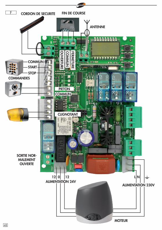
F CORDON DE SECURITE
COMMANDES
COMMUNPIETON
CLIGNOTANT
012 12 L N
FIN DE COURSE
MOTEUR
COMMUN
STOP
START
FERMETU
RECO
MM
UN
OU
VERTU
RE
ANTENNE
ALIMENTATION 24VALIMENTATION 230V
SORTIE NOR-MALEMENT OUVERTE
48
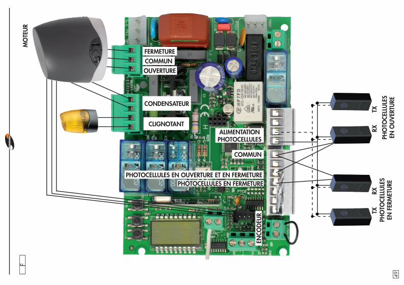
F
ENCO
DEU
R
MO
TEU
R
CLIGNOTANT
CONDENSATEUR
FERMETURECOMMUNOUVERTURE
PHO
TOCE
LLU
LES
EN F
ERM
ETU
REPH
OTO
CELL
ULE
S EN
OU
VER
TURE
TXRX
RXTX
ALIMENTATION PHOTOCELLULES
COMMUN
PHOTOCELLULES EN FERMETUREPHOTOCELLULES EN OUVERTURE ET EN FERMETURE
49
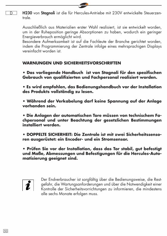
D H230 von Stagnoli ist die für Hercules-Antriebe mit 230V entwickelte Steuerzen-trale.
Ausschließlich aus Materialien erster Wahl realisiert, ist sie entwickelt worden, um in der Ruheposition geringe Absorptionen zu haben, wodurch ein geringer Energieverbrauch ermöglicht wird.Besondere Aufmerksamkeit ist auf die Fachleute der Branche gerichtet worden, indem die Programmierung der Zentrale infolge eines mehrsprachigen Displays vereinfacht worden ist.
WARNUNGEN UND SICHERHEITSVORSCHRIFTEN
• Das vorliegende Handbuch ist von Stagnoli für den spezifi schen Gebrauch von qualifi zierten und Fachpersonal realisiert worden.
• Es wird empfohlen, das Bedienungshandbuch vor der Installation des Produkts vollständig zu lesen.
• Während der Verkabelung darf keine Spannung auf der Anlage vorhanden sein.
• Die Anlagen der automatischen Tore müssen von technischem Fa-chpersonal und unter Beachtung der gesetzlichen Bestimmungen installiert werden.
• DOPPELTE SICHERHEIT: Die Zentrale ist mit zwei Sicherheitssenso-ren ausgerüstet: ein Encoder- und ein Stromsensor.
• Prüfen Sie vor der Installation, dass das Tor stabil, gut befestigt und Maße, Abmessungen und Befestigungen für die Hercules-Auto-matisierung geeignet sind.
Der Endverbraucher ist sorgfältig über die Bedienungsweise, die Rest-gefahr, die Wartungsanforderungen und über die Notwendigkeit einer Kontrolle der Sicherheitsvorrichtungen zu informieren, die mindestens alle sechs Monate erfolgen muss.
50
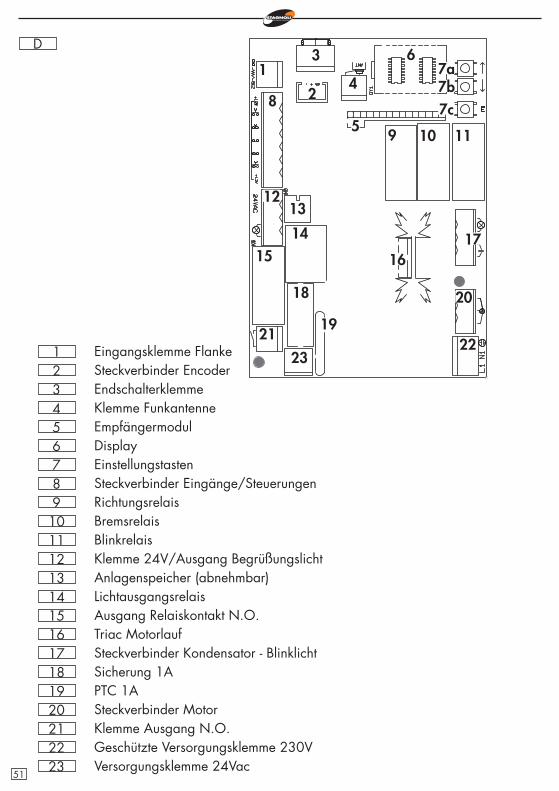
D
789
101112131415161718
EinstellungstastenSteckverbinder Eingänge/SteuerungenRichtungsrelaisBremsrelaisBlinkrelaisKlemme 24V/Ausgang BegrüßungslichtAnlagenspeicher (abnehmbar)LichtausgangsrelaisAusgang Relaiskontakt N.O.Triac MotorlaufSteckverbinder Kondensator - BlinklichtSicherung 1A
19 PTC 1A20 Steckverbinder Motor21 Klemme Ausgang N.O.22 Geschützte Versorgungsklemme 230V
654321
DisplayEmpfängermodulKlemme FunkantenneEndschalterklemmeSteckverbinder EncoderEingangsklemme Flanke
1
20
19
18
171615
14
1312
11109
8
7a6
5
4
3
2 7b7c
2322
21
23 Versorgungsklemme 24Vac51
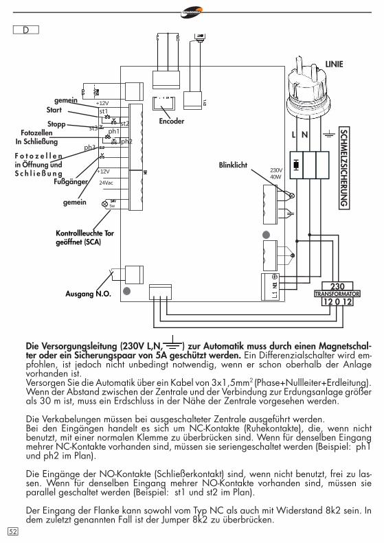
D
Die Versorgungsleitung (230V L,N, ) zur Automatik muss durch einen Magnetschal-ter oder ein Sicherungspaar von 5A geschützt werden. Ein Differenzialschalter wird em-pfohlen, ist jedoch nicht unbedingt notwendig, wenn er schon oberhalb der Anlage vorhanden ist.Versorgen Sie die Automatik über ein Kabel von 3x1,5mm2
(Phase+Nullleiter+Erdleitung). Wenn der Abstand zwischen der Zentrale und der Verbindung zur Erdungsanlage größer als 30 m ist, muss ein Erdschluss in der Nähe der Zentrale vorgesehen werden.
Die Verkabelungen müssen bei ausgeschalteter Zentrale ausgeführt werden.Bei den Eingängen handelt es sich um NC-Kontakte (Ruhekontakte), die, wenn nicht benutzt, mit einer normalen Klemme zu überbrücken sind. Wenn für denselben Eingang mehrer NC-Kontakte vorhanden sind, müssen sie seriengeschaltet werden (Beispiel: ph1 und ph2 im Plan).
Die Eingänge der NO-Kontakte (Schließerkontakt) sind, wenn nicht benutzt, frei zu las-sen. Wenn für denselben Eingang mehrer NO-Kontakte vorhanden sind, müssen sie parallel geschaltet werden (Beispiel: st1 und st2 im Plan).
Der Eingang der Flanke kann sowohl vom Typ NC als auch mit Widerstand 8k2 sein. In dem zuletzt genannten Fall ist der Jumper 8k2 zu überbrücken.
L N
Kontrollleuchte Tor geöffnet (SCA)
Ausgang N.O.
LINIE
st1
st3
5w
24Vac
+12V
+12V
230V40W
ph1
ph3
st2
ph2
gemeinStart
StoppFotozellen
In Schließung
F o t o z e l l e nin Öffnung und S c h l i e ß u n g
Fußgänger
gemein
Blinklicht
230
12 0 12TRANSFORMATOR
SCHM
ELZSICHERU
NG
Encoder
52
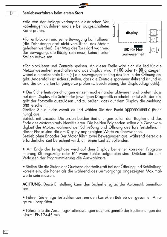
D Betriebsverfahren beim ersten Start
•die von der Anlage verlangten elektrischen Ver-kabelungen ausführen und sie bei ausgeschalteter Karte prüfen.
•Tor entblocken und seine Bewegung kontrollieren (die Zahnstange darf nicht vom Ritzel des Motors gehalten werden). Der Weg des Tors darf während der Bewegung, die fl üssig sein muss, keine harten Stellen aufweisen.
E
•Tor blockieren und Zentrale speisen. An dieser Stelle wird sich die Led für die Netzanwesenheit einschalten und das Display wird r|-00 oder r-|00 anzeigen, wobei die horizontale Linie (-) die Bewegungsrichtung des Tors in der Öffnung an-gibt. Andernfalls ist sicherzustellen, dass die Zentrale spannungsführend ist und es sind die aktivierten Eingänge zu prüfen (s. Beschreibung der Displaydiagnostik).
• Die Sicherheitsvorrichtungen einzeln nacheinander aktivieren und prüfen, dass auf dem Display die Schrift der jeweiligen Diagnostik erscheint. Es ist z.B. der Ein-griff der Fotozelle auszulösen und zu prüfen, dass auf dem Display die Meldung pho erscheint.Greifen Sie auf das Menü zu und wählen Sie den Punkt apprendimento (Erler-nung) aus.Betrieb mit Encoder Die ersten beiden Bedienungen sollen den Beginn und das Ende des Motorenlaufs identifi zieren. Die beiden Folgenden sollen die Geschwin-digkeit des Motors während der Schließung und Öffnung des Tors feststellen. In dieser Phase sind die am Display angezeigten Werte zu überwachen.Betrieb ohne Encoder Der Motor führt zwei Bewegungen aus, während derer die erforderliche Zeit berechnet wird, um einen Lauf zu vollenden.
• Am Ende der Lernphase wird auf dem Display bei einer korrekten Program-mierung ok angezeigt oder err wenn Fehler aufgetreten sind. Drücken Sie zum Verlassen der Programmierung die Auswahltaste.
• Stellen Sie die Stufen der Quetschsicherheitskraft bei der Öffnung und Schließung korrekt ein, die höher als die während des Lernvorgangs angezeigten Maximal-werte sein müssen.
ACHTUNG: Diese Einstellung kann den Sicherheitsgrad der Automatik beeinfl us-sen.
• Führen Sie einige Testzyklen aus, um den korrekten Betrieb der gesamten Anla-ge zu überprüfen.
• Führen Sie die Anschlagskraftmessungen des Tors gemäß der Bestimmungen der Norm EN12445 aus.
display
LED für Net-zanwesenheit
53
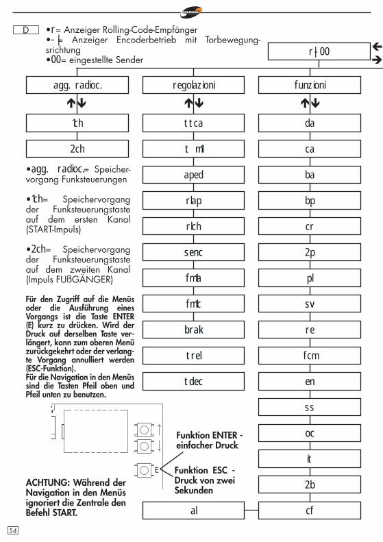
D
r|-00
agg. radioc.
1ch
regolazioni
ttca
funzioni
ca
ba
fm1a
fm1c
bp
cr
2p
pl
re
ss
it
cfal
•agg. radioc.= Speicher-vorgang Funksteuerungen
•1ch= Speichervorgang der Funksteuerungstaste auf dem ersten Kanal (START-Impuls)
•2ch= Speichervorgang der Funksteuerungstaste auf dem zweiten Kanal (Impuls FUßGÄNGER)
Für den Zugriff auf die Menüs oder die Ausführung eines Vorgangs ist die Taste ENTER (E) kurz zu drücken. Wird der Druck auf derselben Taste ver-längert, kann zum oberen Menü zurückgekehrt oder der verlang-te Vorgang annulliert werden (ESC-Funktion).Für die Navigation in den Menüs sind die Tasten Pfeil oben und Pfeil unten zu benutzen.
E
•r= Anzeiger Rolling-Code-Empfänger•-|= Anzeiger Encoderbetrieb mit Torbewegung-srichtung•00= eingestellte Sender
ACHTUNG: Während der Navigation in den Menüs ignoriert die Zentrale den Befehl START.
t m1
da
fcm
2b
2ch
Funktion ENTER - einfacher Druck
Funktion ESC - Druck von zwei Sekunden
sv
en
oc
aped
senc
brak
trel
tdec
rlap
rlch
54
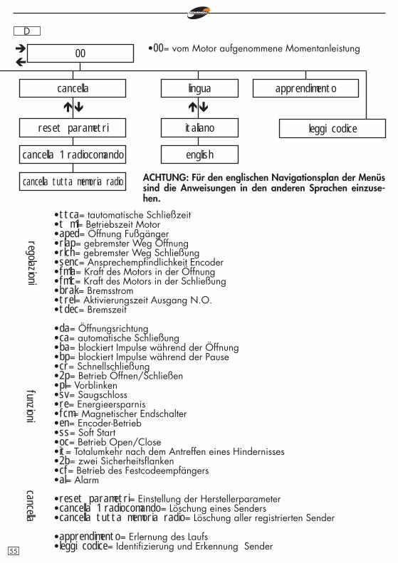
D
00
cancella
reset parametri
cancella 1 radiocomando
lingua
italiano
english
apprendimento
leggi codice
cancella tutta memoria radio
•ttca= tautomatische Schließzeit•t m1= Betriebszeit Motor•aped= Öffnung Fußgänger•rlap= gebremster Weg Öffnung•rlch= gebremster Weg Schließung•senc= Ansprechempfi ndlichkeit Encoder•fm1a= Kraft des Motors in der Öffnung•fm1c= Kraft des Motors in der Schließung•brak= Bremsstrom•trel= Aktivierungszeit Ausgang N.O.•tdec= Bremszeit
•da= Öffnungsrichtung•ca= automatische Schließung•ba= blockiert Impulse während der Öffnung•bp= blockiert Impulse während der Pause•cr= Schnellschließung•2p= Betrieb Öffnen/Schließen•pl= Vorblinken•sv= Saugschloss•re= Energieersparnis•fcm= Magnetischer Endschalter•en= Encoder-Betrieb•ss= Soft Start•oc= Betrieb Open/Close•it= Totalumkehr nach dem Antreffen eines Hindernisses•2b= zwei Sicherheitsfl anken•cf= Betrieb des Festcodeempfängers•al= Alarm
•reset parametri= Einstellung der Herstellerparameter•cancella 1 radiocomando= Löschung eines Senders•cancella tutta memoria radio= Löschung aller registrierten Sender
•apprendimento= Erlernung des Laufs•leggi codice= Identifi zierung und Erkennung Sender
regolazionifunzioni
•00= vom Motor aufgenommene Momentanleistung
cancella
ACHTUNG: Für den englischen Navigationsplan der Menüs sind die Anweisungen in den anderen Sprachen einzuse-hen.
55
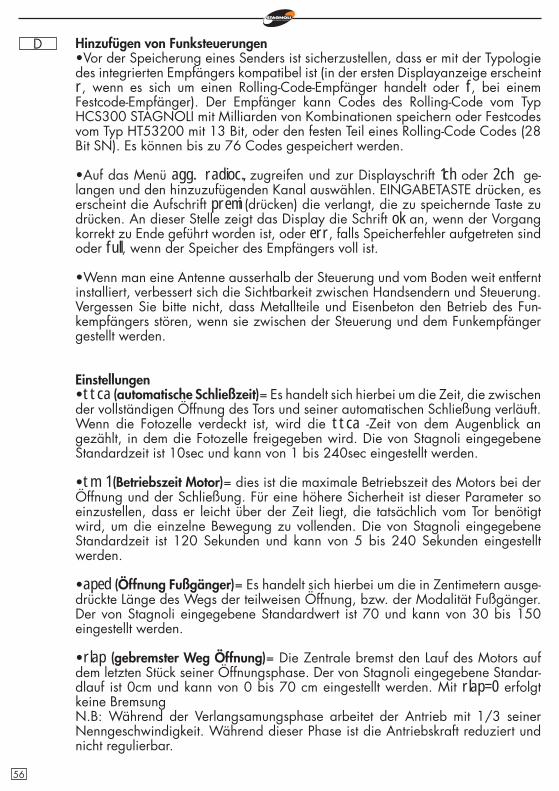
D Hinzufügen von Funksteuerungen•Vor der Speicherung eines Senders ist sicherzustellen, dass er mit der Typologie des integrierten Empfängers kompatibel ist (in der ersten Displayanzeige erscheint r, wenn es sich um einen Rolling-Code-Empfänger handelt oder f, bei einem Festcode-Empfänger). Der Empfänger kann Codes des Rolling-Code vom Typ HCS300 STAGNOLI mit Milliarden von Kombinationen speichern oder Festcodes vom Typ HT53200 mit 13 Bit, oder den festen Teil eines Rolling-Code Codes (28 Bit SN). Es können bis zu 76 Codes gespeichert werden.
•Auf das Menü agg. radioc., zugreifen und zur Displayschrift 1ch oder 2ch ge-langen und den hinzuzufügenden Kanal auswählen. EINGABETASTE drücken, es erscheint die Aufschrift premi (drücken) die verlangt, die zu speichernde Taste zu drücken. An dieser Stelle zeigt das Display die Schrift ok an, wenn der Vorgang korrekt zu Ende geführt worden ist, oder err, falls Speicherfehler aufgetreten sind oder full, wenn der Speicher des Empfängers voll ist.
•Wenn man eine Antenne ausserhalb der Steuerung und vom Boden weit entfernt installiert, verbessert sich die Sichtbarkeit zwischen Handsendern und Steuerung. Vergessen Sie bitte nicht, dass Metallteile und Eisenbeton den Betrieb des Fun-kempfängers stören, wenn sie zwischen der Steuerung und dem Funkempfänger gestellt werden.
Einstellungen•ttca (automatische Schließzeit)= Es handelt sich hierbei um die Zeit, die zwischen der vollständigen Öffnung des Tors und seiner automatischen Schließung verläuft. Wenn die Fotozelle verdeckt ist, wird die ttca -Zeit von dem Augenblick an gezählt, in dem die Fotozelle freigegeben wird. Die von Stagnoli eingegebene Standardzeit ist 10sec und kann von 1 bis 240sec eingestellt werden.
•tm 1 (Betriebszeit Motor)= dies ist die maximale Betriebszeit des Motors bei der Öffnung und der Schließung. Für eine höhere Sicherheit ist dieser Parameter so einzustellen, dass er leicht über der Zeit liegt, die tatsächlich vom Tor benötigt wird, um die einzelne Bewegung zu vollenden. Die von Stagnoli eingegebene Standardzeit ist 120 Sekunden und kann von 5 bis 240 Sekunden eingestellt werden.
•aped (Öffnung Fußgänger)= Es handelt sich hierbei um die in Zentimetern ausge-drückte Länge des Wegs der teilweisen Öffnung, bzw. der Modalität Fußgänger. Der von Stagnoli eingegebene Standardwert ist 70 und kann von 30 bis 150 eingestellt werden.
•rlap (gebremster Weg Öffnung)= Die Zentrale bremst den Lauf des Motors auf dem letzten Stück seiner Öffnungsphase. Der von Stagnoli eingegebene Standar-dlauf ist 0cm und kann von 0 bis 70 cm eingestellt werden. Mit rlap=0 erfolgt keine BremsungN.B: Während der Verlangsamungsphase arbeitet der Antrieb mit 1/3 seiner Nenngeschwindigkeit. Während dieser Phase ist die Antriebskraft reduziert und nicht regulierbar.
56
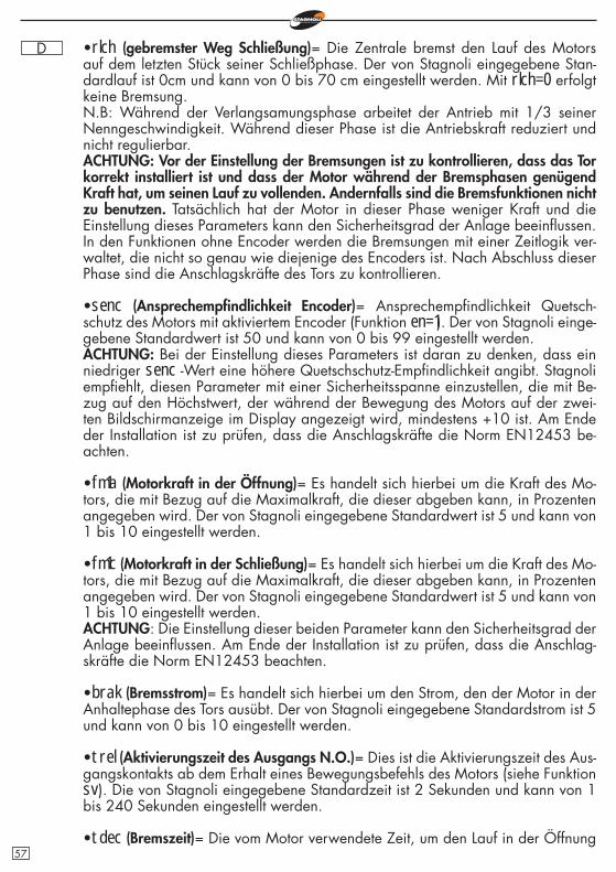
D •rlch (gebremster Weg Schließung)= Die Zentrale bremst den Lauf des Motors auf dem letzten Stück seiner Schließphase. Der von Stagnoli eingegebene Stan-dardlauf ist 0cm und kann von 0 bis 70 cm eingestellt werden. Mit rlch=0 erfolgt keine Bremsung.N.B: Während der Verlangsamungsphase arbeitet der Antrieb mit 1/3 seiner Nenngeschwindigkeit. Während dieser Phase ist die Antriebskraft reduziert und nicht regulierbar.ACHTUNG: Vor der Einstellung der Bremsungen ist zu kontrollieren, dass das Tor korrekt installiert ist und dass der Motor während der Bremsphasen genügend Kraft hat, um seinen Lauf zu vollenden. Andernfalls sind die Bremsfunktionen nicht zu benutzen. Tatsächlich hat der Motor in dieser Phase weniger Kraft und die Einstellung dieses Parameters kann den Sicherheitsgrad der Anlage beeinfl ussen. In den Funktionen ohne Encoder werden die Bremsungen mit einer Zeitlogik ver-waltet, die nicht so genau wie diejenige des Encoders ist. Nach Abschluss dieser Phase sind die Anschlagskräfte des Tors zu kontrollieren.
•senc (Ansprechempfi ndlichkeit Encoder)= Ansprechempfi ndlichkeit Quetsch-schutz des Motors mit aktiviertem Encoder (Funktion en=1). Der von Stagnoli einge-gebene Standardwert ist 50 und kann von 0 bis 99 eingestellt werden.ACHTUNG: Bei der Einstellung dieses Parameters ist daran zu denken, dass ein niedriger senc -Wert eine höhere Quetschschutz-Empfi ndlichkeit angibt. Stagnoli empfi ehlt, diesen Parameter mit einer Sicherheitsspanne einzustellen, die mit Be-zug auf den Höchstwert, der während der Bewegung des Motors auf der zwei-ten Bildschirmanzeige im Display angezeigt wird, mindestens +10 ist. Am Ende der Installation ist zu prüfen, dass die Anschlagskräfte die Norm EN12453 be-achten.
•fm1a (Motorkraft in der Öffnung)= Es handelt sich hierbei um die Kraft des Mo-tors, die mit Bezug auf die Maximalkraft, die dieser abgeben kann, in Prozenten angegeben wird. Der von Stagnoli eingegebene Standardwert ist 5 und kann von 1 bis 10 eingestellt werden.
•fm1c (Motorkraft in der Schließung)= Es handelt sich hierbei um die Kraft des Mo-tors, die mit Bezug auf die Maximalkraft, die dieser abgeben kann, in Prozenten angegeben wird. Der von Stagnoli eingegebene Standardwert ist 5 und kann von 1 bis 10 eingestellt werden.ACHTUNG: Die Einstellung dieser beiden Parameter kann den Sicherheitsgrad der Anlage beeinfl ussen. Am Ende der Installation ist zu prüfen, dass die Anschlag-skräfte die Norm EN12453 beachten.
•brak (Bremsstrom)= Es handelt sich hierbei um den Strom, den der Motor in der Anhaltephase des Tors ausübt. Der von Stagnoli eingegebene Standardstrom ist 5 und kann von 0 bis 10 eingestellt werden.
•trel (Aktivierungszeit des Ausgangs N.O.)= Dies ist die Aktivierungszeit des Aus-gangskontakts ab dem Erhalt eines Bewegungsbefehls des Motors (siehe Funktion sv). Die von Stagnoli eingegebene Standardzeit ist 2 Sekunden und kann von 1 bis 240 Sekunden eingestellt werden.
•tdec (Bremszeit)= Die vom Motor verwendete Zeit, um den Lauf in der Öffnung 57
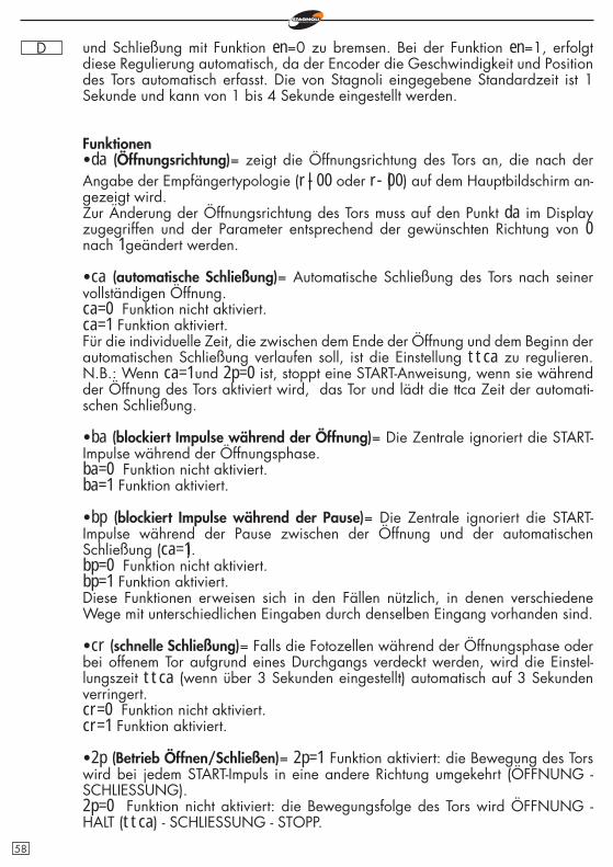
D und Schließung mit Funktion en=0 zu bremsen. Bei der Funktion en=1, erfolgt diese Regulierung automatisch, da der Encoder die Geschwindigkeit und Position des Tors automatisch erfasst. Die von Stagnoli eingegebene Standardzeit ist 1 Sekunde und kann von 1 bis 4 Sekunde eingestellt werden.
Funktionen•da (Öffnungsrichtung)= zeigt die Öffnungsrichtung des Tors an, die nach der Angabe der Empfängertypologie (r|-00 oder r-|00) auf dem Hauptbildschirm an-gezeigt wird.Zur Änderung der Öffnungsrichtung des Tors muss auf den Punkt da im Display zugegriffen und der Parameter entsprechend der gewünschten Richtung von 0 nach 1 geändert werden.
•ca (automatische Schließung)= Automatische Schließung des Tors nach seiner vollständigen Öffnung.ca=0 Funktion nicht aktiviert.ca=1 Funktion aktiviert.Für die individuelle Zeit, die zwischen dem Ende der Öffnung und dem Beginn der automatischen Schließung verlaufen soll, ist die Einstellung ttca zu regulieren. N.B.: Wenn ca=1 und 2p=0 ist, stoppt eine START-Anweisung, wenn sie während der Öffnung des Tors aktiviert wird, das Tor und lädt die ttca Zeit der automati-schen Schließung.
•ba (blockiert Impulse während der Öffnung)= Die Zentrale ignoriert die START-Impulse während der Öffnungsphase.ba=0 Funktion nicht aktiviert.ba=1 Funktion aktiviert.
•bp (blockiert Impulse während der Pause)= Die Zentrale ignoriert die START-Impulse während der Pause zwischen der Öffnung und der automatischen Schließung (ca=1).bp=0 Funktion nicht aktiviert.bp=1 Funktion aktiviert.Diese Funktionen erweisen sich in den Fällen nützlich, in denen verschiedene Wege mit unterschiedlichen Eingaben durch denselben Eingang vorhanden sind.
•cr (schnelle Schließung)= Falls die Fotozellen während der Öffnungsphase oder bei offenem Tor aufgrund eines Durchgangs verdeckt werden, wird die Einstel-lungszeit ttca (wenn über 3 Sekunden eingestellt) automatisch auf 3 Sekunden verringert.cr=0 Funktion nicht aktiviert.cr=1 Funktion aktiviert.
•2p (Betrieb Öffnen/Schließen)= 2p=1 Funktion aktiviert: die Bewegung des Tors wird bei jedem START-Impuls in eine andere Richtung umgekehrt (ÖFFNUNG - SCHLIESSUNG).2p=0 Funktion nicht aktiviert: die Bewegungsfolge des Tors wird ÖFFNUNG - HALT (ttca) - SCHLIESSUNG - STOPP.
58
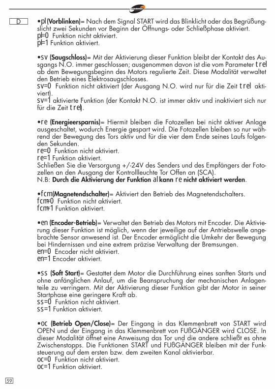
D •pl (Vorblinken)= Nach dem Signal START wird das Blinklicht oder das Begrüßung-slicht zwei Sekunden vor Beginn der Öffnungs- oder Schließphase aktiviert.pl=0 Funktion nicht aktiviert.pl=1 Funktion aktiviert.
•sv (Saugschloss)= Mit der Aktivierung dieser Funktion bleibt der Kontakt des Au-sgangs N.O. immer geschlossen; ausgenommen davon ist die vom Parameter trel ab dem Bewegungsbeginn des Motors regulierte Zeit. Diese Modalität verwaltet den Betrieb eines Elektrosaugschlosses.sv=0 Funktion nicht aktiviert (der Ausgang N.O. wird nur für die Zeit trel akti-viert).sv=1 aktivierte Funktion (der Kontakt N.O. ist immer aktiv und inaktiviert sich nur für die Zeit trel).
•re (Energieersparnis)= Hiermit bleiben die Fotozellen bei nicht aktiver Anlage ausgeschaltet, wodurch Energie gespart wird. Die Fotozellen bleiben so nur wäh-rend der Bewegung des Tors aktiv und für die vier dem Ende seines Laufs folgen-den Sekunden.re=0 Funktion nicht aktiviert.re=1 Funktion aktiviert.Schließen Sie die Versorgung +/-24V des Senders und des Empfängers der Foto-zellen an den Ausgang der Kontrollleuchte Tor Offen an (SCA).N.B: Durch die Aktivierung der Funktion al kann re nicht aktiviert werden.
•fcm (Magnetendschalter)= Aktiviert den Betrieb des Magnetendschalters.fcm=0 Funktion nicht aktiviert.fcm=1 Funktion aktiviert.
•en (Encoder-Betrieb)= Verwaltet den Betrieb des Motors mit Encoder. Die Aktivie-rung dieser Funktion ist möglich, wenn der jeweilige auf der Antriebswelle ange-brachte Sensor anwesend ist. Der Encoder ermöglicht die Umkehr der Bewegung bei Hindernissen und eine extrem präzise Verwaltung der Bremsungen.en=0 Encoder nicht aktiviert.en=1 Encoder aktiviert.
•ss (Soft Start)= Gestattet dem Motor die Durchführung eines sanften Starts und ohne anfänglichen Anlauf, um die Beanspruchung der mechanischen Anlagen-teile zu verringern. Mit der Aktivierung dieser Funktion gibt der Motor in seiner Startphase eine geringere Kraft ab.ss=0 Funktion nicht aktiviert.ss=1 Funktion aktiviert.
•oc (Betrieb Open/Close)= Der Eingang in das Klemmenbrett von START wird OPEN und der Eingang in das Klemmenbrett von FUßGÄNGER wird CLOSE. In dieser Modalität öffnet eine Anweisung das Tor und die andere schließt es ohne Zwischenstopps. Die Funktionen START und FUßGÄNGER bleiben mit der Funk-steuerung auf dem ersten bzw. dem zweiten Kanal aktivierbar.oc=0 Funktion nicht aktiviert.oc=1 Funktion aktiviert.
59
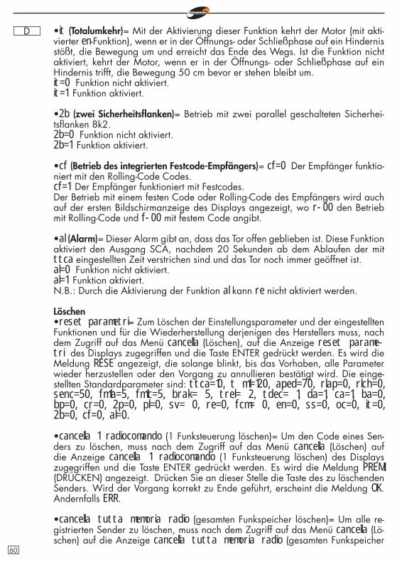
D •it (Totalumkehr)= Mit der Aktivierung dieser Funktion kehrt der Motor (mit akti-vierter en-Funktion), wenn er in der Öffnungs- oder Schließphase auf ein Hindernis stößt, die Bewegung um und erreicht das Ende des Wegs. Ist die Funktion nicht aktiviert, kehrt der Motor, wenn er in der Öffnungs- oder Schließphase auf ein Hindernis trifft, die Bewegung 50 cm bevor er stehen bleibt um.it=0 Funktion nicht aktiviert.it=1 Funktion aktiviert.
•2b (zwei Sicherheitsfl anken)= Betrieb mit zwei parallel geschalteten Sicherhei-tsfl anken 8k2.2b=0 Funktion nicht aktiviert.2b=1 Funktion aktiviert.
•cf (Betrieb des integrierten Festcode-Empfängers)= cf=0 Der Empfänger funktio-niert mit den Rolling-Code Codes.cf=1 Der Empfänger funktioniert mit Festcodes.Der Betrieb mit einem festen Code oder Rolling-Code des Empfängers wird auch auf der ersten Bildschirmanzeige des Displays angezeigt, wo r-00 den Betrieb mit Rolling-Code und f-00 mit festem Code angibt.
•al (Alarm)= Dieser Alarm gibt an, dass das Tor offen geblieben ist. Diese Funktion aktiviert den Ausgang SCA, nachdem 20 Sekunden ab dem Ablaufen der mit ttca eingestellten Zeit verstrichen sind und das Tor noch immer geöffnet ist.al=0 Funktion nicht aktiviert.al=1 Funktion aktiviert.N.B.: Durch die Aktivierung der Funktion al kann re nicht aktiviert werden.
Löschen•reset parametri= Zum Löschen der Einstellungsparameter und der eingestellten Funktionen und für die Wiederherstellung derjenigen des Herstellers muss, nach dem Zugriff auf das Menü cancella (Löschen), auf die Anzeige reset parame-tri des Displays zugegriffen und die Taste ENTER gedrückt werden. Es wird die Meldung RESE angezeigt, die solange blinkt, bis das Vorhaben, alle Parameter wieder herzustellen oder den Vorgang zu annullieren bestätigt wird. Die einge-stellten Standardparameter sind: ttca=10, t m1=120, aped=70, rlap=0, rlch=0, senc=50, fm1a=5, fm1c=5, brak= 5, trel= 2, tdec= 1, da=1, ca=1, ba=0, bp=0, cr=0, 2p=0, pl=0, sv= 0, re=0, fcm= 0, en=0, ss=0, oc=0, it=0, 2b=0, cf=0, al=0.
•cancella 1 radiocomando (1 Funksteuerung löschen)= Um den Code eines Sen-ders zu löschen, muss nach dem Zugriff auf das Menü cancella (Löschen) auf die Anzeige cancella 1 radiocomando (1 Funksteuerung löschen) des Displays zugegriffen und die Taste ENTER gedrückt werden. Es wird die Meldung PREMI (DRÜCKEN) angezeigt. Drücken Sie an dieser Stelle die Taste des zu löschenden Senders. Wird der Vorgang korrekt zu Ende geführt, erscheint die Meldung OK. Andernfalls ERR.
•cancella tutta memoria radio (gesamten Funkspeicher löschen)= Um alle re-gistrierten Sender zu löschen, muss nach dem Zugriff auf das Menü cancella (Lö-schen) auf die Anzeige cancella tutta memoria radio (gesamten Funkspeicher
60
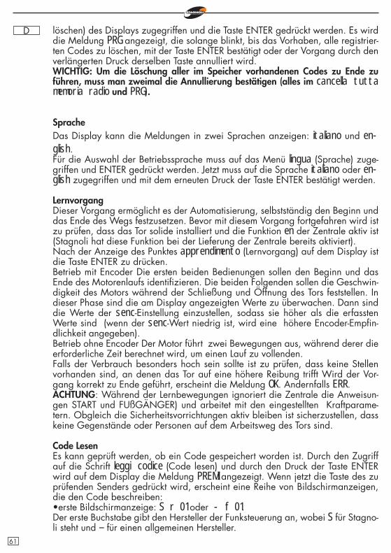
D löschen) des Displays zugegriffen und die Taste ENTER gedrückt werden. Es wird die Meldung PRG angezeigt, die solange blinkt, bis das Vorhaben, alle registrier-ten Codes zu löschen, mit der Taste ENTER bestätigt oder der Vorgang durch den verlängerten Druck derselben Taste annulliert wird.WICHTIG: Um die Löschung aller im Speicher vorhandenen Codes zu Ende zu führen, muss man zweimal die Annullierung bestätigen (alles im cancella tutta memoria radio und PRG).
SpracheDas Display kann die Meldungen in zwei Sprachen anzeigen: italiano und en-glish.Für die Auswahl der Betriebssprache muss auf das Menü lingua (Sprache) zuge-griffen und ENTER gedrückt werden. Jetzt muss auf die Sprache italiano oder en-glish zugegriffen und mit dem erneuten Druck der Taste ENTER bestätigt werden.
LernvorgangDieser Vorgang ermöglicht es der Automatisierung, selbstständig den Beginn und das Ende des Wegs festzusetzen. Bevor mit diesem Vorgang fortgefahren wird ist zu prüfen, dass das Tor solide installiert und die Funktion en der Zentrale aktiv ist (Stagnoli hat diese Funktion bei der Lieferung der Zentrale bereits aktiviert).Nach der Anzeige des Punktes apprendimento (Lernvorgang) auf dem Display ist die Taste ENTER zu drücken.Betrieb mit Encoder Die ersten beiden Bedienungen sollen den Beginn und das Ende des Motorenlaufs identifi zieren. Die beiden Folgenden sollen die Geschwin-digkeit des Motors während der Schließung und Öffnung des Tors feststellen. In dieser Phase sind die am Display angezeigten Werte zu überwachen. Dann sind die Werte der senc-Einstellung einzustellen, sodass sie höher als die erfassten Werte sind (wenn der senc-Wert niedrig ist, wird eine höhere Encoder-Empfi n-dlichkeit angegeben).Betrieb ohne Encoder Der Motor führt zwei Bewegungen aus, während derer die erforderliche Zeit berechnet wird, um einen Lauf zu vollenden. Falls der Verbrauch besonders hoch sein sollte ist zu prüfen, dass keine Stellen vorhanden sind, an denen das Tor auf eine höhere Reibung trifft Wird der Vor-gang korrekt zu Ende geführt, erscheint die Meldung OK. Andernfalls ERR.ACHTUNG: Während der Lernbewegungen ignoriert die Zentrale die Anweisun-gen START und FUßGÄNGER) und arbeitet mit den eingestellten Kraftparame-tern. Obgleich die Sicherheitsvorrichtungen aktiv bleiben ist sicherzustellen, dass keine Gegenstände oder Personen auf dem Arbeitsweg des Tors sind.
Code LesenEs kann geprüft werden, ob ein Code gespeichert worden ist. Durch den Zugriff auf die Schrift leggi codice (Code lesen) und durch den Druck der Taste ENTER wird auf dem Display die Meldung PREMI angezeigt. Wenn jetzt die Taste des zu prüfenden Senders gedrückt wird, erscheint eine Reihe von Bildschirmanzeigen, die den Code beschreiben:•erste Bildschirmanzeige: S r 01 oder - f 01.Der erste Buchstabe gibt den Hersteller der Funksteuerung an, wobei S für Stagno-li steht und – für einen allgemeinen Hersteller.
61
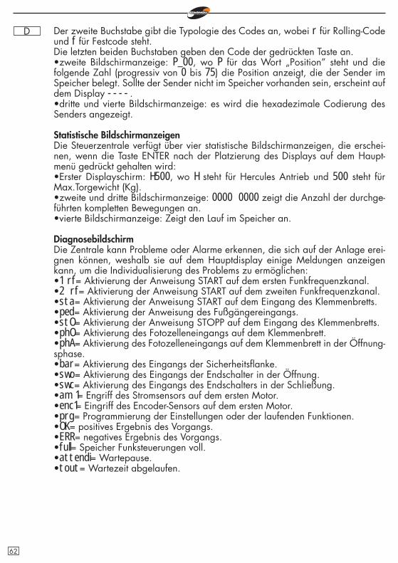
D Der zweite Buchstabe gibt die Typologie des Codes an, wobei r für Rolling-Code und f für Festcode steht.Die letzten beiden Buchstaben geben den Code der gedrückten Taste an.•zweite Bildschirmanzeige: P_00, wo P für das Wort „Position” steht und die folgende Zahl (progressiv von 0 bis 75) die Position anzeigt, die der Sender im Speicher belegt. Sollte der Sender nicht im Speicher vorhanden sein, erscheint auf dem Display ----.•dritte und vierte Bildschirmanzeige: es wird die hexadezimale Codierung des Senders angezeigt.
Statistische BildschirmanzeigenDie Steuerzentrale verfügt über vier statistische Bildschirmanzeigen, die erschei-nen, wenn die Taste ENTER nach der Platzierung des Displays auf dem Haupt-menü gedrückt gehalten wird:•Erster Displayschirm: H500, wo H steht für Hercules Antrieb und 500 steht für Max.Torgewicht (Kg).•zweite und dritte Bildschirmanzeige: 0000 0000 zeigt die Anzahl der durchge-führten kompletten Bewegungen an.•vierte Bildschirmanzeige: Zeigt den Lauf im Speicher an.
DiagnosebildschirmDie Zentrale kann Probleme oder Alarme erkennen, die sich auf der Anlage erei-gnen können, weshalb sie auf dem Hauptdisplay einige Meldungen anzeigen kann, um die Individualisierung des Problems zu ermöglichen:•1 rf= Aktivierung der Anweisung START auf dem ersten Funkfrequenzkanal.•2 rf= Aktivierung der Anweisung START auf dem zweiten Funkfrequenzkanal.•sta= Aktivierung der Anweisung START auf dem Eingang des Klemmenbretts.•ped= Aktivierung der Anweisung des Fußgängereingangs.•stO= Aktivierung der Anweisung STOPP auf dem Eingang des Klemmenbretts.•phO= Aktivierung des Fotozelleneingangs auf dem Klemmenbrett.•phA= Aktivierung des Fotozelleneingangs auf dem Klemmenbrett in der Öffnung-sphase.•bar= Aktivierung des Eingangs der Sicherheitsfl anke. •swo= Aktivierung des Eingangs der Endschalter in der Öffnung.•swc= Aktivierung des Eingangs des Endschalters in der Schließung.•am 1= Engriff des Stromsensors auf dem ersten Motor.•enc1= Eingriff des Encoder-Sensors auf dem ersten Motor.•prg= Programmierung der Einstellungen oder der laufenden Funktionen.•OK= positives Ergebnis des Vorgangs.•ERR= negatives Ergebnis des Vorgangs.•full= Speicher Funksteuerungen voll.•attendi= Wartepause.•tout= Wartezeit abgelaufen.
62
D
Technische Angaben•Speisung der Automatik: 230V - 50/60Hz.•Primäre Schutzsicherung Transformator: F5A/230V.•Schutzsicherung des Ausgangs Zubehör 24V: T1A.•Integrierter Empfänger (433Mhz): Maximales Fassungsvermögen 76 Funkcodes.•Betriebstemperatur: -20° +55°•Maximale Nennleistung des Motors: 500W•Maximale Leistung des Blinklichtausgangs: 40W•Maximale Leistung des Kontrollleuchtenausgangs Tor offen (SCA): 5W
F.A.Q. - Häufi g gestellte Fragen
Weshalb eher einen Sender mit Rolling-Code als einen mit Festcode wählen?Die Rolling-Code-Sender gelten als die sichersten, da sie nicht geklont werden kön-nen und über 200 Millionen Kombinationen haben, die sich bei jeder Übertragung ändern. Die Festcode-Sender verfügen dagegen über 1024 Codekombinationen, die sich nicht bei jeder Übertragung ändern.
Die Zentrale erkennt den Sender nicht an. Warum?Prüfen Sie, dass Zentrale und Sender vom gleichen Typ sind. In der ersten Hauptbild-schirmanzeige kann der Typ des von der Zentrale verwendeten Empfängers festgestellt und eventuell geändert werden, indem der Parameter cf eingestellt wird.
63
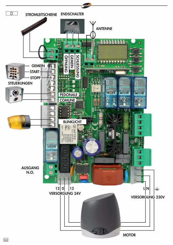
D STROMLEITSCHIENE
STEUERUNGEN
COMUNEPEDONALE
BLINKLICHT
012 12 L N
ENDSCHALTER
MOTOR
GEMEIN
STOPP
START
SCHLIESSU
NG
GEM
EINÖ
FFNU
NG
ANTENNE
VERSORGUNG 24VVERSORGUNG 230V
AUSGANG N.O.
64

D
ENCO
DER
MO
TOR
BLINKLICHT
KONDENSATOR
SCHLIESSUNGGEMEINÖFFNUNG
FOTO
ZELL
EN D
ER
SCH
LIES
SUN
GFO
TOZE
LLEN
IN
ÖFF
NU
NG
TXRX
RXTX
ALIMENTAZIONE FOTOCELLULE
GEMEIN
FOTOZELLEN DER SCHLIESSUNGFOTOZELLEN IN ÖFFNUNG UND SCHLIESSUNG
65
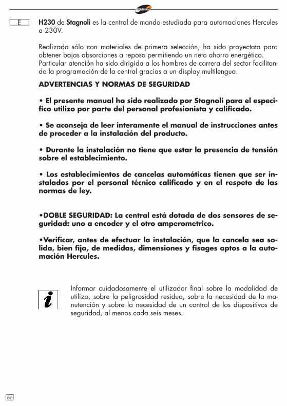
E H230 de Stagnoli es la central de mando estudiada para automaciones Hercules a 230V.
Realizada sólo con materiales de primera selección, ha sido proyectata para obtener bajas absorciones a reposo permitiendo un neto ahorro energético.Particular atención ha sido dirigida a los hombres de carrera del sector facilitan-do la programación de la central gracias a un display multilengua.
ADVERTENCIAS Y NORMAS DE SEGURIDAD
• El presente manual ha sido realizado por Stagnoli para el especi-fi co utilizo por parte del personal profesionista y califi cado.
• Se aconseja de leer interamente el manual de instrucciones antes de proceder a la instalación del producto.
• Durante la instalación no tiene que estar la presencia de tensión sobre el establecimiento.
• Los establecimientos de cancelas automáticas tienen que ser in-stalados por el personal técnico califi cado y en el respeto de las normas de ley.
•DOBLE SEGURIDAD: La central está dotada de dos sensores de se-guridad: uno a encoder y el otro amperometrico.
•Verifi car, antes de efectuar la instalación, que la cancela sea so-lida, bien fi ja, de medidas, dimensiones y fi sages aptos a la auto-mación Hercules.
Informar cuidadosamente el utilizador fi nal sobre la modalidad de utilizo, sobre la peligrosidad residua, sobre la necesidad de la ma-nutención y sobre la necesidad de un control de los dispositivos de seguridad, al menos cada seis meses.
66
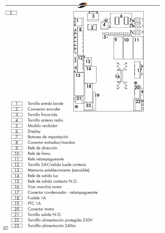
E
789
101112131415161718
Botones de impostaciónConector entradas/mandosRelé de direcciónRelé de frenoRelé relampagueanteTornillo 24V/salida luzde cortesiaMemoria establecimiento (estraiible)Relé de salida luzRelé de salida contacto N.O.Triac marchia motorConector condensador - relampagueanteFusible 1A
19 PTC 1A20 Conector motor21 Tornillo salida N.O.22 Tornilllo alimentación protegida 230V
654321
DisplayModúlo recibidorTornillo antena radioTornillo fi ncorridaConnector encoderTornillo entrda borde
1
20
19
18
171615
14
1312
11109
8
7a6
5
4
3
2 7b7c
2322
21
23 Tornilllo alimentación 24Vac67
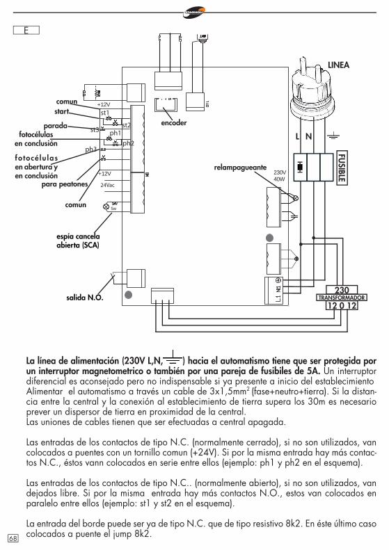
E
La línea de alimentación (230V L,N, ) hacia el automatismo tiene que ser protegida por un interruptor magnetometrico o también por una pareja de fusibiles de 5A. Un interruptor diferencial es aconsejado pero no indispensable si ya presente a inicio del establecimientoAlimentar el automatismo a través un cable de 3x1,5mm2
(fase+neutro+tierra). Si la distan-cia entre la central y la conexión al establecimiento de tierra supera los 30m es necesario prever un dispersor de tierra en proximidad de la central.Las uniones de cables tienen que ser efectuadas a central apagada.
Las entradas de los contactos de tipo N.C. (normalmente cerrado), si no son utilizados, van colocados a puentes con un tornillo comun (+24V). Si por la misma entrada hay más contac-tos N.C., éstos vann colocados en serie entre ellos (ejemplo: ph1 y ph2 en el esquema).
Las entradas de los contactos de tipo N.C.. (normalmente abierto), si no son utilizados, van dejados libre. Si por la misma entrada hay más contactos N.O., estos van colocados en paralelo entre ellos (ejemplo: st1 y st2 en el esquema).
La entrada del borde puede ser ya de tipo N.C. que de tipo resistivo 8k2. En éste último caso colocados a puente el jump 8k2.
L N
espía cancela abierta (SCA)
salida N.O.
LINEA
st1
st3
5w
24Vac
+12V
+12V
230V40W
ph1
ph3
st2
ph2
comunstart
paradafotocélulas
en conclusión
fo tocé lu lasen abertura y en conclusión
para peatones
comun
relampagueante
230
12 0 12TRANSFORMADOR
FUSIBLE
encoder
68
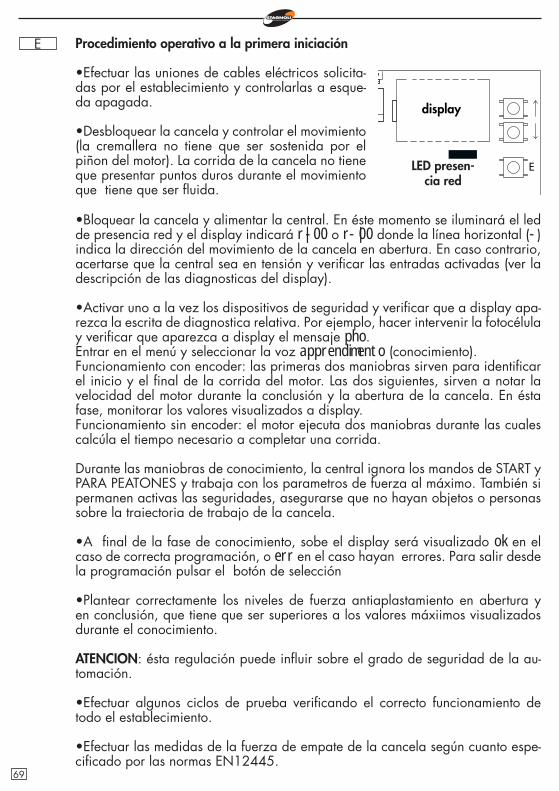
E Procedimiento operativo a la primera iniciación
•Efectuar las uniones de cables eléctricos solicita-das por el establecimiento y controlarlas a esque-da apagada.
•Desbloquear la cancela y controlar el movimiento (la cremallera no tiene que ser sostenida por el piñon del motor). La corrida de la cancela no tiene que presentar puntos duros durante el movimiento que tiene que ser fl uida.
E
•Bloquear la cancela y alimentar la central. En éste momento se iluminará el led de presencia red y el display indicará r|-00 o r-|00 donde la línea horizontal (-) indica la dirección del movimiento de la cancela en abertura. En caso contrario, acertarse que la central sea en tensión y verifi car las entradas activadas (ver la descripción de las diagnosticas del display).
•Activar uno a la vez los dispositivos de seguridad y verifi car que a display apa-rezca la escrita de diagnostica relativa. Por ejemplo, hacer intervenir la fotocélula y verifi car que aparezca a display el mensaje pho.Entrar en el menú y seleccionar la voz apprendimento (conocimiento). Funcionamiento con encoder: las primeras dos maniobras sirven para identifi car el inicio y el fi nal de la corrida del motor. Las dos siguientes, sirven a notar la velocidad del motor durante la conclusión y la abertura de la cancela. En ésta fase, monitorar los valores visualizados a display.Funcionamiento sin encoder: el motor ejecuta dos maniobras durante las cuales calcúla el tiempo necesario a completar una corrida.
Durante las maniobras de conocimiento, la central ignora los mandos de START y PARA PEATONES y trabaja con los parametros de fuerza al máximo. También si permanen activas las seguridades, asegurarse que no hayan objetos o personas sobre la traiectoria de trabajo de la cancela.
•A fi nal de la fase de conocimiento, sobe el display será visualizado ok en el caso de correcta programación, o err en el caso hayan errores. Para salir desde la programación pulsar el botón de selección
•Plantear correctamente los niveles de fuerza antiaplastamiento en abertura y en conclusión, que tiene que ser superiores a los valores máxiimos visualizados durante el conocimiento.
ATENCION: ésta regulación puede infl uir sobre el grado de seguridad de la au-tomación.
•Efectuar algunos ciclos de prueba verifi cando el correcto funcionamiento de todo el establecimiento.
•Efectuar las medidas de la fuerza de empate de la cancela según cuanto espe-cifi cado por las normas EN12445.
display
LED presen-cia red
69
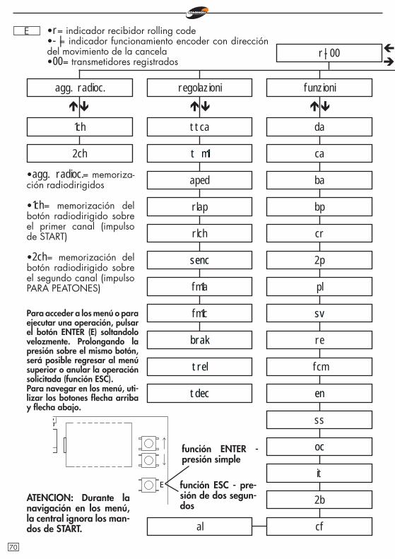
E
r|-00
agg. radioc.
1ch
regolazioni
ttca
funzioni
ca
ba
fm1a
fm1c
bp
cr
2p
pl
re
ss
it
cfal
•agg. radioc.= memoriza-ción radiodirigidos
•1ch= memorización del botón radiodirigido sobre el primer canal (impulso de START)
•2ch= memorización del botón radiodirigido sobre el segundo canal (impulso PARA PEATONES)
Para acceder a los menú o para ejecutar una operación, pulsar el botón ENTER (E) soltandolo velozmente. Prolongando la presión sobre el mismo botón, será posible regresar al menú superior o anular la operación solicitada (función ESC).Para navegar en los menú, uti-lizar los botones fl echa arriba y fl echa abajo.
E
•r= indicador recibidor rolling code•-|= indicador funcionamiento encoder con dirección del movimiento de la cancela•00= transmetidores registrados
ATENCION: Durante la navigación en los menú, la central ignora los man-dos de START.
t m1
da
fcm
2b
2ch
función ENTER - presión simple
función ESC - pre-sión de dos segun-dos
sv
en
oc
aped
senc
brak
trel
tdec
rlap
rlch
70
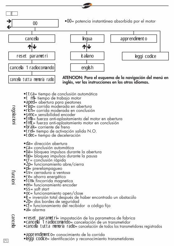
E
00
cancella
reset parametri
cancella 1 radiocomando
lingua
italiano
english
apprendimento
leggi codice
cancella tutta memoria radio
•ttca= tiempo de conclusión automática•t m1= tiempo de trabajo motor•aped= abertura para peatones•rlap= corrida moderada en abertura•rlch= corrida moderada en conclusión•senc= sensibilidad encoder•fm1a= fuerza anti-aplastamiento del motor en abertura•fm1c= fuerza anti-aplastamiento motor en conclusión •brak= corriente de freno•trel= tiempo de activación salida N.O.•tdec= tiempo de deceleración
•da= dirección abertura•ca= conclusión automática•ba= bloquea impulsos durante la abertura•bp= bloquea impulsos durante la pausa•cr= conclusión rápida•2p= funcionamiento abre/cierra•pl= prerelampagueo•sv= cerradura a ventosa•re= ahorro energético•fcm= fi ncorrida magnetica•en= funcionamiento encoder•ss= soft start•oc= funcionamiento open/close•it= inversión total después de haber encontrado un obstacúlo•2b= dos bordes de seguridad•cf= funcionamiento del recibidor a código fi jo•al= alarma
•reset parametri= impostación de los parametros de fabrica•cancella 1 radiocomando= cancelación de un transmetidor•cancella tutta memoria radio= cancelación de todos los transmetidores registrados
•apprendimento= conocimiento de la corrida•leggi codice= identifi cación y reconocimiento transmetidores
regolazionifunzioni
•00= potencia instantánea absorbida por el motor
cancella
ATENCION: Para el esquema de la navigación del menú en inglés, ver las instrucciones en los otros idiomas.
71
E Adjunta radiodirigidos•Antes de memorizar un transmetidor, asegurarse que sea compatible con la tipo-logia de recibidor integrado (en la primera visualización del display aparecerá r, si se trata de un recibidor en modalidad rolling code o f si se trata de un recibidor en modalidad código fi jo). El recibidor puede memorizar códigos rolling code de tipo HCS300 STAGNOLI con miliardos de combinaciones o códigos fi jos de tipo HT53200 a 13 bit o la parte fi ja de un código rolling code (28 bit SN). Es posible memorizar hasta 76 códigos.
•Entrando en el menú agg. radioc., llevarse sobre la escrita a display 1ch o 2ch y escoger el canal que se quiere agregar. Pulsando ENTER, vendrá desde luego visualizada la escrita premi. Pulsar el botón que se desea memorizar: en éste momento el display visualizará la escritta ok si la operación viene concluida de manera correcta, err en el caso se verifi quen errores de registración o full si la memoria del recibidor está llena.
•Al instalar una antena al exterior de la central y cerca del suelo, el area de visi-bilidad entre emisores y central aumenta. Además, no olvidense que los compo-nentes metálicos y de hormigón armado, si se ponen entre la central y el receptor, reducen la recepción de éste.
Regulaciones•ttca (tiempo de conclusión automática)= es el tiempo que transcurre entre la abertura completa de la cancela y su conclusión que sucede en manera automáti-ca. Si la fotocélula está ocupada, el tiempo de ttca viene calculado desde el momento en que la fotocélula se desempeña. El tiempo planteado de default por Stagnoli es 10seg y es regulable de 1 a 240seg.
•tm 1 (tiempo de trabajo motor)= es el tiempo de trabajo máximo del motor en abertura y en conclusión. Para una mayor seguridad regular éste parametro de manera que resulte un poco superior al tiempo realmente utilizado por la cancela para completar la singúla maniobra. El tiempo planteado de default por Stagnoli es 120seg y es regulable de 5 a 240seg.
•aped (abertura para peatones)= es la longitud de la corrida expresa en centime-tros de la abertura parciale, o bien de las modalidades para peatones. El valor planteado de default por Stagnoli es 70 y es regulable de 30 a 150.
•rlap (corrida moderada en abertura)= la central modera la corrida del motor en la parte fi nal de sua fase de abertura.La corrida planteada de default por Stagnoli es 0cm y es regulable de 0 a 70cm. Con rlap=0 no hay ninguna reducciónN.B: Durante las fases de decrecimiento, el motor trabaja a 1/3 de su velocidad nominal. Durante esta fase, la fuerza aplicada al motor se queda reducida y no es regulable.
•rlch (corrida moderada en conclusión)= la central modera la corrida del motor en la parte fi nal de sua fase de conclusión. La corrida planteada de default por Stagnoli es 20cm y es regulable de 0 a 70cm. Con rlch=0 no hay ninguna re-
72
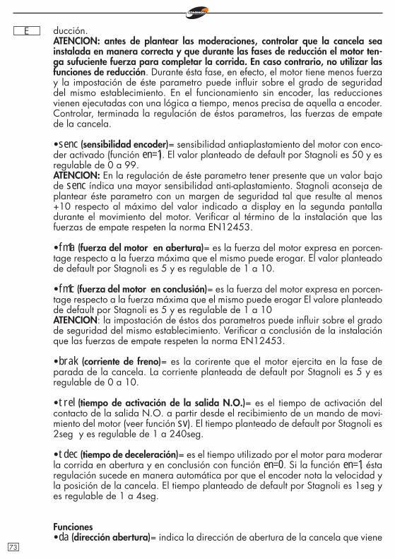
E ducción.ATENCION: antes de plantear las moderaciones, controlar que la cancela sea instalada en manera correcta y que durante las fases de reducción el motor ten-ga sufuciente fuerza para completar la corrida. En caso contrario, no utilizar las funciones de reducción. Durante ésta fase, en efecto, el motor tiene menos fuerza y la impostación de éste parametro puede infl uir sobre el grado de seguridad del mismo establecimiento. En el funcionamiento sin encoder, las reducciones vienen ejecutadas con una lógica a tiempo, menos precisa de aquella a encoder. Controlar, terminada la regulación de éstos parametros, las fuerzas de empate de la cancela.
•senc (sensibilidad encoder)= sensibilidad antiaplastamiento del motor con enco-der activado (función en=1). El valor planteado de default por Stagnoli es 50 y es regulable de 0 a 99.ATENCION: En la regulación de éste parametro tener presente que un valor bajo de senc índica una mayor sensibilidad anti-aplastamiento. Stagnoli aconseja de plantear éste parametro con un margen de seguridad tal que resulte al menos +10 respecto al máximo del valor indicado a display en la segunda pantalla durante el movimiento del motor. Verifi car al término de la instalación que las fuerzas de empate respeten la norma EN12453.
•fm1a (fuerza del motor en abertura)= es la fuerza del motor expresa en porcen-tage respecto a la fuerza máxima que el mismo puede erogar. El valor planteado de default por Stagnoli es 5 y es regulable de 1 a 10.
•fm1c (fuerza del motor en conclusión)= es la fuerza del motor expresa en porcen-tage respecto a la fuerza máxima que el mismo puede erogar El valore planteado de default por Stagnoli es 5 y es regulable de 1 a 10ATENCION: la impostación de éstos dos parametros puede infl uir sobre el grado de seguridad del mismo establecimiento. Verifi car a conclusión de la instalación que las fuerzas de empate respeten la norma EN12453.
•brak (corriente de freno)= es la corirente que el motor ejercita en la fase de parada de la cancela. La corriente planteada de default por Stagnoli es 5 y es regulable de 0 a 10.
•trel (tiempo de activación de la salida N.O.)= es el tiempo de activación del contacto de la salida N.O. a partir desde el recibimiento de un mando de movi-miento del motor (veer función sv). El tiempo planteado de default por Stagnoli es 2seg y es regulable de 1 a 240seg.
•tdec (tiempo de deceleración)= es el tiempo utilizado por el motor para moderar la corrida en abertura y en conclusión con función en=0. Si la función en=1, ésta regulación sucede en manera automática por que el encoder nota la velocidad y la posición de la cancela. El tiempo planteado de default por Stagnoli es 1seg y es regulable de 1 a 4seg.
Funciones•da (dirección abertura)= indica la dirección de abertura de la cancela que viene
73
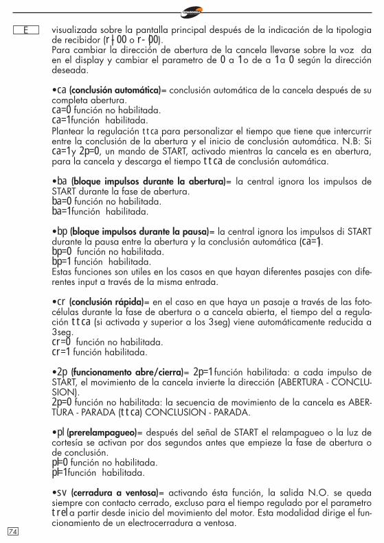
E visualizada sobre la pantalla principal después de la indicación de la tipologia de recibidor (r|-00 o r-|00).Para cambiar la dirección de abertura de la cancela llevarse sobre la voz da en el display y cambiar el parametro de 0 a 1 o de a 1 a 0 según la dirección deseada.
•ca (conclusión automática)= conclusión automática de la cancela después de su completa abertura.ca=0 función no habilitada.ca=1 función habilitada.Plantear la regulación ttca para personalizar el tiempo que tiene que intercurrir entre la conclusión de la abertura y el inicio de conclusión automática. N.B: Si ca=1 y 2p=0, un mando de START, activado mientras la cancela es en abertura, para la cancela y descarga el tiempo ttca de conclusión automática.
•ba (bloque impulsos durante la abertura)= la central ignora los impulsos de START durante la fase de abertura.ba=0 función no habilitada.ba=1 función habilitada.
•bp (bloque impulsos durante la pausa)= la central ignora los impulsos di START durante la pausa entre la abertura y la conclusión automática (ca=1).bp=0 función no habilitada.bp=1 función habilitada.Estas funciones son utiles en los casos en que hayan diferentes pasajes con dife-rentes input a través de la misma entrada.
•cr (conclusión rápida)= en el caso en que haya un pasaje a través de las foto-células durante la fase de abertura o a cancela abierta, el tiempo del a regula-ción ttca (si activada y superior a los 3seg) viene automáticamente reducida a 3seg.cr=0 función no habilitada.cr=1 función habilitada.
•2p (funcionamento abre/cierra)= 2p=1 función habilitada: a cada impulso de START, el movimiento de la cancela invierte la dirección (ABERTURA - CONCLU-SION).2p=0 función no habilitada: la secuencia de movimiento de la cancela es ABER-TURA - PARADA (ttca) CONCLUSION - PARADA.
•pl (prerelampagueo)= después del señal de START el relampagueo o la luz de cortesía se activan por dos segundos antes que empieze la fase de abertura o de conclusión.pl=0 función no habilitada.pl=1 función habilitada.
•sv (cerradura a ventosa)= activando ésta función, la salida N.O. se queda siempre con contacto cerrado, excluso para el tiempo regulado por el parametro trel a partir desde inicio del movimiento del motor. Esta modalidad dirige el fun-cionamiento de un electrocerradura a ventosa.
74
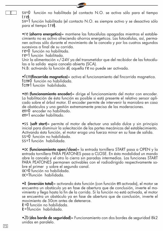
E sv=0 función no habilitada (el contacto N.O. se activa sólo para el tiempo trel).sv=1 función habilitada (el contacto N.O. es siempre activo y se desactiva sólo para el tiempo trel).
•re (ahorro energetico)= mantiene las fotocélulas apagadas mientras el estable-cimiento no es activo ofreciendo ahorros energeticos. Las fotocélulas, así, perma-nen activas sólo durante el movimiento de la cancela y por los cuatros segundos sucesivos a fi nal de su corrida.re=0 función no habilitada.re=1 función habilitada.Unir la alimentación +/-24V ya del transmetidor que del recibidor de las fotocélu-las a la salida espia cancela abierta (SCA).N.B: activando la función al, aquella re no puede ser activada.
•fcm (fi ncorrida magnetica)= activa el funcionamiento del fi ncorrida magnetica.fcm=0 función no habilidada.fcm=1 función habilidada.
•en (funcionamiento encoder)= dirige el funcionamiento del motor con encoder. La habilitación de ésta función es posible si está presente el relativo sensor apli-cado sobre el árbol motor. El encoder permite de intervenir la maniobra en caso de obstáculos y una gestión extremamente precisa de las moderaciones.en=0 encoder no habilitado.en=1 encoder habilitado.
•ss (soft start)= permite al motor de efectuar una salida dulce y sin principio inicial para disminuir la solecitación de las partes mecánicas del establecimiento. Activando ésta función, el motor eroga una fuerza minor en su fase de salida.ss=0 función no habilidada.ss=1 función habilidada.
•oc (funcionamiento open/close)= la entrada tornillera START pasa a OPEN y la entrada tornillera PARA PEATONES pasa a CLOSE. En ésta modalidad un mando abre la cancela y el otro lo cierra sin paradas intermedias. Las funciones START PARA PEATONES permanen activables con el radiodirigido respectivamente so-bre el primer y sobre el segundo canal.oc=0 función no habilidada.oc=1 función habilidada.
•it (inversión total)= activando ésta función (con función en activada), el motor se encuentra un obstáculo ya en fase de abertura que de conclusión, inverte el mo-vimiento y llega hasta la fi n de la corrida. Si la función no está activada, el motor se encuentra un obstáculo ya en fase de abertura que de conclusión, inverte el movimiento de 50cm antes de detenerce.it=0 función no habilidada.it=1 función habilidada.
•2b (dos borde de seguridad)= Funcionamiento con dos bordes de seguridad 8k2 unidas en paralelo.
75
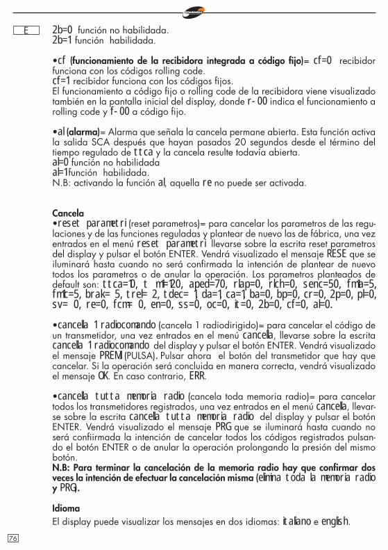
E 2b=0 función no habilidada.2b=1 función habilidada.
•cf (funcionamiento de la recibidora integrada a código fi jo)= cf=0 recibidor funciona con los códigos rolling code.cf=1 recibidor funciona con los códigos fi jos.El funcionamiento a código fi jo o rolling code de la recibidora viene visualizado también en la pantalla inicial del display, donde r-00 indica el funcionamiento a rolling code y f-00 a código fi jo.
•al (alarma)= Alarma que señala la cancela permane abierta. Esta función activa la salida SCA después que hayan pasados 20 segundos desde el término del tiempo regulado de ttca y la cancela resulte todavía abierta.al=0 función no habilidadaal=1 función habilidada.N.B: activando la función al, aquella re no puede ser activada.
Cancela•reset parametri (reset parametros)= para cancelar los parametros de las regu-laciones y de las funciones reguladas y plantear de nuevo las de fábrica, una vez entrados en el menú reset parametri llevarse sobre la escrita reset parametros del display y pulsar el botón ENTER. Vendrá visualizado el mensaje RESE que se iluminará hasta cuando no será confi rmada la intención de plantear de nuevo todos los parametros o de anular la operación. Los parametros planteados de default son: ttca=10, t m1=120, aped=70, rlap=0, rlch=0, senc=50, fm1a=5, fm1c=5, brak= 5, trel= 2, tdec= 1, da=1, ca=1, ba=0, bp=0, cr=0, 2p=0, pl=0, sv= 0, re=0, fcm= 0, en=0, ss=0, oc=0, it=0, 2b=0, cf=0, al=0.
•cancella 1 radiocomando (cancela 1 radiodirigido)= para cancelar el código de un transmetidor, una vez entrados en el menú cancella, llevarse sobre la escrita cancella 1 radiocomando del display y pulsar el botón ENTER. Vendrá visualizado el mensaje PREMI (PULSA). Pulsar ahora el botón del transmetidor que hay que cancelar. Si la operación será concluida en manera correcta, vendrá visualizado el mensaje OK. En caso contrario, ERR.
•cancella tutta memoria radio (cancela toda memoria radio)= para cancelar todos los transmetidores registrados, una vez entrados en el menú cancella, llevar-se sobre la escrita cancella tutta memoria radio del display y pulsar el botón ENTER. Vendrá visualizado el mensaje PRG que se iluminará hasta cuando no será confi irmada la intención de cancelar todos los códigos registrados pulsan-do el botón ENTER o de anular la operación prolongando la presión del mismo botón.N.B: Para terminar la cancelación de la memoria radio hay que confi rmar dos veces la intención de efectuar la cancelación misma (elimina toda la memoria radio y PRG).
IdiomaEl display puede visualizar los mensajes en dos idiomas: italiano e english.
76
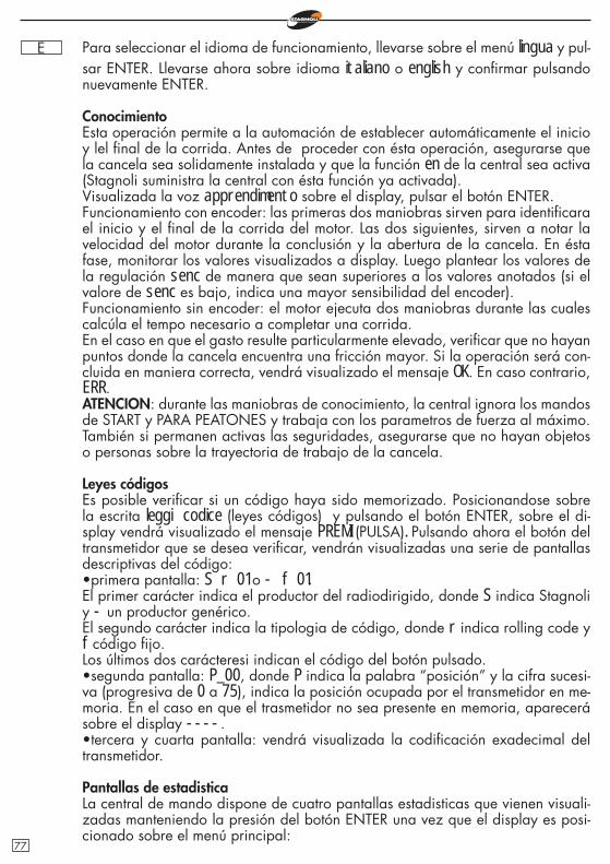
E Para seleccionar el idioma de funcionamiento, llevarse sobre el menú lingua y pul-sar ENTER. Llevarse ahora sobre idioma italiano o english y confi rmar pulsando nuevamente ENTER.
ConocimientoEsta operación permite a la automación de establecer automáticamente el inicio y lel fi nal de la corrida. Antes de proceder con ésta operación, asegurarse que la cancela sea solidamente instalada y que la función en de la central sea activa (Stagnoli suministra la central con ésta función ya activada).Visualizada la voz apprendimento sobre el display, pulsar el botón ENTER.Funcionamiento con encoder: las primeras dos maniobras sirven para identifi cara el inicio y el fi nal de la corrida del motor. Las dos siguientes, sirven a notar la velocidad del motor durante la conclusión y la abertura de la cancela. En ésta fase, monitorar los valores visualizados a display. Luego plantear los valores de la regulación senc de manera que sean superiores a los valores anotados (si el valore de senc es bajo, indica una mayor sensibilidad del encoder).Funcionamiento sin encoder: el motor ejecuta dos maniobras durante las cuales calcúla el tempo necesario a completar una corrida.En el caso en que el gasto resulte particularmente elevado, verifi car que no hayan puntos donde la cancela encuentra una fricción mayor. Si la operación será con-cluida en maniera correcta, vendrá visualizado el mensaje OK. En caso contrario, ERR.ATENCION: durante las maniobras de conocimiento, la central ignora los mandos de START y PARA PEATONES y trabaja con los parametros de fuerza al máximo. También si permanen activas las seguridades, asegurarse que no hayan objetos o personas sobre la trayectoria de trabajo de la cancela.
Leyes códigosEs posible verifi car si un código haya sido memorizado. Posicionandose sobre la escrita leggi codice (leyes códigos) y pulsando el botón ENTER, sobre el di-splay vendrá visualizado el mensaje PREMI (PULSA). Pulsando ahora el botón del transmetidor que se desea verifi car, vendrán visualizadas una serie de pantallas descriptivas del código:•primera pantalla: S r 01 o - f 01.El primer carácter indica el productor del radiodirigido, donde S indica Stagnoli y - un productor genérico.El segundo carácter indica la tipologia de código, donde r indica rolling code y f código fi jo.Los últimos dos carácteresi indican el código del botón pulsado.•segunda pantalla: P_00, donde P indica la palabra “posición” y la cifra sucesi-va (progresiva de 0 a 75), indica la posición ocupada por el transmetidor en me-moria. En el caso en que el trasmetidor no sea presente en memoria, aparecerá sobre el display ----.•tercera y cuarta pantalla: vendrá visualizada la codifi cación exadecimal del transmetidor.
Pantallas de estadisticaLa central de mando dispone de cuatro pantallas estadisticas que vienen visuali-zadas manteniendo la presión del botón ENTER una vez que el display es posi-cionado sobre el menú principal:
77
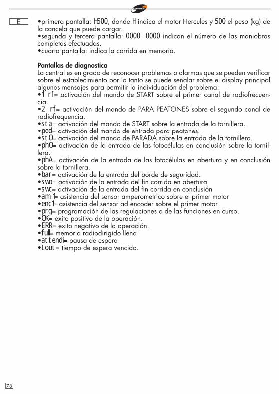
E •primera pantalla: H500, donde H indica el motor Hercules y 500 el peso (kg) de la cancela que puede cargar.•segunda y tercera pantalla: 0000 0000 indican el número de las maniobras completas efectuadas.•cuarta pantalla: indica la corrida en memoria.
Pantallas de diagnosticaLa central es en grado de reconocer problemas o alarmas que se pueden verifi car sobre el establecimiento por lo tanto se puede señalar sobre el display principal algunos mensajes para permitir la individuación del problema:•1 rf= activación del mando de START sobre el primer canal de radiofrecuen-cia.•2 rf= activación del mando de PARA PEATONES sobre el segundo canal de radiofrequencia.•sta= activación del mando de START sobre la entrada de la tornillera.•ped= activación del mando de entrada para peatones.•stO= activación del mando de PARADA sobre la entrada de la tornillera.•phO= activación de la entrada de las fotocélulas en conclusión sobre la tornil-lera.•phA= activación de la entrada de las fotocélulas en abertura y en conclusión sobre la tornillera.•bar= activación de la entrada del borde de seguridad.•swo= activación de la entrada del fi n corrida en abertura•swc= activación de la entrada del fi n corrida en conclusión•am 1= asistencia del sensor amperometrico sobre el primer motor•enc1= asistencia del sensor ad encoder sobre el primer motor•prg= programación de las regulaciones o de las funciones en curso.•OK= exito positivo de la operación.•ERR= exito negativo de la operación.•full= memoria radiodirigido llena•attendi= pausa de espera•tout= tiempo de espera vencido.
78
E
Datos Técnicos•Alimentación de la automación: 230V - 50/60Hz.•Fusible de protección primario transformador: F5A/230V.•Fusible de protección de la salida accesorios 24V: T1A•Recibidor integrado (433Mhz): llevada máxima 76 código radio.•Temperadura de funcionamiento: -20° +55°•Potencia nominal máxima del motor: 500W•Potencia máxima de la salida relampagueante: 40W•Potencia máxima de la salida espía cancela abierta (SCA): 5W
F.A.Q. - Las preguntas más frecuentemente hechas
¿Porqué escoger un transmetidor rolling code más que uno a código fi jo?Los transmetidores rolling code se tiene que considerar más seguros en cuanto no son clonables y tienen más de 200 millones de combinaciones que cambian a cada tran-smisión. Los transmetidores a código fi jo, en vez, dispoen de 1024 combinaciones de códigos que no cambian a cada transmisión.
La central no reconoce el transmetidor. ¿Porqué?Acertarse de utilizar central y transmetidores del mismo tipo. En la primera pantalla principal se puede verifi car el tipo de recibidor utilizado desde la central y eventual-mente cambiarlo impostando el parametro cf.
79
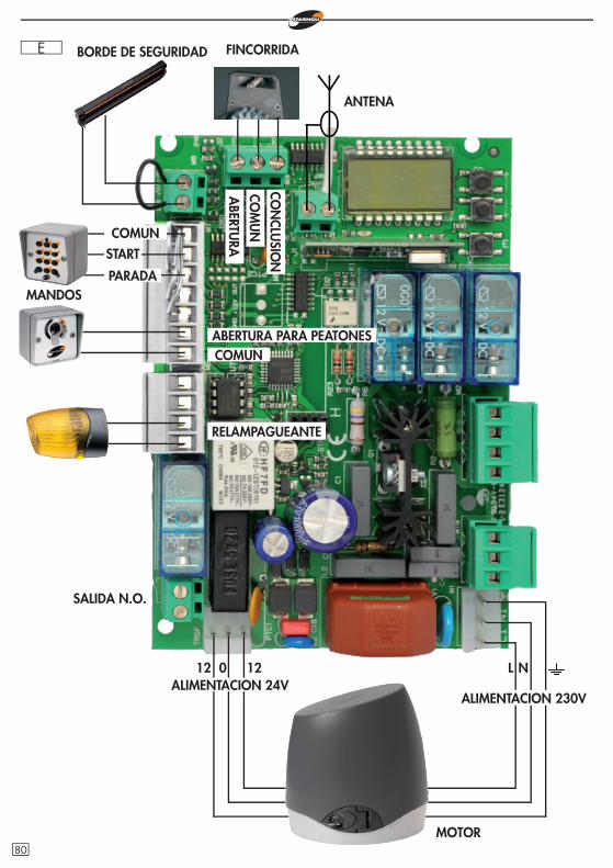
E BORDE DE SEGURIDAD
MANDOS
COMUNABERTURA PARA PEATONES
RELAMPAGUEANTE
012 12 L N
FINCORRIDA
MOTOR
COMUN
PARADA
START
CON
CLUSIO
NCO
MU
NA
BERTURA
ANTENA
ALIMENTACION 24VALIMENTACION 230V
SALIDA N.O.
80
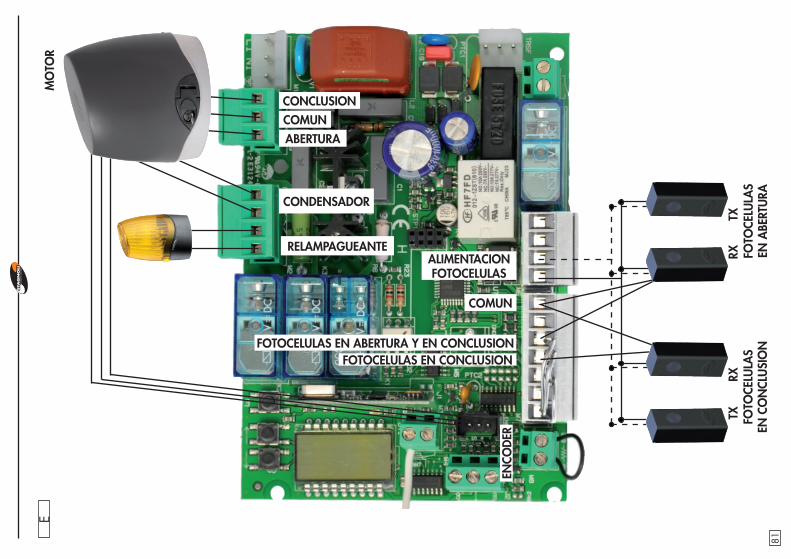
E
ENCO
DER
MO
TOR
RELAMPAGUEANTE
CONDENSADOR
CONCLUSIONCOMUNABERTURA
FOTO
CELU
LAS
EN C
ON
CLU
SIO
NFO
TOCE
LULA
S EN
ABE
RTU
RA
TXRX
RXTX
ALIMENTACION FOTOCELULAS
COMUN
FOTOCELULAS EN CONCLUSIONFOTOCELULAS EN ABERTURA Y EN CONCLUSION
81

82

83
I
Stagnoli T.G. srlVia Mantova, trav. I, 105A/B
+39.0309139511 [email protected]
X61A759
Mr. Francesco AlbieroThe President
GB
F
D
E
Dichiarazione di conformitàIl sottoscritto Francesco Albiero, dichiara che il prodotto H230 è conforme a tutte le norme tecniche relative al prodotto entro il campo di applicabilità delle Diret-tive Comunitarie.
Declaration of ConformityThe undersigned, Francesco Albiero, declares that the product H230 is in com-pliance with the technical requirements of the European Directives.
Déclaration de conformitéLe soussigné, Francesco Albiero, déclare que le produit H230 est conforme à to-utes les normes techniques relatives au produit dans le champ d’applicabilité des Directives Communautaires.
KonformitätserklärungDer Unterzeichnete, Francesco Albiero, erklärt, dass der Produkt H230 mit den technischen Erfordernissen der EG Richtilienen übereinstimmt.
Declaración de conformidadEl suscrito Sr. Francesco Albiero declara que el producto H230 es con-forme a los criterios técnicos requeridos por las directivas comunitarias.
2004/108/CE EMC2006/95/CE LVD99/05/CE R&TTE
Costruttore e rappresentante autorizzato:Authorized producer and representative:
Constructeur et représentant autorisé:Genehmigter Hersteller und Vertreter:
Fabricante y representante autorizado:
Stagnoli T.G. srlVia Mantova, trav 1, 105 A/B
25017 Lonato (BS)Italy
tel: +39.0309139511fax: +39.0309139580