ELETTROPOMPE - HSP Partners
35
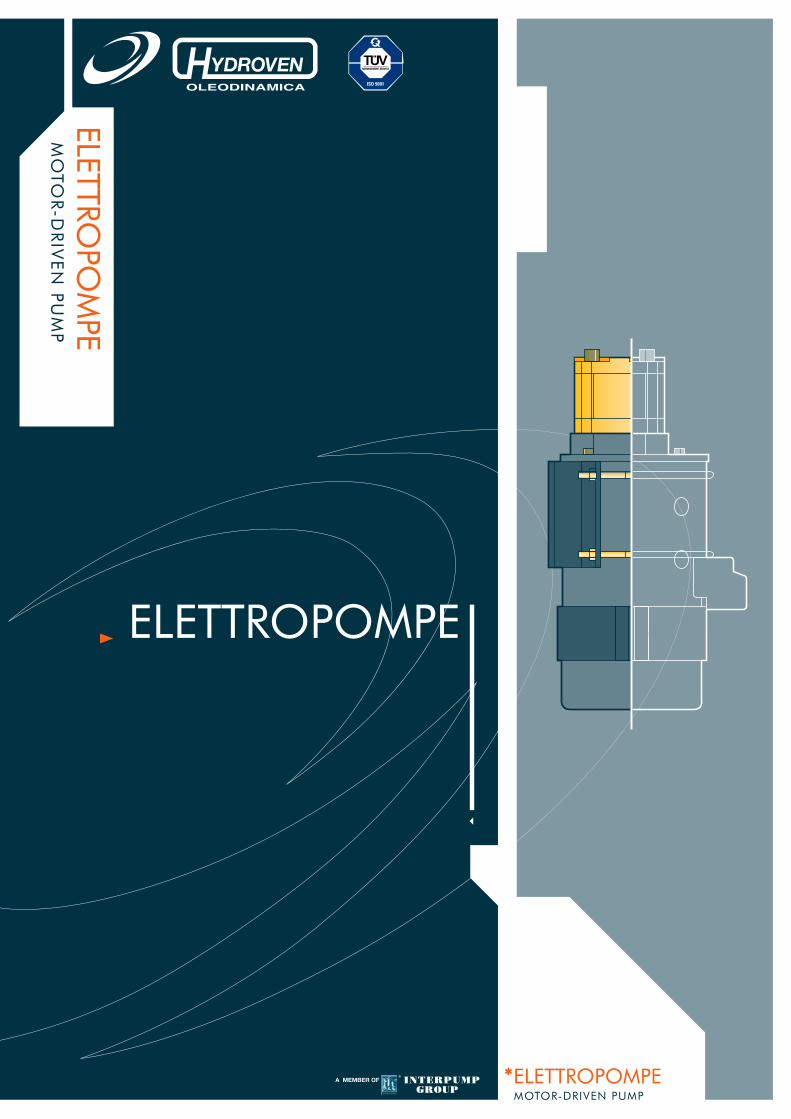
ELETTROPOMPE MOTOR-DRIVEN PUMP *ELETTROPOMPE MOTOR-DRIVEN PUMP ELETTROPOMPE
Transcript of ELETTROPOMPE - HSP Partners
ELETTROPO
MPE
MO
TOR-D
RIV
EN
PUM
P
*ELETTROPOMPEMOTOR-DRIVEN PUMP
ELETTROPOMPE

INDICE INDEX
www.hydroven.com e-mail: [email protected]
4 ISTRUZIONI D’USOMAINTENANCE MANUAL
5 TRASPORTO, MOVIMENTAZIONE, IMMAGAZZINAGGIOTRANSPORT, HANDLING, STORAGE
6 MESSA IN SERVIZIOINSTALLATION
8 INDICAZIONI PER LA MANUTENZIONEMAINTENACE INFORMATIONS
26 ELETTROPOMPA CON MOTORE 24 V - 4.5 kW - 150 VENTILATOFAN MOTOR PUMP UNIT 24 V - 4.5 kW - 150
28 ELETTROPOMPA CON MOTORE 24 V - 4.5 kW - 170 VENTILATOFAN MOTOR PUMP UNIT 24 V - 4.5 kW - 170
24 ELETTROPOMPA CON MOTORE 24 V - 3 kW - 150 VENTILATOFAN MOTOR PUMP UNIT 24 V - 3 kW - 150
10 ELETTROPOMPA CON MOTORE 12 V - 1.6 kW - 114MOTOR PUMP UNIT 12 V - 1.6 kW - 114
18 ELETTROPOMPA CON MOTORE 24 V - 2.2 kW - 114MOTOR PUMP UNIT 24V - 2.2 kW - 114
14 ELETTROPOMPA CON MOTORE 12 V - 1.5 kW - 114 VENTILATOFAN MOTOR PUMP UNIT 12 V - 1.5 kW - 114
16 ELETTROPOMPA CON MOTORE 24V - 2 kW - 114MOTOR PUMP UNIT 24 V - 2 kW - 114
12 ELETTROPOMPA CON MOTORE 12 V - 1.8 kW - 114MOTOR PUMP UNIT 12 V - 1.8 kW - 114
20 ELETTROPOMPA CON MOTORE 24 V - 2 kW - 114 VENTILATOFAN MOTOR PUMP UNIT 24 V - 2 kW - 114
22 ELETTROPOMPA CON MOTORE 24 V - 3 kW - 125 VENTILATOFAN MOTOR PUMP UNIT 24 V - 3 kW - 125
30 RACCORDI A FLANGIA RFELBOW COUPLING RF
31 TELERUTTORI DI AVVIAMENTOSTARTING RELAY
32 SUPPORTO MOTORE VENTILATO - 150 - 170FAN MOTOR SUPPORT BRACKET - 150 - 170
33 SUPPORTO MOTORE VENTILATO - SUPPORTO PER MOTORE 24 V, 3 KW, 125KIT COMPLETOFAN MOTOR SUPPORT BRACKET - MOTOR 24 V, 3 KW, 125 SUPPORT BRACKETCOMPLETE SUPPORT BRACKET UNIT
N.B. Tutte le elettropompe riportate nel catalogo sono provviste di termocoppia eteleruttore (anche dove non riportato nel disegno).
N.B. The motor pump units provided of thermocouple and starter (even if thedrawing doesn’t report).
ELETTROPOMPE
.4
2006
info
@hy
drov
en.c
omw
ww
.hyd
rove
n.c
om
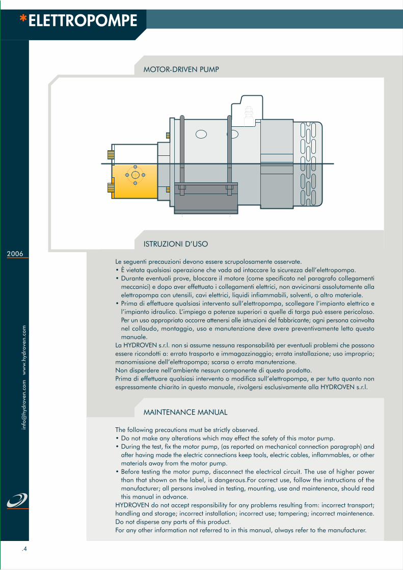
MOTOR-DRIVEN PUMP
ISTRUZIONI D’USO
Le seguenti precauzioni devono essere scrupolosamente osservate.• È vietata qualsiasi operazione che vada ad intaccare la sicurezza dell’elettropompa.• Durante eventuali prove, bloccare il motore (come specificato nel paragrafo collegamenti
meccanici) e dopo aver effettuato i collegamenti elettrici, non avvicinarsi assolutamente allaelettropompa con utensili, cavi elettrici, liquidi infiammabili, solventi, o altro materiale.
• Prima di effettuare qualsiasi intervento sull’elettropompa, scollegare l’impianto elettrico el’impianto idraulico. L’impiego a potenze superiori a quelle di targa può essere pericoloso.Per un uso appropriato occorre attenersi alle istruzioni del fabbricante; ogni persona coinvoltanel collaudo, montaggio, uso e manutenzione deve avere preventivamente letto questomanuale.
La HYDROVEN s.r.l. non si assume nessuna responsabilità per eventuali problemi che possonoessere ricondotti a: errato trasporto e immagazzinaggio; errata installazione; uso improprio;manomissione dell’elettropompa; scarsa o errata manutenzione.Non disperdere nell’ambiente nessun componente di questo prodotto.Prima di effettuare qualsiasi intervento o modifica sull’elettropompa, e per tutto quanto nonespressamente chiarito in questo manuale, rivolgersi esclusivamente alla HYDROVEN s.r.l.
MAINTENANCE MANUAL
The following precautions must be strictly observed.• Do not make any alterations which may effect the safety of this motor pump.• During the test, fix the motor pump, (as reported on mechanical connection paragraph) and
after having made the electric connections keep tools, electric cables, inflammables, or othermaterials away from the motor pump.
• Before testing the motor pump, disconnect the electrical circuit. The use of higher powerthan that shown on the label, is dangerous.For correct use, follow the instructions of themanufacturer; all persons involved in testing, mounting, use and maintenence, should readthis manual in advance.
HYDROVEN do not accept responsibility for any problems resulting from: incorrect transport;handling and storage; incorrect installation; incorrect use; tampering; incorrect maintenence.Do not disperse any parts of this product.For any other information not referred to in this manual, always refer to the manufacturer.

.5
TRASPORTO E MOVIMENTAZIONE. In caso di trasporto, prevedere un imballo di adeguataresistenza impiegando un cartone rigido o una cassetta di legno imbottita di materialeantiurto. Assicurarsi che corpi estranei come polistirolo, punti metallici, etc... non possanoentrare all’interno del motore.Proteggere adeguatamente, mediante imbottiture o coperchi in plastica, gli alberi in uscitao la pompa A, la zona dei morsetti B e la parte posteriore C.Il motore deve sempre essere trasportato e immagazzinato in posizione orizzontale.
IMMAGAZZINAGGIO. Qualora il prodotto non venga posto subito in esercizio, deve essereconservato in ambiente asciutto, pulito e privo di vibrazioni in quanto si potrebberodanneggiare le parti elettriche, meccaniche e le sedi dei cuscinetti.Per lunghi periodi di giacenza è opportuno sollevare le spazzole dal collettore ed, inoltreruotare periodicamente l’albero motore (una volta al mese).Per giacenze superiori alle due settimane, apporre sugli alberi e sulle flange di accoppiamentovernici o grassi antiossidanti.
TRASPORTO E MOVIMENTAZIONE, IMMAGAZZINAGGIO
TRANSPORT AND HANDLING. For transportation, use adeguate packing, in a carton orwooden case. Protect the motor to ensure that polystyrene, paper, metallic staples or otherforeign bodies can not enter into the motor. Always ensure that the output drive shaft A,the terminals B, and the non drive cover C, are adequately protected.The electrohydraulic pump must be packed, transported and stored in a horizontal position.
STORAGE. If the electrohydraulic pump is not required for immediate use, it must be storedin a clean area humidity and vibration free, to avoid damage to the bearings and electricalcomponents.For long storage periods, the brushes must be raised from the commutator, and the motorshaft must be turned regularly (once a mont). For storage over two weeks, apply a coatof paint or antioxiding grease to the motor shaft and driving flanges.
TRANSPORT AND HANDLING, STORAGE
Schema trasporto e movimentazione - Transport and handling diagram
A B C

ELETTROPOMPE
.6
2006
info
@hy
drov
en.c
omw
ww
.hyd
rove
n.c
om
COLLEGAMENTI MECCANICI. Tutte le elettropompe possono essere montate in posizione orizzontale o verticale il fissaggioal telaio deve avvenire mediante una staffa che non trasmetta vibrazioni all’elettropompa, e posizionata nella zona liberadella carcassa motore. Non utilizzare, per il fissaggio, la pompa, la morsettiera il supporto ventola, etc... Si consiglial’utilizzo di una staffa HYDROVEN. Il vano ove verrà posizionata l’elettropompa deve consentire una portata d’ariasufficiente e permettere una facile accessibilità per le operazioni di manutenzione.
COLLEGAMENTI ELETTRICI. I cavi di collegamento devono avere una sezione tale che la densità di corrente non superi ilvalore di 3 A/mm2. Collegare i terminali dei cavi al morsetti fra dado e controdado, bloccando con la chiave il dado inferiore,e serrando con l’altra il dado superiore facendo attenzione a non far ruotare i perni centrali. Questi infatti sono collegatialle bobine di campo ed una loro rotazione potrebbe causare un’interruzione nei collegamenti elettrici. Le elettropompe coneccitazione in serie, composta e parallelo, vengono fornite con un unico senso di rotazione a prescindere dall’ordine concui vengono collegati i cavi di alimentazione. Salvo diversa richiesta all’ordine tutte le elettropompe fornite dalla HYDROVENhanno pompa con rotazione sinistra e albero motore con rotazione destra. In ogni caso verificare sempre la rotazione dellapompa, controllando la targa di identificazione. Nelle elettropompe a magneti permanenti, invertendo i cavi di alimentazionesi inverte il senso di rotazione; per questo è importante effettuare il collegamento dei cavi come specificato sulla morsettiera.In caso di collegamento errato, fermare immediatamente l’elettropompa, invertire i cavi e controllare che l’anello di tenutaalloggiato fra pompa e motore non abbia subito danni. Proteggere sempre tutti i morsetti con le apposite protezioni. Sel’elettropompa viene fornita completa di teleruttore di avviamento, il collegamento deve avvenire come raffigurato nell’esempioriportato qui sotto. Nel caso in cui l’elettropompa venga montata su una macchina e comandata da un controllo elettronico,occorre sempre accertarsi della compatibilità fra il tipo di eccitazione dell’elettropompa ed il controllo stesso.
COLLEGAMENTI OLEODINAMICI. Le pompe fornite sono del tipo a ingranaggi esterni a bassa rumorosità. Le caratteristicheda rispettare scrupolosamente sono: temperatura ambiente da -5 °C a +60 °C; temperatura dell’olio da -10 °C a +80°C (per temperature superiori occorrono guarnizioni speciali); viscosità dell’olio da 12 a 80 mm2/s filtraggio <25 m.Per un corretto funzionamento hanno notevole importanza sia il tubo di aspirazione che il tubo di mandata. Prevedereun tubo di aspirazione tale da garantire una velocità dell’olio V=0,6-1,2 m/s. e un tubo di mandata per avere V=6-8m/s. Evitare inoltre forti dislivelli fra pompa e serbatoio, lunghi percorsi, e accidentalità come curve, forti variazioni didiametro etc… Nella versione standard le pompe non possono funzionare con pressione in aspirazione. Accertarsi chesia sempre presente nell’impianto oleodinamico la valvola di massima pressione funzionante ed opportunamente tarata.
MESSA IN SERVIZIO
Carcassa motore - Motor case
Senso di rotazione pompa e albero motore - Motor and pump shaft rotation
Kit completo - Complete support bracket unit
Rotazione antiorariaAnti clockwise
Rotazione orariaClockwise rotation

.7
INSTALLATION
MECCANICAL INSTALLATION. All the electrohydraulic pumps can be mounted in horizontal or vertical positions. Thefixing on the frame, should be made with a steel bracket that does not transmit vibrations to the motor pump. Fastenthe bracket to the area of the motor case. Do not use the terminals, the pump, the fan cover etc. for fixing the motorpump. We recomand using the foot mounting bracket made by HYDROVEN. The motor pump should be mountedin area large enough to allow sufficient ventilation and ease of maintenence
ELECTRIC CONNECTIONS. The connecting cable section must be sufficient to ensure that the current density does notexceed 3 A/mm2. The cable should be connected between the two nuts. It is essential that the terminal posts are lockedwhen tightening the nuts, as the posts are connected directly to the motor field windings. Any disturbance of the postscould result in a failure of the connection to the field windings. Electrohydraulic pumps fitted with motor windings ofthe types, series wound, compound wound and shunt wound, have only one rotational direction, whichever way theelectrical connections are made. Unless otherwise specified, HYDROVEN pumps have an anti-clockwise rotation, withthe motor drive shaft clockwise. In any case always check the rotation shown on the rating plate. For pumps fittedwith permanent magnet motors, it is essential that the electrical connections are made strictly as per the polarity ofthe terminals. In the event of these connections being interposed, and the motor runs in the wrong direction, it shouldbe stopped immediately, the connections should be re-made and the oil seal fitted between motor and pump shouldbe checked to ensure that the seating is still correct. The terminals should always be protected with the covers. If theelectrohydraulic pumps are supplied with a contactor, make sure that the wiring is made as reported on the belowscheme. If the electrohydraulic pumps are installed on a truck, and are driven by an electronic controller, check alwaysthe compatibility between the motor winding and the type of the controller.
HYDRAULIC CONNECTIONS. The gear pumps supplied are of external gear low noise type. Please ensure the following:the ambient temperature is between -5 °C and +60 °C; the oil temperature is between -10 °C to +80 °C. For highertemperatures special oil seals need to be supplied. The oil viscosity should be from 12 to 80 mm2/s. Oil filtrationshould be <25 m. That for correct operation the suction pipe oil speed should be between V=0,6-1,2 m/s, and thedelivery pipe oil speed should be between V=6-8 m/s. That the difference in height between the oil tank and thepump should be kept to a minimum. The pipe should be as straight as possible, with as few diameter differences,and as short as possible. The pump can not operate if there is pressure at the suction port. Ensure the presence of arelief valve in the hydraulic circuit and that it is in good working condition and adjusted at the right pressure.
.7
Collegamento per pompa fornita con teleruttore - Electric scheme Protezione morsetti - Clamp protection

ELETTROPOMPE
.8
2006
info
@hy
drov
en.c
omw
ww
.hyd
rove
n.c
om
CONTROLLI ALL’AVVIAMENTO. Appena ultimata l’installazione, occorre effettuare una serie di controlli.Verificareche tutte le viti siano serrate. Verificare l’isolamento fra morsetti e corpo motore (deve essere >2 MΩ).All’avviamento dell’elettropompa controllare che i collegamenti sia elettrici che idraulici siano stati eseguitiin modo corretto. Verificare che la pompa aspiri dal serbatoio in modo corretto, cioè senza cavitazione. Avolte infatti a causa di un tubo di aspirazione di diametro errato o troppo lungo la pompa non aspira l’oliocorrettamente dando luogo a rumori, bolle d’aria nell’olio e in alcuni casi si può arrivare alla totale assenzadi olio in mandata. Controllare che l’assorbimento di corrente alla massima potenza sia entro i limiti ditarga. Verificare il grado di scintillio delle spazzole sul collettore, questo infatti è molto importante perstabilire una corretta installazione e messa a punto dell’elettropompa.
CONTROLLI PERIODICI. Ogni 500 ore di lavoro verificare. Spazzole: verificarne l’usura, che scorrano beneentro la propria sede, che la superficie di appoggio sul collettore sia regolare. Molle: non devono esserebruciate o danneggiate e devono continuare ad esercitare una pressione uguale e costante sulla spazzola.Collettore: verificare che la superficie sia pulita e regolare, e che non presenti solchi o bruciature.Ogni 1000 ore di lavoro. Cuscinetti: tutti i cuscinetti sono del tipo a doppio schermo e con grasso ad altatemperatura. Verificare quindi che non vi siano perdite di grasso, vibrazioni o rumore. Nel caso di sostituzioneutilizzare sempre cuscinetti dello stesso tipo. Isolamento: verificare, soprattutto in ambienti umidi, chel’isolamento verso massa sia >2 MΩ. Tenute: verificare la perfetta tenuta di tutte le guarnizioni. Viti: verificareche non vi siano viti allentate, in particolare che vi sia un buon serraggio nei collegamenti elettrici.Avvolgimenti: verificare che l’isolamento verso massa sia >2 MΩ. Verificare inoltre che non siano entratinel motore corpi estranei, sporco, e che i fori di ventilazione non siano ostruiti.
MANUTENZIONE E SOSTITUZIONE DELLE POMPE. Le pompe fornite sono del tipo a ingranaggi esterni abassa rumorosità. I tipi maggiormente impiegati sono due e precisamente: gruppo 1 e gruppo 2.Gruppo 1. Per montare la pompa occorre seguire queste istruzioni. Inserire l’anello di tenuta (1), se nonpresente, nell’apposita sede che deve garantire la tenuta di olio tra pompa e motore. Inserire il giunto ditrascinamento (2). Montare la pompa (3) facendo attenzione di mantenere il giunto nella sua posizionecorretta e ben inserito nella penna dell’albero ed inoltre di non rovinare l’OR alloggiato sul centraggio dellapompa. Il bloccaggio della pompa avviene mediante le viti (4). La coppia di serraggio non deve superarei 25 Nm.Gruppo 2. Per montare o sostituire la pompa si procede come nel caso precedente. In questo caso le vitidi fissaggio sono quattro, e la coppia di serraggio non deve superare i 50 Nm.
INDICAZIONI PER LA MANUTENZIONE
Scintillio correttoCorrect sparking
Scintillio non correttoNot correct sparking
.9
MAINTENACE INFORMATIONS
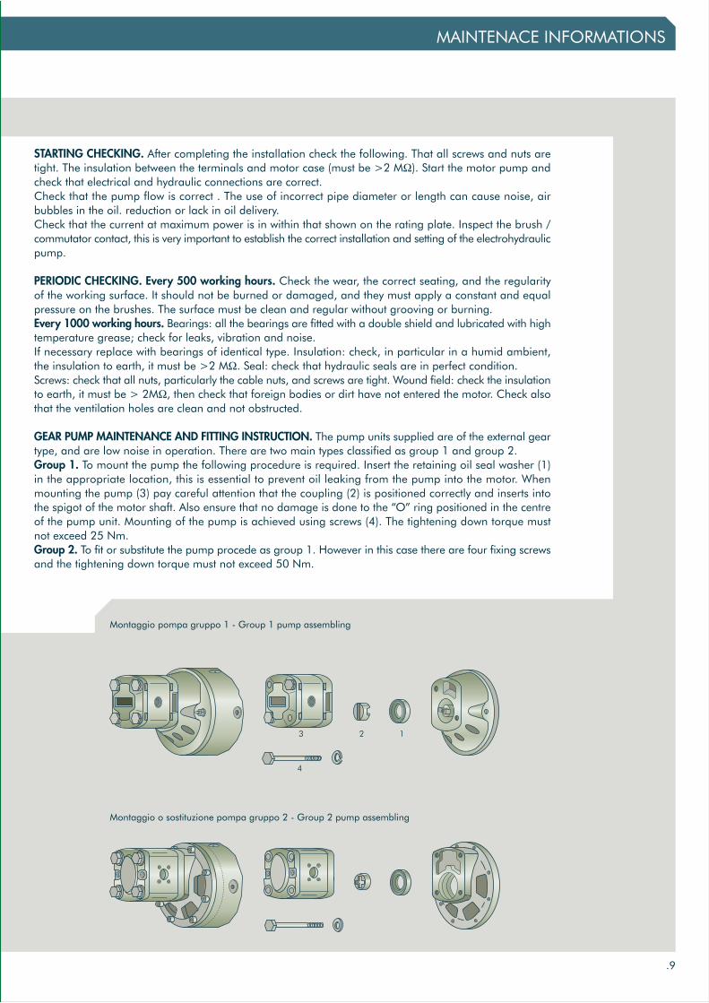
STARTING CHECKING. After completing the installation check the following. That all screws and nuts aretight. The insulation between the terminals and motor case (must be >2 MΩ). Start the motor pump andcheck that electrical and hydraulic connections are correct.Check that the pump flow is correct . The use of incorrect pipe diameter or length can cause noise, airbubbles in the oil. reduction or lack in oil delivery.Check that the current at maximum power is in within that shown on the rating plate. Inspect the brush /commutator contact, this is very important to establish the correct installation and setting of the electrohydraulicpump.
PERIODIC CHECKING. Every 500 working hours. Check the wear, the correct seating, and the regularityof the working surface. It should not be burned or damaged, and they must apply a constant and equalpressure on the brushes. The surface must be clean and regular without grooving or burning.Every 1000 working hours. Bearings: all the bearings are fitted with a double shield and lubricated with hightemperature grease; check for leaks, vibration and noise.If necessary replace with bearings of identical type. Insulation: check, in particular in a humid ambient,the insulation to earth, it must be >2 MΩ. Seal: check that hydraulic seals are in perfect condition.Screws: check that all nuts, particularly the cable nuts, and screws are tight. Wound field: check the insulationto earth, it must be > 2MΩ, then check that foreign bodies or dirt have not entered the motor. Check alsothat the ventilation holes are clean and not obstructed.
GEAR PUMP MAINTENANCE AND FITTING INSTRUCTION. The pump units supplied are of the external geartype, and are low noise in operation. There are two main types classified as group 1 and group 2.Group 1. To mount the pump the following procedure is required. Insert the retaining oil seal washer (1)in the appropriate location, this is essential to prevent oil leaking from the pump into the motor. Whenmounting the pump (3) pay careful attention that the coupling (2) is positioned correctly and inserts intothe spigot of the motor shaft. Also ensure that no damage is done to the “O” ring positioned in the centreof the pump unit. Mounting of the pump is achieved using screws (4). The tightening down torque mustnot exceed 25 Nm.Group 2. To fit or substitute the pump procede as group 1. However in this case there are four fixing screwsand the tightening down torque must not exceed 50 Nm.
Montaggio pompa gruppo 1 - Group 1 pump assembling
Montaggio o sostituzione pompa gruppo 2 - Group 2 pump assembling
3 2 1
4

ELETTROPOMPA CON MOTORE 12 V - 1.6 kW - 114
.10
2006
info
@hy
drov
en.c
omw
ww
.hyd
rove
n.c
om
MOTOR PUMP UNIT 12 V - 1.6 kW - 114
1.6
1.6
1.6
1.6
1.6
POTENZANOMINALE
RATED POWERkW
12
12
12
12
12
TENSIONENOMINALE
RATED VOLTAGEvolt
I 200 A
I 200 A
I 200 A
I 200 A
I 200 A
CORRENTENOMINALE
RATED CURRENT
2600
2600
2600
2600
2600
VELOCITÀNOMINALERATED SPEED
S2=3min
S2=3min
S2=3min
S2=3min
S2=3min
TEMPI DIESERCIZIO
OPERATION MODErpm
IP 54
IP 54
IP 54
IP 54
IP 54
PROTEZIONEPROTECTION
623A1600HAB0
623A1601HAB0
623A1602HAB0
623A1603HAB0
623A1604HAB0
CODICECODE
S3-7,5%
S3-7,5%
S3-7,5%
S3-7,5%
S3-7,5%
A2E2 D1E1
M
173.50
15±0.0000
A
B
15
F
E
57
.5(2
.26
)
d
37
M8
20°
40°30°
54.5
27
sw13
53
11
4
Ø112
82(3.23)
10(.39)
82
53.5

.11
DIMENSIONE DIMENSION
SX
SX
SX
SX
SX
1.2
1.7
2.5
3.5
4.3
82.5
84.5
88
92
96
38.5
39.5
41
43.5
45
30
30
30
30
30
210
210
210
210
210
M6
M6
M6
M6
M6
250
250
250
230
230
12
12
12
12
12
280
280
280
250
250
ROTAZIONEROTATION A B E F P3P1d P2
ENTRATA - USCITA INLET - OUTLET PRESSIONE PRESSURECILINDRATA
DISPLACEMENTcm3 mm mm
AP100/1.2
AP100/1.7
AP100/2.5
AP100/3.5
AP100/4.3
TIPO POMPAPUMP TYPE
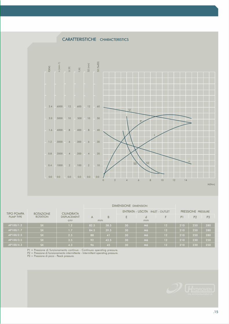
CARATTERISTICHE CHARACTERISTICSCARATTERISTICHE CHARACTERISTICS
0 2 4 6 8 10 12 14
2210021000
4420042000
6630063000
8840084000
10500105000
600146000
U (V
)
I (A
)
S2 (m
in)
S3 (‰
ED)
0.0
12
0.0 0.0 0.0 0.0
10
12
0.5
1.0
1.5
0.0
P(K
W)
I
n
U
S3
M(Nm)
n (R
PM)
P
2.0
2.5
3.0
S2
P1 = Pressione di funzionamento continua - Continuos operating pressure.P2 = Pressione di funzionamento intermittente - Intermittent operating pressure.P3 = Pressione di picco - Peack pressure.
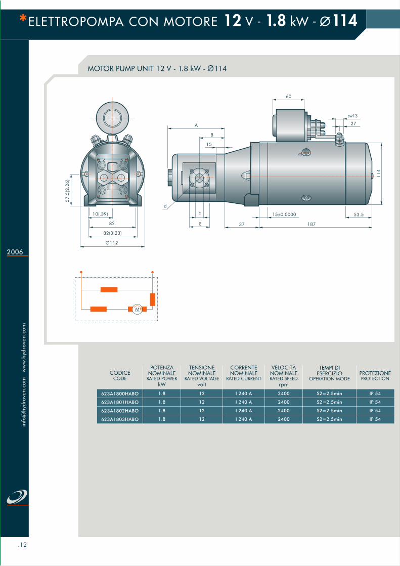
ELETTROPOMPA CON MOTORE 12 V - 1.8 kW - 114
.12
2006
info
@hy
drov
en.c
omw
ww
.hyd
rove
n.c
om
MOTOR PUMP UNIT 12 V - 1.8 kW - 114
1.8
1.8
1.8
1.8
POTENZANOMINALE
RATED POWERkW
12
12
12
12
TENSIONENOMINALE
RATED VOLTAGEvolt
I 240 A
I 240 A
I 240 A
I 240 A
CORRENTENOMINALE
RATED CURRENT
2400
2400
2400
2400
VELOCITÀNOMINALERATED SPEED
S2=2.5min
S2=2.5min
S2=2.5min
S2=2.5min
TEMPI DIESERCIZIO
OPERATION MODErpm
IP 54
IP 54
IP 54
IP 54
PROTEZIONEPROTECTION
623A1800HABO
623A1801HABO
623A1802HABO
623A1803HABO
CODICECODE
57
.5(2
.26
)
Ø112
82(3.23)
10(.39)
82 187
15±0.0000
A
B
15
F
E
d
37
27
sw13
60
11
4
53.5
M

DIMENSIONE DIMENSION
SX
SX
SX
SX
1.2
1.7
2.5
3.5
82.5
84.5
88
92
38.5
39.5
41
43.5
30
30
30
30
210
210
210
210
M6
M6
M6
M6
250
250
250
230
12
12
12
12
280
280
280
250
ROTAZIONEROTATION A B E F P3P1d P2
ENTRATA - USCITA INLET - OUTLET PRESSIONE PRESSURECILINDRATA
DISPLACEMENTcm3 mm mm
AP100/1.2
AP100/1.7
AP100/2.5
AP100/3.5
.13
CARATTERISTICHE CHARACTERISTICS
S2
50 100 150 200 250
10002.50.5202.5
20005.01.0405.0
30007.51.5607.5
40002.08010.0
610012.5
η (%
)
U (V
)
P (k
W)
M (N
.M)
n (r
-min
)
0.0
5000
0.0 0.0 0.0 0.0
η
P
U
10.0
12.5
S2 (m
in)
S3 (5
min
-ED
)
6 35%
30%
3
5
4 25%
20%
2 15%
1 10%
0 5%
7 40%
(A)
DUTY RATING
n
M
S3
8 45%
P1 = Pressione di funzionamento continua - Continuos operating pressure.P2 = Pressione di funzionamento intermittente - Intermittent operating pressure.P3 = Pressione di picco - Peack pressure.
TIPO POMPAPUMP TYPE
300

ELETTROPOMPA CON MOTORE 12 V - 1.5 kW - 114
.14
2006
info
@hy
drov
en.c
omw
ww
.hyd
rove
n.c
om
FAN MOTOR PUMP UNIT 12 V - 1.5 kW - 114
211.5±1
15±0.2
A
B
15
F
E
57
.5(2
.26
)
d
37
10
sw13
11
4
Ø112(4.41)
82(3.23)
10(.39)
82
max47
1.5
1.5
1.5
1.5
1.5
POTENZANOMINALE
RATED POWERkW
12
12
12
12
12
TENSIONENOMINALE
RATED VOLTAGEvolt
I 190 A
I 190 A
I 190 A
I 190 A
I 190 A
CORRENTENOMINALE
RATED CURRENT
2300
2300
2300
2300
2300
VELOCITÀNOMINALERATED SPEED
S2=4min
S2=4min
S2=4min
S2=4min
S2=4min
TEMPI DIESERCIZIO
OPERATION MODErpm
IP 23
IP 23
IP 23
IP 23
IP 23
PROTEZIONEPROTECTION
623A1500HAB2
623A1501HAB2
623A1502HAB1
623A1503HAB1
623A1504HAB1
CODICECODE
S3-10%
S3-10%
S3-10%
S3-10%
S3-10%
A2E2D1E1
M
VENTILATO
.15
DIMENSIONE DIMENSION
SX
SX
SX
SX
SX
1.2
1.7
2.5
3.5
4.3
82.5
84.5
88
92
96
38.5
39.5
41
43.5
45
30
30
30
30
30
210
210
210
210
210
M6
M6
M6
M6
M6
250
250
250
230
230
12
12
12
12
12
280
280
280
250
250
TIPO POMPAPUMP TYPE A B E F P3P1d P2
ENTRATA - USCITA INLET - OUTLET PRESSIONE PRESSURECILINDRATA
DISPLACEMENTcm3 mm mm
AP100/1.2
AP100/1.7
AP100/2.5
AP100/3.5
AP100/4.3
ROTAZIONEROTATION
CARATTERISTICHE CHARACTERISTICSCARATTERISTICHE CHARACTERISTICS
0 2 4 6 8 10 12 14
10210021000
20420042000
30630063000
40840084000
50500105000
600126000
U (V
)
I (A
)
S2 (m
in)
S3 (‰
ED)
0.0
60
0.0 0.0 0.0 0.0
10
12
0.4
0.8
1.2
0.0
P(K
W)
I
n
U
S3
M(Nm)
n (m
in-1
)
P
1.6
2.0
2.4
S2
P1 = Pressione di funzionamento continua - Continuos operating pressure.P2 = Pressione di funzionamento intermittente - Intermittent operating pressure.P3 = Pressione di picco - Peack pressure.
2
2
2
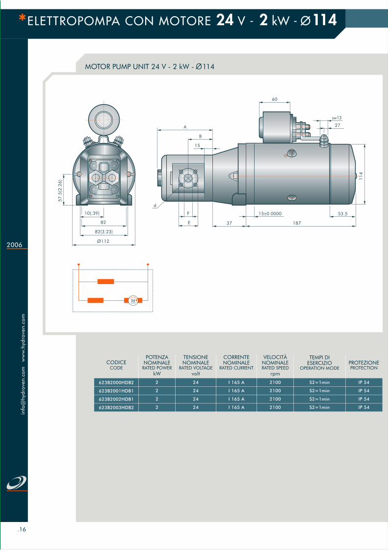
2
POTENZANOMINALE
RATED POWERkW
24
24
24
24
TENSIONENOMINALE
RATED VOLTAGEvolt
I 165 A
I 165 A
I 165 A
I 165 A
CORRENTENOMINALE
RATED CURRENT
2100
2100
2100
2100
VELOCITÀNOMINALERATED SPEED
S2=1min
S2=1min
S2=1min
S2=1min
TEMPI DIESERCIZIO
OPERATION MODErpm
IP 54
IP 54
IP 54
IP 54
PROTEZIONEPROTECTION
623B2000HDB2
623B2001HDB1
623B2002HDB1
623B2003HDB2
CODICECODE
ELETTROPOMPA CON MOTORE 24 V - 2 kW - 114
.16
2006
info
@hy
drov
en.c
omw
ww
.hyd
rove
n.c
om
MOTOR PUMP UNIT 24 V - 2 kW - 1145
7.5
(2.2
6)
Ø112
82(3.23)
10(.39)
82 187
15±0.0000
A
B
15
F
E
d
37
27
sw13
60
11
4
53.5
M
DIMENSIONE DIMENSION
SX
SX
SX
SX
1.2
1.7
2.5
3.5
82.5
84.5
88
92
38.5
39.5
41
43.5
30
30
30
30
210
210
210
210
M6
M6
M6
M6
250
250
250
230
12
12
12
12
280
280
280
250
ROTAZIONEROTATION A B E F P3P1d P2
ENTRATA - USCITA INLET - OUTLET PRESSIONE PRESSURECILINDRATA
DISPLACEMENTcm3 mm mm
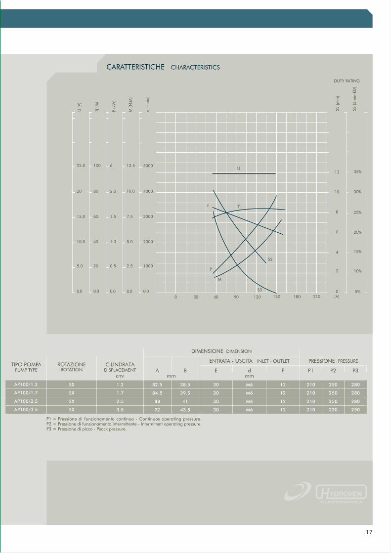
AP100/1.2
AP100/1.7
AP100/2.5
AP100/3.5
P1 = Pressione di funzionamento continua - Continuos operating pressure.P2 = Pressione di funzionamento intermittente - Intermittent operating pressure.P3 = Pressione di picco - Peack pressure.
.17
CARATTERISTICHE CHARACTERISTICS
S2
0 30 60 90 120 150 180
10002.50.5205.0
20005.01.04010.0
30007.51.56015.0
40002.08020
610025.0
η (%
)
U (V
)
P (k
W)
M (N
.M)
n (r
-min
)
0.0210
5000
0.0 0.0 0.0 0.0
η
P
U
10.0
12.5
S2 (m
in)
S3 (5
min
-ED
)
12 35%
30%
6
10
8 25%
20%
4 15%
2 10%
0 5%(A)
DUTY RATING
n
M
S3
TIPO POMPAPUMP TYPE

ELETTROPOMPA CON MOTORE 24 V - 2.2 kW - 114
.18
2006
info
@hy
drov
en.c
omw
ww
.hyd
rove
n.c
om
MOTOR PUMP UNIT 24 V - 2.2 kW - 114
2.2
2.2
2.2
2.2
2.2
POTENZANOMINALE
RATED POWERkW
24
24
24
24
24
TENSIONENOMINALE
RATED VOLTAGEvolt
I 140 A
I 140 A
I 140 A
I 140 A
I 140 A
CORRENTENOMINALE
RATED CURRENT
2600
2600
2600
2600
2600
VELOCITÀNOMINALERATED SPEED
S2=1.2min
S2=1.2min
S2=1.2min
S2=1.2min
S2=1.2min
TEMPI DIESERCIZIO
OPERATION MODErpm
IP 54
IP 54
IP 54
IP 54
IP 54
PROTEZIONEPROTECTION
623B2200HDBO
623B2201HDBO
623B2202HDB1
623B2203HDBO
623B2204HDBO
CODICECODE
S3-4.5%
S3-4.5%
S3-4.5%
S3-4.5%
S3-4.5%
A2E2 D1E1
M
173.50
15±0.0000
A
B
15
F
E
57
.5(2
.26
)
d
37
M8
20°
40°30°
54.5
27
sw13
53
11
4
Ø112
82(3.23)
10(.39)
82
53.5

.19
DIMENSIONE DIMENSION
SX
SX
SX
SX
SX
1.2
1.7
2.5
3.5
4.3
82.5
84.5
88
92
96
38.5
39.5
41
43.5
45
30
30
30
30
30
210
210
210
210
210
M6
M6
M6
M6
M6
250
250
250
230
230
12
12
12
12
12
280
280
280
250
250
TIPO POMPAPUMP TYPE A B E F P3P1d P2
ENTRATA - USCITA INLET - OUTLET PRESSIONE PRESSURECILINDRATA
DISPLACEMENTcm3 mm mm
AP100/1.2
AP100/1.7
AP100/2.5
AP100/3.5
AP100/4.3
ROTAZIONEROTATION
CARATTERISTICHE CHARACTERISTICSCARATTERISTICHE CHARACTERISTICS
0 2 4 6 8 10 12 14
225041000
4410082000
66150123000
88200164000
10250205000
300246000
U (V
)
I (A
)
S2 (m
in)
S3 (‰
ED)
0.0
12
0.0 0.0 0.0 0.0
10
12
0.4
0.8
1.2
0.0
P(K
W)
I
n
U
S2
S3
M(Nm)
n (R
PM)
P
1.6
2.0
2.4
P1 = Pressione di funzionamento continua - Continuos operating pressure.P2 = Pressione di funzionamento intermittente - Intermittent operating pressure.P3 = Pressione di picco - Peack pressure.

ELETTROPOMPA CON MOTORE 24 V - 2 kW - 114
.20
2006
info
@hy
drov
en.c
omw
ww
.hyd
rove
n.c
om
FAN MOTOR PUMP UNIT 24 V - 2 kW - 114
211.5±1
15±0.2
A
B
15
E
F
57
.5(2
.26
)
d
37
10
sw13
11
4
Ø112(4.41)
82(3.23)
10(.39)
82
max47
2
2
2
2
2
POTENZANOMINALE
RATED POWERkW
24
24
24
24
24
TENSIONENOMINALE
RATED VOLTAGEvolt
I 320 A
I 320 A
I 320 A
I 320 A
I 320 A
CORRENTENOMINALE
RATED CURRENT
2200
2200
2200
2200
2200
VELOCITÀNOMINALERATED SPEED
S2=4.5min
S2=4.5min
S2=4.5min
S2=4.5min
S2=4.5min
TEMPI DIESERCIZIO
OPERATION MODErpm
IP 23
IP 23
IP 23
IP 23
IP 23
PROTEZIONEPROTECTION
623B2000KDB3
623B2001HDB2
623B2002HDB3
623B2003HDB4
623B2004HDB4
CODICECODE
S3-10%
S3-10%
S3-10%
S3-10%
S3-10%
VENTILATO
A2E2D1E1
M

DIMENSIONE DIMENSION
SX
SX
SX
SX
SX
1.2
1.7
2.5
3.5
4.3
82.5
84.5
88
92
96
38.5
39.5
41
43.5
45
30
30
30
30
30
210
210
210
210
210
M6
M6
M6
M6
M6
250
250
250
230
230
12
12
12
12
12
280
280
280
250
250
A B E F P3P1d P2
ENTRATA - USCITA INLET - OUTLET PRESSIONE PRESSURECILINDRATA
DISPLACEMENTcm3 mm mm
AP100/1.2
AP100/1.7
AP100/2.5
AP100/3.5
AP100/4.3
ROTAZIONEROTATION
.21
TIPO POMPAPUMP TYPE
CARATTERISTICHE CHARACTERISTICSCARATTERISTICHE CHARACTERISTICS
0 2 4 6 8 10 12 14
20410041000
40820082000
6012300123000
8016400164000
100500205000
600246000
U (V
)
I (A
)
S2 (m
in)
S3 (‰
ED)
0.0 0.0 0.0 0.0 0.0
20
0.8
1.6
2.4
0.0
P(K
W)
I
n
U
S3
S2
M(Nm)
n (m
in-1
)
P
P1 = Pressione di funzionamento continua - Continuos operating pressure.P2 = Pressione di funzionamento intermittente - Intermittent operating pressure.P3 = Pressione di picco - Peack pressure.

ELETTROPOMPA CON MOTORE 24 V - 3 kW - 125
.22
2006
info
@hy
drov
en.c
omw
ww
.hyd
rove
n.c
om
FAN MOTOR PUMP UNIT 24 V - 3 kW - 125
M
A2E2D1E1
TIPO TYPE
10157
CODICE CODE
179D1015700D
A
135
B
194
H
66÷70
I
100
L
13
M
9
VENTILATO
9057
30
14
2
275A
B
dF
E
15
2,5
B
H
A
M12X80
3I
L
M
30
3
3
3
POTENZANOMINALE
RATED POWERkW
24
24
24
TENSIONENOMINALE
RATED VOLTAGEvolt
I 300 A
I 300 A
I 300 A
CORRENTENOMINALE
RATED CURRENT
2600
2600
2600
VELOCITÀNOMINALERATED SPEED
TEMPI DIESERCIZIO
OPERATION MODErpm
IP 20
IP 20
IP 20
PROTEZIONEPROTECTION
S2=6min
S2=6min
S2=6min
S3-16%
S3-16%
S3-16%
623B3004CE01
623B3006CE01
623B3008CE01
CODICESENZA SUPPORTO
CODEWITHOUT SUPPORT
3
3
3
POTENZANOMINALE
RATED POWERkW
24
24
24
TENSIONENOMINALE
RATED VOLTAGEvolt
I 300 A
I 300 A
I 300 A
CORRENTENOMINALE
RATED CURRENT
2600
2600
2600
VELOCITÀNOMINALERATED SPEED
TEMPI DIESERCIZIO
OPERATION MODErpm
IP 20
IP 20
IP 20
PROTEZIONEPROTECTION
S2=6min
S2=6min
S2=6min
S3-16%
S3-16%
S3-16%
623B3004CE02
623B3006CE02
623B3008CE02
CODICECON SUPPORTO
CODEWITH SUPPORT

.23
Per ulteriori dati tecnici consultare il fascicolo “Pompe ad ingranaggi” - To see gear pump file for further tech dates.
DIMENSIONE DIMENSION
SX
SX
SX
4.5
6.3
8.2
90
93
95.9
78
81
83.9
30
30
30
30
30
30
M6
M6
M8
M6
M6
M6
13
13
13
13
13
13
TIPO POMPAPUMP TYPE A B E F FEd d
ENTRATA INLET USCITA OUTLETCILINDRATA
DISPLACEMENTcm3 mm mm mm
PS-2/4.5 EP0
PS-2/6.3 EP0
PS-2/8.2 EP0
ROTAZIONEROTATION
DIMENSIONE DIMENSION
SX
SX
SX
4.5
6.3
8.2
90
93
95.9
78
81
83.9
30
30
30
30
30
30
M6
M6
M8
M6
M6
M6
13
13
13
13
13
13
TIPO POMPAPUMP TYPE A B E F FEd d
ENTRATA INLET USCITA OUTLETCILINDRATA
DISPLACEMENTcm3 mm mm mm
PS-2/4.5 EP0
PS-2/6.3 EP0
PS-2/8.2 EP0
ROTAZIONEROTATION
CARATTERISTICHE CHARACTERISTICSCARATTERISTICHE CHARACTERISTICS
0 2 4 6 8 10 12 14
201510041000
403020082000
6045300123000
8060400164000
100500205000
600246000
η (R
PM)
U (V
)
I (A
)
S2 (m
in)
S3 (‰
ED)
0.016
0.0 0.0 0.0 0.0
75
1.5
3.0
4.5
0.0
P(K
W)
I
n
U
S3S2
M(Nm)24V 3KW
P

ELETTROPOMPA CON MOTORE 24 V - 3 kW - 150
.24
2006
info
@hy
drov
en.c
omw
ww
.hyd
rove
n.c
om
FAN MOTOR PUMP UNIT 24 V - 3 kW - 150
D1 A2
M
VENTILATO
3
3
3
3
3
POTENZANOMINALE
RATED POWERkW
24
24
24
24
24
TENSIONENOMINALE
RATED VOLTAGEvolt
I 174 A
I 174 A
I 174 A
I 174 A
I 174 A
CORRENTENOMINALE
RATED CURRENT
2000
2000
2000
2000
2000
VELOCITÀNOMINALERATED SPEED
S2=15min
S2=15min
S2=15min
S2=15min
S2=15min
TEMPI DIESERCIZIO
OPERATION MODErpm
IP 23
IP 23
IP 23
IP 23
IP 23
PROTEZIONEPROTECTION
623B3104CEHO
623B3106CEHO
623B3108CEHO
623B3111CEHO
623B3114CEHO
CODICECODE
12
09
2
16
0
308A
Ø1
50
F
E
d
B

.25
DIMENSIONE DIMENSION
SX
SX
SX
SX
SX
4.5
6.3
8.2
11.3
14
90
93
95.9
101.1
105.4
78
81
83.9
89.1
93.4
30
30
30
40
40
30
30
30
30
30
M6
M6
M8
M8
M8
M6
M6
M6
M6
M6
13
13
13
19
19
13
13
13
14
14
TIPO POMPAPUMP TYPE A B E F FEd d
ENTRATA INLET USCITA OUTLETCILINDRATA
DISPLACEMENTcm3 mm mm mm
PS-2/4.5 EP0
PS-2/6.3 EP0
PS-2/8.2 EP0
PS-2/11 EP0
PS-2/14 EP0
ROTAZIONEROTATION
Per ulteriori dati tecnici consultare il fascicolo “Pompe ad ingranaggi” - To see gear pump file for further tech dates.
CARATTERISTICHE CHARACTERISTICS
I
0 4 8 12 16 20 24 28 Nm
400401104
800802208
120012033012
160016044016
200055020
66024
η (%
)
U (V
)
P (k
W)
I (A
)
N (m
in-1
)
0.0
2400
2800
3200
770
80
0.0 0.0 0.0 0.0
η
n
U
S24C37aU=24,7-0.0152.I
S2-1
5min
200
28
32 8
240
280
320
P

ELETTROPOMPA CON MOTORE 24 V - 4.5 kW - 150
.26
2006
info
@hy
drov
en.c
omw
ww
.hyd
rove
n.c
om
FAN MOTOR PUMP UNIT 24 V - 4.5 kW - 150
D1 A2
M
4.5
4.5
4.5
4.5
4.5
4.5
4.5
POTENZANOMINALE
RATED POWERkW
24
24
24
24
24
24
24
TENSIONENOMINALE
RATED VOLTAGEvolt
I 268 A
I 268 A
I 268 A
I 268 A
I 268 A
I 268 A
I 268 A
CORRENTENOMINALE
RATED CURRENT
2000
2000
2000
2000
2000
2000
2000
VELOCITÀNOMINALERATED SPEED
S3-12%
S3-12%
S3-12%
S3-12%
S3-12%
S3-12%
S3-12%
TEMPI DIESERCIZIO
OPERATION MODErpm
IP 23
IP 23
IP 23
IP 23
IP 23
IP 23
IP 23
PROTEZIONEPROTECTION
623B4504CFLO
623B4506CFLO
623B4508CFLO
623B4511CFLO
623B4514CFLO
623B4516CFLO
623B4519CFLO
CODICECODE
S2=4,5min
S2=4,5min
S2=4,5min
S2=4,5min
S2=4,5min
S2=4,5min
S2=4,5min
VENTILATO
12
09
2
16
0
308A
Ø1
50
F
E
d
B

.27
DIMENSIONE DIMENSION
SX
SX
SX
SX
SX
SX
SX
4.5
6.3
8.2
11.3
14
16
19
90
93
95.9
101.1
105.4
108.6
113.5
78
81
83.9
89.1
93.4
96.6
101.5
30
30
30
40
40
40
40
30
30
30
30
30
30
30
M6
M6
M8
M8
M8
M8
M8
M6
M6
M6
M6
M6
M6
M6
13
13
13
19
19
19
19
13
13
13
14
14
14
14
TIPO POMPAPUMP TYPE A B E F FEd d
ENTRATA INLET USCITA OUTLETCILINDRATA
DISPLACEMENTcm3 mm mm mm
PS-2/4.5 EP0
PS-2/6.3 EP0
PS-2/8.2 EP0
PS-2/11 EP0
PS-2/14 EP0
PS-2/16 EP0
PS-2/19 EP0
ROTAZIONEROTATION
CARATTERISTICHE CHARACTERISTICS
U
0 5 10 15 20 25 30 35 Nm
10001001104
20002002208
300030033012
400040044016
500055020
66024
η (%
)
U (V
)
P (k
W)
I (A
)
N (m
in-1
)
0.040
6000
7000
8000
770
80
0.0 0.0 0.0 0.0
η
I
P
S24C29U=25-0,012.I
S2-4
.5m
in
500
28
32 8
600
700
800
S3-1
2%
n
Per ulteriori dati tecnici consultare il fascicolo “Pompe ad ingranaggi” - To see gear pump file for further tech dates.

ELETTROPOMPA CON MOTORE 24 V - 4.5 kW - 170
.28
2006
info
@hy
drov
en.c
omw
ww
.hyd
rove
n.c
om
FAN MOTOR PUMP UNIT 24 V - 4.5 kW - 170
D1 A2
M
4.5
4.5
4.5
4.5
4.5
4.5
4.5
POTENZANOMINALE
RATED POWERkW
24
24
24
24
24
24
24
TENSIONENOMINALE
RATED VOLTAGEvolt
I 248 A
I 248 A
I 248 A
I 248 A
I 248 A
I 248 A
I 248 A
CORRENTENOMINALE
RATED CURRENT
2000
2000
2000
2000
2000
2000
2000
VELOCITÀNOMINALERATED SPEED
S3-25%
S3-25%
S3-25%
S3-25%
S3-25%
S3-25%
S3-25%
TEMPI DIESERCIZIO
OPERATION MODErpm
IP 23
IP 23
IP 23
IP 23
IP 23
IP 23
IP 23
PROTEZIONEPROTECTION
623B4504VFNO
623B4506CFNO
623B4508CFNO
623B4511CFNO
623B4514CFNO
623B4516CFNO
623B4519CFNO
CODICECODE
VENTILATO
13
01
10
17
5
348A
Ø1
71
F
E
d
B
.29
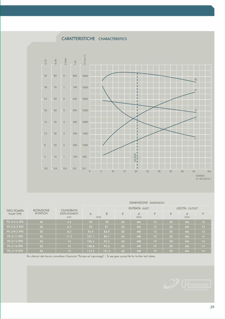
CARATTERISTICHE CHARACTERISTICS
I
0 5 10 15 20 25 30 35 Nm
5001001104
10002002208
150030033012
200040044016
250055020
66024
η (%
)
U (V
)
P (k
W)
I (A
)
N (m
in-1
)
0.040 45
3000
3500
4000
770
80
0.0 0.0 0.0 0.0
η
n
U
S24D04U=25-0,012.1
S3-2
5%
500
28
32 8
600
700
800
DIMENSIONE DIMENSION
SX
SX
SX
SX
SX
SX
SX
4.5
6.3
8.2
11.3
14
16
19
90
93
95.9
101.1
105.4
108.6
113.5
78
81
83.9
89.1
93.4
96.6
101.5
30
30
30
40
40
40
40
30
30
30
30
30
30
30
M6
M6
M8
M8
M8
M8
M8
M6
M6
M6
M6
M6
M6
M6
13
13
13
19
19
19
19
13
13
13
14
14
14
14
ROTAZIONEROTATION A B E F FEd d
ENTRATA INLET USCITA OUTLETCILINDRATA
DISPLACEMENTcm3 mm mm mm
PS-2/4.5 EP0
PS-2/6.3 EP0
PS-2/8.2 EP0
PS-2/11 EP0
PS-2/14 EP0
PS-2/16 EP0
PS-2/19 EP0
TIPO POMPAPUMP TYPE
P
Per ulteriori dati tecnici consultare il fascicolo “Pompe ad ingranaggi” - To see gear pump file for further tech dates.

RACCORDI A FLANGIA RF
.30
2006
info
@hy
drov
en.c
omw
ww
.hyd
rove
n.c
om
ELBOW COUPLING RF
Raccordi acciaio Steel elbow coupling
Raccordi alluminio Steel elbow coupling
Disponibile solo zincato - Available only zinc plated.
TIPOTYPE
RF 223
RF 225
RF 238
A
1/2”
3/4”
3/8”
B
17
22
17
C
27
36
27
D
14
16
14
I
30
40
30
F
6.5
8.5
6.5
CODICECODE
75211B30012A
75211B40013A
75211B30011A
M 6x20
M 8x25
M 6x20
OR
121
132
121
VITISCREWS
TIPOTYPE
RF 197
RF 199
A
1/2”BSP
3/8”BSP
B
30
30
C
16
16
Ø D
6.5
6.5
M(Nm)
10+1
10+1
0-Ring
121
121
CODICECODE
75280B30012A
75280B30011A
G (DIN912)
M6x1x30
M6x1x30
7
070 sh
ØD
B
A
I
FA
B
C
D

.31
TELERUTTORI DI AVVIAMENTO
2006
info
@hy
drov
en.c
omw
ww
.hyd
rove
n.c
om
STARTING RELAY
L
C F
H
L D
L127
CODICE CODE
56252242000K
TIPO TYPE
24V 200A SW180
Ø D44.6
H60.7
C65.5
L86
100
90
86
100
90
CODICE CODE
56252120800K
56252121500K
56252120801H
56252240800K
56252241500K
56252240801H
TIPO TYPE
12V 80A ARD1133
12V 150A RINF. ARD1139
12V 200A
24V 80A ARD1134
24V 150A RINF. ARD1138
24V 200A
Ø D52
52
53
52
52
53
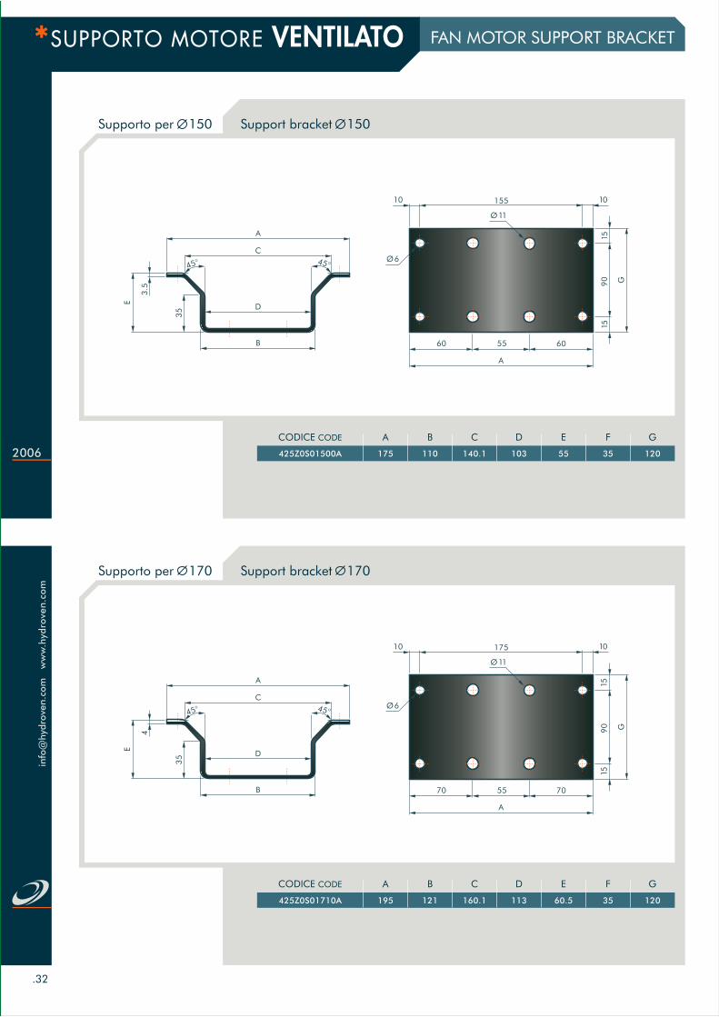
SUPPORTO MOTORE VENTILATO
.32
2006
info
@hy
drov
en.c
omw
ww
.hyd
rove
n.c
om
Supporto per 150 Support bracket 150
Supporto per 170 Support bracket 170
FAN MOTOR SUPPORT BRACKET
G90
15
10
15
7055
A
70
Ø6
17510
Ø11
E
4
35
A
45° 45°
C
D
B
G90
15
10
15
6055
A
60
Ø6
15510
Ø11
3.5
E
35
A
45° 45°
C
D
B
A
195
CODICE CODE
425Z0S01710A
B
121
C
160.1
D
113
E
60.5
F
35
G
120
A
175
CODICE CODE
425Z0S01500A
B
110
C
140.1
D
103
E
55
F
35
G
120

.33
SUPPORTO MOTORE VENTILATO
2006
info
@hy
drov
en.c
omw
ww
.hyd
rove
n.c
om
Supporto per motore 24 V - 3 kW - Ø125
Kit completo Complete support bracket unit
FAN MOTOR SUPPORT BRACKET
H
G
B
HA
M12X80
3
I
L
M
30
TIPO TYPE
10157
CODICE CODE
179D1015700D
A
135
B
194
H
66÷70
I
100
L
13
M
9
DESCRIZIONE DESCRIPTION
Supporto Ø150 con tiranti e dadi M6 R92 L 161x141Support bracket Ø150 composed by guy and nut M6 R92 L 161x141
CODICE CODE
425Z0SK15000
G
120
H
182
Supporto Ø171 con tiranti e dadi M6 R92 L 161x141Support bracket Ø171 composed by guy and nut M6 R92 L 184x155425Z0SK17100 120 194
E
4
35
B
D
C
45° 45°
A
Motor 24 V - 3 kW - Ø125 support bracket

ww
w.h
ydro
ven.
com
e
-mai
l: in
fo@
hydr
oven
.com

ww
w.h
ydro
ven
.co
m
info
@hy
drov
en.c
om
HYDROVEN srl - I-36056 Tezze sul Brenta - Vicenza - Via G. Matteotti 2 - Phone ++39 0424 539381 - Fax ++39 0424 89642 - www.hydroven.com - [email protected]
EP
04
.20
05
C
opie
10
00
Dig
ital S
ervi
ce T
ess
aro
llo
Sil
van
o -
Sta
mpa
Art
i G
rafi
che U
rba
ni