ELECTRONIC CONTROL PANEL FOR FAN COILS WALL-MOUNTED ... · electronic control panel for fan coils...
32
PANNELLO COMANDI ELETTRONICO PER VENTILCONVETTORI INSTALLAZIONE A PARETE ELECTRONIC CONTROL PANEL FOR FAN COILS WALL-MOUNTED INSTALLATION PANNEAU DE COMMANDE ELECTRONIQUE POUR VENTILO-CONVECTEURS INSTALLATION MURALE ELEKTRONISCHE BEDIENTAFEL FÜR GEBLÄSEKONVEKTOREN ZUR WANDMONTAGE TABLERO DE MANDOS ELECTRÓNICO PARA FAN COILS INSTALACIÓN DE PARED MANUALE D’USO E INSTALLAZIONE USE AND INSTALLATION MANUAL MANUEL D'UTILISATION ET D'INSTALLATION BEDIENUNGS- UND INSTALLATIONSANLEITUNG MANUAL DE USO E INSTALACIÓN FMT 20 AW AFMT20AWUJ 0809 63523.21_00
Transcript of ELECTRONIC CONTROL PANEL FOR FAN COILS WALL-MOUNTED ... · electronic control panel for fan coils...
������������ �����������
PANNELLO COMANDI ELETTRONICO PER VENTILCONVETTORIINSTALLAZIONE A PARETE
ELECTRONIC CONTROL PANEL FOR FAN COILSWALL-MOUNTED INSTALLATION
PANNEAU DE COMMANDE ELECTRONIQUE POUR VENTILO-CONVECTEURSINSTALLATION MURALE
ELEKTRONISCHE BEDIENTAFEL FÜR GEBLÄSEKONVEKTORENZUR WANDMONTAGE
TABLERO DE MANDOS ELECTRÓNICO PARA FAN COILSINSTALACIÓN DE PARED
MANUALE D’USO E INSTALLAZIONEU S E A N D I N S TA L L AT I O N M A N UA LMANUEL D'UTILISATION ET D'INSTALLATIONBEDIENUNGS- UND INSTALLATIONSANLEITUNGM A N UA L D E U S O E I N S TA L AC I Ó N
FMT 20 AW
AFMT20AWUJ0809
63523.21_00
3 4 7 28
Caratteristiche Utilizzo Installazione Schemi elettrici
INDICE
8 9 12 28
Characteristics Use Installation Wiring diagrams
INDEX
13 14 17 28
Caractéristiques Utilisation Installation Schémas électriques
TABLE DES MATIÈRES
18 19 22 28
Technische Daten Verwendung Installation Schaltpläne
INDEX
23 24 27 28
Características Uso Instalación Esquemas eléctrico
ÍNDICE
3
Ital
iano
Desideriamo complimentarci con Voi per l’acquisto del pannello comandi con termostato elettro-nico FMT20AW Aermec. Realizzato con materiali di qualità superiore, nel rigoroso rispetto delle normative di sicurezza, “FMT20AW” è di facile utilizzo e vi accompagnerà a lungo nell’uso.
FUNZIONALITA’Il termostato provvede a mantenere nella stanza la temperatura impostata.
Il pannello comandi FMT20AW è dotato delle seguenti funzioni:
- Selezione del modo di funzionamento A u t o m a t i c o , R i s c a l d a m e n t o , Raffrescamento, sola Ventilazione.
- Cambio stagione manuale.- Cambio stagione automatico lato aria.- Controllo di minima temperatura
dell’acqua (riscaldamento) e di massima temperatura dell’acqua (raffrescamento) tramite accessorio SWA, per impianti a 2 tubi senza resistenza. Con tale accessorio la ventilazione è inibita se la temperatura dell’acqua dell’impianto non è adeguata al modo di funzionamento, garantendo così comfort e risparmio energetico.
- Scelta manuale della velocità di ventilazione.
- Scelta automatica della velocità di ventilazione in funzione della temperatura ambiente.
- Ventilazione termostatata. - Ventilazione continua. - Modo di funzionamento in solo
ventilazione.- Visualizza la temperatura impostata.- Visualizza la velocità di ventilazione
impostata.- Visualizza il modo di funzionamento in
riscaldamento.- Visualizza il modo di funzionamento in
raffrescamento.- Visualizza il modo di funzionamento in
automatico.- Al momento dell’accensione avvia
i l vent i lconvet tore mantenendo le impostazioni attive prima dello spegnimento precedente.
- Dopo una mancanza di tensione si riavvia mantenendo le impostazioni attive prima dello spegnimento.
- Sonda della temperatura dell’aria incorporata nel pannello.
- Accessorio sonda esterna SWA ( lunghezza L = 6m). Rileva la temperatura del l ’ar ia ambiente se collegata al connettore (A), automaticamente viene disabilitata la sonda della temperatura dell’aria ambiente incorporata nel pannello. Rileva la temperatura dell’acqua nell’impianto per il consenso alla ventilazione se collegata al connettore (W). Al pannello FMT20AW possono essere collegate contemporaneamente 2 sonde SWA.
VENTILAZIONEControllo della ventilazione a tre velocità, selezionabili manualmente oppure in modo automatico.La velocità di ventilazione si imposta agendo sul pulsante del termostato.Gestione manuale, il ventilatore utilizza dei cicli di On-Off sulla velocità selezionata.Gestione automatica, visualizzazione
, la velocità del ventilatore è gestita dal microprocessore.La gestione automatica della velocità è attiva nei modi raffrescamento, riscaldamento e automatico.Il tempo minimo di funzionamento fra una velocità e l’altra è di 30 secondi.
Modo “SOLO VENTILAZIONE” Il Modo SOLO VENTILAZIONE consente il funzionamento del ventilconvettore anche con l’impianto idraulico spento, nel caso circoli acqua fredda o calda la ventilazione sarà continua e non controllata dal termostato.
VENTILAZIONE CONTINUA L a ve n t i l a z i o n e r i m a n e a t t i va indipendentemente dal raggiungimento della temperatura impostata, il controllo della temperatura viene quindi ottenuto
tramite l’apertura e la chiusura della valvola/valvole dell’acqua inseriti nell’impianto.Non utilizzare questa impostazione negli impianti privi di valvole di inter-cettazione dell’acqua in quanto la venti-lazione sarà continua e non controllata dal termostato.
VENTILAZIONE TERMOSTATATA L a v e n t i l a z i o n e s i s p e g n e automaticamente quando viene raggiunta la temperatura impostata.
Control lo di MINIMA/MASSIMA temperatura acqua (Tw) con accessorio SWA (per ventilazione termostatata)
S e l ’ a c q u a n o n è i d o n e a a l funzionamento sul display lampeggerà lentamente l’icona .
�������� ���������
� �
�����
Tw = Temperatura acquaTa = Temperatura aria
ALLARMI:Se Tw<1°C o Tw>80°C appare l’icona
. Il termostato continua a lavorare senza effettuare il controllo sull’acqua.
Se Ta<1°C o Ta>40°C sul display lampeggerà velocemente l’icona , il termostato chiude la/le valvole e spegne la ventilazione.
CHANGE OVER AUTOMATICO LATO ARIAFunzione a t t iva so lo nel Modo AUTOMATICO .Il controllo consente di stabilire automa-ticamente il modo di funzionamento del ventilconvettore in Riscaldamento oppu-re in Raffrescamento in funzione della temperatura impostata e la temperatura ambiente rilevata dalla sonda aria.
Il termostato di regolazione FMT20AW è un pannello comandi per ventilconvetto-ri, per installazione a parete.Controlla il funzionamento del ventil-convettore in funzione della modalità impostata, della temperatura ambiente per mantenere la temperatura desiderata.I pannelli devono essere montati a parete; vanno utilizzati su impianti a 4 tubi, a 2 tubi e a 2 tubi con resistenza, con la possibilità di collegare due valvole di tipo On - Off per l'intercettazione dell'acqua di alimentazione delle batterie.Ogni pannello può controllare un solo ventilconvettore.Il pannello comandi è composto unica-mente di circuiti elettrici collegati alla
tensione di rete di 230V 50Hz; tutti gli ingressi per le sonde e comandi devono perciò essere corrispondentemente iso-lati per questa tensione.I servocomandi delle valvole devono pure essere dimensionati per 230V 50Hz.FMT20AW può essere installato solo da personale specializzato.Togliere la tensione d’alimentazione prima di iniziare qualsiasi attività di installazione o manutenzione. Il contat-to con i componenti sotto tensione può causare una pericolosa scossa elettrica.
SPECIFICHE TECNICHE:
Alimentazione elettrica: 230V 50Hz (± 10%)
Potenza assorbita: 1.5VARange temperature modificabili: 10°C ÷ 30°C Differenziale: ±0.5°CCondizioni ambientali di funzionamento: 1°C ÷ 60°C con umidità relativa 10% ÷ 90%, senza condensazione.Condizioni ambientali di stoccaggio: -18°C ÷ 60°C con umidità relativa 10% ÷ 90%, senza condensazione.Materiale: ABS UL94 V0Colore: RAL 9016Soddisfa:direttiva LVD 2006/95/CE(EN 60730-1, EN 60730-2-9, EN 60335-1) compatibilità elettromagnetica 2004/108/CE (EN 55011, 55022, 55014) ITS UL873.
Ventilazione Ventilazione
Raffrescamento Riscaldamento
4
Ital
iano UTILIZZO
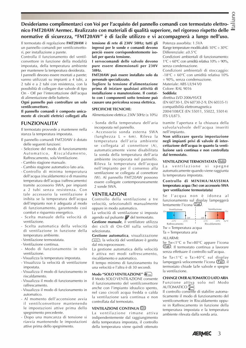
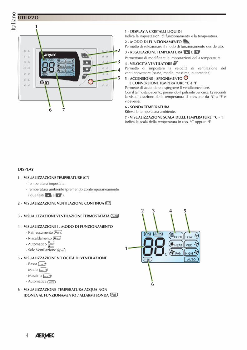
1 - DISPLAY A CRISTALLI LIQUIDIIndica le impostazioni di funzionamento e la temperatura.
2 - MODO DI FUNZIONAMENTO Permette di selezionare il modo di funzionamento desiderato.
3 - REGOLAZIONE TEMPERATURA E
Permettono di modifi care le impostazioni della temperatura.
4 - VELOCITÀ VENTILATORE Permette di impostare la velocità di ventilazione del ventilconvettore (bassa, media, massima, automatica)
5 - ACCENSIONE - SPEGNIMENTO E CONVERSIONE TEMPERATURE °C ÷ °F
Permette di accendere e spegnere il ventilconvettore.Con il termostato spento, premendo il pulsante per circa 12 secondi la visualizzazione della temperatura si converte da °C a °F e viceversa.
6 - SONDA TEMPERATURA Rileva la temperatura ambiente.
7 - VISUALIZZAZIONE SCALA DELLE TEMPERATURE °C - °FIndica la scala della temperatura in uso, °C oppure °F.
DISPLAY
1 - VISUALIZZAZIONE TEMPERATURE (C°)
- Temperatura impostata.
- Temperatura ambiente (premendo contemporaneamente
i due tasti e ).
2 - VISUALIZZAZIONE VENTILAZIONE CONTINUA
3 - VISUALIZZAZIONE VENTILAZIONE TERMOSTATATA
4 - VISUALIZZAZIONE IL MODO DI FUNZIONAMENTO
- Raffrescamento
- Riscaldamento
- Automatico
- Solo Ventilazione
5 - VISUALIZZAZIONE VELOCITÀ DI VENTILAZIONE
- Bassa
- Media
- Massima
- Automatica
6 - VISUALIZZAZIONE TEMPERATURA ACQUA NON
IDONEA AL FUNZIONAMENTO / ALLARMI SONDA
1
2 543
2
1
4
3
5
6 7
6
5
Ital
iano
Premere ripetutamente il pulsante per impostare il modo di funzionamento: I modi di funzionamento sono:
HEAT - Riscaldamento dell’aria. Mantiene la temperatura desiderata nella stanza. Sul display appare il simbolo .
COOL - Raffrescamento e deumidifi cazione dell’aria. Mantiene la temperatura desiderata nella stanza. Sul display appare il simbolo .
AUTOMATICO - Il termostato decide automaticamente il funzionamento in riscaldamento oppure in raffrescamento in funzio-ne della temperatura impostata e della temperature dell’aria nella stanza. Mantiene la temperatura desiderata nella stanza. Sul display appaiono i simboli .
FAN - Il ventilconvettore è attivato in modo “Solo ventilazione”, anche con caldaia, pompa di calore e refrigeratore d’acqua spenti.Sul display appare il simbolo .
UTILIZZO
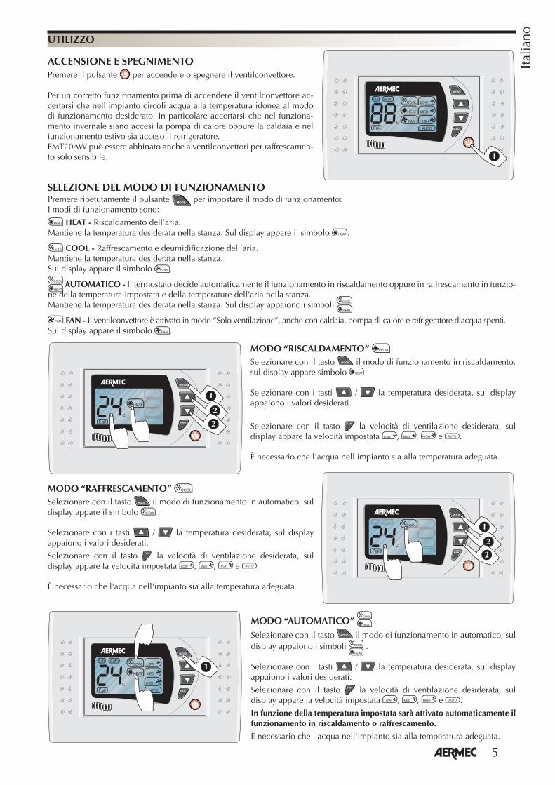
ACCENSIONE E SPEGNIMENTOPremere il pulsante per accendere o spegnere il ventilconvettore.
Per un corretto funzionamento prima di accendere il ventilconvettore ac-certarsi che nell'impianto circoli acqua alla temperatura idonea al modo di funzionamento desiderato. In particolare accertarsi che nel funziona-mento invernale siano accesi la pompa di calore oppure la caldaia e nel funzionamento estivo sia acceso il refrigeratore. FMT20AW può essere abbinato anche a ventilconvettori per raffrescamen-to solo sensibile. �
MODO “AUTOMATICO” Selezionare con il tasto il modo di funzionamento in automatico, sul display appaiono i simboli .
Selezionare con i tasti / la temperatura desiderata, sul display appaiono i valori desiderati.
Selezionare con il tasto la velocità di ventilazione desiderata, sul display appare la velocità impostata , , e .
In funzione della temperatura impostata sarà attivato automaticamente il funzionamento in riscaldamento o raffrescamento.
È necessario che l'acqua nell'impianto sia alla temperatura adeguata.
SELEZIONE DEL MODO DI FUNZIONAMENTO
�
MODO “RISCALDAMENTO” Selezionare con il tasto il modo di funzionamento in riscaldamento, sul display appare simbolo
Selezionare con i tasti / la temperatura desiderata, sul display appaiono i valori desiderati.
Selezionare con il tasto la velocità di ventilazione desiderata, sul display appare la velocità impostata , , e .
È necessario che l'acqua nell'impianto sia alla temperatura adeguata.
�
�
�
�
�
�
MODO “RAFFRESCAMENTO” Selezionare con il tasto il modo di funzionamento in automatico, sul display appare il simbolo .
Selezionare con i tasti / la temperatura desiderata, sul display appaiono i valori desiderati.
Selezionare con il tasto la velocità di ventilazione desiderata, sul display appare la velocità impostata , , e .
È necessario che l'acqua nell'impianto sia alla temperatura adeguata.
6
Ital
iano UTILIZZO
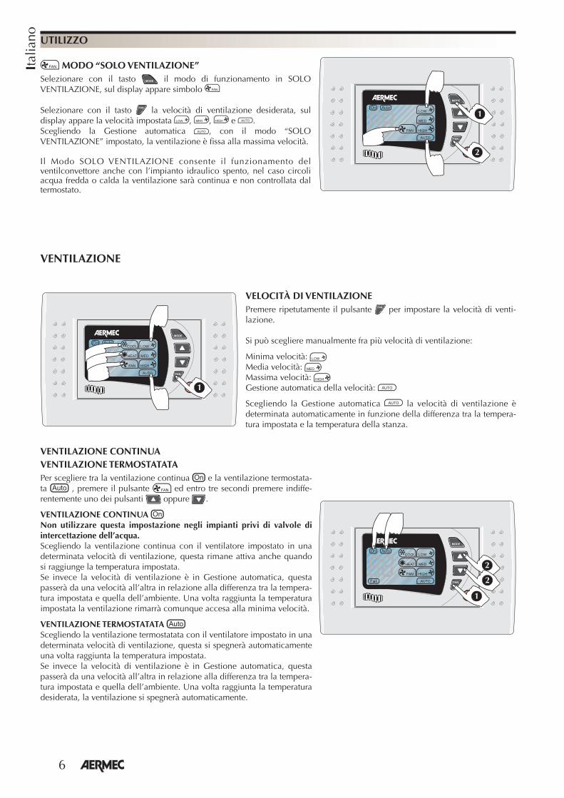
MODO “SOLO VENTILAZIONE”Selezionare con il tasto il modo di funzionamento in SOLO VENTILAZIONE, sul display appare simbolo
Selezionare con il tasto la velocità di ventilazione desiderata, sul display appare la velocità impostata , , e .Scegliendo la Gestione automatica , con il modo “SOLO VENTILAZIONE” impostato, la ventilazione è fi ssa alla massima velocità.
Il Modo SOLO VENTILAZIONE consente il funzionamento del ventilconvettore anche con l’impianto idraulico spento, nel caso circoli acqua fredda o calda la ventilazione sarà continua e non controllata dal termostato.
�
�
VELOCITÀ DI VENTILAZIONEPremere ripetutamente il pulsante per impostare la velocità di venti-lazione.
Si può scegliere manualmente fra più velocità di ventilazione:
Minima velocità: Media velocità: Massima velocità: Gestione automatica della velocità:
Scegliendo la Gestione automatica la velocità di ventilazione è determinata automaticamente in funzione della differenza tra la tempera-tura impostata e la temperatura della stanza.
�
VENTILAZIONE
VENTILAZIONE CONTINUAVENTILAZIONE TERMOSTATATAPer scegliere tra la ventilazione continua e la ventilazione termostata-ta , premere il pulsante ed entro tre secondi premere indiffe-rentemente uno dei pulsanti oppure .
VENTILAZIONE CONTINUA Non utilizzare questa impostazione negli impianti privi di valvole di intercettazione dell’acqua.Scegliendo la ventilazione continua con il ventilatore impostato in una determinata velocità di ventilazione, questa rimane attiva anche quando si raggiunge la temperatura impostata. Se invece la velocità di ventilazione è in Gestione automatica, questa passerà da una velocità all’altra in relazione alla differenza tra la tempera-tura impostata e quella dell’ambiente. Una volta raggiunta la temperatura impostata la ventilazione rimarrà comunque accesa alla minima velocità.
VENTILAZIONE TERMOSTATATA Scegliendo la ventilazione termostatata con il ventilatore impostato in una determinata velocità di ventilazione, questa si spegnerà automaticamente una volta raggiunta la temperatura impostata. Se invece la velocità di ventilazione è in Gestione automatica, questa passerà da una velocità all’altra in relazione alla differenza tra la tempera-tura impostata e quella dell’ambiente. Una volta raggiunta la temperatura desiderata, la ventilazione si spegnerà automaticamente.
�
�
�
7
Ital
iano
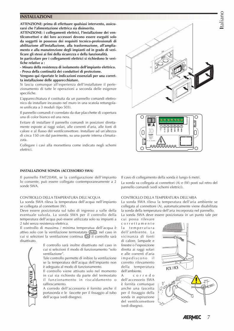
ATTENZIONE: prima di effettuare qualsiasi intervento, assicu-rarsi che l’alimentazione elettrica sia disinserita.ATTENZIONE: i collegamenti elettrici, l’installazione dei ven-tilconvettori e dei loro accessori devono essere eseguiti solo da soggetti in possesso dei requisiti tecnico-professionali di abilitazione all’installazione, alla trasformazione, all’amplia-mento e alla manutenzione degli impianti ed in grado di veri-ficare gli stessi ai fini della sicurezza e della funzionalità. In particolare per i collegamenti elettrici si richiedono le veri-fiche relative a :- Misura della resistenza di isolamento dell’impianto elettrico.- Prova della continuità dei conduttori di protezione.Vengono qui riportate le indicazioni essenziali per una corret-ta installazione delle apparecchiature.Si lascia comunque all’esperienza dell’installatore il perfe-zionamento di tutte le operazioni a seconda delle esigenze specifiche.
L’apparecchiatura é costituita da un pannello comandi elettro-nico da installare incassato nel muro in una scatola rettangola-re unificata a 3 moduli (tipo 503).
Il pannello comandi é corredato da due placchette di copertura una di color bianco ed una nera.
Evitare di installare il pannello comandi in posizioni diretta-mente esposte ai raggi solari, alle correnti d’aria, alle fonti di calore e al flusso del ventilconvettore. Installare ad un’altezza di circa 150 cm dal pavimento, su una parete interna climatiz-zata.
Collegare i cavi alla morsettiera come indicato negli schemi elettrici.
INSTALLAZIONE
106
71
���
���
�
��
��
���
�
�
������
�������������
�� ��������
��
INSTALLAZIONE SONDA (ACCESSORIO SWA)
Il pannello FMT20AW, se la configurazione dell’impianto lo consente, può essere collegato contemporaneamente a 2 sonde SWA.
Il cavo di collegamento della sonda è lungo 6 metri.
La sonda va collegata ai connettori (A) e (W) posti sul retro del pannello comandi (vedi schemi elettrici).
CONTROLLO DELLA TEMPERATURA DELL’ACQUALa sonda SWA rileva la temperatura dell’acqua nell’impianto se collegata al connettore (W). Deve essere posizionata sul tubo di ingresso a valle della eventuale valvola. La sonda SWA per il controllo della temperatura dell’acqua può essere utilizzata solo su impianti a 2 tubi senza resistenza elettrica.Il controllo di massima / minima temperatua dell’acqua è attivo solo con la ventilazione termostatata ; nel caso in cui si selezioni la ventilazione continua il controllo sarà disattivato.
Il controllo sarà inoltre disattivato nel caso in cui si selezioni il modo di funzionamento “solo ventilazione”.Tale controllo permette di inibire la ventilazione se la temperatura dell’acqua dell’impianto non è adeguata al modo di funzionamento.Il controllo viene attivato solo nel momento in cui sia richiesto da parte del termostato i l funzionamento in r i scaldamento o raffrescamento.A corredo dell’accessorio è fornito anche il portasonda e le fascette per il fissaggio al tubo dell’acqua (vedi disegno).
CONTROLLO DELLA TEMPERATURA DELL’ARIALa sonda SWA rileva la temperatura dell’aria ambiente se collegata al connettore (A), automaticamente viene disabilitata la sonda della temperatura dell’aria incorporata nel pannello.La sonda SWA deve essere posizionata in un punto tale per cui possa rilevare c o r r e t t a m e n t e l a t e m p e r a t u r a del l ’ambiente. La vicinanza di fonti di calore, lampade e finestre o l’esposizione diretta ai raggi solari e alle correnti d’aria i m p e d i s c o n o i l corretto rilevamento della temperatura dell’ambiente.A c o r r e d o dell’accessorio SWA è fornita comunque anche una fascetta per il fissaggio della sonda in aspirazione del ventilconvettore (vedi disegno).
� ��� ��� ��
����
�� ��
���WA
TER
8
Engl
ish
FUNCTIONSThe thermostat maintains the temperature set for the room.The FMT20AW control panel is equipped
with the following functions:- Selection of the working mode
Au toma t i c , Hea t ing , Coo l ing , Ventilation Only.
- Manual season change.- Automatic season changeover, air side.- Water minimum temperature control
(hea t ing ) and water maximum temperature control (cooling) by means of the SWA accessory, for 2-pipe systems without resistance.
With the accessory, ventilation is prevented if the temperature of the system water is not suitable for the functioning mode, thus guaranteeing comfort and energy saving.
- manual choice of the ventilation speed;- automatic choice of the ventilation
speed on the basis of the room temperature;
- thermostat-controlled ventilation; - continuous ventilation; - Ventilation only functioning mode.- visualisation of the set temperature;- visualisation of the set ventilation
speed;- visualisation of the Heating working
mode;- visualisation of the Cooling working
mode;- visualisation of the Automatic working
mode;- start-up of the fan coil, maintaining the
settings used before the last switch-off;- after a power failure, the fan coil
restarts keeping the the settings that were active before the power failure;
- air temperature probe incorporated in the panel;
- SWA external probe accessory (length L=6m). It detects the temperature of the room air if connected to the connector (A) . The room air temperature probe, incorporated in the panel, is automatically disabled. t detects the temperature of the water in the system for ventilation consent if connected to the connector (W). Two SWA probes can be connected simultaneously to the FMT20AW panel.
VENTILATIONControls the ventilation, at three speeds which can be selected manually or automatically.The ventilation speed is set by means of the thermostat button .Manual management - the fan uses the On-Off cycles on the selected speed.Automatic management - visualisation
, the fan speed is managed by the microprocessor.The automatic management of the speed is used in the Cooling, Heating and Automatic modes.The minimum working time between one speed and another is 30 seconds.“VENTILATION ONLY” mode The VENTILATION ONLY mode allows for the working of the fan coil even when the hydraulic system is switched off; in the event that cold or hot water is circulating, the ventilation will be continuous and not controlled by the thermostat.
CONTINUOUS VENTILATION The ventilation continues to work even if the set temperature is reached, so the temperature is therefore controlled by means of the opening and closing of the water valve(s) inserted in the system.Do not use this setting in systems without water interception valves, as
the ventilation will be continuous, and not controlled by the thermostat.
T H E R M O S T A T- C O N T R O L L E D VENTILATION The ventilation switches off automatically when the set temperature is reached.
MINIMUM/MAXIMUM water temperature (Tw) check with SWA accessory(for thermostat-controlled ventilation)
If the water is not suitable for the functioning mode, the icon will flash slowly on the screen.
�������� ���������
� �
�����
Tw = Water temperatureTa = Air temperature
ALARMS:
If Tw<1°C or Tw>80°C, the icon is displayed. The thermostat continues operating without checking the water.
If Ta<5°C or Ta>40°C, the icon will flash quickly on the screen, the thermostat closes the valve/s and turns off ventilation.
AUTOMATIC CHANGEOVER, AIR SIDEFunction active only in AUTOMATIC mode.The control allows to automatically establish the functioning mode of the fan coil in Heating or in Cooling mode depending on the temperature set and the room temperature detected by the air probe.
We'd like to congratulate you on your purchase of the Aermec FMT20AW electronic control panel with thermostat. Made from high quality materials, entirely in compliance with the safety standards, “FMT20AW” is easy to use and long-lasting.
The FMT20AW regulating thermostat is a control panel for fan coils, to be assembled on the wall.It controls the working of the fan coil on the basis of the mode set and the room temperature, to maintain the desired temperature.The panels must be wall-mounted. They are used on systems with 4 tubes, 2 tubes and 2 tubes with resistance, with the possibility to connect two valves of the On-Off type for the interception of the water to power the batteries.
Each control panel can control a single fan coil.The control panel only consists of mains voltage (230V 50Hz) electrical circuits; all the inputs for the probes and controls must therefore be correspondingly insulated for this voltage.The valve servo commands must also be scaled for 230V 50Hz.FMT20AW must only be installed by specialised personnel.Disconnect the power supply before beg inn ing any i n s t a l l a t i on o r maintenance operations. Touching live components could electrocute you.
TECHNICAL SPECIFICATIONS:
Power supply: 230V 50Hz (± 10%)Input power: 1.5VAAdjustable temperature range: 10°C - 30°C Differential: ±0.5°CEnvironmental working conditions: 0°C - 60°C with relative humidity 10% - 90%, without condensation.Environmental storage conditions: -18°C - 60°C with relative humidity 10% - 90%, without condensation.Material: ABS UL94 V0Colour: RAL 9016Meets:Directives LVD 2006/95/CE(EN 60730-1, EN 60730-2-9, EN 60335-1);electromagnetic compatibility 2004/108/CE (EN 55011, 55022, 55014) ITS UL873.
Ventilation Ventilation
Cooling Heating
9
Engl
ish
USE
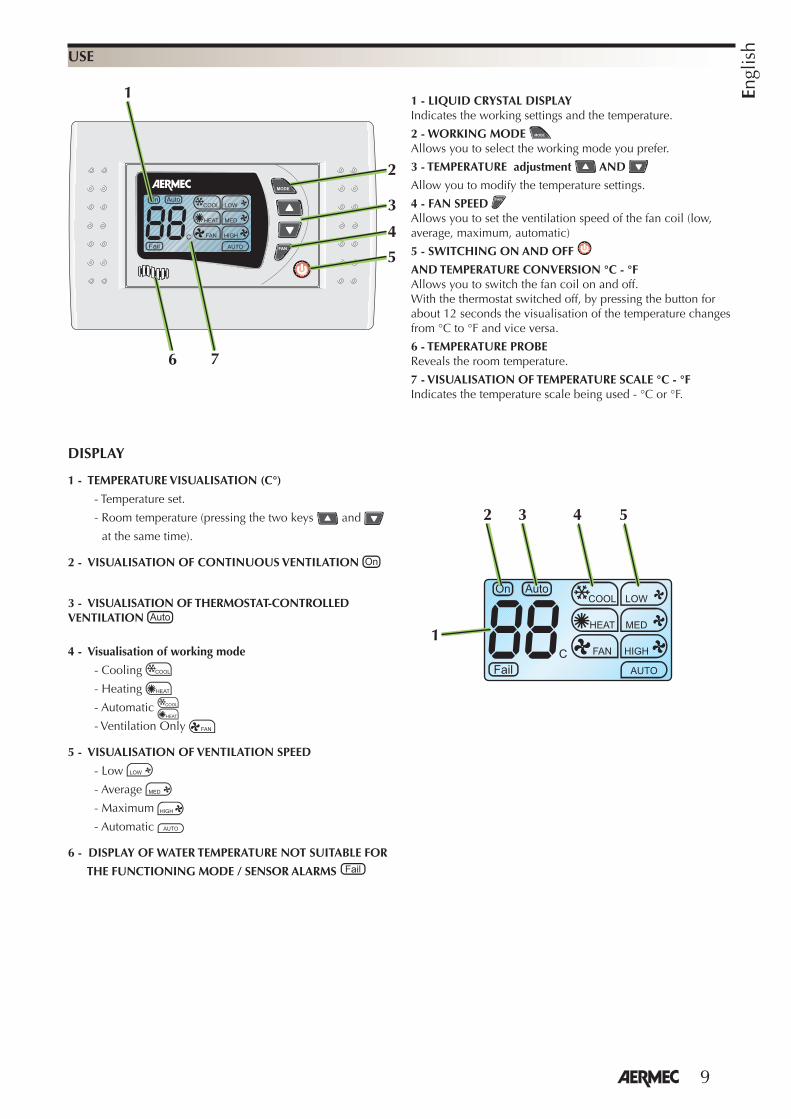
1 - LIQUID CRYSTAL DISPLAYIndicates the working settings and the temperature.
2 - WORKING MODE Allows you to select the working mode you prefer.
3 - TEMPERATURE adjustment AND
Allow you to modify the temperature settings.
4 - FAN SPEED Allows you to set the ventilation speed of the fan coil (low, average, maximum, automatic)
5 - SWITCHING ON AND OFF
AND TEMPERATURE CONVERSION °C - °F Allows you to switch the fan coil on and off.With the thermostat switched off, by pressing the button for about 12 seconds the visualisation of the temperature changes from °C to °F and vice versa.
6 - TEMPERATURE PROBE Reveals the room temperature.
7 - VISUALISATION OF TEMPERATURE SCALE °C - °FIndicates the temperature scale being used - °C or °F.
DISPLAY
1 - TEMPERATURE VISUALISATION (C°)
- Temperature set.
- Room temperature (pressing the two keys and
at the same time).
2 - VISUALISATION OF CONTINUOUS VENTILATION
3 - VISUALISATION OF THERMOSTAT-CONTROLLED VENTILATION
4 - Visualisation of working mode
- Cooling
- Heating
- Automatic
- Ventilation Only
5 - VISUALISATION OF VENTILATION SPEED
- Low
- Average
- Maximum
- Automatic
6 - DISPLAY OF WATER TEMPERATURE NOT SUITABLE FOR
THE FUNCTIONING MODE / SENSOR ALARMS
1
2 543
2
1
4
3
5
6 7
10
Engl
ish
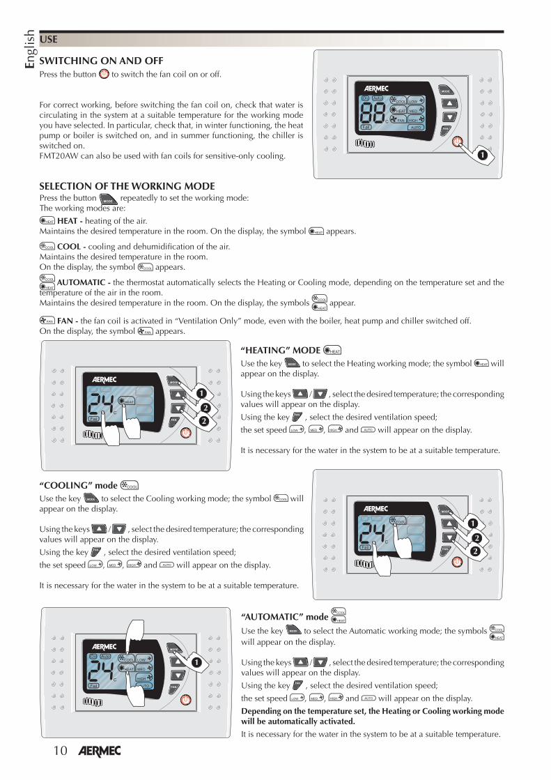
Press the button repeatedly to set the working mode: The working modes are:
HEAT - heating of the air. Maintains the desired temperature in the room. On the display, the symbol appears.
COOL - cooling and dehumidifi cation of the air. Maintains the desired temperature in the room. On the display, the symbol appears.
AUTOMATIC - the thermostat automatically selects the Heating or Cooling mode, depending on the temperature set and the temperature of the air in the room. Maintains the desired temperature in the room. On the display, the symbols appear.
FAN - the fan coil is activated in “Ventilation Only” mode, even with the boiler, heat pump and chiller switched off.On the display, the symbol appears.
USE
SWITCHING ON AND OFFPress the button to switch the fan coil on or off.
For correct working, before switching the fan coil on, check that water is circulating in the system at a suitable temperature for the working mode you have selected. In particular, check that, in winter functioning, the heat pump or boiler is switched on, and in summer functioning, the chiller is switched on. FMT20AW can also be used with fan coils for sensitive-only cooling. �
“AUTOMATIC” mode Use the key to select the Automatic working mode; the symbols will appear on the display.
Using the keys / , select the desired temperature; the corresponding values will appear on the display.
Using the key , select the desired ventilation speed;
the set speed , , and will appear on the display.
Depending on the temperature set, the Heating or Cooling working mode will be automatically activated.
It is necessary for the water in the system to be at a suitable temperature.
SELECTION OF THE WORKING MODE
�
“HEATING” MODE Use the key to select the Heating working mode; the symbol will appear on the display.
Using the keys / , select the desired temperature; the corresponding values will appear on the display.
Using the key , select the desired ventilation speed;
the set speed , , and will appear on the display.
It is necessary for the water in the system to be at a suitable temperature.
�
�
�
�
�
�
“COOLING” mode Use the key to select the Cooling working mode; the symbol will appear on the display.
Using the keys / , select the desired temperature; the corresponding values will appear on the display.
Using the key , select the desired ventilation speed;
the set speed , , and will appear on the display.
It is necessary for the water in the system to be at a suitable temperature.
11
Engl
ish
USE
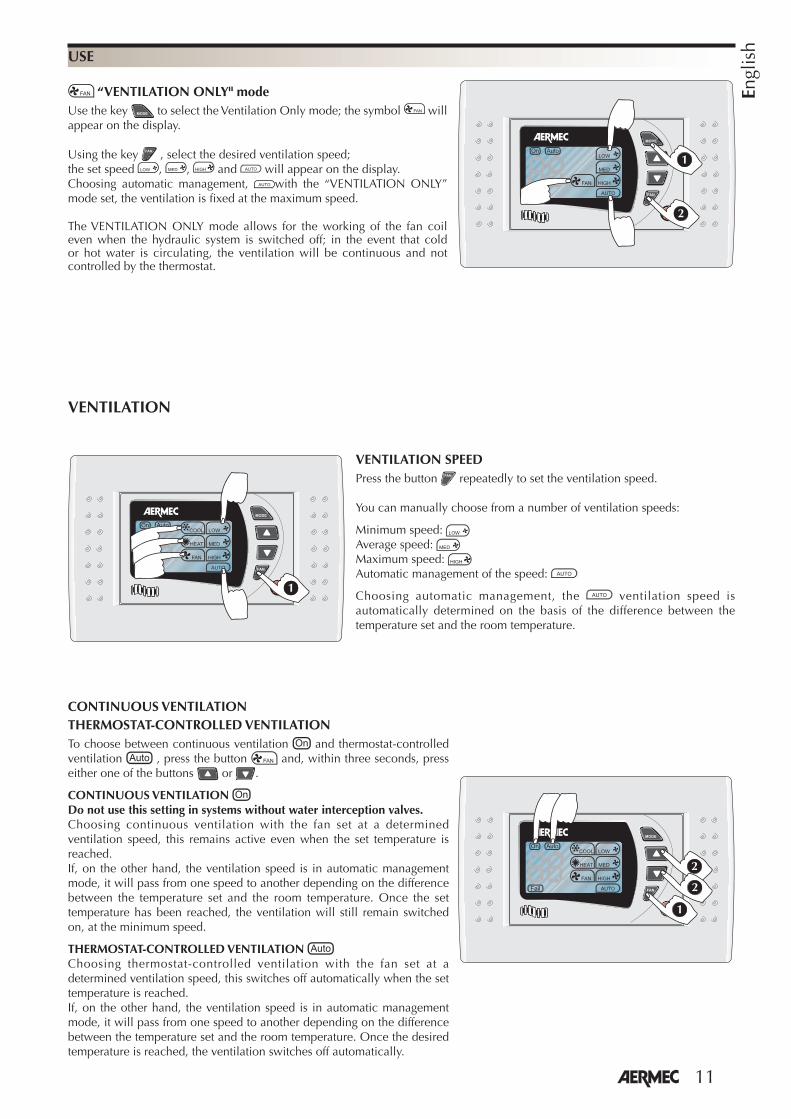
“VENTILATION ONLY" modeUse the key to select the Ventilation Only mode; the symbol will appear on the display.
Using the key , select the desired ventilation speed; the set speed , , and will appear on the display.Choosing automatic management, with the “VENTILATION ONLY” mode set, the ventilation is fi xed at the maximum speed.
The VENTILATION ONLY mode allows for the working of the fan coil even when the hydraulic system is switched off; in the event that cold or hot water is circulating, the ventilation will be continuous and not controlled by the thermostat.
�
�
VENTILATION SPEEDPress the button repeatedly to set the ventilation speed.
You can manually choose from a number of ventilation speeds:
Minimum speed: Average speed: Maximum speed: Automatic management of the speed:
Choosing automatic management, the ventilation speed is automatically determined on the basis of the difference between the temperature set and the room temperature.
�
VENTILATION
CONTINUOUS VENTILATIONTHERMOSTAT-CONTROLLED VENTILATIONTo choose between continuous ventilation and thermostat-controlled ventilation , press the button and, within three seconds, press either one of the buttons or .
CONTINUOUS VENTILATION Do not use this setting in systems without water interception valves.Choosing continuous ventilation with the fan set at a determined ventilation speed, this remains active even when the set temperature is reached. If, on the other hand, the ventilation speed is in automatic management mode, it will pass from one speed to another depending on the difference between the temperature set and the room temperature. Once the set temperature has been reached, the ventilation will still remain switched on, at the minimum speed.
THERMOSTAT-CONTROLLED VENTILATION Choosing thermostat-controlled ventilation with the fan set at a determined ventilation speed, this switches off automatically when the set temperature is reached. If, on the other hand, the ventilation speed is in automatic management mode, it will pass from one speed to another depending on the difference between the temperature set and the room temperature. Once the desired temperature is reached, the ventilation switches off automatically.
�
�
�
12
Engl
ish
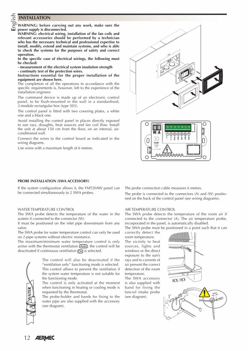
WARNING: before carrying out any work, make sure the power supply is disconnected.WARNING: electrical wiring, installation of the fan coils and relevant accessories should be performed by a technician who has the necessary technical and professional expertise to install, modify, extend and maintain systems, and who is able to check the systems for the purposes of safety and correct operation. In the specific case of electrical wirings, the following must be checked:- measurement of the electrical system insulation strength- continuity test of the protection wires.Instructions essential for the proper installation of the equipment are shown here.The completion of all the operations in accordance with the specific requirements is, however, left to the experience of the installation engineer.The command device is made up of an electronic control panel, to be flush-mounted in the wall in a standardised, 3-module rectangular box (type 503).The control panel is fitted with two covering plates, a white one and a black one.Avoid installing the control panel in places directly exposed to sun rays, draughts, heat sources and fan coil flow. Install the unit at about 150 cm from the floor, on an internal, air-conditioned wall.Connect the wires to the control board as indicated in the wiring diagrams.Use wires with a maximum length of 6 metres.
INSTALLATION
106
71
���
���
�
��
��
���
�
�
������
�������������
�� ��������
��
PROBE INSTALLATION (SWA ACCESSORY)
If the system configuration allows it, the FMT20AW panel can be connected simultaneously to 2 SWA probes.
The probe connection cable measures 6 metres.
The probe is connected to the connectors (A) and (W) positio-ned on the back of the control panel (see wiring diagrams).
WATER TEMPERATURE CONTROLThe SWA probe detects the temperature of the water in the system if connected to the connector (W).It must be positioned on the inlet pipe downstream from any valve. The SWA probe for water temperature control can only be used on 2-pipe systems without electric resistance.The maximum/minimum water temperature control is only active with the thermostat ventilation ; the control will be deactivated if continuous ventilation is selected.
The control will also be deactivated if the “ventilation only” functioning mode is selected.This control allows to prevent the ventilation if the system water temperature is not suitable for the functioning mode.The control is only activated at the moment when functioning in heating or cooling mode is requested by the thermostat.The probe-holder and bands for fixing to the water pipe are also supplied with the accessory (see diagram).
AIR TEMPERATURE CONTROLThe SWA probe detects the temperature of the room air if connected to the connector (A). The air temperature probe, incorporated in the panel, is automatically disabled.The SWA probe must be positioned in a point such that it can correctly detect the room temperature. The vicinity to heat sources, lights and windows or the direct exposure to the sun’s rays and to currents of air prevent the correct detection of the room temperature.The SWA accessory is also supplied with band for fixing the fancoil intake probe (see diagram).
� ��� ��� ��
����
�� ��
���
WA
TER
13
Fran
çais
FONCTIONNALITELe thermostat conserve dans la pièce la température réglée.Le panneau de commande FMT20
dispose des fonctions suivantes :- Sélection du mode de fonctionnement :
automatique, chauffage, refroidissement, ventilation uniquement.
- Changement de saison manuel.- Changement de saison automatique
côté air.- Contrôle de la température minimale de
l’eau (chauffage) et de la température maximale de l’eau (rafraîchissement) au moyen de l’accessoire SWA, pour des installations à 2 tuyaux sans résistance.
Avec cet accessoire, la ventilation est désactivée si la température de l’eau de l’installation n’est pas adaptée au mode de fonctionnement, ce qui garantit confort et économie d’énergie.
- sélection manuelle de la vitesse de ventilation;
- choix automatique de la vitesse de ventilation en fonction de la température ambiante;
- ventilation thermostatée; - ventilation continue; - Mode de fonctionnement en ventilation
seule.- affiche la température paramétrée;- affiche la vitesse de ventilation
paramétrée;- affiche le mode de fonctionnement en
chauffage;- affiche le mode de fonctionnement en
refroidissement;- affiche le mode de fonctionnement en
automatique;- démarrage du ventilo-convecteur au
moment de l'allumage en conservant les réglages actifs avant l'extinction précédente;
- redémarrage après une coupure de tension en conservant les réglages actifs avant l'extinction;
- sonde de température de l’air intégrée dans le panneau.
- Accessoire sonde extérieure SWA (longueur L = 6m). Elle relève la température de l'air ambiant si elle est reliée au connecteur (A) et la sonde de température de l'air ambiant, incorporée au panneau, est automatiquement désactivée. Elle relève la température de l'eau dans l'installation pour autoriser la ventilation si elle est reliée au connecteur (W). Il est possible de connecter simultanément 2 sondes SWA au panneau FMT20AW.
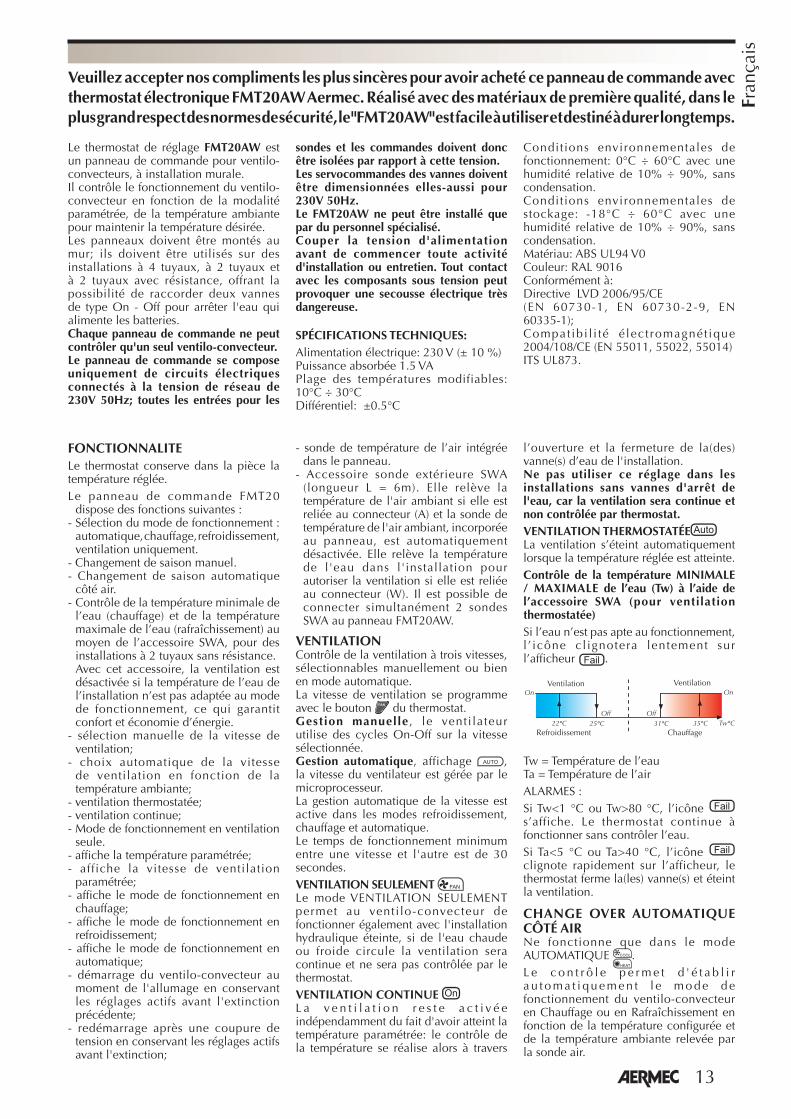
VENTILATIONContrôle de la ventilation à trois vitesses, sélectionnables manuellement ou bien en mode automatique.La vitesse de ventilation se programme avec le bouton du thermostat.Gestion manuelle , le venti lateur utilise des cycles On-Off sur la vitesse sélectionnée.Gestion automatique, affichage , la vitesse du ventilateur est gérée par le microprocesseur.La gestion automatique de la vitesse est active dans les modes refroidissement, chauffage et automatique.Le temps de fonctionnement minimum entre une vitesse et l'autre est de 30 secondes.VENTILATION SEULEMENT Le mode VENTILATION SEULEMENT permet au venti lo-convecteur de fonctionner également avec l'installation hydraulique éteinte, si de l'eau chaude ou froide circule la ventilation sera continue et ne sera pas contrôlée par le thermostat.VENTILATION CONTINUE L a v e n t i l a t i o n r e s t e a c t i v é e indépendamment du fait d'avoir atteint la température paramétrée: le contrôle de la température se réalise alors à travers
l’ouverture et la fermeture de la(des) vanne(s) d’eau de l'installation.Ne pas utiliser ce réglage dans les installations sans vannes d'arrêt de l'eau, car la ventilation sera continue et non contrôlée par thermostat.VENTILATION THERMOSTATÉELa ventilation s’éteint automatiquement lorsque la température réglée est atteinte.Contrôle de la température MINIMALE / MAXIMALE de l’eau (Tw) à l’aide de l’accessoire SWA (pour ventilation thermostatée)Si l’eau n’est pas apte au fonctionnement, l ’ icône cl ignotera lentement sur l’afficheur .
�������� ���������
� �
�����
Tw = Température de l’eauTa = Température de l’airALARMES :Si Tw<1 °C ou Tw>80 °C, l’icône s’affiche. Le thermostat continue à fonctionner sans contrôler l’eau.Si Ta<5 °C ou Ta>40 °C, l’icône clignote rapidement sur l’afficheur, le thermostat ferme la(les) vanne(s) et éteint la ventilation.
CHANGE OVER AUTOMATIQUE CÔTÉ AIRNe fonctionne que dans le mode AUTOMATIQUE .L e c o n t r ô l e p e r m e t d ' é t a b l i r a u t o m a t i q u e m e n t l e m o d e d e fonctionnement du ventilo-convecteur en Chauffage ou en Rafraîchissement en fonction de la température configurée et de la température ambiante relevée par la sonde air.
Veuillez accepter nos compliments les plus sincères pour avoir acheté ce panneau de commande avec thermostat électronique FMT20AW Aermec. Réalisé avec des matériaux de première qualité, dans le plus grand respect des normes de sécurité, le "FMT20AW" est facile à utiliser et destiné à durer longtemps.
Le thermostat de réglage FMT20AW est un panneau de commande pour ventilo-convecteurs, à installation murale.Il contrôle le fonctionnement du ventilo-convecteur en fonction de la modalité paramétrée, de la température ambiante pour maintenir la température désirée.Les panneaux doivent être montés au mur; ils doivent être utilisés sur des installations à 4 tuyaux, à 2 tuyaux et à 2 tuyaux avec résistance, offrant la possibilité de raccorder deux vannes de type On - Off pour arrêter l'eau qui alimente les batteries.Chaque panneau de commande ne peut contrôler qu'un seul ventilo-convecteur.Le panneau de commande se compose uniquement de circuits électriques connectés à la tension de réseau de 230V 50Hz; toutes les entrées pour les
sondes et les commandes doivent donc être isolées par rapport à cette tension.Les servocommandes des vannes doivent être dimensionnées elles-aussi pour 230V 50Hz.Le FMT20AW ne peut être installé que par du personnel spécialisé.Couper la tension d'alimentation avant de commencer toute activité d'installation ou entretien. Tout contact avec les composants sous tension peut provoquer une secousse électrique très dangereuse.
SPÉCIFICATIONS TECHNIQUES:Alimentation électrique: 230 V (± 10 %)Puissance absorbée 1.5 VAPlage des températures modifiables: 10°C ÷ 30°C Différentiel: ±0.5°C
Conditions environnementales de fonctionnement: 0°C ÷ 60°C avec une humidité relative de 10% ÷ 90%, sans condensation.Conditions environnementales de stockage: -18°C ÷ 60°C avec une humidité relative de 10% ÷ 90%, sans condensation.Matériau: ABS UL94 V0Couleur: RAL 9016Conformément à:Directive LVD 2006/95/CE(EN 60730-1, EN 60730-2-9, EN 60335-1);Compat ibi l i té é lect romagnét ique 2004/108/CE (EN 55011, 55022, 55014) ITS UL873.
Ventilation Ventilation
Refroidissement Chauffage
14
Fran
çais UTILISATION
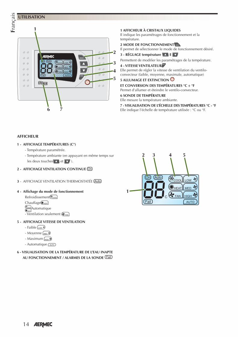
1 AFFICHEUR À CRISTAUX LIQUIDESIl indique les paramétrages de fonctionnement et la température.
2 MODE DE FONCTIONNEMENTIl permet de sélectionner le mode de fonctionnement désiré.
3 - RÉGLAGE température E
Permettent de modifi er les paramétrages de la température.
4 - VITESSE VENTILATEURElle permet de régler la vitesse de ventilation du ventilo-convecteur (faible, moyenne, maximale, automatique)
5 ALLUMAGE ET EXTINCTION
ET CONVERSION DES TEMPÉRATURES °C ÷ °F Permet d'allumer et éteindre le ventilo-convecteur.
6 SONDE DE TEMPÉRATURE Elle mesure la température ambiante.
7 - VISUALISATION DE L’ÉCHELLE DES TEMPÉRATURES °C - °FElle indique l’échelle de température utilisée : °C ou °F.
AFFICHEUR
1 - AFFICHAGE TEMPÉRATURES (C°)
- Température paramétrée.
- Température ambiante (en appuyant en même temps sur
les deux touches et ).
2 - AFFICHAGE VENTILATION CONTINUE
3 - AFFICHAGE VENTILATION THERMOSTATÉE
4 - Affi chage du mode de fonctionnement
Refroidissement
Chauffage
Automatique
- Ventilation seulement
5 - AFFICHAGE VITESSE DE VENTILATION
- Faible
- Moyenne
- Maximum
- Automatique
6 - VISUALISATION DE LA TEMPÉRATURE DE L’EAU INAPTE
AU FONCTIONNEMENT / ALARMES DE LA SONDE
1
2 543
2
1
4
3
5
6 7

15
Fran
çais
Appuyer plusieurs fois sur le bouton pour paramétrer le mode de fonctionnement: Les modes de fonctionnement sont:
HEAT - Chauffage de l'air. Maintient la température désirée dans la pièce. Sur l'affi cheur le symbole s'affi che .
COOL - Refroidissement et déshumidifi cation de l'air. Maintient la température désirée dans la pièce. Sur l'affi cheur le symbole s'affi che .
AUTOMATIQUE - Le thermostat décide automatiquement le fonctionnement en chauffage ou bien en refroidissement en fonction de la température paramétrée et de la température de l'air dans la pièce. Maintient la température désirée dans la pièce. Sur l'affi cheur les symboles s'affi chent .
FAN - Le ventilo-convecteur est activé en mode “Ventilation seulement”, même avec chaudière, pompe de chaleur et chiller éteints.Sur l'affi cheur le symbole s'affi che .
UTILISATION
ALLUMAGE ET EXTINCTIONAppuyer sur le bouton pour allumer ou éteindre le ventilo-convecteur.
Pour un bon fonctionnement, avant d'allumer le ventilo-convecteur, s'assurer que dans l'installation circule de l'eau à la température adéquate selon le mode de fonctionnement souhaité. En particulier, s'assurer que dans le fonctionnement d'hiver soient allumés la pompe à chaleur ou la chaudière, et que dans le fonctionnement d'été soit allumé le refroidisseur. Le FMT20AW peut se combiner avec des ventilo-convecteurs pour refroidissement seulement sensible.
�
MODE “AUTOMATIQUE” Sélectionner avec la touche le mode de fonctionnement en automatique, les symboles s'affi chent sur l'affi cheur
Sélectionner avec les touches / la température désirée, les valeurs désirées s'affi chent sur l'affi cheur.
Sélectionner avec la touche la vitesse de ventilation désirée, sur l'affi cheur s'affi che la vitesse paramétrée , , et .
En fonction de la température paramétrée le fonctionnement en chauffage ou refroidissement sera activé automatiquement.
Il est nécessaire que l'eau de l'installation soit à la température adéquate.
SÉLECTION DU MODE DE FONCTIONNEMENT
�
MODE CHAUFFAGESélectionner avec la touche le mode de fonctionnement en chauffage, le symbole s'affi che sur l'affi cheur
Sélectionner avec les touches / la température désirée, les valeurs désirées s'affi chent sur l'affi cheur.
Sélectionner avec la touche la vitesse de ventilation désirée, sur l'affi cheur s'affi che la vitesse paramétrée , , et .
Il est nécessaire que l'eau de l'installation soit à la température adéquate.
�
�
�
�
�
�
MODE “REFROIDISSEMENT” Sélectionner avec la touche le mode de fonctionnement en automatique, le symbole s'affi che sur l'affi cheur
Sélectionner avec les touches / la température désirée, les valeurs désirées s'affi chent sur l'affi cheur.
Sélectionner avec la touche la vitesse de ventilation désirée, sur l'affi cheur s'affi che la vitesse paramétrée , , et .
Il est nécessaire que l'eau de l'installation soit à la température adéquate.
16
Fran
çais UTILISATION
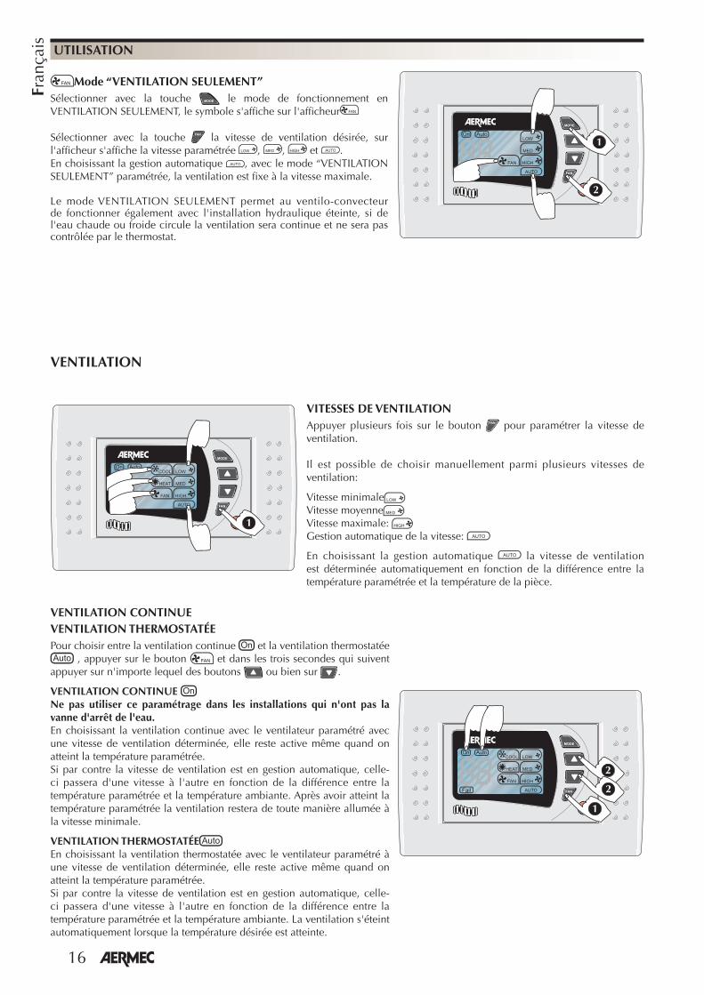
Mode “VENTILATION SEULEMENT”Sélectionner avec la touche le mode de fonctionnement en VENTILATION SEULEMENT, le symbole s'affi che sur l'affi cheur
Sélectionner avec la touche la vitesse de ventilation désirée, sur l'affi cheur s'affi che la vitesse paramétrée , , et .En choisissant la gestion automatique , avec le mode “VENTILATION SEULEMENT” paramétrée, la ventilation est fi xe à la vitesse maximale.
Le mode VENTILATION SEULEMENT permet au ventilo-convecteur de fonctionner également avec l'installation hydraulique éteinte, si de l'eau chaude ou froide circule la ventilation sera continue et ne sera pas contrôlée par le thermostat.
�
�
VITESSES DE VENTILATIONAppuyer plusieurs fois sur le bouton pour paramétrer la vitesse de ventilation.
Il est possible de choisir manuellement parmi plusieurs vitesses de ventilation:
Vitesse minimaleVitesse moyenneVitesse maximale: Gestion automatique de la vitesse:
En choisissant la gestion automatique la vitesse de ventilation est déterminée automatiquement en fonction de la différence entre la température paramétrée et la température de la pièce.
�
VENTILATION
VENTILATION CONTINUEVENTILATION THERMOSTATÉEPour choisir entre la ventilation continue et la ventilation thermostatée
, appuyer sur le bouton et dans les trois secondes qui suivent appuyer sur n'importe lequel des boutons ou bien sur .
VENTILATION CONTINUE Ne pas utiliser ce paramétrage dans les installations qui n'ont pas la vanne d'arrêt de l'eau.En choisissant la ventilation continue avec le ventilateur paramétré avec une vitesse de ventilation déterminée, elle reste active même quand on atteint la température paramétrée. Si par contre la vitesse de ventilation est en gestion automatique, celle-ci passera d'une vitesse à l'autre en fonction de la différence entre la température paramétrée et la température ambiante. Après avoir atteint la température paramétrée la ventilation restera de toute manière allumée à la vitesse minimale.
VENTILATION THERMOSTATÉEEn choisissant la ventilation thermostatée avec le ventilateur paramétré à une vitesse de ventilation déterminée, elle reste active même quand on atteint la température paramétrée. Si par contre la vitesse de ventilation est en gestion automatique, celle-ci passera d'une vitesse à l'autre en fonction de la différence entre la température paramétrée et la température ambiante. La ventilation s'éteint automatiquement lorsque la température désirée est atteinte.
�
�
�
17
Fran
çais
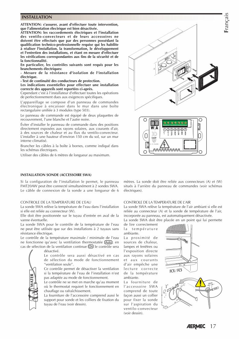
ATTENTION: s'assurer, avant d'effectuer toute intervention, que l'alimentation électrique est bien désactivée.ATTENTION: les raccordements électriques et l'installation des ventilo-convecteurs et de leurs accessoires ne doivent être effectués que par des personnes possédant la qualification technico-professionnelle requise qui les habilite à réaliser l'installation, la transformation, le développement et l'entretien des installations, et étant en mesure d'effectuer les vérifications correspondantes aux fins de la sécurité et de la fonctionnalité. En particulier, les contrôles suivants sont requis pour les branchements électriques:- Mesure de la résistance d'isolation de l'installation électrique.- Test de continuité des conducteurs de protection.Les indications essentielles pour effectuer une installation correcte des appareils sont reportées ci-après.Cependant c'est à l'installateur d'effectuer toutes les opérations de perfectionnement dues aux exigences spécifiques.L’appareillage se compose d'un panneau de commandes électronique à encaisser dans le mur dans une boîte rectangulaire unifiée à 3 modules (type 503).Le panneau de commande est équipé de deux plaquettes de recouvrement, l’une blanche et l’autre noire.Éviter d’installer le panneau de commande dans des positions directement exposées aux rayons solaires, aux courants d’air, à des sources de chaleur et au flux du ventilo-convecteur. L’installer à une hauteur d’environ 150 cm du sol, sur un mur interne climatisé.Brancher les câbles à la boîte à bornes, comme indiqué dans les schémas électriques.Utiliser des câbles de 6 mètres de longueur au maximum.
INSTALLATION
106
71
���
���
�
��
��
���
�
�
������
�������������
�� ��������
��
INSTALLATION SONDE (ACCESSOIRE SWA)
Si la configuration de l’installation le permet, le panneau FMT20AW peut être connecté simultanément à 2 sondes SWA.Le câble de connexion de la sonde a une longueur de 6
mètres. La sonde doit être reliée aux connecteurs (A) et (W) situés à l’arrière du panneau de commandes (voir schémas électriques).
CONTROLE DE LA TEMPERATURE DE L’EAULa sonde SWA relève la température de l’eau dans l’installation si elle est reliée au connecteur (W).Elle doit être positionnée sur le tuyau d’entrée en aval de la vanne éventuelle. La sonde SWA pour le contrôle de la température de l’eau ne peut être utilisée que sur des installations à 2 tuyaux sans résistance électrique.Le contrôle de la température maximale / minimale de l’eau ne fonctionne qu’avec la ventilation thermostatée ; en cas de sélection de la ventilation continue le contrôle sera
désactivé.Le contrôle sera aussi désactivé en cas de sélection du mode de fonctionnement “ventilation seule”.Ce contrôle permet de désactiver la ventilation si la température de l’eau de l’installation n’est pas adaptée au mode de fonctionnement. Le contrôle ne se met en marche qu’au moment où le thermostat requiert le fonctionnement en chauffage ou rafraîchissement. La fourniture de l’accessoire comprend aussi le support pour sonde et les colliers de fixation du tuyau de l’eau (voir dessin).
CONTROLE DE LA TEMPERATURE DE L’AIRLa sonde SWA relève la température de l’air ambiant si elle est reliée au connecteur (A) et la sonde de température de l’air, incorporée au panneau, est automatiquement désactivée. La sonde SWA doit être placée en un point qui lui permette de lire correctement l a t e m p é r a t u r e ambiante. La p rox imi té de sources de chaleur, lampes et fenêtres ou l’exposition directe aux rayons solaires e t aux cou ran t s d’air empêche une l e c t u r e c o r r e c t e de la température ambiante. La fourn i tu re de l ’accessoi re SWA comprend de toute façon aussi un collier pour fixer la sonde sur l’aspiration du ventilo-convecteur (voir dessin).
� ��� ��� ��
����
�� ��
���WA
TER
18
Deu
tsch
e
Wir möchten Sie zum Kauf der Bedientafel mit elektronischem Thermostat FMT20AW Aermec beglückwünschen. Das Modell "FMT20AW" ist aus erstklassigen Materialen und unter strenger Beachtung der Sicherheitsbestimmungen hergestellt und benutzerfreundlich, wodurch es Sie lange begleiten wird.
FUNKTIONSWEISED a s Th e r m o s t a t s o r g t f ü r d i e Aufrechterhaltung der eingestellten Temperatur im Raum.Die Bedientafel FMT20AW verfügt über
folgende Funktionen:- Wahl der Betriebsart: Automatisch,
Heizbetrieb, Kühlbetrieb oder nur Lüftung;
- manuelle Saisonumschaltung;- automatische Saisonumschaltung
luftseitig;- Kontrolle der Mindest-Wassertemperatur
(Erwärmung) und der Maximal-Wassertemperatur (Kühlung), mittels SWA Zubehör, für Anlagen mit zwei Rohren, ohne Widerstand. Mit diesem Zubehörteil, wird die Ventilierung gehemmt, wenn die Wassertemperatur der Anlage, nicht dem Funktionsmodus entspricht, so wird Komfort und Energieersparnis garantiert.
- manuelle Wahl der Gebläsedrehzahl;- automatische Wahl der Gebläsedrehzahl
je nach der Raumtemperatur;- durch Thermostat gesteuerte Belüftung; - Dauerbelüftung; - Funktionsmodus, nur Ventilierung- Anzeige der eingerichteten Temperatur;- A n z e i g e d e r e i n g e r i ch t e t e n
Gebläsedrehzahl;- Anzeige der Betriebsart Heizen;- Anzeige der Betriebsart Kühlen;- Anzeige der Betriebsart Automatisch;- B e i m E i n s c h a l t e n w i r d d e r
Gebläsekonvektor gestartet, wobei die Einstellungen beibehalten werden, die vor dem letzten Ausschalten aktiv waren;
- s c h a l t e t s i c h n a c h e i n e m Spannungsausfall unter Beibehaltung der vor der Abschaltung aktiven Einstellungen wieder ein;
- Lufttemperaturfühler in Bedientafel eingebaut.
- Zubehörteil SWA Außensonde (Länge
L = 6 m). Erkennt die Raumtemperatur, wenn mi t dem Verb inde r (A ) verbunden, automatisch wird die im Paneel integrierte Raumtemperatur-Sonde deakt iv ier t . Erkennt die Wassertemperatur der Anlage, zur Befähigung der Ventilierung, falls verbunden mit Verbinder (W). Mit dem Paneel FMT20AW können gleichzeitig 2 SWA Sonden verbunden werden.
LÜFTUNGSteuerung der Lüf tung mi t dre i Drehzah len , d ie manue l l ode r automatisch wählbar sind.Die Gebläsedrehzahl wird durch Betätigen der Taste des Thermostats eingerichtet.Manuelle Steuerung, das Gebläse verwendet On-Off-Zyklen mit der gewählten Drehzahl.Automatische Steuerung, Anzeige , die Gebläsedrehzahl wird durch einen Mikroprozessor gesteuert.Die automatische Steuerung der Drehzahl ist bei den Betriebsarten Kühlen, Heizen und Automatisch aktiv.Die Mindestbetriebszeit zwischen den einzelnen Drehzahlen beträgt 30 Sekunden.Betriebsart “NUR LÜFTUNG” Die Bet r iebsar t NUR LÜFTUNG e r m ö g l i c h t d e n B e t r i e b d e s G e b l ä s e k o n v e k t o r s a u c h b e i ausgeschalteter Hydraulikanlage, d.h. wenn kaltes oder warmes Wasser fließt erfolgt die Lüftung kontinuierlich und wird nicht durch das Thermostat gesteuert.
DAUERLÜFTUNG Die Lüftung bleibt unabhängig vom Erreichen der eingestellten Temperatur aktiv. Die Steuerung der Temperatur erfolgt somit durch das Öffnen und Schließen des/der Wasserventils/e in der Anlage.
Verwenden Sie diese Einstellung nicht bei Anlagen ohne Wasserabsperrventile, da die Lüftung ohne Unterbrechung erfolgt und nicht durch das Thermostat gesteuert wird.
DURCH THERMOSTAT GESTEUERTE LÜFTUNG Die Lüftung schaltet sich automatisch aus, wenn die eingestellte Temperatur erreicht wird.S t e u e r u n g v o n M I N I M U M /MAXIMUM der Wassertemperatur (Tw) mit dem Zubehörteil SWA (für thermostatgesteuerte Lüftung)Wenn das Wasser nicht der Funktion entspricht, erscheint langsam blinkend auf dem Display das Symbol .
�������� ���������
� �
�����
Tw = WassertemperaturTa = LufttemperaturSTÖRMELDUNGEN:Wenn Tw<1°C oder Tw>80°C erscheint das Symbol . Das Thermostat arbeitet weiter, ohne die Steuerung des Wassers zu beeinflussen.Wenn Ta<5°C oder Ta>40°C erscheint schnell blinkend auf dem Display das Symbol , das Thermostat schließt das/die Ventil/e und schaltet die Lüftung ab.
AUTOMATISCHER LUFTSEITIGER CHANGE OVERF u n k t i o n n u r i n B e t r i e b s a r t AUTOMATISCH aktiv.Durch d ie Kont ro l le kann man automatisch den Funktionsmodus des Gebläsekonvektoren festlegen, Erwärmung oder Kühlung, je nach eingestellter Temperatur und durch die Luftsonde erkannte Raumtemperatur.
Das Regelthermostat FMT20AW ist eine Bedientafel für Gebläsekonvektoren zur Wandmontage.E s s t e u e r t d e n B e t r i e b d e s Gebläsekonvektors je nach der eingerichteten Betriebsart und der Raumtemperatur, um die gewünschte Temperatur aufrecht zu erhalten.Die Bedientafeln müssen an der Wand montiert werden. Sie müssen mit in 4-Leiter-, 2-Leiter und 2-Leiter-Systemen mit Heizregister verwendet werden, wobei die Möglichkeit besteht, zwei Ventile vom Typ On - Off zur Absperrung der Wasserzufuhr der Wärmetauscher anzuschließen.
Jede Bedientafel kann nur einen Gebläsekonvektor steuern.Die Bedientafel besteht ausschließlich aus elektrischen Schaltkreisen, die an die Netzspannung von 230 V angeschlossen sind. Alle Eingänge für Sonden und Steuerungen müssen daher für diese Spannung entsprechend isoliert werden.Die Servosteuerungen der Ventile müssen zudem für 230V 50Hz bemessen werden.FMT20AW darf nur durch Fachpersonal installiert werden.Schalten Sie die Versorgungsspannung ab, bevor Sie Installations- oder Wartungsarbeiten ausführen. Eine Berührung der unter Spannung stehenden Bauteile kann zu gefährlichen Stromschlägen führen.
TECHNISCHE DATEN:Stromversorgung: 230V 50Hz (± 10%)Leistungsaufnahme: 1.5VAÄnderbarer Temperaturbereich: 10°C ÷ 30°C Differential: ±0.5°CBetriebsbedingungen in der Umgebung: 0°C ÷ 60°C bei relativer Feuchtigkeit von 10% ÷ 90%, ohne Kondensation.Lagerbedingungen in der Umgebung: -18°C ÷ 60°C bei relativer Feuchtigkeit von 10% ÷ 90%, ohne Kondensation.Material: ABS UL94 V0Farbe: RAL 9016Erfüllt:Richtlinie LVD 2006/95/CE(EN 60730-1, EN 60730-2-9, EN 60335-1);Elektromagnetische Verträglichkeit 2004/108/CE (EN 55011, 55022, 55014) ITS UL873.
Lüftung Lüftung
HeizbetriebKühlbetrieb
19
Deu
tsch
e
VERWENDUNG
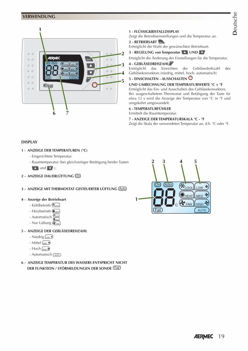
1 - FLÜSSIGKRISTALLDISPLAY Zeigt die Betriebseinstellungen und die Temperatur an.
2 - BETRIEBSART Ermöglicht die Wahl der gewünschten Betriebsart.
3 - REGELUNG von Temperatur UND
Emöglicht die Änderung der Einstellungen für die Temperatur.
4 - GEBLÄSEDREHZAHLErmöglicht das Einrichten der Gebläsedrehzahl des Gebläsekonvektors (niedrig, mittel, hoch, automatisch)
5 - EINSCHALTEN - AUSSCHALTEN
UND UMRECHNUNG DER TEMPERATURWERTE °C ÷ °FErmöglicht das Ein- und Ausschalten des Gebläsekonvektors.Bei ausgeschaltetem Thermostat und Betätigung der Taste für etwa 12 s wird die Anzeige der Temperatur von °C in °F und umgekehrt umgewandelt.
6 - TEMPERATURFÜHLER Ermittelt die Raumtemperatur.
7 - ANZEIGE DER TEMPERATURSKALA °C - °FZeigt die Skala der verwendeten Temperatur an, d.h. °C oder °F.
DISPLAY
1 - ANZEIGE DER TEMPERATUREN (°C)
- Eingerichtete Temperatur.
- Raumtemperatur (bei gleichzeitiger Betätigung beider Tasten
und ).
2 - ANZEIGE DAUERLÜFTUNG
3 - ANZEIGE MIT THERMOSTAT GESTEUERTER LÜFTUNG
4 - Anzeige der Betriebsart
- Kühlbetrieb
- Heizbetrieb
- Automatisch
- Nur Lüftung
5 - ANZEIGE DER GEBLÄSEDREHZAHL
- Niedrig
- Mittel
- Hoch
- Automatisch
6 - ANZEIGE TEMPERATUR DES WASSERS ENTSPRICHT NICHT
DER FUNKTION / STÖRMELDUNGEN DER SONDE
1
2 543
2
1
4
3
5
6 7
20
Deu
tsch
e
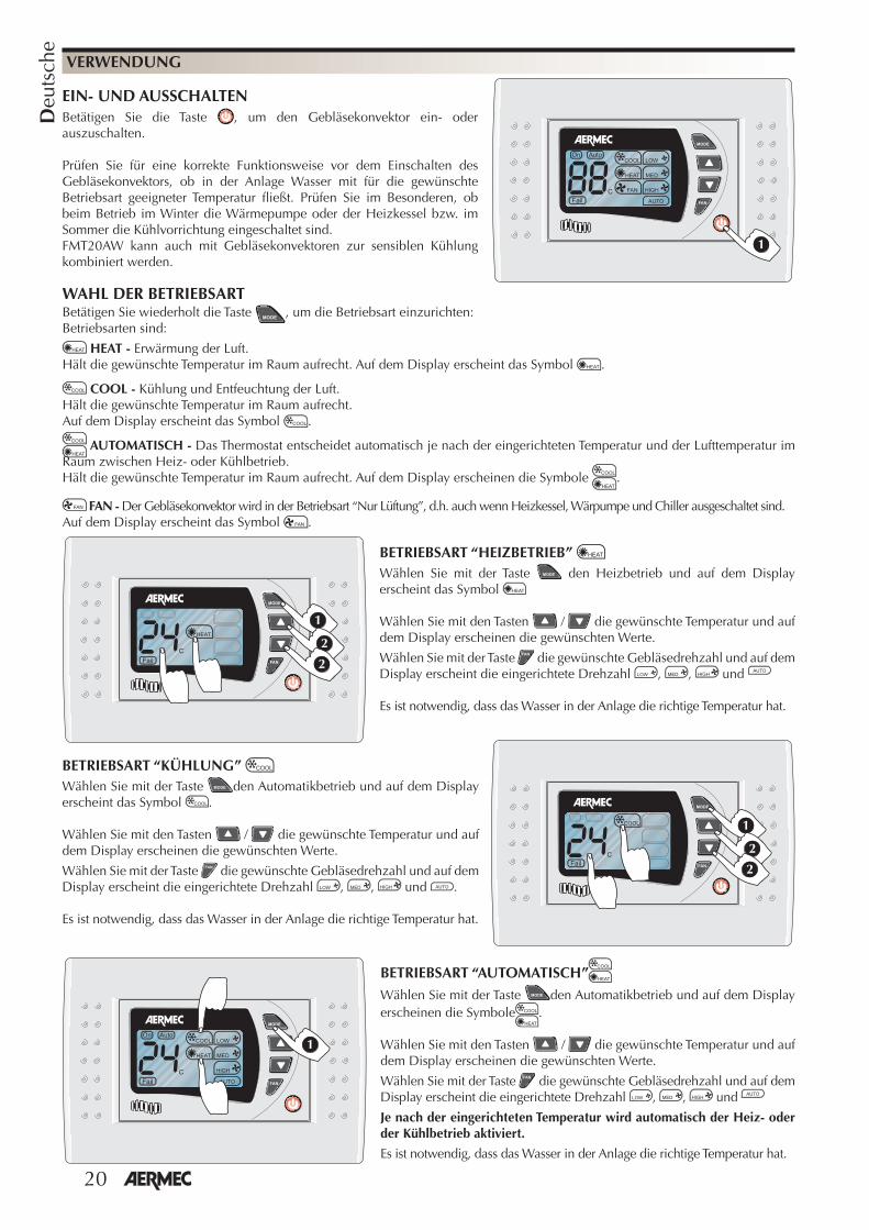
Betätigen Sie wiederholt die Taste , um die Betriebsart einzurichten: Betriebsarten sind:
HEAT - Erwärmung der Luft. Hält die gewünschte Temperatur im Raum aufrecht. Auf dem Display erscheint das Symbol .
COOL - Kühlung und Entfeuchtung der Luft. Hält die gewünschte Temperatur im Raum aufrecht. Auf dem Display erscheint das Symbol .
AUTOMATISCH - Das Thermostat entscheidet automatisch je nach der eingerichteten Temperatur und der Lufttemperatur im Raum zwischen Heiz- oder Kühlbetrieb. Hält die gewünschte Temperatur im Raum aufrecht. Auf dem Display erscheinen die Symbole .
FAN - Der Gebläsekonvektor wird in der Betriebsart “Nur Lüftung”, d.h. auch wenn Heizkessel, Wärpumpe und Chiller ausgeschaltet sind.Auf dem Display erscheint das Symbol .
VERWENDUNG
EIN- UND AUSSCHALTENBetätigen Sie die Taste , um den Gebläsekonvektor ein- oder auszuschalten.
Prüfen Sie für eine korrekte Funktionsweise vor dem Einschalten des Gebläsekonvektors, ob in der Anlage Wasser mit für die gewünschte Betriebsart geeigneter Temperatur fl ießt. Prüfen Sie im Besonderen, ob beim Betrieb im Winter die Wärmepumpe oder der Heizkessel bzw. im Sommer die Kühlvorrichtung eingeschaltet sind. FMT20AW kann auch mit Gebläsekonvektoren zur sensiblen Kühlung kombiniert werden.
�
BETRIEBSART “AUTOMATISCH”Wählen Sie mit der Taste den Automatikbetrieb und auf dem Display erscheinen die Symbole .
Wählen Sie mit den Tasten / die gewünschte Temperatur und auf dem Display erscheinen die gewünschten Werte.
Wählen Sie mit der Taste die gewünschte Gebläsedrehzahl und auf dem Display erscheint die eingerichtete Drehzahl , , und
Je nach der eingerichteten Temperatur wird automatisch der Heiz- oder der Kühlbetrieb aktiviert.
Es ist notwendig, dass das Wasser in der Anlage die richtige Temperatur hat.
WAHL DER BETRIEBSART
�
BETRIEBSART “HEIZBETRIEB” Wählen Sie mit der Taste den Heizbetrieb und auf dem Display erscheint das Symbol
Wählen Sie mit den Tasten / die gewünschte Temperatur und auf dem Display erscheinen die gewünschten Werte.
Wählen Sie mit der Taste die gewünschte Gebläsedrehzahl und auf dem Display erscheint die eingerichtete Drehzahl , , und
Es ist notwendig, dass das Wasser in der Anlage die richtige Temperatur hat.
�
�
�
�
�
�
BETRIEBSART “KÜHLUNG” Wählen Sie mit der Taste den Automatikbetrieb und auf dem Display erscheint das Symbol .
Wählen Sie mit den Tasten / die gewünschte Temperatur und auf dem Display erscheinen die gewünschten Werte.
Wählen Sie mit der Taste die gewünschte Gebläsedrehzahl und auf dem Display erscheint die eingerichtete Drehzahl , , und .
Es ist notwendig, dass das Wasser in der Anlage die richtige Temperatur hat.
21
Deu
tsch
e
VERWENDUNG
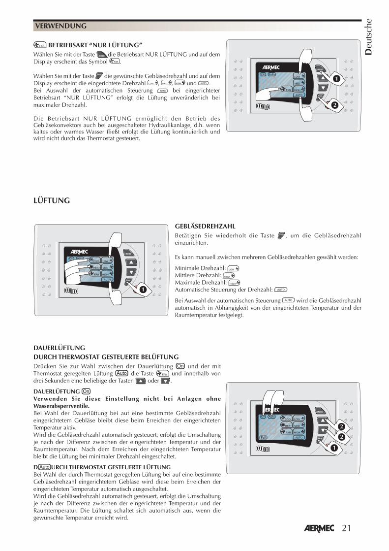
BETRIEBSART “NUR LÜFTUNG”Wählen Sie mit der Taste die Betriebsart NUR LÜFTUNG und auf dem Display erscheint das Symbol .
Wählen Sie mit der Taste die gewünschte Gebläsedrehzahl und auf dem Display erscheint die eingerichtete Drehzahl , , und .Bei Auswahl der automatischen Steuerung bei eingerichteter Betriebsart “NUR LÜFTUNG” erfolgt die Lüftung unveränderlich bei maximaler Drehzahl.
Die Betriebsart NUR LÜFTUNG ermöglicht den Betrieb des Gebläsekonvektors auch bei ausgeschalteter Hydraulikanlage, d.h. wenn kaltes oder warmes Wasser fließt erfolgt die Lüftung kontinuierlich und wird nicht durch das Thermostat gesteuert.
�
�
GEBLÄSEDREHZAHLBetätigen Sie wiederholt die Taste , um die Gebläsedrehzahl einzurichten.
Es kann manuell zwischen mehreren Gebläsedrehzahlen gewählt werden:
Minimale Drehzahl: Mittlere Drehzahl: Maximale Drehzahl: Automatische Steuerung der Drehzahl:
Bei Auswahl der automatischen Steuerung wird die Gebläsedrehzahl automatisch in Abhängigkeit von der eingerichteten Temperatur und der Raumtemperatur festgelegt.
�
LÜFTUNG
DAUERLÜFTUNGDURCH THERMOSTAT GESTEUERTE BELÜFTUNGDrücken Sie zur Wahl zwischen der Dauerlüftung und der mit Thermostat geregelten Lüftung die Taste und innerhalb von drei Sekunden eine beliebige der Tasten oder .
DAUERLÜFTUNG Verwenden Sie diese Einstel lung nicht bei Anlagen ohne Wasserabsperrventile.Bei Wahl der Dauerlüftung bei auf eine bestimmte Gebläsedrehzahl eingerichtetem Gebläse bleibt diese beim Erreichen der eingerichteten Temperatur aktiv. Wird die Gebläsedrehzahl automatisch gesteuert, erfolgt die Umschaltung je nach der Differenz zwischen der eingerichteten Temperatur und der Raumtemperatur. Nach dem Erreichen der eingerichteten Temperatur bleibt die Lüftung bei minimaler Drehzahl eingeschaltet.
D URCH THERMOSTAT GESTEUERTE LÜFTUNGBei Wahl der durch Thermostat geregelten Lüftung bei auf eine bestimmte Gebläsedrehzahl eingerichtetem Gebläse wird diese beim Erreichen der eingerichteten Temperatur automatisch ausgeschaltet. Wird die Gebläsedrehzahl automatisch gesteuert, erfolgt die Umschaltung je nach der Differenz zwischen der eingerichteten Temperatur und der Raumtemperatur. Die Lüftung schaltet sich automatisch aus, wenn die gewünschte Temperatur erreicht wird.
�
�
�
22
Deu
tsch
e
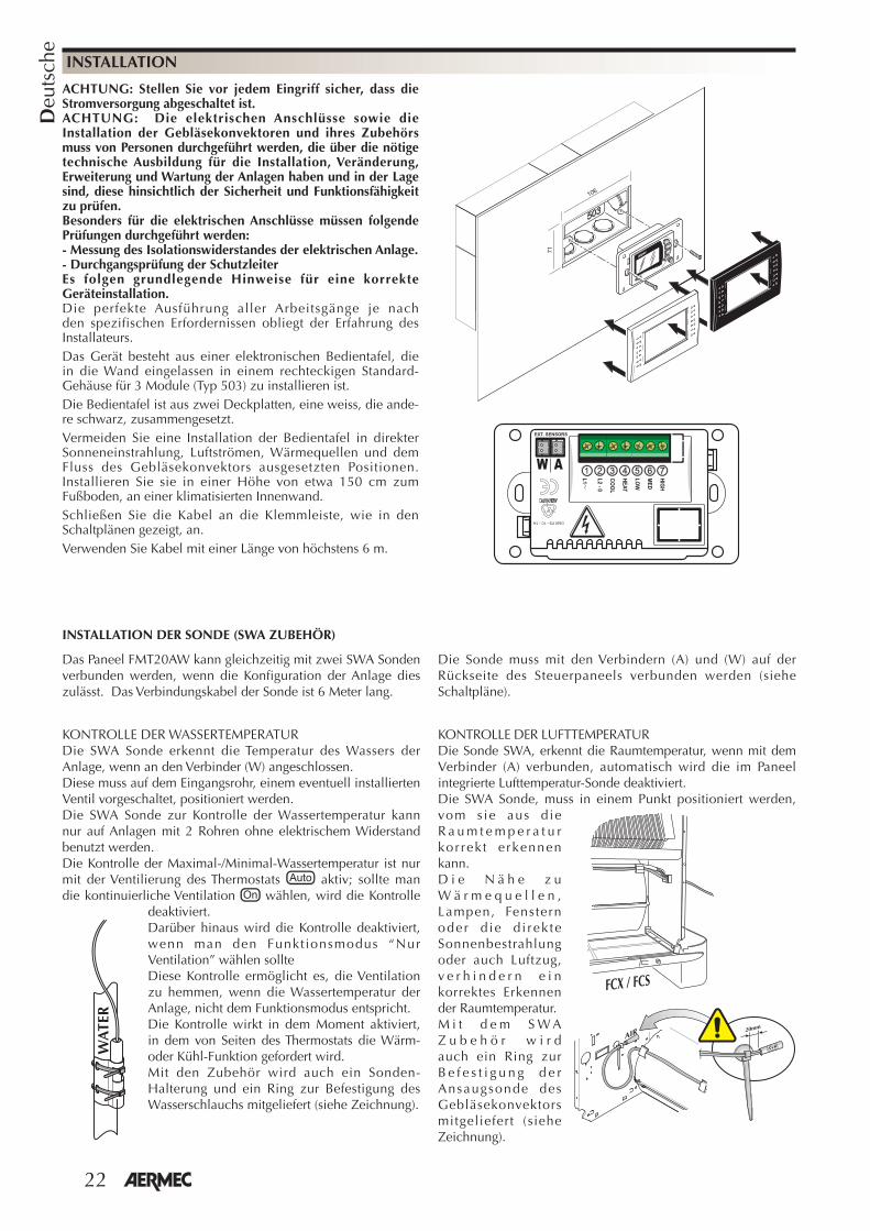
ACHTUNG: Stellen Sie vor jedem Eingriff sicher, dass die Stromversorgung abgeschaltet ist.ACHTUNG: Die elektrischen Anschlüsse sowie die Installation der Gebläsekonvektoren und ihres Zubehörs muss von Personen durchgeführt werden, die über die nötige technische Ausbildung für die Installation, Veränderung, Erweiterung und Wartung der Anlagen haben und in der Lage sind, diese hinsichtlich der Sicherheit und Funktionsfähigkeit zu prüfen. Besonders für die elektrischen Anschlüsse müssen folgende Prüfungen durchgeführt werden:- Messung des Isolationswiderstandes der elektrischen Anlage.- Durchgangsprüfung der SchutzleiterEs folgen grundlegende Hinweise für eine korrekte Geräteinstallation.Die perfekte Ausführung aller Arbeitsgänge je nach den spezifischen Erfordernissen obliegt der Erfahrung des Installateurs.Das Gerät besteht aus einer elektronischen Bedientafel, die in die Wand eingelassen in einem rechteckigen Standard-Gehäuse für 3 Module (Typ 503) zu installieren ist.Die Bedientafel ist aus zwei Deckplatten, eine weiss, die ande-re schwarz, zusammengesetzt.Vermeiden Sie eine Installation der Bedientafel in direkter Sonneneinstrahlung, Luftströmen, Wärmequellen und dem Fluss des Gebläsekonvektors ausgesetzten Positionen. Installieren Sie sie in einer Höhe von etwa 150 cm zum Fußboden, an einer klimatisierten Innenwand.Schließen Sie die Kabel an die Klemmleiste, wie in den Schaltplänen gezeigt, an.Verwenden Sie Kabel mit einer Länge von höchstens 6 m.
INSTALLATION
106
71
���
���
�
��
��
���
�
�
������
�������������
�� ��������
��
INSTALLATION DER SONDE (SWA ZUBEHÖR)
Das Paneel FMT20AW kann gleichzeitig mit zwei SWA Sonden verbunden werden, wenn die Konfiguration der Anlage dies zulässt. Das Verbindungskabel der Sonde ist 6 Meter lang.
Die Sonde muss mit den Verbindern (A) und (W) auf der Rückseite des Steuerpaneels verbunden werden (siehe Schaltpläne).
KONTROLLE DER WASSERTEMPERATURDie SWA Sonde erkennt die Temperatur des Wassers der Anlage, wenn an den Verbinder (W) angeschlossen.Diese muss auf dem Eingangsrohr, einem eventuell installierten Ventil vorgeschaltet, positioniert werden. Die SWA Sonde zur Kontrolle der Wassertemperatur kann nur auf Anlagen mit 2 Rohren ohne elektrischem Widerstand benutzt werden.Die Kontrolle der Maximal-/Minimal-Wassertemperatur ist nur mit der Ventilierung des Thermostats aktiv; sollte man die kontinuierliche Ventilation wählen, wird die Kontrolle
deaktiviert.Darüber hinaus wird die Kontrolle deaktiviert, wenn man den Funkt ionsmodus “Nur Ventilation” wählen sollteDiese Kontrolle ermöglicht es, die Ventilation zu hemmen, wenn die Wassertemperatur der Anlage, nicht dem Funktionsmodus entspricht. Die Kontrolle wirkt in dem Moment aktiviert, in dem von Seiten des Thermostats die Wärm- oder Kühl-Funktion gefordert wird. Mit den Zubehör wird auch ein Sonden-Halterung und ein Ring zur Befestigung des Wasserschlauchs mitgeliefert (siehe Zeichnung).
KONTROLLE DER LUFTTEMPERATURDie Sonde SWA, erkennt die Raumtemperatur, wenn mit dem Verbinder (A) verbunden, automatisch wird die im Paneel integrierte Lufttemperatur-Sonde deaktiviert.Die SWA Sonde, muss in einem Punkt positioniert werden, vom s ie aus d ie R a u m t e m p e r a t u r kor rek t e rkennen kann. D i e N ä h e z u W ä r m e q u e l l e n , Lampen, Fenstern oder d ie d i rek te Sonnenbestrahlung oder auch Luftzug, v e r h i n d e r n e i n korrektes Erkennen der Raumtemperatur.M i t d e m S W A Z u b e h ö r w i r d auch ein Ring zur B e f e s t i g u n g d e r Ansaugsonde des Gebläsekonvektors mitgeliefert (siehe Zeichnung).
� ��� ��� ��
����
�� ��
���
WA
TER
23
Espa
ñol
¡Enhorabuena por haber comprado el tablero de mandos con termostato electrónico FMT20AW Aermec! Al haber sido fabricado con materiales de calidad superior en total conformidad con las normativas de seguridad, “FMT20AW” es un aparato de fácil manejo que usted disfrutará durante mucho tiempo.
FUNCIONESEl termostato mantiene en la habitación la temperatura programada.
El tablero de mandos FMT20AW está dotado de las siguientes funciones:
- Selección del modo de funcionamiento A u t o m á t i c o , C a l e n t a m i e n t o , Refrigeración, sólo Ventilación.
- Cambio de estación manual.- Cambio estación automático lado aire.- Control de la temperatura mínima del
agua (calentamiento) y de la temperatura máxima del agua (enfriamiento) mediante el accesorio SWA, para instalaciones de 2 tubos sin resistencia. Con este accesorio, la ventilación se inhibe si la temperatura del agua de la instalación no es adecuada al modo de funcionamiento, garantizando así comodidad y ahorro energético.
- Selección manual de la velocidad de ventilación;
- Selección automática de la velocidad de ventilación en función de la temperatura ambiente;
- Ventilación controlada por termostato; - Ventilación continua; - Modo de funcionamiento de solo
ventilación.- Visualiza la temperatura configurada;- visualiza la velocidad de ventilación
configurada;- visualiza el modo de funcionamiento
en calentamiento;- visualiza el modo de funcionamiento
en refrigeración;- visualiza el modo de funcionamiento
en automático;- en el momento del encendido, el fan
coil se pone en marcha manteniendo las programaciones que estaban activas antes del apagado anterior;
- después de un corte de tensión, se vuelve a poner en marcha manteniendo
las programaciones que estaban activas antes de apagarse;
- sonda de la temperatura del aire incorporada en el tablero;
- Accesorio sonda externa SWA (longitud L = 6 m). Si se conecta al conector (A), detecta la temperatura del aire ambiente, y automáticamente se deshabilita la sonda de la temperatura del aire ambiente incorporada en el panel. Si está conectada al conector (W), detecta la temperatura del agua de la instalación para el permiso a la ventilación. En el panel FMT20AW se pueden conectar simultáneamente 2 sondas SWA.
VENTILACIÓNControl de la ventilación de tres velocidades, seleccionables manualmente o bien de forma automática.La velocidad de ventilación se configura utilizando el botón del termostato.Gestión manual, el ventilador utiliza ciclos de On-Off en la velocidad seleccionada.Gestión automática, visualización
, la velocidad del ventilador está gestionada por el microprocesador.La gestión automática de la velocidad está activa en los modos refrigeración, calentamiento y automático. El tiempo mínimo de funcionamiento entre una velocidad y la otra es de 30 segundos.Modo “SOLO VENTILACIÓN” El Modo SOLO VENTILACIÓN permite que el fan coil funcione incluso con la instalación hidráulica apagada, si circulara agua fría o caliente la ventilación será continua y no controlada por el termostato.
VENTILACIÓN CONTINUA La ventilación permanece activa pese a haberse alcanzado la temperatura programada; el control de la temperatura se realiza pues mediante la apertura y el cierre de la/las válvula/s de agua de la instalación.
No utilice esta configuración en las instalaciones sin válvulas de interceptación del agua ya que la ventilación será continua y no controlada por el termostato.
VENTILACIÓN CON TERMOSTATO L a v e n t i l a c i ó n s e d e t i e n e automát icamente a l a lcanzar la temperatura programada.
C o n t ro l d e M Í N I M A / M Á X I M A temperatura del agua (Tw) con accesorio SWA (para ventilación con termostato)
Si e l agua no es apta para e l funcionamiento, en el display parpadeará lentamente el icono .
�������� ���������
� �
�����
Tw = Temperatura aguaTa = Temperatura aire
ALARMAS:
Si Tw<1°C o Tw>80°C aparece el icono . El termostato continua trabajando
sin efectuar el control del agua.
Si Ta<5°C o Ta>40°C en el display parpadeará rápidamente el icono , el termostato cierra la/las válvulas y apaga la ventilación.
CHANGE OVER AUTOMÁTICO LADO AIREFunción activa sólo en el Modo AUTOMÁTICO .E l con t ro l pe rm i t e e s t ab i l i z a r a u t o m á t i c a m e n t e e l m o d o d e funcionamiento del ventilconvector en Calentamiento o en Enfriamiento, en función de la temperatura configurada y la temperatura ambiente detectada por la sonda de aire.
El termostato de regulación FMT20AW es un tablero de mandos para fan coils, para instalaciones de pared.Controla el funcionamiento del fan coil en función de la modalidad configurada y de la temperatura ambiente para mantener la temperatura deseada.Los tableros deben montarse en la pared; deben utilizarse en instalaciones de 4 tubos, de 2 tubos y de 2 tubos con resistencia, con la posibilidad de conectar dos válvulas de tipo On - Off para la interceptación del agua de alimentación de las baterías.Cada tablero de mandos sólo puede controlar un fan coil.El tablero de mandos está formado únicamente por circuitos eléctricos conectados a una tensión de red de
230V 50Hz; por esta razón, todas las entradas para las sondas y mandos deben ser aisladas para esta tensión.Los servomandos de las válvulas deben adaptarse para 230V 50Hz.FMT20AW puede ser instalado sólo por personal especializado.Quite la tensión de alimentación antes de iniciar cualquier actividad de instalación o mantenimiento. El contacto con los componentes bajo tensión puede provocar una peligrosa descarga eléctrica.
ESPECIFICACIONES TÉCNICAS:
Alimentación eléctrica: 230 V (± 10 %)Potencia absorbida: 1.5 VARango de temperaturas modificables: 10°C ÷ 30°C
Diferencial: ±0.5°CC o n d i c i o n e s a m b i e n t a l e s d e funcionamiento: 0°C ÷ 60°C con humedad relativa 10 % ÷ 90 %, sin condensación.C o n d i c i o n e s a m b i e n t a l e s d e almacenamiento: -18°C ÷ 60°C con humedad relativa 10% ÷ 90%, sin condensación.Material: ABS UL94 V0Color: RAL 9016Conforme a:Directivas LVD 2006/95/CE(EN 60730-1, EN 60730-2-9, EN 60335-1);Compatibi l idad electromagnética 2004/108/CE (EN 55011, 55022, 55014) ITS UL873.
Ventilación Ventilación
Enfriamiento Calentamiento
24
Espa
ñol
USO
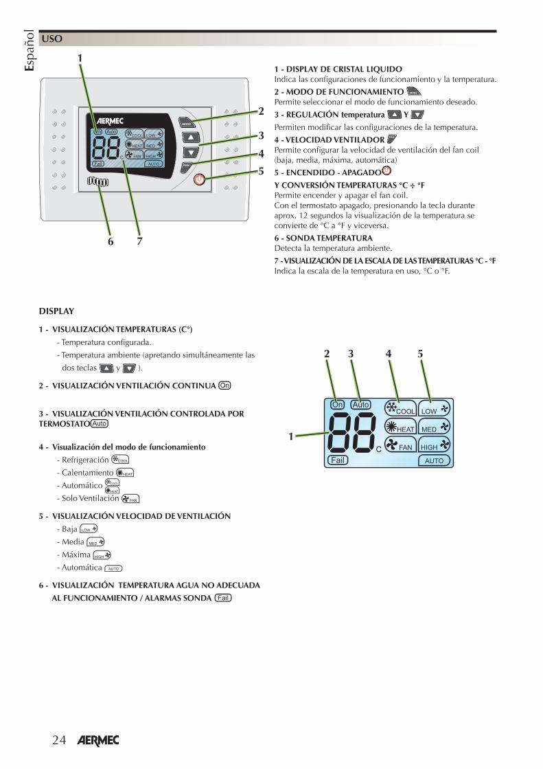
1 - DISPLAY DE CRISTAL LIQUIDOIndica las confi guraciones de funcionamiento y la temperatura.
2 - MODO DE FUNCIONAMIENTO Permite seleccionar el modo de funcionamiento deseado.
3 - REGULACIÓN temperatura Y
Permiten modifi car las confi guraciones de la temperatura.
4 - VELOCIDAD VENTILADOR Permite confi gurar la velocidad de ventilación del fan coil (baja, media, máxima, automática)
5 - ENCENDIDO - APAGADO
Y CONVERSIÓN TEMPERATURAS °C ÷ °FPermite encender y apagar el fan coil.Con el termostato apagado, presionando la tecla durante aprox. 12 segundos la visualización de la temperatura se convierte de °C a °F y viceversa.
6 - SONDA TEMPERATURA Detecta la temperatura ambiente.
7 - VISUALIZACIÓN DE LA ESCALA DE LAS TEMPERATURAS °C - °FIndica la escala de la temperatura en uso, °C o °F.
DISPLAY
1 - VISUALIZACIÓN TEMPERATURAS (C°)
- Temperatura confi gurada.
- Temperatura ambiente (apretando simultáneamente las
dos teclas y ).
2 - VISUALIZACIÓN VENTILACIÓN CONTINUA
3 - VISUALIZACIÓN VENTILACIÓN CONTROLADA POR TERMOSTATO
4 - Visualización del modo de funcionamiento
- Refrigeración
- Calentamiento
- Automático
- Solo Ventilación
5 - VISUALIZACIÓN VELOCIDAD DE VENTILACIÓN
- Baja
- Media
- Máxima
- Automática
6 - VISUALIZACIÓN TEMPERATURA AGUA NO ADECUADA
AL FUNCIONAMIENTO / ALARMAS SONDA
1
2 543
2
1
4
3
5
6 7
25
Espa
ñol
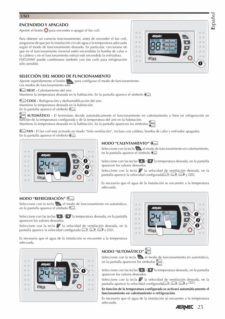
Apriete repetidamente el botón para confi gurar el modo de funcionamiento: Los modos de funcionamiento son:
HEAT - Calentamiento del aire. Mantiene la temperatura deseada en la habitación. En la pantalla aparece el símbolo .
COOL - Refrigeración y deshumidifi cación del aire. Mantiene la temperatura deseada en la habitación. En la pantalla aparece el símbolo .
AUTOMÁTICO - El termostato decide automáticamente el funcionamiento en calentamiento o bien en refrigeración en función de la temperatura confi gurada y de la temperatura del aire en la habitación. Mantiene la temperatura deseada en la habitación. En la pantalla aparecen los símbolos .
FAN - El fan coil está activado en modo “Solo ventilación”, incluso con caldera, bomba de calor y enfriador apagados.En la pantalla aparece el símbolo .
USO
ENCENDIDO Y APAGADOApriete el botón para encender o apagar el fan coil.
Para obtener un correcto funcionamiento, antes de encender el fan coil, asegurarse de que por la instalación circule agua a la temperatura adecuada según el modo de funcionamiento deseado. En particular, cerciorarse de que en el funcionamiento invernal estén encendidas la bomba de calor o la caldera y en el funcionamiento estival esté encendida la enfriadora. FMT20AW puede combinarse también con fan coils para refrigeración sólo sensible. �
MODO “AUTOMÁTICO” Seleccione con la tecla el modo de funcionamiento en automático, en la pantalla aparecen los símbolos .
Seleccione con las teclas / la temperatura deseada, en la pantalla aparecen los valores deseados.
Seleccione con la tecla la velocidad de ventilación deseada, en la pantalla aparece la velocidad confi gurada , , e .
En función de la temperatura confi gurada se activará automáticamente el funcionamiento en calentamiento o refrigeración.
Es necesario que el agua de la instalación se encuentre a la temperatura adecuada.
SELECCIÓN DEL MODO DE FUNCIONAMIENTO
�
MODO “CALENTAMIENTO” Seleccione con la tecla el modo de funcionamiento en calentamiento, en la pantalla aparece el símbolo
Seleccione con las teclas / la temperatura deseada, en la pantalla aparecen los valores deseados.
Seleccione con la tecla la velocidad de ventilación deseada, en la pantalla aparece la velocidad confi gurada , , y .
Es necesario que el agua de la instalación se encuentre a la temperatura adecuada.
�
�
�
�
�
�
MODO “REFRIGERACIÓN” Seleccione con la tecla el modo de funcionamiento en automático, en la pantalla aparece el símbolo .
Seleccione con las teclas / la temperatura deseada, en la pantalla aparecen los valores deseados.
Seleccione con la tecla la velocidad de ventilación deseada, en la pantalla aparece la velocidad confi gurada , , y .
Es necesario que el agua de la instalación se encuentre a la temperatura adecuada.
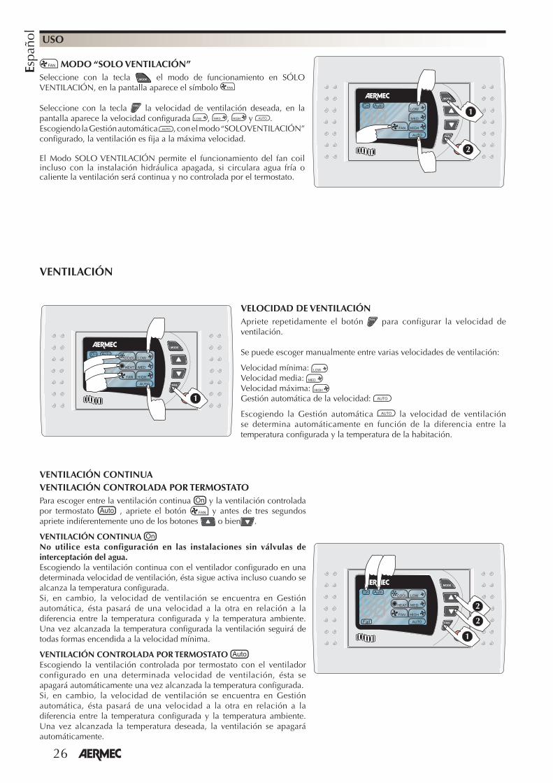
26
Espa
ñol
USO
MODO “SOLO VENTILACIÓN”Seleccione con la tecla el modo de funcionamiento en SÓLO VENTILACIÓN, en la pantalla aparece el símbolo
Seleccione con la tecla la velocidad de ventilación deseada, en la pantalla aparece la velocidad confi gurada , , y .Escogiendo la Gestión automática , con el modo “SOLO VENTILACIÓN” confi gurado, la ventilación es fi ja a la máxima velocidad.
El Modo SOLO VENTILACIÓN permite el funcionamiento del fan coil incluso con la instalación hidráulica apagada, si circulara agua fría o caliente la ventilación será continua y no controlada por el termostato.
�
�
VELOCIDAD DE VENTILACIÓNApriete repetidamente el botón para configurar la velocidad de ventilación.
Se puede escoger manualmente entre varias velocidades de ventilación:
Velocidad mínima: Velocidad media: Velocidad máxima: Gestión automática de la velocidad:
Escogiendo la Gestión automática la velocidad de ventilación se determina automáticamente en función de la diferencia entre la temperatura configurada y la temperatura de la habitación.
�
VENTILACIÓN
VENTILACIÓN CONTINUAVENTILACIÓN CONTROLADA POR TERMOSTATOPara escoger entre la ventilación continua y la ventilación controlada por termostato , apriete el botón y antes de tres segundos apriete indiferentemente uno de los botones o bien .
VENTILACIÓN CONTINUA No utilice esta configuración en las instalaciones sin válvulas de interceptación del agua.Escogiendo la ventilación continua con el ventilador configurado en una determinada velocidad de ventilación, ésta sigue activa incluso cuando se alcanza la temperatura configurada. Si, en cambio, la velocidad de ventilación se encuentra en Gestión automática, ésta pasará de una velocidad a la otra en relación a la diferencia entre la temperatura configurada y la temperatura ambiente. Una vez alcanzada la temperatura configurada la ventilación seguirá de todas formas encendida a la velocidad mínima.
VENTILACIÓN CONTROLADA POR TERMOSTATO Escogiendo la ventilación controlada por termostato con el ventilador configurado en una determinada velocidad de ventilación, ésta se apagará automáticamente una vez alcanzada la temperatura configurada. Si, en cambio, la velocidad de ventilación se encuentra en Gestión automática, ésta pasará de una velocidad a la otra en relación a la diferencia entre la temperatura configurada y la temperatura ambiente. Una vez alcanzada la temperatura deseada, la ventilación se apagará automáticamente.
�
�
�
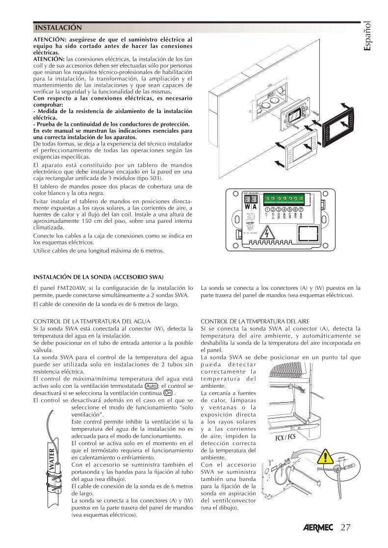
27
Espa
ñol
ATENCIÓN: asegúrese de que el suministro eléctrico al equipo ha sido cortado antes de hacer las conexiones eléctricas.ATENCIÓN: las conexiones eléctricas, la instalación de los fan coil y de sus accesorios deben ser efectuadas sólo por personas que reúnan los requisitos técnico-profesionales de habilitación para la instalación, la transformación, la ampliación y el mantenimiento de las instalaciones y que sean capaces de verificar la seguridad y la funcionalidad de las mismas. Con respecto a las conexiones eléctricas, es necesario comprobar:- Medida de la resistencia de aislamiento de la instalación eléctrica.- Prueba de la continuidad de los conductores de protección.En este manual se muestran las indicaciones esenciales para una correcta instalación de los aparatos.De todas formas, se deja a la experiencia del técnico instalador el perfeccionamiento de todas las operaciones según las exigencias específicas.El aparato está constituido por un tablero de mandos electrónico que debe instalarse encajado en la pared en una caja rectangular unificada de 3 módulos (tipo 503).El tablero de mandos posee dos placas de cobertura una de color blanco y la otra negra.Evitar instalar el tablero de mandos en posiciones directa-mente expuestas a los rayos solares, a las corrientes de aire, a fuentes de calor y al flujo del fan coil. Instale a una altura de aproximadamente 150 cm del piso, sobre una pared interna climatizada.Conecte los cables a la caja de conexiones como se indica en los esquemas eléctricos.Utilice cables de una longitud máxima de 6 metros.
INSTALACIÓN
106
71
���
���
�
��
��
���
�
�
������
�������������
�� ��������
��
INSTALACIÓN DE LA SONDA (ACCESORIO SWA)
El panel FMT20AW, si la configuración de la instalación lo permite, puede conectarse simultáneamente a 2 sondas SWA.
El cable de conexión de la sonda es de 6 metros de largo.
La sonda se conecta a los conectores (A) y (W) puestos en la parte trasera del panel de mandos (vea esquemas eléctricos).
CONTROL DE LA TEMPERATURA DEL AGUASi la sonda SWA está conectada al conector (W), detecta la temperatura del agua en la instalación.Se debe posicionar en el tubo de entrada anterior a la posible válvula.La sonda SWA para el control de la temperatura del agua puede ser utilizada solo en instalaciones de 2 tubos sin resistencia eléctrica.El control de máxima/mínima temperatura del agua está activo solo con la ventilación termostatada ; el control se desactivará si se selecciona la ventilación continua .El control se desactivará además en el caso en el que se
seleccione el modo de funcionamiento “solo ventilación”.Este control permite inhibir la ventilación si la temperatura del agua de la instalación no es adecuada para el modo de funcionamiento.El control se activa solo en el momento en el que el termóstato requiera el funcionamiento en calentamiento o enfriamiento.Con el accesorio se suministra también el portasonda y las bandas para la fijación al tubo del agua (vea dibujo).El cable de conexión de la sonda es de 6 metros de largo.La sonda se conecta a los conectores (A) y (W) puestos en la parte trasera del panel de mandos (vea esquemas eléctricos).
CONTROL DE LA TEMPERATURA DEL AIRESi se conecta la sonda SWA al conector (A), detecta la temperatura del aire ambiente, y automáticamente se deshabilita la sonda de la temperatura del aire incorporada en el panel.La sonda SWA se debe posicionar en un punto tal que p u e d a d e t e c t a r cor rec tamente la t e m p e r a t u r a d e l ambiente. La cercanía a fuentes de calor, lámparas y ven tanas o la exposición directa a los rayos solares y a las corrientes de aire, impiden la detección correcta de la temperatura del ambiente.Con el accesorio SWA se suministra también una banda para la fijación de la sonda en aspiración del ventilconvector (vea el dibujo).
� ��� ��� ��
����
�� ��
���
WA
TER
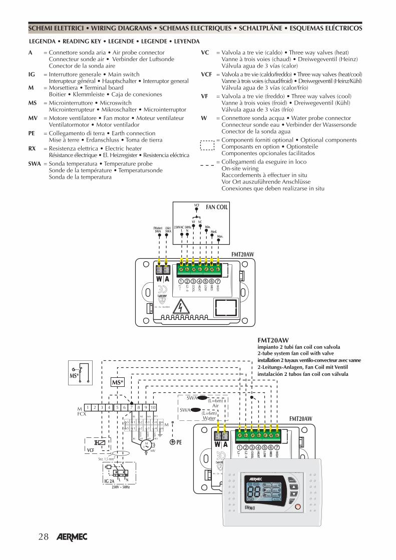
28
� �����������
��
� �
�
���
���
����
��
��
�����
�������������
�
������
������
������
������ �
��
������!��"#!��$�"#
LEGENDA • READING KEY • LEGENDE • LEGENDE • LEYENDA
A = Connettore sonda aria • Air probe connector Connecteur sonde air • Verbinder der Luftsonde Conector de la sonda aireIG = Interruttore generale • Main switch Interupteur général • Hauptschalter • Interruptor generalM = Morsettiera • Terminal board Boitier • Klemmleiste • Caja de conexionesMS = Microinterruttore • Microswitch Microinterrupteur • Mikroschalter • MicrointerruptorMV = Motore ventilatore • Fan motor • Moteur ventilateur Ventilatormotor • Motor ventiladorPE = Collegamento di terra • Earth connection Mise à terre • Erdanschluss • Toma de tierraRX = Resistenza elettrica • Electric heater Résistance électrique • El. Heizregister • Resistencia eléctrica SWA = Sonda temperatura • Temperature probe Sonde de la température • Temperatursonde Sonda de la temperatura
VC = Valvola a tre vie (caldo) • Three way valves (heat) Vanne à trois voies (chaud) • Dreiwegeventil (Heinz) Válvula agua de 3 vías (calor)VCF = Valvola a tre vie (caldo/freddo) • Three way valves (heat/cool) Vanne à trois voies (chaud/froid) • Dreiwegeventil (Heinz/Kühl) Válvula agua de 3 vías (calor/frío)VF = Valvola a tre vie (freddo) • Three way valves (cool) Vanne à trois voies (froid) • Dreiwegeventil (Kühl) Válvula agua de 3 vías (frío)W = Connettore sonda acqua • Water probe connector Connecteur sonde eau • Verbinder der Wassersonde Conector de la sonda agua
= Componenti forniti optional • Optional components Composants en option • Optionsteile Componentes opcionales facilitados = Collegamenti da eseguire in loco On-site wiring Raccordements à effectuer in situ
Vor Ort auszuführende Anschlüsse Conexiones que deben realizarse in situ
SCHEMI ELETTRICI • WIRING DIAGRAMS • SCHEMAS ELECTRIQUES • SCHALTPLÄNE • ESQUEMAS ELÉCTRICOS
���
���
�
��
��
���
�
�
������
�������������
������
��
� � � � � � � ��
%&
�'��� � �
�����(�����
� ����������
�
��)��)
����
��
�
� �
�
�
�
�
�
�
��
��
�� �� �� ��
�� �� �� ��
��
��
�
���
� �
�!�"�#��$!%& '
�!� "�#��$�('
FMT20AWimpianto 2 tubi fan coil con valvola2-tube system fan coil with valveinstallation 2 tuyaux ventilo-convecteur avec vanne2-Leitungs-Anlagen, Fan Coil mit Ventilinstalación 2 tubos fan coil con válvula
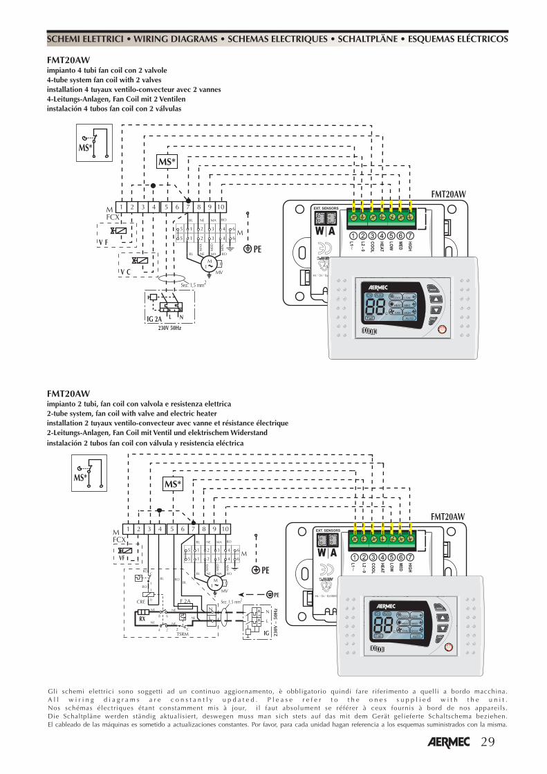
29
Gli schemi elettrici sono soggetti ad un continuo aggiornamento, è obbligatorio quindi fare riferimento a quelli a bordo macchina.A l l w i r i n g d i a g r a m s a r e c o n s t a n t l y u p d a t e d . P l e a s e r e f e r t o t h e o n e s s u p p l i e d w i t h t h e u n i t .Nos schémas électriques étant constamment mis à jour, i l faut absolument se référer à ceux fournis à bord de nos appareils.Die Schaltpläne werden ständig aktualisiert, deswegen muss man sich stets auf das mit dem Gerät gelieferte Schaltschema beziehen.El cableado de las máquinas es sometido a actualizaciones constantes. Por favor, para cada unidad hagan referencia a los esquemas suministrados con la misma.
���
���
�
��
��
���
�
�
������
�������������
�������� ��������
��
� � � � � � � ��
%&
�'��� � �
���������
� ����������
�
�
��)��)
����
��
�
� �
�
�
�
�
�
�
��
��
�� �� �� ��
�� �� �� ��
��
��
�
���
� �
FMT20AWimpianto 4 tubi fan coil con 2 valvole4-tube system fan coil with 2 valvesinstallation 4 tuyaux ventilo-convecteur avec 2 vannes4-Leitungs-Anlagen, Fan Coil mit 2 Ventileninstalación 4 tubos fan coil con 2 válvulas
SCHEMI ELETTRICI • WIRING DIAGRAMS • SCHEMAS ELECTRIQUES • SCHALTPLÄNE • ESQUEMAS ELÉCTRICOS
���
���
�
��
��
���
�
�
�������������������
�������� ��������
��
� � � � � � � ��
%&
��)��)
����
����
�(����
�
�
�
�
�
�
� �
�
�
�
�
�
�
��
�� �
�
����
�
� �
��
��
��
��
����
��
��
��
��
�
�'
%&� ����������
)���
���
��
�
�
�
�
��
�� �� �� ��
�� �� �� ��
��
��
�
���
� �
FMT20AWimpianto 2 tubi, fan coil con valvola e resistenza elettrica2-tube system, fan coil with valve and electric heaterinstallation 2 tuyaux ventilo-convecteur avec vanne et résistance électrique2-Leitungs-Anlagen, Fan Coil mit Ventil und elektrischem Widerstandinstalación 2 tubos fan coil con válvula y resistencia eléctrica
30

AERMEC S.p.A.I-37040 Bevilacqua (VR) - ItaliaVia Roma, 44 - Tel. (+39) 0442 633111Telefax (+39) 0442 93730 - (+39) 0442 93566www.aermec.com - [email protected]
I dati tecnici riportati nella presente documentazione non sono impegnativi.AERMEC S.p.A. si riserva la facoltà di apportare in qualsiasi momento tutte le modifiche ritenute necessarie per il miglioramento del prodotto.Les données mentionnées dans ce manuel ne constituent aucun engagement de notre part. Aermec S.p.A. se réserve le droit de modifier à tous moments les données considérées nécessaires à l’amelioration du produit.Technical data shown in this booklet are not binding.Aermec S.p.A. shall have the right to introduce at any time whatever modifications deemed necessary to the improvement of the product.Im Sinne des technischen Fortsschrittes behält sich Aermec S.p.A. vor, in der Produktion Änderungen und Verbesserungen ohne Ankündigung durchzuführen.Los datos técnicos indicados en la presente documentación no son vinculantes.Aermec S.p.A. se reserva el derecho de realizar en cualquier momento las modificaciones que estime necesarias para mejorar el producto.