ELECTROCHEMICAL REMEDIATION - bonifiche.provincia.tn.it · ELECTROCHEMICAL REMEDIATION Achille De...
26
ELECTROCHEMICAL REMEDIATION Achille De Battisti Dip. Biologia ed Evoluzione Dall’Emergenza delle Bonifiche ad Una Gestione Consapevole del Territorio Trento, 3-4 Luglio 2008 Provincia Autonoma di Trento Università degli Studi di Ferrara
Transcript of ELECTROCHEMICAL REMEDIATION - bonifiche.provincia.tn.it · ELECTROCHEMICAL REMEDIATION Achille De...

ELECTROCHEMICAL REMEDIATION
Achille De BattistiDip. Biologia ed Evoluzione
Dall’Emergenza delle Bonifiche ad Una GestioneConsapevole del Territorio
Trento, 3-4 Luglio 2008Provincia Autonoma di Trento
Universitàdegli Studidi Ferrara

Electrochemistry for enviromental remediation:
Non-destructive removal of pollutants from soils
- Detoxification/sterilization of industrial wastewaters, landfill leachates, swimming-pool water, water in food industry.
- Cold incineration of organic wastes and disgregation of radioactive residuals.
- Quality improvement of drinkable water, detoxification/sterilization of groundwaters

Methods:Imposition of potential gradients across the polluted soil polarizing suitably positioned electrodes
Soils: Electrochemical (electrokinetic) extraction of pollutants
Primary effects: displacement of charged species (electromigration, electro-osmosis), and neutral species (electro-osmosis).
Secondary effects: Accumulation of pollutants in electrodic spaces, followed by abatement.

Advantages: in situ methods, substantially non-destructive, no chemicals used, low energy consumption (e.g.: few tens of Volts and currents of the order of few Amperes); flexibility (e.g.: D.C. , A.C. polarization),
Disadvantages: possible incompatibility with the specific features of the site to be reclamated, problems of stability for metallic structures in the soil.
Soils: Electrochemical (electrokinetic) remediation

Electrokinetic phenomena: some general aspects
------------
+
+
+++
++++
+
++
+
φS
φ0
φ2
Outer HelmholtzPlane
Sharing plane
ζ
∆V

Further information on an electrified interphase
−= xe χφ φ 0
− =
∑
/
i i
RTF cz
εχπ
1 2
12 28
or−= xe χφ φ 2
φ = potential at the distance x from the charged wall
φ0= potential at the charged wall
φ2= potential at the Outer Helmholtz Plane (OHP)
ε = permittivity of the liquid phase
χ-1= diffuse-layer “thickness”
φ

Charge at the surface of an oxide particle

-
-
--
--
-
----
++
+ ++
+++
χ-1
surface of the immobile solid with charge density -qd
transit plane
−euη
χ 1
charge plane (qd)
ue

++
+
++ +
+++
+
+
+
++
+++
+
+ +
+
+++++
++
-
- -- -
--
--
-
--
-- -- -
----
---
--
--
+ + +-- -
- -
-
-
+
++-
--
--
+
++-
+
+ +
Semplified scheme of a particle plug with surface ionogenic groups: fixed solid-mobile solution
Hydrostatic pressure gradients across the plug, cause a displacement of a fraction of the volume-charge in the direction of the fluid flow. As a consequence, streaming currents and potentials are measured

Flow of electrolyte solutions through capillary channels with charged surface
Elettro-osmosis
Phenomenological equation
= +eu a P a E∆1 2ue=electro-osmotic velocity; ∆P=pressure gradient; E=electric field
Electrode
ElectrodeElectrolyte solution
Electro-osmotic flow
Electrode
ElectrodeElectrolyte solution
Electro-osmotic flow
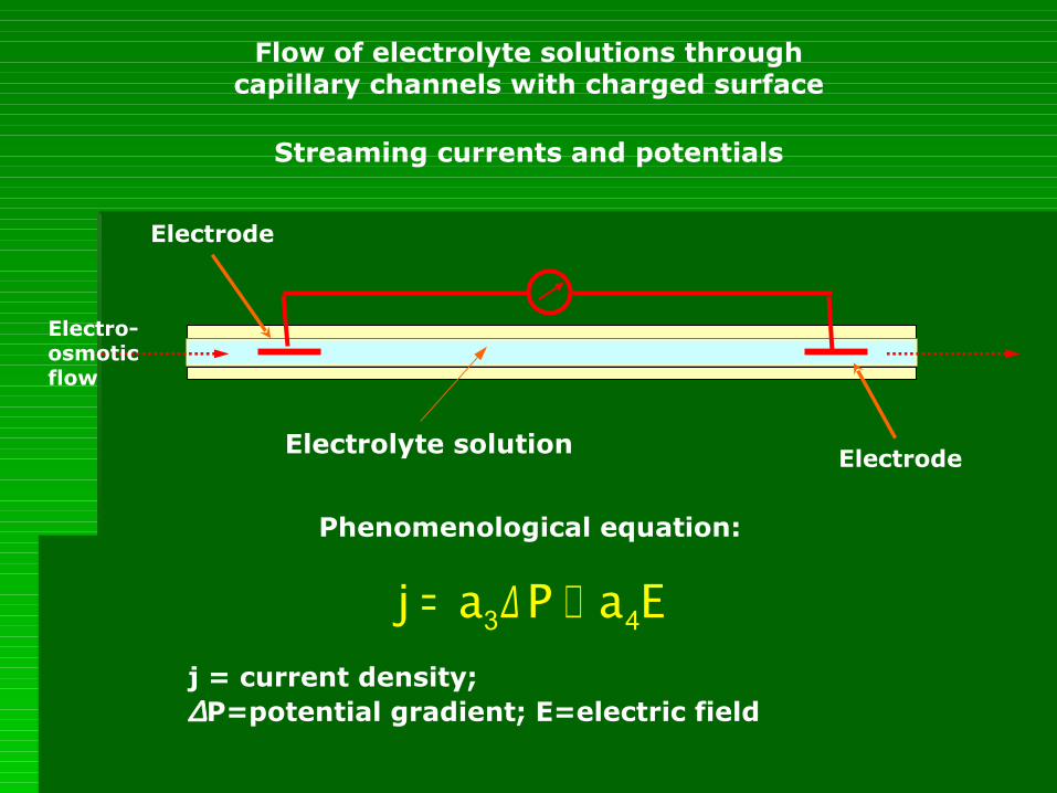
Flow of electrolyte solutions through capillary channels with charged surface
Streaming currents and potentials
Phenomenological equation:
= +j a P a E∆3 4
j = current density; ∆P=potential gradient; E=electric field
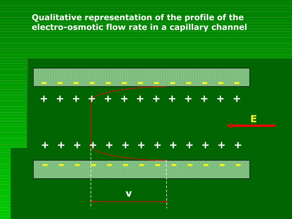
- - - - - - - - - - - - -
- - - - - - - - - - - - -
v
E
Qualitative representation of the profile of the electro-osmotic flow rate in a capillary channel
+ + ++ ++ ++ ++ + + +
+ + ++ ++ ++ ++ + + +

= =a a ε φη
02 3
= =a a ε ζη2 3
In the hypothesis that the shear plane and capillary surface cohincide:
From former definitions we have also:
−= =dqC εφ χ 1
0
−
= dqχφε
1
0

Transport due to the electric field: electro-osmosis
= −e ev k EAVe = electro-osmotic flow rateue = electro-osmotic velocityke = electro-osmotic permeability coefficientE = electric fieldA = total cross-sectional area
= −eEu ε ζ
η= −e
EAV ε ζη
=enk ε ζ
η τ 2
n = porosity
τ = tortuosity
In realtà le cose sono più complesse:
Some considerations on the electro-osmotic permeability coefficient
The electro-osmotic permeability coefficient, ke is independent from the pore diameter, at variance with the hydraulic permeability coefficient, kh.
The experimental values of ke do not depend on soil nature and change within a very narrow range, between 10-9 e 10-8 m2 V-1 s-1, while kh ranges between 10-13 e 10-5 m s-1.
An electric gradient is more effective than an hydraulic one in fine-grained soils.
Electro-osmotic flow is well controlled, being confined within the area across which electric field is active
Being ζ for a given soil negative, the electro-osmotic flow is addressed toward the cathode.

Transport under the effect of electrici field: electromigration
The dependence of ion elettromigrationOn potential gradient, in a capillary un:
=mu EνWhere um is the ion velocity, ν is the ionic mobility, assuming values typically around 3.10-8 m2 v-1 s-1 (about one order of magnitude higher for H+ e OH-
represent an exception).
Electromigration is affected by electric field, and ionic strength.
Soil chemistry, or soil-contaminant interaction:The kinetics of the removal of contaminants is bound to adsorption phenomena, ion-exchange, buffering capacity
Water content: inhomogeneous distribution of humidiy and consolidation may take place during an electrokinetic treatment
Soil structure: clogging of the soil porous texture and blocking of the electro-osmotic flow may take place due to hydroxide formation(presence of heavy metals)
Positioning of the electrodes and electrode structure: Solidity of the structure, easy workability, chemical stability, costs, are major actors. Silicon pig-iron, graphite, activated Titanium are electrode materials of practical interest.
Important factors in electrokinetic remediation

Optimization of the electro-osmotic process
-use of “washing” liquids , like water, diluite NaCl solutions.
-control of soil pH by means of buffering substances.
-washing of electrodic compartments, by addition of water/water solutions.
-addition of complexing agents, for heavy-metal removal
-weak alkalinization and/or addition of surfactants for the removal of strongly adsorbed organic contaminants
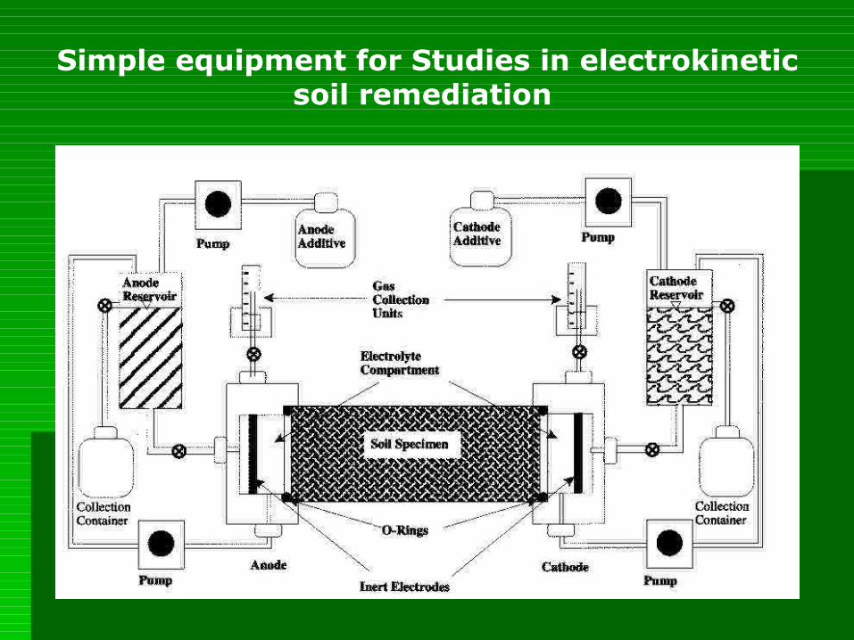
Simple equipment for Studies in electrokinetic soil remediation

Electrode distribution (bench scale to commercial installations

Electrode distribution (bench scale to commercial installations
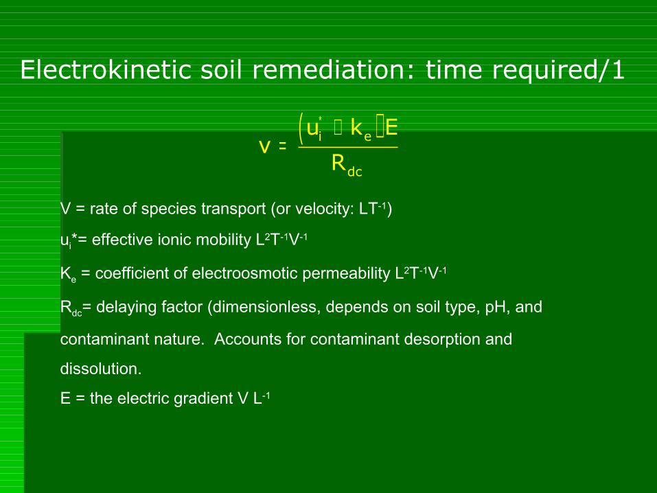
Electrokinetic soil remediation: time required/1
( )∗ += i e
dc
u k Ev
R
V = rate of species transport (or velocity: LT-1)
ui*= effective ionic mobility L2T-1V-1
Ke = coefficient of electroosmotic permeability L2T-1V-1
Rdc= delaying factor (dimensionless, depends on soil type, pH, and
contaminant nature. Accounts for contaminant desorption and
dissolution.
E = the electric gradient V L-1

Electrokinetic soil remediation: time required/2
∗=β σ
EE
L1T
E
The remediation time TE required for a given contaminant in a soil may be
expressed as: LE/v, where LE is the spacing between electrodes of opposite
polarity
σ* = effective soil conductivity (siemens m-1)
β is a lumped property of the contaminant and of the soil (L3 C-1), similar to
transference numbers in electrochemistry, but it also accounts for electroosmosis,
soil conditions and retardation caused by geochemical reactions:
( )∗
∗
+β =
σi e dcu k /R

Electrokinetic soil remediation: time required/3Electrokinetic soil remediation: time required/3
β is a fundamental parameter in electrokinetic soil remediation. Its values
typically range within 1.10-9 and 1.10-6 m3 C-1
If the remediation time has to be calculated on the basis of current density
applied across the soil, then we have:
EE
d
L1T
I=
β
Where Id is the electric current density = I/A (amp L-2), I is the total
current and A the cross-sectional area of the soil treated.

Electrokinetic soil remediation: the costs/1Electrokinetic soil remediation: the costs/1
The total cost of a full-scale in-situ implementation is the result of The total cost of a full-scale in-situ implementation is the result of
five componentsfive components2. Costs for fabrication and installation of electrodes3. Cost of electric energy4. Cost for enhancement agents (when necessary)5. Cost for post-treatments5. Fixed costs
•Costs for fabrication and installation of electrodes:Indicating with Celectrode (€ L-3) the electrode costs per unit volume
of soil, with C1 the electrode cost per unit length (€ L-1), with N
(L-2)the number of electrodes per unit surface, we have:
electrode 1C C N=C1 includes the cost of the electrode itself (materials, preparation),
drilling and preparation of the borehole, placing of elecrodes and other materials for installation (membranes, fabrics, etc.)
Electrokinetic soil remediation: the costs/2Electrokinetic soil remediation: the costs/2
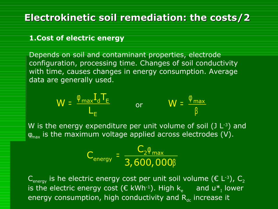
1.Cost of electric energy
Depends on soil and contaminant properties, electrode configuration, processing time. Changes of soil conductivity with time, causes changes in energy consumption. Average data are generally used.
max d E
E
I TW
Lφ
=
W is the energy expenditure per unit volume of soil (J L-3) and φmax is the maximum voltage applied across electrodes (V).
or maxWφ
=β
2 maxenergy
CC
3,600,000φ
=β
Cenergy is he electric energy cost per unit soil volume (€ L-3), C2 is the electric energy cost (€ kWh-1). High ke and u*I lower energy consumption, high conductivity and Rdc increase it