ELECTRO ADDA SpA · electro adda spa motori asincroni ... caratteristiche nominali e di...
36
ELECTRO ADDA SpA MOTORI ASINCRONI TRIFASI SERIE T 56 ÷ 160 kW 0.06 ÷ 18.5 ASYNCHRONOUS THREE-PHASE MOTORS T LINE 56 ÷ 160 kW 0.06 ÷ 18.5 CATALOGO SERIE T Tel.: 039/53.20.621 Fax: 039/53.21.335 E-mail: [email protected] www.electroadda.com REV. 03 10-05
Transcript of ELECTRO ADDA SpA · electro adda spa motori asincroni ... caratteristiche nominali e di...
ELECTRO ADDA SpA
MOTORI ASINCRONI TRIFASI
SERIE T 56 ÷ 160 kW 0.06 ÷ 18.5
ASYNCHRONOUS THREE-PHASE MOTORS
T LINE 56 ÷ 160 kW 0.06 ÷ 18.5
CATALOGO SERIE T
Tel.: 039/53.20.621 Fax: 039/53.21.335
E-mail: [email protected] www.electroadda.com
REV. 03 10-05
ELECTRO ADDA SpA
Costruzioni elettromeccaniche
Catalogo Electro Adda serie T - Rev. 03 10-05
2
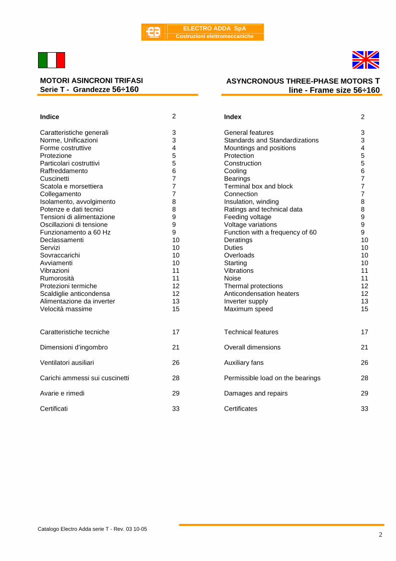
MOTORI ASINCRONI TRIFASI Serie T - Grandezze 56÷160
ASYNCRONOUS THREE-PHASE MOTORS T line - Frame size 56 ÷160
Indice 2 Index 2 Caratteristiche generali Norme, Unificazioni Forme costruttive Protezione Particolari costruttivi Raffreddamento Cuscinetti Scatola e morsettiera Collegamento Isolamento, avvolgimento Potenze e dati tecnici Tensioni di alimentazione Oscillazioni di tensione Funzionamento a 60 Hz Declassamenti Servizi Sovraccarichi Avviamenti Vibrazioni Rumorosità Protezioni termiche Scaldiglie anticondensa Alimentazione da inverter Velocità massime
3 3 4 5 5 6 7 7 7 8 8 9 9 9 10 10 10 10 11 11 12 12 13 15
General features Standards and Standardizations Mountings and positions Protection Construction Cooling Bearings Terminal box and block Connection Insulation, winding Ratings and technical data Feeding voltage Voltage variations Function with a frequency of 60 Deratings Duties Overloads Starting Vibrations Noise Thermal protections Anticondensation heaters Inverter supply Maximum speed
3 3 4 5 5 6 7 7 7 8 8 9 9 9 10 10 10 10 11 11 12 12 13 15
Caratteristiche tecniche
Dimensioni d’ingombro Ventilatori ausiliari Carichi ammessi sui cuscinetti Avarie e rimedi Certificati
17 21 26 28 29 33
Technical features Overall dimensions Auxiliary fans
Permissible load on the bearings Damages and repairs Certificates
17 21 26 28 29 33
ELECTRO ADDA SpA
Costruzioni elettromeccaniche
Catalogo Electro Adda serie T - Rev. 03 10-05
3
Caratteristiche generali General features
I motori della serie T con altezza d’asse da 56÷160, sono del tipo chiuso, con ventilazione esterna; hanno il rotore a gabbia.
The T line motors frame size 56÷160 are totally enclosed, fan cooled, with squirrel cage rotor.
Norme, Unificazioni Standards and standardizations
I motori serie T grandezze 56÷132 sono conformi alle seguenti Norme. CARATTERISTICHE NOMINALI E DI FUNZIONAMENTO - IEC 60034–1 CEI EN 60034-1 METODI DI DETERMINAZIONE DELLE PERDITE E DEL RENDIMENTO IEC 60034–2 CEI EN 60034–2 CLASSIFICAZIONE DEI GRADI DI PROTEZIONE (CODICE IP) IEC 60034–5 CEI EN 60034–5 METODI DI RAFFREDAMENTO (CODICE IC) IEC 60034-6 CEI EN 60034–6 CLASSIFICAZIONE FORME COSTRUTTIVE E TIPI DI INSTALLAZIONE (CODICE IM) IEC 60034-7 CEI EN 60034–7 MERCATURA DEI TERMINALI E SENSO DI ROTAZIONE IEC 60034-8 CEI 2-8 LIMITI DI RUMORE IEC 60034-9 CEI EN 60034–9 PROTEZIONI TERMICHE A BORDO MACCHINA IEC 60034-11 PRESTAZIONI ELETTRICHE DELLE MACCHINE ELETTRICHE ROTANTI ALL’AVVIAMENTO IEC 60034-12 CEI EN 60034–12 VIBRAZIONI MECCANICHE IEC 60034-14 CEI EN 60034–14 DIMENSIONI E POTENZE DELLE MACCHINE ELETTRICHE
CEI EN50347 IEC 60072-1 UNEL 13116 UNEL 13119
Le dimensioni di accoppiamento sono in accordo seguenti unificazioni: UNEL 13113-71 per la forma costruttiva B3, e per le forme
derivate. UNEL 13117- 71 per le forme costruttive B5, e per le
forme derivate Le unificazioni UNEL concordano con le norme internazionali IEC, pubblicazione 72, e relativo Amendment N0 1.
The T line motors frame size 56÷132 also comply with the following Standards: RATINGS AND PERFORMANCES IEC 60034-1 CEI EN 60034 - 1 METHODS FOR DETERMINING LOSSES AND EFFICIENCY IEC 60034 - 2 CEI EN 60034–2 CLASSIFICATION OF DEGREES OF PROTECTION (IP CODE) IEC 60034-5 CEI EN 60034–5 METHODS OF COOLING (IC CODE) IEC 60034 - 6 CEI EN 60034–6 CLASSIFICATION OF TYPE OF CONSTRUCTION AND MOUNTING ARRANGEMENTS (IM CODE) IEC 60034-7 CEI EN 60034–7 TERMINAL MARKINGS AND DIRECTION OF ROTATION IEC 60034-8 CEI 2-8 NOISE LIMITS IEC 60034-9 CEI EN 60034–9 BUILT-IN THERMAL PROTECTIONS IEC 60034-11 STARTING PERFORMANCE OF ROTATING ELECTRICAL MACHINES IEC 60034 – 12 CEI EN 60034 – 12 MECHANICAL VIBRATIONS IEC 60034-14 CEI EN 60034–14 DIMENSIONS AND OUTPUTS FOR ELECTRICAL MACHINES
CEI EN50347 IEC 60072-1 UNEL 13116 UNEL 13119
The coupling dimensions are in compliance with the following standardizations: UNEL 13113-71 for the B3 mounting and for other frame
shapes UNEL 13117–71 for the B5 mounting and for other frame
shapes The UNEL standardizations are in accordance with the IEC international standards publication 72 and relative Amendment Nr. 1.
ELECTRO ADDA SpA
Costruzioni elettromeccaniche
Catalogo Electro Adda serie T - Rev. 03 10-05
4
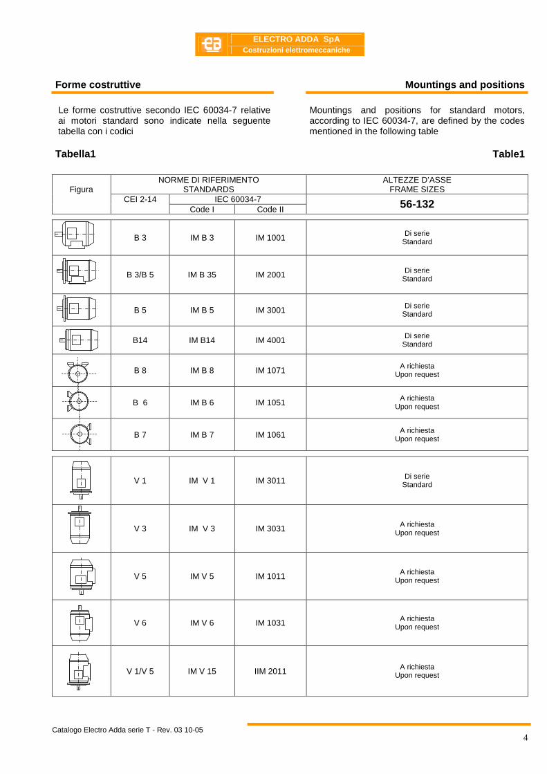
Forme costruttive Mountings and positions
Le forme costruttive secondo IEC 60034-7 relative ai motori standard sono indicate nella seguente tabella con i codici
Tabella1
Mountings and positions for standard motors, according to IEC 60034-7, are defined by the codes mentioned in the following table
Table1
NORME DI RIFERIMENTO STANDARDS
ALTEZZE D’ASSE FRAME SIZES
IEC 60034-7
Figura
CEI 2-14 Code I Code II 56-132
B 3 IM B 3 IM 1001 Di serie Standard
B 3/B 5 IM B 35 IM 2001 Di serie Standard
B 5 IM B 5 IM 3001 Di serie Standard
B14 IM B14 IM 4001 Di serie
Standard
B 8 IM B 8 IM 1071 A richiesta Upon request
B 6 IM B 6 IM 1051 A richiesta Upon request
B 7 IM B 7 IM 1061 A richiesta Upon request
V 1 IM V 1 IM 3011 Di serie Standard
V 3 IM V 3 IM 3031 A richiesta Upon request
V 5 IM V 5 IM 1011 A richiesta Upon request
V 6 IM V 6 IM 1031 A richiesta Upon request
V 1/V 5 IM V 15 IIM 2011 A richiesta
Upon request
ELECTRO ADDA SpA
Costruzioni elettromeccaniche
Catalogo Electro Adda serie T - Rev. 03 10-05
5
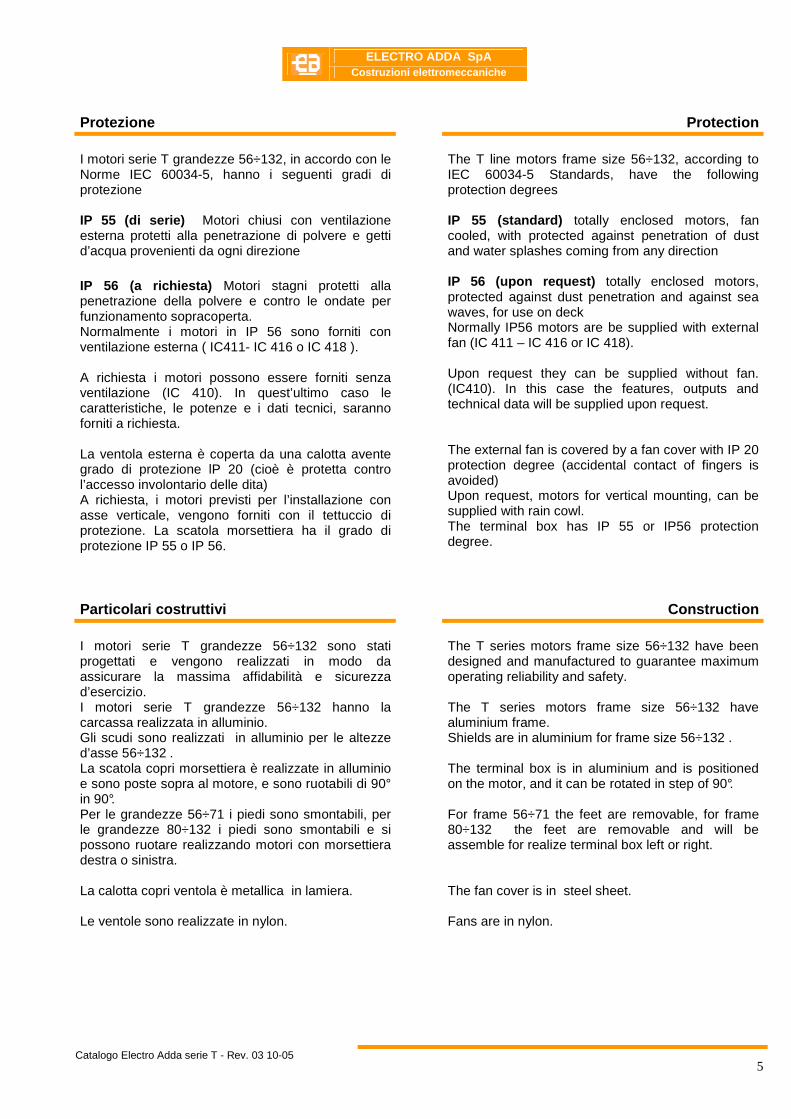
Protezione Protection
I motori serie T grandezze 56÷132, in accordo con le Norme IEC 60034-5, hanno i seguenti gradi di protezione IP 55 (di serie) Motori chiusi con ventilazione esterna protetti alla penetrazione di polvere e getti d’acqua provenienti da ogni direzione IP 56 (a richiesta) Motori stagni protetti alla penetrazione della polvere e contro le ondate per funzionamento sopracoperta. Normalmente i motori in IP 56 sono forniti con ventilazione esterna ( IC411- IC 416 o IC 418 ). A richiesta i motori possono essere forniti senza ventilazione (IC 410). In quest’ultimo caso le caratteristiche, le potenze e i dati tecnici, saranno forniti a richiesta. La ventola esterna è coperta da una calotta avente grado di protezione lP 20 (cioè è protetta contro l’accesso involontario delle dita) A richiesta, i motori previsti per l’installazione con asse verticale, vengono forniti con il tettuccio di protezione. La scatola morsettiera ha il grado di protezione IP 55 o IP 56.
The T line motors frame size 56÷132, according to IEC 60034-5 Standards, have the following protection degrees IP 55 (standard) totally enclosed motors, fan cooled, with protected against penetration of dust and water splashes coming from any direction IP 56 (upon request) totally enclosed motors, protected against dust penetration and against sea waves, for use on deck Normally IP56 motors are be supplied with external fan (IC 411 – IC 416 or IC 418). Upon request they can be supplied without fan. (IC410). In this case the features, outputs and technical data will be supplied upon request. The external fan is covered by a fan cover with IP 20 protection degree (accidental contact of fingers is avoided) Upon request, motors for vertical mounting, can be supplied with rain cowl. The terminal box has IP 55 or IP56 protection degree.
Particolari costruttivi Construction
I motori serie T grandezze 56÷132 sono stati progettati e vengono realizzati in modo da assicurare la massima affidabilità e sicurezza d’esercizio. I motori serie T grandezze 56÷132 hanno la carcassa realizzata in alluminio. Gli scudi sono realizzati in alluminio per le altezze d’asse 56÷132 . La scatola copri morsettiera è realizzate in alluminio e sono poste sopra al motore, e sono ruotabili di 90° in 90°. Per le grandezze 56÷71 i piedi sono smontabili, per le grandezze 80÷132 i piedi sono smontabili e si possono ruotare realizzando motori con morsettiera destra o sinistra. La calotta copri ventola è metallica in lamiera. Le ventole sono realizzate in nylon.
The T series motors frame size 56÷132 have been designed and manufactured to guarantee maximum operating reliability and safety. The T series motors frame size 56÷132 have aluminium frame. Shields are in aluminium for frame size 56÷132 . The terminal box is in aluminium and is positioned on the motor, and it can be rotated in step of 90°. For frame 56÷71 the feet are removable, for frame 80÷132 the feet are removable and will be assemble for realize terminal box left or right. The fan cover is in steel sheet. Fans are in nylon.

ELECTRO ADDA SpA
Costruzioni elettromeccaniche
Catalogo Electro Adda serie T - Rev. 03 10-05
6
Raffreddamento Cooling
La definizione del metodo di raffreddamento è data dal codice IC (International Cooling), in accordo alla IEC 60034-6
The designation of cooling method is given by the IC (International Cooling) code, according to IEC 60034-6
Codice I (Semplificato) IC __ __ __ Code I (Simplified) IC __ __ __ Disposizione del circuito
Circuit Arrangement
Metodi di circolazione del fluido di raffreddamento secondario.
Method of fluid circulation for the secondary cooling fluid.
Metodi di circolazione del fluido di raffreddamento primario.
Method of fluid circulation for the primary cooling fluid.
I motori in esecuzione standard di grandezza da 56 a 132 sono caratterizzati dal metodo di raffreddamento IC 411, con ventola radiale bidirezionale. Tutti i motori possono essere forniti con sistema di raffreddamento IC 416 su richiesta. In tal caso viene installato un opportuno ventilatore nel copriventola, opportunamente rinforzato, in modo da rendere la ventilazione indipendente dalla velocità di rotazione.
Motors in standard execution of frame sizes from 56 to 132 are supplied with IC 411 cooling systems, incorporating a bi-directional fan. All frame sizes can be supplied with cooling system IC 416 on request. In this case a proper fan is fitted inside the fan cover, suitably reinforced, in order to make the ventilation independent of the rotation speed.
Tabella 2 Table 2
Codice IC IC code Figura Descrizione Description
IC 411 Std
Motore autoventilato Macchina chiusa, alettata esternamente. Ventola esterna montata sull’albero del motore.
Self ventilating motor. Enclosed machine. Externally finned. External shaft-mounted fan.
IC 416 Su richiesta
Upon request
Motore con ventilazione assistita. Macchina chiusa, alettata esternamente. Ventilatore indipendente montato sotto copriventola.
Motor with assisted ventilation. Enclosed machine. Externally finned. Independent external fan mounted inside the fan cover.
IC 418
Su richiesta Upon request
Motore con ventilazione esterna. Macchina chiusa, alettata esternamente. Raffreddamento assicurato da un dispositivo non montato sul motore.
Motor with external ventilation. Enclosed machine. Externally finned. Ventilation provided by air flowing from the driven system.
IC 410 Su richiesta
Upon request
Motore con ventilazione naturale. Macchina chiusa,
Motor with natural ventilation Enclosed machine

ELECTRO ADDA SpA
Costruzioni elettromeccaniche
Catalogo Electro Adda serie T - Rev. 03 10-05
7
Caratteristiche cuscinetti Bearing specifications
I motori serie T hanno i cuscinetti a sfere. a gola profonda, lubrificati a grasso. In tutti i motori vengono montate e molle di precarico. per compensare il gioco assiale dei cuscinetti e per assorbire Ie vibrazioni Tutti i cuscinetti sono previsti per una durata di funzionamento (in base ai dati dei fabbricanti) di almeno 40.000 ore, con accoppiamento diretto Nella tabella 3 sono riportate tutte le caratteristiche relative ai cuscinetti installati sui motori grandezze 56÷132 serie T. Tabella 3
The T line motors frame size 56÷132 have deep groove, grease lubrificated ball bearings. Motor with bearing axial constrained have arrangement with spring in order to soak up vibration The lifetime of bearings ( in accordance with supplier data ) is in excess of 40.000 hours, for motors with direct coupling. In the table 3 are mentioned all specifications concerning bearings installed on motors frame size 56÷132 T series.
Table 3
Forma costruttiva B3 Frame B3
Forma costruttiva B5,B14 Frame B5,B14
Motore tipo
Motor Type
Poli
Poles
Cuscinetto lato accoppiamento
Bearing coupling side
Cuscinetto lato opposto accoppiamento
Bearing opposite coupling side
Cuscinetto lato accoppiamento.
Bearing coupling side
Cuscinetto lato opposto accoppiamento
Bearing opposite coupling side
56 2-4-6-8 6201-2Z 6201-2Z 6201-2Z 6201-2Z
63 2-4-6-8 6202-2Z 6202-2Z 6202-2Z 6202-2Z
71 2-4-6-8 6202-2Z 6202-2Z 6202-2Z 6202-2Z
80 2-4-6-8 6204-2Z 6204-2Z 6204-2Z 6204-2Z
90 2-4-6-8 6205-2Z 6205-2Z 6205-2Z 6205-2Z
100 2-4-6-8 6206-2Z 6206-2Z 6206-2Z 6206-2Z
112 2-4-6-8 6206-2Z 6206-2Z 6206-2Z 6206-2Z
132 2-4-6-8 6208-2Z C3 6208-2Z 6208-2Z C3 6208-2Z
Scatola e morsettiera Terminal box and block
La morsettiera è normalmente a sei morsetti. La basetta portamorsetti è di materiale antimuffa non igroscopico. Come detto, la scatola morsettiera ha il grado di protezione IP 55 di serie o IP 56, purché il collegamento dei cavi di alimentazione sia realizzato in modo adeguato.
The terminal board is normally equipped with 6 terminal, and is made with nonhygroscopic and anti-mold material. As just reported, the terminal box has IP 55 standard or IP56 protection degree, provided that the supply cable connections are properly made.
Collegamento Connection
I motori sono generalmente collegati a triangolo in modo da consentire l’avviamento stella-triangolo. A richiesta, e per applicazioni particolari, in funzione delle potenze e delle tensioni di alimentazione i motori possono essere collegati a stella.
Motors are usually delta connected to allow a star-delta starting. Upon request and for particular applications, based on the powers and supply voltages, motors can be star connected. , provided that the supply cable connections are properly made.
ELECTRO ADDA SpA
Costruzioni elettromeccaniche
Catalogo Electro Adda serie T - Rev. 03 10-05
8
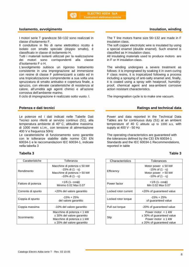
Isolamento, avvolgimento Insulation, winding
I motori serie T grandezze 56÷132 sono realizzati in classe d’isolamento F. Il conduttore in filo di rame elettrolitico ricotto è isolato con smalto speciale (doppio smalto), è classificato in classe di isolamento H. Tutti i materiali isolanti utilizzati per la realizzazione dei motori sono corrispondenti alla classe d’isolamento F o H. L’avvolgimento subisce un rigoroso trattamento consistente in una impregnazione ad immersione con resine di classe F polimerizzanti a caldo ed in una tropicalizzazione comprendente a sua volta una spruzzatura di smalto antisalso e copertura finale, a spruzzo, con elevate caratteristiche di resistenza al calore, all’umidità agli agenti chimici e all’azione corrosiva dell’ambiente marino. Il ciclo di impregnazione è realizzato sotto vuoto. I.
The T line motors frame size 56÷132 are made in F insulation class. The soft copper electrolytic wire is insulated by using a special enamel (double enamel). Such enamel is classified as H insulation class. All insulating materials used to produce motors are in F or H insulation class. The winding undergoes a severe treatment as follows: it is impregnated by soaking it in oven-curing F class resins, it is tropicalized following a process including a spraying of anti-salty enamel and, finally, it is coated using a spray with heatproof, humidity-proof, chemical agent and sea-ambient corrosive action resistant characteristics. The impregnation cycle is to make one vacuum.
Potenza e dati tecnici Ratings and technical data
Le potenze ed i dati indicati nelle Tabelle Dati Tecnici sono riferiti al servizio continuo (S1), alla temperatura ambiente di 40° C, altitudine massima di 1000 metri s.l.m., con tensione di alimentazione 400 V e frequenza 50Hz Le caratteristiche di funzionamento sono garantite con le tolleranze stabilite dalle norme CEI EN 60034-1 e le raccomandazioni IEC 60034-1, indicate nella tabella 3 Tabella 3
Power and data reported in the Technical Data Tables are for continuous duty (S1) at an ambient temperature of 40 C altitude up to 1000 a.s, with supply at 400 V - 50 Hz The operating characteristics are guaranteed with the tolerances defined by the CEI EN 60034-1 Standards and the IEC 60034-1 Recommendations, reported in table
Table 3
Caratteristiche Tolleranza Characteristics Tolerances
Rendimento
Macchine di potenza ≤ 50 kW -15% di (1 - η)
Macchine di potenza > 50 kW -10% di (1 - η)
Efficiency
Motor power ≤ 50 kW -15% of (1 - η)
Motor power > 50 kW -10% of (1 - η)
Fattore di potenza +1/6 (1- cosϕ) Minimo 0.02 Max 0.07
Power factor +1/6 (1- cosϕ) Min 0.02 Max 0.07
Corrente di spunto +20% del valore garantito Locked rotor current +20% of guaranteed value
Coppia di spunto -15% + 25% del valore garantito
Locked rotor torque -15% + 25% of guaranteed value
Coppia massima -10% del valore garantito Pull out torque -20% of guaranteed value
Scorrimento
Macchine di potenza < 1 kW ± 30% del valore garantito
Macchine di potenza ≥ 1 kW ± 20% del valore garantito
Slip
Power motor < 1 kW ± 30% of guaranteed value
Power motor ≥ 1 kW ± 20% of guaranteed value
ELECTRO ADDA SpA
Costruzioni elettromeccaniche
Catalogo Electro Adda serie T - Rev. 03 10-05
9
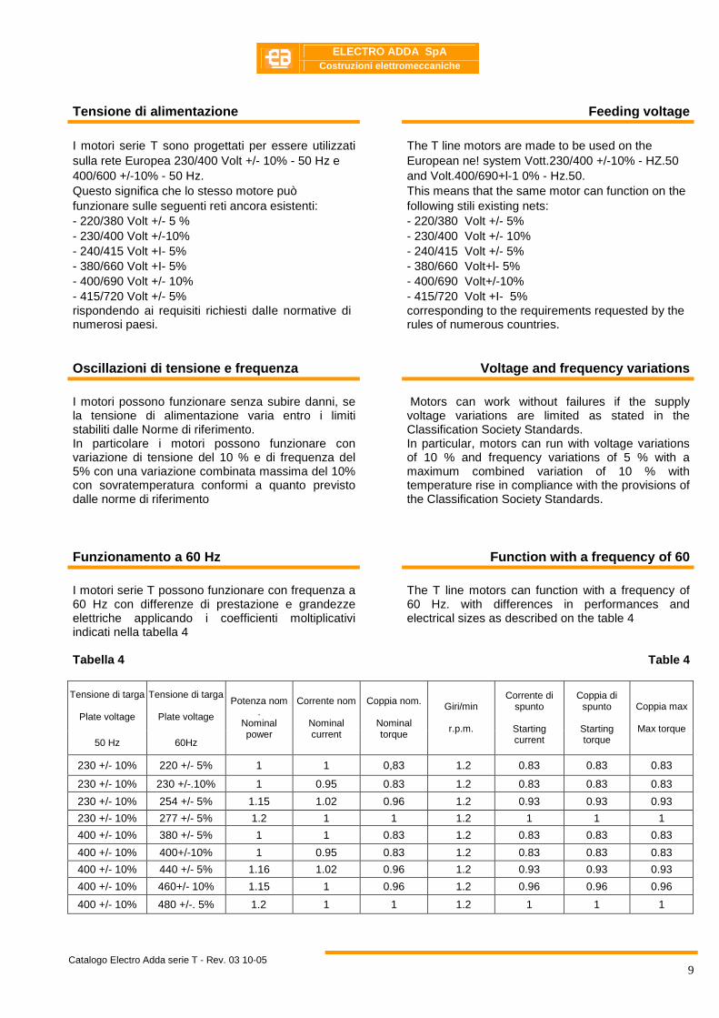
Tensione di alimentazione Feeding voltage
I motori serie T sono progettati per essere utilizzati sulla rete Europea 230/400 Volt +/- 10% - 50 Hz e 400/600 +/-10% - 50 Hz. Questo significa che lo stesso motore può funzionare sulle seguenti reti ancora esistenti: - 220/380 Volt +/- 5 % - 230/400 Volt +/-10% - 240/415 Volt +I- 5% - 380/660 Volt +I- 5% - 400/690 Volt +/- 10% - 415/720 Volt +/- 5% rispondendo ai requisiti richiesti dalIe normative di numerosi paesi.
The T line motors are made to be used on the European ne! system Vott.230/400 +/-10% - HZ.50 and Volt.400/690+l-1 0% - Hz.50. This means that the same motor can function on the following stili existing nets: - 220/380 Volt +/- 5% - 230/400 Volt +/- 10% - 240/415 Volt +/- 5% - 380/660 Volt+l- 5% - 400/690 Volt+/-10% - 415/720 Volt +I- 5% corresponding to the requirements requested by the rules of numerous countries.
Oscillazioni di tensione e frequenza Voltage and frequency variations
I motori possono funzionare senza subire danni, se la tensione di alimentazione varia entro i limiti stabiliti dalle Norme di riferimento. In particolare i motori possono funzionare con variazione di tensione del 10 % e di frequenza del 5% con una variazione combinata massima del 10% con sovratemperatura conformi a quanto previsto dalle norme di riferimento
Motors can work without failures if the supply voltage variations are limited as stated in the Classification Society Standards. In particular, motors can run with voltage variations of 10 % and frequency variations of 5 % with a maximum combined variation of 10 % with temperature rise in compliance with the provisions of the Classification Society Standards.
Funzionamento a 60 Hz Function with a frequency of 60
I motori serie T possono funzionare con frequenza a 60 Hz con differenze di prestazione e grandezze elettriche applicando i coefficienti moltiplicativi indicati nella tabella 4 Tabella 4
The T line motors can function with a frequency of 60 Hz. with differences in performances and electrical sizes as described on the table 4
Table 4
Tensione di targa
Plate voltage
Tensione di targa
Plate voltage 50 Hz 60Hz
Potenza nom .
Nominal power
Corrente nom
Nominal current
Coppia nom.
Nominal torque
Giri/min
r.p.m.
Corrente di spunto
Starting current
Coppia di spunto
Starting torque
Coppia max
Max torque
230 +/- 10% 220 +/- 5% 1 1 0,83 1.2 0.83 0.83 0.83
230 +/- 10% 230 +/-.10% 1 0.95 0.83 1.2 0.83 0.83 0.83
230 +/- 10% 254 +/- 5% 1.15 1.02 0.96 1.2 0.93 0.93 0.93
230 +/- 10% 277 +/- 5% 1.2 1 1 1.2 1 1 1
400 +/- 10% 380 +/- 5% 1 1 0.83 1.2 0.83 0.83 0.83
400 +/- 10% 400+/-10% 1 0.95 0.83 1.2 0.83 0.83 0.83
400 +/- 10% 440 +/- 5% 1.16 1.02 0.96 1.2 0.93 0.93 0.93
400 +/- 10% 460+/- 10% 1.15 1 0.96 1.2 0.96 0.96 0.96
400 +/- 10% 480 +/-. 5% 1.2 1 1 1.2 1 1 1
ELECTRO ADDA SpA
Costruzioni elettromeccaniche
Catalogo Electro Adda serie T - Rev. 03 10-05
10
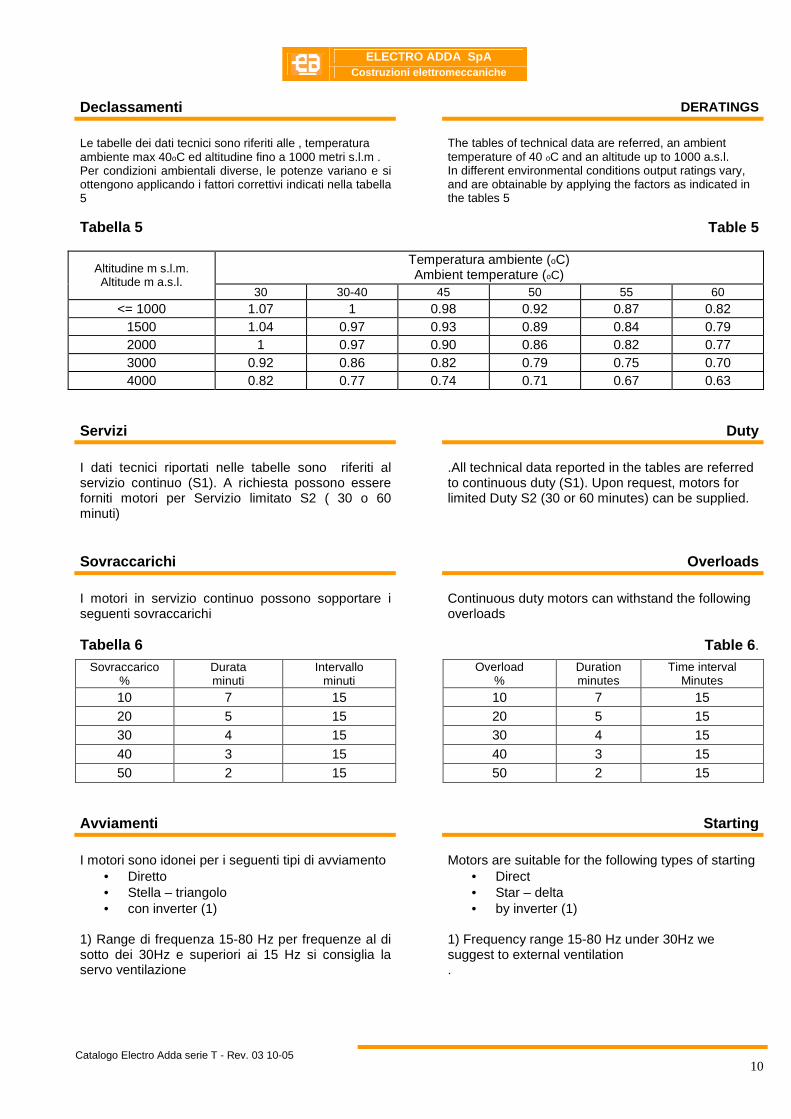
Declassamenti DERATINGS Le tabelle dei dati tecnici sono riferiti alle , temperatura ambiente max 40oC ed altitudine fino a 1000 metri s.l.m . Per condizioni ambientali diverse, le potenze variano e si ottengono applicando i fattori correttivi indicati nella tabella 5 Tabella 5
The tables of technical data are referred, an ambient temperature of 40 oC and an altitude up to 1000 a.s.l. In different environmental conditions output ratings vary, and are obtainable by applying the factors as indicated in the tables 5
Table 5
Temperatura ambiente (oC) Ambient temperature (oC) Altitudine m s.l.m.
Altitude m a.s.l. 30 30-40 45 50 55 60
<= 1000 1.07 1 0.98 0.92 0.87 0.82 1500 1.04 0.97 0.93 0.89 0.84 0.79 2000 1 0.97 0.90 0.86 0.82 0.77 3000 0.92 0.86 0.82 0.79 0.75 0.70 4000 0.82 0.77 0.74 0.71 0.67 0.63
Servizi Duty
I dati tecnici riportati nelle tabelle sono riferiti al servizio continuo (S1). A richiesta possono essere forniti motori per Servizio limitato S2 ( 30 o 60 minuti)
.All technical data reported in the tables are referred to continuous duty (S1). Upon request, motors for limited Duty S2 (30 or 60 minutes) can be supplied.
Sovraccarichi Overloads
I motori in servizio continuo possono sopportare i seguenti sovraccarichi Tabella 6
Continuous duty motors can withstand the following overloads
Table 6 .
Sovraccarico %
Durata minuti
Intervallo minuti
Overload %
Duration minutes
Time interval Minutes
10 7 15 10 7 15 20 5 15 20 5 15 30 4 15 30 4 15 40 3 15 40 3 15 50 2 15 50 2 15
Avviamenti Starting
I motori sono idonei per i seguenti tipi di avviamento
• Diretto • Stella – triangolo • con inverter (1)
1) Range di frequenza 15-80 Hz per frequenze al di sotto dei 30Hz e superiori ai 15 Hz si consiglia la servo ventilazione
Motors are suitable for the following types of starting • Direct • Star – delta • by inverter (1)
1) Frequency range 15-80 Hz under 30Hz we suggest to external ventilation .

ELECTRO ADDA SpA
Costruzioni elettromeccaniche
Catalogo Electro Adda serie T - Rev. 03 10-05
11
Vibrazioni Vibrations
I motori sono bilanciati dinamicamente con mezza linguetta applicata all’estremità d’albero secondo la norma IEC 60034-14 e hanno grado di vibrazione ridotto (R) in esecuzione standard. La tabella seguente dà i limiti raccomandati dell’intensità di vibrazione per le varie altezze d’asse. . Tabella 7
Motors are dynamically balanced with a half key applied to the shaft extension in accordance with standard IEC 60034-14 to vibration severity grade reduced (R) in standard execution. The following table indicates the maximum vibration grades with respect to the different shaft heights.
Table 7
Altezza d’asse Frame size
80÷132 80÷132 Grado
Equilibratura Giri motore
Vmm/sec
Vibration degree Rated speed
Vmm/sec
N (normale) 600÷1800 1.8 N
(normal) 600÷1800 1.8
600÷1800 0.71 600÷1800 0.71 R
(ridotta) 1800÷3600 1.12
R (reduced)
1800÷3600 1.12
600÷1800 0.45 600÷1800 0.45 S (speciale)
1800÷3600 0.71
S (special)
1800÷3600 0.71
L’equilibratura grado S può essere eseguita a richiesta.
S degree balancing could be made on request.
Rumorosità Noise
Le tabelle dei dati tecnici riportano i valori di rumorosità (LpA) e in potenza (LwA) sonora misurati ad un metro di distanza espressi in dB(A). I valori di rumorosità sono rilevati con motore funzionante a vuoto e con una tolleranza di 3 dB(A). Tab 8
The technical features table contains the values of A–sound pressure level (LpA) and A sound power level (LwA), measured at a one meter distance. Sound levels are measured in no-load conditions and have tolerances of 3 dB(A),
Tab .8
Pressione sonora A(Lpa) – Potenza sonora (LwA) in db(A) A-sound pressure level (LpA) – A-sound power level (LwA) in dB(A)
2poli/2poles 4poli/4poles 6poli/6poles 8poli/8poles
Grandezza Frame size
LpA LwA LpA LwA LpA LwA LpA LwA 56 59 67 51 59 ---- ------- ---- ------
63 62 70 52 60 ---- ------ ---- ------
71 65 74 57 66 54 63 50 59 80-1 80-2 67 76 58 67 56 65 52 61 80-3 70 79 60 69 58 67 ---- ----- 90 S 72 81 61 70 59 68 56 65 90 L 74 83 63 72 59 68 58 67 100 L 77 86 64 73 61 70 59 68 112 78 87 65 74 64 73 59 68 132 S 80 89 71 80 68 77 64 73 132 M - L 83 92 74 83 68 77 64 73 160 M 86 95 75 84 68 77 68 77 160 L 86 95 75 84 73 82 68 77
ELECTRO ADDA SpA
Costruzioni elettromeccaniche
Catalogo Electro Adda serie T - Rev. 03 10-05
12
Protezioni termiche Thermal protections
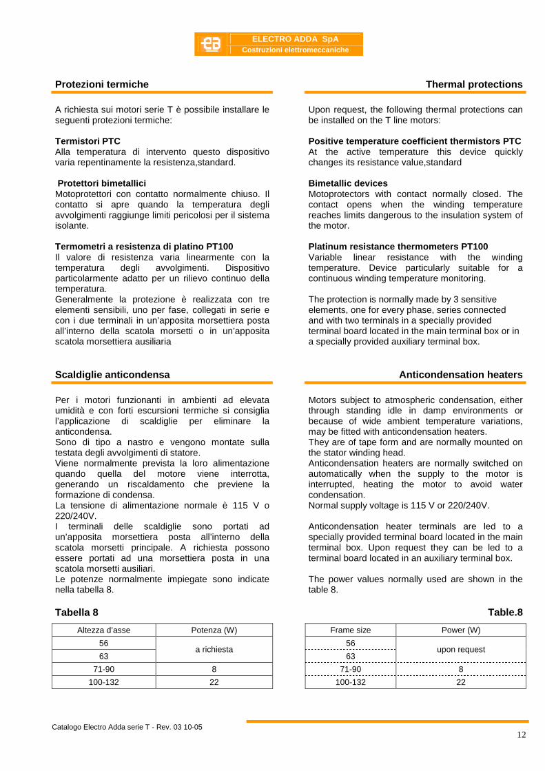
A richiesta sui motori serie T è possibile installare le seguenti protezioni termiche: Termistori PTC Alla temperatura di intervento questo dispositivo varia repentinamente la resistenza,standard. Protettori bimetallici Motoprotettori con contatto normalmente chiuso. Il contatto si apre quando la temperatura degli avvolgimenti raggiunge limiti pericolosi per il sistema isolante. Termometri a resistenza di platino PT100 Il valore di resistenza varia linearmente con la temperatura degli avvolgimenti. Dispositivo particolarmente adatto per un rilievo continuo della temperatura. Generalmente la protezione è realizzata con tre elementi sensibili, uno per fase, collegati in serie e con i due terminali in un’apposita morsettiera posta all’interno della scatola morsetti o in un’apposita scatola morsettiera ausiliaria
Upon request, the following thermal protections can be installed on the T line motors: Positive temperature coefficient thermistors PTC At the active temperature this device quickly changes its resistance value,standard Bimetallic devices Motoprotectors with contact normally closed. The contact opens when the winding temperature reaches limits dangerous to the insulation system of the motor. Platinum resistance thermometers PT100 Variable linear resistance with the winding temperature. Device particularly suitable for a continuous winding temperature monitoring. The protection is normally made by 3 sensitive elements, one for every phase, series connected and with two terminals in a specially provided terminal board located in the main terminal box or in a specially provided auxiliary terminal box.
Scaldiglie anticondensa Anticondensation heaters
Per i motori funzionanti in ambienti ad elevata umidità e con forti escursioni termiche si consiglia l’applicazione di scaldiglie per eliminare la anticondensa. Sono di tipo a nastro e vengono montate sulla testata degli avvolgimenti di statore. Viene normalmente prevista la loro alimentazione quando quella del motore viene interrotta, generando un riscaldamento che previene la formazione di condensa. La tensione di alimentazione normale è 115 V o 220/240V. I terminali delle scaldiglie sono portati ad un’apposita morsettiera posta all’interno della scatola morsetti principale. A richiesta possono essere portati ad una morsettiera posta in una scatola morsetti ausiliari. Le potenze normalmente impiegate sono indicate nella tabella 8. Tabella 8
Motors subject to atmospheric condensation, either through standing idle in damp environments or because of wide ambient temperature variations, may be fitted with anticondensation heaters. They are of tape form and are normally mounted on the stator winding head. Anticondensation heaters are normally switched on automatically when the supply to the motor is interrupted, heating the motor to avoid water condensation. Normal supply voltage is 115 V or 220/240V. Anticondensation heater terminals are led to a specially provided terminal board located in the main terminal box. Upon request they can be led to a terminal board located in an auxiliary terminal box. The power values normally used are shown in the table 8.
Table .8
Altezza d’asse Potenza (W) Frame size Power (W)
56 56
63 a richiesta
63 upon request
71-90 8 71-90 8
100-132 22 100-132 22

ELECTRO ADDA SpA
Costruzioni elettromeccaniche
Catalogo Electro Adda serie T - Rev. 03 10-05
13
Alimentazione da inverter Inverter supply I motori serie T grandezza 56÷160 sono previsti per alimentazione da inverter. Tali motori possono essere azionati fino alla frequenza nominale (50Hz) con tensione di alimentazione proporzionale alla frequenza. (Vedere diagr.1), alle frequenze maggiori possono essere alimentati a tensione costante fino a 80Hz
The T line motors frame size 56÷132 are designed to be supplied by inverter. These motors can be driven up to the rated frequency (50Hz) with supply voltage proportional to the frequency. (See diagr.1), at higher frequencies they can be supplied at constant voltage up to the achievement of the 80Hz
0
20
40
60
80
100
120
0 20 40 60 80 100 120
Frequenza di alimentazione (Hz)
Ten
sion
e di
alim
enta
zion
e in
% d
ella
no
min
ale
Diagr. 1 - Diagramma tensione di alimentazione - frequenza.
Diagr. 1 - Supply voltage - frequency diagram.
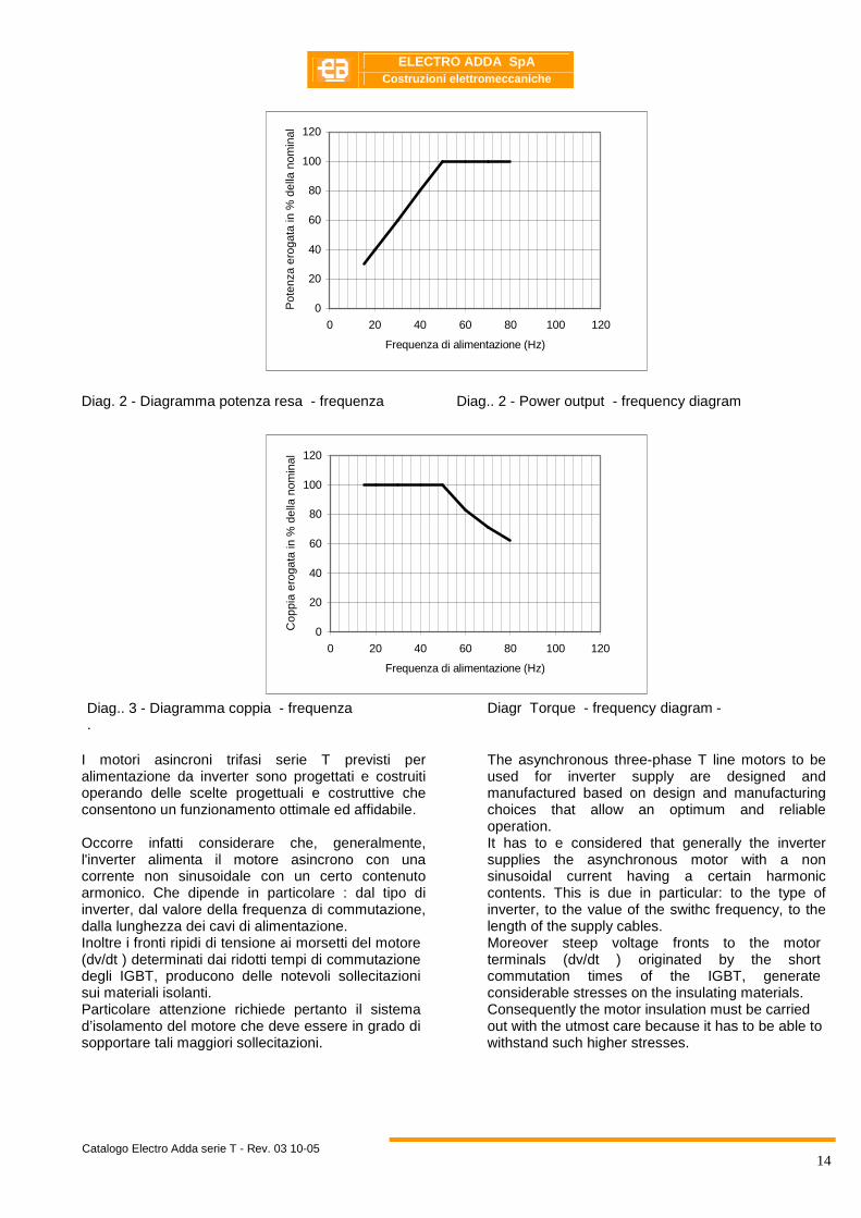
Con il tipo di alimentazione indicata nel diagr. 1, il flusso creato dagli avvolgimenti statorici risulterà costante da frequenza 15 alla frequenza di 50 Hz e conseguentemente, si potrà disporre di una coppia costante in tutto questo campo di regolazione della velocità. Alle frequenze maggiori di 50 Hz il il flusso risulterà inferiore al valore massimo e il motore potrà funzionare a potenza costante e quindi a coppia decrescente con l’aumento della frequenza (vedere diagr.2). L’andamento della potenza erogabile sarà pertanto quello riportato nel diagr. 3. Nota: Alle basse frequenze ( 0 ÷ 10 Hz. ) a causa delle cadute di tensione, per poter mantenere il flusso costante è necessario incrementare leggermente la tensione di alimentazione. Tale incremento di tensione dipende sia dal tipo di motore che dal tipo di inverter.
By the type of supply shown in diagr. 1, the flux created by the stator windings will be constant from 15 frequency to 50 Hz frequency and consequently a constant torque in all this speed control range is available. At frequencies higher than 50 Hz, the flux will be lower than the maximum value and the motor can run at constant power and therefore at a power decreasing with the increase of frequency (see diagr.2). Consequently the pattern of the deliverable power output will be as shown in diagr. 3. Note: At low frequencies ( 0 ÷ 10 Hz. ) due to the voltage drops, in order to keep the flux constant, the supply voltage should be slightly increased. This voltage increase depends both on the motor type and on the inverter type.
ELECTRO ADDA SpA
Costruzioni elettromeccaniche
Catalogo Electro Adda serie T - Rev. 03 10-05
14
0
20
40
60
80
100
120
0 20 40 60 80 100 120
Frequenza di alimentazione (Hz)
Pot
enza
ero
gata
in %
del
la n
omin
ale
Diag. 2 - Diagramma potenza resa - frequenza Diag.. 2 - Power output - frequency diagram
0
20
40
60
80
100
120
0 20 40 60 80 100 120
Frequenza di alimentazione (Hz)
Cop
pia
erog
ata
in %
del
la n
omin
ale
Diag.. 3 - Diagramma coppia - frequenza .
Diagr Torque - frequency diagram -
I motori asincroni trifasi serie T previsti per alimentazione da inverter sono progettati e costruiti operando delle scelte progettuali e costruttive che consentono un funzionamento ottimale ed affidabile. Occorre infatti considerare che, generalmente, l'inverter alimenta il motore asincrono con una corrente non sinusoidale con un certo contenuto armonico. Che dipende in particolare : dal tipo di inverter, dal valore della frequenza di commutazione, dalla lunghezza dei cavi di alimentazione. Inoltre i fronti ripidi di tensione ai morsetti del motore (dv/dt ) determinati dai ridotti tempi di commutazione degli IGBT, producono delle notevoli sollecitazioni sui materiali isolanti. Particolare attenzione richiede pertanto il sistema d’isolamento del motore che deve essere in grado di sopportare tali maggiori sollecitazioni.
The asynchronous three-phase T line motors to be used for inverter supply are designed and manufactured based on design and manufacturing choices that allow an optimum and reliable operation. It has to e considered that generally the inverter supplies the asynchronous motor with a non sinusoidal current having a certain harmonic contents. This is due in particular: to the type of inverter, to the value of the swithc frequency, to the length of the supply cables. Moreover steep voltage fronts to the motor terminals (dv/dt ) originated by the short commutation times of the IGBT, generate considerable stresses on the insulating materials. Consequently the motor insulation must be carried out with the utmost care because it has to be able to withstand such higher stresses.

ELECTRO ADDA SpA
Costruzioni elettromeccaniche
Catalogo Electro Adda serie T - Rev. 03 10-05
15
Velocità massima Maximum speed
I motori alimentati da inverter possono funzionare a frequenza maggiore di quella nominale fornendo la potenza nominale fino alla frequenza massima indicata nella tabella 9. In tali condizioni la coppia massima del motore alla velocità massima rimane superiore a 1.6 volte la coppia nominale. Tabella 9
Motors supplied by inverter may run at a frequency higher than the rated one, delivering the rated power up to the maximum frequency shown in table 9. In such conditions the motor pullout torque at the maximum speed remains higher than 1.6 times the rated torque.
Table 9
Frequenza massima di alimentazione Max alimentation frequency Altezza d’asse
Frame 2 Poli 2 Poles
4 Poli 4 Poles
6 Poli 6 Poles
8 Poli 8 Poles
56 ÷ 90 75 75 60 60
100 ÷ 112 70 70 60 60
132 ÷ 160 65 65 60 60
E’ altresì possibile alimentare i motori a frequenza superiore, in tal caso le potenze erogabili dal motori si ridurranno progressivamente. In ogni caso le velocità massime dei motori, anche in funzionamento a vuoto o trascinato dalla macchina operatrice, non deve mai superare i limiti indicati nella tabella 10. Tabella 10
It is also possible to supply motors at a higher frequency, in this case the motor outputs will be progressively reduced. In any case the maximum motor speeds, even in idle operation or pulled by the machine tool, must never exceed the limits shown in table 10.
Table 10
Velocità massima ammessa Maximun allowable speed Motore tipo
Motor type 2 Poli
2 Poles 4 Poli
4 Poles 6 Poli
6 Poles 8 Poli
8 Poles
63 7000 5000 4800 4800
71 7000 5000 4800 4800
80 7000 5000 4800 4800
90 7000 5000 4800 4800
100 7000 5000 4800 4800
112 7000 5000 4800 4800
132 6500 5000 4800 4800
160 6000 5000 4800 4800
ELECTRO ADDA SpA
Costruzioni elettromeccaniche
Catalogo Electro Adda serie T - Rev. 03 10-05
16
Funzionamento a potenza aumentata Increased power operating
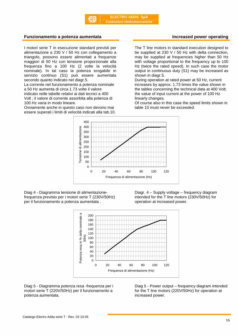
I motori serie T in esecuzione standard previsti per alimentazione a 230 V / 50 Hz con collegamento a triangolo, possono essere alimentati a frequenze maggiori di 50 Hz con tensione proporzionale alla frequenza fino a 100 Hz (2 volte la velocità nominale). In tal caso la potenza erogabile in servizio continuo (S1) può essere aumentata secondo quanto indicato nel diagr.5. La corrente nel funzionamento a potenza nominale a 50 Hz aumenta di circa 1.73 volte il valore indicato nelle tabelle relativi ai dati tecnici a 400 Volt ; il valore di corrente assorbita alla potenza di 100 Hz varia in modo lineare. Ovviamente anche in questo caso non devono mai essere superati i limiti di velocità indicati alla tab.10.
The T line motors in standard execution designed to be supplied at 230 V / 50 Hz with delta connection, may be supplied at frequencies higher than 50 Hz with voltage proportional to the frequency up to 100 Hz (twice the rated speed). In such case the motor output in continuous duty (S1) may be increased as shown in diagr.5. During operation at rated power at 50 Hz, current increases by approx. 1.73 times the value shown in the tables concerning the technical data at 400 Volt; the value of input current at the power of 100 Hz linearly changes. Of course also in this case the speed limits shown in table 10 must never be exceeded.
0
50
100
150
200
250
300
350
400
450
0 20 40 60 80 100 120
Frequenza di alimentazione (Hz)
Ten
sion
e di
alim
enta
zion
e
Diag 4 - Diagramma tensione di alimentazione-frequenza previsto per i motori serie T (230V/50Hz) per il funzionamento a potenza aumentata .
Diagr. 4 – Supply voltage – frequency diagram intended for the T line motors (230V/50Hz) for operation at increased power.
020406080
100120140160180200
0 20 40 60 80 100 120
Frequenza di alimentazione (Hz)
Pot
enza
res
a in
% d
ella
nom
inal
e a
50H
z
Diag 5 - Diagramma potenza resa -frequenza per i motori serie T (220V/50Hz) per il funzionamento a potenza aumentata.
Diag 5 - Power output – frequency diagram intended for the T line motors (220V/50Hz) for operation at increased power.
ELECTRO ADDA SpA
Costruzioni elettromeccaniche
Catalogo Electro Adda serie T - Rev. 03 10-05
17
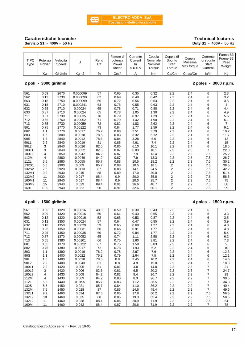
Caratteristiche tecniche Servizio S1 - 400V - 50 Hz
Technical features Duty S1 - 400V - 50 Hz
TIPO Type
Potenza Power
Velocità Speed J Rend
Eff
Fattore di potenza Power factor
Corrente Current
In a 400 V
Coppia Nominale Nominal Torque
Coppia di Spunto Start
Torque
Coppia Massima
Max torque
Corrente di spunto
Start Current
Forma B3 Frame B3
Peso Weight
Kw Giri/min Kgm2 % Cosfi A Nm Ca/Cn Cmax/Cn Ia/In Kg
2 poli - 3000 giri/min 2 poles - 3000 r.p.m .
561 0.09 2670 0.000099 57 0.65 0.35 0.32 2.2 2.4 6 2.8 562 0.12 2730 0.000099 62 0.69 0.40 0.42 2.2 2.4 6 3.2 563 0.18 2750 0.000099 65 0.72 0.56 0.63 2.2 2.4 6 3.5 631 0.18 2710 0.000241 63 0.75 0.55 0.63 2.2 2.4 6 4 632 0.25 2710 0.00024 65 0.78 0.71 0.88 2.2 2.4 6 4.4 633 0.37 2710 0.00024 65 0.78 1.05 1.30 2.2 2.4 6 4.9 711 0.37 2730 0.00035 70 0.79 0.97 1.29 2.2 2.4 6 5.6 712 0.55 2760 0.00052 71 0.79 1.42 1.90 2.2 2.4 6 6.1 713 0.75 2730 0.00059 72 0.82 1.83 2.62 2.2 2.4 6 7 801 0.75 2770 0.00122 73 0.84 1.77 2.59 2.2 2.4 6 9.1 802 1.1 2770 0.0017 76.2 0.83 2.51 3.79 2.2 2.4 6 10.2 803 1.5 2800 0.0018 78.5 0.83 3.32 5.12 2.2 2.4 6 11.7 90S 1.5 2840 0.0012 78.5 0.84 3.28 5.0 2.2 2.4 6 12 90L1 2.2 2840 0.0019 81 0.85 4.61 7.4 2.2 2.4 6 15 90L2 3 2840 0.0026 82.6 0.86 6.10 10.1 2.2 2.4 6 18.5 100L1 3 2840 0.0032 82.6 0.87 6.03 10.1 2.2 2.3 7 22.3 100L2 4 2850 0.0042 84.2 0.87 7.9 13.4 2.2 2.3 7.5 25.2 112M 4 2880 0.0049 84.2 0.87 7.9 13.3 2.2 2.3 7.5 26.7 112L 5.5 2880 0.0055 85.7 0.88 10.5 18.2 2.2 2.3 7.5 30.2 132S1 5.5 2900 0.009 85.7 0.88 10.5 18.1 2 2.2 7.5 38.5 132S2 7.5 2920 0.0113 87 0.88 14.1 24.5 2 2.2 7.5 42.2 132M1 9.2 2930 0.015 88 0.89 17.0 30.0 2 2.2 7.5 51.4 132M2 11 2930 0.017 88.4 0.9 20.0 35.8 2 2.2 7.5 58.8 160M1 11 2940 0.017 88.4 0.9 20.0 35.7 2 2.2 7.5 75 160M2 15 2940 0.023 89.4 0.91 26.6 48.7 2 2.2 7.5 88 160L 18.5 2940 0.032 90 0.91 32.6 60.1 2 2.2 7.5 99
4 poli - 1500 giri/min 4 poles - 1500 r.p.m .
561 0.06 1320 0.00016 48.5 0.59 0.30 0.43 2.3 2.4 6 3 562 0.09 1320 0.00016 50 0.61 0.43 0.65 2.3 2.4 6 3.3 563 0.12 1320 0.00016 52 0.63 0.53 0.87 2.2 2.4 6 3.5 631 0.12 1350 0.00024 57 0.64 0.47 0.85 2.2 2.4 6 3.9 632 0.18 1350 0.00029 59 0.65 0.68 1.27 2.2 2.4 6 4.3 633 0.25 1350 0.00031 60 0.66 0.91 1.77 2.2 2.4 6 4.8 711 0.25 1350 0.00035 60 0.72 0.84 1.77 2.2 2.4 6 5.4 712 0.37 1370 0.00052 65 0.74 1.11 2.58 2.2 2.4 6 6.2 713 0.55 1380 0.00101 66 0.75 1.60 3.81 2.2 2.4 6 7.3 801 0.55 1370 0.00122 67 0.75 1.58 3.83 2.2 2.4 6 9 802 0.75 1380 0.0017 72 0.78 1.93 5.2 2.2 2.4 6 10 803 1.1 1390 0.0019 76.2 0.78 2.67 7.6 2.2 2.4 6 12.3 90S 1.1 1400 0.0022 76.2 0.79 2.64 7.5 2.2 2.4 6 12.1 90L 1.5 1400 0.0028 78.5 0.8 3.45 10.2 2.2 2.4 6 14.6 90L2 2.2 1400 0.0043 81 0.8 4.9 15.0 2.2 2.4 7 18.3 100L1 2.2 1420 0.005 81 0.81 4.8 14.8 2.2 2.3 7 21 100L2 3 1420 0.006 82.6 0.81 6.5 20.2 2.2 2.3 7 24.7 100L3 4 1430 0.008 84.2 0.82 8.4 26.7 2.2 2.3 7 29 112M 4 1430 0.009 84.2 0.83 8.3 26.7 2.2 2.2 7 30.5 112L 5.5 1440 0.0195 85.7 0.83 11.2 36.5 2.2 2.2 7 34.8 132S 5.5 1450 0.021 85.7 0.84 11.0 36.2 2.2 2.2 7 40.4 132M 7.5 1450 0.028 87 0.85 14.6 49.4 2.2 2.2 7 49.6 132L1 9.2 1460 0.034 87.5 0.85 17.9 60.2 2.2 2.2 7.5 56.5 132L2 10 1460 0.035 88 0.85 19.3 65.4 2.2 2.2 7.5 58.5 132L2 11 1460 0.038 88.4 0.86 20.9 71.9 2.2 2.2 7.5 64 160M 11 1460 0.042 88.4 0.87 20.6 71.9 2.2 2.2 7 78

ELECTRO ADDA SpA
Costruzioni elettromeccaniche
Catalogo Electro Adda serie T - Rev. 03 10-05
18
TIPO Type
Potenza Power
Velocità Speed
J Rend Eff
Fattore di potenza Power factor
Corrente Current
In a 400 V
Coppia Nominale Nominal Torque
Coppia di Spunto Start
Torque
Coppia Massima
Max torque
Corrente di spunto
Start Current
Forma B3 Frame B3
Peso Weight
Kw Giri/min Kgm2 % Cosfi A Nm Ca/Cn Cmax/Cn Ia/In Kg
6 poli - 1000 giri/min 6 poles - 1000 r.p.m .
631 0.09 840 0.00040 42 0.61 0.51 1.02 2 2 3.5 4.2 632 0.12 850 0.00050 45 0.62 0.62 1.35 2 2 3.5 4.8 711 0.18 880 0.00105 56 0.66 0.70 1.95 1.6 1.7 4 6 712 0.25 900 0.00129 59 0.7 0.87 2.65 2.1 2.2 4 6.5 713 0.37 890 0.00145 61 0.69 1.27 3.97 2 2.1 4 7.2 801 0.37 900 0.00164 62 0.7 1.23 3.93 1.9 1.9 4 8.2 802 0.55 900 0.00256 67 0.72 1.65 5.8 2 2.3 4 9.9 803 0.75 900 0.0031 68 0.72 2.21 8.0 2 2.3 4 11.3 90S 0.75 920 0.00354 69 0.72 2.18 7.8 2.2 2.2 5.5 11.7 90L 1.1 925 0.0051 72 0.73 3.02 11.4 2.2 2.2 5.5 15.1 100L 1.5 945 0.0079 74 0.76 3.85 15.2 2.2 2.2 6 19.1 112M 2.2 955 0.014 78 0.76 5.36 22.0 2.2 2.2 6 25.4 132S 3 960 0.023 79 0.76 7.2 29.8 2 2 6.5 36.1 132M1 4 960 0.031 80.5 0.76 9.4 39.8 2 2 6.5 45 132M2 5.5 960 0.041 83 0.77 12.4 54.7 2 2 6.5 55.5 132L 7.5 960 0.053 85 0.77 16.5 74.6 2 2 6.5 60 160M 7.5 960 0.075 86 0.8 15.7 74.6 2 2.2 6.5 72 160L 11 960 0.109 87.5 0.79 23.0 109.4 2 2.2 6.5 92
8 poli - 750 giri/min 8 poles - 750 r.p.m .
711 0.09 680 0.00105 48 0.56 0.48 1.26 1.5 1.7 3 6 712 0.12 690 0.00119 51 0.59 0.58 1.66 1.6 1.7 2.7 6.8 801 0.18 680 0.00164 51 0.61 0.84 2.53 1.5 1.7 2.8 9.9 802 0.25 680 0.0029 56 0.61 1.06 3.51 1.6 2 2.7 10.9 90S 0.37 680 0.0049 63 0.63 1.35 5.20 1.6 1.8 2.8 14.8 90L 0.55 680 0.0057 66 0.65 1.85 7.7 1.6 1.8 3 17.2 100L1 0.75 710 0.075 66 0.67 2.45 10.1 1.7 2.1 3.5 17.5 100L2 1.1 710 0.084 72 0.69 3.20 14.8 1.7 2.1 3.5 19.7 112M 1.5 710 0.015 74 0.68 4.30 20.2 1.8 2.1 4.2 25.6 132S 2.2 720 0.022 75 0.71 6.0 29.2 2 2 5.5 35.5 132M 3 720 0.031 77 0.73 7.7 39.8 2 2 5.5 45 160M1 4 730 0.053 80 0.73 9.9 52.3 1.9 2.1 6 60 160M2 5.5 720 0.075 83.5 0.74 12.8 72.9 2 2.2 6 72 160L 7.5 720 0.109 85 0.75 17.0 99.5 1.9 2.2 6 92

ELECTRO ADDA SpA
Costruzioni elettromeccaniche
Catalogo Electro Adda serie T - Rev. 03 10-05
19
TIPO Type
Potenza Power
Velocità Speed
J Rend Eff
Fattore di
potenza Power factor
Corrente Current
In a 400 V
Coppia Nominale Nominal Torque
Cn
Coppia di Spunto
Start Torque
Corrente di spunto
Start Current
Ia/In
Coppia Massima
Max torque
Forma Frame
B3 Peso
Weight Kw Giri/min Kgm2 % Cosfi A Nm Ca/Cn Cmax/Cn Kg
2/4 poli - 3000/1500 giri/min 2/4 poles - 3000/1500 r.p.m.
56 0.11/0.07 2660/1330 0.00016 50/42 0.82/0.66 0.39/0.36 0.4/0.5 1.6/1.4 4/3 1.7/1.5 3.4 63 0.15/0.11 2680/1340 0.00024 54/53 0.82/0.67 0.49/0.45 0.53/0.58 1.7/1.5 4/3 1.8/1.6 4 63 0.22/0.15 2690/1340 0.00029 61/59 0.86/0.67 0.61/0.55 1.7/1.4 1.7/1.5 4/3 1.8/1.6 4.6 71 0.3/0.22 2760/1330 0.00035 60/55 0.8/0.73 0.9/0.79 1.04/1.56 1.7/1.5 3.5/3.5 1.9/1.6 6.4 71 0.45/0.3 2790/1370 0.00052 63/58 0.8/0.73 1.29/1.02 1.54/2.08 2/1.8 4/4 2/1.7 7.5 80 0.55/0.45 2820/1380 0.00120 65/64 0.84/0.75 1.45/1.35 1.88/3.11 2/1.8 4.5/4.5 2.1/1.8 8.9 80 0.75/0.6 2830/1410 0.00170 67/68 0.86/0.77 1.9/1.65 2.56/4.1 1.8/1.7 4./4.55 2/1.8 10.9 90S 1.25/0.95 2830/1380 0.00220 72/68 0.86/0.82 2.9/2.5 4.2/6.5 2/1.8 5/5 2/1.8 12.5 90L 1.7/1.32 2840/1400 0.00280 73/70 0.86/0.83 3.9/3.3 5.74/9 2/1.8 5/5 2/1.8 15.7 100L 2.4/1.84 2840/1400 0.00570 73/76 0.86/0.83 5.5/4.2 8.1/12.5 2/1.8 5.5/5 2/1.6 22 100L 3.2/2.6 2850/1420 0.00780 74/78 0.86/0.85 7.5/5.7 11.1/17.8 2/1.9 5.5/5 2/1.9 23.5 112M 4.5/4 2870/1420 0.00920 77/79 0.85/0.86 9.9/8.5 15/26.7 2/1.8 5.5/5 2.2/2 28.9 132S 6/5 2870/1440 0.02100 79/82 0.84/0.86 13.05/10.2 20/33.2 2/1.5 5./55 2.2/1.9 45 132M 8/6.6 2875/1440 0.02800 82/84 0.84/0.86 16.8/13.1 26.6/43.8 2/1.9 6/6 2.2/1.9 54
4/6 poli - 1500/1000 giri/min 4/6 poles - 1500/1000 r.p.m.
71 0.22/0.15 1400/900 0.00129 52/45 0.70/0.68 0.87/0.71 1.5/1.59 1.8/1.9 3/2.7 1.9/1.8 6.9 80 0.3/0.22 1400/910 0.00164 60/65 0.74/0.69 0.98/0.84 2.05/2.31 1.8/1.7 4.5/4 2/1.8 7.8 80 0.45/0.3 1410/920 0.00256 63/58 0.75/0.7 1.37/1.07 3.05/3.11 1.8/1.7 4.5/4 2/1.8 11 90S 0.66/0.45 1410/920 0.00354 66/61 0.76/0.65 1.9/1.64 4.47/4.67 1.7/1.6 5/4.5 2/1.7 14.7 90L 0.88/0.6 1420/930 0.00505 70/64 0.77/0.67 2.36/2.02 5.92/6.16 1.7/1.6 5/4.5 2/1.9 15.9 100L 1.32/0.88 1420/940 0.00870 72/67 0.85/0.75 3.11/2.3 8.88/8.94 1.8/1.7 6/5 2/1.8 21 100L 1.76/1.2 1430/950 0.01200 74/70 0.85/0.75 4.04/3.3 11.75/12.06 1.8/1.7 6/5 2/1.8 24 112M 2.2/1.5 1430/950 0.01400 76/70 0.8/0.7 5.22/4.42 14.69/15 2/1.8 6/5 2.2/2 27.3 132S 3.3/2.2 1440/960 0.03100 82/78 0.81/0.72 7.17/5.65 21.9/22.0 2/1.8 7/6 2.2/2.1 48 132M 4.5/3 1450/970 0.04100 83/80 0.82/0.74 9.45/7.31 29.6/29.5 2/1.8 7/6 2.3/2.1 56
6/8 poli - 1000/750 giri/min 6/8 poles - 1000/750 r.p.m.
71 0.11/0.075 900/680 0.00129 41/33 0.67/0.60 0.58/0.55 1.19/1.07 1.3/1.3 2/1.9 1.5/1.5 7 80 0.18/0.11 900/680 0.00164 50/42 0.69/0.65 0.75/0.58 1.91/1.54 1.5/1.3 3.5/3 1.5/1.5 8.6 80 0.25/0.18 920/700 0.00256 54/46 0.7/0.66 0.95/0.86 2.6/2.46 1.7/1.5 3.5/3 1.5/1.7 10.7 90S 0.37/0.25 930/680 0.00354 58/50 0.72/0.68 1.28/1.06 3.8/3.51 1.5/1.4 4/3 1.8/1.8 11.8 90L 0.55/0.37 940/685 0.00505 63/54 0.73/0.69 1.73/1.43 5.59/5.16 1.5/1.4 4/3 1.8/1.7 14.9 100L 0.75/0.55 950/700 0.00870 69/63 0.74/0.74 2.12/1.7 7.54/7.5 1.5/1.4 5/4 4/2 21 100L 1.03/0.75 955/705 0.01200 71/65 0.76/0.76 2.76/2.19 10.3/10.16 1.5/1.4 5/4 4/2 27 112M 1.25/0.95 960/710 0.01400 72/64 0.71/0.71 3.53/3.02 12.43/12.78 1.6/1.4 5/4 2/1.8 28.9 132S 2.2/1.5 970/720 0.03100 76/70 0.71/0.7 5.88/4.42 21.66/19.9 1.6/1.4 6/5.5 2.3/2 48.9 132M 3/1.85 970/720 0.04100 78/74 0.71/0.7 7.82/5.01 29.54/24.37 1.6/1.4 6/5.5 2.3/2 58.6

ELECTRO ADDA SpA
Costruzioni elettromeccaniche
Catalogo Electro Adda serie T - Rev. 03 10-05
20
TIPO Type
Potenza Power
Velocità Speed J Rend
Eff
Fattore di
potenza Power factor
Corrente Current
In a 400 V
Coppia Nominale Nominal Torque
Cn
Coppia di Spunto
Start Torque
Corrente di spunto
Start Current
Ia/In
Coppia Massima
Max torque
Forma Frame
B3 Peso
Weight Kw Giri/min Kgm2 % Cosfi A Nm Ca/Cn Cmax/Cn Kg
4/8 poli - 1500/750 giri/min 4/8 poles - 1500/750 r.p.m.
71 0.18/0.11 1380/680 0.00129 53/42 0.68/0.53 0.76/0.75 1.29/1.59 2/1.8 3.6/2.2 1.9/1.7 6.5 80 0.25/0.15 1380/680 0.00164 58/40 0.77/0.6 0.81/0.9 1.73/2.11 2/2.1 4.5/3 2/1.8 8.4 80 0.45/0.25 1390/685 0.00256 68/48 0.8/0.6 1.19/1.25 3.09/3.49 1.8/2 4.5/3 2/1.8 11 90S 0.55/0.3 1400/690 0.00303 68/50 0.83/0.61 1.41/1.42 3.75/4.15 1.8/2 4.5/3.5 2/1.8 12.9 90L 0.8/0.45 1400/690 0.00450 68/53 0.83/0.63 2.05/1.95 5.46/6.23 1.8/1.6 4/3 1.9/1.8 14.9 100L 1.25/0.6 1400/700 0.00870 69/54 0.82/0.56 3.19/2.86 8.53/8.16 1.8/2 5/3.5 2/1.7 21.8 100L 1.76/0.88 1400/700 0.01090 71/58 0.84/0.56 4.26/3.91 12/12 1.8/2 5.5/4 2/1.8 24 112M 2.2/1.5 1420/700 0.01410 75/64 0.82/0.61 5.16/5.54 14.8/20.46 2/1.6 6/4 2/1.8 28.7 132S 3.3/2.2 1430/705 0.03070 78/70 0.84/0.64 7.27/7.09 22.04/29.8 2/1.5 6/5 2/1.9 48.3 132M 4.5/3 1430/705 0.0410 82/77 0.85/0.65 9.32/8.65 30.05/40.64 2/1.6 6/5 2/1.8 56.5
2/8 poli - 3000/750 giri/min 2/8 poles - 3000/750 r.p.m.
71 0.25/0.66 2690/650 0.00052 62/20 0.78/0.58 0.90/0.85 0.89/0.88 1.7/2 3/2 1.9/2 6.4 80 0.37/0.08 2760/660 0.00160 65/33 0.76/0.48 1.08/0.73 1.28/1.16 1.7/2 3.5/2.5 1.9/2.1 8.9 80 0.55/0.11 2780/670 0.00260 67/35 0.78/0.5 1.52/0.91 1.89/1.57 1.7/2 4/3 1.9/2.2 11 90S 0.75/0.18 2800/670 0.00350 67/43 0.79/0.52 2.05/1.16 2.56/2.57 1.8/2 4/3 2/2.3 13.2 90L 1.1/0.3 2810/680 0.00510 67/45 0.8/0.54 2.96/1.78 3.74/4.21 1.8/2 4/3.5 2/2.3 15.1 100L 1.5/0.37 2820/700 0.00870 67/50 0.84/0.56 3.85/1.91 5.08/5.05 1.7/2.1 5/3.5 2/2.6 22 100L 2.2/0.55 2820/710 0.01300 69/51 0.85/0.58 5.49/2.68 7.45/7.4 1.8/2.2 5/3.5 2/2.6 25.4 112M 2.6/0.75 2840/710 0.01400 71/58 0.86/0.6 6.15/3.11 8.74/10.09 1.8/2 5.5/4 1.9/2.1 28 112M 3/0.9 2850/710 0.01500 75/63 0.86/0.58 6.71/3.56 10.05/12.1 1.7/2 6.5/4.5 1.9/2.2 40 132S 3.7/1.1 2890/710 0.02400 81/65 0.83/0.57 7.94/4.29 12.22/14.8 1.7/1.6 7/5 1.9/1.9 49.8
ELECTRO ADDA SpA
Costruzioni elettromeccaniche
Catalogo Electro Adda serie T - Rev. 03 10-05
21
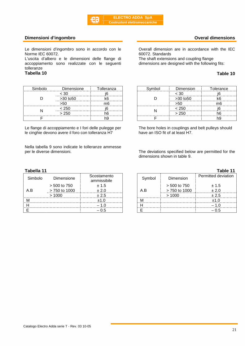
Dimensioni d’ingombro Overal dimensions
Le dimensioni d’ingombro sono in accordo con le Norme IEC 60072. L’uscita d’albero e le dimensioni delle flange di accoppiamento sono realizzate con le seguenti tolleranze Tabella 10
Overall dimension are in accordance with the IEC 60072. Standards The shaft extensions and coupling flange dimensions are designed with the following fits:
Table 10
Simbolo Dimensione Tolleranza Symbol Dimension Tolerance < 30 j6 < 30 j6 >30 to50 k6 >30 to50 k6 D >50 m6
D >50 m6
< 250 j6 < 250 j6 N
> 250 h6 N
> 250 h6 F h9 F h9
Le flange di accoppiamento e I fori delle pulegge per le cinghie devono avere il foro con tolleranza H7 Nella tabella 9 sono indicate le tolleranze ammesse per le diverse dimensioni. Tabella 11
The bore holes in couplings and belt pulleys should have an ISO fit of at least H7. The deviations specified below are permitted for the dimensions shown in table 9.
Table 11
Simbolo Dimensione Scostamento ammissibile
Symbol Dimension
Permitted deviation
> 500 to 750 ± 1.5 > 500 to 750 ± 1.5 > 750 to 1000 ± 2.0 > 750 to 1000 ± 2.0 A.B > 1000 ± 2.5
A.B > 1000 ± 2.5
M ±1.0 M ±1.0 H – 1.0 H – 1.0 E – 0.5 E – 0.5
ELECTRO ADDA SpA
Costruzioni elettromeccaniche
Catalogo Electro Adda serie T - Rev. 03 10-05
22
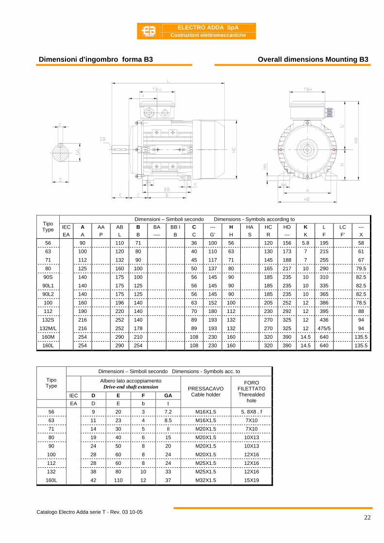
Dimensioni d’ingombro forma B3 Overall dimensions Mounting B3
Dimensioni – Simboli secondo Dimensions - Symbols according to
IEC A AA AB B BA BB I C --- H HA HC HD K L LC --- Tipo Type
EA A P L B ---- B C G’ H S R --- K F F’ X
56 90 110 71 36 100 56 120 156 5.8 195 58
63 100 120 80 40 110 63 130 173 7 215 61
71 112 132 90 45 117 71 145 188 7 255 67
80 125 160 100 50 137 80 165 217 10 290 79.5
90S 140 175 100 56 145 90 185 235 10 310 82.5
90L1 140 175 125 56 145 90 185 235 10 335 82.5
90L2 140 175 125 56 145 90 185 235 10 365 82.5
100 160 196 140 63 152 100 205 252 12 386 78.5
112 190 220 140 70 180 112 230 292 12 395 88
132S 216 252 140 89 193 132 270 325 12 436 94
132M/L 216 252 178 89 193 132 270 325 12 475/5 94
160M 254 290 210 108 230 160 320 390 14.5 640 135.5
160L
254 290 254 108 230 160 320 390 14.5 640 135.5
Dimensioni – Simboli secondo Dimensions - Symbols acc. to
Albero lato accoppiamento Drive-end shaft extension
Tipo Type
IEC D E F GA
EA D E b t
PRESSACAVO Cable holder
FORO FILETTATO Therealded
hole
56 9 20 3 7.2 M16X1.5 5. 8X8 . f
63 11 23 4 8.5 M16X1.5 7X10
71 14 30 5 Il M20X1.5 7X10
80 19 40 6 15 M20X1.5 10X13
90 24 50 8 20 M20X1.5 10X13
100 28 60 8 24 M20X1.5 12X16
112 28 60 8 24 M25X1.5 12X16
132 38 80 10 33 M25X1.5 12X16
160L
42 110 12 37 M32X1.5 15X19
ELECTRO ADDA SpA
Costruzioni elettromeccaniche
Catalogo Electro Adda serie T - Rev. 03 10-05
23
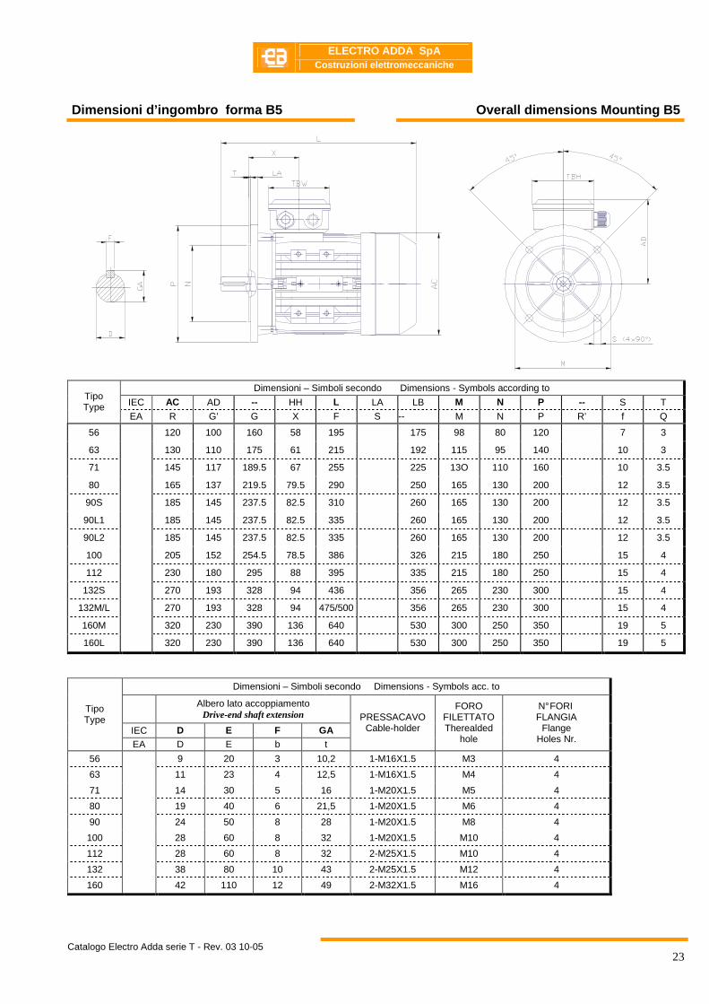
Dimensioni d’ingombro forma B5 Overall dimensions Mounting B5
Dimensioni – Simboli secondo Dimensions - Symbols according to
IEC AC AD -- HH L LA LB M N P -- S T Tipo Type
EA R G’ G X F S -- M N P R’ f Q
56 120 100 160 58 195 175 98 80 120 7 3
63 130 110 175 61 215 192 115 95 140 10 3
71 145 117 189.5 67 255 225 13O 110 160 10 3.5
80 165 137 219.5 79.5 290 250 165 130 200 12 3.5
90S 185 145 237.5 82.5 310 260 165 130 200 12 3.5
90L1 185 145 237.5 82.5 335 260 165 130 200 12 3.5
90L2 185 145 237.5 82.5 335 260 165 130 200 12 3.5
100 205 152 254.5 78.5 386 326 215 180 250 15 4
112 230 180 295 88 395 335 215 180 250 15 4
132S 270 193 328 94 436 356 265 230 300 15 4
132M/L 270 193 328 94 475/500 356 265 230 300 15 4
160M 320 230 390 136 640 530 300 250 350 19 5
160L 320 230 390 136 640 530 300 250 350 19 5
Dimensioni – Simboli secondo Dimensions - Symbols acc. to
Albero lato accoppiamento Drive-end shaft extension
IEC D E F GA
Tipo Type
EA D E b t
PRESSACAVO Cable-holder
FORO FILETTATO Therealded
hole
N° FORI FLANGIA
Flange Holes Nr.
56 9 20 3 10,2 1-M16X1.5 M3 4
63 11 23 4 12,5 1-M16X1.5 M4 4
71 14 30 5 16 1-M20X1.5 M5 4
80 19 40 6 21,5 1-M20X1.5 M6 4
90 24 50 8 28 1-M20X1.5 M8 4
100 28 60 8 32 1-M20X1.5 M10 4
112 28 60 8 32 2-M25X1.5 M10 4
132 38 80 10 43 2-M25X1.5 M12 4
160
42 110 12 49 2-M32X1.5 M16 4

ELECTRO ADDA SpA
Costruzioni elettromeccaniche
Catalogo Electro Adda serie T - Rev. 03 10-05
24
Dimensioni d’ingombro forma B3/B5 Overall dimensions Mounting B3/B5
Dimensioni – Simboli secondo Dimensions - Symbols according to
IEC A H AB AC C B HD L M N S T P HH Tipo Type
EA A L C B --- F M N f Q P X
56 90 56 110 120 36 71 156 195 98 80 7 3 120 58
63 100 63 120 130 40 80 173 215 115 95 10 3 14O 61
71 112 71 132 145 45 90 188 255 130 110 10 3.5 160 67
80 125 80 160 165 50 100 217 290 165 130 12 3.5 200 79.5
90S 140 90 175 185 56 100 235 310 165 130 12 3.5 200 82.5
90L 1 140 90 175 185 56 125 235 335 165 130 12 3.5 200 82.5
90L2 140 90 175 185 56 125 235 365 165 130 12 3.5 200 82.5
100 160 100 196 205 63 140 252 386 215 180 15 4 25O 78.5
112 190 112 220 230 70 140 292 395 215 180 15 4 25O 88
132S 216 132 252 270 89 140 325 436 265 230 15 4 300 94
132M/L 216 132 252 270 89 178 325 475/500 265 230 15 4 300 94
160M 254 160 290 320 108 210 390 640 300 25O 19 5 350 136
160L 254 160 290 320 108 254 390 640 300 25O 19 5 350 136
Dimensioni – Simboli secondo Dimensions - Symbols acc. to
Albero lato accoppiamento Drive-end shaft extension
IEC D E F GA
Tipo Type
EA D E b t
PRESSACAVO Cable-holder
FORO FILETTATO Therealded
hole
N° FORI FLANGIA
Flange Holes Nr.
56 9 20 3 10,2 1-M16X1.5 7 4 63 11 23 4 12,5 1-M16X1.5 10 4
71 14 30 5 16 1-M20X1.5 10 4
80 19 40 6 21,5 1-M20X1.5 12 4
90S 24 50 8 28 1-M20X1.5 12 4
100 28 60 8 32 1-M20X1.5 15 4
112 28 60 8 32 2-M25X1.5 15 4
132S 38 80 10 43 2-M25X1.5 15 4
160M/L
42 110 12 49 2-M32X1.5 19 4
ELECTRO ADDA SpA
Costruzioni elettromeccaniche
Catalogo Electro Adda serie T - Rev. 03 10-05
25
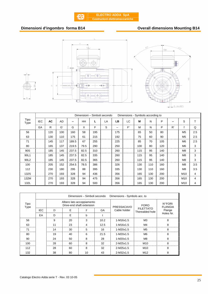
Dimensioni d’ingombro forma B14 Overall dimensions Mounting B14
Dimensioni – Simboli secondo Dimensions - Symbols according to
IEC AC AD -- HH L LA LB LC M N P -- S T Tipo Type
EA R G’ G X F S -- F’ M N P R’ f Q
56 120 100 160 58 195 175 65 50 80 M5 2.5
63 130 110 175 61 215 192 75 60 90 M5 2.5
71 145 117 189.5 67 255 225 85 70 105 M6 2.5
80 165 137 219.5 79.5 290 250 100 80 120 M6 3
90S 185 145 237.5 82.5 310 260 115 95 140 M8 3
90L1 185 145 237.5 82.5 335 260 115 95 140 M8 3
90L2 185 145 237.5 82.5 365 260 115 95 140 M8 3
100 205 152 254.5 78.5 386 326 130 110 160 M8 3.5
112 230 180 295 88 395 335 130 110 160 M8 3.5
132S 270 193 328 94 436 356 165 130 200 M10 4
132M 270 193 328 94 475 356 165 130 200 M10 4
132L 270 193 328 94 500 356 165 130 200 M10 4
Dimensioni – Simboli secondo Dimensions - Symbols acc. to
Albero lato accoppiamento Drive-end shaft extension
IEC D E F GA
Tipo Type
EA D E b t
PRESSACAVO Cable holder
FORO FILETTATO
Therealded hole
N° FORI FLANGIA
Flange Holes Nr.
56 9 20 3 10.2 1-M16x1.5 M3 8
63 11 23 4 12.5 1-M16x1.5 M4 8
71 14 30 5 16 1-M20x1.5 M5 8
80 19 40 6 21.5 1-M20x1.5 M6 8
90 24 50 8 28 1-M20x1.5 M8 8
100 28 60 8 32 2-M25x1.5 M10 8
112 28 60 8 32 2-M25x1.5 M10 8
132
38 80 10 43 2-M32x1.5 M12 8
ELECTRO ADDA SpA
Costruzioni elettromeccaniche
Catalogo Electro Adda serie T - Rev. 03 10-05
26
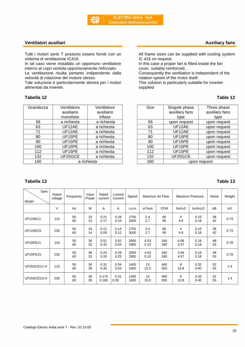
Ventilatori ausiliari Auxiliary fans
Tutti i motori serie T possono essere forniti con un sistema di ventilazione IC416. In tal caso viene installato un opportuno ventilatore interno al copri ventola opportunamente rinforzato. La ventilazione risulta pertanto indipendente dalla velocità di rotazione del motore stesso. Tale soluzione è particolarmente idonea per i motori alimentati da inverter. Tabella 12
All frame sizes can be supplied with cooling system IC 416 on request. In this case a proper fan is fitted inside the fan cover. suitably reinforced.. Consequently the ventilation is independent of the rotation speed of the motor itself. This solution is particularly suitable for inverter supplied
Table 12
Grandezza Ventilatore ausiliario monofase
Ventilatore ausiliario
trifase
Size Singole phase auxiliary fans
type
Three phase auxiliary fans
type 56 a richiesta a richiesta 56 upon request upon request 63 UF12AE a richiesta 63 UF12AE upon request 71 UF12AE a richiesta 71 UF12AE upon request 80 UF15PE a richiesta 80 UF15PE upon request 90 UF15PE a richiesta 90 UF15PE upon request 100 UF15PE a richiesta 100 UF15PE upon request 112 UF15PE a richiesta 112 UF15PE upon request 132 UF25GCE a richiesta 132 UF25GCE upon request 160 a richiesta 160 upon request
Tabella 13
Table 13
Spec
Model
Rated voltage
Frequenzy Input Power
Rated current
Locked Current
Speed Maximun Air Flow Maximun Pressure Noise Weight
V Hz W A A r.p.m m3/min CFM NnH20 InchH2O dB kG
UF12AE11 115 50 60
15 13
0.21 0.17
0.28 0.24
2700 3000
2.4 2.7
85 95
4 4.8
0.15 0.18
38 42 0.73
UF12AE23 230 50 60
16 14
0.11 0.09
0.14 0.12
2700 3000
2.4 2.7
85 95
4 4.8
0.15 0.18
38 42
0.73
UF15PE11 115 50 60
36 33
0.51 0.42
0.62 0.54
2650 2950
4.53 5.10
160 180
4.06 4.57
0.16 0.18
48 53 0.78
UF15PE23 230 50 60
36 33
0.24 0.20
0.29 0.25
2650 2950
4.53 5.10
160 180
4.06 4.57
0.16 0.18
48 53
0.78
UF25GCE11-H 115 50 60
36 39
0.31 0.30
0.54 0.53
1400 1600
13 15.5
460 550
8 10.8
0.32 0.40
52 55
1.4
UF25GCE23-H 230 50 60
36 39
0.170 0.160
0.31 0.30
1400 1600
13 15.5
460 550
8 10.8
0.32 0.40
52 55 1.4
ELECTRO ADDA SpA
Costruzioni elettromeccaniche
Catalogo Electro Adda serie T - Rev. 03 10-05
27
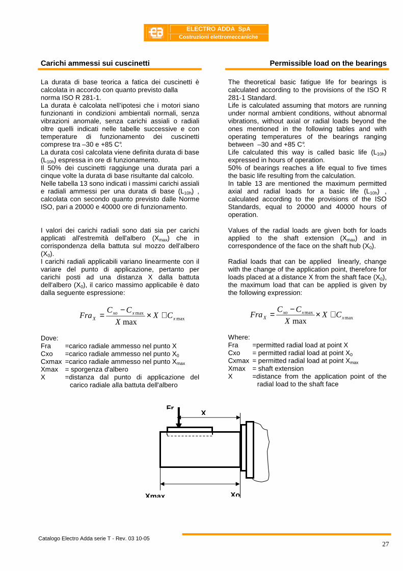
Carichi ammessi sui cuscinetti Permissible load on the bearings
La durata di base teorica a fatica dei cuscinetti è calcolata in accordo con quanto previsto dalla norma ISO R 281-1. La durata è calcolata nell’ipotesi che i motori siano funzionanti in condizioni ambientali normali, senza vibrazioni anomale, senza carichi assiali o radiali oltre quelli indicati nelle tabelle successive e con temperature di funzionamento dei cuscinetti comprese tra –30 e +85 C°. La durata così calcolata viene definita durata di base (L10h) espressa in ore di funzionamento. Il 50% dei cuscinetti raggiunge una durata pari a cinque volte la durata di base risultante dal calcolo. Nelle tabella 13 sono indicati i massimi carichi assiali e radiali ammessi per una durata di base (L10h) , calcolata con secondo quanto previsto dalle Norme ISO, pari a 20000 e 40000 ore di funzionamento. I valori dei carichi radiali sono dati sia per carichi applicati all'estremità dell'albero (Xmax) che in corrispondenza della battuta sul mozzo dell'albero (X0). I carichi radiali applicabili variano linearmente con il variare del punto di applicazione, pertanto per carichi posti ad una distanza X dalla battuta dell'albero (X0), il carico massimo applicabile è dato dalla seguente espressione:
maxmax
max xxxo
X CXX
CCFra +×
−=
Dove: Fra =carico radiale ammesso nel punto X Cxo =carico radiale ammesso nel punto X0 Cxmax =carico radiale ammesso nel punto Xmax Xmax = sporgenza d'albero X =distanza dal punto di applicazione del
carico radiale alla battuta dell'albero
The theoretical basic fatigue life for bearings is calculated according to the provisions of the ISO R 281-1 Standard. Life is calculated assuming that motors are running under normal ambient conditions, without abnormal vibrations, without axial or radial loads beyond the ones mentioned in the following tables and with operating temperatures of the bearings ranging between –30 and +85 C°. Life calculated this way is called basic life (L10h) expressed in hours of operation. 50% of bearings reaches a life equal to five times the basic life resulting from the calculation. In table 13 are mentioned the maximum permitted axial and radial loads for a basic life (L10h) , calculated according to the provisions of the ISO Standards, equal to 20000 and 40000 hours of operation. Values of the radial loads are given both for loads applied to the shaft extension (Xmax) and in correspondence of the face on the shaft hub (X0). Radial loads that can be applied linearly, change with the change of the application point, therefore for loads placed at a distance X from the shaft face (X0), the maximum load that can be applied is given by the following expression:
Where: Fra =permitted radial load at point X Cxo = permitted radial load at point X0 Cxmax = permitted radial load at point Xmax Xmax = shaft extension X =distance from the application point of the
radial load to the shaft face
Xmax Xo
X Fr
maxmax
max xxxo
X CXX
CCFra +×−=
ELECTRO ADDA SpA
Costruzioni elettromeccaniche
Catalogo Electro Adda serie T - Rev. 03 10-05
28
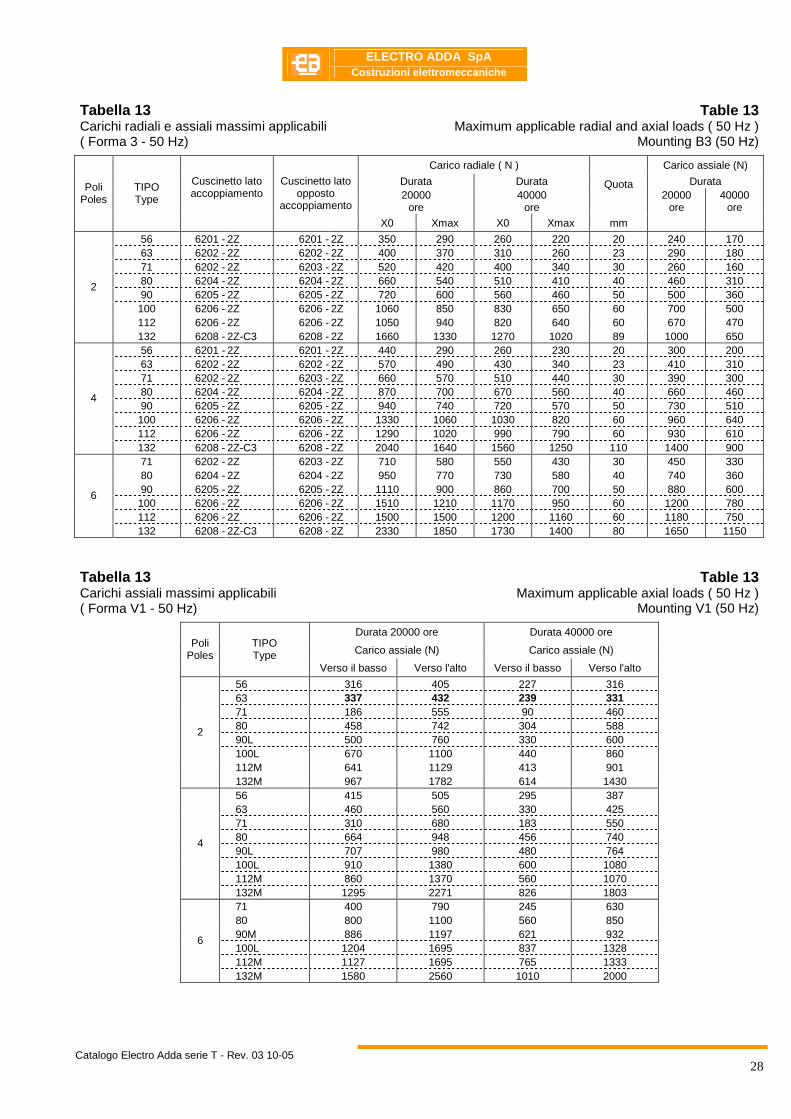
Tabella 13 Carichi radiali e assiali massimi applicabili ( Forma 3 - 50 Hz)
Table 13 Maximum applicable radial and axial loads ( 50 Hz )
Mounting B3 (50 Hz)
Carico radiale ( N ) Carico assiale (N)
Durata Durata Durata 20000
ore 40000
ore
Quota 20000
ore 40000
ore
Poli Poles
TIPO Type
Cuscinetto lato accoppiamento
Cuscinetto lato opposto
accoppiamento
X0 Xmax X0 Xmax mm 56 6201 - 2Z 6201 - 2Z 350 290 260 220 20 240 170 63 6202 - 2Z 6202 - 2Z 400 370 310 260 23 290 180 71 6202 - 2Z 6203 - 2Z 520 420 400 340 30 260 160 80 6204 - 2Z 6204 - 2Z 660 540 510 410 40 460 310 90 6205 - 2Z 6205 - 2Z 720 600 560 460 50 500 360 100 6206 - 2Z 6206 - 2Z 1060 850 830 650 60 700 500 112 6206 - 2Z 6206 - 2Z 1050 940 820 640 60 670 470
2
132 6208 - 2Z-C3 6208 - 2Z 1660 1330 1270 1020 89 1000 650 56 6201 - 2Z 6201 - 2Z 440 290 260 230 20 300 200 63 6202 - 2Z 6202 - 2Z 570 490 430 340 23 410 310 71 6202 - 2Z 6203 - 2Z 660 570 510 440 30 390 300 80 6204 - 2Z 6204 - 2Z 870 700 670 560 40 660 460 90 6205 - 2Z 6205 - 2Z 940 740 720 570 50 730 510 100 6206 - 2Z 6206 - 2Z 1330 1060 1030 820 60 960 640 112 6206 - 2Z 6206 - 2Z 1290 1020 990 790 60 930 610
4
132 6208 - 2Z-C3 6208 - 2Z 2040 1640 1560 1250 110 1400 900 71 6202 - 2Z 6203 - 2Z 710 580 550 430 30 450 330 80 6204 - 2Z 6204 - 2Z 950 770 730 580 40 740 360 90 6205 - 2Z 6205 - 2Z 1110 900 860 700 50 880 600 100 6206 - 2Z 6206 - 2Z 1510 1210 1170 950 60 1200 780 112 6206 - 2Z 6206 - 2Z 1500 1500 1200 1160 60 1180 750
6
132 6208 - 2Z-C3 6208 - 2Z 2330 1850 1730 1400 80 1650 1150 Tabella 13 Carichi assiali massimi applicabili ( Forma V1 - 50 Hz)
Table 13 Maximum applicable axial loads ( 50 Hz )
Mounting V1 (50 Hz)
Durata 20000 ore Durata 40000 ore
Carico assiale (N) Carico assiale (N) Poli
Poles TIPO Type
Verso il basso Verso l'alto Verso il basso Verso l'alto
56 316 405 227 316 63 337 432 239 331 71 186 555 90 460 80 458 742 304 588 90L 500 760 330 600 100L 670 1100 440 860 112M 641 1129 413 901
2
132M 967 1782 614 1430 56 415 505 295 387 63 460 560 330 425 71 310 680 183 550 80 664 948 456 740 90L 707 980 480 764 100L 910 1380 600 1080 112M 860 1370 560 1070
4
132M 1295 2271 826 1803 71 400 790 245 630 80 800 1100 560 850 90M 886 1197 621 932 100L 1204 1695 837 1328 112M 1127 1695 765 1333
6
132M 1580 2560 1010 2000
ELECTRO ADDA SpA
Costruzioni elettromeccaniche
Catalogo Electro Adda serie T - Rev. 03 10-05
29
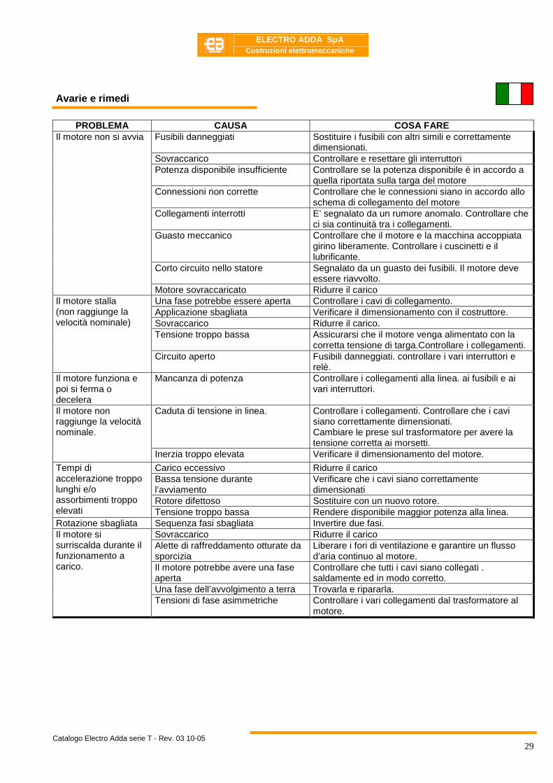
Avarie e rimedi
PROBLEMA CAUSA COSA FARE
Fusibili danneggiati Sostituire i fusibili con altri simili e correttamente dimensionati.
Sovraccarico Controllare e resettare gli interruttori Potenza disponibile insufficiente Controllare se la potenza disponibile è in accordo a
quella riportata sulla targa del motore Connessioni non corrette Controllare che le connessioni siano in accordo allo
schema di collegamento del motore Collegamenti interrotti E’ segnalato da un rumore anomalo. Controllare che
ci sia continuità tra i collegamenti. Guasto meccanico Controllare che il motore e la macchina accoppiata
girino liberamente. Controllare i cuscinetti e il lubrificante.
Corto circuito nello statore Segnalato da un guasto dei fusibili. Il motore deve essere riavvolto.
Il motore non si avvia
Motore sovraccaricato Ridurre il carico Una fase potrebbe essere aperta Controllare i cavi di collegamento. Applicazione sbagliata Verificare il dimensionamento con il costruttore. Sovraccarico Ridurre il carico. Tensione troppo bassa Assicurarsi che il motore venga alimentato con la
corretta tensione di targa.Controllare i collegamenti.
Il motore stalla (non raggiunge la velocità nominale)
Circuito aperto Fusibili danneggiati. controllare i vari interruttori e relè.
Il motore funziona e poi si ferma o decelera
Mancanza di potenza Controllare i collegamenti alla linea. ai fusibili e ai vari interruttori.
Caduta di tensione in linea. Controllare i collegamenti. Controllare che i cavi siano correttamente dimensionati. Cambiare le prese sul trasformatore per avere la tensione corretta ai morsetti.
Il motore non raggiunge la velocità nominale.
Inerzia troppo elevata Verificare il dimensionamento del motore.
Carico eccessivo Ridurre il carico Bassa tensione durante l’avviamento
Verificare che i cavi siano correttamente dimensionati
Rotore difettoso Sostituire con un nuovo rotore.
Tempi di accelerazione troppo lunghi e/o assorbimenti troppo elevati Tensione troppo bassa Rendere disponibile maggior potenza alla linea. Rotazione sbagliata Sequenza fasi sbagliata Invertire due fasi.
Sovraccarico Ridurre il carico Alette di raffreddamento otturate da sporcizia
Liberare i fori di ventilazione e garantire un flusso d’aria continuo al motore.
Il motore potrebbe avere una fase aperta
Controllare che tutti i cavi siano collegati . saldamente ed in modo corretto.
Una fase dell’avvolgimento a terra Trovarla e ripararla.
Il motore si surriscalda durante il funzionamento a carico.
Tensioni di fase asimmetriche Controllare i vari collegamenti dal trasformatore al motore.

ELECTRO ADDA SpA
Costruzioni elettromeccaniche
Catalogo Electro Adda serie T - Rev. 03 10-05
30
PROBLEMA CAUSA COSA FARE
Motore non allineato Allinearlo Basamento debole Rinforzare il basamento. Giunto non bilanciato Bilanciare il giunto Macchina accoppiata sbilanciata Bilanciare la macchina accoppiata. Cuscinetti difettosi Sostituire i cuscinetti. Pesi di bilanciatura allentati Bilanciare il rotore. Motore bilanciato diversamente dal giunto (mezza chiavetta – chiavetta intera)
Bilanciare il giunto o il motore
Motore trifase che funziona a fase singola
Controllare le fasi.
Il motore vibra
Gioco eccessivo Sostituire il cuscinetto. La ventola raschia il copriventola Eliminare il contatto. Rumore anomalo Basetta allentata Stringere le viti relative. Traferro non uniforme Controllare e correggere l’allineamento dei
cuscinetti. Rumorosità durante il funzionamento
Rotore non bilanciato Bilanciarlo. Albero piegato o incrinato Raddrizzare o sostituire l’albero. Trazione eccessiva delle cinghie Diminuire la tensione delle cinghie Pulegge troppo lontane dalla battuta dell’albero
Avvicinare la puleggia alla battuta del motore.
Diametro puleggia troppo piccolo Usare pulegge più grandi. Allineamento non corretto Correggere l’allineamento del motore e della
macchina accoppiata.
Sovraccarico del cuscinetto Controllare l’allineamento. e le eventuali spinte radiali e/o assiali.
Cuscinetti troppo caldi
Sfere o pista del cuscinetto rovinata Pulire accuratamente l’alloggiamento e sostituire il cuscinetto
Nel caso di anomalie o problemi relativi ai motori alimentati da inverter chiedere a ELECTRO ADDA SpA
ELECTRO ADDA SpA
Costruzioni elettromeccaniche
Catalogo Electro Adda serie T - Rev. 03 10-05
31
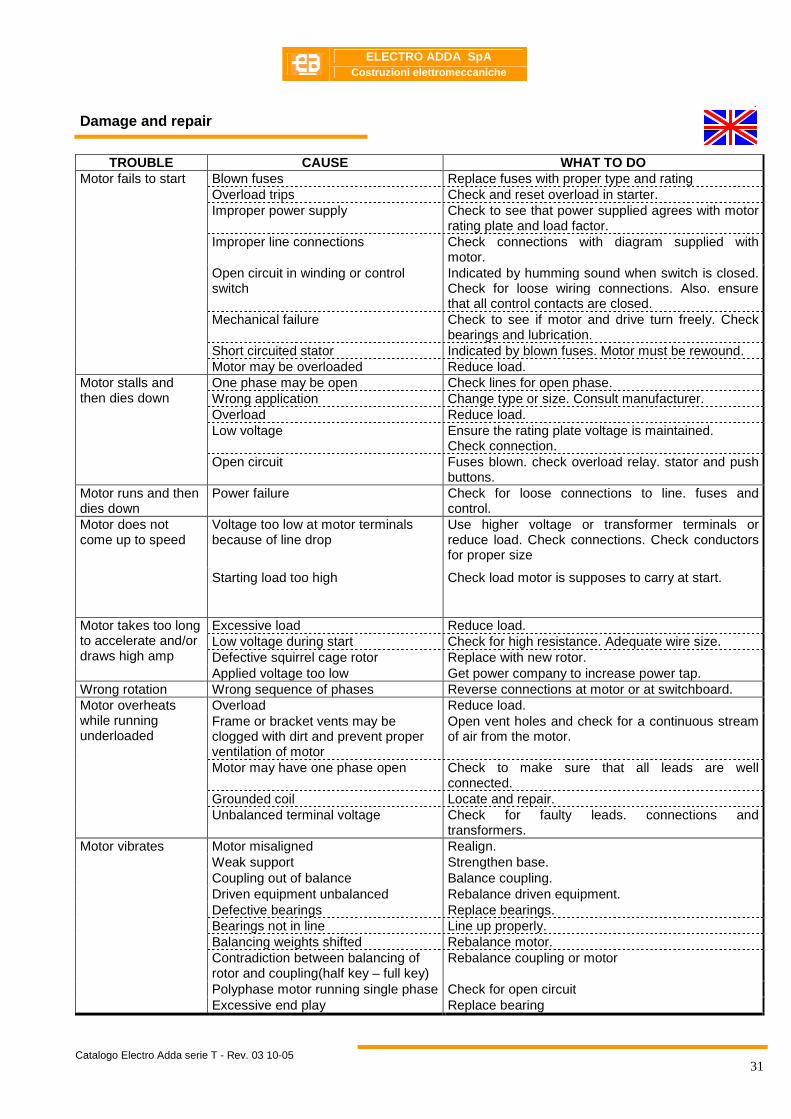
Damage and repair
TROUBLE CAUSE WHAT TO DO Blown fuses Replace fuses with proper type and rating Overload trips Check and reset overload in starter. Improper power supply Check to see that power supplied agrees with motor
rating plate and load factor. Improper line connections Check connections with diagram supplied with
motor. Open circuit in winding or control switch
Indicated by humming sound when switch is closed. Check for loose wiring connections. Also. ensure that all control contacts are closed.
Mechanical failure Check to see if motor and drive turn freely. Check bearings and lubrication.
Short circuited stator Indicated by blown fuses. Motor must be rewound.
Motor fails to start
Motor may be overloaded Reduce load. One phase may be open Check lines for open phase. Wrong application Change type or size. Consult manufacturer. Overload Reduce load. Low voltage Ensure the rating plate voltage is maintained.
Check connection.
Motor stalls and then dies down
Open circuit Fuses blown. check overload relay. stator and push buttons.
Motor runs and then dies down
Power failure Check for loose connections to line. fuses and control.
Voltage too low at motor terminals because of line drop
Use higher voltage or transformer terminals or reduce load. Check connections. Check conductors for proper size
Motor does not come up to speed
Starting load too high Check load motor is supposes to carry at start.
Excessive load Reduce load. Low voltage during start Check for high resistance. Adequate wire size. Defective squirrel cage rotor Replace with new rotor.
Motor takes too long to accelerate and/or draws high amp
Applied voltage too low Get power company to increase power tap. Wrong rotation Wrong sequence of phases Reverse connections at motor or at switchboard.
Overload Reduce load. Frame or bracket vents may be clogged with dirt and prevent proper ventilation of motor
Open vent holes and check for a continuous stream of air from the motor.
Motor may have one phase open Check to make sure that all leads are well connected.
Grounded coil Locate and repair.
Motor overheats while running underloaded
Unbalanced terminal voltage Check for faulty leads. connections and transformers.
Motor misaligned Realign. Weak support Strengthen base. Coupling out of balance Balance coupling. Driven equipment unbalanced Rebalance driven equipment. Defective bearings Replace bearings. Bearings not in line Line up properly. Balancing weights shifted Rebalance motor. Contradiction between balancing of rotor and coupling(half key – full key)
Rebalance coupling or motor
Polyphase motor running single phase Check for open circuit
Motor vibrates
Excessive end play Replace bearing
ELECTRO ADDA SpA
Costruzioni elettromeccaniche
Catalogo Electro Adda serie T - Rev. 03 10-05
32
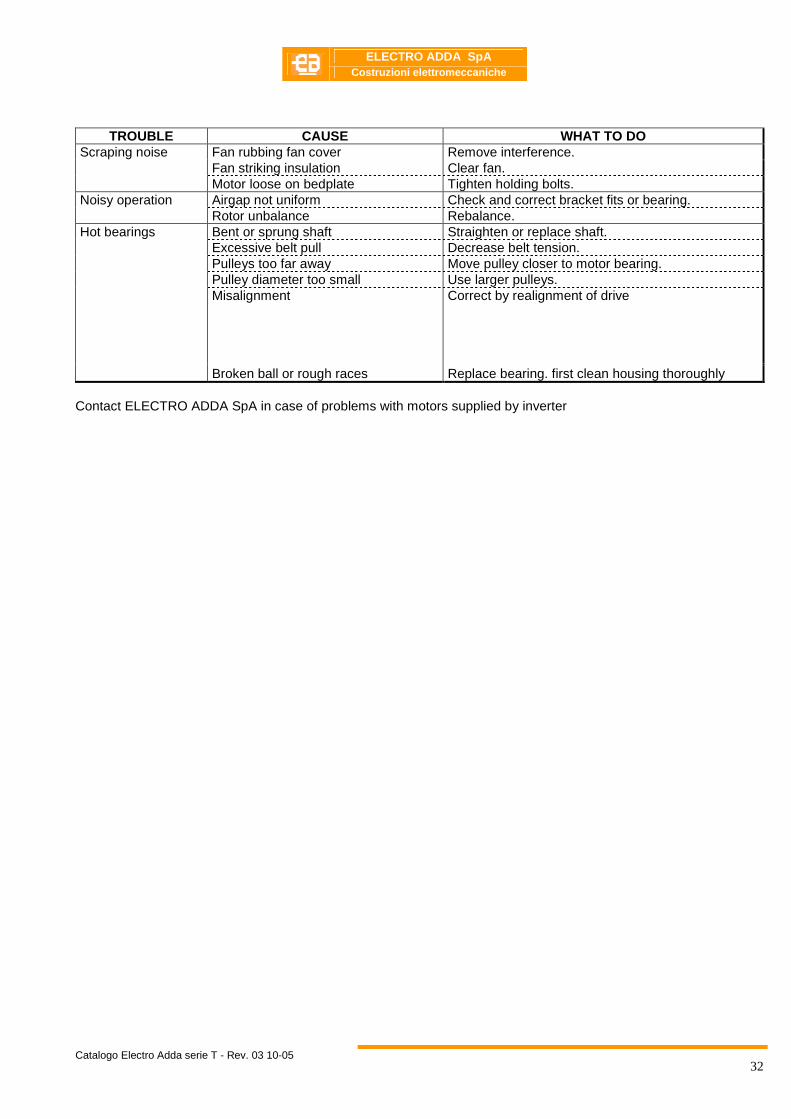
TROUBLE CAUSE WHAT TO DO Fan rubbing fan cover Remove interference. Fan striking insulation Clear fan.
Scraping noise
Motor loose on bedplate Tighten holding bolts. Airgap not uniform Check and correct bracket fits or bearing. Noisy operation Rotor unbalance Rebalance. Bent or sprung shaft Straighten or replace shaft. Excessive belt pull Decrease belt tension. Pulleys too far away Move pulley closer to motor bearing. Pulley diameter too small Use larger pulleys. Misalignment Correct by realignment of drive
Hot bearings
Broken ball or rough races Replace bearing. first clean housing thoroughly Contact ELECTRO ADDA SpA in case of problems with motors supplied by inverter
ELECTRO ADDA SpA
Costruzioni elettromeccaniche
Catalogo Electro Adda serie T - Rev. 03 10-05
33
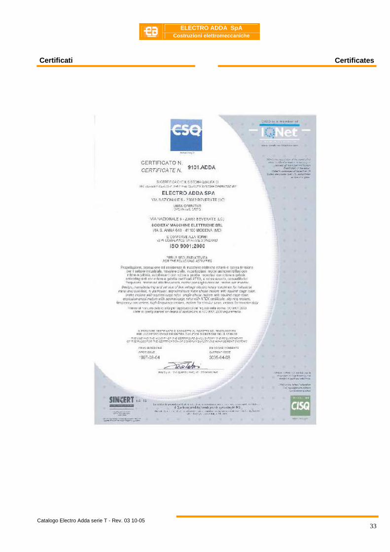
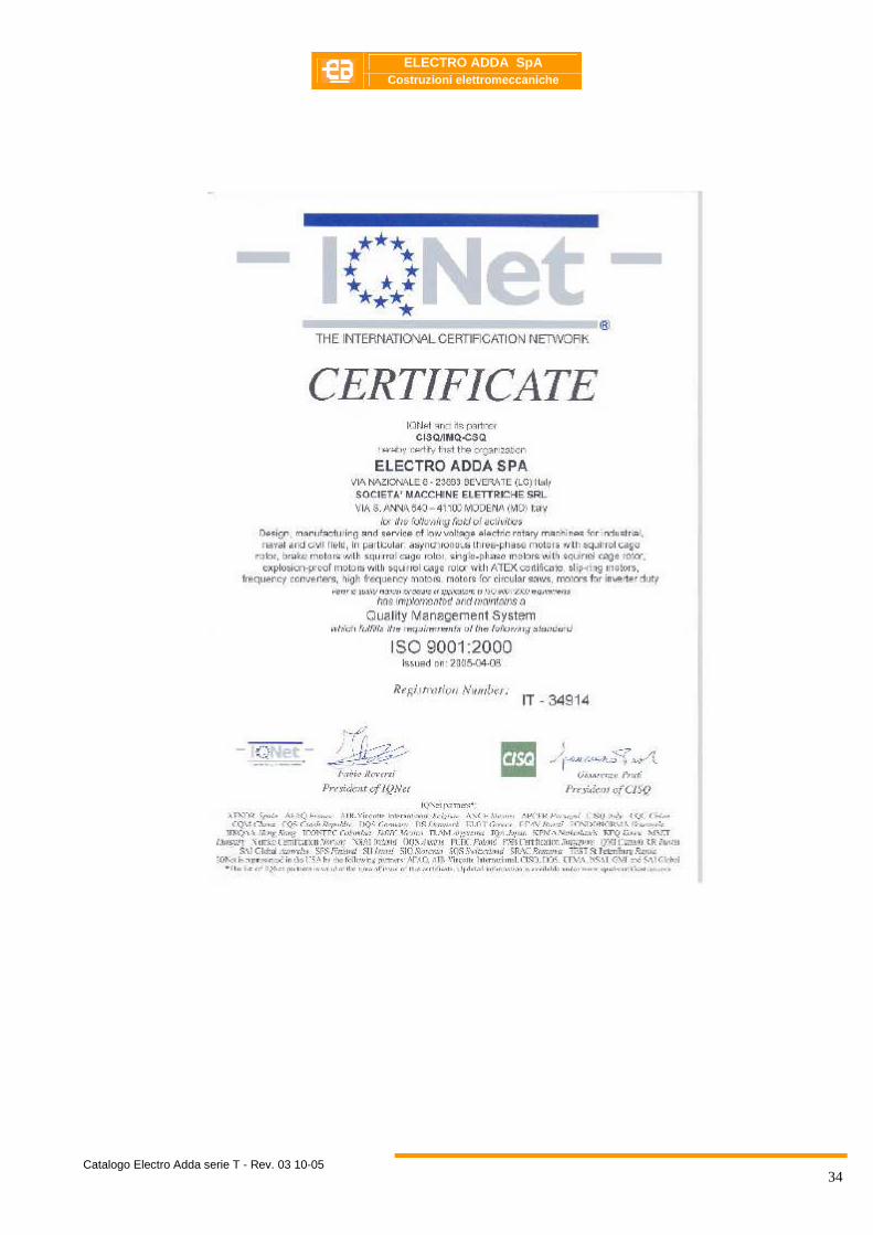
Certificati Certificates
ELECTRO ADDA SpA
Costruzioni elettromeccaniche
Catalogo Electro Adda serie T - Rev. 03 10-05
34
ELECTRO ADDA SpA
Costruzioni elettromeccaniche
Catalogo Electro Adda serie T - Rev. 03 10-05
35
Le caratteristiche tecniche. le dimensioni ed ogni altro dato di questo catalogo non sono impegnative. ELECTRO ADDA SpA si riserva il diritto di cambiarle in qualsiasi momento e senza preavviso
Technical features. dimensions. as well as any other data in this catalogue are not prescriptive. ELECTRO ADDA SpA reserves itself the right to change them at any time without giving any previous notice
ELECTRO ADDA SpA
Costruzioni elettromeccaniche
Catalogo Electro Adda serie T - Rev. 03 10-05
36
ELECTRO ADDA SPA
COSTRUZIONI ELETTROMECCANICHE
VIA NAZIONALE 8 - 23883 BEVERATE di BRIVIO LC – ITALY TELEFONO +39 039 53.20.621 FAX +39 039 53.21.335 www.electroadda.com - [email protected]
UNITÀ LOCALE MODENA: VIA SANT’ANNA 640
MODENA - MO- TELEFONO +39 059 45.21.32
FAX +39 059 45.21.58 [email protected]
ADDA ANTRIEBSTECHNIK GMBH MAX-PLANCK-STRASSE 2 D-63322 ROEDERMARK
TEL. +49 607491051 FAX +49 6074910520 www.electroadda.com - [email protected]