
DESING PROPOSAL OF A PLASTIC PANEL FOR SLABS …
103
DESING PROPOSAL OF A PLASTIC PANEL FOR SLABS FORMWORK DURING CONCRETE CASTING AND HARDENING Pablo Antonio Gelvez Munevar Matricola: 851688 Title to obtain: MSc. Design and Engineering L.M. Progetto e Ingegnerizzazione del Prodotto Industriale Relatore: Roberto Chiesa PhD Dipartamento di Chimica, Materiali e Ingegniernia Chimica “Giulio Natta” Desing School Milan, Italy A.Y. 2017 – 2018
Transcript of DESING PROPOSAL OF A PLASTIC PANEL FOR SLABS …
DESING PROPOSAL OF A PLASTIC PANEL FOR SLABS FORMWORK DURING CONCRETE CASTING AND HARDENING
Pablo Antonio Gelvez Munevar
Matricola: 851688
Title to obtain:
MSc. Design and Engineering L.M. Progetto e Ingegnerizzazione del Prodotto Industriale
Relatore:
Roberto Chiesa PhD Dipartamento di Chimica, Materiali e Ingegniernia Chimica “Giulio Natta”
Desing School
Milan, Italy
A.Y. 2017 – 2018


“Design is Everything” Paul Rand
A Dios, guía y protector.
A mis Padres por cada esfuerzo y todo su apoyo.
A mis hermanos Jorge y Mauricio por ser ejemplo que seguir.
A ti Yeimmy, por tu apoyo desinteresado.
A mis amigos del “International Students Office” del Politecnico di Milano,
por ser mi segunda familia en Italia.

Contents
Glossary .............................................................................................................................................13
INTRODUCTION ................................................................................................................................17
1. JUSTIFICATION ........................................................................................................................19
2. OBJECTIVES .............................................................................................................................20
2.1 PRIMARY OBJECTIVE ......................................................................................................20
2.2 SECONDARY OBJECTIVES .............................................................................................20
3. PROJECT METHODOLOGY .....................................................................................................21
3.1 Problem Analysis................................................................................................................22
3.1.1 Formwork for concrete ...............................................................................................22
3.1.3 Design criteria for formwork .......................................................................................25
3.2 Case of study: Social Interest Housing projects. ...............................................................27
3.2.1 House type: Two levels House ..................................................................................28
3.3 Plastic processing methods. ..............................................................................................30
3.4 Background ........................................................................................................................31
3.5 Problem establishment. ......................................................................................................32
3.6 Bench Marking. ..................................................................................................................33
3.7 Design Parameters ............................................................................................................37
3.7.1 Dimensions establishment. ........................................................................................37
3.7.2 Number of components ..............................................................................................38
3.7.3 Concrete reaction un the pouring processes. ............................................................40
3.7.4 Calculation of slab load ..............................................................................................41
3.7.5 Calculation of critical deformation ..............................................................................43
4. CONCEPT ..................................................................................................................................46
4.1 Ideation process .................................................................................................................46
4.1.1 Plastic sheet semblable panels: .................................................................................46
4.1.2 Plastic panel for columns and walls formwork: ..........................................................47
4.1.3 Prefabricated concrete beams: ..................................................................................48
4.1.4 Plastic-wood flooring: .................................................................................................48
4.1.5 Frame beams: ............................................................................................................49
4.1.6 Metal deck: .................................................................................................................50
4.1.7 Bridge’s structure: ......................................................................................................50
4.1.8 Handmade wood panel: .............................................................................................51
4.2 Profile abstraction ..............................................................................................................51
4.3 Design alternatives .............................................................................................................53
4.3.1 Piles plus Frame beams plus metal deck modules (P+B+M) ....................................53
4.3.2 Plastic modules for columns and wall forms (Pm) .....................................................54
4.3.3 Bridge’s structure (Bs) ................................................................................................55
4.3.4 Wood handmade panel plus Prefabricated beams (W+P) .........................................56
4.4 Final profiles and 3D modelling ..........................................................................................57
4.4.1 Simulation ...................................................................................................................58
4.5 Concept selection ...............................................................................................................63
5. DETAIL DESIGN ........................................................................................................................64
5.1 Uniform wall thickness .......................................................................................................64
5.2 Sharp vortices avoiding ......................................................................................................64
5.3 Hollows ...............................................................................................................................64
5.4 Reinforcement and wall thickness re-design .....................................................................65
5.5 Material selection process ..................................................................................................68
5.6 Rigidity improvement ..........................................................................................................72
5.7 Panel approximated production costing per square meter ................................................75
6. CONCLUSIONS .........................................................................................................................77
6.1 Limitations ..........................................................................................................................78

6.2 Future work ........................................................................................................................78
List of figures
Fig. 1 Product development process(Ulrich & Eppinger, 2009) ........................................................................ 21
Fig. 2 Planning step(Ulrich & Eppinger, 2009) .................................................................................................. 21
Fig. 3 Formwork system(Johnston, 2010) ......................................................................................................... 22
Fig. 4 Types of formwork: (a) Foundations; (b) Walls; (c) Columns (Johnston, 2010) ...................................... 24
Fig. 5 Concrete Slab formwork system (Author) ............................................................................................... 25
Fig. 6 Social Interest Housing project (Chachareros, 2015) .............................................................................. 27
Fig. 7 Typical SIH distribution (Gelvez, 2017) ................................................................................................... 28
Fig. 8 Handmade wood board (Author) ............................................................................................................ 37
Fig. 9 Pressures on formwork: (a) Concrete pressure on slab; (b) Lateral pressure on svelte elements (Author)
........................................................................................................................................................................... 40
Fig. 10 Lighten slab scheme (Gelvez, 2017) ...................................................................................................... 42
Fig. 11 Sheathing setting for maximum allowed deformation on load diagram (Author) ............................... 44
Fig. 12 Plastic sheet semblable panel (Plasticpiling.co, 2016) .......................................................................... 46
Fig. 13 Plastic panel SBS (DSCAFF, 2017) .......................................................................................................... 47
Fig. 14 Prefabricated beams (Precast, 2017).................................................................................................... 48
Fig. 15 Plastic - Wood Flooring modules (Alibaba, 2018) ................................................................................. 48
Fig. 16 Frame beams geometry (PBS, 2015) ..................................................................................................... 49
Fig. 17 Metal Deck module (CORDECK, 2017) .................................................................................................. 50
Fig. 18 Tilos la Palma bridge (lower arc structure) (Wikipedia, 2018) .............................................................. 50
Fig. 19 Handmade wood panel (Author) .......................................................................................................... 51
Fig. 20 Profiles abstraction (Author) ................................................................................................................ 52
Fig. 21 Concept A (Author) ............................................................................................................................... 53
Fig. 22 Combined profiles for alternative A. (Author) ....................................................................................... 53
Fig. 23 Concept B. (Author)............................................................................................................................... 54
Fig. 24 Profile for alternative B. (Author) ......................................................................................................... 54
Fig. 25 Concept C. (Author) ............................................................................................................................... 55
Fig. 26 Profile for concept C. (Author) .............................................................................................................. 55
Fig. 27 Concept D. (Author) .............................................................................................................................. 56
Fig. 28 Combined profiles for alternative D. (Author) ...................................................................................... 56
Fig. 29 3D modelling concept A (Author) .......................................................................................................... 57
Fig. 30 3D modelling concept B (Author) .......................................................................................................... 57
Fig. 31 3D modelling concept C (Author) .......................................................................................................... 58
Fig. 32 3D modelling concept D (Author) ......................................................................................................... 58
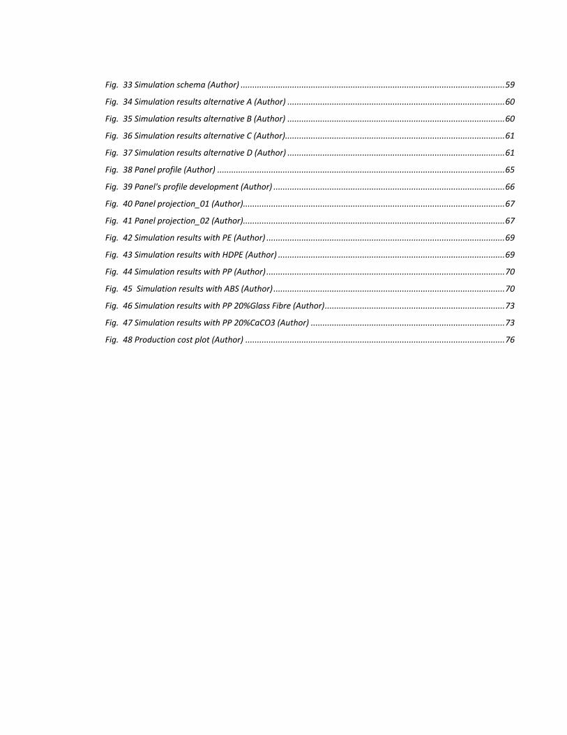
Fig. 33 Simulation schema (Author) ................................................................................................................. 59
Fig. 34 Simulation results alternative A (Author) ............................................................................................. 60
Fig. 35 Simulation results alternative B (Author) ............................................................................................. 60
Fig. 36 Simulation results alternative C (Author) .............................................................................................. 61
Fig. 37 Simulation results alternative D (Author) ............................................................................................. 61
Fig. 38 Panel profile (Author) ........................................................................................................................... 65
Fig. 39 Panel's profile development (Author) ................................................................................................... 66
Fig. 40 Panel projection_01 (Author) ................................................................................................................ 67
Fig. 41 Panel projection_02 (Author) ................................................................................................................ 67
Fig. 42 Simulation results with PE (Author) ...................................................................................................... 69
Fig. 43 Simulation results with HDPE (Author) ................................................................................................. 69
Fig. 44 Simulation results with PP (Author) ...................................................................................................... 70
Fig. 45 Simulation results with ABS (Author) ................................................................................................... 70
Fig. 46 Simulation results with PP 20%Glass Fibre (Author) ............................................................................. 73
Fig. 47 Simulation results with PP 20%CaCO3 (Author) ................................................................................... 73
Fig. 48 Production cost plot (Author) ............................................................................................................... 76
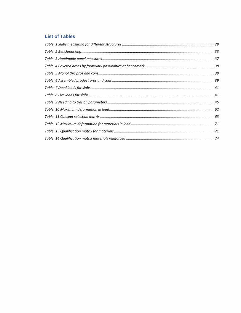
List of Tables
Table. 1 Slabs measuring for different structures ............................................................................................. 29
Table. 2 Benchmarking ...................................................................................................................................... 33
Table. 3 Handmade panel measures ................................................................................................................. 37
Table. 4 Covered areas by formwork possibilities at benchmark ...................................................................... 38
Table. 5 Monolithic pros and cons ..................................................................................................................... 39
Table. 6 Assembled product pros and cons ....................................................................................................... 39
Table. 7 Dead loads for slabs............................................................................................................................. 41
Table. 8 Live loads for slabs ............................................................................................................................... 41
Table. 9 Needing to Design parameters ............................................................................................................ 45
Table. 10 Maximum deformation in load .......................................................................................................... 62
Table. 11 Concept selection matrix ................................................................................................................... 63
Table. 12 Maximum deformation for materials in load .................................................................................... 71
Table. 13 Qualification matrix for materials ..................................................................................................... 71
Table. 14 Qualification matrix materials reinforced ......................................................................................... 74


Glossary
Formwork: It is temporary or permanent moulds into which concrete or similar materials are poured.
In the context of concrete construction, the falsework supports the shuttering moulds.
Concrete: A very hard building material made by mixing together cement, sand, small stones and
water.
Slab: A thick, flat piece of a solid substance, such as concrete, stone, wood, metal that is usually
square or rectangular.
Column: It is a structural member designed to carry compressive loads, composed of concrete with
an embedded steel frame to provide reinforcement.
Beam: It is a structural element that primarily resists loads applied laterally to the beam's axis.
Extrusion: Isis a process used to create objects of a fixed cross-sectional profile. A material is
pushed through a die of the desired cross-section.
Polymer: Is a large molecule, or macromolecule composed of many repeated subunits. Most
manufactured polymers are thermoplastic. This property allows for easy processing and facilitates
recycling.
Yield Strength: is the maximum stress that can be applied along its axis before it begins to change
shape.
14
RESUME
Inside the building field, specifically in the Colombian Social Housing (SH), structural designs are
realized to edification of family houses which are composed by two levels and on the construction
process, it is necessary to use formwork for concrete.
Formwork is used elements to mould reinforced concrete either cylinder or prismatic or cylindrical
shapes regarding planned designs. Those elements are designed to support applied pressures by
concrete on casting and later hardening. Division slabs are moulded by panels which commonly are
made of leftover wood such pine or metallic materials such as steel or aluminium. Also, nowadays
those panels are producing polymers like Polypropylene (PP), Acrylonitrile-Butadiene-Styrene (ABS)
and composites material of Polyethylene (PE) plus Glass fibre. However, rustic material panels could
present inconvenient at certain times since the concrete sticks on if formwork is not coated with petrol.
Also, panels can present damages in their components at disassembling, so, in consequence, it is
necessary to do maintenance.
The project's objective is to do a design proposal of a polymeric panel which is on the capacity to
support applied pressures by fresh concrete at the pouring of division slabs for SH of two levels,
avoiding components' damages because of dismemberment and necessary maintenance after each
use.
At the end of the process, it is hoping to arrive at a projected panel to be produced by plastic extrusion
method that is being selected following established parameters to piece design, which is parametrized
in CAD/CAF and to do the applied pressure simulation by concrete and following analysis of possible
polymeric materials according to results.
Keywords: slab mould, plastic panel, formwork, polymer, extrusion
15
RIASSUNTO
All'interno del campo edilizio, in particolare nel Social Housing (SH) colombiano, sono realizzati
progetti strutturali per l'edificazione di case familiari che sono composte da due livelli e nel processo
di costruzione, è necessario utilizzare casseforme per calcestruzzo.
Le casseforme sono elementi utilizzati per modellareil cemento armato sia cilindriche che forme
prismatiche rispetto ai progetti pianificati. Questi elementi sono progettati per supportare le pressioni
applicate dal calcestruzzo alla fusione e successivamente all'indurimento. Le lastre divisorie sono
modellate da pannelli che sono comunemente fatti di legno rimasto e materiali metallici come acciaio
o alluminio. Inoltre, al giorno d'oggi quei pannelli sono prodotti di polimeri come polipropilene (PP),
acrilonitrile-butadiene-stirene (ABS) e materiali compositi di polietilene (PE) più fibra di vetro.
Comunque, i pannelli di materiali rustici potrebbero presentare inconvenienti in determinati momenti
poiché il calcestruzzo si incolla se la cassaforma non è rivestita di benzina. Inoltre, pannelli sofrono
danni nei loro componenti allo smontaggio, quindi, di conseguenza è necessario fare manutenzione.
L'obiettivo del progetto è quello di progettare una proposta per un pannello polimerico che sia in grado
di supportare pressioni applicate da calcestruzzo fresco a colata di lastre divisorie per SH di due
livelli, evitando i danni dei componenti a causa dello smembramento e della manutenzione necessaria
dopo ogni utilizzo.
Alla fine del processo, si spera di arrivare a un pannello progettato per essere prodotto da un metodo
di estrusione di plastica che viene selezionato in base ai parametri per la progettazione,
parametrizzata in CAD / CAF e alla simulazione di pressione applicata da calcestruzzo e dopo l'analisi
di possibili materiali polimerici in base ai risultati.
Parole chiave: stampo per lastre, pannello in plastica, cassaforma, polimero, estrusione

16
17
INTRODUCTION
Inside the housing construction, it is realized the structural manufacture where moulds are used to
contains and give self to columns, beams and slabs. Those elements are considered the main
components of the building. Structure manufacturing is realized following steps: reinforcement
assembling, formwork installation, concrete pouring, concrete hardening and finally formwork
disassembling. At the moulds installation stage, supports, beams, joists, anchors and sheathing
components are placed to contain concrete.
At slab formwork placement, a series of components are assembled to support fresh concrete to
mould and create the division of house levels. Sheathing is an industrialized metallic or wooden panel.
It is the closest component to concrete, so, these is on direct contact with poured material, generating
the slab self. In addition, it is transferring pressure which is produced by cement to support
components of the formwork. Nevertheless, there are handmade panels at Colombian far away
regions from main cities. Those moulds are assembled of discard battens which can present
inconvenient when plyboards are in contact whit concrete such as stuck, dismemberment and total
disassembling. So, it is necessary to do maintenance on panels or throw away damaged goods.
Currently, the are products for formwork according to presented needs in work out. It is possible to
find plyboards with different measures and materials composition. Meva (MEVA, 2017) company is
presenting a hybrid panel which is composed by Aluminium frame and Polypropylene board, it is a
light sheathing part and avoid concrete stuck in its face. Topec® is formwork line from Hunnebeck
(Hunnebeck, 2017) company. This module is combined Aluminium framing whit wood as sheath part.
Regarding to current solutions, those are improving the formwork performance, but goods are offered
in main cities of the country.
Concerning to the previous expressed matters, it is proposed a design of a plastic panel for slab
formwork for concrete casting and hardening. It is given a solution to avoid different inconvenient at
work out and improving panel characteristics regarding to concrete finishing, modularity and material
for production.
Project methodology is following the proposed process by Karl T. Ulrich and Steven D. Eppinger
called “Product Design and Development” in which first step is to realize an analysis of current
problem through literature revision in scientific papers and books regarding formwork design and
structures construction, also interviews are made with workers and experts to collect opinions and
direct needs coming out from the daily users of those products. Then, design requirements are
18
established from the got information which is the starting point for the design proposal for the plastic
panel.
Second step is driven to product ideation. Current moulds are analysed in a benchmarking to produce
initial concepts to find possible solutions referring to previous established problems and needs.
Conceptions are evaluated in a matrix when weakness are noticed. These contains design
parameters, each one has a quantitative score. After qualification it is selected the best concept. It is
carry out to next step where is done the detailed design.
Detailed design is executed considering the product that is being proposed. Following production
processing and materials literature, the product design improvement is realised. Also, panel’s profile
and fabrication process are set up. After that, final design proposal is showed and defined for the
plastic panel for slab formwork.
The final step of the project is to validate and compare the design proposal through CAD/CAM tools.
To effectuate qualitative and quantitative validations product 3D model is tested in a simulation at
Solidworks® software. Also, at the end of the process it is carry out a costing analysis of the piece
for a future production. It is done in CES Edupack software.
19
1. JUSTIFICATION
Into the construction field, it is done housing structural manufacturing by formwork to produce
columns, beams and slabs. In Colombia and specifically in faraway regions from main cities
handmade formwork is used to construct those important components of a house. Commonly, panels
are made of leftover wood which can generate inconvenient such as concrete stuck or
dismemberment at the removal step.
In those regions Social Housing has got popularity and projects to build residential zones have
increased by the time (DANE, 2016), those projects can reach at least 100 houses, so, it is necessary
to provide elements for construction to the workout such formwork for concrete to build structural
components. In the market there are moulding systems which can assist in the forming of columns,
beams and slabs construction, but in general, it is not possible to rent those because of geographical
position of building plan. Then, the implemented solution by workers has been to used wood planks
to mould columns and beams and assembled panels to produce slabs. This panel is in direct contact
with fresh concrete and support it from the casting to the hardening. Nevertheless, those plyboards
present problems regarding to the disassembling step as it was told before. In addition, as panels
must be used several times to cast slabs, it is necessary to do maintenance anytime it is dismounted
from the slab to remove concrete stuck and to fix or change damaged lumbers of the panel.
Furthermore, environmental factors are affecting the material; those can rut panel’s components and
damages on itself if these are not coated with oil or a chemical substance to protect against those
factors.
So, after the problem analysis, it is the opportunity to take advantage of the technologies which can
give a support in the implementation of a plastic panel to offer a solution for those inconvenient at
workout in those regions. It is used the knowledge about plastic processing and production to
generate an alternative which can be manufactured and transported to those far zones and
implemented to avoid common difficulties with keeping handmade plyboards.
20
2. OBJECTIVES
2.1 PRIMARY OBJECTIVE
Realize the design proposal of a plastic panel for slab concrete casting and hardening through
literature and workout problems analysis as well as product conception methodology to make it more
efficient the social housing construction at faraway regions in Colombia.
2.2 SECONDARY OBJECTIVES
• Analyse concrete slab construction variables for Social Housing through bibliography
research and interviews with workers and experts to stablish product’s design parameters.
• Design proposal of a plastic panel for slab formwork for concrete.
• Evaluate the design proposal with CAD/CAM to determine product requirements
accomplishment.
• Do a qualitative comparison between the proposal and current handmade and industrial
products for formwork to determine design pros and improvements.
21
3. PROJECT METHODOLOGY
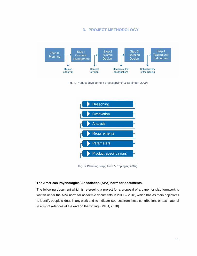
Fig. 1 Product development process(Ulrich & Eppinger, 2009)
Fig. 2 Planning step(Ulrich & Eppinger, 2009)
The American Psychological Association (APA) norm for documents.
The following document which is refereeing a project for a proposal of a panel for slab formwork is
written under the APA norm for academic documents in 2017 – 2018, which has as main objectives
to identify people’s ideas in any work and to indicate sources from those contributions or text material
in a list of refences at the end on the writing. (MRU, 2018)
22
3.1 Problem Analysis
3.1.1 Formwork for concrete
Formwork is defined as a temporary structure whose purpose is to provide support and
containment for fresh concrete until it can support itself. It moulds concrete according to design
sizes and shape, controlling position and alignment. (Hanna, 1999)
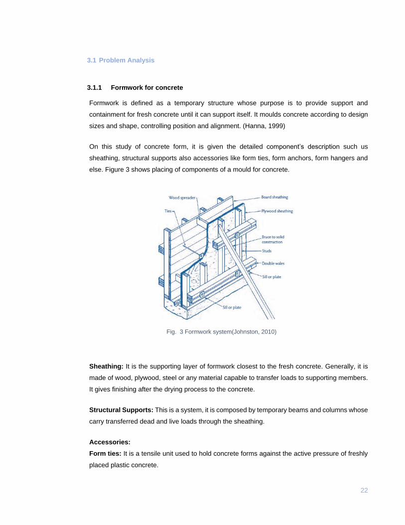
On this study of concrete form, it is given the detailed component’s description such us
sheathing, structural supports also accessories like form ties, form anchors, form hangers and
else. Figure 3 shows placing of components of a mould for concrete.
Fig. 3 Formwork system(Johnston, 2010)
Sheathing: It is the supporting layer of formwork closest to the fresh concrete. Generally, it is
made of wood, plywood, steel or any material capable to transfer loads to supporting members.
It gives finishing after the drying process to the concrete.
Structural Supports: This is a system, it is composed by temporary beams and columns whose
carry transferred dead and live loads through the sheathing.
Accessories:
Form ties: It is a tensile unit used to hold concrete forms against the active pressure of freshly
placed plastic concrete.
23
Form anchors: Those are devices used to secure formwork previously placed concrete during
pouring. They give to system the adequate strength.
Form hangers: Devices used to suspend formwork loads from structural steel, precast concrete
or other system members.
Side form spaces: Devices that keep the desire distances between a vertical form and
reinforcing bars.
The building requires formwork to support the slabs and footings or foundations which are
considered as horizontal forms, also columns, beams and walls whose are considered vertical
moulding. On the building field, there are different two different techniques used to construct
those forming systems: hand-set and crane set.(Hanna, 1999)
Hand-set system: It is called conventional system too. This is still the most common and popular
formwork systems because it is fabricated for the specific need of the slab, it means that is
assembled with wood beams and ribbons. However, this system sometimes becomes in a high
and expensive labour.
Crane-set: It is also called nonconventional method consist in modular panels which are faster
assembled and disassembled for forming. That system has increased by the time because
facilities in construction cycle, low cost and less time labour.
3.1.2 Horizontal forms:
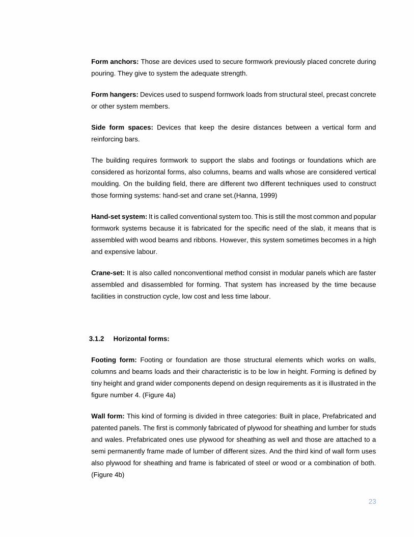
Footing form: Footing or foundation are those structural elements which works on walls,
columns and beams loads and their characteristic is to be low in height. Forming is defined by
tiny height and grand wider components depend on design requirements as it is illustrated in the
figure number 4. (Figure 4a)
Wall form: This kind of forming is divided in three categories: Built in place, Prefabricated and
patented panels. The first is commonly fabricated of plywood for sheathing and lumber for studs
and wales. Prefabricated ones use plywood for sheathing as well and those are attached to a
semi permanently frame made of lumber of different sizes. And the third kind of wall form uses
also plywood for sheathing and frame is fabricated of steel or wood or a combination of both.
(Figure 4b)
24
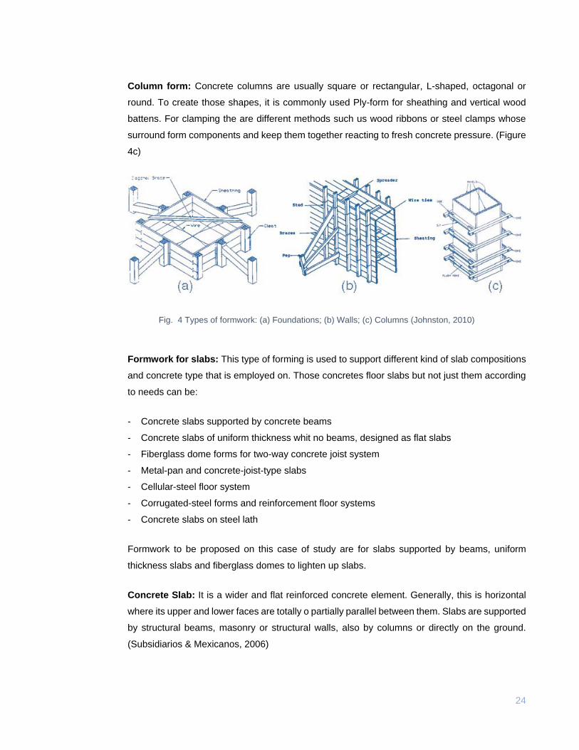
Column form: Concrete columns are usually square or rectangular, L-shaped, octagonal or
round. To create those shapes, it is commonly used Ply-form for sheathing and vertical wood
battens. For clamping the are different methods such us wood ribbons or steel clamps whose
surround form components and keep them together reacting to fresh concrete pressure. (Figure
4c)
Fig. 4 Types of formwork: (a) Foundations; (b) Walls; (c) Columns (Johnston, 2010)
Formwork for slabs: This type of forming is used to support different kind of slab compositions
and concrete type that is employed on. Those concretes floor slabs but not just them according
to needs can be:
- Concrete slabs supported by concrete beams
- Concrete slabs of uniform thickness whit no beams, designed as flat slabs
- Fiberglass dome forms for two-way concrete joist system
- Metal-pan and concrete-joist-type slabs
- Cellular-steel floor system
- Corrugated-steel forms and reinforcement floor systems
- Concrete slabs on steel lath
Formwork to be proposed on this case of study are for slabs supported by beams, uniform
thickness slabs and fiberglass domes to lighten up slabs.
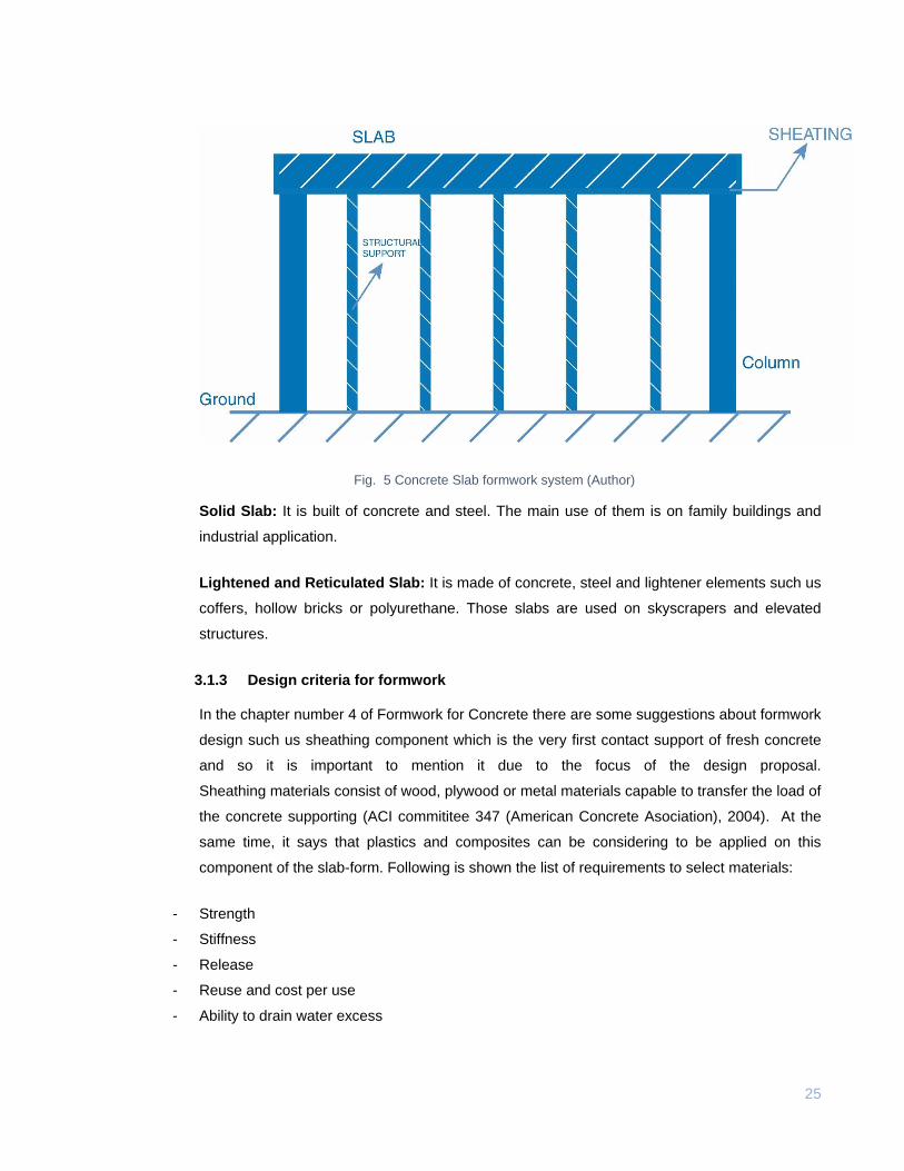
Concrete Slab: It is a wider and flat reinforced concrete element. Generally, this is horizontal
where its upper and lower faces are totally o partially parallel between them. Slabs are supported
by structural beams, masonry or structural walls, also by columns or directly on the ground.
(Subsidiarios & Mexicanos, 2006)
25
Fig. 5 Concrete Slab formwork system (Author)
Solid Slab: It is built of concrete and steel. The main use of them is on family buildings and
industrial application.
Lightened and Reticulated Slab: It is made of concrete, steel and lightener elements such us
coffers, hollow bricks or polyurethane. Those slabs are used on skyscrapers and elevated
structures.
3.1.3 Design criteria for formwork
In the chapter number 4 of Formwork for Concrete there are some suggestions about formwork
design such us sheathing component which is the very first contact support of fresh concrete
and so it is important to mention it due to the focus of the design proposal.
Sheathing materials consist of wood, plywood or metal materials capable to transfer the load of
the concrete supporting (ACI commititee 347 (American Concrete Asociation), 2004). At the
same time, it says that plastics and composites can be considering to be applied on this
component of the slab-form. Following is shown the list of requirements to select materials:
- Strength
- Stiffness
- Release
- Reuse and cost per use
- Ability to drain water excess
26
- Resistance to mechanical damage
- Workability
- Adaptability to environmental factors
Materials specification
Following instruction from ACI-347 manual (ACI 347, 2004), those are materials with their
specifications to be used in the formwork making off:
- Sawn lumber: For components such as framing, sheathing and shoring.
- Plywood: For sheathing and shoring.
- Steel: Panel framing and bracing: Heavy forms and falseworks; Columns and joist forms: Stay
in place deck forms shoring.
- Aluminum: Form panels and form framing members.
- Reconstructed wood panel: Form liners and sheathing.
- Wood fiber or Glass fiber: Stay in place form liners and sheathing.
- Laminated paper or fiber: Colum and beams forms. Forms for slabs beams and pre-cast piles.
- Corrugated cardboard: Internal forms in beams and girders (Generally this is used internal
shape call “egg-crate” stiffeners.)
27
3.2 Case of study: Social Interest Housing projects.
In Colombia, according to National Department of Statistics DANE by its acronym in Spanish, in
the last years, family buildings has increased in a 13,3% (DANE, 2017). Construction field has
put its interest on Social Housing (SH), that is a government system to give economy assistance
to buy a house by a family or workers and which has getting popularity because same given
benefits for. By the third quarter of 2017, according to DANE there were 3.994 SH on
construction process and 3.900 not SH too(DANE, 2017), so, it is interesting to have a look of
how those kind of hoses are built and which tools are implemented into the construction area to
fabricate slabs and others structural components of it.
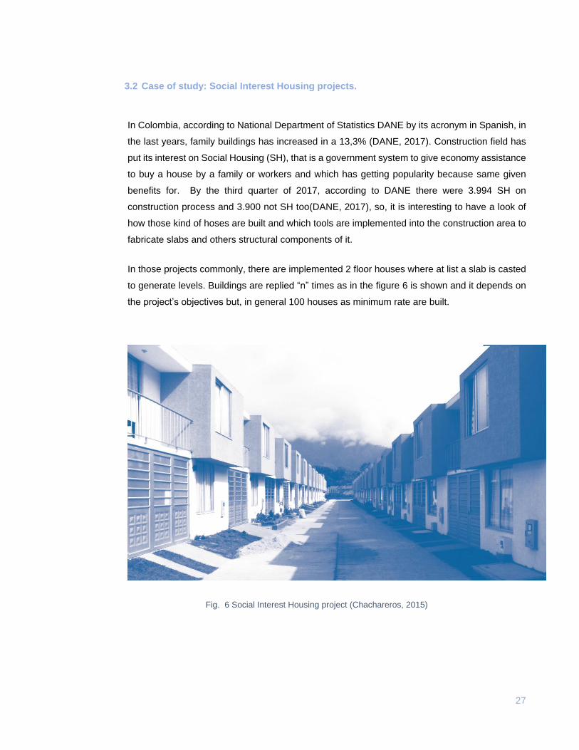
In those projects commonly, there are implemented 2 floor houses where at list a slab is casted
to generate levels. Buildings are replied “n” times as in the figure 6 is shown and it depends on
the project’s objectives but, in general 100 houses as minimum rate are built.
Fig. 6 Social Interest Housing project (Chachareros, 2015)
28
3.2.1 House type: Two levels House
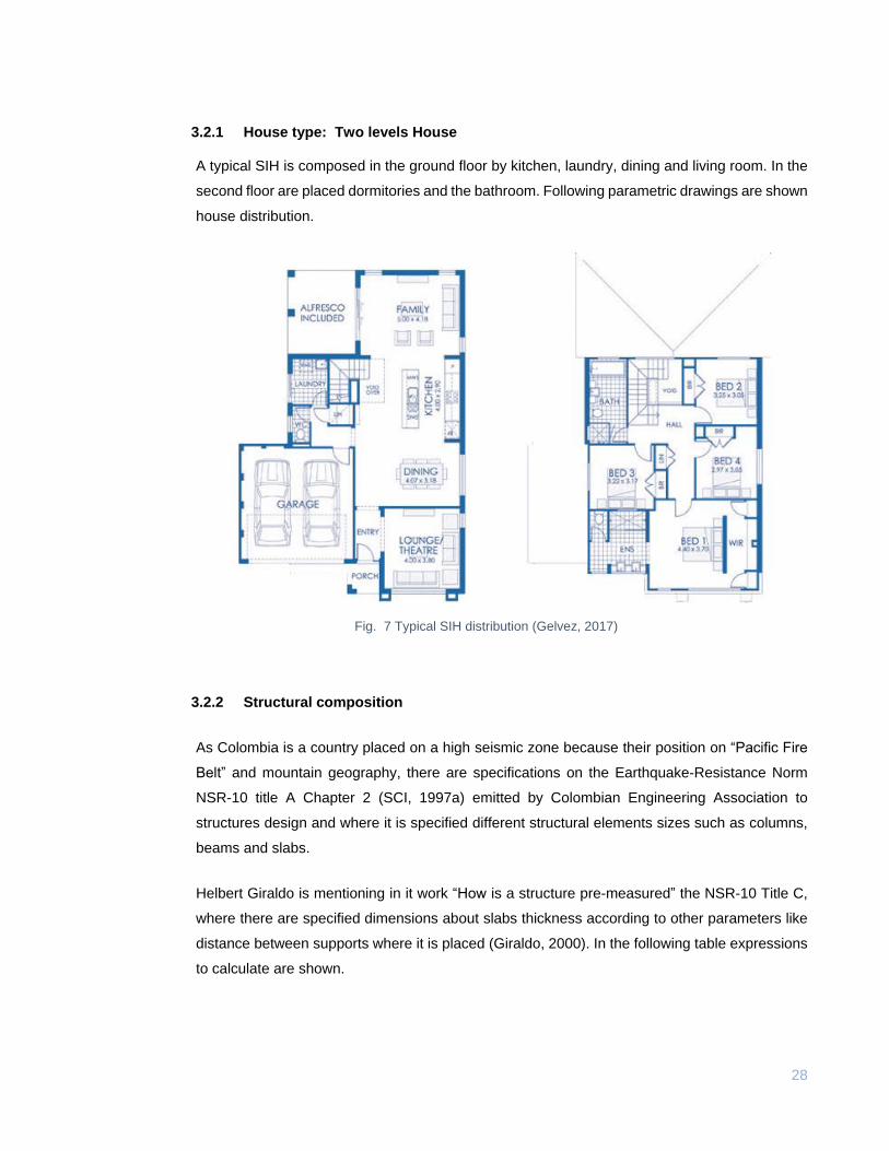
A typical SIH is composed in the ground floor by kitchen, laundry, dining and living room. In the
second floor are placed dormitories and the bathroom. Following parametric drawings are shown
house distribution.
Fig. 7 Typical SIH distribution (Gelvez, 2017)
3.2.2 Structural composition
As Colombia is a country placed on a high seismic zone because their position on “Pacific Fire
Belt” and mountain geography, there are specifications on the Earthquake-Resistance Norm
NSR-10 title A Chapter 2 (SCI, 1997a) emitted by Colombian Engineering Association to
structures design and where it is specified different structural elements sizes such as columns,
beams and slabs.
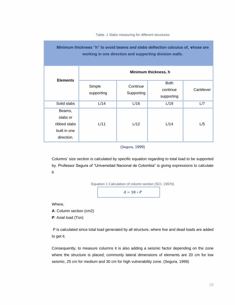
Helbert Giraldo is mentioning in it work “How is a structure pre-measured” the NSR-10 Title C,
where there are specified dimensions about slabs thickness according to other parameters like
distance between supports where it is placed (Giraldo, 2000). In the following table expressions
to calculate are shown.
29
Table. 1 Slabs measuring for different structures
Minimum thickness “h” to avoid beams and slabs deflection calculus of, whose are
working in one direction and supporting division walls.
Elements
Minimum thickness, h
Simple
supporting
Continue
Supporting
Both
continue
supporting
Cantilever
Solid slabs L/14 L/16 L/19 L/7
Beams,
slabs or
ribbed slabs
built in one
direction.
L/11
L/12
L/14 L/5
(Segura, 1999)
Columns’ size section is calculated by specific equation regarding to total load to be supported
by. Professor Segura of “Universidad Nacional de Colombia” is giving expressions to calculate
it
Equation 1 Calculation of column section (SCI, 1997b)
𝑨 = 𝟏𝟖 ∗ 𝑷
Where,
A: Column section (cm2)
P: Axial load (Ton)
P is calculated since total load generated by all structure, where live and dead loads are added
to get it.
Consequently, to measure columns it is also adding a seismic factor depending on the zone
where the structure is placed; commonly lateral dimensions of elements are 20 cm for low
seismic, 25 cm for medium and 30 cm for high vulnerability zone. (Segura, 1999)
30
3.3 Plastic processing methods.
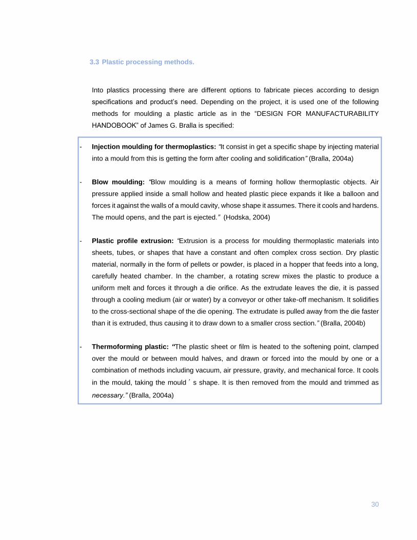
Into plastics processing there are different options to fabricate pieces according to design
specifications and product’s need. Depending on the project, it is used one of the following
methods for moulding a plastic article as in the “DESIGN FOR MANUFACTURABILITY
HANDOBOOK” of James G. Bralla is specified:
- Injection moulding for thermoplastics: “It consist in get a specific shape by injecting material
into a mould from this is getting the form after cooling and solidification” (Bralla, 2004a)
- Blow moulding: “Blow moulding is a means of forming hollow thermoplastic objects. Air
pressure applied inside a small hollow and heated plastic piece expands it like a balloon and
forces it against the walls of a mould cavity, whose shape it assumes. There it cools and hardens.
The mould opens, and the part is ejected.” (Hodska, 2004)
- Plastic profile extrusion: “Extrusion is a process for moulding thermoplastic materials into
sheets, tubes, or shapes that have a constant and often complex cross section. Dry plastic
material, normally in the form of pellets or powder, is placed in a hopper that feeds into a long,
carefully heated chamber. In the chamber, a rotating screw mixes the plastic to produce a
uniform melt and forces it through a die orifice. As the extrudate leaves the die, it is passed
through a cooling medium (air or water) by a conveyor or other take-off mechanism. It solidifies
to the cross-sectional shape of the die opening. The extrudate is pulled away from the die faster
than it is extruded, thus causing it to draw down to a smaller cross section.” (Bralla, 2004b)
- Thermoforming plastic: “The plastic sheet or film is heated to the softening point, clamped
over the mould or between mould halves, and drawn or forced into the mould by one or a
combination of methods including vacuum, air pressure, gravity, and mechanical force. It cools
in the mould, taking the mould’s shape. It is then removed from the mould and trimmed as
necessary.” (Bralla, 2004a)
31
3.4 Background
Since concrete structures have been developed by the time, there was the formwork developing
too. In the beginning used material was wood and high quantities of it where implementing to
raise moulds for concrete element. (Hanna, 1999)
In the 1970’s researching and developing products about plastic formworks had been proposed
to start avoiding high weight in, and high-density plastic materials which according to critical
design specifications can reach supporting of fresh concrete pressures applied by. The
inconvenient of those formworks were poor strength on load and it was a needing to increased
dimension of to reach supporting of. However, this product implementation was focused on
vertical element of structures with steel components which kept geometrical composition to avoid
undesirable shapes as in the patent number 4,516,372 in United Stated of America. (Application
et al., 1985)
According to a research made by Mi Jiaping in the 90’s, in China it has become a trend which is
proposing and applying formwork made of plastic composites plus natural fibre of bamboo.
Since building field in some parts of that country is working as handmade techniques,
implemented moulding cited before is growing by the time thanks to the low cost and production.
(Jiaping, 1994)
An approach of a re-useable plastic panel produced by injection moulding has been presented
by Geoplast S.p A from Italy to get a patent in EEUU in 2008, which was put on redesign process
where reinforcing ribs were implemented to raise supporting on load applying.(Kong,
Application, & Data, 2011)
In Italy, companies such Farina Formworks® is currently working with frames and complete
elements fabricated of steel and aluminium. There are different options according to design
needs and structural elements to cast.
Since 1987, Modali® construction system has worked on developing for solutions of low cost
housing in Africa. Nowadays, it is a reusable system to cast houses in one day, it consists in a
complex of plastic panels which generates house’s walls where concrete is poured by the mortar
method, it consists in put in the cement manually layer by layer. Those moulds are used at least
fifty times, then material is recycled for new products.
32
In Colombia, there are not plastic formworks implement in the building field. Since tiny projects
for SIH have been carried into effect, rustic systems are used, commonly those are made of
wood and/or steel and aluminium in great projects for skyscrapers. In contrast, there are
companies such as PlastiPol S. A (Plastipolsa, 2012) in Medellin, that works in the making of
products for construction field where they recycle industrial waste of PP, PVC, PE and PS and
after the recycling process this company produces “plastic wood” which is extruded in different
profiles to get ties and lumbers for panels, stowage and fences. This production is replied by
other little companies on a smaller scale in Santander region.
3.5 Problem establishment.
Nowadays in Colombia there are companies where their focus is on the formwork systems for
concrete, however those work for a great building projects in main. Since offered products cannot
be carried to specifically zones and towns, by the time there has been developed handmade
moulds commonly made of waste of local raw material such as wood. Sheathing components
are built panels of lumber and ribbons according to pouring of structural elements specifications.
In interviews whit workers of some projects which currently are on construction, they told that
each time those panels are used and released, there are problems related to dismemberment
of components, so, it is necessary to do maintenance like replacing ribbons or cleaning the panel
surface because the concrete is stuck. In addition, professionals whose oversee construction
express that to rent certificated panels is generating an extra cost in the project. In consequence,
they prefer to make a control on the handmade components maintenance and reused as much
as possible times.
Also, when panels are destroyed, waste wood is burned. It means, finalize its cycle as
combustible in ovens or simply, those are blistered to eliminate that useless material.
So, related problems whit formwork in those zones are panels to mould without correct
certification and avoid for instance maintenance. Other inconvenient is when module’s face is
not covered with a non-stick additive, concrete can stick on the surface so to release the
plyboard, workers must to destroy it.
Environmental factors are acting too against sheathing components. As those are made of wood
without any water and anti UV protection, modules came rotten by the time because long
exposition to those agents.
33
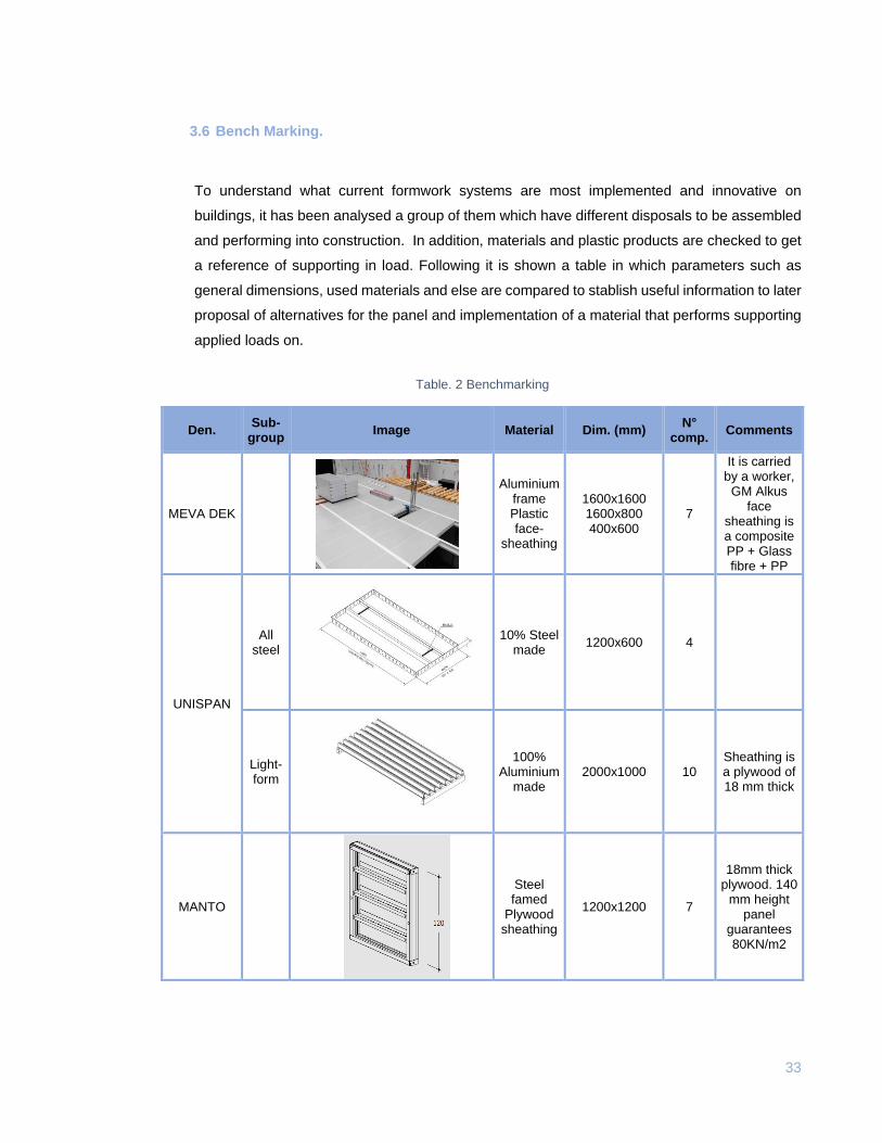
3.6 Bench Marking.
To understand what current formwork systems are most implemented and innovative on
buildings, it has been analysed a group of them which have different disposals to be assembled
and performing into construction. In addition, materials and plastic products are checked to get
a reference of supporting in load. Following it is shown a table in which parameters such as
general dimensions, used materials and else are compared to stablish useful information to later
proposal of alternatives for the panel and implementation of a material that performs supporting
applied loads on.
Table. 2 Benchmarking
Den. Sub-
group Image Material Dim. (mm)
N° comp.
Comments
MEVA DEK
Aluminium frame Plastic face-
sheathing
1600x1600 1600x800 400x600
7
It is carried by a worker, GM Alkus
face sheathing is a composite PP + Glass fibre + PP
UNISPAN
All steel
10% Steel made
1200x600 4
Light-form
100% Aluminium
made 2000x1000 10
Sheathing is a plywood of 18 mm thick
MANTO
Steel famed
Plywood sheathing
1200x1200 7
18mm thick plywood. 140
mm height panel
guarantees 80KN/m2
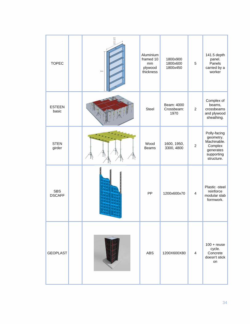
34
TOPEC
Aluminium framed 10
mm plywood thickness
1800x900 1800x600 1800x450
5
141.5 depth panel. Panels
carried by a worker
ESTEEN basic
Steel Beam: 4000 Crossbeam:
1970 2
Complex of beams,
crossbeams and plywood sheathing.
STEN girder
Wood Beams
1600, 1950, 3300, 4800
2
Polly-facing geometry.
Machinable. Complex generates supporting structure.
SBS DSCAFF
PP 1200x600x70 4
Plastic -steel reinforce
modular slab formwork.
GEOPLAST
ABS 1200X600X80 4
100 + reuse cycle.
Concrete doesn't stick
on
35
(Author)
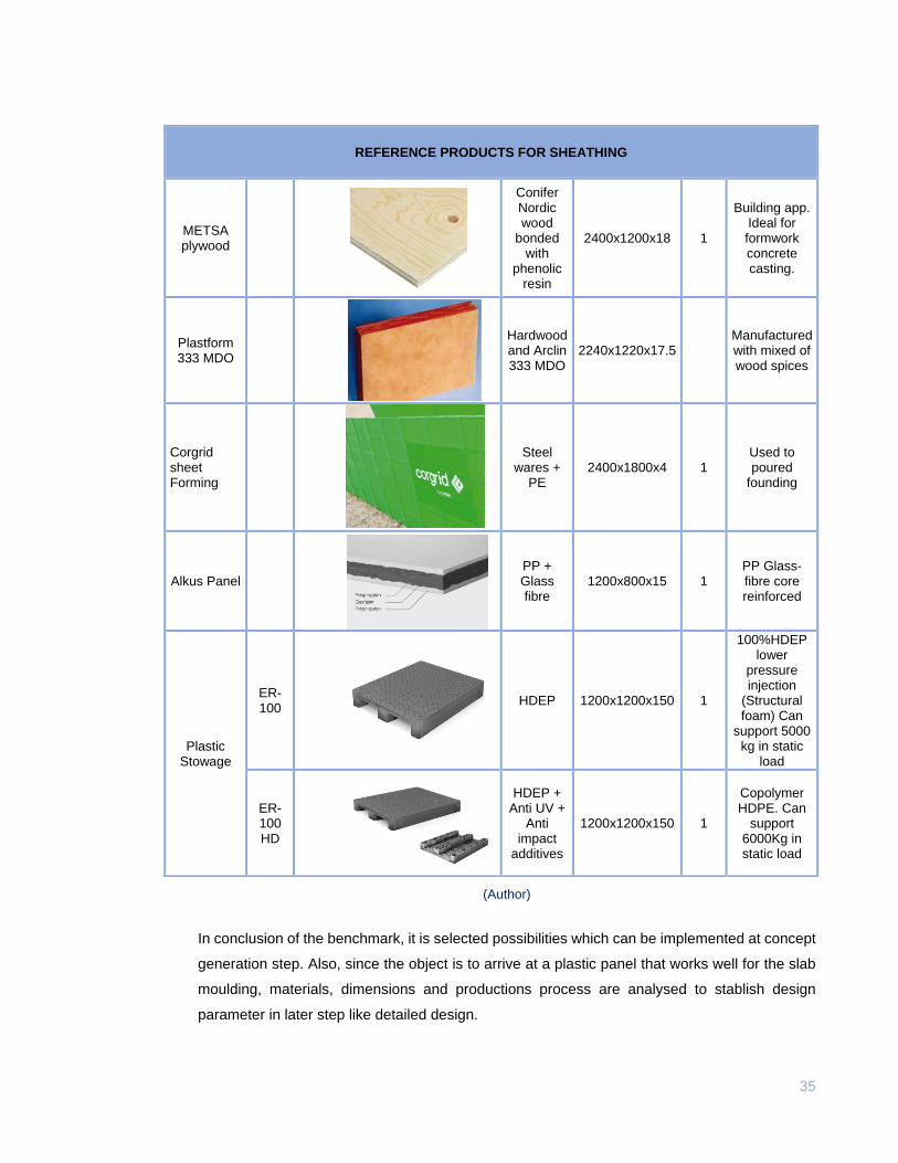
In conclusion of the benchmark, it is selected possibilities which can be implemented at concept
generation step. Also, since the object is to arrive at a plastic panel that works well for the slab
moulding, materials, dimensions and productions process are analysed to stablish design
parameter in later step like detailed design.
REFERENCE PRODUCTS FOR SHEATHING
METSA plywood
Conifer Nordic wood
bonded with
phenolic resin
2400x1200x18 1
Building app. Ideal for formwork concrete casting.
Plastform 333 MDO
Hardwood and Arclin 333 MDO
2240x1220x17.5 Manufactured with mixed of wood spices
Corgrid sheet Forming
Steel wares +
PE 2400x1800x4 1
Used to poured
founding
Alkus Panel
PP + Glass fibre
1200x800x15 1 PP Glass-fibre core reinforced
Plastic Stowage
ER-100
HDEP 1200x1200x150 1
100%HDEP lower
pressure injection
(Structural foam) Can
support 5000 kg in static
load
ER-100 HD
HDEP + Anti UV +
Anti impact
additives
1200x1200x150 1
Copolymer HDPE. Can
support 6000Kg in static load
36
Materials.
The most common material presented into benchmark is metallic one. Thanks to the high
performance because mechanical properties, it is fulfilling resistance and deformation at loading.
Plywood is the second material in the list, it is combined with metallic frames to generate panels,
it also has good resistance to deformation. However, since those materials are susceptible to
environmental agents, it is obligatory to add anticorrosion agents to care them.
Polymers are appearing in three of the options, in the materials reference there is a fibre produce
of polymer that is used in casting for foundations. Products such as Geoplast panel are 100%
polymer production, in contrast SBS panel is needing an embed steel reinforcement. It is present
in the MEVA DEK panel a composite which is working as sheathing component of the same.
Reference products for stowage are also 100% polymer and are supporting high loads during
long times because are used for storing.
So, a material’s resume to evaluate later to the product proposal is: High Density Polyethylene
(HDPE), Polyethylene (PE), Polypropylene (PP), Glass fibre and composites as in the Alkus
Panel is disposed PP plus Glass fibre. As those materials are currently implemented on formwork
products, it is done the material selection process once creation step has been done.
Dimensions
It is being analysed common dimensions presented on actual products to measure the proposed
product. It is important to notice that as buildings in Colombia are denotated in square meters,
constructors prefer to make panels which fulfil generic sizes where modules reach almost 1 m2.
So, according with it and expressed suggestions by workers, a synthesis is doing to arrive to
desire dimensions.
Larger panels oscillate between 1.8 * 1.8 m2 and 1.2 * 0.6 m2, as in the table 1 it is noticed.
There are elements like lumber which are measured in m, generally are form 3 to 6m.
Production process
Knowing that the project’s goal is to propose a plastic panel, it is deduced from the benchmarking
and background that injection and extrusion process have been used to produce panels.
However, it is well noticed that in Colombia it is used extrusion of plastic material to fabricate
different products made of. So, in consequence, it would be the best option to extrude a plastic
for this aim.
37
3.7 Design Parameters
Before to proceed with concepts generation and design alternatives for the product proposal,
design parameters are stablished to arrive at well approximation of panel ideas. Following, it is
described and shown product’s requirements.
3.7.1 Dimensions establishment.
As in benchmarking conclusions were described, dimensions are also referring to covered area
in which is going to be cast concrete. It means, building managers are in change to quantify the
number of square meters the need to use on the slab forming. So, to in that case, the panel
should be measured whit an area closer to 1 m2 that is facilitating the work out quantification.
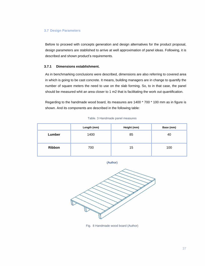
Regarding to the handmade wood board, its measures are 1400 * 700 * 100 mm as in figure is
shown. And its components are described in the following table:
Table. 3 Handmade panel measures
Length (mm) Height (mm) Base (mm)
Lumber 1400 85 40
Ribbon 700 15 100
(Author)
Fig. 8 Handmade wood board (Author)
38
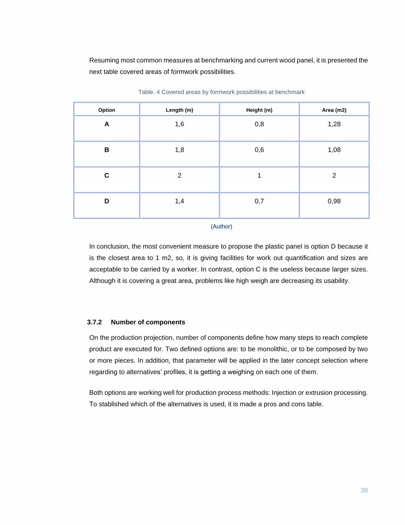
Resuming most common measures at benchmarking and current wood panel, it is presented the
next table covered areas of formwork possibilities.
Table. 4 Covered areas by formwork possibilities at benchmark
Option Length (m) Height (m) Area (m2)
A 1,6 0,8 1,28
B 1,8 0,6 1,08
C 2 1 2
D 1,4 0,7 0,98
(Author)
In conclusion, the most convenient measure to propose the plastic panel is option D because it
is the closest area to 1 m2, so, it is giving facilities for work out quantification and sizes are
acceptable to be carried by a worker. In contrast, option C is the useless because larger sizes.
Although it is covering a great area, problems like high weigh are decreasing its usability.
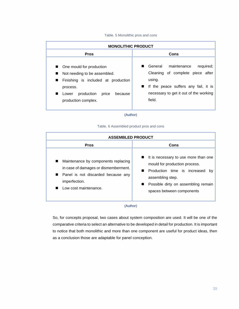
3.7.2 Number of components
On the production projection, number of components define how many steps to reach complete
product are executed for. Two defined options are: to be monolithic, or to be composed by two
or more pieces. In addition, that parameter will be applied in the later concept selection where
regarding to alternatives’ profiles, it is getting a weighing on each one of them.
Both options are working well for production process methods: Injection or extrusion processing.
To stablished which of the alternatives is used, it is made a pros and cons table.
39
Table. 5 Monolithic pros and cons
MONOLITHIC PRODUCT
Length (m) Pros Cons
One mould for production
Not needing to be assembled.
Finishing is included at production
process.
Lower production price because
production complex.
General maintenance required;
Cleaning of complete piece after
using.
If the peace suffers any fail, it is
necessary to get it out of the working
field.
(Author)
Table. 6 Assembled product pros and cons
ASSEMBLED PRODUCT
Length (m) Pros Cons
Maintenance by components replacing
in case of damages or dismemberment.
Panel is not discarded because any
imperfection.
Low cost maintenance.
It is necessary to use more than one
mould for production process.
Production time is increased by
assembling step.
Possible dirty on assembling remain
spaces between components
(Author)
So, for concepts proposal, two cases about system composition are used. It will be one of the
comparative criteria to select an alternative to be developed in detail for production. It is important
to notice that both monolithic and more than one component are useful for product ideas, then
as a conclusion those are adaptable for panel conception.
40
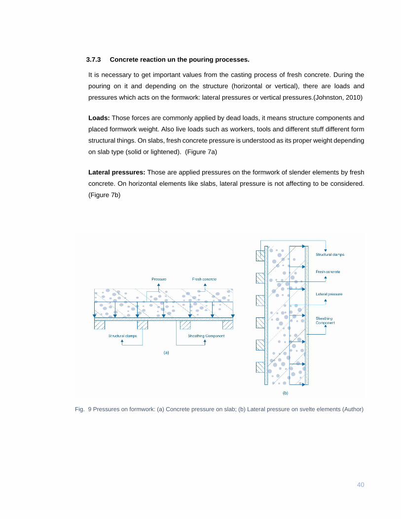
3.7.3 Concrete reaction un the pouring processes.
It is necessary to get important values from the casting process of fresh concrete. During the
pouring on it and depending on the structure (horizontal or vertical), there are loads and
pressures which acts on the formwork: lateral pressures or vertical pressures.(Johnston, 2010)
Loads: Those forces are commonly applied by dead loads, it means structure components and
placed formwork weight. Also live loads such as workers, tools and different stuff different form
structural things. On slabs, fresh concrete pressure is understood as its proper weight depending
on slab type (solid or lightened). (Figure 7a)
Lateral pressures: Those are applied pressures on the formwork of slender elements by fresh
concrete. On horizontal elements like slabs, lateral pressure is not affecting to be considered.
(Figure 7b)
Fig. 9 Pressures on formwork: (a) Concrete pressure on slab; (b) Lateral pressure on svelte elements (Author)
41
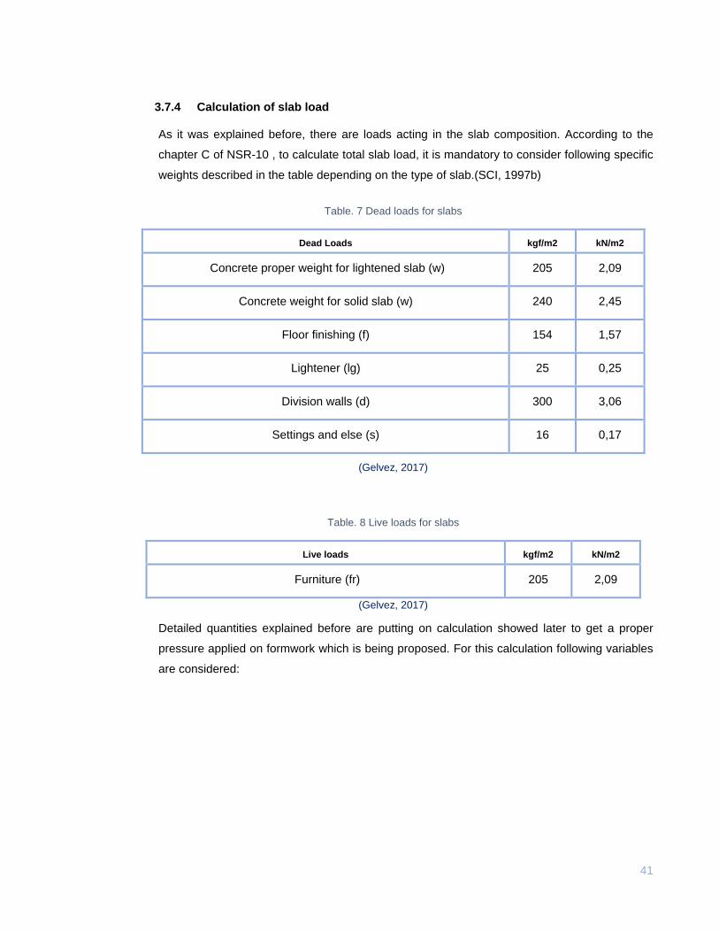
3.7.4 Calculation of slab load
As it was explained before, there are loads acting in the slab composition. According to the
chapter C of NSR-10 , to calculate total slab load, it is mandatory to consider following specific
weights described in the table depending on the type of slab.(SCI, 1997b)
Table. 7 Dead loads for slabs
Dead Loads kgf/m2 kN/m2
Concrete proper weight for lightened slab (w) 205 2,09
Concrete weight for solid slab (w) 240 2,45
Floor finishing (f) 154 1,57
Lightener (lg) 25 0,25
Division walls (d) 300 3,06
Settings and else (s) 16 0,17
(Gelvez, 2017)
Table. 8 Live loads for slabs
Live loads kgf/m2 kN/m2
Furniture (fr) 205 2,09
(Gelvez, 2017)
Detailed quantities explained before are putting on calculation showed later to get a proper
pressure applied on formwork which is being proposed. For this calculation following variables
are considered:
42
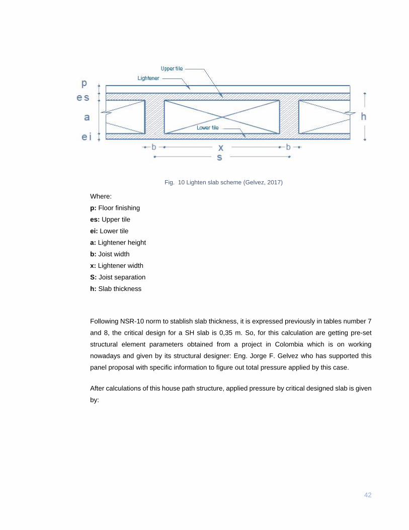
Fig. 10 Lighten slab scheme (Gelvez, 2017)
Where:
p: Floor finishing
es: Upper tile
ei: Lower tile
a: Lightener height
b: Joist width
x: Lightener width
S: Joist separation
h: Slab thickness
Following NSR-10 norm to stablish slab thickness, it is expressed previously in tables number 7
and 8, the critical design for a SH slab is 0,35 m. So, for this calculation are getting pre-set
structural element parameters obtained from a project in Colombia which is on working
nowadays and given by its structural designer: Eng. Jorge F. Gelvez who has supported this
panel proposal with specific information to figure out total pressure applied by this case.
After calculations of this house path structure, applied pressure by critical designed slab is given
by:
43
Dead loads (kgf/m2)
w: 205
f: 154
lg: 25
d: 300
s: 16
Live loads (kgf/m2)
fr: 180
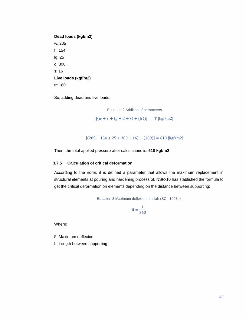
So, adding dead and live loads:
Equation 2 Addition of parameters
[(𝑤 + 𝑓 + 𝑙𝑔 + 𝑑 + 𝑠) + (fr))] = T [kgf/m2]
[(205 + 154 + 25 + 300 + 16) + (180)] = 610 [kgf/m2]
Then, the total applied pressure after calculations is: 610 kgf/m2
3.7.5 Calculation of critical deformation
According to the norm, it is defined a parameter that allows the maximum replacement in
structural elements at pouring and hardening process of. NSR-10 has stablished the formula to
get the critical deformation on elements depending on the distance between supporting:
Equation 3 Maximum deflexion on slab (SCI, 1997b)
𝜹 =𝑙
360
Where:
ẟ: Maximum deflexion
L: Length between supporting
44
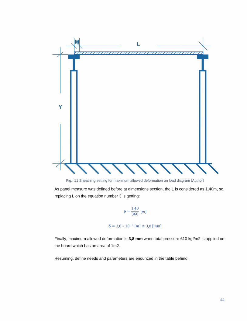
Fig. 11 Sheathing setting for maximum allowed deformation on load diagram (Author)
As panel measure was defined before at dimensions section, the L is considered as 1,40m, so,
replacing L on the equation number 3 is getting:
𝜹 =1,40
360 [𝑚]
𝜹 = 3,8 ∗ 10−3 [𝑚] ≅ 3,8 [𝑚𝑚]
Finally, maximum allowed deformation is 3,8 mm when total pressure 610 kgf/m2 is applied on
the board which has an area of 1m2.
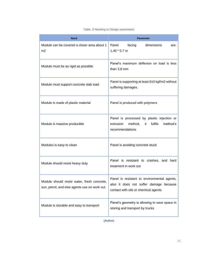
Resuming, define needs and parameters are enounced in the table behind:
45
Table. 9 Needing to Design parameters
Need Parameter
Module can be covered a closer area about 1
m2
Panel facing dimensions are:
1,40 * 0.7 m
Module must be as rigid as possible Panel’s maximum deflexion on load is less
than 3,8 mm
Module must support concrete slab load Panel is supporting at least 610 kgf/m2 without
suffering damages.
Module is made of plastic material Panel is produced with polymers
Module is massive producible
Panel is processed by plastic injection or
extrusion method, it fulfils method’s
recommendations
Modules is easy to clean Panel is avoiding concrete stuck
Module should resist heavy duty Panel is resistant to crashes, and hard
treatment in work out
Module should resist water, fresh concrete,
sun, petrol, and else agents use on work out.
Panel is resistant to environmental agents,
also it does not suffer damage because
contact with oils or chemical agents
Module is storable and easy to transport Panel’s geometry is allowing to save space in
storing and transport by trucks
(Author)
46
4. CONCEPT
4.1 Ideation process
Ideation step is applying to arrive at first concept possibilities for the panel. In the process, existing
articles for civil work out are analysed to extract profiles, shapes and supporting structures which are
constantly working on load.
Following, these are showed and explained current products and structures for buildings, in addition
actual wood and plastic panels profiles are analysed to generate primary ideas.
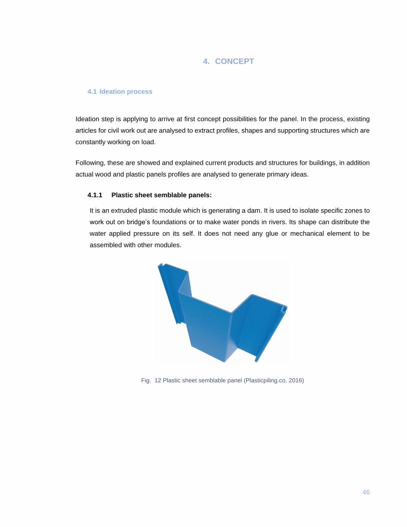
4.1.1 Plastic sheet semblable panels:
It is an extruded plastic module which is generating a dam. It is used to isolate specific zones to
work out on bridge’s foundations or to make water ponds in rivers. Its shape can distribute the
water applied pressure on its self. It does not need any glue or mechanical element to be
assembled with other modules.
Fig. 12 Plastic sheet semblable panel (Plasticpiling.co, 2016)
47
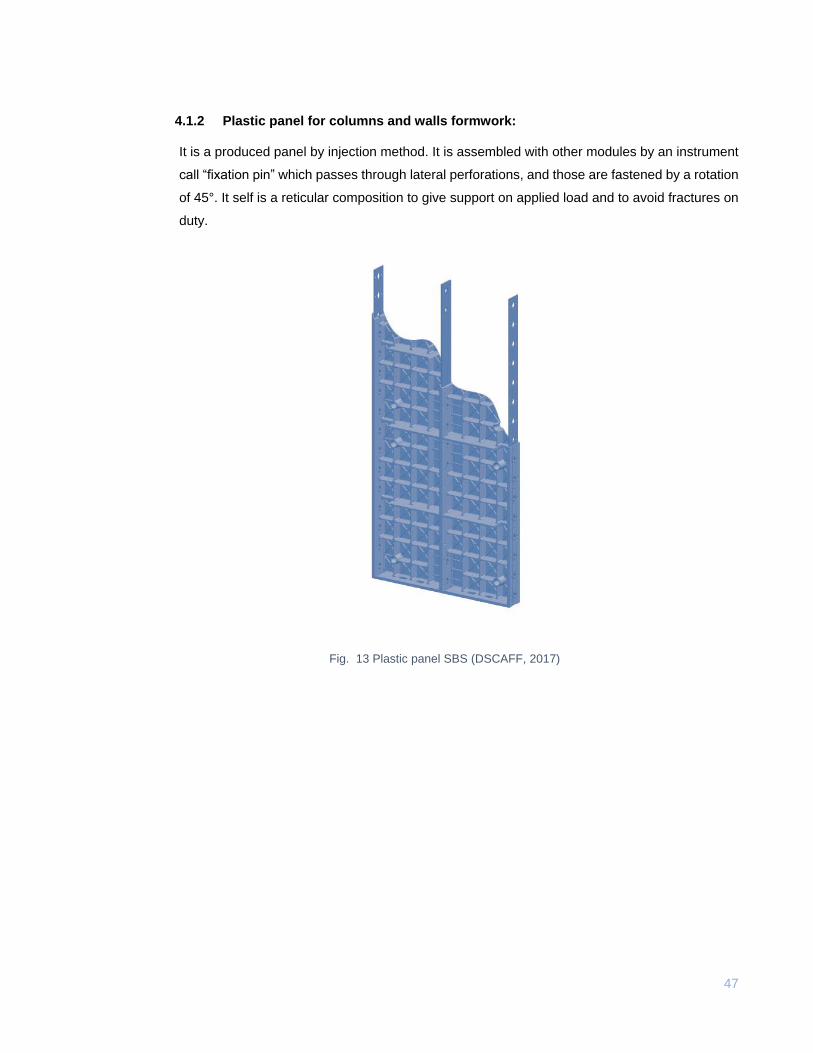
4.1.2 Plastic panel for columns and walls formwork:
It is a produced panel by injection method. It is assembled with other modules by an instrument
call “fixation pin” which passes through lateral perforations, and those are fastened by a rotation
of 45°. It self is a reticular composition to give support on applied load and to avoid fractures on
duty.
Fig. 13 Plastic panel SBS (DSCAFF, 2017)
48
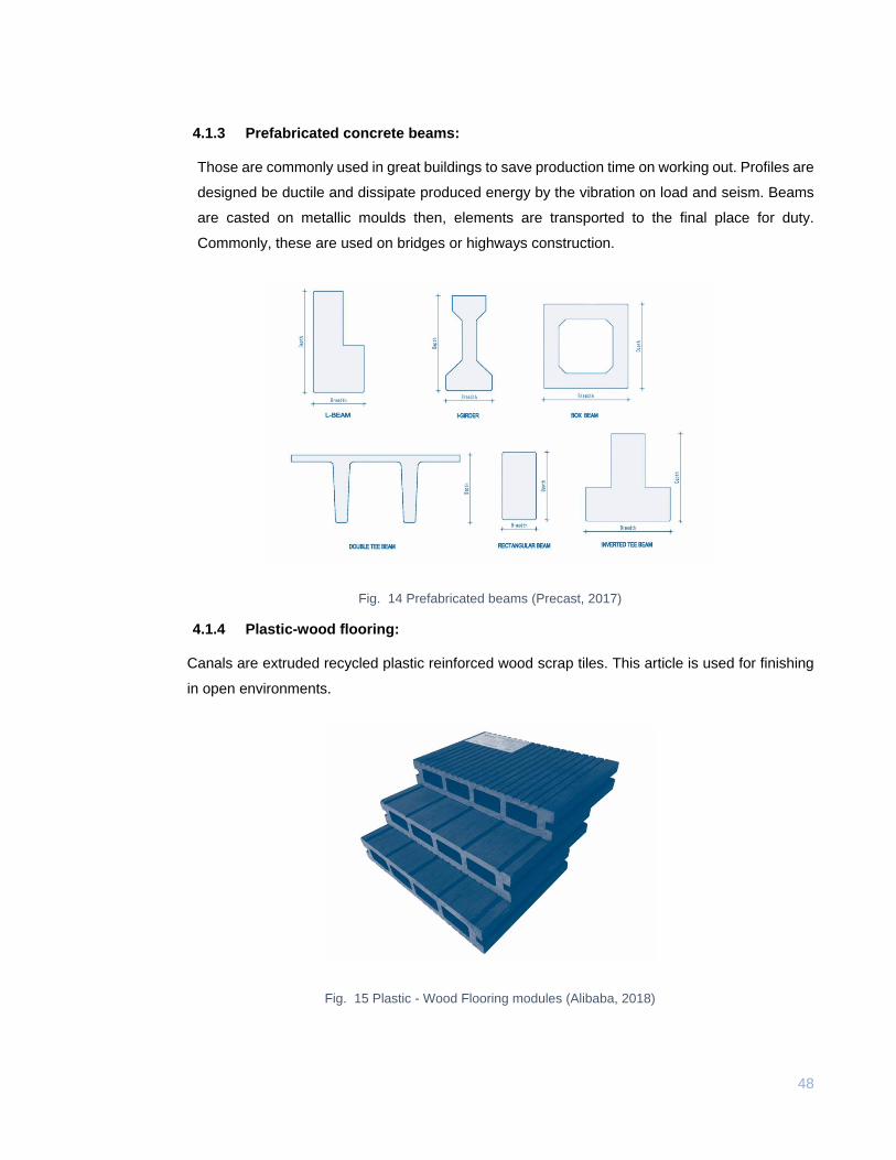
4.1.3 Prefabricated concrete beams:
Those are commonly used in great buildings to save production time on working out. Profiles are
designed be ductile and dissipate produced energy by the vibration on load and seism. Beams
are casted on metallic moulds then, elements are transported to the final place for duty.
Commonly, these are used on bridges or highways construction.
Fig. 14 Prefabricated beams (Precast, 2017)
4.1.4 Plastic-wood flooring:
Canals are extruded recycled plastic reinforced wood scrap tiles. This article is used for finishing
in open environments.
Fig. 15 Plastic - Wood Flooring modules (Alibaba, 2018)
49
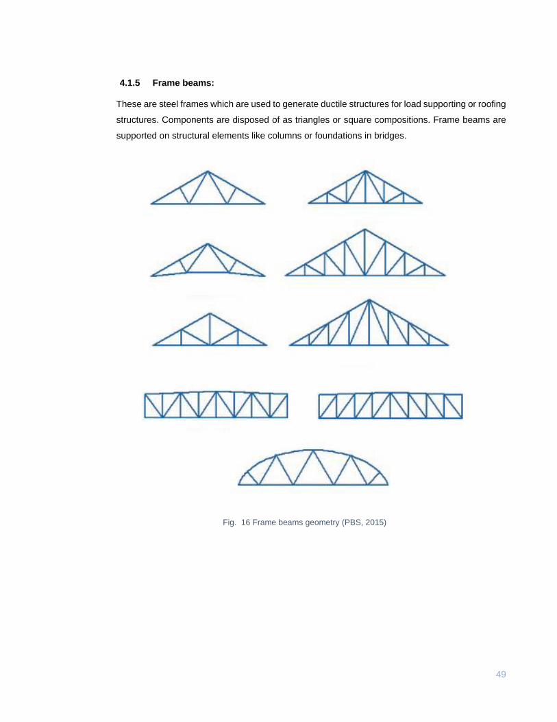
4.1.5 Frame beams:
These are steel frames which are used to generate ductile structures for load supporting or roofing
structures. Components are disposed of as triangles or square compositions. Frame beams are
supported on structural elements like columns or foundations in bridges.
Fig. 16 Frame beams geometry (PBS, 2015)
50
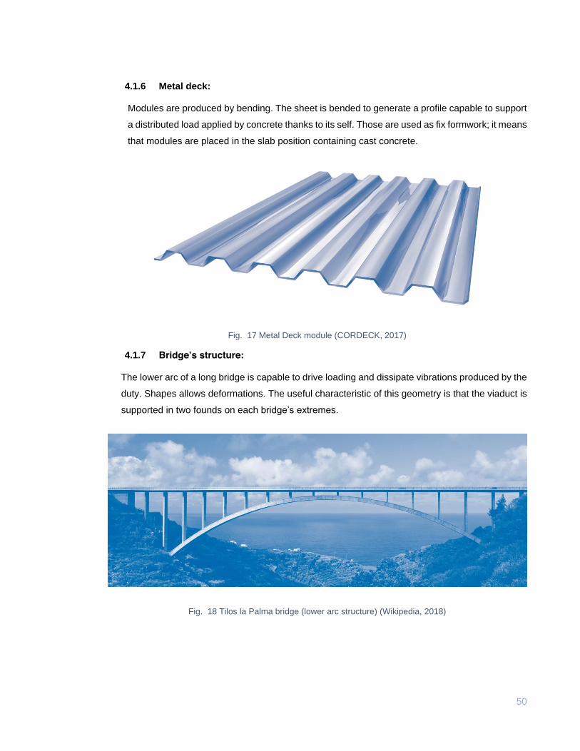
4.1.6 Metal deck:
Modules are produced by bending. The sheet is bended to generate a profile capable to support
a distributed load applied by concrete thanks to its self. Those are used as fix formwork; it means
that modules are placed in the slab position containing cast concrete.
Fig. 17 Metal Deck module (CORDECK, 2017)
4.1.7 Bridge’s structure:
The lower arc of a long bridge is capable to drive loading and dissipate vibrations produced by the
duty. Shapes allows deformations. The useful characteristic of this geometry is that the viaduct is
supported in two founds on each bridge’s extremes.
Fig. 18 Tilos la Palma bridge (lower arc structure) (Wikipedia, 2018)
51
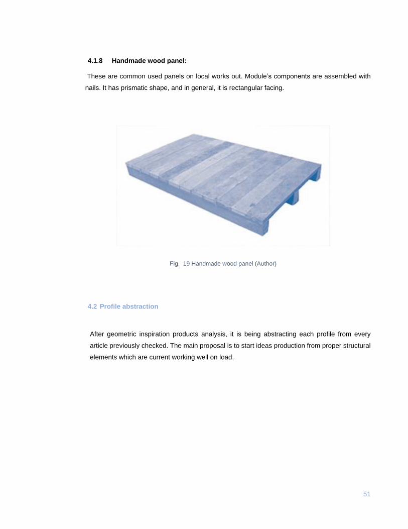
4.1.8 Handmade wood panel:
These are common used panels on local works out. Module’s components are assembled with
nails. It has prismatic shape, and in general, it is rectangular facing.
Fig. 19 Handmade wood panel (Author)
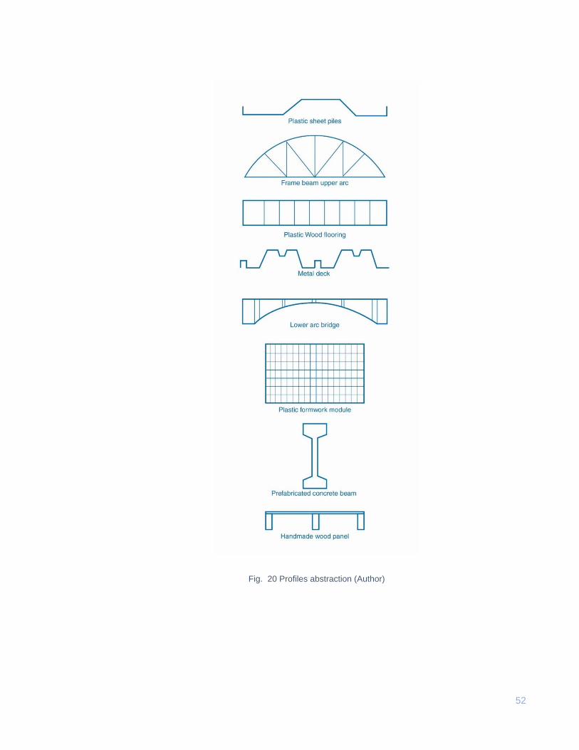
4.2 Profile abstraction
After geometric inspiration products analysis, it is being abstracting each profile from every
article previously checked. The main proposal is to start ideas production from proper structural
elements which are current working well on load.
52
Fig. 20 Profiles abstraction (Author)
53
4.3 Design alternatives
Following the process, first sketches have been produced to generate alternatives for the panel;
each idea is stablished to fulfil design parameters and needs. After merging primitive profiles
explained before, there are presented four proposals for ideation to be later evaluated.
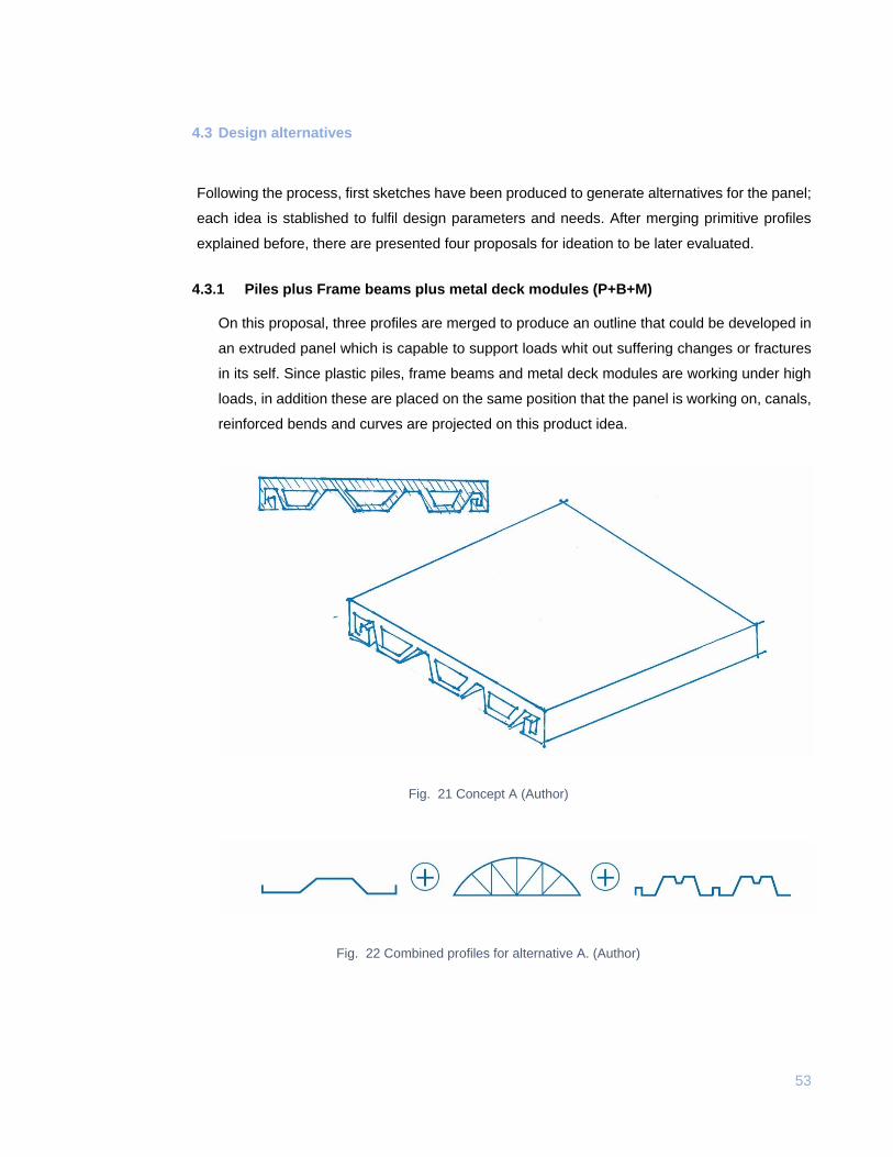
4.3.1 Piles plus Frame beams plus metal deck modules (P+B+M)
On this proposal, three profiles are merged to produce an outline that could be developed in
an extruded panel which is capable to support loads whit out suffering changes or fractures
in its self. Since plastic piles, frame beams and metal deck modules are working under high
loads, in addition these are placed on the same position that the panel is working on, canals,
reinforced bends and curves are projected on this product idea.
Fig. 21 Concept A (Author)
Fig. 22 Combined profiles for alternative A. (Author)
54
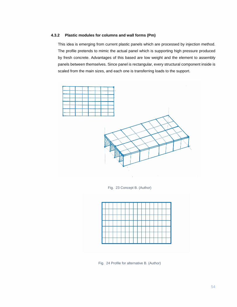
4.3.2 Plastic modules for columns and wall forms (Pm)
This idea is emerging from current plastic panels which are processed by injection method.
The profile pretends to mimic the actual panel which is supporting high pressure produced
by fresh concrete. Advantages of this based are low weight and the element to assembly
panels between themselves. Since panel is rectangular, every structural component inside is
scaled from the main sizes, and each one is transferring loads to the support.
Fig. 23 Concept B. (Author)
Fig. 24 Profile for alternative B. (Author)
55
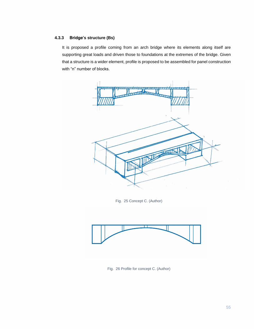
4.3.3 Bridge’s structure (Bs)
It is proposed a profile coming from an arch bridge where its elements along itself are
supporting great loads and driven those to foundations at the extremes of the bridge. Given
that a structure is a wider element, profile is proposed to be assembled for panel construction
with “n” number of blocks.
Fig. 25 Concept C. (Author)
Fig. 26 Profile for concept C. (Author)
56
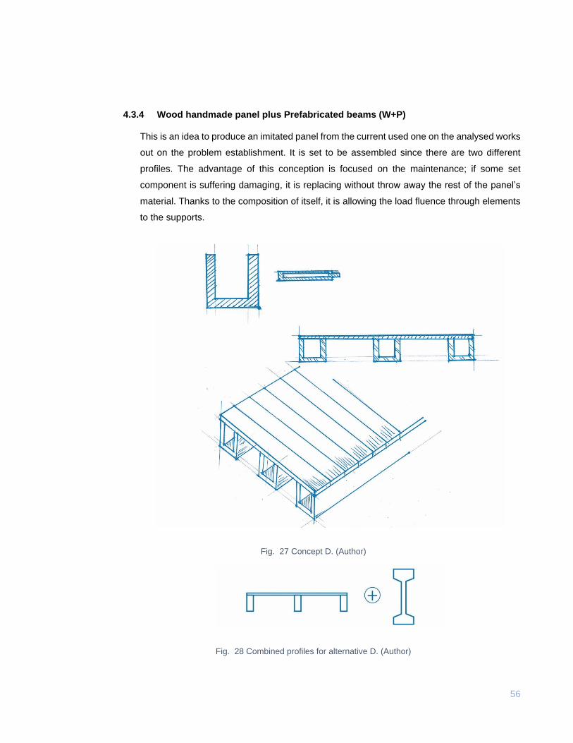
4.3.4 Wood handmade panel plus Prefabricated beams (W+P)
This is an idea to produce an imitated panel from the current used one on the analysed works
out on the problem establishment. It is set to be assembled since there are two different
profiles. The advantage of this conception is focused on the maintenance; if some set
component is suffering damaging, it is replacing without throw away the rest of the panel’s
material. Thanks to the composition of itself, it is allowing the load fluence through elements
to the supports.
Fig. 27 Concept D. (Author)
Fig. 28 Combined profiles for alternative D. (Author)
57
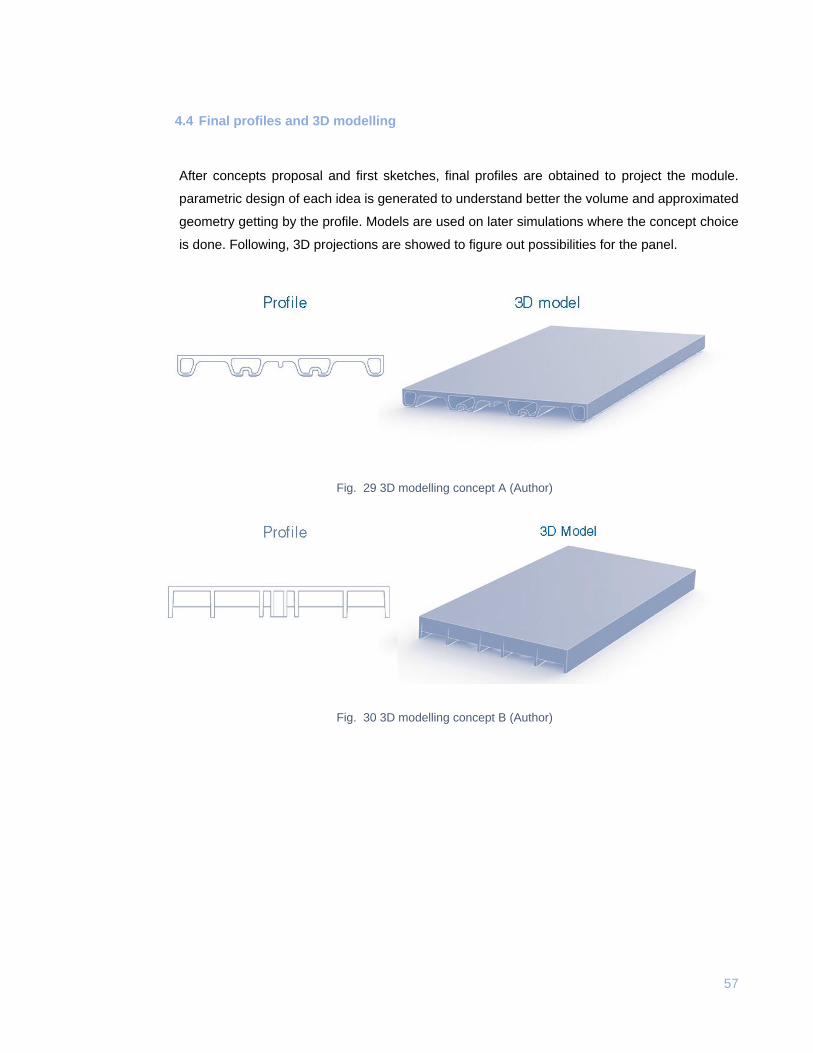
4.4 Final profiles and 3D modelling
After concepts proposal and first sketches, final profiles are obtained to project the module.
parametric design of each idea is generated to understand better the volume and approximated
geometry getting by the profile. Models are used on later simulations where the concept choice
is done. Following, 3D projections are showed to figure out possibilities for the panel.
Fig. 29 3D modelling concept A (Author)
Fig. 30 3D modelling concept B (Author)
58
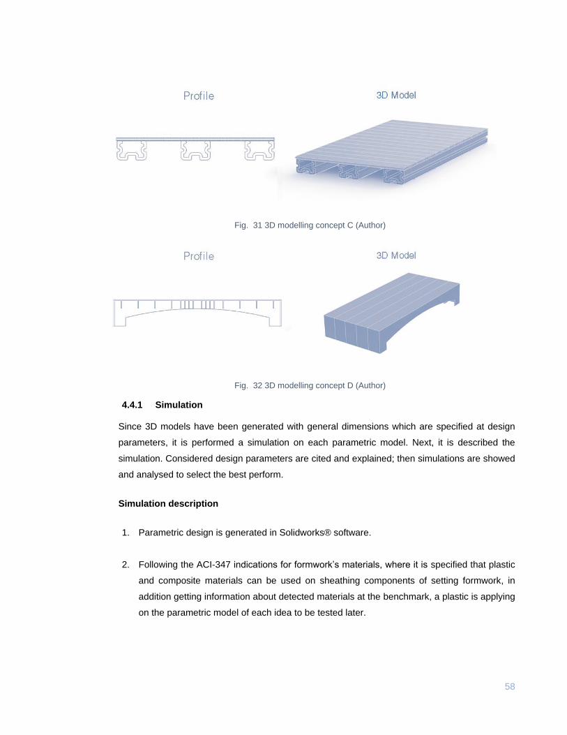
Fig. 31 3D modelling concept C (Author)
Fig. 32 3D modelling concept D (Author)
4.4.1 Simulation
Since 3D models have been generated with general dimensions which are specified at design
parameters, it is performed a simulation on each parametric model. Next, it is described the
simulation. Considered design parameters are cited and explained; then simulations are showed
and analysed to select the best perform.
Simulation description
1. Parametric design is generated in Solidworks® software.
2. Following the ACI-347 indications for formwork’s materials, where it is specified that plastic
and composite materials can be used on sheathing components of setting formwork, in
addition getting information about detected materials at the benchmark, a plastic is applying
on the parametric model of each idea to be tested later.
59
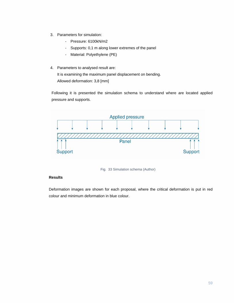
3. Parameters for simulation:
- Pressure: 6100kN/m2
- Supports: 0,1 m along lower extremes of the panel
- Material: Polyethylene (PE)
4. Parameters to analysed result are:
It is examining the maximum panel displacement on bending.
Allowed deformation: 3,8 [mm]
Following it is presented the simulation schema to understand where are located applied
pressure and supports.
Fig. 33 Simulation schema (Author)
Results
Deformation images are shown for each proposal, where the critical deformation is put in red
colour and minimum deformation in blue colour.
60
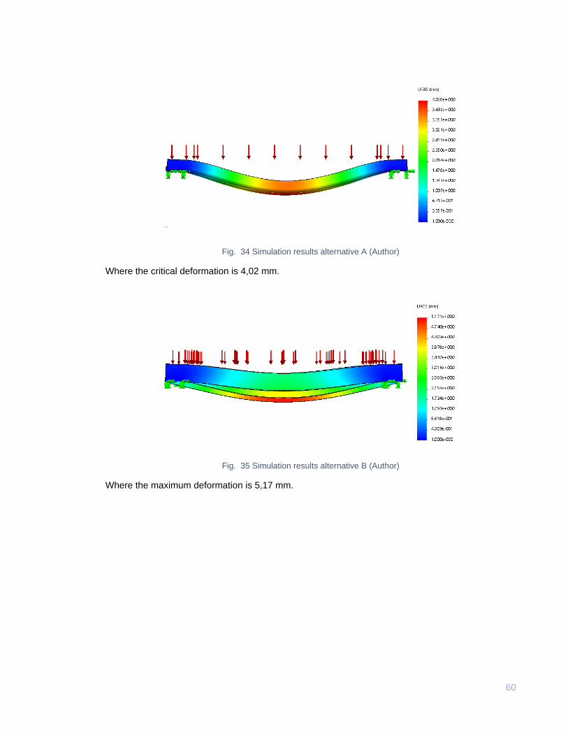
Fig. 34 Simulation results alternative A (Author)
Where the critical deformation is 4,02 mm.
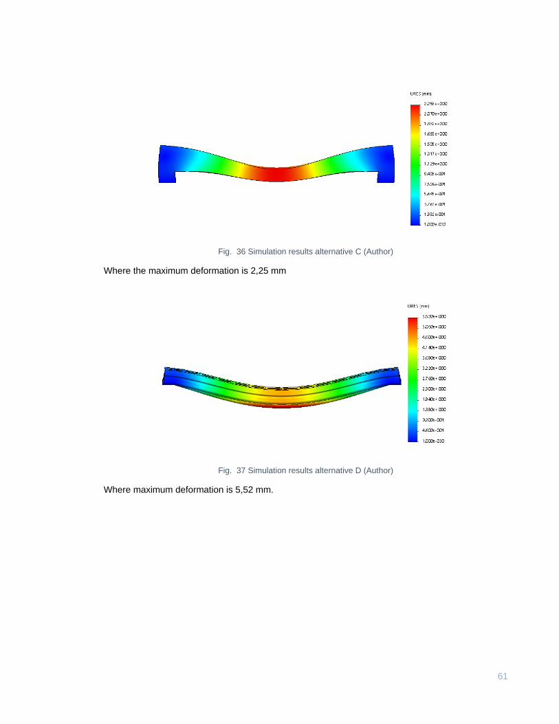
Fig. 35 Simulation results alternative B (Author)
Where the maximum deformation is 5,17 mm.
61
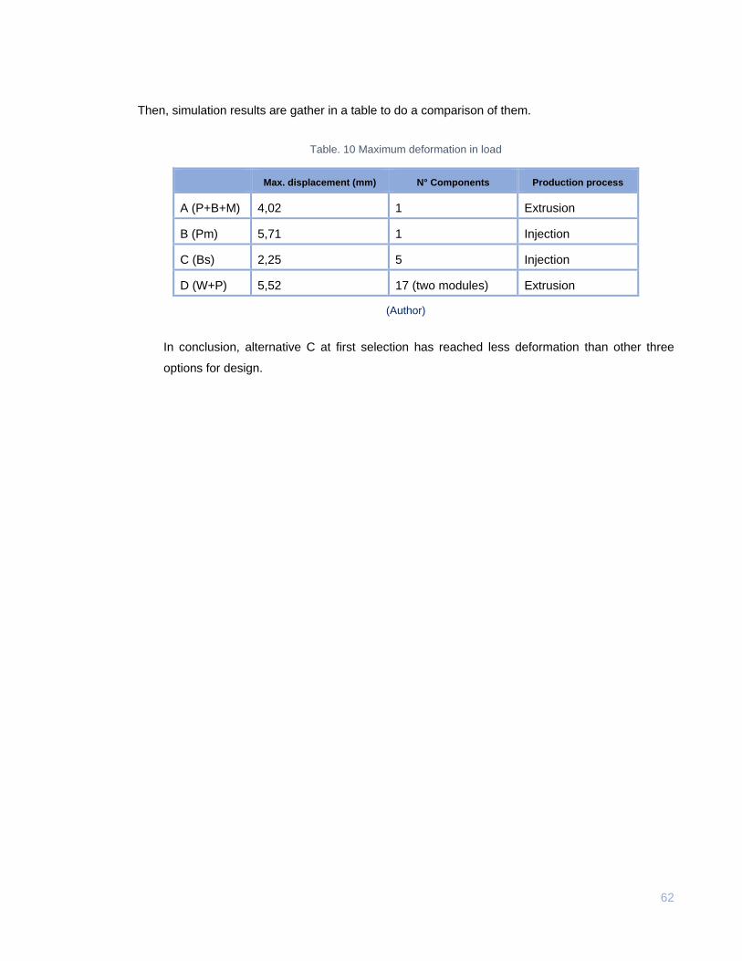
Fig. 36 Simulation results alternative C (Author)
Where the maximum deformation is 2,25 mm
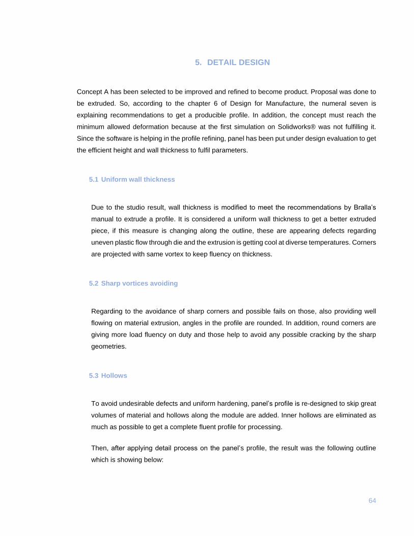
Fig. 37 Simulation results alternative D (Author)
Where maximum deformation is 5,52 mm.
62
Then, simulation results are gather in a table to do a comparison of them.
Table. 10 Maximum deformation in load
Max. displacement (mm) N° Components Production process
A (P+B+M) 4,02 1 Extrusion
B (Pm) 5,71 1 Injection
C (Bs) 2,25 5 Injection
D (W+P) 5,52 17 (two modules) Extrusion
(Author)
In conclusion, alternative C at first selection has reached less deformation than other three
options for design.

63
4.5 Concept selection
After the simulation analysis where deformation quantities have been determined, it is done the
concept selection through a matrix where parameters are evaluated and graded according to its
performance on each concept.
Grades: To select a concept, it is established a scale to give grades for each proposal, where:
- 1: Fails
- 3: Fairly fulfil
- 5: Fulfil
Table. 11 Concept selection matrix
CONC. A B C D
PA
RA
ME
TE
R
Panel facing dimensions are: 1,40 * 0.7 m 5 5 1 5
Panel’s maximum deflexion on load is less than 3,8 mm 1 1 5 1
Panel is supporting at least 610 kgf/m2 without suffering damages. 5 5 3 3
Panel is produced with polymers or composites 5 5 5 5
Panel is processed by plastic injection or extrusion method, it fulfils method’s recommendations
3 1 3 5
Panel is avoiding concrete stuck 5 5 3 3
Panel is resistant to crashes, and hard treatment in work out 5 3 3 5
Panel is resistant to environmental agents, also it does not suffer damage because contact with oils or chemical agents
5 5 5 5
Panel’s geometry is allowing to save space in storing and transport by trucks 3 3 3 3
Grade 37 33 31 35
(Author)
In conclusion, after the matrix selection concept A has been fulfilled better than others with
design parameters. Then, proposal A is being improved in design of details to later production
by extrusion process.
64
5. DETAIL DESIGN
Concept A has been selected to be improved and refined to become product. Proposal was done to
be extruded. So, according to the chapter 6 of Design for Manufacture, the numeral seven is
explaining recommendations to get a producible profile. In addition, the concept must reach the
minimum allowed deformation because at the first simulation on Solidworks® was not fulfilling it.
Since the software is helping in the profile refining, panel has been put under design evaluation to get
the efficient height and wall thickness to fulfil parameters.
5.1 Uniform wall thickness
Due to the studio result, wall thickness is modified to meet the recommendations by Bralla’s
manual to extrude a profile. It is considered a uniform wall thickness to get a better extruded
piece, if this measure is changing along the outline, these are appearing defects regarding
uneven plastic flow through die and the extrusion is getting cool at diverse temperatures. Corners
are projected with same vortex to keep fluency on thickness.
5.2 Sharp vortices avoiding
Regarding to the avoidance of sharp corners and possible fails on those, also providing well
flowing on material extrusion, angles in the profile are rounded. In addition, round corners are
giving more load fluency on duty and those help to avoid any possible cracking by the sharp
geometries.
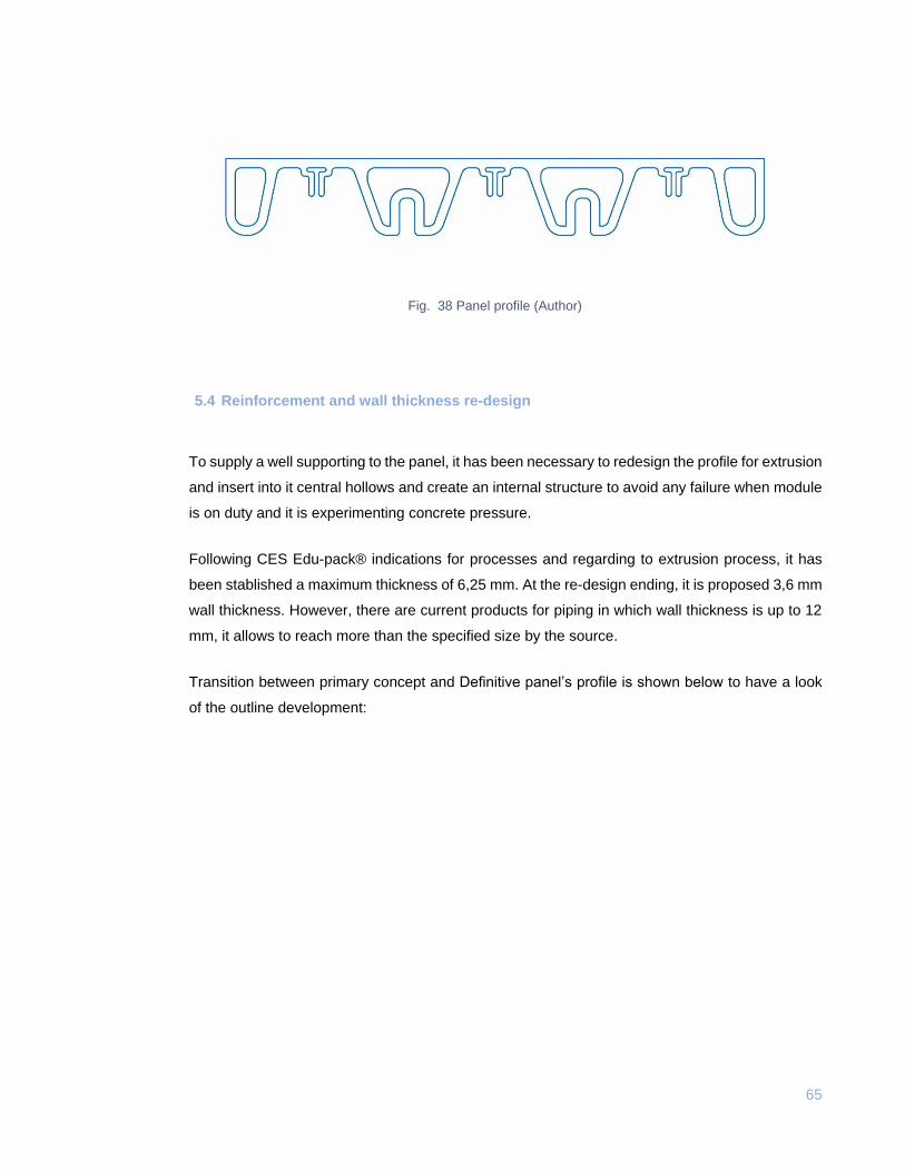
5.3 Hollows
To avoid undesirable defects and uniform hardening, panel’s profile is re-designed to skip great
volumes of material and hollows along the module are added. Inner hollows are eliminated as
much as possible to get a complete fluent profile for processing.
Then, after applying detail process on the panel’s profile, the result was the following outline
which is showing below:
65
Fig. 38 Panel profile (Author)
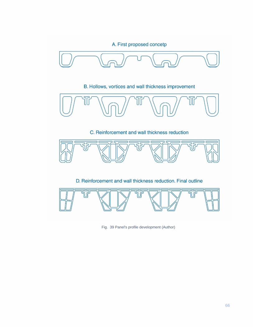
5.4 Reinforcement and wall thickness re-design
To supply a well supporting to the panel, it has been necessary to redesign the profile for extrusion
and insert into it central hollows and create an internal structure to avoid any failure when module
is on duty and it is experimenting concrete pressure.
Following CES Edu-pack® indications for processes and regarding to extrusion process, it has
been stablished a maximum thickness of 6,25 mm. At the re-design ending, it is proposed 3,6 mm
wall thickness. However, there are current products for piping in which wall thickness is up to 12
mm, it allows to reach more than the specified size by the source.
Transition between primary concept and Definitive panel’s profile is shown below to have a look
of the outline development:
66
Fig. 39 Panel's profile development (Author)
67
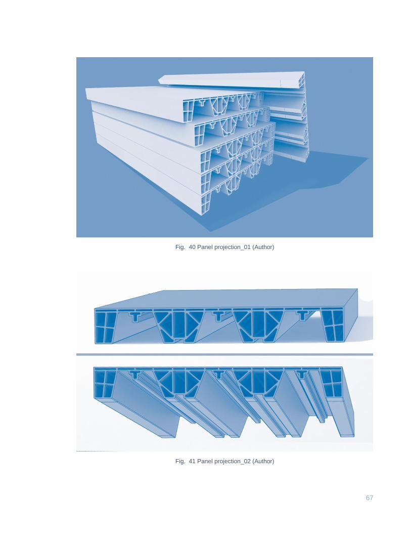
Fig. 40 Panel projection_01 (Author)
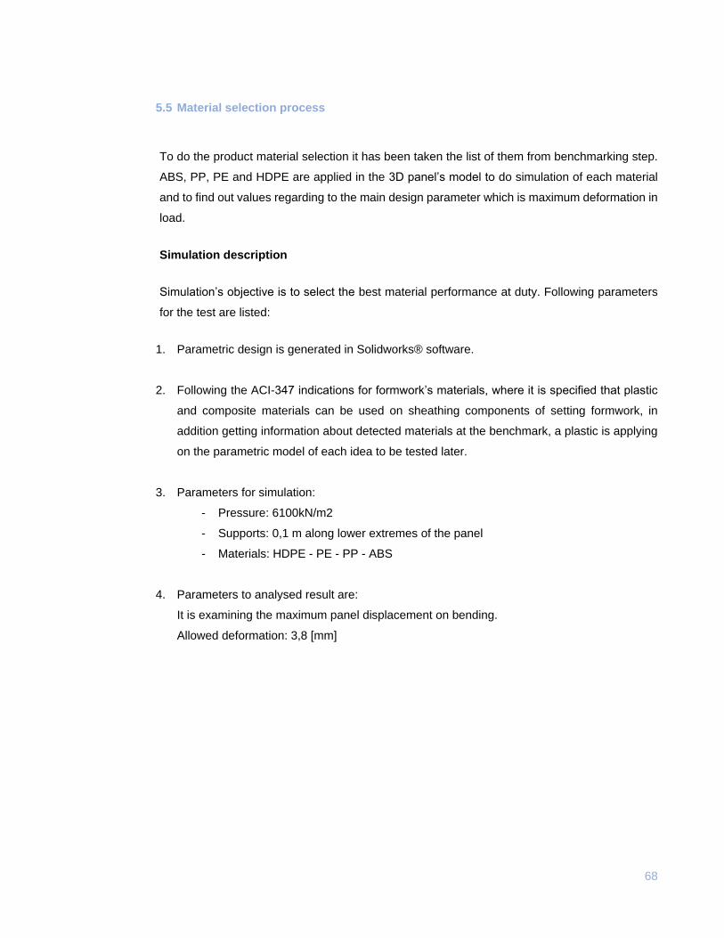
Fig. 41 Panel projection_02 (Author)
68
5.5 Material selection process
To do the product material selection it has been taken the list of them from benchmarking step.
ABS, PP, PE and HDPE are applied in the 3D panel’s model to do simulation of each material
and to find out values regarding to the main design parameter which is maximum deformation in
load.
Simulation description
Simulation’s objective is to select the best material performance at duty. Following parameters
for the test are listed:
1. Parametric design is generated in Solidworks® software.
2. Following the ACI-347 indications for formwork’s materials, where it is specified that plastic
and composite materials can be used on sheathing components of setting formwork, in
addition getting information about detected materials at the benchmark, a plastic is applying
on the parametric model of each idea to be tested later.
3. Parameters for simulation:
- Pressure: 6100kN/m2
- Supports: 0,1 m along lower extremes of the panel
- Materials: HDPE - PE - PP - ABS
4. Parameters to analysed result are:
It is examining the maximum panel displacement on bending.
Allowed deformation: 3,8 [mm]
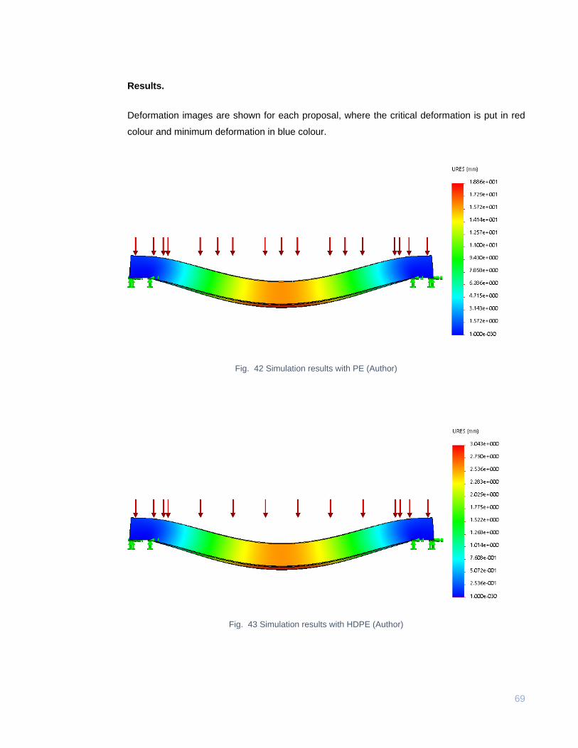
69
Results.
Deformation images are shown for each proposal, where the critical deformation is put in red
colour and minimum deformation in blue colour.
Fig. 42 Simulation results with PE (Author)
Fig. 43 Simulation results with HDPE (Author)
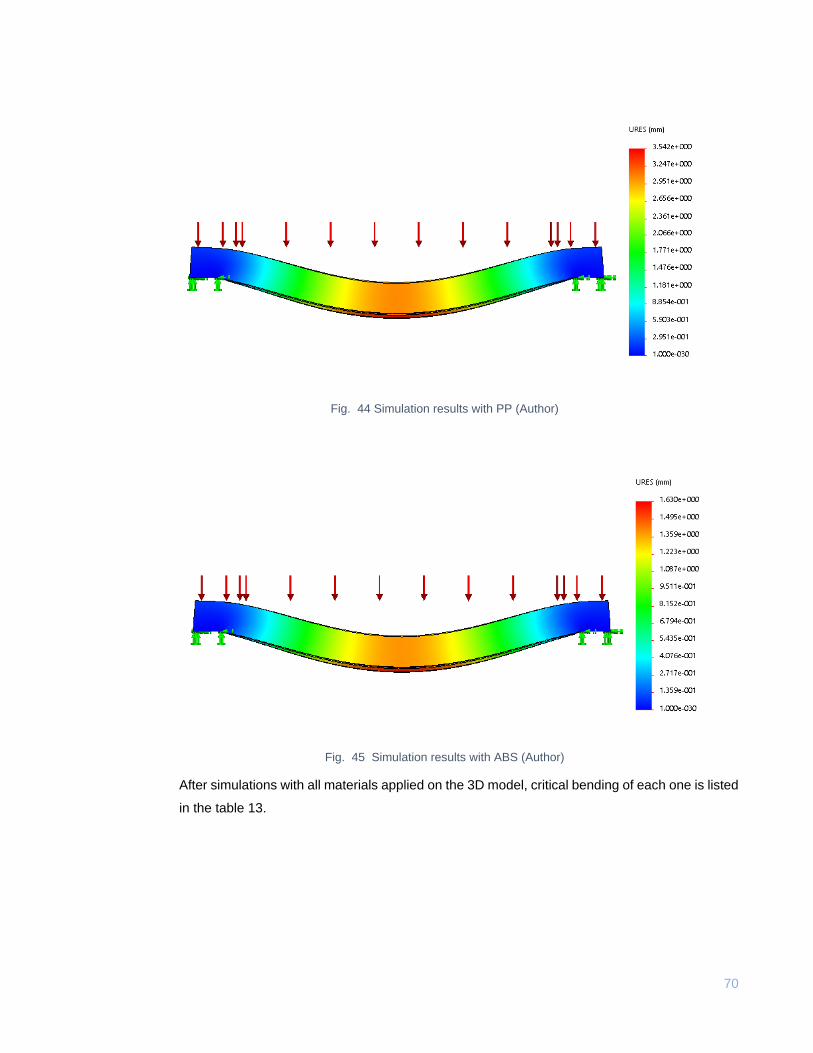
70
Fig. 44 Simulation results with PP (Author)
Fig. 45 Simulation results with ABS (Author)
After simulations with all materials applied on the 3D model, critical bending of each one is listed
in the table 13.
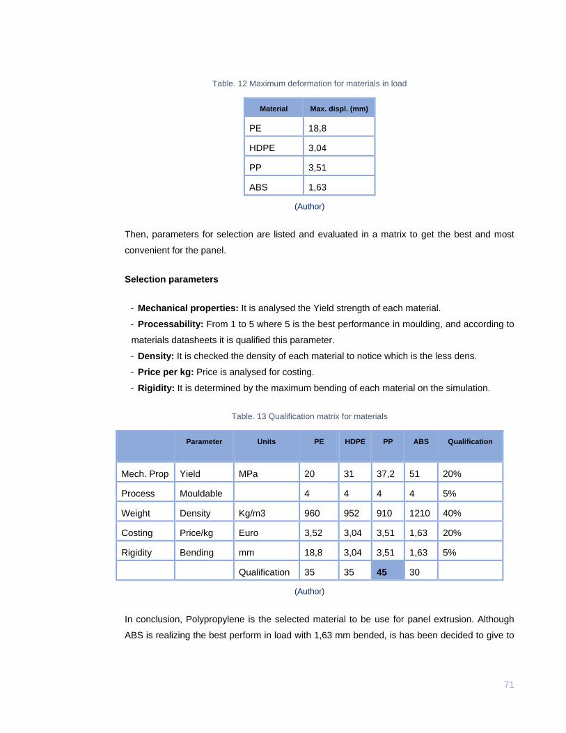
71
Table. 12 Maximum deformation for materials in load
Material Max. displ. (mm)
PE 18,8
HDPE 3,04
PP 3,51
ABS 1,63
(Author)
Then, parameters for selection are listed and evaluated in a matrix to get the best and most
convenient for the panel.
Selection parameters
- Mechanical properties: It is analysed the Yield strength of each material.
- Processability: From 1 to 5 where 5 is the best performance in moulding, and according to
materials datasheets it is qualified this parameter.
- Density: It is checked the density of each material to notice which is the less dens.
- Price per kg: Price is analysed for costing.
- Rigidity: It is determined by the maximum bending of each material on the simulation.
Table. 13 Qualification matrix for materials
Parameter Units PE HDPE PP ABS Qualification
Mech. Prop Yield
strength
MPa 20 31 37,2 51 20%
Process Mouldable 4 4 4 4 5%
Weight Density Kg/m3 960 952 910 1210 40%
Costing Price/kg Euro 3,52 3,04 3,51 1,63 20%
Rigidity Bending mm 18,8 3,04 3,51 1,63 5%
Qualification 35 35 45 30
(Author)
In conclusion, Polypropylene is the selected material to be use for panel extrusion. Although
ABS is realizing the best perform in load with 1,63 mm bended, is has been decided to give to
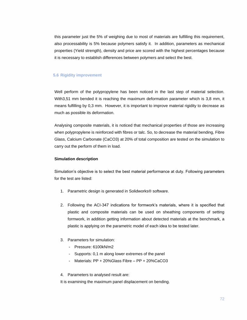
72
this parameter just the 5% of weighing due to most of materials are fulfilling this requirement,
also processability is 5% because polymers satisfy it. In addition, parameters as mechanical
properties (Yield strength), density and price are scored with the highest percentages because
it is necessary to establish differences between polymers and select the best.
5.6 Rigidity improvement
Well perform of the polypropylene has been noticed in the last step of material selection.
With3,51 mm bended it is reaching the maximum deformation parameter which is 3,8 mm, it
means fulfilling by 0,3 mm. However, it is important to improve material rigidity to decrease as
much as possible its deformation.
Analysing composite materials, it is noticed that mechanical properties of those are increasing
when polypropylene is reinforced with fibres or talc. So, to decrease the material bending, Fibre
Glass, Calcium Carbonate (CaCO3) at 20% of total composition are tested on the simulation to
carry out the perform of them in load.
Simulation description
Simulation’s objective is to select the best material performance at duty. Following parameters
for the test are listed:
1. Parametric design is generated in Solidworks® software.
2. Following the ACI-347 indications for formwork’s materials, where it is specified that
plastic and composite materials can be used on sheathing components of setting
formwork, in addition getting information about detected materials at the benchmark, a
plastic is applying on the parametric model of each idea to be tested later.
3. Parameters for simulation:
- Pressure: 6100kN/m2
- Supports: 0,1 m along lower extremes of the panel
- Materials: PP + 20%Glass Fibre – PP + 20%CaCO3
4. Parameters to analysed result are:
It is examining the maximum panel displacement on bending.
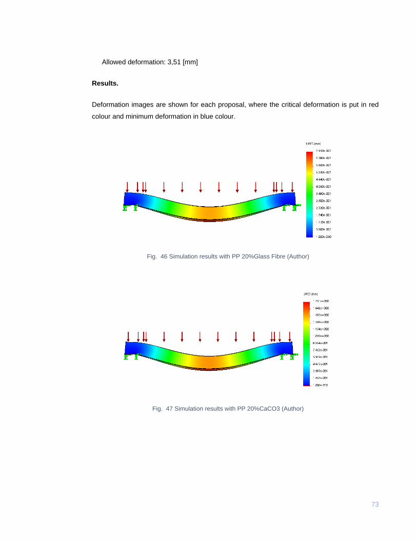
73
Allowed deformation: 3,51 [mm]
Results.
Deformation images are shown for each proposal, where the critical deformation is put in red
colour and minimum deformation in blue colour.
Fig. 46 Simulation results with PP 20%Glass Fibre (Author)
Fig. 47 Simulation results with PP 20%CaCO3 (Author)
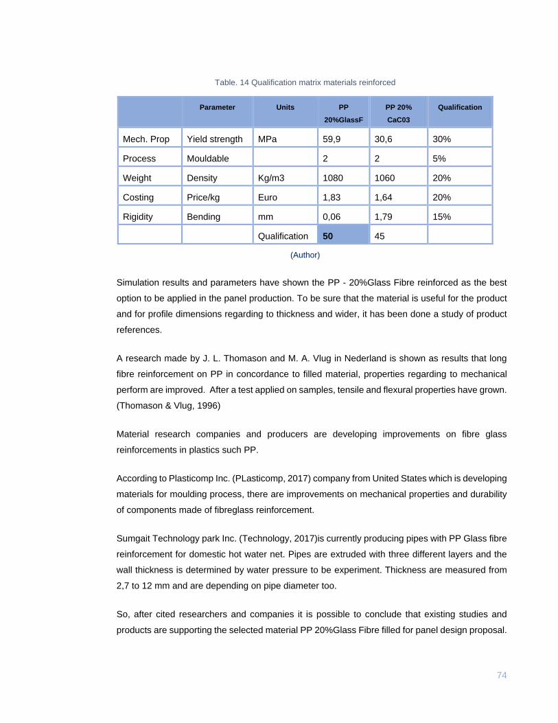
74
Table. 14 Qualification matrix materials reinforced
Parameter Units PP
20%GlassF
PP 20%
CaC03
Qualification
Mech. Prop Yield strength MPa 59,9 30,6 30%
Process Mouldable 2 2 5%
Weight Density Kg/m3 1080 1060 20%
Costing Price/kg Euro 1,83 1,64 20%
Rigidity Bending mm 0,06 1,79 15%
Qualification 50 45
(Author)
Simulation results and parameters have shown the PP - 20%Glass Fibre reinforced as the best
option to be applied in the panel production. To be sure that the material is useful for the product
and for profile dimensions regarding to thickness and wider, it has been done a study of product
references.
A research made by J. L. Thomason and M. A. Vlug in Nederland is shown as results that long
fibre reinforcement on PP in concordance to filled material, properties regarding to mechanical
perform are improved. After a test applied on samples, tensile and flexural properties have grown.
(Thomason & Vlug, 1996)
Material research companies and producers are developing improvements on fibre glass
reinforcements in plastics such PP.
According to Plasticomp Inc. (PLasticomp, 2017) company from United States which is developing
materials for moulding process, there are improvements on mechanical properties and durability
of components made of fibreglass reinforcement.
Sumgait Technology park Inc. (Technology, 2017)is currently producing pipes with PP Glass fibre
reinforcement for domestic hot water net. Pipes are extruded with three different layers and the
wall thickness is determined by water pressure to be experiment. Thickness are measured from
2,7 to 12 mm and are depending on pipe diameter too.
So, after cited researchers and companies it is possible to conclude that existing studies and
products are supporting the selected material PP 20%Glass Fibre filled for panel design proposal.
75
5.7 Panel approximated production costing per square meter
To estimate the product costing, parameters to evaluate have been set in CES Edupack software.
To compare price per panel, it has done a quotation of a current module produced by injection
moulding at Geoplast company which was cited in the benchmark as product reference.
Quotation has been done by a website of the company (Adtomall, 2018) where it was specified
the following info:
Minimum order: 100 m2
Price / m2: 45€
Panel cover area: 0,96 m2
Number of panels: 1042
To do a comparison between current products and panel’s design proposal, the costing analysis
at the software is given by the parameters:
Batch: 10000 pz.
Capital write-off time: 10 years
Component length: 1,4 m
Component mass: 18,4 kg
Discount rate: 5%
Load Factor: 0,5
Material cost: 1,8 €/kg
Overhead rate: 131,4 €/hr
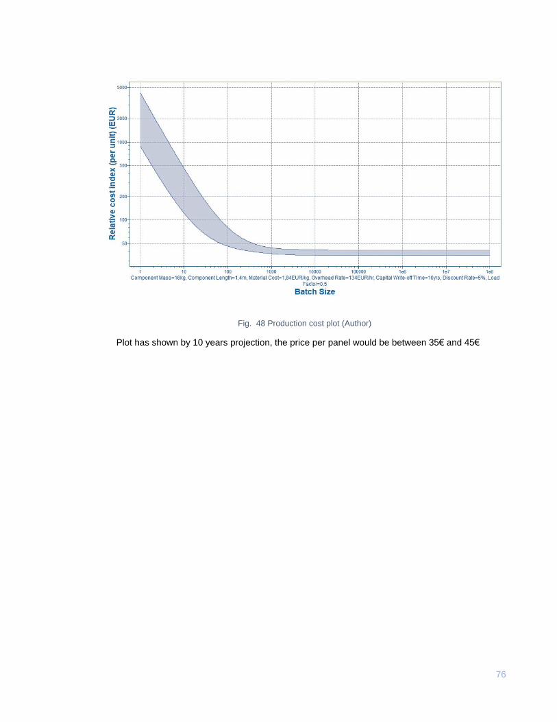
76
Fig. 48 Production cost plot (Author)
Plot has shown by 10 years projection, the price per panel would be between 35€ and 45€
77
6. CONCLUSIONS
It has been realized a literature analysis and interviews with workers and experts in construction
where is was investigate types of formwork and their use into the workout, in addition it was inquire
into problems of moulding for fresh concrete during use and dismount of the system. In consequence
there was stablished needs and linked design requirements to maintenance and number of uses of
panels on duty. Nevertheless, it was determined the main inconvenient regarding to plyboard material
(wood) and environmental conditions which are affecting itself by the use and time.
It was done a concept generation to give problems solution. A validation of generated ideas was
realised where profiles, and performance on duty were checked to select a final concept. In addition,
the bets concept has been developed in detail to achieve design parameters.
Mechanical performance has been calculated through CAD/CAM where final 3D modelling of the
panel was tested in a static simulation at Solidworks® software. The module has settled under
pressure of 6100 N/m2 where results have shown that panel accomplishes with the supporting of
applied load by fresh concrete and formwork system components with a maximum deformation of
0,06 mm.
A costing approximation has been calculated at CES Edupack software to compare the process cost
with a current product on the market. It was stablished that production cost for the proposed panel is
roundly 40€. However final price per square meter of the actual product in plastic is 58€, it would be
pertinent to realize a later costing analysis to stablish the final price for the Plastic Panel for Slab
Formwork.
78
6.1 Limitations
During the project development, it was noticed the need to be in permanent contact with direct
users of the formwork, but it was not possible because geographical inconvenient. Although an
expert was always helping through callings and emails; to be inside this kind of construction filed
would give more information to stablish a better solution and product proposal.
Despite it was gotten info regarding to current products in the market, patents and researching in
formwork for concrete, cough data from companies was limited because there were brochures
with general contain but neither materials specifications, not prices were showed on those.
The production of a prototype was not possible because it wasn’t a sponsor who hold it to do a
physical test. However, expert’s support and got info from them was not paid.
6.2 Future work
Workers and experts have expressed their interest in the production of the plastic panel. They
have told that it would help the work at slabs casting. In addition, they have suggested to proposing
moulds also for columns and beams. Most of them have agreed with a business model regarding
to renting of plastic formwork for concrete at those regions due to the far distances from main
cities of the country. So, it is proposed to continue the panel’s research and development to satisfy
those needs expressed by people who work at construction field in faraway zones of Colombia.
79
BIBLIOGRAPHY
ACI 347, commitee. (2004). ACI 347R-14 Guide to Formwork for Concrete, 4(15-10–2004), 32.
Application, F., Data, P., Smith, C. H., Rosen, M., Carl, H., Conf, P. A., & Eisenzopf, P. E. J. (1985).
United States Patent (19), 35(7), 886–890.
Bralla, J. R. C. (2004a). Injection-molded thermoplastic parts. Design for Manufacturability Handbook,
24.
Bralla, J. R. C. (2004b). Plastic Profile Extrusions. Library, 99–108.
DANE. (2016). Boletín técnico Vivienda VIS y No VIS, 1–39.
Giraldo, H. (n.d.). ¿Como Se Predimensiona Una Estructura?
Hanna, A. S. (1999). Concrete Formwork Svstems Library of Congress Cataloging-in-Publication
Data.
Hodska, N. S. ; (2004). Blow-Molded Plastic Parts. Library, 67–74.
Jiaping, M. I. (1994). DEVELOPMENT AND TREND OF NEW TYPE FORMWORK, 546–549.
Johnston, D. W. (2010). Design and Construction of Concrete Formwork.
Kong, S., Application, F., & Data, P. (2011). ( 12 ) United States Patent, 2(12), 12–15.
https://doi.org/10.1016/j.(73)
MRU. (2018). APA for Academic Writing ( 2017-2018 ) The Purpose of Referencing / Documentation
Avoiding Plagiarism – Citation Principles for Essays and Term Papers Referencing / Citing
Sources within Your Paper, 1–11.
SCI, S. C. de I. (1997a). NSR-10, A.
SCI, S. C. de I. (1997b). NSR-10, C, 530–827.
Segura, J. (1999). Estructuras en Concreto I.
80
Subsidiarios, Y. O., & Mexicanos, D. E. P. (2006). Diseño de estructuras de concreto. Society (Vol.
25). https://doi.org/10.1006/prep.2002.1627\rS104659280291627X [pii]
Thomason, J. L., & Vlug, M. A. (1996). Influence of fibre length and concentration on the properties
of glass fibre-reinforced polypropylene: 1. Tensile and flexural modulus. Composites Part A:
Applied Science and Manufacturing, 27(6), 477–484. https://doi.org/10.1016/1359-
835X(95)00065-A
Ulrich, K. T., & Eppinger, S. D. (2009). Product development and computer aided design. Manual of
Engineering Drawing. https://doi.org/10.1016/B978-0-7506-8985-4.00002-4
Adtomall. (2018). Adtomall.com. Retrieved from http://www.adtomall.com/plastic-formwork
Alibaba. (2018). Alibaba. Retrieved from https://www.alibaba.com/showroom/wpc-decking.html
Chachareros. (2015, 10). La chachara.org. Retrieved from
http://lachachara.org/2015/10/construferia-de-vivienda-de-interes-social/
CORDECK. (2017). CORDECK.COM. Retrieved from http://www.cordeck.com/metal-deck-systems
DSCAFF. (2017). dscaff.com. Retrieved from http://www.dscaff.com/our-products/sbs-plastic-
formwork/
Gelvez, J. (2017, October). Structural Ingeenier. (P. Gelvez, Interviewer)
Hunnebeck. (2017). Hunnebeck.co.uk. Retrieved from hunnebeck.co.uk/products-solutions/slab-
formwork/topec
MEVA. (2017). MEVA INTERNATIONAL. Retrieved from meva-international.com/en/index.php
PBS. (2015). Twitter. Retrieved from https://pbs.twimg.com/media/ApiRtyXCQAAWdrK.jpg
PLasticomp. (2017). Plasticomp.com. Retrieved from http://www.plasticomp.com/long-fiber-benefits/
Plasticpiling.co. (2016). Plasticpiling. Retrieved from http://www.plasticpiling.co.uk/plastic-sheet-
piling/
Plastipolsa. (2012). Plastipolsa s.a. Retrieved from http://www.construplastcolombia.com/

81
Precast, G. (2017). Gulf Precast. Retrieved from http://www.gulfprecast.ae/beams-columns-2/
Technology, S. (2017). Sumgait Technology Park. Retrieved from https://www.stp.az/
Wikipedia. (2018). Wikipedia.org. Retrieved from
https://commons.wikimedia.org/wiki/File:Puente_de_los_Tilos.jpg

82
ANEXOS
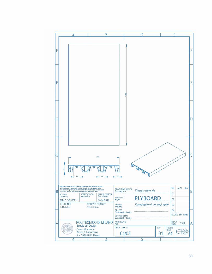
83
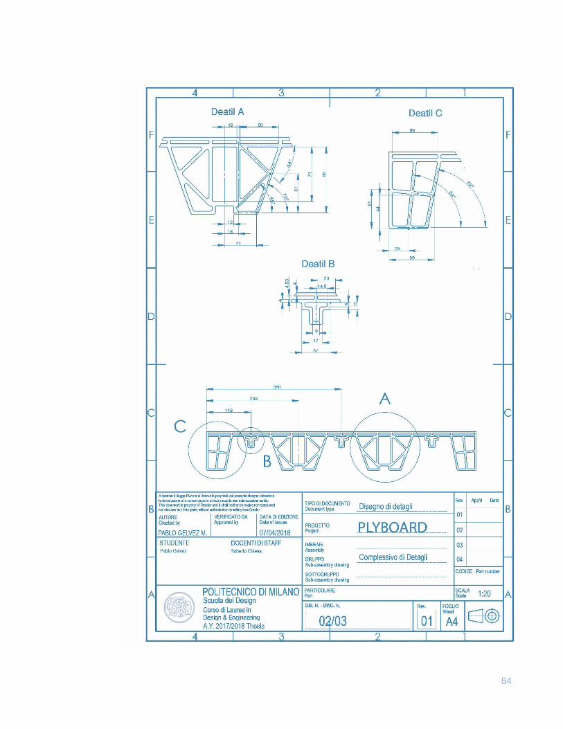
84
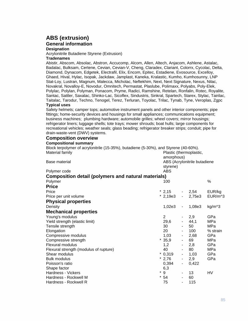
85
ABS (extrusion) General information Designation Acrylonitrile Butadiene Styrene (Extrusion) Tradenames Abistir, Abscom, Absolac, Abstron, Accucomp, Alcom, Allen, Altech, Anjacom, Ashlene, Astalac, Badalac, Bulksam, Certene, Cevian, Cevian-V, Cheng, Claradex, Clariant, Colorrx, Cycolac, Delta, Diamond, Dynacom, Edgetek, Electrafil, Elix, Encom, Epitec, Estadiene, Evosource, Excelloy, Ghaed, Hival, Hylac, Isopak, Jackdaw, Jamplast, Kaneka, Kralastic, Kumho, Kumhosunny, LNP Stat-Loy, Lustran, Magnum, Malecca, Micholac, Neftekhim, Next, Next Signature, Nexus, Nilac, Novakral, Novalloy-E, Novodur, Omnitech, Permastat, Plaslube, Polimaxx, Polyabs, Poly-Elek, Polylac, Polylan, Polyman, Ponacom, Pryme, Radici, Ramshine, Retelan, Ronfalin, Rotec, Royalite, Santac, Sattler, Saxalac, Shinko-Lac, Sicoflex, Sindustris, Sinkral, Spartech, Starex, Stylac, Tairilac, Taitalac, Tarodur, Techno, Tenogel, Terez, Terluran, Toyolac, Trilac, Tynab, Tyne, Veroplas, Zgpc Typical uses Safety helmets; camper tops; automotive instrument panels and other interior components; pipe fittings; home-security devices and housings for small appliances; communications equipment; business machines; plumbing hardware; automobile grilles; wheel covers; mirror housings; refrigerator liners; luggage shells; tote trays; mower shrouds; boat hulls; large components for recreational vehicles; weather seals; glass beading; refrigerator breaker strips; conduit; pipe for drain-waste-vent (DWV) systems.
Composition overview Compositional summary Block terpolymer of acrylonitrile (15-35%), butadiene (5-30%), and Styrene (40-60%). Material family Plastic (thermoplastic,
amorphous) Base material ABS (Acrylonitrile butadiene
styrene) Polymer code ABS
Composition detail (polymers and natural materials) Polymer 100 %
Price Price * 2,15 - 2,54 EUR/kg Price per unit volume * 2,19e3 - 2,75e3 EUR/m^3
Physical properties Density 1,02e3 - 1,08e3 kg/m^3
Mechanical properties Young's modulus 2 - 2,9 GPa Yield strength (elastic limit) 29,6 - 44,1 MPa Tensile strength 30 - 50 MPa Elongation 20 - 100 % strain Compressive modulus 1,03 - 2,68 GPa Compressive strength * 35,9 - 69 MPa Flexural modulus 1,2 - 2,8 GPa Flexural strength (modulus of rupture) 40 - 80 MPa Shear modulus * 0,319 - 1,03 GPa Bulk modulus * 2,76 - 2,9 GPa Poisson's ratio 0,394 - 0,422 Shape factor 6,3 Hardness - Vickers * 9 - 13 HV Hardness - Rockwell M * 54 - 60 Hardness - Rockwell R 75 - 115
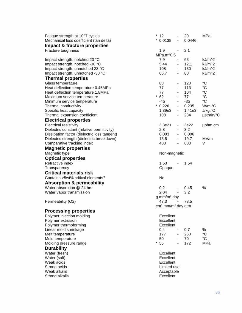
86
Fatigue strength at 10^7 cycles * 12 - 20 MPa Mechanical loss coefficient (tan delta) * 0,0138 - 0,0446
Impact & fracture properties Fracture toughness 1,9 - 2,1 MPa.m^0.5 Impact strength, notched 23 °C 7,9 - 63 kJ/m^2 Impact strength, notched -30 °C 5,44 - 12,1 kJ/m^2 Impact strength, unnotched 23 °C 108 - 130 kJ/m^2 Impact strength, unnotched -30 °C 66,7 - 80 kJ/m^2
Thermal properties Glass temperature 88 - 120 °C Heat deflection temperature 0.45MPa 77 - 113 °C Heat deflection temperature 1.8MPa 77 - 104 °C Maximum service temperature * 62 - 77 °C Minimum service temperature -45 - -35 °C Thermal conductivity * 0,226 - 0,235 W/m.°C Specific heat capacity 1,39e3 - 1,41e3 J/kg.°C Thermal expansion coefficient 108 - 234 µstrain/°C
Electrical properties Electrical resistivity 3,3e21 - 3e22 µohm.cm Dielectric constant (relative permittivity) 2,8 - 3,2 Dissipation factor (dielectric loss tangent) 0,003 - 0,006 Dielectric strength (dielectric breakdown) 13,8 - 19,7 MV/m Comparative tracking index 400 - 600 V
Magnetic properties Magnetic type Non-magnetic
Optical properties Refractive index 1,53 - 1,54 Transparency Opaque
Critical materials risk Contains >5wt% critical elements? No
Absorption & permeability Water absorption @ 24 hrs 0,2 - 0,45 % Water vapor transmission 2,04 - 3,2 g.mm/m².day Permeability (O2) 47,3 - 78,5 cm³.mm/m².day.atm
Processing properties Polymer injection molding Excellent Polymer extrusion Excellent Polymer thermoforming Excellent Linear mold shrinkage 0,4 - 0,7 % Melt temperature 177 - 260 °C Mold temperature 50 - 70 °C Molding pressure range * 55 - 172 MPa
Durability Water (fresh) Excellent Water (salt) Excellent Weak acids Excellent Strong acids Limited use Weak alkalis Acceptable Strong alkalis Excellent
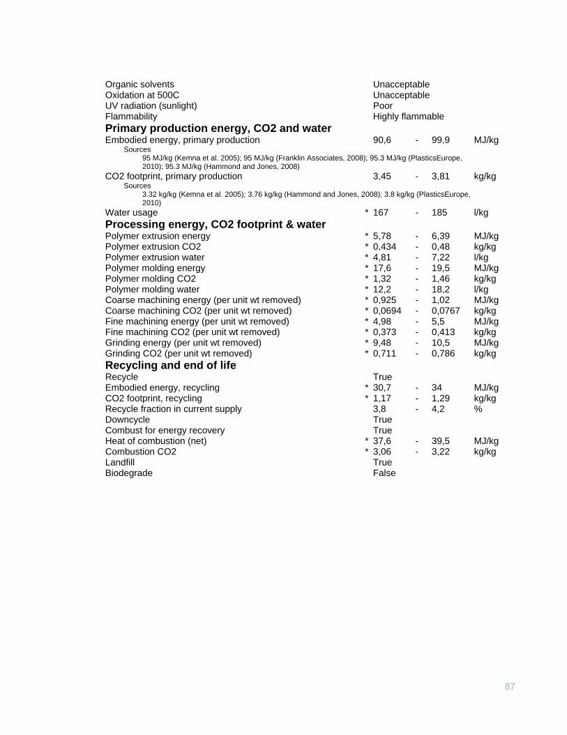
87
Organic solvents Unacceptable Oxidation at 500C Unacceptable UV radiation (sunlight) Poor Flammability Highly flammable
Primary production energy, CO2 and water Embodied energy, primary production 90,6 - 99,9 MJ/kg
Sources 95 MJ/kg (Kemna et al. 2005); 95 MJ/kg (Franklin Associates, 2008); 95.3 MJ/kg (PlasticsEurope, 2010); 95.3 MJ/kg (Hammond and Jones, 2008)
CO2 footprint, primary production 3,45 - 3,81 kg/kg Sources
3.32 kg/kg (Kemna et al. 2005); 3.76 kg/kg (Hammond and Jones, 2008); 3.8 kg/kg (PlasticsEurope, 2010)
Water usage * 167 - 185 l/kg
Processing energy, CO2 footprint & water Polymer extrusion energy * 5,78 - 6,39 MJ/kg Polymer extrusion CO2 * 0,434 - 0,48 kg/kg Polymer extrusion water * 4,81 - 7,22 l/kg Polymer molding energy * 17,6 - 19,5 MJ/kg Polymer molding CO2 * 1,32 - 1,46 kg/kg Polymer molding water * 12,2 - 18,2 l/kg Coarse machining energy (per unit wt removed) * 0,925 - 1,02 MJ/kg Coarse machining CO2 (per unit wt removed) * 0,0694 - 0,0767 kg/kg Fine machining energy (per unit wt removed) * 4,98 - 5,5 MJ/kg Fine machining CO2 (per unit wt removed) * 0,373 - 0,413 kg/kg Grinding energy (per unit wt removed) * 9,48 - 10,5 MJ/kg Grinding CO2 (per unit wt removed) * 0,711 - 0,786 kg/kg
Recycling and end of life Recycle True Embodied energy, recycling * 30,7 - 34 MJ/kg CO2 footprint, recycling * 1,17 - 1,29 kg/kg Recycle fraction in current supply 3,8 - 4,2 % Downcycle True Combust for energy recovery True Heat of combustion (net) * 37,6 - 39,5 MJ/kg Combustion CO2 * 3,06 - 3,22 kg/kg Landfill True Biodegrade False
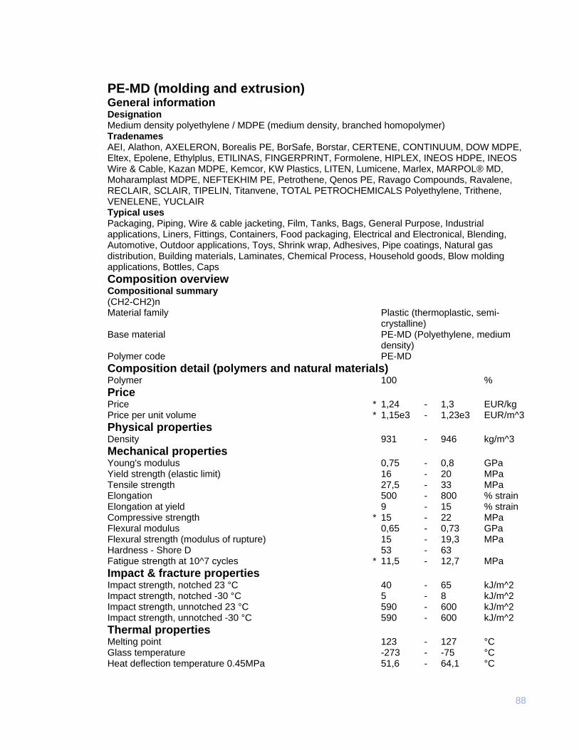
88
PE-MD (molding and extrusion) General information Designation Medium density polyethylene / MDPE (medium density, branched homopolymer) Tradenames AEI, Alathon, AXELERON, Borealis PE, BorSafe, Borstar, CERTENE, CONTINUUM, DOW MDPE, Eltex, Epolene, Ethylplus, ETILINAS, FINGERPRINT, Formolene, HIPLEX, INEOS HDPE, INEOS Wire & Cable, Kazan MDPE, Kemcor, KW Plastics, LITEN, Lumicene, Marlex, MARPOL® MD, Moharamplast MDPE, NEFTEKHIM PE, Petrothene, Qenos PE, Ravago Compounds, Ravalene, RECLAIR, SCLAIR, TIPELIN, Titanvene, TOTAL PETROCHEMICALS Polyethylene, Trithene, VENELENE, YUCLAIR Typical uses Packaging, Piping, Wire & cable jacketing, Film, Tanks, Bags, General Purpose, Industrial applications, Liners, Fittings, Containers, Food packaging, Electrical and Electronical, Blending, Automotive, Outdoor applications, Toys, Shrink wrap, Adhesives, Pipe coatings, Natural gas distribution, Building materials, Laminates, Chemical Process, Household goods, Blow molding applications, Bottles, Caps
Composition overview Compositional summary (CH2-CH2)n Material family Plastic (thermoplastic, semi-
crystalline) Base material PE-MD (Polyethylene, medium
density) Polymer code PE-MD
Composition detail (polymers and natural materials) Polymer 100 %
Price Price * 1,24 - 1,3 EUR/kg Price per unit volume * 1,15e3 - 1,23e3 EUR/m^3
Physical properties Density 931 - 946 kg/m^3
Mechanical properties Young's modulus 0,75 - 0,8 GPa Yield strength (elastic limit) 16 - 20 MPa Tensile strength 27,5 - 33 MPa Elongation 500 - 800 % strain Elongation at yield 9 - 15 % strain Compressive strength * 15 - 22 MPa Flexural modulus 0,65 - 0,73 GPa Flexural strength (modulus of rupture) 15 - 19,3 MPa Hardness - Shore D 53 - 63 Fatigue strength at 10^7 cycles * 11,5 - 12,7 MPa
Impact & fracture properties Impact strength, notched 23 °C 40 - 65 kJ/m^2 Impact strength, notched -30 °C 5 - 8 kJ/m^2 Impact strength, unnotched 23 °C 590 - 600 kJ/m^2 Impact strength, unnotched -30 °C 590 - 600 kJ/m^2
Thermal properties Melting point 123 - 127 °C Glass temperature -273 - -75 °C Heat deflection temperature 0.45MPa 51,6 - 64,1 °C
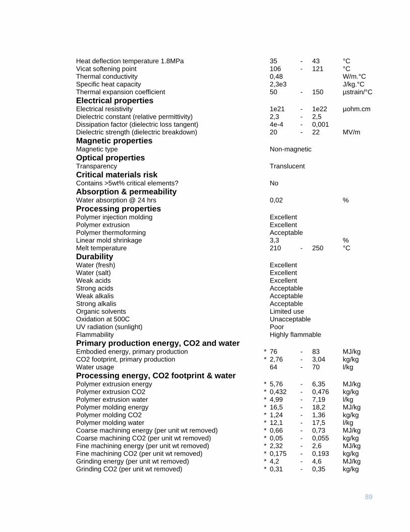
89
Heat deflection temperature 1.8MPa 35 - 43 °C Vicat softening point 106 - 121 °C Thermal conductivity 0,48 W/m.°C Specific heat capacity 2,3e3 J/kg.°C Thermal expansion coefficient 50 - 150 µstrain/°C
Electrical properties Electrical resistivity 1e21 - 1e22 µohm.cm Dielectric constant (relative permittivity) 2,3 - 2,5 Dissipation factor (dielectric loss tangent) 4e-4 - 0,001 Dielectric strength (dielectric breakdown) 20 - 22 MV/m
Magnetic properties Magnetic type Non-magnetic
Optical properties Transparency Translucent
Critical materials risk Contains >5wt% critical elements? No
Absorption & permeability Water absorption @ 24 hrs 0,02 %
Processing properties Polymer injection molding Excellent Polymer extrusion Excellent Polymer thermoforming Acceptable Linear mold shrinkage 3,3 % Melt temperature 210 - 250 °C
Durability Water (fresh) Excellent Water (salt) Excellent Weak acids Excellent Strong acids Acceptable Weak alkalis Acceptable Strong alkalis Acceptable Organic solvents Limited use Oxidation at 500C Unacceptable UV radiation (sunlight) Poor Flammability Highly flammable
Primary production energy, CO2 and water Embodied energy, primary production * 76 - 83 MJ/kg CO2 footprint, primary production * 2,76 - 3,04 kg/kg Water usage 64 - 70 l/kg
Processing energy, CO2 footprint & water Polymer extrusion energy * 5,76 - 6,35 MJ/kg Polymer extrusion CO2 * 0,432 - 0,476 kg/kg Polymer extrusion water * 4,99 - 7,19 l/kg Polymer molding energy * 16,5 - 18,2 MJ/kg Polymer molding CO2 * 1,24 - 1,36 kg/kg Polymer molding water * 12,1 - 17,5 l/kg Coarse machining energy (per unit wt removed) * 0,66 - 0,73 MJ/kg Coarse machining CO2 (per unit wt removed) * 0,05 - 0,055 kg/kg Fine machining energy (per unit wt removed) * 2,32 - 2,6 MJ/kg Fine machining CO2 (per unit wt removed) * 0,175 - 0,193 kg/kg Grinding energy (per unit wt removed) * 4,2 - 4,6 MJ/kg Grinding CO2 (per unit wt removed) * 0,31 - 0,35 kg/kg
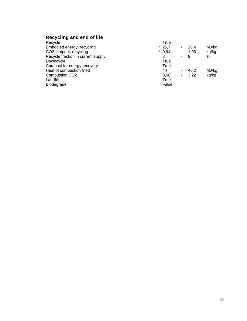
90
Recycling and end of life Recycle True Embodied energy, recycling * 25,7 - 28,4 MJ/kg CO2 footprint, recycling * 0,94 - 1,03 kg/kg Recycle fraction in current supply 8 - 9 % Downcycle True Combust for energy recovery True Heat of combustion (net) 44 - 46,2 MJ/kg Combustion CO2 3,06 - 3,22 kg/kg Landfill True Biodegrade False
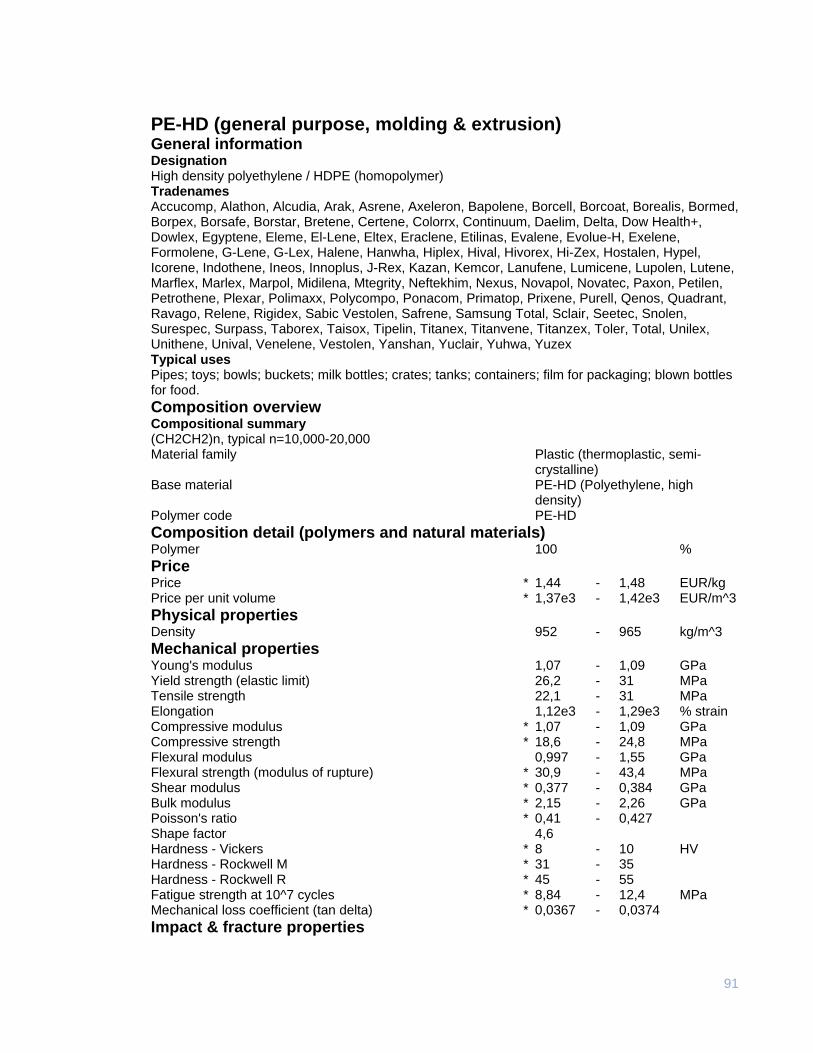
91
PE-HD (general purpose, molding & extrusion) General information Designation High density polyethylene / HDPE (homopolymer) Tradenames Accucomp, Alathon, Alcudia, Arak, Asrene, Axeleron, Bapolene, Borcell, Borcoat, Borealis, Bormed, Borpex, Borsafe, Borstar, Bretene, Certene, Colorrx, Continuum, Daelim, Delta, Dow Health+, Dowlex, Egyptene, Eleme, El-Lene, Eltex, Eraclene, Etilinas, Evalene, Evolue-H, Exelene, Formolene, G-Lene, G-Lex, Halene, Hanwha, Hiplex, Hival, Hivorex, Hi-Zex, Hostalen, Hypel, Icorene, Indothene, Ineos, Innoplus, J-Rex, Kazan, Kemcor, Lanufene, Lumicene, Lupolen, Lutene, Marflex, Marlex, Marpol, Midilena, Mtegrity, Neftekhim, Nexus, Novapol, Novatec, Paxon, Petilen, Petrothene, Plexar, Polimaxx, Polycompo, Ponacom, Primatop, Prixene, Purell, Qenos, Quadrant, Ravago, Relene, Rigidex, Sabic Vestolen, Safrene, Samsung Total, Sclair, Seetec, Snolen, Surespec, Surpass, Taborex, Taisox, Tipelin, Titanex, Titanvene, Titanzex, Toler, Total, Unilex, Unithene, Unival, Venelene, Vestolen, Yanshan, Yuclair, Yuhwa, Yuzex Typical uses Pipes; toys; bowls; buckets; milk bottles; crates; tanks; containers; film for packaging; blown bottles for food.
Composition overview Compositional summary (CH2CH2)n, typical n=10,000-20,000 Material family Plastic (thermoplastic, semi-
crystalline) Base material PE-HD (Polyethylene, high
density) Polymer code PE-HD
Composition detail (polymers and natural materials) Polymer 100 %
Price Price * 1,44 - 1,48 EUR/kg Price per unit volume * 1,37e3 - 1,42e3 EUR/m^3
Physical properties Density 952 - 965 kg/m^3
Mechanical properties Young's modulus 1,07 - 1,09 GPa Yield strength (elastic limit) 26,2 - 31 MPa Tensile strength 22,1 - 31 MPa Elongation 1,12e3 - 1,29e3 % strain Compressive modulus * 1,07 - 1,09 GPa Compressive strength * 18,6 - 24,8 MPa Flexural modulus 0,997 - 1,55 GPa Flexural strength (modulus of rupture) * 30,9 - 43,4 MPa Shear modulus * 0,377 - 0,384 GPa Bulk modulus * 2,15 - 2,26 GPa Poisson's ratio * 0,41 - 0,427 Shape factor 4,6 Hardness - Vickers * 8 - 10 HV Hardness - Rockwell M * 31 - 35 Hardness - Rockwell R * 45 - 55 Fatigue strength at 10^7 cycles * 8,84 - 12,4 MPa Mechanical loss coefficient (tan delta) * 0,0367 - 0,0374
Impact & fracture properties
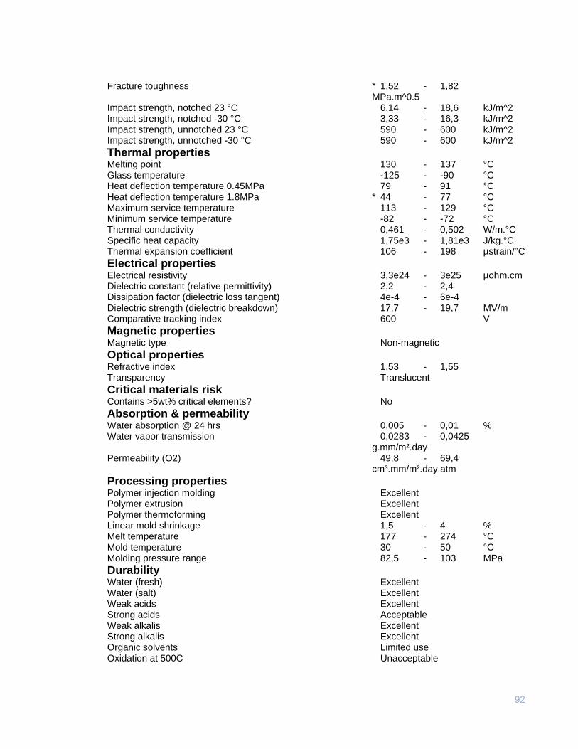
92
Fracture toughness * 1,52 - 1,82 MPa.m^0.5 Impact strength, notched 23 °C 6,14 - 18,6 kJ/m^2 Impact strength, notched -30 °C 3,33 - 16,3 kJ/m^2 Impact strength, unnotched 23 °C 590 - 600 kJ/m^2 Impact strength, unnotched -30 °C 590 - 600 kJ/m^2
Thermal properties Melting point 130 - 137 °C Glass temperature -125 - -90 °C Heat deflection temperature 0.45MPa 79 - 91 °C Heat deflection temperature 1.8MPa * 44 - 77 °C Maximum service temperature 113 - 129 °C Minimum service temperature -82 - -72 °C Thermal conductivity 0,461 - 0,502 W/m.°C Specific heat capacity 1,75e3 - 1,81e3 J/kg.°C Thermal expansion coefficient 106 - 198 µstrain/°C
Electrical properties Electrical resistivity 3,3e24 - 3e25 µohm.cm Dielectric constant (relative permittivity) 2,2 - 2,4 Dissipation factor (dielectric loss tangent) 4e-4 - 6e-4 Dielectric strength (dielectric breakdown) 17,7 - 19,7 MV/m Comparative tracking index 600 V
Magnetic properties Magnetic type Non-magnetic
Optical properties Refractive index 1,53 - 1,55 Transparency Translucent
Critical materials risk Contains >5wt% critical elements? No
Absorption & permeability Water absorption @ 24 hrs 0,005 - 0,01 % Water vapor transmission 0,0283 - 0,0425 g.mm/m².day Permeability (O2) 49,8 - 69,4 cm³.mm/m².day.atm
Processing properties Polymer injection molding Excellent Polymer extrusion Excellent Polymer thermoforming Excellent Linear mold shrinkage 1,5 - 4 % Melt temperature 177 - 274 °C Mold temperature 30 - 50 °C Molding pressure range 82,5 - 103 MPa
Durability Water (fresh) Excellent Water (salt) Excellent Weak acids Excellent Strong acids Acceptable Weak alkalis Excellent Strong alkalis Excellent Organic solvents Limited use Oxidation at 500C Unacceptable
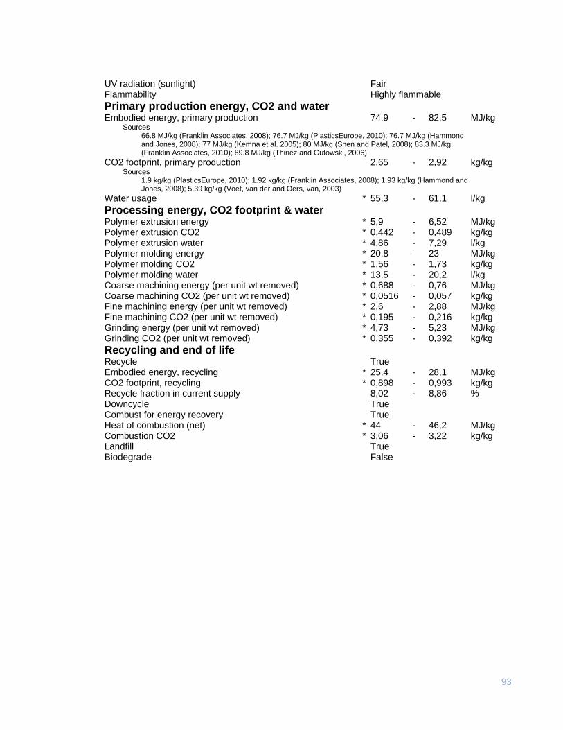
93
UV radiation (sunlight) Fair Flammability Highly flammable
Primary production energy, CO2 and water Embodied energy, primary production 74,9 - 82,5 MJ/kg
Sources 66.8 MJ/kg (Franklin Associates, 2008); 76.7 MJ/kg (PlasticsEurope, 2010); 76.7 MJ/kg (Hammond and Jones, 2008); 77 MJ/kg (Kemna et al. 2005); 80 MJ/kg (Shen and Patel, 2008); 83.3 MJ/kg (Franklin Associates, 2010); 89.8 MJ/kg (Thiriez and Gutowski, 2006)
CO2 footprint, primary production 2,65 - 2,92 kg/kg Sources
1.9 kg/kg (PlasticsEurope, 2010); 1.92 kg/kg (Franklin Associates, 2008); 1.93 kg/kg (Hammond and Jones, 2008); 5.39 kg/kg (Voet, van der and Oers, van, 2003)
Water usage * 55,3 - 61,1 l/kg
Processing energy, CO2 footprint & water Polymer extrusion energy * 5,9 - 6,52 MJ/kg Polymer extrusion CO2 * 0,442 - 0,489 kg/kg Polymer extrusion water * 4,86 - 7,29 l/kg Polymer molding energy * 20,8 - 23 MJ/kg Polymer molding CO2 * 1,56 - 1,73 kg/kg Polymer molding water * 13,5 - 20,2 l/kg Coarse machining energy (per unit wt removed) * 0,688 - 0,76 MJ/kg Coarse machining CO2 (per unit wt removed) * 0,0516 - 0,057 kg/kg Fine machining energy (per unit wt removed) * 2,6 - 2,88 MJ/kg Fine machining CO2 (per unit wt removed) * 0,195 - 0,216 kg/kg Grinding energy (per unit wt removed) * 4,73 - 5,23 MJ/kg Grinding CO2 (per unit wt removed) * 0,355 - 0,392 kg/kg
Recycling and end of life Recycle True Embodied energy, recycling * 25,4 - 28,1 MJ/kg CO2 footprint, recycling * 0,898 - 0,993 kg/kg Recycle fraction in current supply 8,02 - 8,86 % Downcycle True Combust for energy recovery True Heat of combustion (net) * 44 - 46,2 MJ/kg Combustion CO2 * 3,06 - 3,22 kg/kg Landfill True Biodegrade False
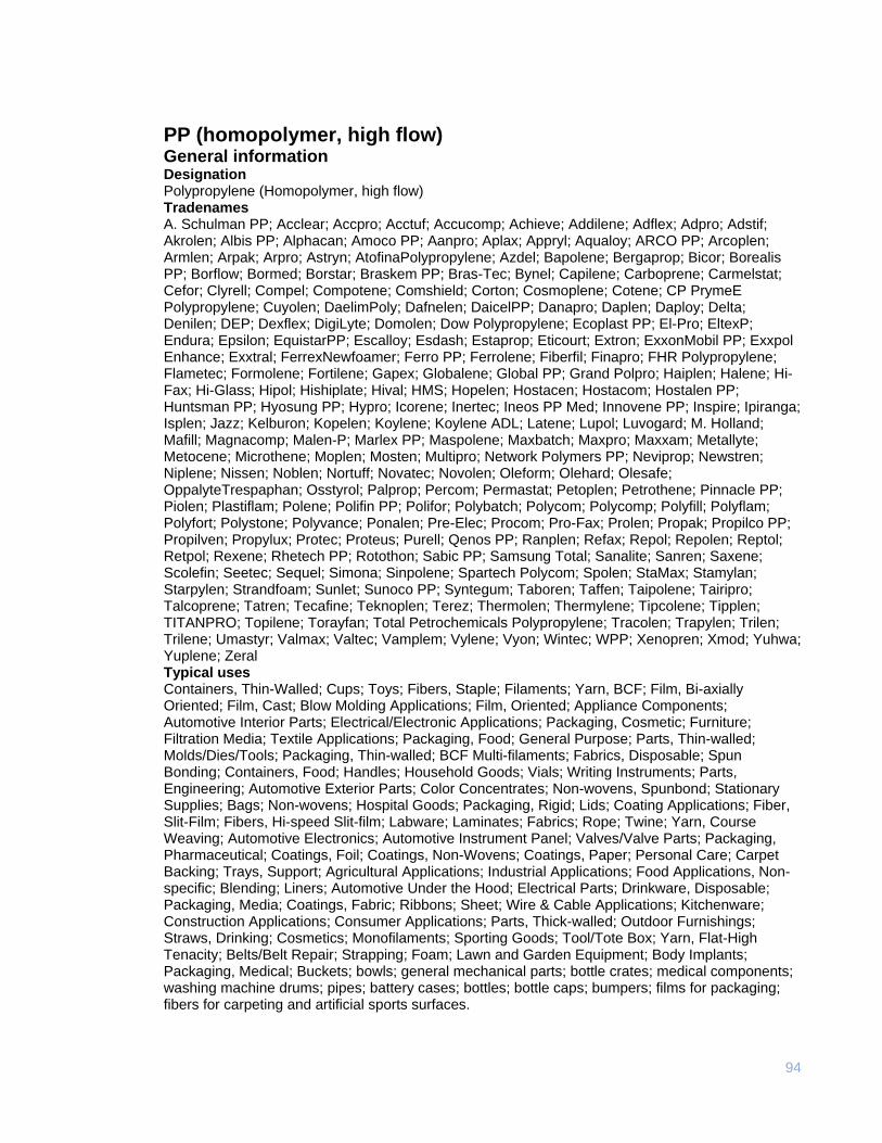
94
PP (homopolymer, high flow) General information Designation Polypropylene (Homopolymer, high flow) Tradenames A. Schulman PP; Acclear; Accpro; Acctuf; Accucomp; Achieve; Addilene; Adflex; Adpro; Adstif; Akrolen; Albis PP; Alphacan; Amoco PP; Aanpro; Aplax; Appryl; Aqualoy; ARCO PP; Arcoplen; Armlen; Arpak; Arpro; Astryn; AtofinaPolypropylene; Azdel; Bapolene; Bergaprop; Bicor; Borealis PP; Borflow; Bormed; Borstar; Braskem PP; Bras-Tec; Bynel; Capilene; Carboprene; Carmelstat; Cefor; Clyrell; Compel; Compotene; Comshield; Corton; Cosmoplene; Cotene; CP PrymeE Polypropylene; Cuyolen; DaelimPoly; Dafnelen; DaicelPP; Danapro; Daplen; Daploy; Delta; Denilen; DEP; Dexflex; DigiLyte; Domolen; Dow Polypropylene; Ecoplast PP; El-Pro; EltexP; Endura; Epsilon; EquistarPP; Escalloy; Esdash; Estaprop; Eticourt; Extron; ExxonMobil PP; Exxpol Enhance; Exxtral; FerrexNewfoamer; Ferro PP; Ferrolene; Fiberfil; Finapro; FHR Polypropylene; Flametec; Formolene; Fortilene; Gapex; Globalene; Global PP; Grand Polpro; Haiplen; Halene; Hi-Fax; Hi-Glass; Hipol; Hishiplate; Hival; HMS; Hopelen; Hostacen; Hostacom; Hostalen PP; Huntsman PP; Hyosung PP; Hypro; Icorene; Inertec; Ineos PP Med; Innovene PP; Inspire; Ipiranga; Isplen; Jazz; Kelburon; Kopelen; Koylene; Koylene ADL; Latene; Lupol; Luvogard; M. Holland; Mafill; Magnacomp; Malen-P; Marlex PP; Maspolene; Maxbatch; Maxpro; Maxxam; Metallyte; Metocene; Microthene; Moplen; Mosten; Multipro; Network Polymers PP; Neviprop; Newstren; Niplene; Nissen; Noblen; Nortuff; Novatec; Novolen; Oleform; Olehard; Olesafe; OppalyteTrespaphan; Osstyrol; Palprop; Percom; Permastat; Petoplen; Petrothene; Pinnacle PP; Piolen; Plastiflam; Polene; Polifin PP; Polifor; Polybatch; Polycom; Polycomp; Polyfill; Polyflam; Polyfort; Polystone; Polyvance; Ponalen; Pre-Elec; Procom; Pro-Fax; Prolen; Propak; Propilco PP; Propilven; Propylux; Protec; Proteus; Purell; Qenos PP; Ranplen; Refax; Repol; Repolen; Reptol; Retpol; Rexene; Rhetech PP; Rotothon; Sabic PP; Samsung Total; Sanalite; Sanren; Saxene; Scolefin; Seetec; Sequel; Simona; Sinpolene; Spartech Polycom; Spolen; StaMax; Stamylan; Starpylen; Strandfoam; Sunlet; Sunoco PP; Syntegum; Taboren; Taffen; Taipolene; Tairipro; Talcoprene; Tatren; Tecafine; Teknoplen; Terez; Thermolen; Thermylene; Tipcolene; Tipplen; TITANPRO; Topilene; Torayfan; Total Petrochemicals Polypropylene; Tracolen; Trapylen; Trilen; Trilene; Umastyr; Valmax; Valtec; Vamplem; Vylene; Vyon; Wintec; WPP; Xenopren; Xmod; Yuhwa; Yuplene; Zeral Typical uses Containers, Thin-Walled; Cups; Toys; Fibers, Staple; Filaments; Yarn, BCF; Film, Bi-axially Oriented; Film, Cast; Blow Molding Applications; Film, Oriented; Appliance Components; Automotive Interior Parts; Electrical/Electronic Applications; Packaging, Cosmetic; Furniture; Filtration Media; Textile Applications; Packaging, Food; General Purpose; Parts, Thin-walled; Molds/Dies/Tools; Packaging, Thin-walled; BCF Multi-filaments; Fabrics, Disposable; Spun Bonding; Containers, Food; Handles; Household Goods; Vials; Writing Instruments; Parts, Engineering; Automotive Exterior Parts; Color Concentrates; Non-wovens, Spunbond; Stationary Supplies; Bags; Non-wovens; Hospital Goods; Packaging, Rigid; Lids; Coating Applications; Fiber, Slit-Film; Fibers, Hi-speed Slit-film; Labware; Laminates; Fabrics; Rope; Twine; Yarn, Course Weaving; Automotive Electronics; Automotive Instrument Panel; Valves/Valve Parts; Packaging, Pharmaceutical; Coatings, Foil; Coatings, Non-Wovens; Coatings, Paper; Personal Care; Carpet Backing; Trays, Support; Agricultural Applications; Industrial Applications; Food Applications, Non-specific; Blending; Liners; Automotive Under the Hood; Electrical Parts; Drinkware, Disposable; Packaging, Media; Coatings, Fabric; Ribbons; Sheet; Wire & Cable Applications; Kitchenware; Construction Applications; Consumer Applications; Parts, Thick-walled; Outdoor Furnishings; Straws, Drinking; Cosmetics; Monofilaments; Sporting Goods; Tool/Tote Box; Yarn, Flat-High Tenacity; Belts/Belt Repair; Strapping; Foam; Lawn and Garden Equipment; Body Implants; Packaging, Medical; Buckets; bowls; general mechanical parts; bottle crates; medical components; washing machine drums; pipes; battery cases; bottles; bottle caps; bumpers; films for packaging; fibers for carpeting and artificial sports surfaces.
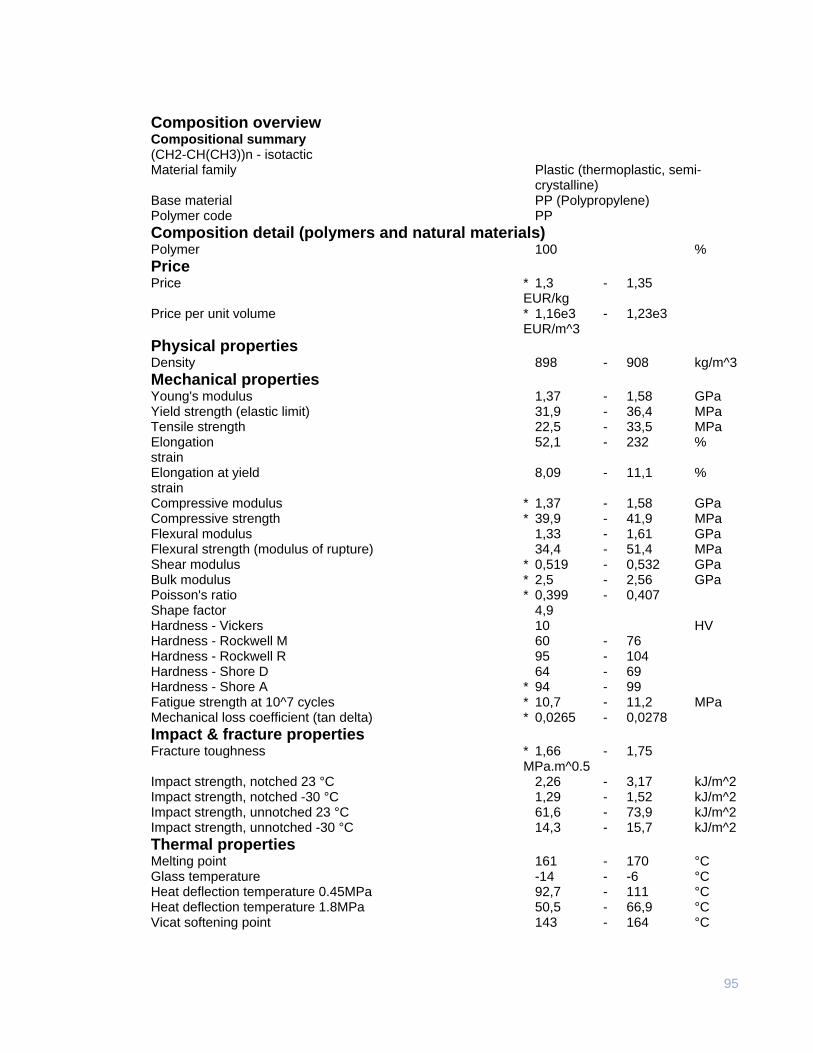
95
Composition overview Compositional summary (CH2-CH(CH3))n - isotactic Material family Plastic (thermoplastic, semi-
crystalline) Base material PP (Polypropylene) Polymer code PP
Composition detail (polymers and natural materials) Polymer 100 %
Price Price * 1,3 - 1,35 EUR/kg Price per unit volume * 1,16e3 - 1,23e3 EUR/m^3
Physical properties Density 898 - 908 kg/m^3
Mechanical properties Young's modulus 1,37 - 1,58 GPa Yield strength (elastic limit) 31,9 - 36,4 MPa Tensile strength 22,5 - 33,5 MPa Elongation 52,1 - 232 % strain Elongation at yield 8,09 - 11,1 % strain Compressive modulus * 1,37 - 1,58 GPa Compressive strength * 39,9 - 41,9 MPa Flexural modulus 1,33 - 1,61 GPa Flexural strength (modulus of rupture) 34,4 - 51,4 MPa Shear modulus * 0,519 - 0,532 GPa Bulk modulus * 2,5 - 2,56 GPa Poisson's ratio * 0,399 - 0,407 Shape factor 4,9 Hardness - Vickers 10 HV Hardness - Rockwell M 60 - 76 Hardness - Rockwell R 95 - 104 Hardness - Shore D 64 - 69 Hardness - Shore A * 94 - 99 Fatigue strength at 10^7 cycles * 10,7 - 11,2 MPa Mechanical loss coefficient (tan delta) * 0,0265 - 0,0278
Impact & fracture properties Fracture toughness * 1,66 - 1,75 MPa.m^0.5 Impact strength, notched 23 °C 2,26 - 3,17 kJ/m^2 Impact strength, notched -30 °C 1,29 - 1,52 kJ/m^2 Impact strength, unnotched 23 °C 61,6 - 73,9 kJ/m^2 Impact strength, unnotched -30 °C 14,3 - 15,7 kJ/m^2
Thermal properties Melting point 161 - 170 °C Glass temperature -14 - -6 °C Heat deflection temperature 0.45MPa 92,7 - 111 °C Heat deflection temperature 1.8MPa 50,5 - 66,9 °C Vicat softening point 143 - 164 °C
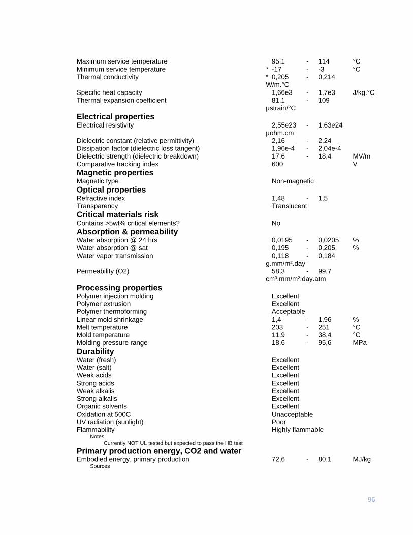
96
Maximum service temperature 95,1 - 114 °C Minimum service temperature * -17 - -3 °C Thermal conductivity * 0,205 - 0,214 W/m.°C Specific heat capacity 1,66e3 - 1,7e3 J/kg.°C Thermal expansion coefficient 81,1 - 109 µstrain/°C
Electrical properties Electrical resistivity 2,55e23 - 1,63e24 µohm.cm Dielectric constant (relative permittivity) 2,16 - 2,24 Dissipation factor (dielectric loss tangent) 1,96e-4 - 2,04e-4 Dielectric strength (dielectric breakdown) 17,6 - 18,4 MV/m Comparative tracking index 600 V
Magnetic properties Magnetic type Non-magnetic
Optical properties Refractive index 1,48 - 1,5 Transparency Translucent
Critical materials risk Contains >5wt% critical elements? No
Absorption & permeability Water absorption @ 24 hrs 0,0195 - 0,0205 % Water absorption @ sat 0,195 - 0,205 % Water vapor transmission 0,118 - 0,184 g.mm/m².day Permeability (O2) 58,3 - 99,7 cm³.mm/m².day.atm
Processing properties Polymer injection molding Excellent Polymer extrusion Excellent Polymer thermoforming Acceptable Linear mold shrinkage 1,4 - 1,96 % Melt temperature 203 - 251 °C Mold temperature 11,9 - 38,4 °C Molding pressure range 18,6 - 95,6 MPa
Durability Water (fresh) Excellent Water (salt) Excellent Weak acids Excellent Strong acids Excellent Weak alkalis Excellent Strong alkalis Excellent Organic solvents Excellent Oxidation at 500C Unacceptable UV radiation (sunlight) Poor Flammability Highly flammable
Notes Currently NOT UL tested but expected to pass the HB test
Primary production energy, CO2 and water Embodied energy, primary production 72,6 - 80,1 MJ/kg
Sources
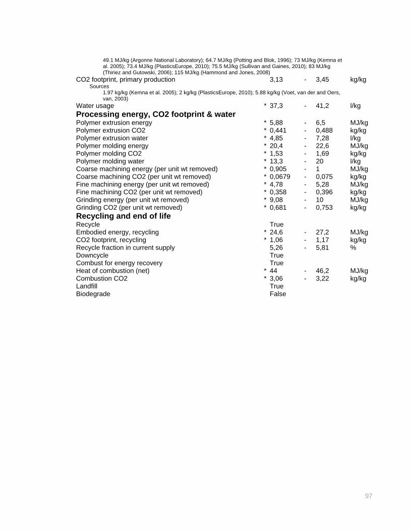
97
49.1 MJ/kg (Argonne National Laboratory); 64.7 MJ/kg (Potting and Blok, 1996); 73 MJ/kg (Kemna et al. 2005); 73.4 MJ/kg (PlasticsEurope, 2010); 75.5 MJ/kg (Sullivan and Gaines, 2010); 83 MJ/kg (Thiriez and Gutowski, 2006); 115 MJ/kg (Hammond and Jones, 2008)
CO2 footprint, primary production 3,13 - 3,45 kg/kg Sources
1.97 kg/kg (Kemna et al. 2005); 2 kg/kg (PlasticsEurope, 2010); 5.88 kg/kg (Voet, van der and Oers, van, 2003)
Water usage * 37,3 - 41,2 l/kg
Processing energy, CO2 footprint & water Polymer extrusion energy * 5,88 - 6,5 MJ/kg Polymer extrusion CO2 * 0,441 - 0,488 kg/kg Polymer extrusion water * 4,85 - 7,28 l/kg Polymer molding energy * 20,4 - 22,6 MJ/kg Polymer molding CO2 * 1,53 - 1,69 kg/kg Polymer molding water * 13,3 - 20 l/kg Coarse machining energy (per unit wt removed) * 0,905 - 1 MJ/kg Coarse machining CO2 (per unit wt removed) * 0,0679 - 0,075 kg/kg Fine machining energy (per unit wt removed) * 4,78 - 5,28 MJ/kg Fine machining CO2 (per unit wt removed) * 0,358 - 0,396 kg/kg Grinding energy (per unit wt removed) * 9,08 - 10 MJ/kg Grinding CO2 (per unit wt removed) * 0,681 - 0,753 kg/kg
Recycling and end of life Recycle True Embodied energy, recycling * 24,6 - 27,2 MJ/kg CO2 footprint, recycling * 1,06 - 1,17 kg/kg Recycle fraction in current supply 5,26 - 5,81 % Downcycle True Combust for energy recovery True Heat of combustion (net) * 44 - 46,2 MJ/kg Combustion CO2 * 3,06 - 3,22 kg/kg Landfill True Biodegrade False
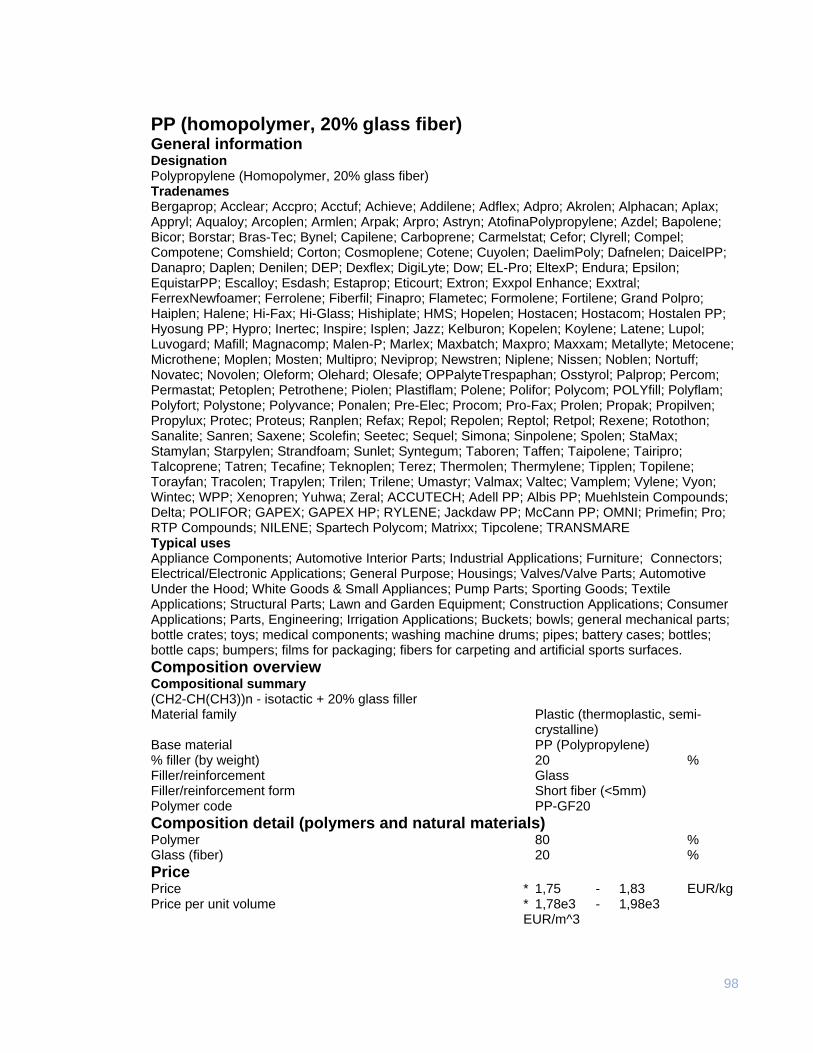
98
PP (homopolymer, 20% glass fiber) General information Designation Polypropylene (Homopolymer, 20% glass fiber) Tradenames Bergaprop; Acclear; Accpro; Acctuf; Achieve; Addilene; Adflex; Adpro; Akrolen; Alphacan; Aplax; Appryl; Aqualoy; Arcoplen; Armlen; Arpak; Arpro; Astryn; AtofinaPolypropylene; Azdel; Bapolene; Bicor; Borstar; Bras-Tec; Bynel; Capilene; Carboprene; Carmelstat; Cefor; Clyrell; Compel; Compotene; Comshield; Corton; Cosmoplene; Cotene; Cuyolen; DaelimPoly; Dafnelen; DaicelPP; Danapro; Daplen; Denilen; DEP; Dexflex; DigiLyte; Dow; EL-Pro; EltexP; Endura; Epsilon; EquistarPP; Escalloy; Esdash; Estaprop; Eticourt; Extron; Exxpol Enhance; Exxtral; FerrexNewfoamer; Ferrolene; Fiberfil; Finapro; Flametec; Formolene; Fortilene; Grand Polpro; Haiplen; Halene; Hi-Fax; Hi-Glass; Hishiplate; HMS; Hopelen; Hostacen; Hostacom; Hostalen PP; Hyosung PP; Hypro; Inertec; Inspire; Isplen; Jazz; Kelburon; Kopelen; Koylene; Latene; Lupol; Luvogard; Mafill; Magnacomp; Malen-P; Marlex; Maxbatch; Maxpro; Maxxam; Metallyte; Metocene; Microthene; Moplen; Mosten; Multipro; Neviprop; Newstren; Niplene; Nissen; Noblen; Nortuff; Novatec; Novolen; Oleform; Olehard; Olesafe; OPPalyteTrespaphan; Osstyrol; Palprop; Percom; Permastat; Petoplen; Petrothene; Piolen; Plastiflam; Polene; Polifor; Polycom; POLYfill; Polyflam; Polyfort; Polystone; Polyvance; Ponalen; Pre-Elec; Procom; Pro-Fax; Prolen; Propak; Propilven; Propylux; Protec; Proteus; Ranplen; Refax; Repol; Repolen; Reptol; Retpol; Rexene; Rotothon; Sanalite; Sanren; Saxene; Scolefin; Seetec; Sequel; Simona; Sinpolene; Spolen; StaMax; Stamylan; Starpylen; Strandfoam; Sunlet; Syntegum; Taboren; Taffen; Taipolene; Tairipro; Talcoprene; Tatren; Tecafine; Teknoplen; Terez; Thermolen; Thermylene; Tipplen; Topilene; Torayfan; Tracolen; Trapylen; Trilen; Trilene; Umastyr; Valmax; Valtec; Vamplem; Vylene; Vyon; Wintec; WPP; Xenopren; Yuhwa; Zeral; ACCUTECH; Adell PP; Albis PP; Muehlstein Compounds; Delta; POLIFOR; GAPEX; GAPEX HP; RYLENE; Jackdaw PP; McCann PP; OMNI; Primefin; Pro; RTP Compounds; NILENE; Spartech Polycom; Matrixx; Tipcolene; TRANSMARE Typical uses Appliance Components; Automotive Interior Parts; Industrial Applications; Furniture; Connectors; Electrical/Electronic Applications; General Purpose; Housings; Valves/Valve Parts; Automotive Under the Hood; White Goods & Small Appliances; Pump Parts; Sporting Goods; Textile Applications; Structural Parts; Lawn and Garden Equipment; Construction Applications; Consumer Applications; Parts, Engineering; Irrigation Applications; Buckets; bowls; general mechanical parts; bottle crates; toys; medical components; washing machine drums; pipes; battery cases; bottles; bottle caps; bumpers; films for packaging; fibers for carpeting and artificial sports surfaces.
Composition overview Compositional summary (CH2-CH(CH3))n - isotactic + 20% glass filler Material family Plastic (thermoplastic, semi-
crystalline) Base material PP (Polypropylene) % filler (by weight) 20 % Filler/reinforcement Glass Filler/reinforcement form Short fiber (<5mm) Polymer code PP-GF20
Composition detail (polymers and natural materials) Polymer 80 % Glass (fiber) 20 %
Price Price * 1,75 - 1,83 EUR/kg Price per unit volume * 1,78e3 - 1,98e3 EUR/m^3
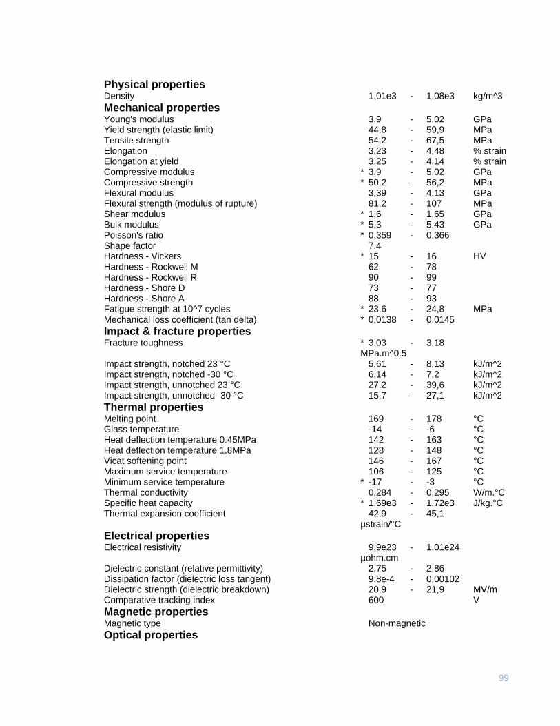
99
Physical properties Density 1,01e3 - 1,08e3 kg/m^3
Mechanical properties Young's modulus 3,9 - 5,02 GPa Yield strength (elastic limit) 44,8 - 59,9 MPa Tensile strength 54,2 - 67,5 MPa Elongation 3,23 - 4,48 % strain Elongation at yield 3,25 - 4,14 % strain Compressive modulus * 3,9 - 5,02 GPa Compressive strength * 50,2 - 56,2 MPa Flexural modulus 3,39 - 4,13 GPa Flexural strength (modulus of rupture) 81,2 - 107 MPa Shear modulus * 1,6 - 1,65 GPa Bulk modulus * 5,3 - 5,43 GPa Poisson's ratio * 0,359 - 0,366 Shape factor 7,4 Hardness - Vickers * 15 - 16 HV Hardness - Rockwell M 62 - 78 Hardness - Rockwell R 90 - 99 Hardness - Shore D 73 - 77 Hardness - Shore A 88 - 93 Fatigue strength at 10^7 cycles * 23,6 - 24,8 MPa Mechanical loss coefficient (tan delta) * 0,0138 - 0,0145
Impact & fracture properties Fracture toughness * 3,03 - 3,18 MPa.m^0.5 Impact strength, notched 23 °C 5,61 - 8,13 kJ/m^2 Impact strength, notched -30 °C 6,14 - 7,2 kJ/m^2 Impact strength, unnotched 23 °C 27,2 - 39,6 kJ/m^2 Impact strength, unnotched -30 °C 15,7 - 27,1 kJ/m^2
Thermal properties Melting point 169 - 178 °C Glass temperature -14 - -6 °C Heat deflection temperature 0.45MPa 142 - 163 °C Heat deflection temperature 1.8MPa 128 - 148 °C Vicat softening point 146 - 167 °C Maximum service temperature 106 - 125 °C Minimum service temperature * -17 - -3 °C Thermal conductivity 0,284 - 0,295 W/m.°C Specific heat capacity * 1,69e3 - 1,72e3 J/kg.°C Thermal expansion coefficient 42,9 - 45,1 µstrain/°C
Electrical properties Electrical resistivity 9,9e23 - 1,01e24 µohm.cm Dielectric constant (relative permittivity) 2,75 - 2,86 Dissipation factor (dielectric loss tangent) 9,8e-4 - 0,00102 Dielectric strength (dielectric breakdown) 20,9 - 21,9 MV/m Comparative tracking index 600 V
Magnetic properties Magnetic type Non-magnetic
Optical properties
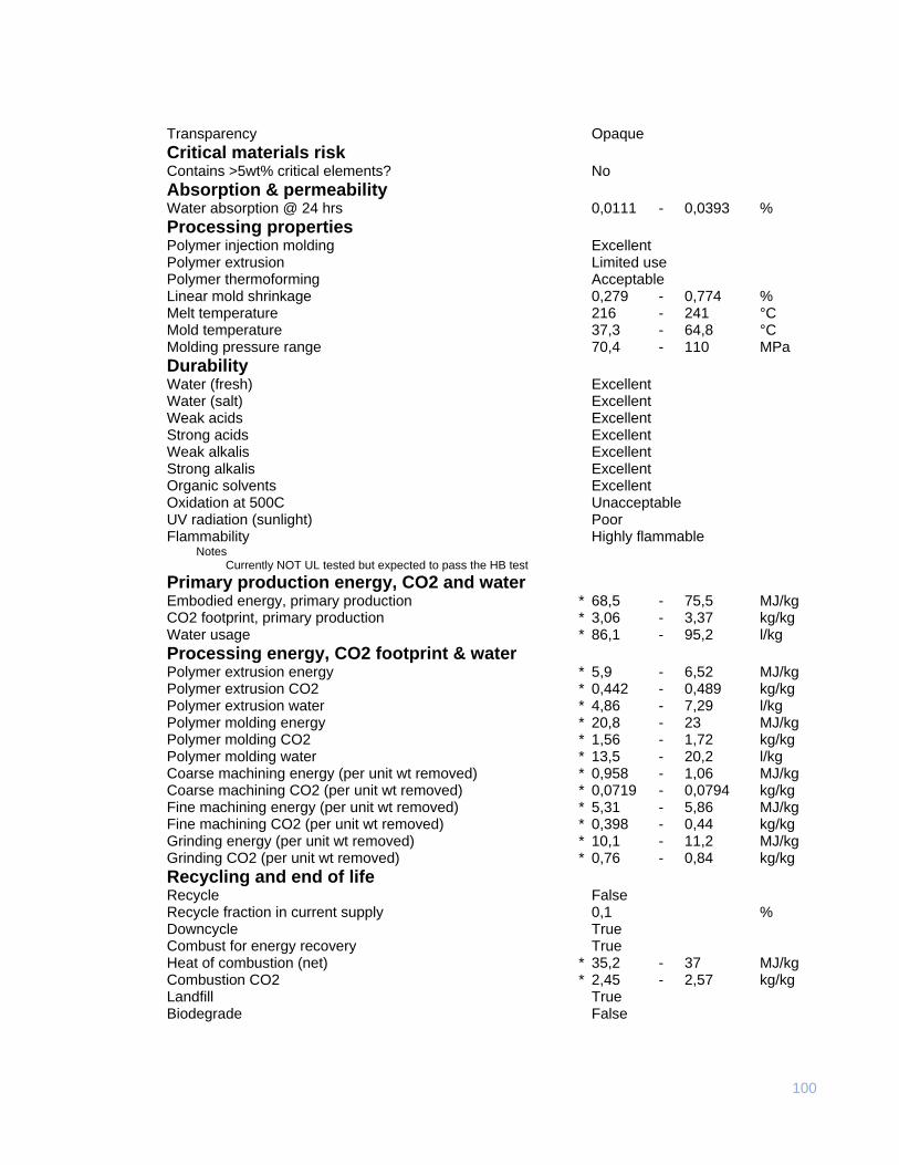
100
Transparency Opaque
Critical materials risk Contains >5wt% critical elements? No
Absorption & permeability Water absorption @ 24 hrs 0,0111 - 0,0393 %
Processing properties Polymer injection molding Excellent Polymer extrusion Limited use Polymer thermoforming Acceptable Linear mold shrinkage 0,279 - 0,774 % Melt temperature 216 - 241 °C Mold temperature 37,3 - 64,8 °C Molding pressure range 70,4 - 110 MPa
Durability Water (fresh) Excellent Water (salt) Excellent Weak acids Excellent Strong acids Excellent Weak alkalis Excellent Strong alkalis Excellent Organic solvents Excellent Oxidation at 500C Unacceptable UV radiation (sunlight) Poor Flammability Highly flammable
Notes Currently NOT UL tested but expected to pass the HB test
Primary production energy, CO2 and water Embodied energy, primary production * 68,5 - 75,5 MJ/kg CO2 footprint, primary production * 3,06 - 3,37 kg/kg Water usage * 86,1 - 95,2 l/kg
Processing energy, CO2 footprint & water Polymer extrusion energy * 5,9 - 6,52 MJ/kg Polymer extrusion CO2 * 0,442 - 0,489 kg/kg Polymer extrusion water * 4,86 - 7,29 l/kg Polymer molding energy * 20,8 - 23 MJ/kg Polymer molding CO2 * 1,56 - 1,72 kg/kg Polymer molding water * 13,5 - 20,2 l/kg Coarse machining energy (per unit wt removed) * 0,958 - 1,06 MJ/kg Coarse machining CO2 (per unit wt removed) * 0,0719 - 0,0794 kg/kg Fine machining energy (per unit wt removed) * 5,31 - 5,86 MJ/kg Fine machining CO2 (per unit wt removed) * 0,398 - 0,44 kg/kg Grinding energy (per unit wt removed) * 10,1 - 11,2 MJ/kg Grinding CO2 (per unit wt removed) * 0,76 - 0,84 kg/kg
Recycling and end of life Recycle False Recycle fraction in current supply 0,1 % Downcycle True Combust for energy recovery True Heat of combustion (net) * 35,2 - 37 MJ/kg Combustion CO2 * 2,45 - 2,57 kg/kg Landfill True Biodegrade False
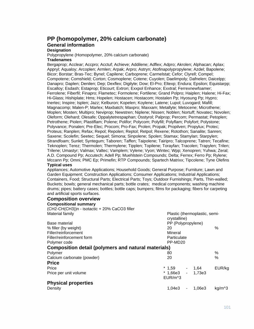
101
PP (homopolymer, 20% calcium carbonate) General information Designation Polypropylene (Homopolymer, 20% calcium carbonate) Tradenames Bergaprop; Acclear; Accpro; Acctuf; Achieve; Addilene; Adflex; Adpro; Akrolen; Alphacan; Aplax; Appryl; Aqualoy; Arcoplen; Armlen; Arpak; Arpro; Astryn; Atofinapolypropylene; Azdel; Bapolene; Bicor; Borstar; Bras-Tec; Bynel; Capilene; Carboprene; Carmelstat; Cefor; Clyrell; Compel; Compotene; Comshield; Corton; Cosmoplene; Cotene; Cuyolen; Daelimpoly; Dafnelen; Daicelpp; Danapro; Daplen; Denilen; Dep; Dexflex; Digilyte; Dow; El-Pro; Eltexp; Endura; Epsilon; Equistarpp; Escalloy; Esdash; Estaprop; Eticourt; Extron; Exxpol Enhance; Exxtral; Ferrexnewfoamer; Ferrolene; Fiberfil; Finapro; Flametec; Formolene; Fortilene; Grand Polpro; Haiplen; Halene; Hi-Fax; Hi-Glass; Hishiplate; Hms; Hopelen; Hostacen; Hostacom; Hostalen Pp; Hyosung Pp; Hypro; Inertec; Inspire; Isplen; Jazz; Kelburon; Kopelen; Koylene; Latene; Lupol; Luvogard; Mafill; Magnacomp; Malen-P; Marlex; Maxbatch; Maxpro; Maxxam; Metallyte; Metocene; Microthene; Moplen; Mosten; Multipro; Neviprop; Newstren; Niplene; Nissen; Noblen; Nortuff; Novatec; Novolen; Oleform; Olehard; Olesafe; Oppalytetrespaphan; Osstyrol; Palprop; Percom; Permastat; Petoplen; Petrothene; Piolen; Plastiflam; Polene; Polifor; Polycom; Polyfill; Polyflam; Polyfort; Polystone; Polyvance; Ponalen; Pre-Elec; Procom; Pro-Fax; Prolen; Propak; Propilven; Propylux; Protec; Proteus; Ranplen; Refax; Repol; Repolen; Reptol; Retpol; Rexene; Rotothon; Sanalite; Sanren; Saxene; Scolefin; Seetec; Sequel; Simona; Sinpolene; Spolen; Stamax; Stamylan; Starpylen; Strandfoam; Sunlet; Syntegum; Taboren; Taffen; Taipolene; Tairipro; Talcoprene; Tatren; Tecafine; Teknoplen; Terez; Thermolen; Thermylene; Tipplen; Topilene; Torayfan; Tracolen; Trapylen; Trilen; Trilene; Umastyr; Valmax; Valtec; Vamplem; Vylene; Vyon; Wintec; Wpp; Xenopren; Yuhwa; Zeral; A.D. Compound Pp; Accutech; Adell Pp; Muehlstein Compounds; Delta; Ferrex; Ferro Pp; Rylene; Mccann Pp; Omni; PMC Ep; Primefin; RTP Compounds; Spartech Matrixx; Tipcolene; Tyne Olefins Typical uses Appliances; Automotive Applications; Household Goods; General Purpose; Furniture; Lawn and Garden Equipment; Construction Applications; Consumer Applications; Industrial Applications; Containers, Food; Structural Parts; Electrical Parts; Toys; Outdoor Furnishings; Parts, Thin-walled; Buckets; bowls; general mechanical parts; bottle crates; medical components; washing machine drums; pipes; battery cases; bottles; bottle caps; bumpers; films for packaging; fibers for carpeting and artificial sports surfaces.
Composition overview Compositional summary (CH2-CH(CH3))n - isotactic + 20% CaCO3 filler Material family Plastic (thermoplastic, semi-
crystalline) Base material PP (Polypropylene) % filler (by weight) 20 % Filler/reinforcement Mineral Filler/reinforcement form Particulate Polymer code PP-MD20
Composition detail (polymers and natural materials) Polymer 80 % Calcium carbonate (powder) 20 %
Price Price * 1,59 - 1,64 EUR/kg Price per unit volume * 1,66e3 - 1,73e3 EUR/m^3
Physical properties Density 1,04e3 - 1,06e3 kg/m^3
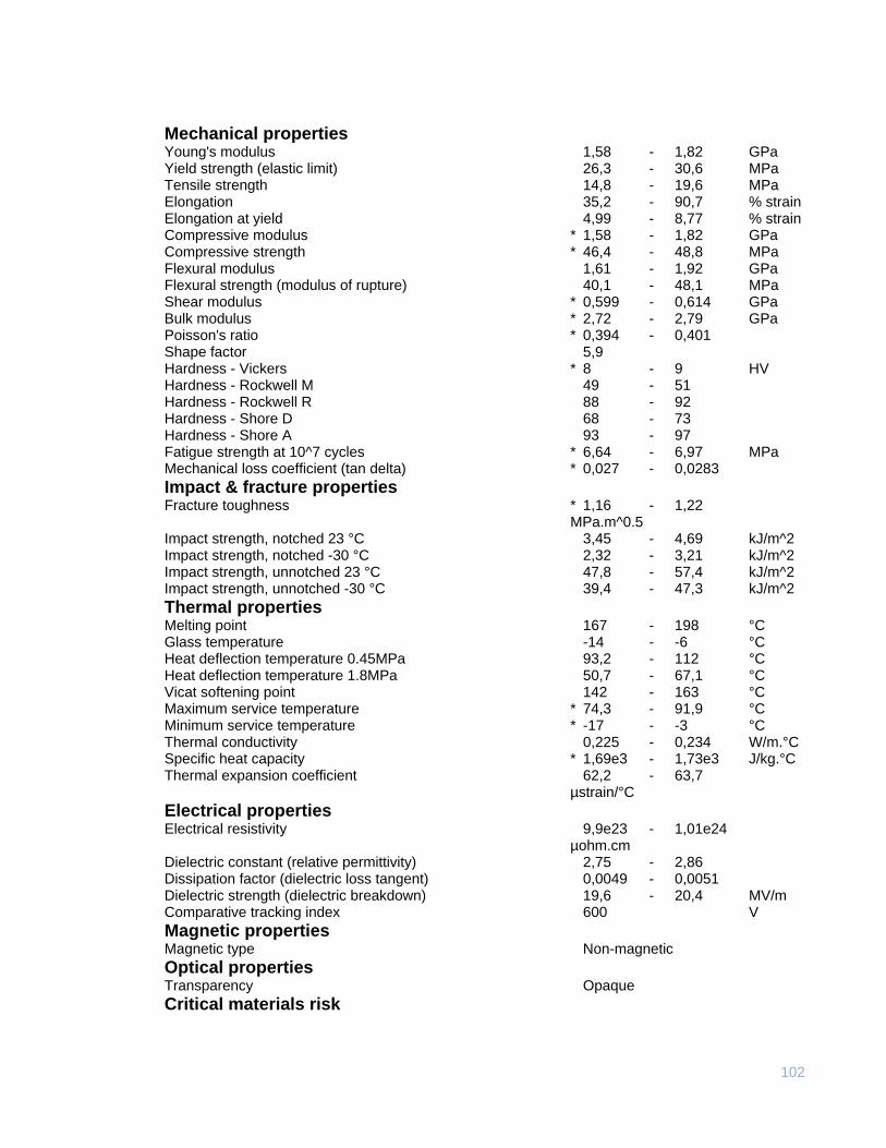
102
Mechanical properties Young's modulus 1,58 - 1,82 GPa Yield strength (elastic limit) 26,3 - 30,6 MPa Tensile strength 14,8 - 19,6 MPa Elongation 35,2 - 90,7 % strain Elongation at yield 4,99 - 8,77 % strain Compressive modulus * 1,58 - 1,82 GPa Compressive strength * 46,4 - 48,8 MPa Flexural modulus 1,61 - 1,92 GPa Flexural strength (modulus of rupture) 40,1 - 48,1 MPa Shear modulus * 0,599 - 0,614 GPa Bulk modulus * 2,72 - 2,79 GPa Poisson's ratio * 0,394 - 0,401 Shape factor 5,9 Hardness - Vickers * 8 - 9 HV Hardness - Rockwell M 49 - 51 Hardness - Rockwell R 88 - 92 Hardness - Shore D 68 - 73 Hardness - Shore A 93 - 97 Fatigue strength at 10^7 cycles * 6,64 - 6,97 MPa Mechanical loss coefficient (tan delta) * 0,027 - 0,0283
Impact & fracture properties Fracture toughness * 1,16 - 1,22 MPa.m^0.5 Impact strength, notched 23 °C 3,45 - 4,69 kJ/m^2 Impact strength, notched -30 °C 2,32 - 3,21 kJ/m^2 Impact strength, unnotched 23 °C 47,8 - 57,4 kJ/m^2 Impact strength, unnotched -30 °C 39,4 - 47,3 kJ/m^2
Thermal properties Melting point 167 - 198 °C Glass temperature -14 - -6 °C Heat deflection temperature 0.45MPa 93,2 - 112 °C Heat deflection temperature 1.8MPa 50,7 - 67,1 °C Vicat softening point 142 - 163 °C Maximum service temperature * 74,3 - 91,9 °C Minimum service temperature * -17 - -3 °C Thermal conductivity 0,225 - 0,234 W/m.°C Specific heat capacity * 1,69e3 - 1,73e3 J/kg.°C Thermal expansion coefficient 62,2 - 63,7 µstrain/°C
Electrical properties Electrical resistivity 9,9e23 - 1,01e24 µohm.cm Dielectric constant (relative permittivity) 2,75 - 2,86 Dissipation factor (dielectric loss tangent) 0,0049 - 0,0051 Dielectric strength (dielectric breakdown) 19,6 - 20,4 MV/m Comparative tracking index 600 V
Magnetic properties Magnetic type Non-magnetic
Optical properties Transparency Opaque
Critical materials risk
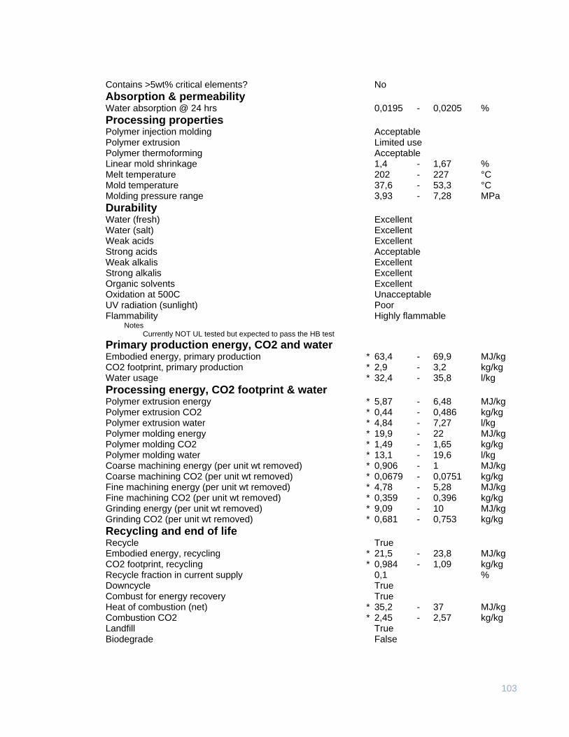
103
Contains >5wt% critical elements? No
Absorption & permeability Water absorption @ 24 hrs 0,0195 - 0,0205 %
Processing properties Polymer injection molding Acceptable Polymer extrusion Limited use Polymer thermoforming Acceptable Linear mold shrinkage 1,4 - 1,67 % Melt temperature 202 - 227 °C Mold temperature 37,6 - 53,3 °C Molding pressure range 3,93 - 7,28 MPa
Durability Water (fresh) Excellent Water (salt) Excellent Weak acids Excellent Strong acids Acceptable Weak alkalis Excellent Strong alkalis Excellent Organic solvents Excellent Oxidation at 500C Unacceptable UV radiation (sunlight) Poor Flammability Highly flammable
Notes Currently NOT UL tested but expected to pass the HB test
Primary production energy, CO2 and water Embodied energy, primary production * 63,4 - 69,9 MJ/kg CO2 footprint, primary production * 2,9 - 3,2 kg/kg Water usage * 32,4 - 35,8 l/kg
Processing energy, CO2 footprint & water Polymer extrusion energy * 5,87 - 6,48 MJ/kg Polymer extrusion CO2 * 0,44 - 0,486 kg/kg Polymer extrusion water * 4,84 - 7,27 l/kg Polymer molding energy * 19,9 - 22 MJ/kg Polymer molding CO2 * 1,49 - 1,65 kg/kg Polymer molding water * 13,1 - 19,6 l/kg Coarse machining energy (per unit wt removed) * 0,906 - 1 MJ/kg Coarse machining CO2 (per unit wt removed) * 0,0679 - 0,0751 kg/kg Fine machining energy (per unit wt removed) * 4,78 - 5,28 MJ/kg Fine machining CO2 (per unit wt removed) * 0,359 - 0,396 kg/kg Grinding energy (per unit wt removed) * 9,09 - 10 MJ/kg Grinding CO2 (per unit wt removed) * 0,681 - 0,753 kg/kg
Recycling and end of life Recycle True Embodied energy, recycling * 21,5 - 23,8 MJ/kg CO2 footprint, recycling * 0,984 - 1,09 kg/kg Recycle fraction in current supply 0,1 % Downcycle True Combust for energy recovery True Heat of combustion (net) * 35,2 - 37 MJ/kg Combustion CO2 * 2,45 - 2,57 kg/kg Landfill True Biodegrade False