
Corso di Percezione Robotica (PRo) C. Modulo di...
68
Corso di Percezione Robotica (PRo) Corso di Percezione Robotica (PRo) C. Modulo di Percezione C. Modulo di Percezione C. Modulo di Percezione C. Modulo di Percezione Fondamenti di visione artificiale retinica Cecilia Laschi ARTS Lab, Scuola Superiore Sant’Anna [email protected] 050-883486
Transcript of Corso di Percezione Robotica (PRo) C. Modulo di...
Corso di Percezione Robotica (PRo)Corso di Percezione Robotica (PRo)
C. Modulo di Percezione C. Modulo di Percezione C. Modulo di Percezione C. Modulo di Percezione
Fondamenti di visione
artificiale retinica
Cecilia Laschi
ARTS Lab, Scuola Superiore Sant’Anna
050-883486
Sommario della lezioneSommario della lezione
� Principi di base della visione retinica
� Alcune proprietà delle immagini retiniche
� Le relazioni matematiche tra immagini retiniche e cartesianeretiniche e cartesiane
� La foveazione
� Una testa robotica antropomorfa
� Esempi di applicazione in roboticaRiferimenti bibliografici:G. Sandini, G. Metta, “Retina- like sensors: motivations, technology and applications”. in Sensors and Sensing in Biology and Engineering. T.W. Secomb, F. Barth, and P. Humphrey, Editors. Springer-Verlag. 2002.
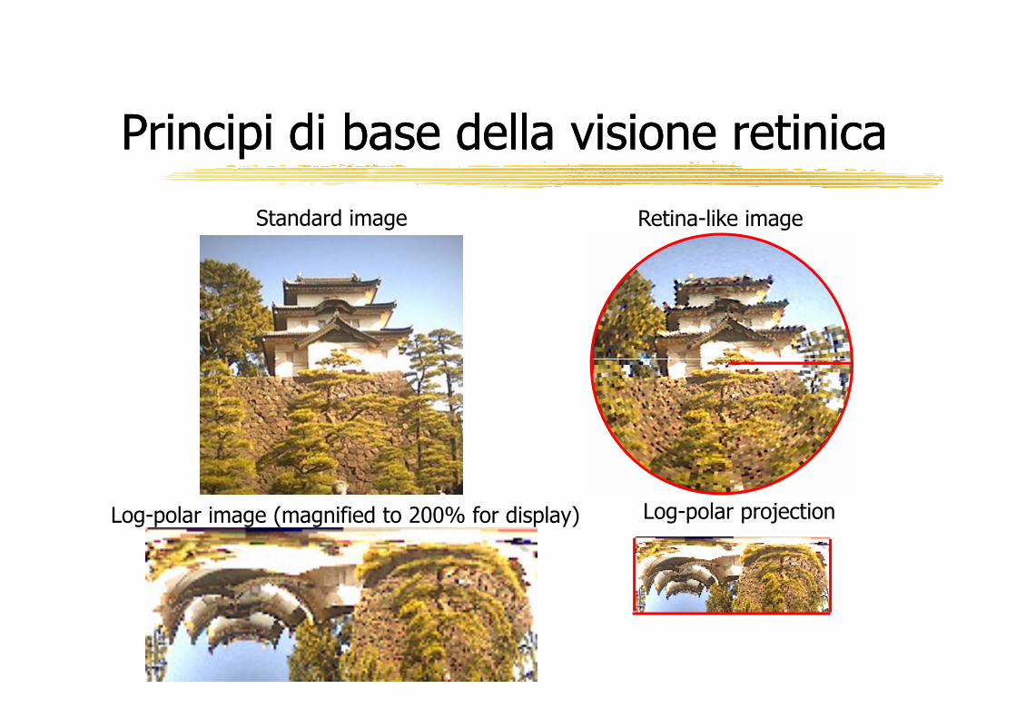
Principi di base della visione retinicaPrincipi di base della visione retinica
Standard image Retina-like image
Log-polar projectionLog-polar image (magnified to 200% for display)

Costruzione di un’immagine retinicaCostruzione di un’immagine retinica
Immagine cartesiana tradizionale
Divisione in circonferenze e spicchi
Calcolo del valore medio di un settore
http://www.retinica.com/
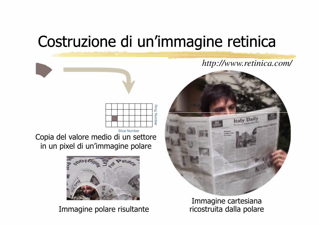
Costruzione di un’immagine retinicaCostruzione di un’immagine retinicahttp://www.retinica.com/
Copia del valore medio di un settore in un pixel di un’immagine polare
Immagine polare risultanteImmagine cartesiana ricostruita dalla polare
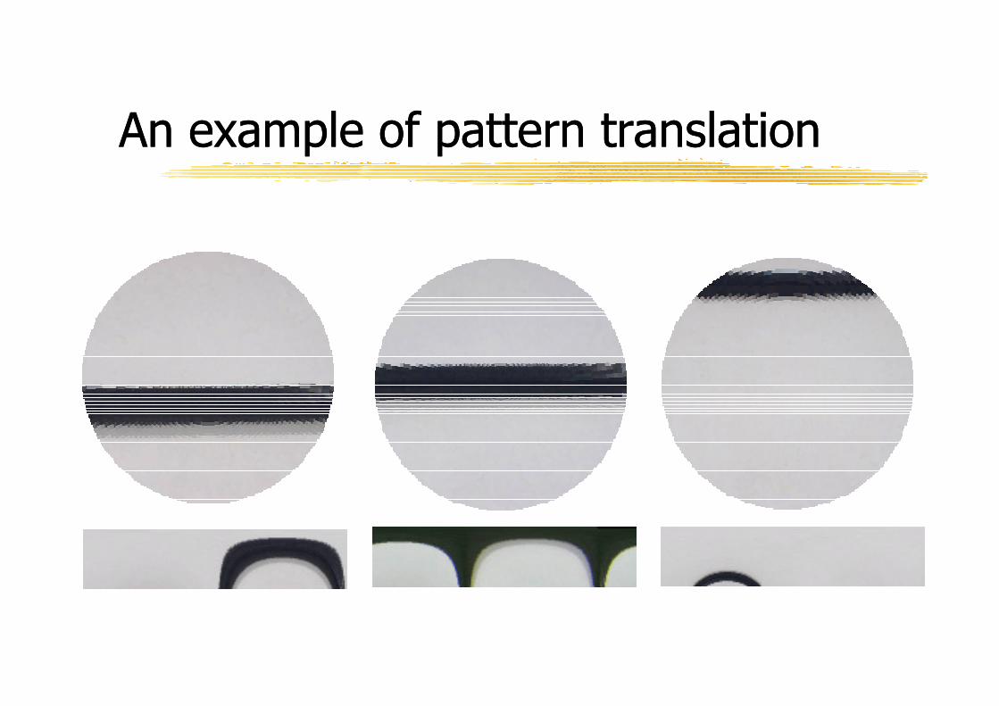
An example of pattern translation An example of pattern translation
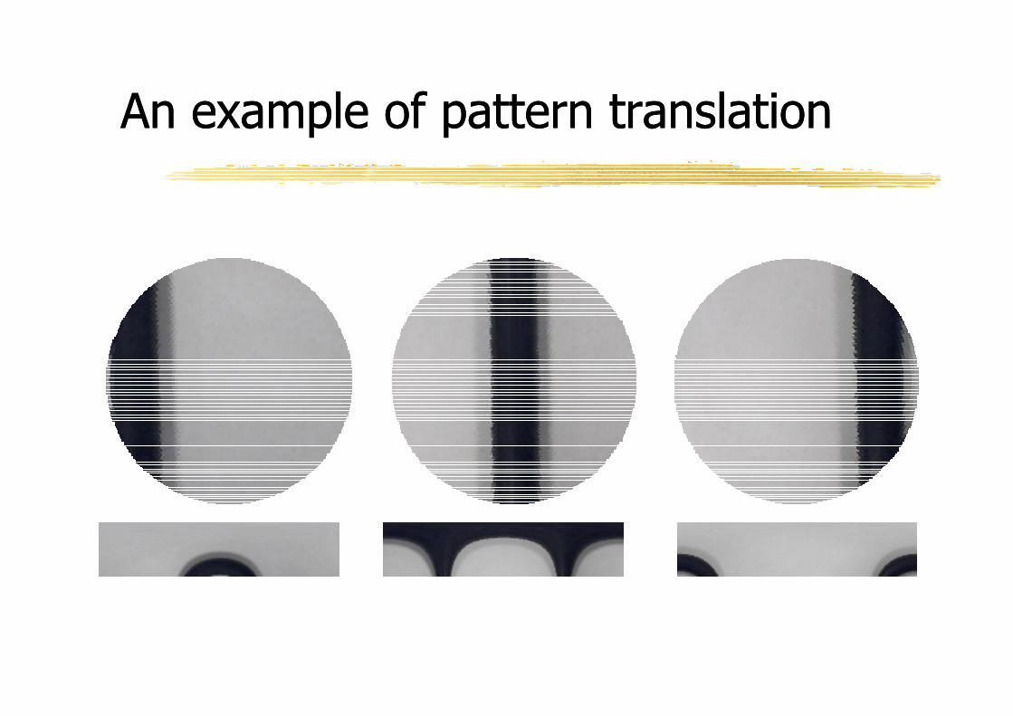
An example of pattern translation An example of pattern translation

An example of simulated foveationAn example of simulated foveation
Object detection in the periphery
Object foveation Foveation of a point of interest
(edge)
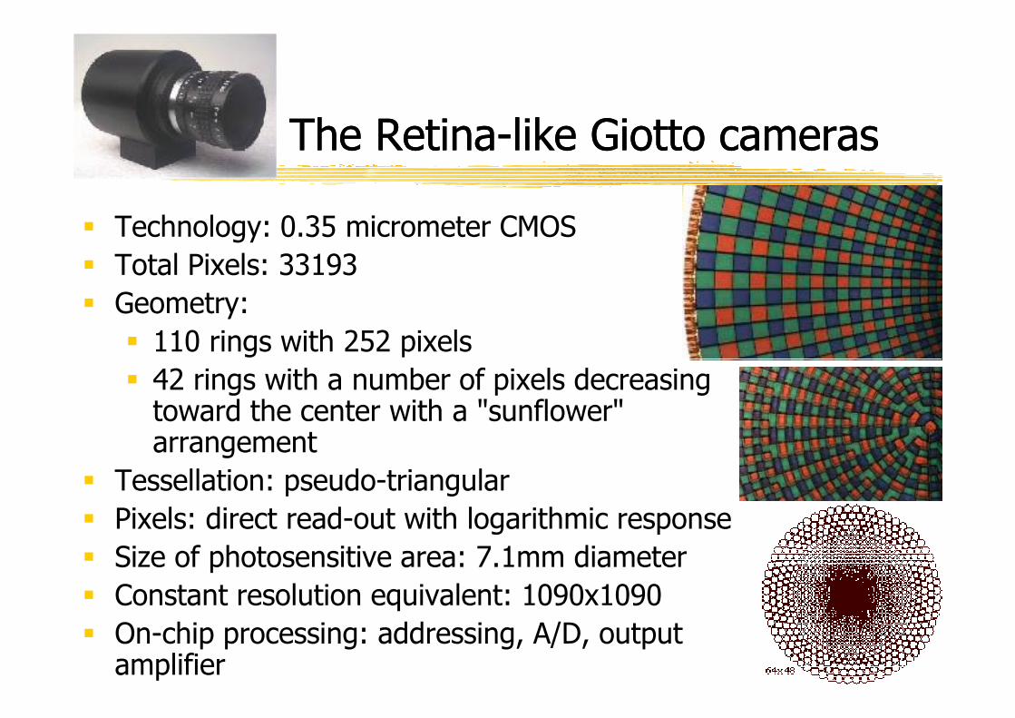
The RetinaThe Retina--like Giotto cameraslike Giotto cameras
� Technology: 0.35 micrometer CMOS
� Total Pixels: 33193
� Geometry:
� 110 rings with 252 pixels
� 42 rings with a number of pixels decreasing toward the center with a "sunflower" arrangement
� Tessellation: pseudo-triangular
� Pixels: direct read-out with logarithmic response
� Size of photosensitive area: 7.1mm diameter
� Constant resolution equivalent: 1090x1090
� On-chip processing: addressing, A/D, output amplifier
( ) ( )( ) ( )
( ) ( )
2 2 2 21 12 2
2 2 2 21 12 2
1 log 1 if
( , )
if
F F x y x y F
x yx y x y F
λ λ λ
ρ
− + − − + − + + > −
= + + + < −
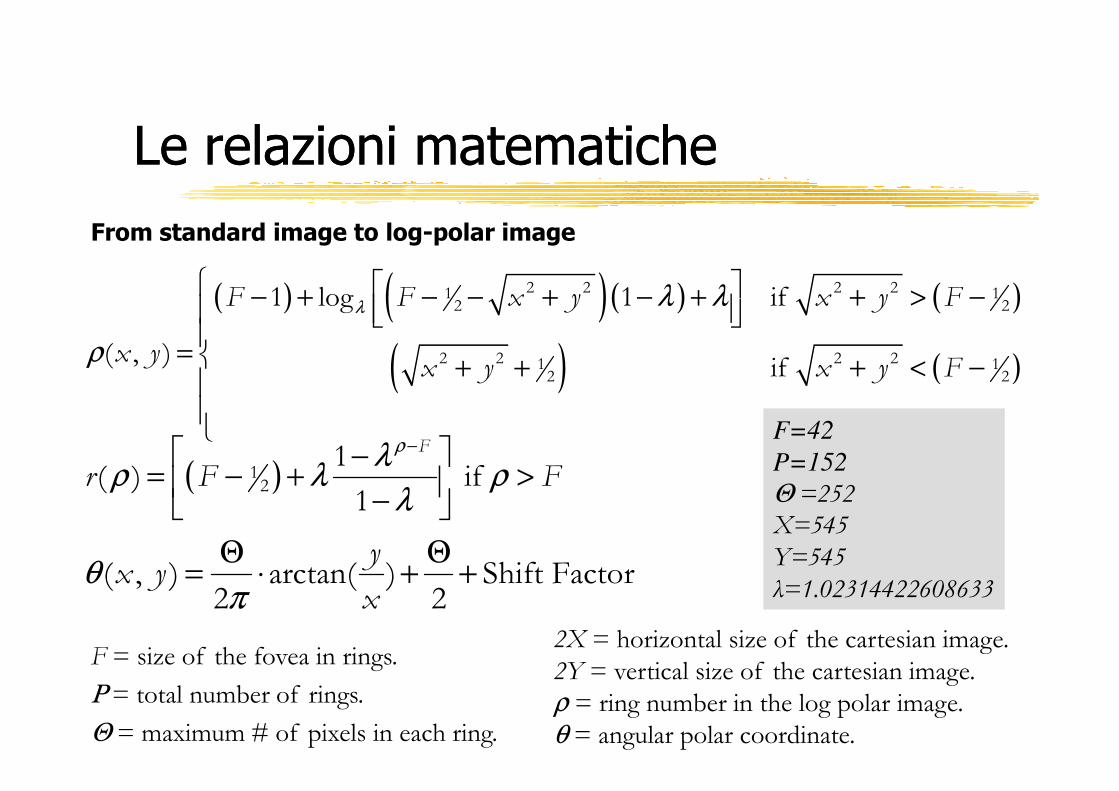
From standard image to log-polar image
Le relazioni matematicheLe relazioni matematiche
( )
( , ) arctan( ) Shift Factor2 2
yx y
xθ
π
Θ Θ= ⋅ + +
( )12
1( ) if
1
F
r F Fρλ
ρ λ ρλ
− −= − + >
−
2X = horizontal size of the cartesian image.
2Y = vertical size of the cartesian image.
ρ = ring number in the log polar image.θ = angular polar coordinate.
F = size of the fovea in rings.
Ρ = total number of rings.
Θ = maximum # of pixels in each ring.
F=42
P=152
Θ =252X=545
Y=545
λ=1.02314422608633
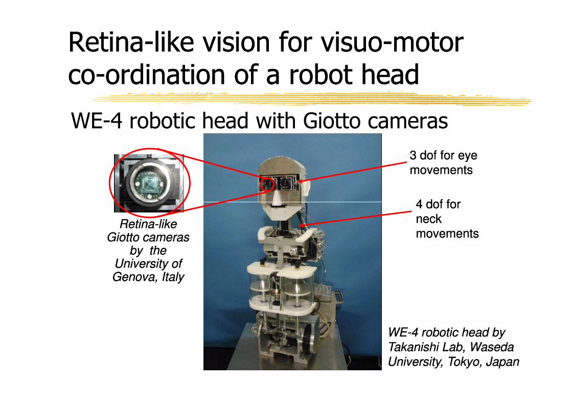
RetinaRetina--like vision for visuolike vision for visuo--motor motor coco--ordination of a robot head ordination of a robot head
WE-4 robotic head with Giotto cameras
4 dof for 4 dof for
3 dof for eye 3 dof for eye
movementsmovements
WEWE--4 robotic head by 4 robotic head by
Takanishi Lab, Waseda Takanishi Lab, Waseda
University, Tokyo, JapanUniversity, Tokyo, Japan
RetinaRetina--like like Giotto cameras Giotto cameras
by the by the University of University of Genova, ItalyGenova, Italy
4 dof for 4 dof for
neck neck
movementsmovements
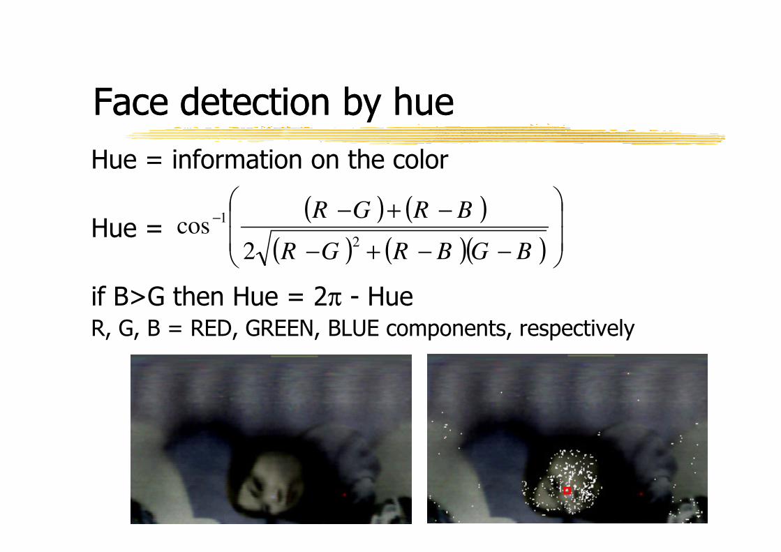
Face detection by hueFace detection by hue
Hue = information on the color
Hue =( ) ( )
( ) ( )( )
−−+−
−+−−
BGBRGR
BRGR
2
1
2cos
if B>G then Hue = 2π - HueR, G, B = RED, GREEN, BLUE components, respectively
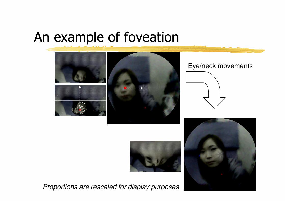
An example of foveationAn example of foveation
Eye/neck movements
Proportions are rescaled for display purposes
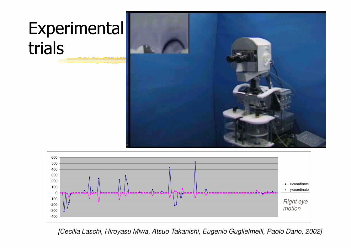
Experimental Experimental trialstrials
-400
-300
-200
-100
0
100
200
300
400
500
600
x coordinate
y coordinate
Right eye motion
[Cecilia Laschi, Hiroyasu Miwa, Atsuo Takanishi, Eugenio Guglielmelli, Paolo Dario, 2002]
Example of design and development of Example of design and development of a humana human--like robotic headlike robotic head
The ARTS humanoid robot
head
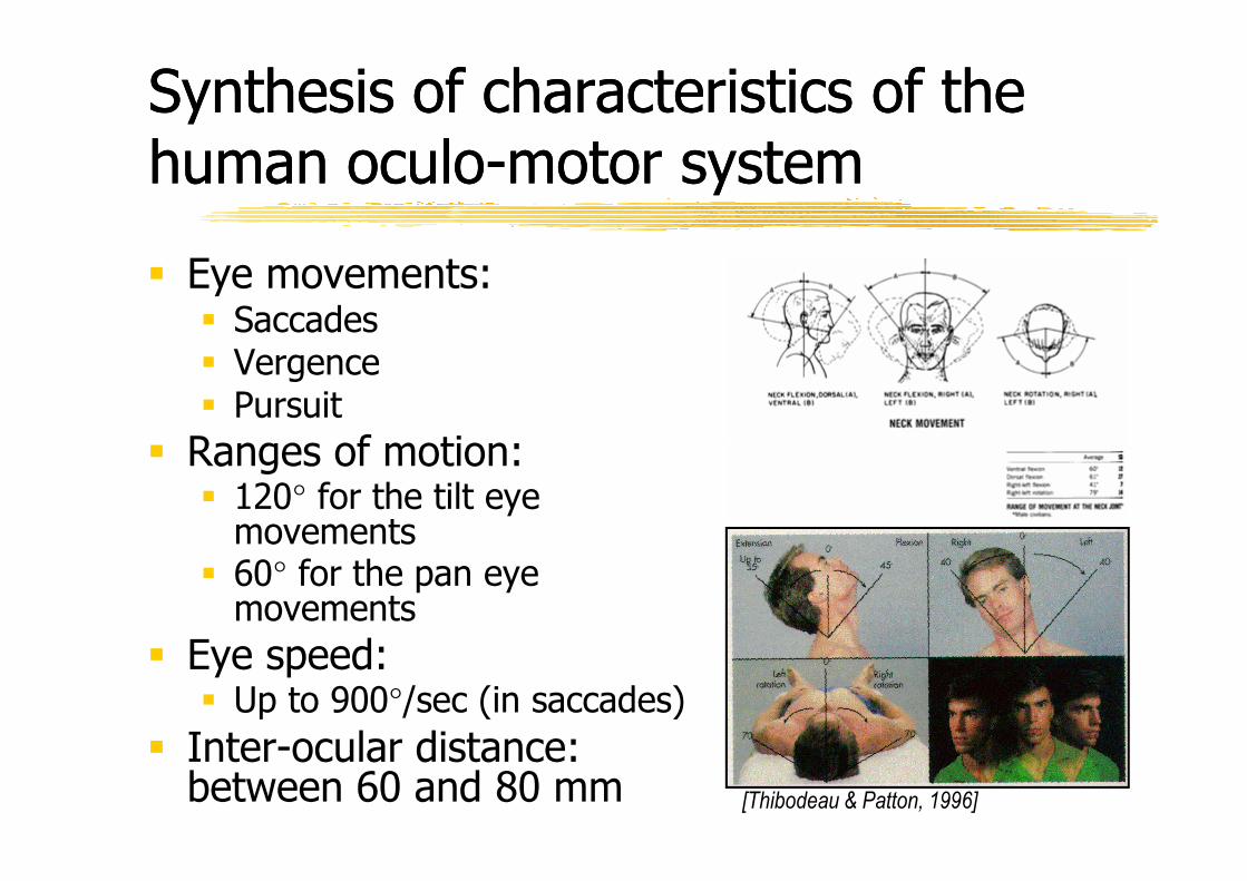
Synthesis of characteristics of the Synthesis of characteristics of the human oculohuman oculo--motor systemmotor system
� Eye movements:� Saccades� Vergence� Pursuit
� Ranges of motion:
60° 61°41° 41°
79° 79°
� Ranges of motion: � 120° for the tilt eye
movements� 60° for the pan eye
movements
� Eye speed: � Up to 900°/sec (in saccades)
� Inter-ocular distance: between 60 and 80 mm
[Hamill et al., 1995]
[Thibodeau & Patton, 1996]
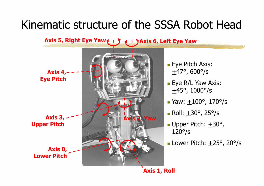
Kinematic structure of the SSSA Robot HeadKinematic structure of the SSSA Robot Head
Axis 4, Eye Pitch
Axis 5, Right Eye Yaw Axis 6, Left Eye Yaw
� Eye Pitch Axis: +47°, 600°/s
� Eye R/L Yaw Axis: +45°, 1000°/s
Axis 0, Lower Pitch
Axis 3, Upper Pitch
Axis 1, Roll
Axis 2, Yaw
+45°, 1000°/s
� Yaw: +100°, 170°/s
� Roll: +30°, 25°/s
� Upper Pitch: +30°,120°/s
� Lower Pitch: +25°, 20°/s
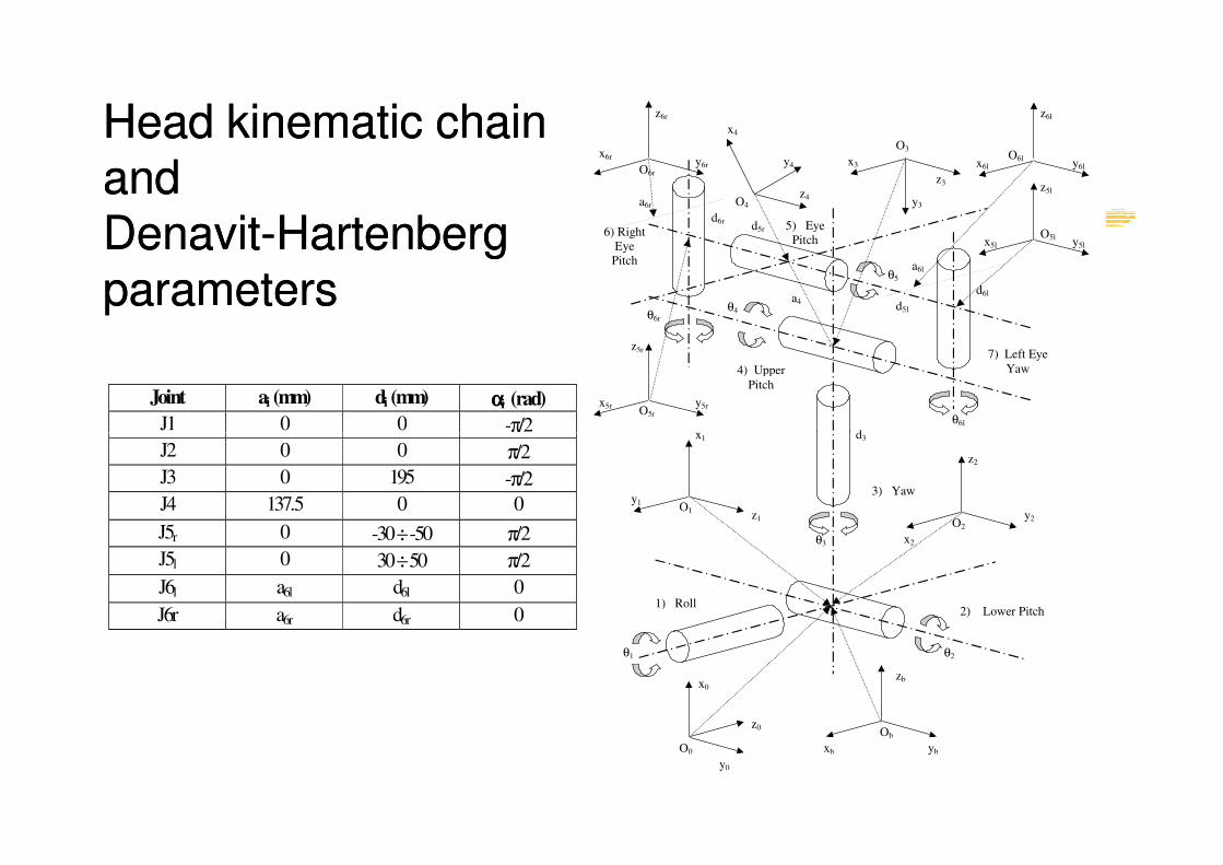
Head kinematic chainHead kinematic chainandandDenavitDenavit--Hartenberg Hartenberg
parametersparameters
Joint ai (mm) di (mm) ααααi (rad) J1 0 0 -π/2
a6r
θ5 a6l
d6r
d6l
y6l O6l
x6l
z6l
z3
y6r
x6r
z6r
O6r
6) Right
Eye
Pitch
d5l
d5r
a4
d
θ6l
θ6r θ4
z5r
y5r x5r O5r
y5l
z5l
x5l
O5l
O4
z4
y4
x4
y3
5) Eye
Pitch
x3
O3
x
4) Upper
Pitch
7) Left Eye
Yaw
J1 0 0 -π/2
J2 0 0 π/2
J3 0 195 -π/2
J4 137.5 0 0
J5r 0 -30 ÷ -50 π/2
J5l 0 30 ÷ 50 π/2
J6l a6l d6l 0
J6r a6r d6r 0
Ob
d3
θ3
θ2 θ1
O2
x2
z2
O1
O0
z1
y1
x1
x0
1) Roll
2) Lower Pitch
3) Yaw
xb yb
zb
z0
y0
y2
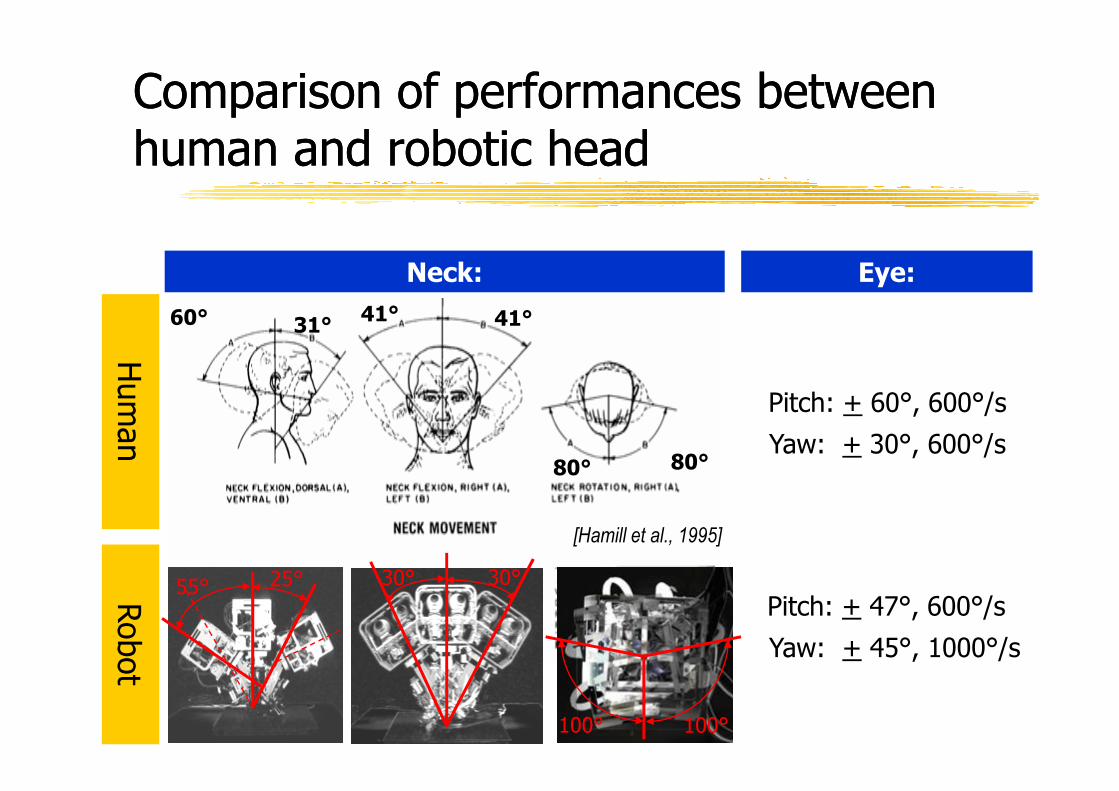
Comparison of performances between Comparison of performances between human and robotic headhuman and robotic head
Pitch: + 60°, 600°/s
Hum
an
Neck:
60° 31°41° 41°
Eye:
Pitch: + 60°, 600°/s
Yaw: + 30°, 600°/s
Hum
an
Robot
[Hamill et al., 1995]
Pitch: + 47°, 600°/s
Yaw: + 45°, 1000°/s
30° 30°25°55°
80° 80°
100° 100°
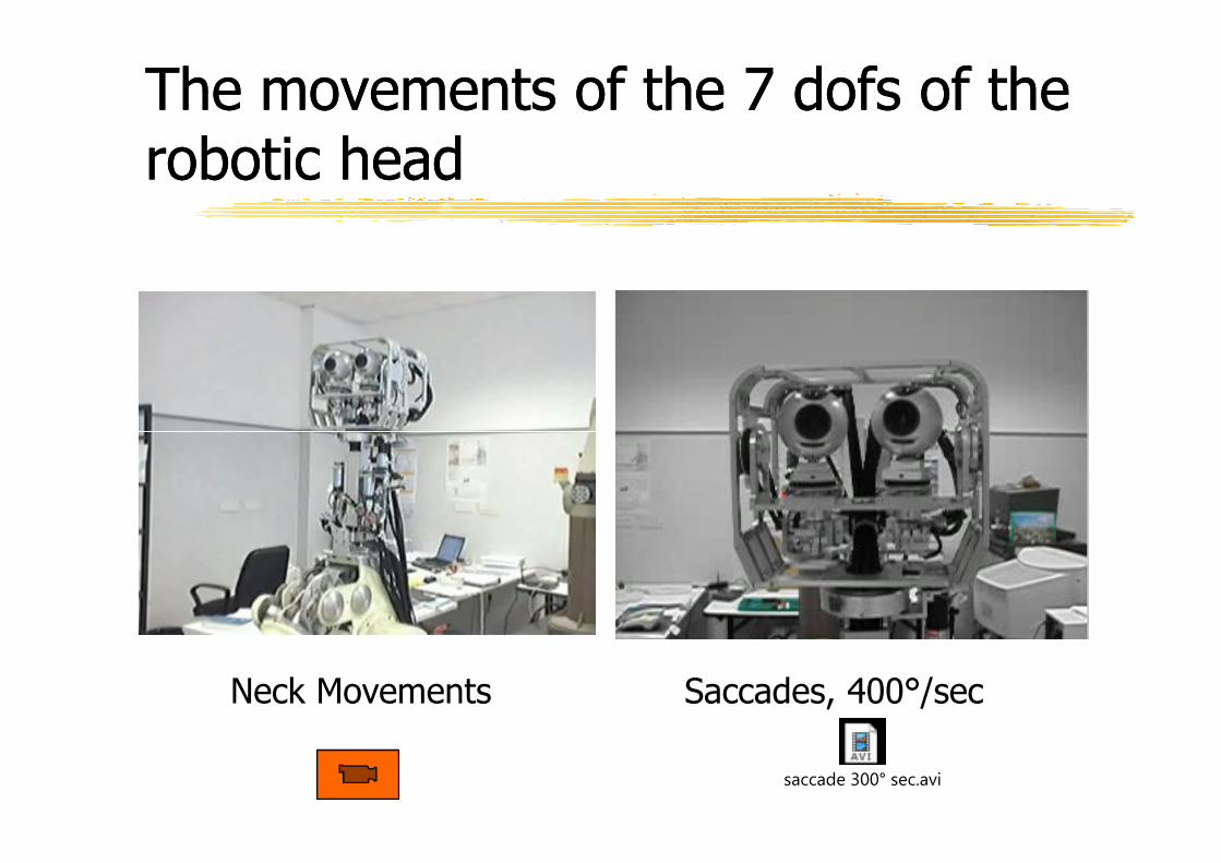
The movements of the 7 dofs of the The movements of the 7 dofs of the robotic headrobotic head
Neck Movements Saccades, 400°/sec
saccade 300° sec.avi
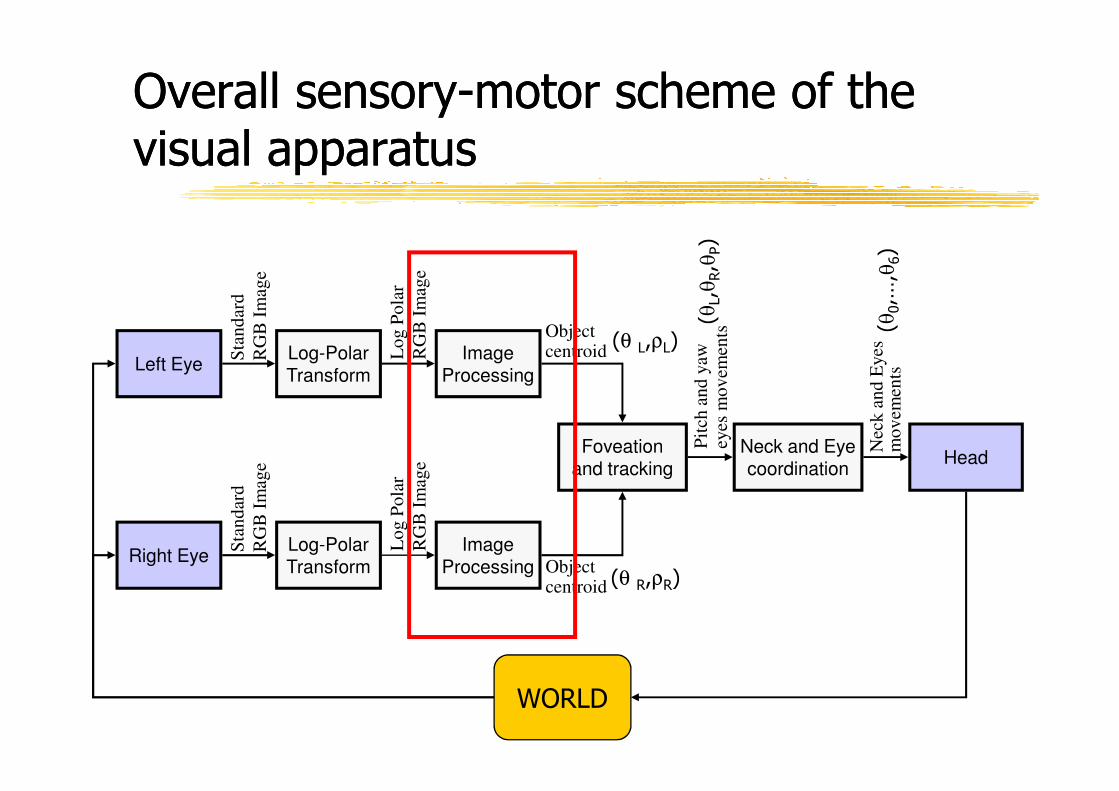
Left EyeLog-Polar Transform
Object centroid
Pit
ch a
nd
yaw
ey
es m
ov
emen
ts
Nec
k a
nd
Eyes
m
ov
emen
ts
Sta
nd
ard
RG
B I
mag
e
Lo
g P
ola
r
RG
B I
mag
e
Image Processing
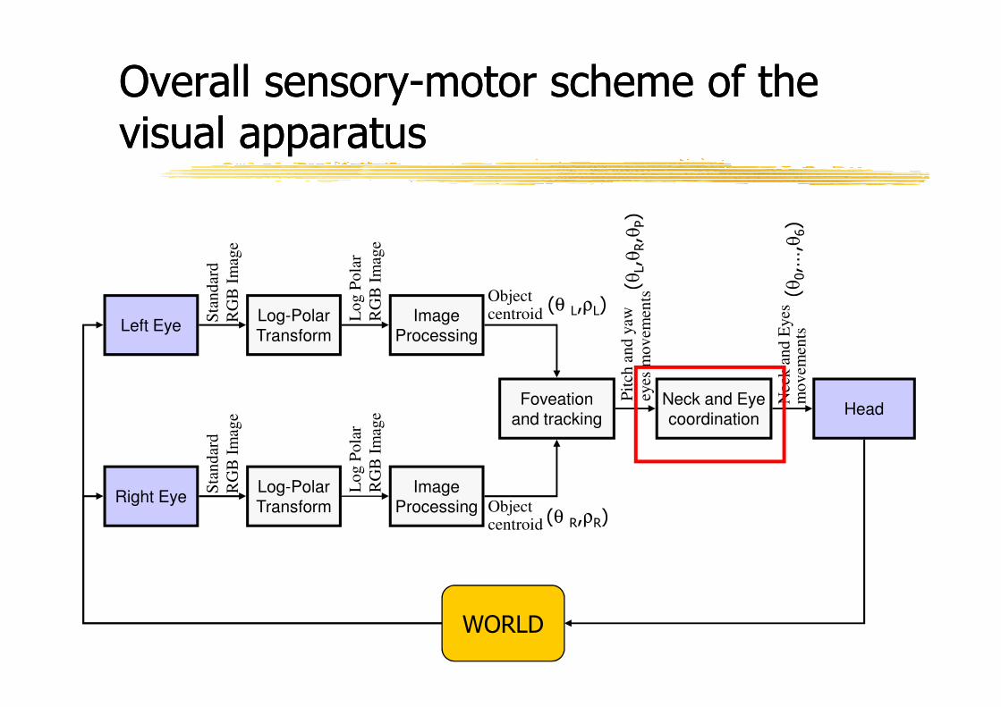
Overall sensoryOverall sensory--motor scheme of the motor scheme of the visual apparatusvisual apparatus
(θ L,ρL)
Right EyeLog-Polar Transform
Image Processing
Foveation and tracking
Neck and Eye coordination
Head
Sta
nd
ard
RG
B I
mag
e
Lo
g P
ola
r
RG
B I
mag
e
Object centroid
Pit
ch a
nd
yaw
ey
es m
ov
emen
ts
Nec
k a
nd
Eyes
m
ov
emen
ts
WORLD
(θ R,ρR)
Examples of algorithms developed for Examples of algorithms developed for retinaretina--like image processinglike image processing
� Acquiring standard image
� Creating log-polar image from standard image
� Creating retina-like image from log-polar image� Creating retina-like image from log-polar image
� Thresholding of image based on RGB and HUE
� Computation of the centroid of a thresholded area
� Edge detection
� Line detection
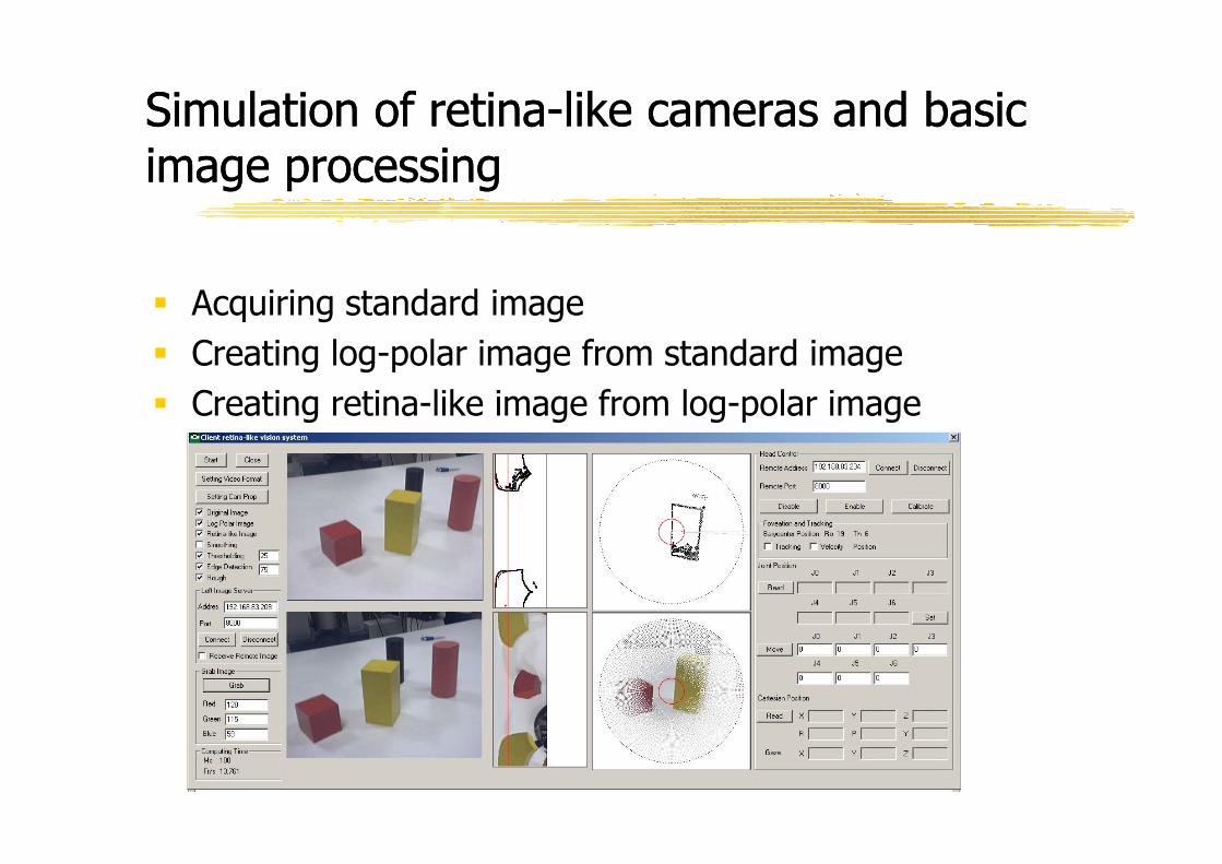
Simulation of retinaSimulation of retina--like cameras and basic like cameras and basic image processingimage processing
� Acquiring standard image
� Creating log-polar image from standard image
� Creating retina-like image from log-polar image
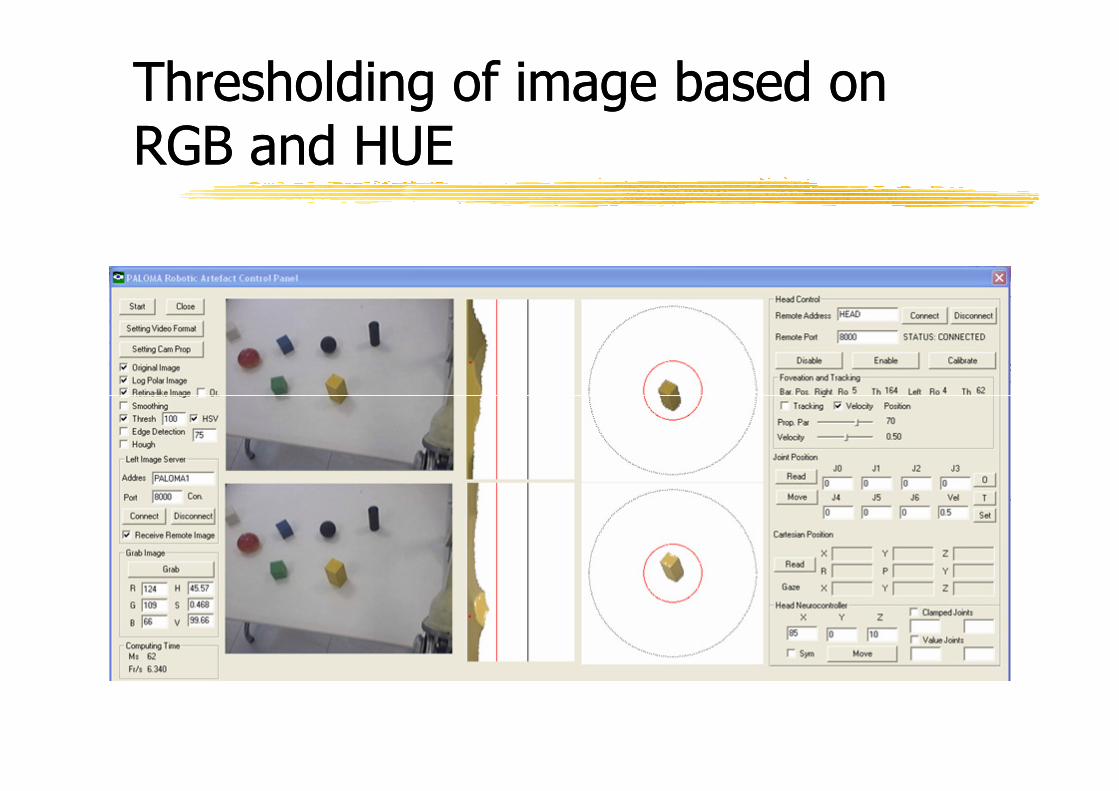
Thresholding of image based on Thresholding of image based on RGB and HUERGB and HUE
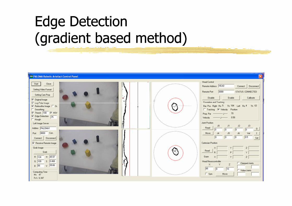
Edge Detection Edge Detection (gradient based method)(gradient based method)
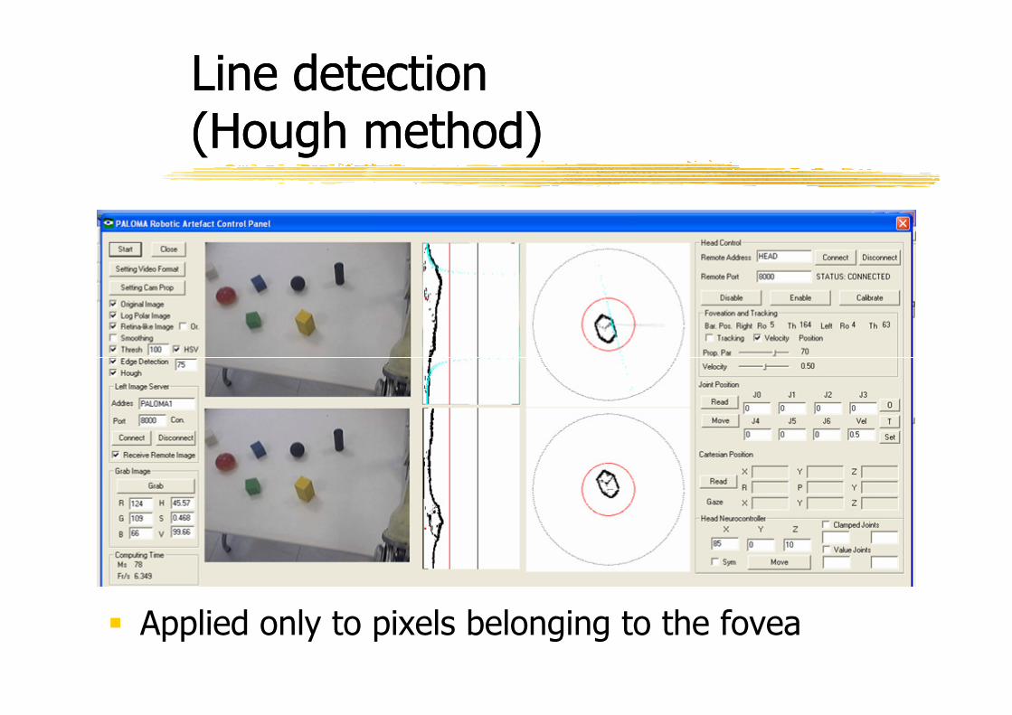
Line detectionLine detection(Hough method) (Hough method)
� Applied only to pixels belonging to the fovea
Line detectionLine detection

Preliminary activities on object recognition Preliminary activities on object recognition
Foveation and tracking of borders of object and reconstruction of the geometry of the object
Retina Like image
Log Polar Image
Edge of log polar image
Detected lines (Boundaries)
Boundary reconstruction based on eye positions

Left EyeLog-Polar Transform
Object centroid
Pit
ch a
nd
yaw
ey
es m
ov
emen
ts
Nec
k a
nd
Eyes
m
ov
emen
ts
Sta
nd
ard
RG
B I
mag
e
Lo
g P
ola
r
RG
B I
mag
e
Image Processing
Overall sensoryOverall sensory--motor scheme of the motor scheme of the visual apparatusvisual apparatus
(θ L,ρL)
Right EyeLog-Polar Transform
Image Processing
Foveation and tracking
Neck and Eye coordination
Head
Sta
nd
ard
RG
B I
mag
e
Lo
g P
ola
r
RG
B I
mag
e
Object centroid
Pit
ch a
nd
yaw
ey
es m
ov
emen
ts
Nec
k a
nd
Eyes
m
ov
emen
ts
WORLD
(θ R,ρR)
O O
Left Image Right Image
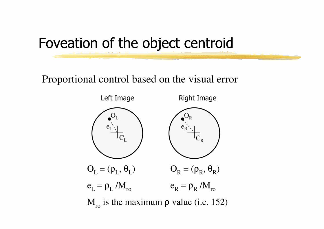
Foveation of the object centroidFoveation of the object centroid
Proportional control based on the visual error
CL CR
OL OR
eL eR
OL = (ρL, θL) OR = (ρR, θR)
eL = ρL /Mro eR = ρR /Mro
Mro is the maximum ρ value (i.e. 152)
eL
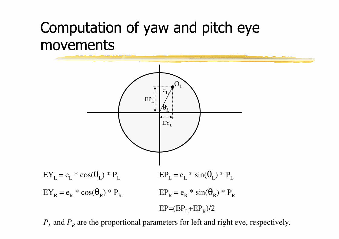
Computation of yaw and pitch eye Computation of yaw and pitch eye movementsmovements
θL
OL
EPL
EYL = eL * cos(θL) * PL EPL = eL * sin(θL) * PL
EYR = eR * cos(θR) * PR EPR = eR * sin(θR) * PR
EP=(EPL+EPR)/2
EYL
PL and PR are the proportional parameters for left and right eye, respectively.
Left EyeLog-Polar Transform
Object centroid
Pit
ch a
nd
yaw
ey
es m
ov
emen
ts
Nec
k a
nd
Eyes
m
ov
emen
ts
Sta
nd
ard
RG
B I
mag
e
Lo
g P
ola
r
RG
B I
mag
e
Image Processing
Overall sensoryOverall sensory--motor scheme of the motor scheme of the visual apparatusvisual apparatus
(θ L,ρL)
Right EyeLog-Polar Transform
Image Processing
Foveation and tracking
Neck and Eye coordination
Head
Sta
nd
ard
RG
B I
mag
e
Lo
g P
ola
r
RG
B I
mag
e
Object centroid
Pit
ch a
nd
yaw
ey
es m
ov
emen
ts
Nec
k a
nd
Eyes
m
ov
emen
ts
WORLD
(θ R,ρR)
EYL
Axis 2-Yaw
Axis 1-Lower Pitch
Axis 0-Roll
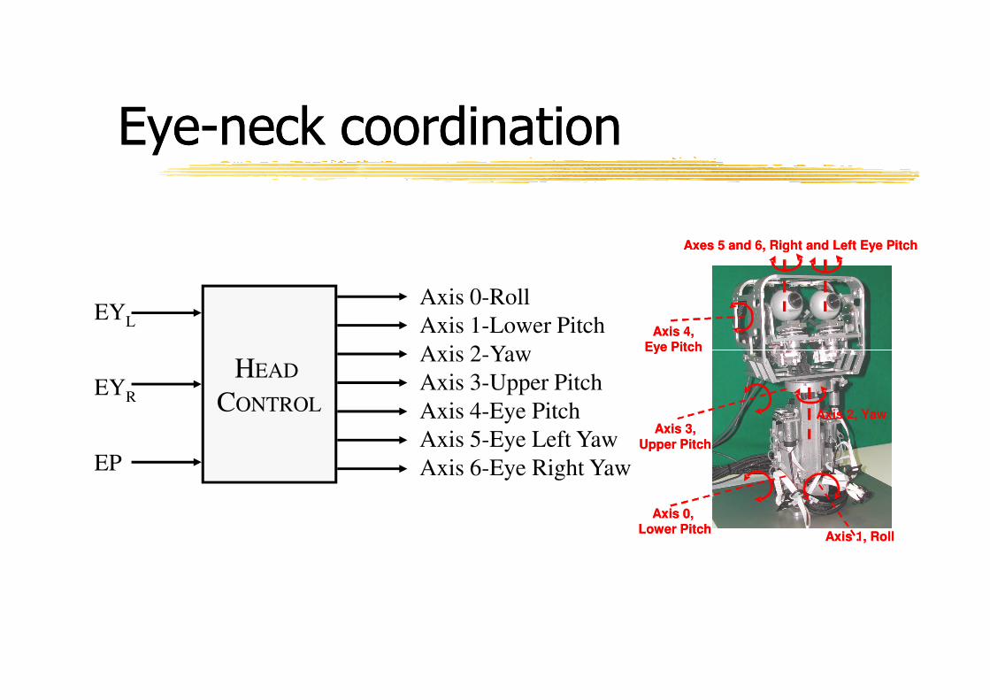
EyeEye--neck coordinationneck coordination
Axis 4,Eye Pitch
Axes 5 and 6, Right and Left Eye Pitch
Axis 4,Eye Pitch
Axes 5 and 6, Right and Left Eye Pitch
EYR
EP
HEAD
CONTROL
Axis 6-Eye Right Yaw
Axis 5-Eye Left Yaw
Axis 4-Eye Pitch
Axis 3-Upper Pitch
Axis 2-Yaw
Axis 1, Roll
Axis 2, Yaw
Eye Pitch
Axis 3,
Upper Pitch
Axis 0, Lower Pitch
Axis 1, Roll
Axis 2, Yaw
Eye Pitch
Axis 3,
Upper Pitch
Axis 0, Lower Pitch
Solution 1Solution 1
Distribution of the
movements between the
neck and eye DOF
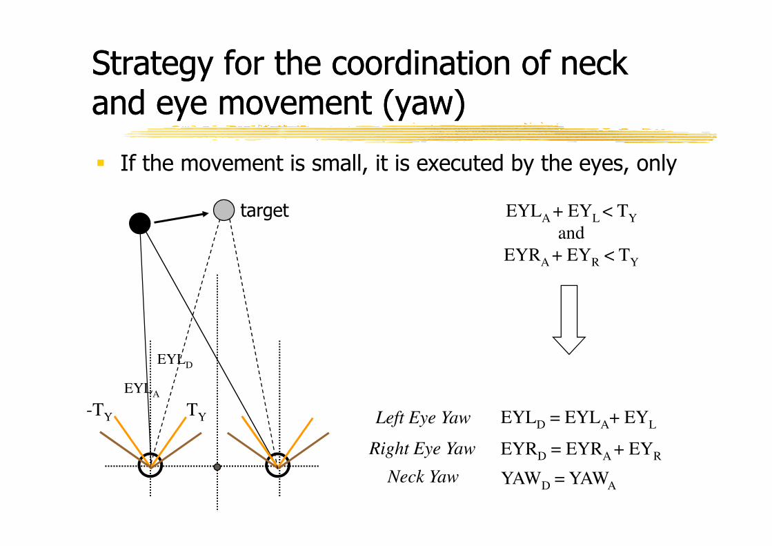
Strategy for the coordination of neck Strategy for the coordination of neck and eye movement (yaw)and eye movement (yaw)
target EYLA + EYL < TY
and
EYRA + EYR < TY
� If the movement is small, it is executed by the eyes, only
EYLD = EYLA+ EYL
EYRD = EYRA + EYR
YAWD = YAWA
TY
EYLD
Left Eye Yaw
EYLA
-TY
Right Eye Yaw
Neck Yaw
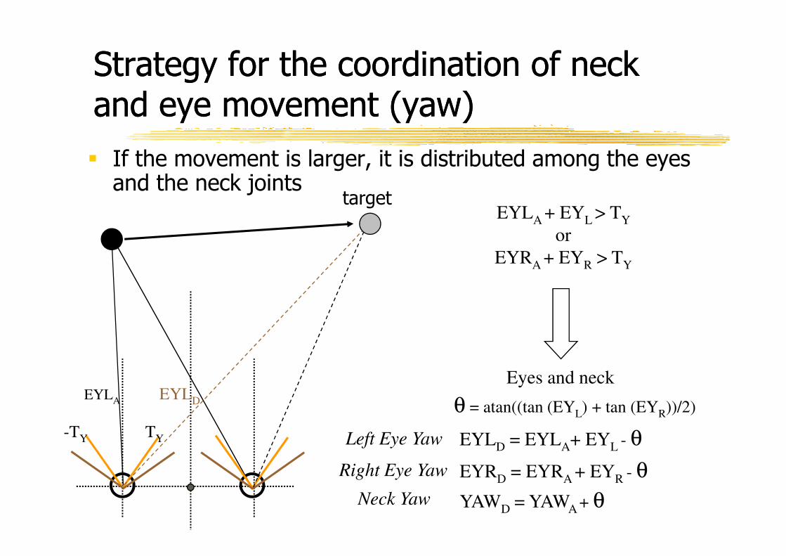
Strategy for the coordination of neck Strategy for the coordination of neck and eye movement (yaw)and eye movement (yaw)
targetEYLA + EYL > TY
or
EYRA + EYR > TY
� If the movement is larger, it is distributed among the eyes and the neck joints
EYLD = EYLA+ EYL - θ
EYRD = EYRA + EYR - θ
YAWD = YAWA + θ
Eyes and neck
θ = atan((tan (EYL) + tan (EYR))/2)
TY
EYLA EYLD
-TY Left Eye Yaw
Right Eye Yaw
Neck Yaw
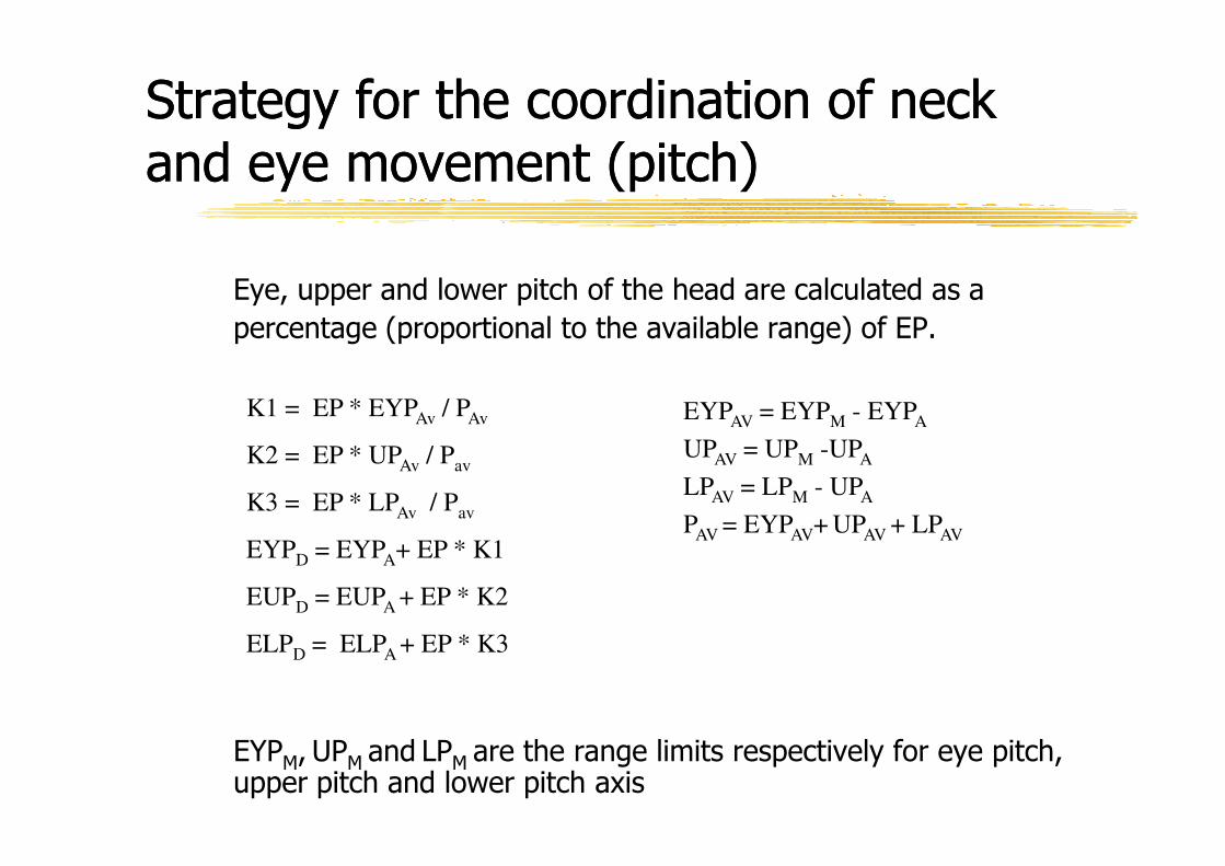
Strategy for the coordination of neck Strategy for the coordination of neck and eye movement (pitch)and eye movement (pitch)
Eye, upper and lower pitch of the head are calculated as a
percentage (proportional to the available range) of EP.
EYPAV = EYPM - EYPAK1 = EP * EYPAv / PAv
EYPM, UPM and LPM are the range limits respectively for eye pitch, upper pitch and lower pitch axis
UPAV = UPM -UPA
LPAV = LPM - UPA
PAV = EYPAV+ UPAV + LPAV
K2 = EP * UPAv / Pav
K3 = EP * LPAv / Pav
EYPD = EYPA+ EP * K1
EUPD = EUPA + EP * K2
ELPD = ELPA + EP * K3
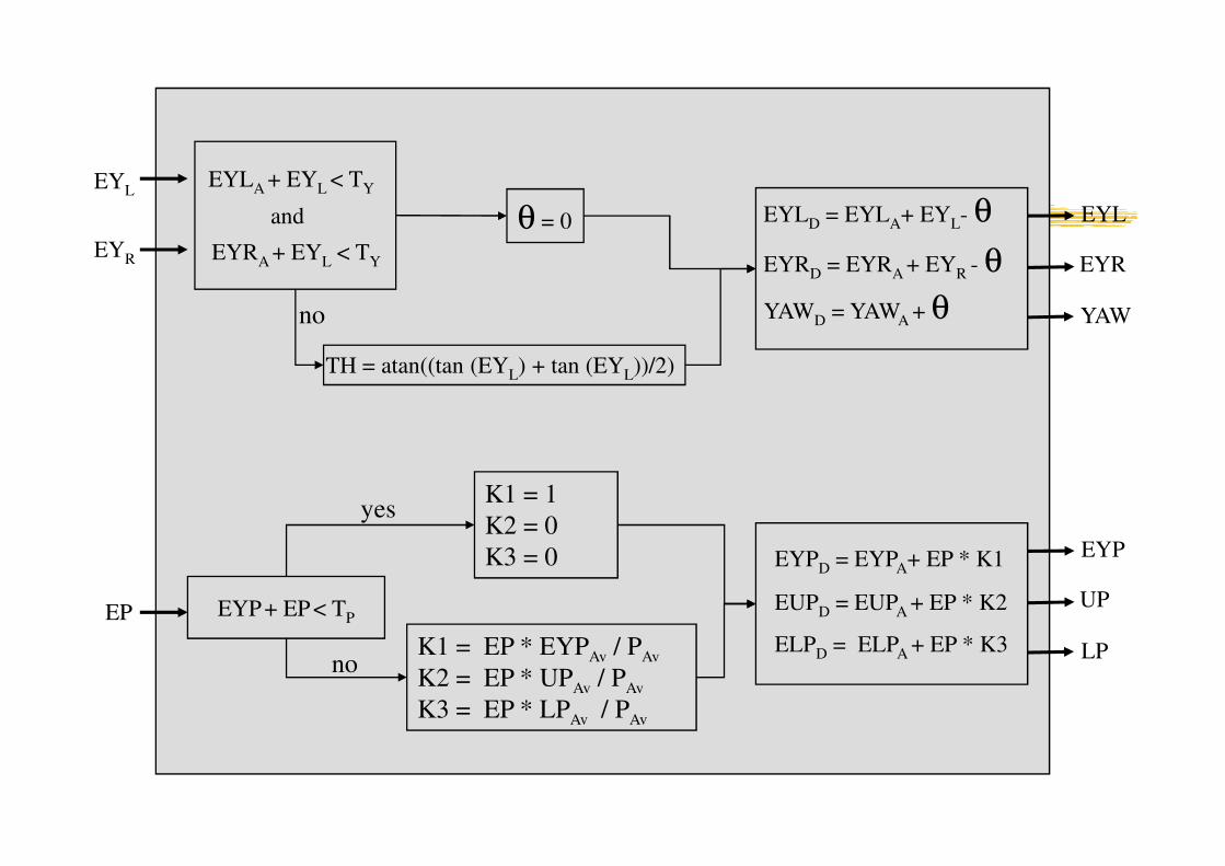
EYL
EYR
EYLD = EYLA+ EYL- θ
EYRD = EYRA + EYR - θ
YAWD = YAWA + θ
θ = 0
TH = atan((tan (EYL) + tan (EYL))/2)
EYLA + EYL < TY
EYRA + EYL < TY
and EYL
EYR
YAWno
EP EYP+ EP < TP
EYPD = EYPA+ EP * K1
EUPD = EUPA + EP * K2
ELPD = ELPA + EP * K3
EYP
UP
LP
K1 = 1
K2 = 0
K3 = 0
K1 = EP * EYPAv / PAv
K2 = EP * UPAv / PAv
K3 = EP * LPAv / PAv
yes
no
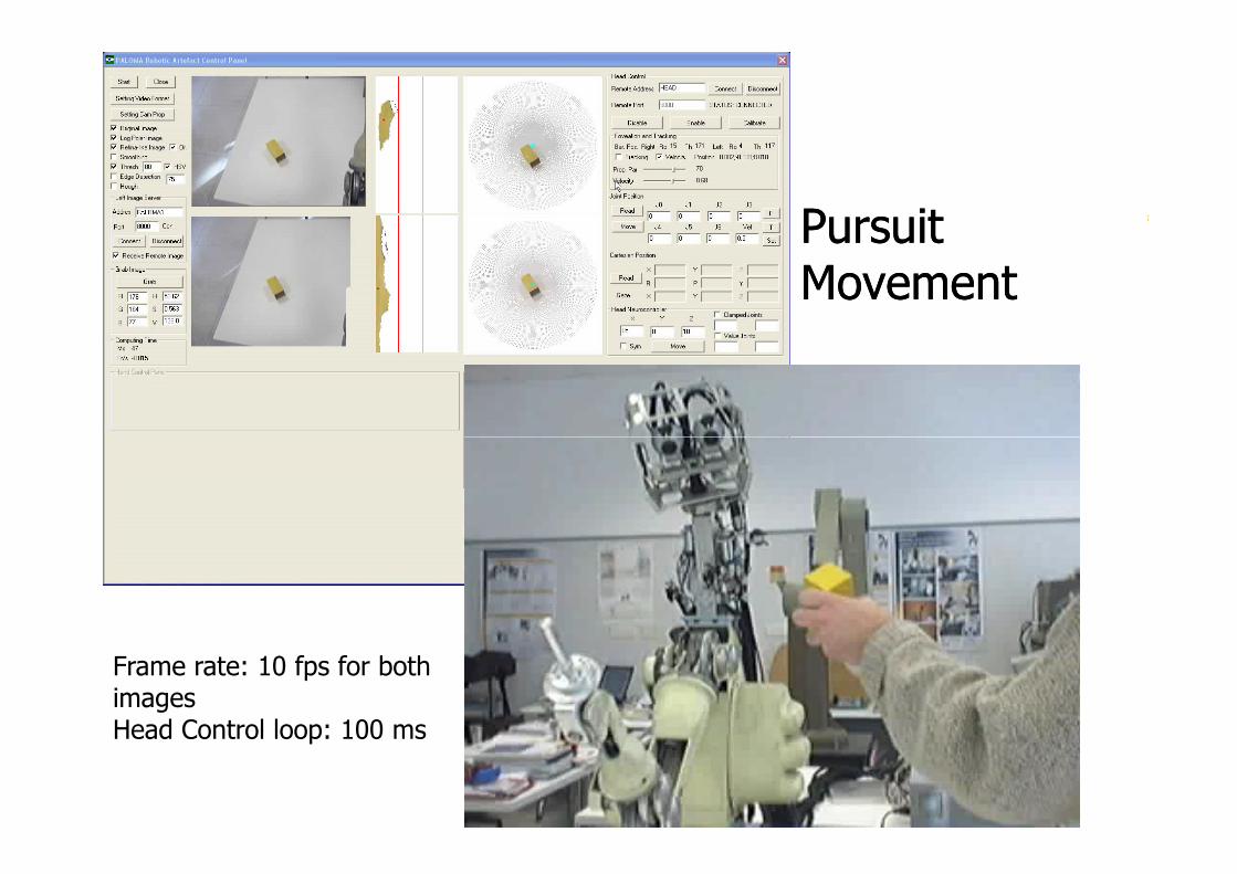
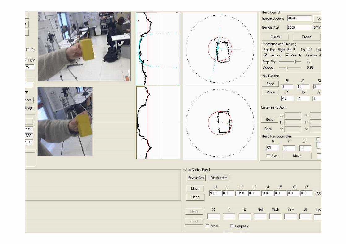
Pursuit Pursuit MovementMovement
Frame rate: 10 fps for both imagesHead Control loop: 100 ms
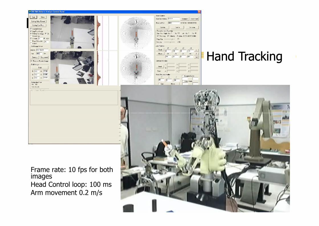
Robot Hand trackingRobot Hand tracking
Hand TrackingHand Tracking
Frame rate: 10 fps for both imagesHead Control loop: 100 msArm movement 0.2 m/s
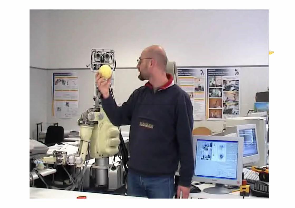
Implementation of a biological model of head-eye coordination
Solution 2
head-eye coordination
E.S. Maini, G. Teti, C. Laschi, M. Rubino, P. Dario, “Bio-inspired control of eye-head coordination in
a robotic anthropomorphic head”, IEEE/RAS-EMBS International Conference on Biomedical
Robotics and Biomechatronics, Pisa, Italy, February 20-22, 2006
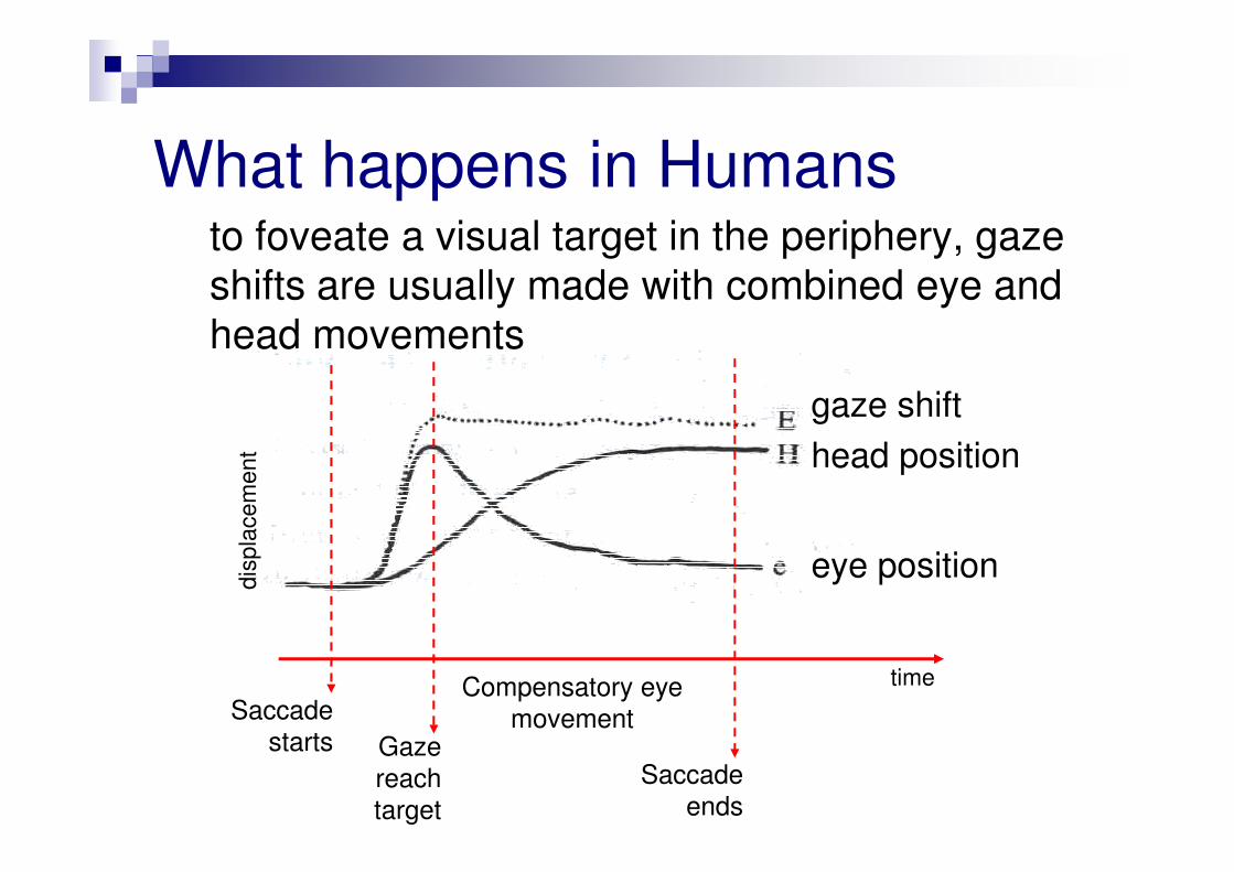
What happens in Humans
gaze shift
head position
to foveate a visual target in the periphery, gaze
shifts are usually made with combined eye and
head movements
head position
eye position
Saccade
starts Gaze
reach
target
Saccade
ends
Compensatory eye
movement
time
dis
pla
ce
me
nt
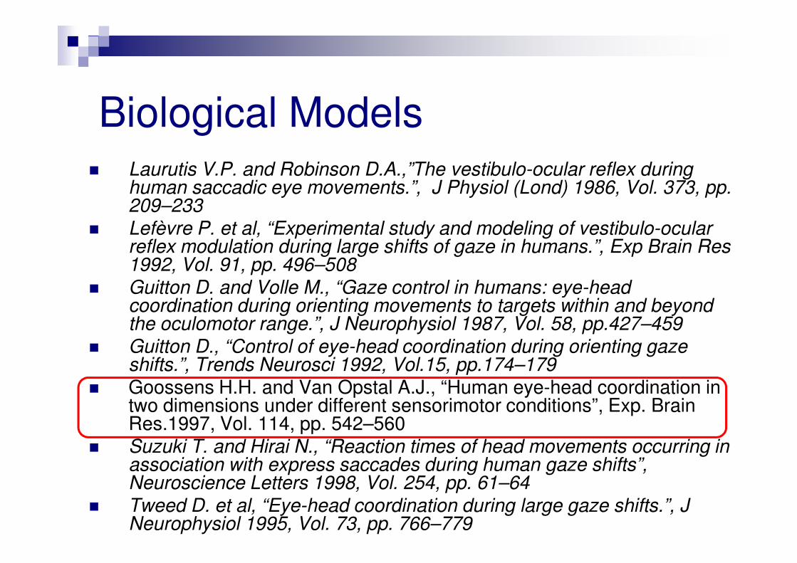
Biological Models� Laurutis V.P. and Robinson D.A.,”The vestibulo-ocular reflex during
human saccadic eye movements.”, J Physiol (Lond) 1986, Vol. 373, pp. 209–233
� Lefèvre P. et al, “Experimental study and modeling of vestibulo-ocular reflex modulation during large shifts of gaze in humans.”, Exp Brain Res 1992, Vol. 91, pp. 496–508
� Guitton D. and Volle M., “Gaze control in humans: eye-head � Guitton D. and Volle M., “Gaze control in humans: eye-head coordination during orienting movements to targets within and beyond the oculomotor range.”, J Neurophysiol 1987, Vol. 58, pp.427–459
� Guitton D., “Control of eye-head coordination during orienting gaze shifts.”, Trends Neurosci 1992, Vol.15, pp.174–179
� Goossens H.H. and Van Opstal A.J., “Human eye-head coordination in two dimensions under different sensorimotor conditions”, Exp. Brain Res.1997, Vol. 114, pp. 542–560
� Suzuki T. and Hirai N., “Reaction times of head movements occurring in association with express saccades during human gaze shifts”, Neuroscience Letters 1998, Vol. 254, pp. 61–64
� Tweed D. et al, “Eye-head coordination during large gaze shifts.”, J Neurophysiol 1995, Vol. 73, pp. 766–779
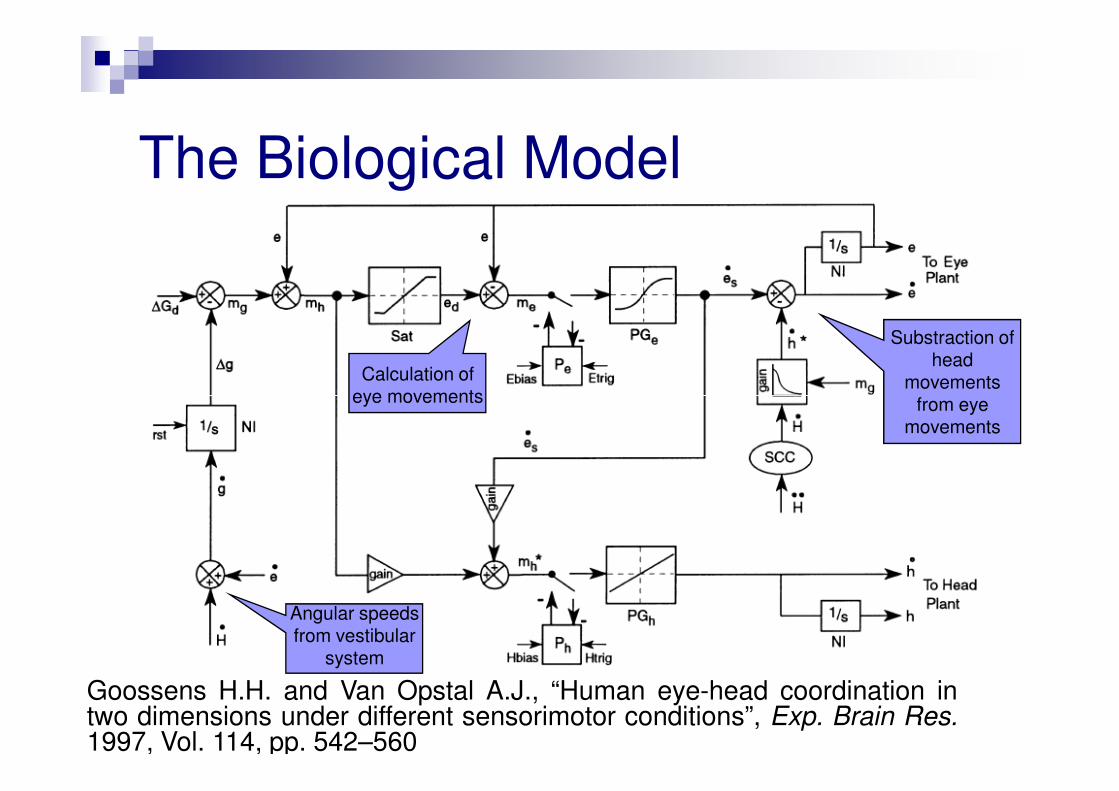
The Biological Model
Substraction of head
movements from eye
Calculation of eye movements
Goossens H.H. and Van Opstal A.J., “Human eye-head coordination intwo dimensions under different sensorimotor conditions”, Exp. Brain Res.1997, Vol. 114, pp. 542–560
Angular speeds from vestibular
system
from eye movements
eye movements
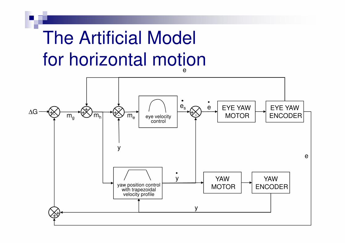
The Artificial Model
for horizontal motion
-- -+++∆G
EYE YAW
MOTOR
EYE YAW
ENCODER
e
e
mh eye velocity control
es+
mg
-+ me
++
yaw position control with trapezoidal velocity profile
YAW
MOTOR
YAW
ENCODER
y
y
control
y
e
Experimental trials
Objectives:
1. To investigate the effectiveness of the
bio-inspired paradigm to achieve an appropriate
control of a multi-DOF robotic headcontrol of a multi-DOF robotic head
2. To verify if the proposed control paradigm is able
to produce a motor output coherent with the
reported patterns of eye-head coordination in
humans
Experimental Methodology
In accordance to Goossens & Van Opstal two kinds of
experiments were done:
� aligned experiments: eyes and head of the robot were aligned at a straight-ahead position. were aligned at a straight-ahead position.
� not aligned experiments: the eyes of the robot were randomly deviated from the straight-ahead position with an initial deviation in the range 20°-55°.
� from the starting position the gaze shift was presented to the robot and the resulting displacements and timing of eye-head movements were recorded through the proprioceptive sensors of the head
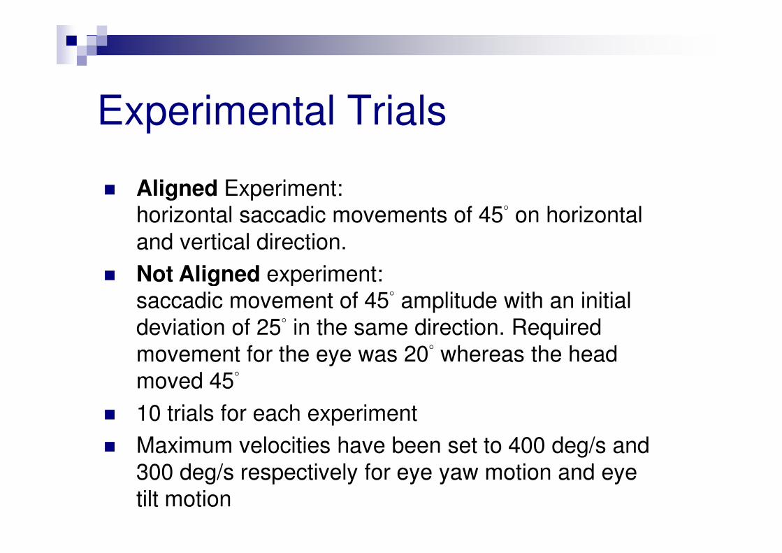
Experimental Trials
� Aligned Experiment:horizontal saccadic movements of 45° on horizontal
and vertical direction.
� Not Aligned experiment:� Not Aligned experiment:saccadic movement of 45° amplitude with an initial
deviation of 25° in the same direction. Required
movement for the eye was 20° whereas the head
moved 45°
� 10 trials for each experiment
� Maximum velocities have been set to 400 deg/s and
300 deg/s respectively for eye yaw motion and eye
tilt motion
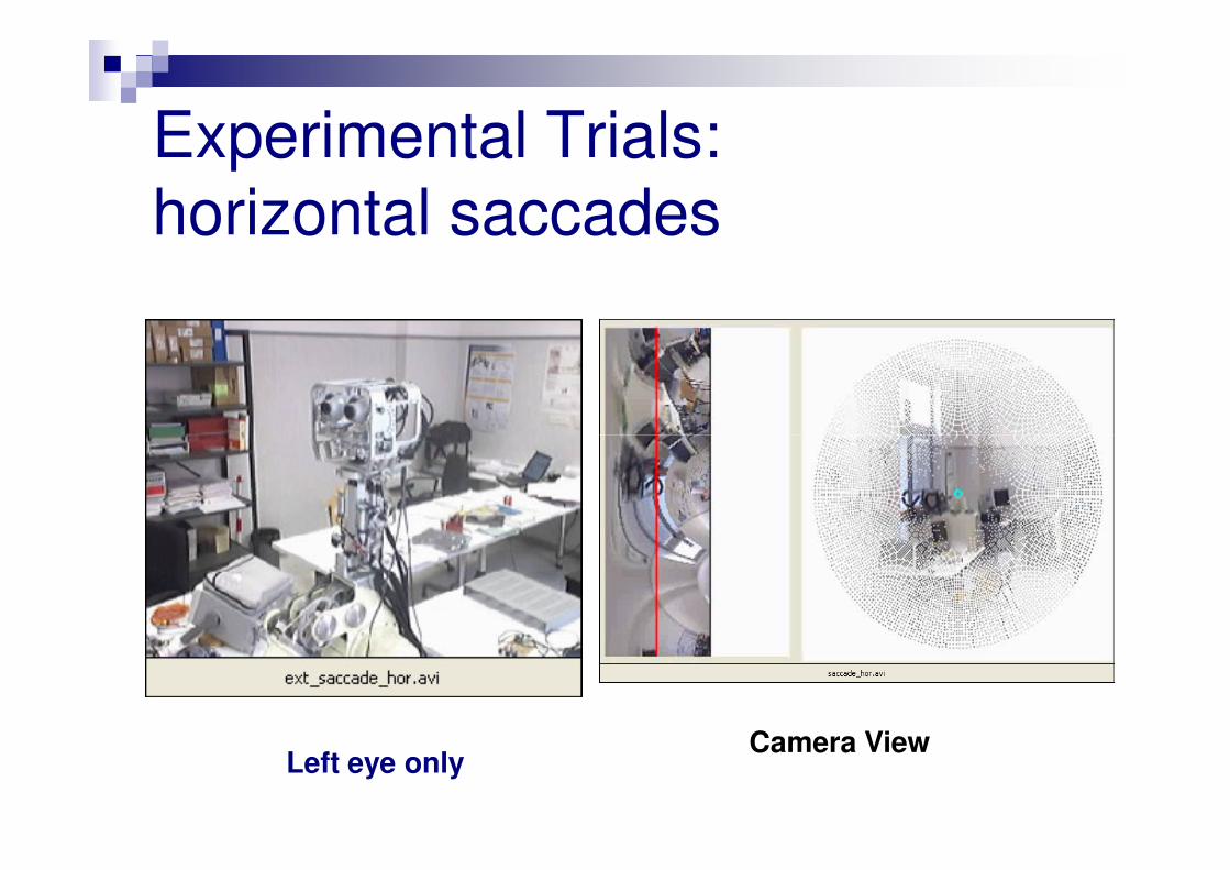
Experimental Trials:
horizontal saccades
Camera ViewLeft eye only
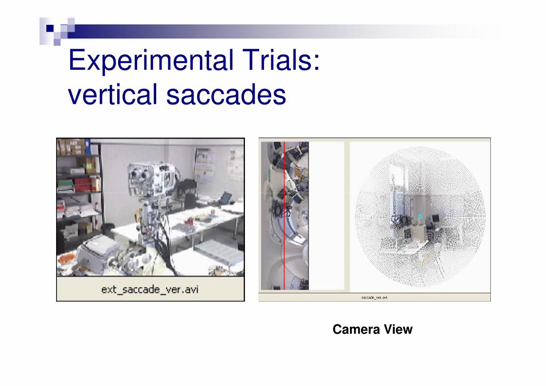
Experimental Trials:
vertical saccades
Camera View
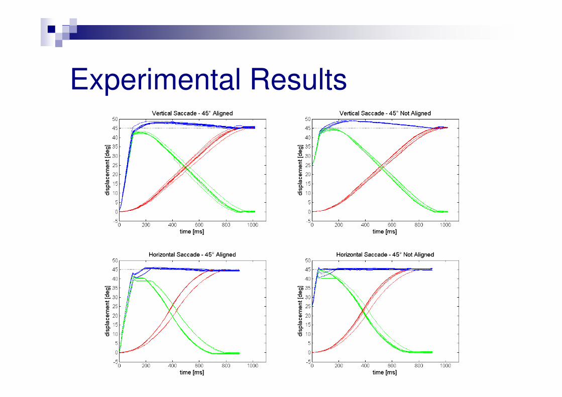
Experimental Results
Implementation of a bioinspired model of head-eye coordination
Solution 3
head-eye coordination based on learning
G. Asuni, G. Teti, C. Laschi, E. Guglielmelli, P. Dario, “A Robotic Head Neuro-controller Based on
Biologically-Inspired Neural Models”, IEEE International Conference on Robotics and Automation –
ICRA 2005, Barcelona, Spain, April 18-22, 2005, pp.2373-2378.
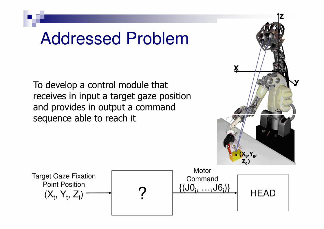
Addressed Problem
To develop a control module that receives in input a target gaze position and provides in output a command sequence able to reach it
Z
X
Y
sequence able to reach it
. (Xg,Yg, Zg)
Target Gaze Fixation
Point Position
(Xt, Yt, Zt) HEAD{(J0i, …,J6i)}?
Motor
Command
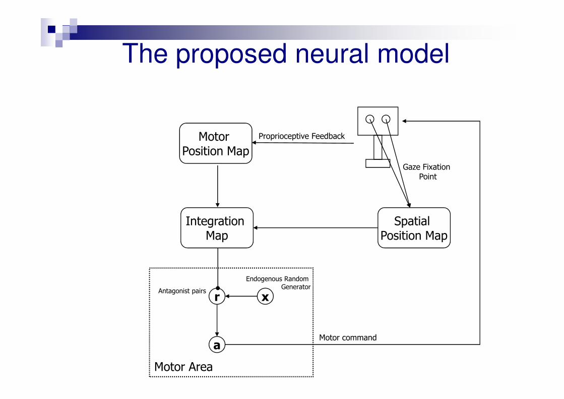
The proposed neural model
Motor Position Map
Proprioceptive Feedback
Gaze Fixation Point
Spatial Position Map
Integration Map
r
a
x
Endogenous Random Generator
Motor command
Antagonist pairs
Motor Area
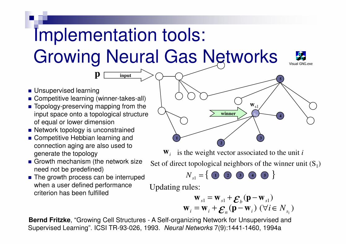
Implementation tools:
Growing Neural Gas Networksp input
s1
5
4winner
ws1
� Unsupervised learning
� Competitive learning (winner-takes-all)
� Topology-preserving mapping from the
input space onto a topological structure
of equal or lower dimension
Visual GNG.exe
3
2
1
{ } 1 =sN 1 2 3 4 5
Set of direct topological neighbors of the winner unit (S1):
is the weight vector associated to the unit i
)( 111 sbss wpww −+= ε)( inii wpww −+= ε )(
1sNi ∈∀
iw
Updating rules:
of equal or lower dimension
� Network topology is unconstrained
� Competitive Hebbian learning and
connection aging are also used to
generate the topology
� Growth mechanism (the network size
need not be predefined)
� The growth process can be interruped
when a user defined performance
criterion has been fulfilled
Bernd Fritzke, “Growing Cell Structures - A Self-organizing Network for Unsupervised and
Supervised Learning”. ICSI TR-93-026, 1993. Neural Networks 7(9):1441-1460, 1994a
Testing phase
� After the training phase, given a target fixation point the system provides the joint rotations that drives the current gaze fixation point in the target point
� Three different modalities:
1. Normal (without any constraint)
2. With a clamped joint 0
3. With symmetric angles for eye joints
All trials have been executed without additional learning
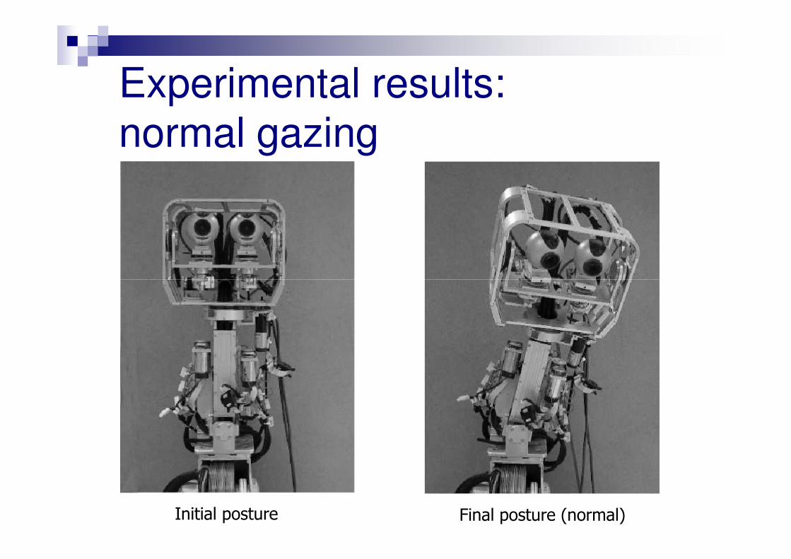
Experimental results:
normal gazing
Initial posture Final posture (normal)
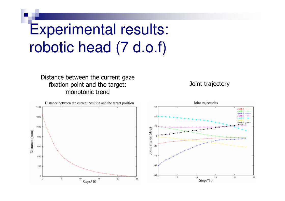
Distance between the current gaze fixation point and the target:
monotonic trend
Joint trajectory
Experimental results:
robotic head (7 d.o.f)
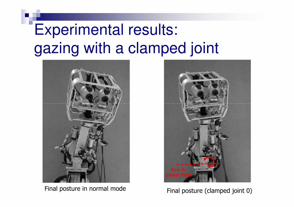
Experimental results:
gazing with a clamped joint
Final posture (clamped joint 0)
Axis 0,
Lower Pitch
Final posture in normal mode
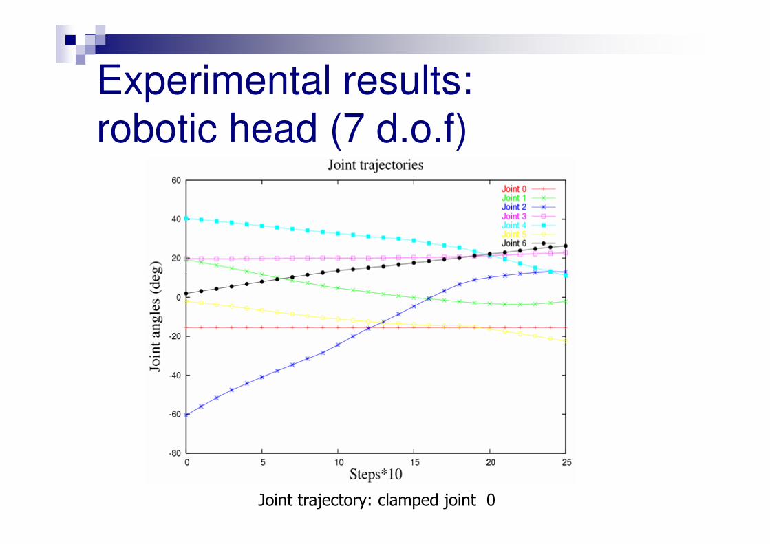
Experimental results:
robotic head (7 d.o.f)
Joint trajectory: clamped joint 0
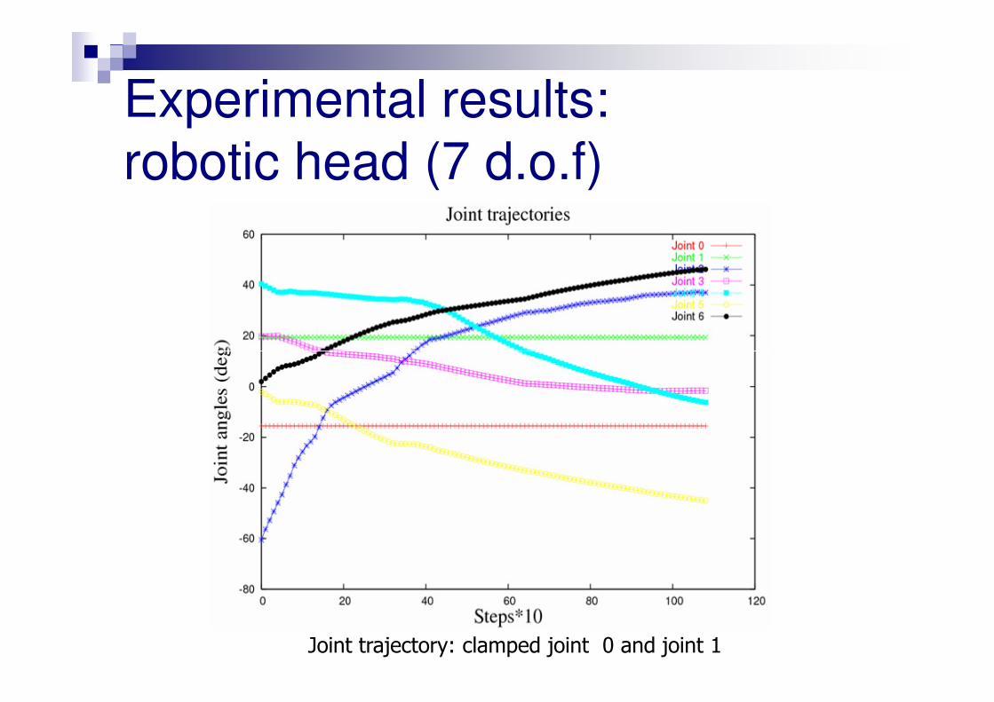
Experimental results:
robotic head (7 d.o.f)
Joint trajectory: clamped joint 0 and joint 1
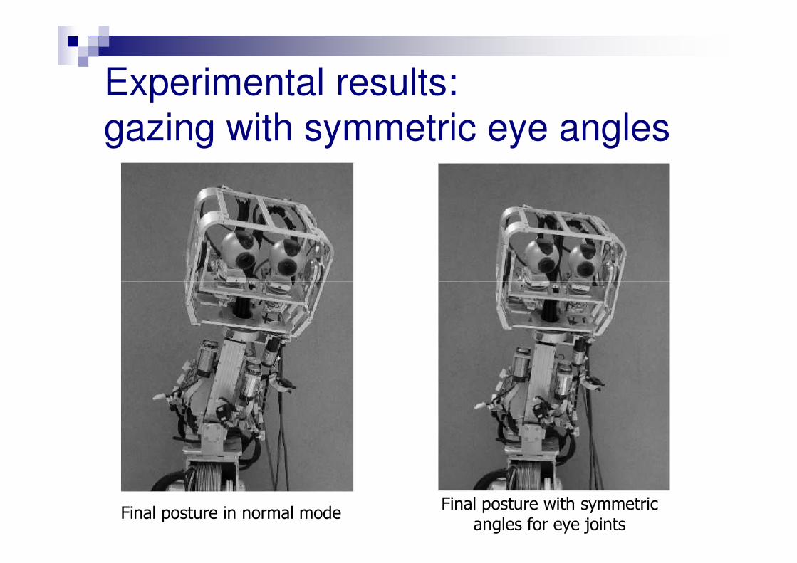
Experimental results:
gazing with symmetric eye angles
Final posture in normal modeFinal posture with symmetric
angles for eye joints
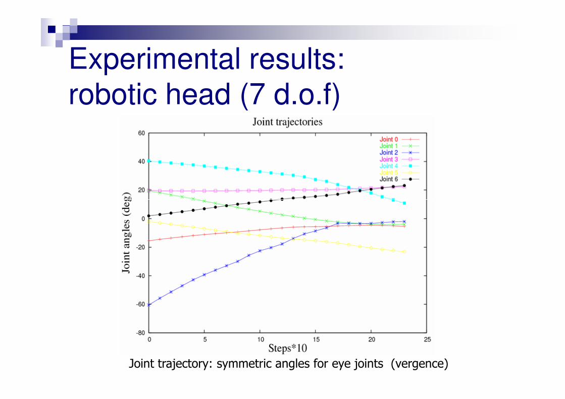
Experimental results:
robotic head (7 d.o.f)
Joint trajectory: symmetric angles for eye joints (vergence)
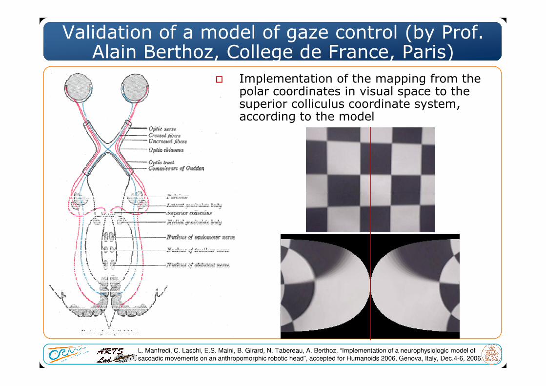
Validation of a model of gaze control (by Prof. Alain Berthoz, College de France, Paris)
� Implementation of the mapping from the polar coordinates in visual space to the superior colliculus coordinate system, according to the model
L. Manfredi, C. Laschi, E.S. Maini, B. Girard, N. Tabereau, A. Berthoz, “Implementation of a neurophysiologic model of
saccadic movements on an anthropomorphic robotic head”, accepted for Humanoids 2006, Genova, Italy, Dec.4-6, 2006.
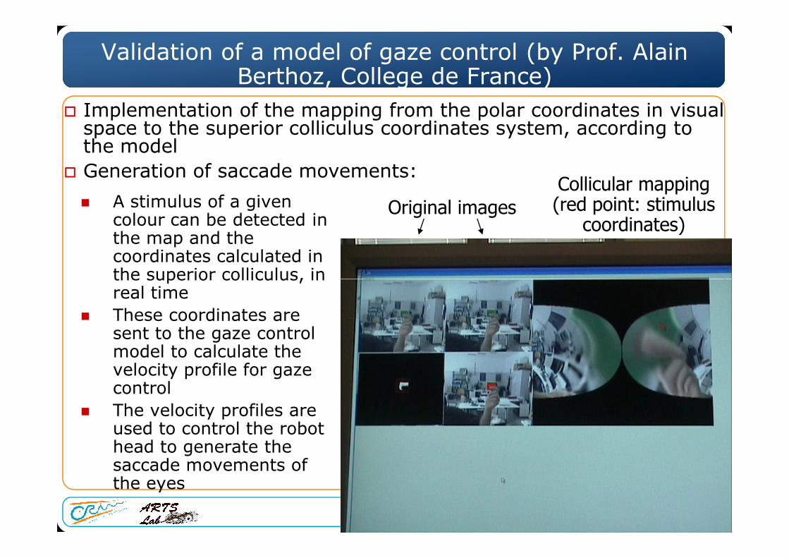
Validation of a model of gaze control (by Prof. Alain Berthoz, College de France)
� A stimulus of a given colour can be detected in the map and the coordinates calculated in the superior colliculus, in
Original imagesCollicular mapping(red point: stimulus
coordinates)
� Implementation of the mapping from the polar coordinates in visual space to the superior colliculus coordinates system, according to the model
� Generation of saccade movements:
the superior colliculus, in real time
� These coordinates are sent to the gaze control model to calculate the velocity profile for gaze control
� The velocity profiles are used to control the robot head to generate the saccade movements of the eyes
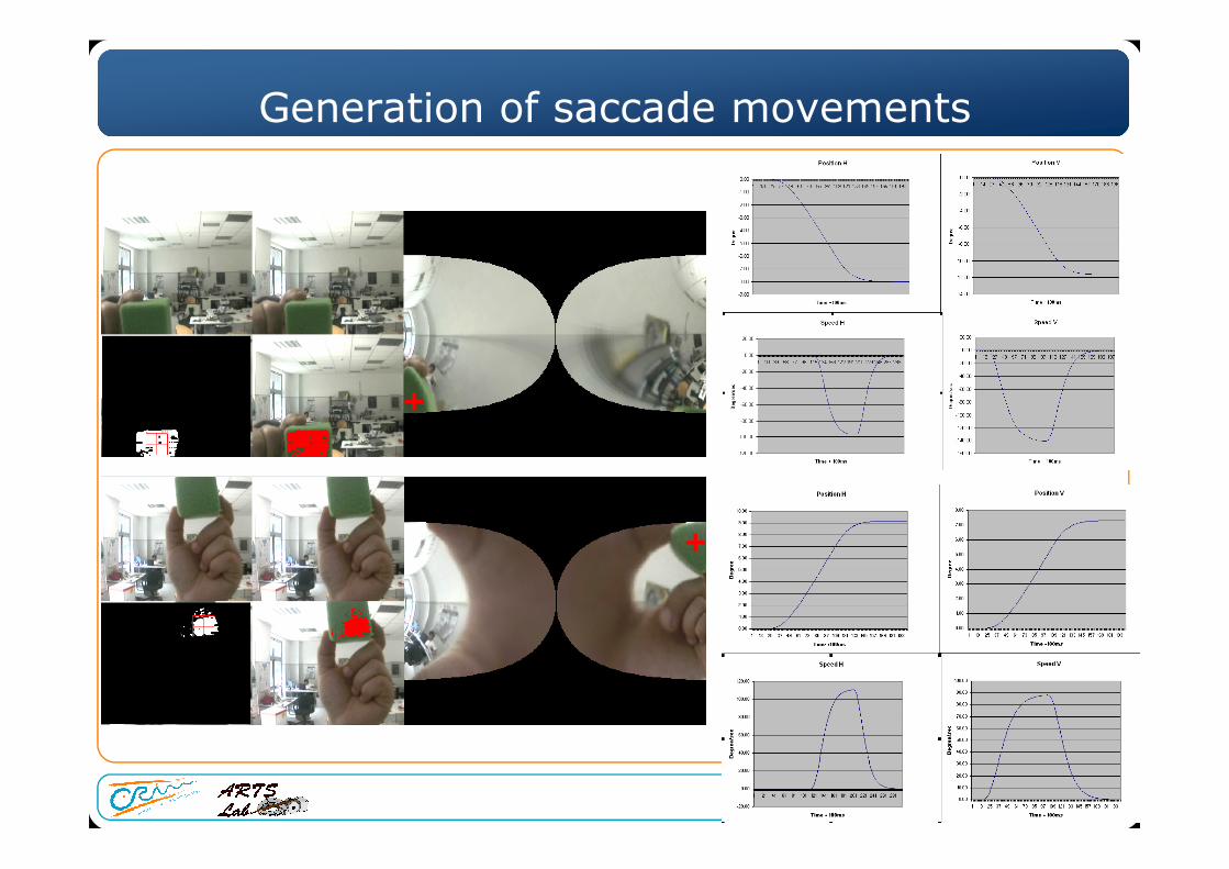
Generation of saccade movements
+
+
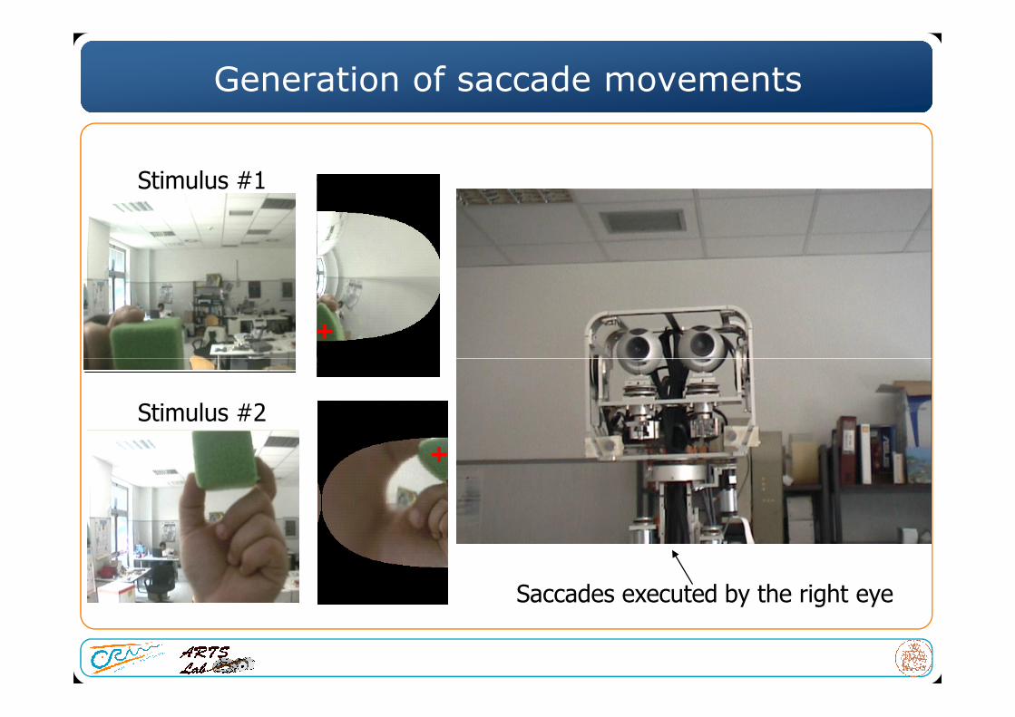
Generation of saccade movements
+
Stimulus #1
+
Stimulus #2
Saccades executed by the right eye


![Corso di Percezione Robotica - DidaWiki [DidaWiki]didawiki.cli.di.unipi.it/lib/exe/fetch.php/magistraleinformatica/... · Retina-like vision for visuo-motor co-ordination of a robot](https://static.fdocumenti.com/doc/165x107/5c683ab709d3f2ff5a8d3187/corso-di-percezione-robotica-didawiki-didawiki-retina-like-vision-for-visuo-motor.jpg)