![...Regione Emilia-Romagna A / Generatore numenxasuali Risultato generazione Generazione di 5 numeri distinti nell'intervallo [ 1, 43 ] Parametri del generatore: seme= 1041345, m =](https://static.fdocumenti.com/doc/165x107/5e8c2b82e0cc1047cd082064/-regione-emilia-romagna-a-generatore-numenxasuali-risultato-generazione-generazione.jpg)
Classe: Futura 5 ITT - salesianibologna.net · 2. Vero o falso? a. Una funzione costante verifica...
23
Classe: Futura 5 a ITT Si ricorda agli allievi che i compiti vanno riconsegnati con la seguente scadenza: - Allievi che hanno gli esami di recupero a settembre: in corrispondenza delle prove di recupero (la mancata consegna potrebbe avere una ricaduta negativa sulla valutazione della prova) - Allievi che hanno la lettera di avviso: in corrispondenza delle prove di inizio settembre (la mancata consegna potrebbe avere una ricaduta negativa sulla valutazione della prova) - Per tutti gli atri (che non hanno debiti e neppure lettere): i compiti vanno consegnati al docente della materia interessata entro la prima settimana di scuola Le materie non indicate non prevedono compiti per l’estate, salvo indicazioni personali comunicate dal Docente tramite lettera. ITALIANO Leggere i seguenti testi: Oscar Wilde, L’importanza di chiamarsi Ernesto, edizione a scelta; Paolo Malaguti, Prima dell’alba, Neri Pozza; (argomento: I guerra mondiale/fascismo) Anna Funder, C’era una volta la DDR, Feltrinelli; (argomento: Muro di Berlino) Clara Uson, La figlia, Sellerio. (argomento: la guerra nella ex Jugoslavia) Al rientro in classe, nelle prime settimane di scuola, questi testi saranno oggetto di verifica. Lettura facoltativa: Mario Rigoni Stern, Il sergente nella neve, da cui è tratto lo spettacolo teatrale di Paolini la cui visione è assegnata come compito estivo di storia. STORIA I compiti assegnati riguardano il programma di storia che sarà affrontato in quinta e consistono in video/film da guardare. Si trovano su varie piattaforme. Poiché al rientro a scuola saranno oggetto di verifica, è bene prendere qualche appunto durante la visione per non dimenticare i contenuti. Il sergente di Marco Paolini (spettacolo teatrale tratto da Il sergente nella neve di Mario Rigoni Stern); “El Alamein- La linea del fuoco”, regia di Monteleone, 2002; Il muro di Berlino - Il documentario (https://www.dailymotion.com/video/x28qfcu)
-
Upload
nguyennguyet -
Category
Documents
-
view
213 -
download
0
Transcript of Classe: Futura 5 ITT - salesianibologna.net · 2. Vero o falso? a. Una funzione costante verifica...
Classe: Futura 5a ITT
Si ricorda agli allievi che i compiti vanno riconsegnati con la seguente scadenza: - Allievi che hanno gli esami di recupero a settembre: in corrispondenza delle prove di recupero (la
mancata consegna potrebbe avere una ricaduta negativa sulla valutazione della prova) - Allievi che hanno la lettera di avviso: in corrispondenza delle prove di inizio settembre (la mancata
consegna potrebbe avere una ricaduta negativa sulla valutazione della prova) - Per tutti gli atri (che non hanno debiti e neppure lettere): i compiti vanno consegnati al docente
della materia interessata entro la prima settimana di scuola
Le materie non indicate non prevedono compiti per l’estate, salvo indicazioni personali comunicate dal Docente tramite lettera.
ITALIANO
Leggere i seguenti testi: Oscar Wilde, L’importanza di chiamarsi Ernesto, edizione a scelta; Paolo Malaguti, Prima dell’alba, Neri Pozza; (argomento: I guerra mondiale/fascismo) Anna Funder, C’era una volta la DDR, Feltrinelli; (argomento: Muro di Berlino) Clara Uson, La figlia, Sellerio. (argomento: la guerra nella ex Jugoslavia)
Al rientro in classe, nelle prime settimane di scuola, questi testi saranno oggetto di verifica. Lettura facoltativa:
Mario Rigoni Stern, Il sergente nella neve, da cui è tratto lo spettacolo teatrale di Paolini la cui visione è assegnata come compito estivo di storia.
STORIA
I compiti assegnati riguardano il programma di storia che sarà affrontato in quinta e consistono in video/film da guardare. Si trovano su varie piattaforme. Poiché al rientro a scuola saranno oggetto di verifica, è bene prendere qualche appunto durante la visione per non dimenticare i contenuti.
Il sergente di Marco Paolini (spettacolo teatrale tratto da Il sergente nella neve di Mario Rigoni Stern);
“El Alamein- La linea del fuoco”, regia di Monteleone, 2002;
Il muro di Berlino - Il documentario (https://www.dailymotion.com/video/x28qfcu)

INGLESE
Libro di testo: Smartmech, R.A. Rizzo, ELI edizioni
Leggere il seguente testo e svolgere gli esercizi proposti:
The Importance of Being Earnest Oscar Wilde
Black Cat edizioni Al rientro dalle vacanze, il libro sarà oggetto di una verifica.
MATEMATICA
Libro di testo: Bergamini-Barozzi- Trifone “ Matematica.verde” Vol. 4A-4B Zanichelli
Svolgere i seguenti esercizi
1. Indica quale delle seguenti funzioni verifica il teorema di Rolle nell'intervallo . ; ba Segna nel
grafico il punto (o i punti) in cui vale la relazione del teorema. Per le restanti funzioni specifica perché il teorema non è verificato.

2. Vero o falso?
a. Una funzione costante verifica le ipotesi del teorema di Lagrange per ogni valore di x
nell'intervallo
b. Dato l'intervallo ba ; , se la funzione )(xf verifica il teorema di Lagrange, allora lo verifica
anche .
c. Se )(xf soddisfa le ipotesi del teorema di Lagrange, allora il punto c , che esiste per la tesi del
teorema, non può mai essere unico.
d. Se )(xf è derivabile in , allora verifica le ipotesi del teorema di Lagrange in
e. La bisettrice del primo e terzo quadrante in 2 ;1 verifica le ipotesi del teorema di Lagrange e
ammette infiniti valori di x nell'intervallo aperto che ne verificano il teorema.
f. Dato l'intervallo ba ; , se la funzione )(xf verifica il teorema di Lagrange, allora lo verifica
anche xfy .
g. Se )(xf soddisfa le ipotesi del teorema di Lagrange, allora il punto c , che esiste per la tesi del
teorema, è sempre unico.
h. Se )(xf è derivabile in aa; , allora verifica le ipotesi del teorema di Lagrange in . ; aa
3. Date le seguenti funzioni, verifica che nell’intervallo indicato a fianco valgono le ipotesi del teorema di Cauchy e trova il punto (o i punti) la cui esistenza è assicurata dal teorema.
1
,2
f xx
2
,3
xg x
x
1; 2 .
4. Calcola i seguenti limiti.
a.
;12ln
lim20 xx
x
x
b.
;3sin
cos5lnlim
20 x
x
x
c. ;sin
lim2
2
0 xx
xx
x
d. 2
lim .xx
x x
e x
5. Vero o falso? Osserva il grafico
A
a. Il dominio della funzione è .
b. Non ci sono né massimi né minimi.
c. La funzione ha un solo asintoto.
d. Non ci sono flessi.
B
a. La funzione è dispari.
b. La funzione ha un punto di minimo.
c. La funzione ha un asintoto.
d. Non ci sono flessi.
. ; ba
)(xfey
ba; . ; ba
3R
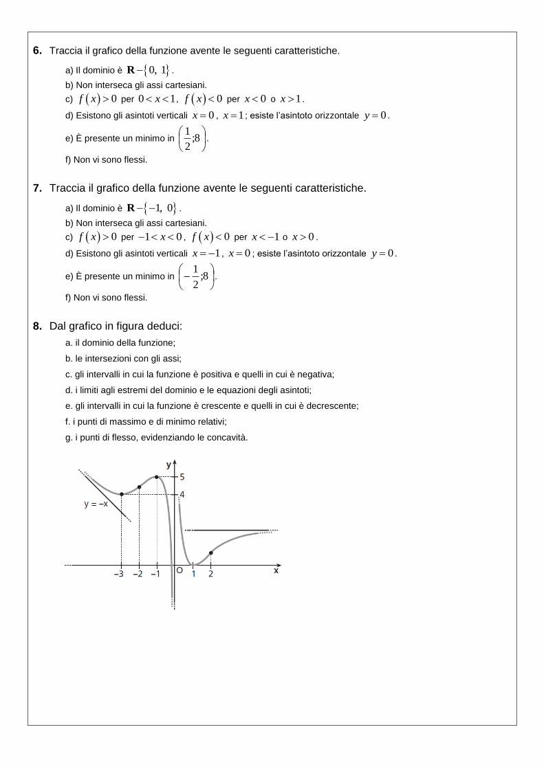
6. Traccia il grafico della funzione avente le seguenti caratteristiche.
a) Il dominio è 0, 1R .
b) Non interseca gli assi cartesiani.
c) 0f x per 0 1x , 0f x per 0x o 1x .
d) Esistono gli asintoti verticali 0x , 1x ; esiste l’asintoto orizzontale 0y .
e) È presente un minimo in
8;
2
1.
f) Non vi sono flessi.
7. Traccia il grafico della funzione avente le seguenti caratteristiche.
a) Il dominio è 1, 0 R .
b) Non interseca gli assi cartesiani.
c) 0f x per 1 0x , 0f x per 1x o 0x .
d) Esistono gli asintoti verticali 1x , 0x ; esiste l’asintoto orizzontale 0y .
e) È presente un minimo in
8;
2
1.
f) Non vi sono flessi.
8. Dal grafico in figura deduci:
a. il dominio della funzione;
b. le intersezioni con gli assi;
c. gli intervalli in cui la funzione è positiva e quelli in cui è negativa;
d. i limiti agli estremi del dominio e le equazioni degli asintoti;
e. gli intervalli in cui la funzione è crescente e quelli in cui è decrescente;
f. i punti di massimo e di minimo relativi;
g. i punti di flesso, evidenziando le concavità.
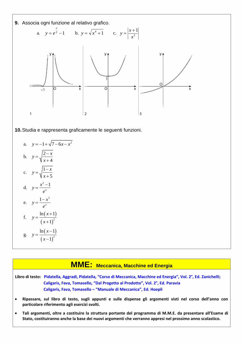
9. Associa ogni funzione al relativo grafico.
a. 12
x
ey b. 14 xy c. 3
1
x
xy
10. Studia e rappresenta graficamente le seguenti funzioni.
a. 21 7 6y x x
b. 2
4
xy
x
c. 1
5
xy
x
d. 2 1
x
xy
e
e. 21
x
xy
e
f.
2
ln 1
1
xy
x
g.
2
ln 1
1
xy
x
MME: Meccanica, Macchine ed Energia
Libro di testo: Pidatella, Aggradi, Pidatella, “Corso di Meccanica, Macchine ed Energia”, Vol. 2°, Ed. Zanichelli;
Caligaris, Fava, Tomasello, “Dal Progetto al Prodotto”, Vol. 2°, Ed. Paravia
Caligaris, Fava, Tomasello – “Manuale di Meccanica”, Ed. Hoepli
Ripassare, sul libro di testo, sugli appunti e sulle dispense gli argomenti visti nel corso dell’anno con particolare riferimento agli esercizi svolti.
Tali argomenti, oltre a costituire la struttura portante del programma di M.M.E. da presentare all’Esame di Stato, costituiranno anche la base dei nuovi argomenti che verranno appresi nel prossimo anno scolastico.

TMP: Tecnologie Meccaniche di Processo e Prodotto
Libro di testo: Dispense redatte dal Docente
Di Gennaro, Chiappetta, Chillemi, - “Corso di Tecnologia Meccanica”- Ed. Hoepli – Vol. 1°/ 2°
Caligaris, Fava, Tomasello – “Manuale di Meccanica”, Ed. Hoepli
Ripassare, sul libro di testo, sugli appunti e sulle dispense gli argomenti visti nel corso dell’anno con particolare riferimento agli esercizi svolti.
Tali argomenti, oltre a costituire la struttura portante del programma di T.M.P.P. da presentare all’Esame di Stato, costituiranno anche la base dei nuovi argomenti che verranno appresi nel prossimo anno scolastico.
DPO: Disegno, progettazione e organizzazione industriale
Libro di testo: Caligaris – “Dal progetto al prodotto” – Vol. 1,2 – Ed. Paravia 1. Estrapola i particolari relativi al complessivo sottoriportato, contrassegnati con la denominazione:
montante
albero
base
puleggia
boccola
e per ciascuno realizza il disegno costruttivo su foglio A4 bianco sotto forma di schizzo o in scala, completo di: cartiglio (contenente le principali informazioni generali) quote tolleranze dimensionali e geometriche rugosità scelta del materiale (da riportare sul retro del foglio) ciclo di lavorazione per la realizzazione del particolare (da riportare sul retro del foglio)
2. Facendo riferimento alla tua recente esperienza di Stage:
descrivi un progetto nel quale tu sei stato coinvolto (potrebbe essere anche un montaggio meccanico) ed in cosa sono consistite le fasi in cui si è sviluppato (fattibilità, pianificazione, risorse, esecuzione, monitoraggio, completamento);
descrivi, per quello che hai potuto vedere/apprendere: - che tipo di azienda è e la sua organizzazione (anche limitatamente all’intorno della tua postazione di
lavoro) - se è impegnata nella innovazione dei processi produttivi e/o nei prodotti - se hanno mai parlato di “Industria 4.0” - dove ritieni che le “soft skills” siano servite a te o a qualcuno con cui hai lavorato per migliorare il clima
di lavoro e/o la qualità del risultato.
Individua un obiettivo “SMART” del tuo futuro professionale, alla luce dell’esperienza fatta.

SIS: Sistemi e Automazione
Studiare i seguenti circuiti ricavandone una relazione con le proprie considerazioni scritte in italiano. Usare i libri e documenti digitali caricati, durante l’anno sul registro elettronico, dal docente. 1. Arduino DC Motor Speed and Direction Control using Relays and MOSFET
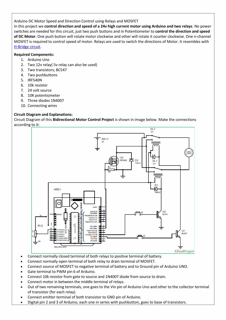
Arduino DC Motor Speed and Direction Control using Relays and MOSFET In this project we control direction and speed of a 24v high current motor using Arduino and two relays. No power switches are needed for this circuit, just two push buttons and in Potentiometer to control the direction and speed of DC Motor. One push button will rotate motor clockwise and other will rotate it counter clockwise. One n-channel MOSFET is required to control speed of motor. Relays are used to switch the directions of Motor. It resembles with H-Bridge circuit.
Required Components: 1. Arduino Uno 2. Two 12v relay( 5v relay can also be used) 3. Two transistors; BC547 4. Two pushbuttons 5. IRF540N 6. 10k resistor 7. 24 volt source 8. 10K potentiometer 9. Three diodes 1N4007 10. Connecting wires
Circuit Diagram and Explanations: Circuit Diagram of this Bidirectional Motor Control Project is shown in image below. Make the connections according to it:
Connect normally closed terminal of both relays to positive terminal of battery. Connect normally open terminal of both relay to drain terminal of MOSFET. Connect source of MOSFET to negative terminal of battery and to Ground pin of Arduino UNO. Gate terminal to PWM pin 6 of Arduino. Connect 10k resistor from gate to source and 1N4007 diode from source to drain. Connect motor in between the middle terminal of relays. Out of two remaining terminals, one goes to the Vin pin of Arduino Uno and other to the collector terminal
of transistor (for each relay). Connect emitter terminal of both transistor to GND pin of Arduino. Digital pin 2 and 3 of Arduino, each one in series with pushbutton, goes to base of transistors.

Connect diode across relay exactly as shown in figure. Connect Potentiometer's end terminal to 5v pin and Gnd pin of Arduino respectively. And wiper terminal to
A0 pin. ** if you have two separate 12 v battery then connect one battery’s positive terminal to the negative
terminal of another battery and use remaining two terminals as positive and negative.
Purpose of Transistors: Digital pins of Arduino cannot supply the amount of current needed to turn on a normal 5v relay. Besides we are using 12v relay in this project. Vin pin of Arduino cannot easily supply this much current for both relay. Hence transistors are used to conduct current from Vin pin of Arduino to relay which is controlled using a push-button connected from digital pin to base terminal of transistor. Purpose of Arduino:
To provide the amount of current required to turn on relay. To turn on transistor. To control the Speed of DC Motors with Potentiometer using Programming. Check the complete Arduino
Code at the end. Purpose of MOSFET: MOSFET is required to control the speed of motor. MOSFET is switched on and off at high frequency voltage and since motor is connected in series with the drain of MOSFET, PWM value of voltage determines the speed of motor. Current Calculations: Resistance of relay coil is measured using a multimeter which turn out to be = 400 ohms Vin pin of Arduino gives = 12v So current need to turn on the relay = 12/400 Amps = 30 mA If both relays are energized, current= 30*2=60 mA **Vin pin of Arduino can supply maximum current = 200mA. Thus there is no over current problem in Arduino. Working of Arduino Controlled Bi-directional Motor: Operation of this 2-way Motor Control circuit is simple. Both pins( 2 , 3 ) of Arduino will remain always high.
When no pushbutton is pressed: In this case no current flows to the base of transistor, hence transistor remains off ( acts like an open switch) due to

which no current flows to relay coil from Vin pin of Arduino. When one push button is pressed: In this case some current flows to the base of transistor through pressed push button which turns it on. Now current easily flows to relay coil from Vin pin through this transistor which turn this relay (RELAY A) on and switch of this relay is thrown to NO position. While other relay (RELAY B) is still in NC position. So current flows from positive terminal of battery to negative terminal through motor i.e., current flows from relay A to relay B .This causes clockwise rotation of motor. When other push button is pressed: This time another relay turns on. Now current easily flows to relay coil from Vin pin through transistor which turn this relay (RELAY B) on and switch of this relay is thrown to NO position. While other relay (RELAY A) remains in NC position. So current flows from positive terminal of battery to negative terminal of battery through motor. But this time current flows from relay B to relay A. This causes anticlockwise rotation of motor . When both push buttons are pressed: In this case current flows to the base of both transistors due to which both transistor turns on (acts like an closed switch). And thus both relay is now in NO position. So current do not flow from positive terminal of battery to negative terminal through motor and thus it does not rotate. Controlling the Speed of DC Motor: Gate of MOSFET is connected to PWM pin 6 of Arduino UNO. Mosfet is switched on and off at high PWM frequency voltage and since motor is connected in series with the drain of mosfet, PWM value of voltage determines the speed of motor. Now the voltage between the wiper terminal of potentiometer and Gnd determines the PWM voltage at pin no 6 and as wiper terminal is rotated, voltage at analog pin A0 changes causing change in speed of motor. Complete working of this Arduino Based Bi-directional Motor Speed and Direction control is shown in the Video below with the Arduino Code. Code:
int x; int y; void setup() { pinMode(2,OUTPUT); pinMode(3,OUTPUT); pinMode(6,OUTPUT); pinMode(A0,INPUT); } void loop() { x=analogRead(A0); y=map(x,0,1023,0,255); analogWrite(6,y); digitalWrite(2,HIGH); digitalWrite(3,HIGH); }
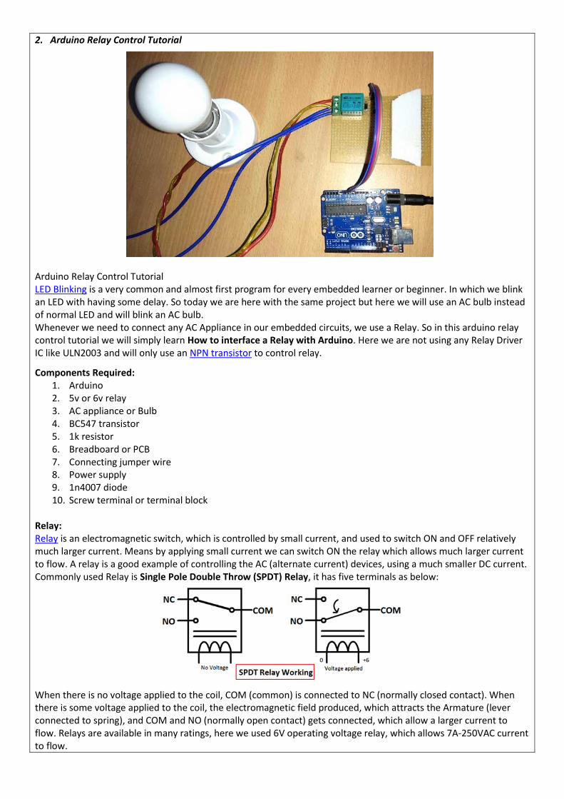
2. Arduino Relay Control Tutorial
Arduino Relay Control Tutorial LED Blinking is a very common and almost first program for every embedded learner or beginner. In which we blink an LED with having some delay. So today we are here with the same project but here we will use an AC bulb instead of normal LED and will blink an AC bulb. Whenever we need to connect any AC Appliance in our embedded circuits, we use a Relay. So in this arduino relay control tutorial we will simply learn How to interface a Relay with Arduino. Here we are not using any Relay Driver IC like ULN2003 and will only use an NPN transistor to control relay.
Components Required: 1. Arduino 2. 5v or 6v relay 3. AC appliance or Bulb 4. BC547 transistor 5. 1k resistor 6. Breadboard or PCB 7. Connecting jumper wire 8. Power supply 9. 1n4007 diode 10. Screw terminal or terminal block
Relay: Relay is an electromagnetic switch, which is controlled by small current, and used to switch ON and OFF relatively much larger current. Means by applying small current we can switch ON the relay which allows much larger current to flow. A relay is a good example of controlling the AC (alternate current) devices, using a much smaller DC current. Commonly used Relay is Single Pole Double Throw (SPDT) Relay, it has five terminals as below:
When there is no voltage applied to the coil, COM (common) is connected to NC (normally closed contact). When there is some voltage applied to the coil, the electromagnetic field produced, which attracts the Armature (lever connected to spring), and COM and NO (normally open contact) gets connected, which allow a larger current to flow. Relays are available in many ratings, here we used 6V operating voltage relay, which allows 7A-250VAC current to flow.

The relay is always configured by using a small Driver circuit which consists a Transistor, Diode and a resistor. Transistor is used to amplify the current so that full current (from the DC source – 9v battery) can flow through a coil to fully energies it. The resistor is used to provide biasing to the transistor. And Diode is used to prevent reverse current flow, when the transistor is switched OFF. Every Inductor coil produces equal and opposite EMF when switched OFF suddenly, this may cause permanent damage to components, so Diode must be used to prevent reverse current. A Relay module is easily available in the market with all its Driver circuit on the board or you can create it on perf board or PCB like below. Here we have used 6V Relay module.
Here to turn on the Relay with Arduino we just need to make that Arduino Pin High (A0 in our case) where Relay module is connected. Below given is Relay Driver Circuit to build your own Relay module:
Relay Driver Circuit Circuit Diagram and Working:

In this Arduino Relay Control Circuit we have used Arduino to control the relay via a BC547 transistor. We have connected transistor base to Arduino pin A0 through a 1k resistor. An AC bulb is used for demonstration. The 12v adaptor is used for powering the circuit.
Working is simple, we need to make the RELAY Pin (PIN A0) high to make the Relay module ON and make the RELAY pin low to turn off the Relay Module. The AC light will also turn on and off according to Relay. We just programmed the Arduino to make the Relay Pin (A0) High and Low with a delay of 1 second:
void loop() { digitalWrite(relay, HIGH); delay(interval); digitalWrite(relay, LOW); delay(interval); }
Demonstration Video and complete code for Arduino Relay Control is given below. Code:
// Arduino Relay Control Code #define relay A0 #define interval 1000 void setup() { pinMode(relay, OUTPUT); } void loop() { digitalWrite(relay, HIGH); delay(interval); digitalWrite(relay, LOW); delay(interval); }
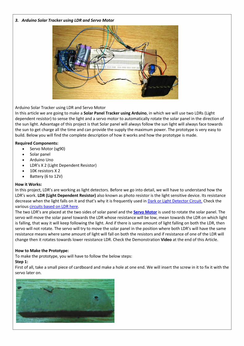
3. Arduino Solar Tracker using LDR and Servo Motor
Arduino Solar Tracker using LDR and Servo Motor In this article we are going to make a Solar Panel Tracker using Arduino, in which we will use two LDRs (Light dependent resistor) to sense the light and a servo motor to automatically rotate the solar panel in the direction of the sun light. Advantage of this project is that Solar panel will always follow the sun light will always face towards the sun to get charge all the time and can provide the supply the maximum power. The prototype is very easy to build. Below you will find the complete description of how it works and how the prototype is made.
Required Components: Servo Motor (sg90) Solar panel Arduino Uno LDR’s X 2 (Light Dependent Resistor) 10K resistors X 2 Battery (6 to 12V)
How it Works: In this project, LDR’s are working as light detectors. Before we go into detail, we will have to understand how the LDR’s work. LDR (Light Dependent Resistor) also known as photo resistor is the light sensitive device. Its resistance decrease when the light falls on it and that’s why it is frequently used in Dark or Light Detector Circuit. Check the various circuits based on LDR here. The two LDR’s are placed at the two sides of solar panel and the Servo Motor is used to rotate the solar panel. The servo will move the solar panel towards the LDR whose resistance will be low, mean towards the LDR on which light is falling, that way it will keep following the light. And if there is same amount of light falling on both the LDR, then servo will not rotate. The servo will try to move the solar panel in the position where both LDR’s will have the same resistance means where same amount of light will fall on both the resistors and if resistance of one of the LDR will change then it rotates towards lower resistance LDR. Check the Demonstration Video at the end of this Article.
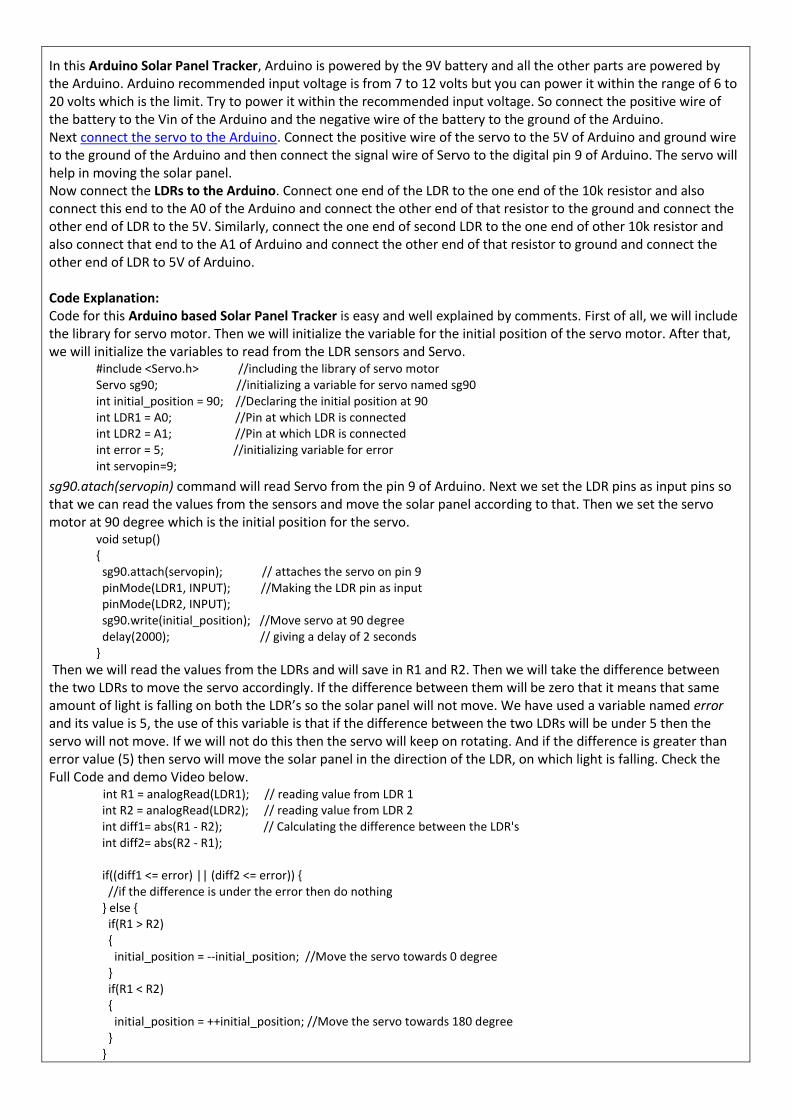
How to Make the Prototype: To make the prototype, you will have to follow the below steps: Step 1: First of all, take a small piece of cardboard and make a hole at one end. We will insert the screw in it to fix it with the servo later on.
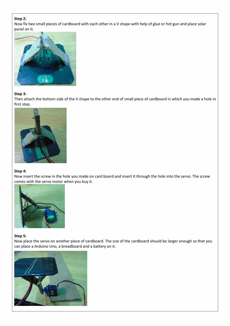
Step 2: Now fix two small pieces of cardboard with each other in a V shape with help of glue or hot gun and place solar panel on it.
Step 3: Then attach the bottom side of the V shape to the other end of small piece of cardboard in which you made a hole in first step.
Step 4: Now insert the screw in the hole you made on card board and insert it through the hole into the servo. The screw comes with the servo motor when you buy it.
Step 5: Now place the servo on another piece of cardboard. The size of the cardboard should be larger enough so that you can place a Arduino Uno, a breadboard and a battery on it.

Step 6: Attach the LDRs on the two sides of the solar panel with the help of glue. Make sure you have soldered the wires with the legs of the LDR’s. You will have to connect these with the resistors later on.
Step 7: Now place the Arduino, battery and the breadboard on the cardboard and make the connection as described in the Circuit diagram and Explanation section below. The final prototype is shown below.
Circuit Diagram and Explanation:
In this Arduino Solar Panel Tracker, Arduino is powered by the 9V battery and all the other parts are powered by the Arduino. Arduino recommended input voltage is from 7 to 12 volts but you can power it within the range of 6 to 20 volts which is the limit. Try to power it within the recommended input voltage. So connect the positive wire of the battery to the Vin of the Arduino and the negative wire of the battery to the ground of the Arduino. Next connect the servo to the Arduino. Connect the positive wire of the servo to the 5V of Arduino and ground wire to the ground of the Arduino and then connect the signal wire of Servo to the digital pin 9 of Arduino. The servo will help in moving the solar panel. Now connect the LDRs to the Arduino. Connect one end of the LDR to the one end of the 10k resistor and also connect this end to the A0 of the Arduino and connect the other end of that resistor to the ground and connect the other end of LDR to the 5V. Similarly, connect the one end of second LDR to the one end of other 10k resistor and also connect that end to the A1 of Arduino and connect the other end of that resistor to ground and connect the other end of LDR to 5V of Arduino. Code Explanation: Code for this Arduino based Solar Panel Tracker is easy and well explained by comments. First of all, we will include the library for servo motor. Then we will initialize the variable for the initial position of the servo motor. After that, we will initialize the variables to read from the LDR sensors and Servo.
#include <Servo.h> //including the library of servo motor Servo sg90; //initializing a variable for servo named sg90 int initial_position = 90; //Declaring the initial position at 90 int LDR1 = A0; //Pin at which LDR is connected int LDR2 = A1; //Pin at which LDR is connected int error = 5; //initializing variable for error int servopin=9;
sg90.atach(servopin) command will read Servo from the pin 9 of Arduino. Next we set the LDR pins as input pins so that we can read the values from the sensors and move the solar panel according to that. Then we set the servo motor at 90 degree which is the initial position for the servo.
void setup() { sg90.attach(servopin); // attaches the servo on pin 9 pinMode(LDR1, INPUT); //Making the LDR pin as input pinMode(LDR2, INPUT); sg90.write(initial_position); //Move servo at 90 degree delay(2000); // giving a delay of 2 seconds }
Then we will read the values from the LDRs and will save in R1 and R2. Then we will take the difference between the two LDRs to move the servo accordingly. If the difference between them will be zero that it means that same amount of light is falling on both the LDR’s so the solar panel will not move. We have used a variable named error and its value is 5, the use of this variable is that if the difference between the two LDRs will be under 5 then the servo will not move. If we will not do this then the servo will keep on rotating. And if the difference is greater than error value (5) then servo will move the solar panel in the direction of the LDR, on which light is falling. Check the Full Code and demo Video below.
int R1 = analogRead(LDR1); // reading value from LDR 1 int R2 = analogRead(LDR2); // reading value from LDR 2 int diff1= abs(R1 - R2); // Calculating the difference between the LDR's int diff2= abs(R2 - R1); if((diff1 <= error) || (diff2 <= error)) { //if the difference is under the error then do nothing } else { if(R1 > R2) { initial_position = --initial_position; //Move the servo towards 0 degree } if(R1 < R2) { initial_position = ++initial_position; //Move the servo towards 180 degree } }

So that is how you can build a simple Solar Panel Tracker, which will automatically move towards the light like a sunflower. Here we have used the low power solar panel to reduce the weight, if you are planning to use a high power or heavy solar panel then you need to choose the Servo motor accordingly. Code:
#include <Servo.h> //including the library of servo motor Servo sg90; //initializing a variable for servo named sg90 int initial_position = 90; //Declaring the initial position at 90 int LDR1 = A0; //Pin at which LDR is connected int LDR2 = A1; //Pin at which LDR is connected int error = 5; //initializing variable for error int servopin=9; void setup() {
sg90.attach(servopin); // attaches the servo on pin 9
pinMode(LDR1, INPUT); //Making the LDR pin as input pinMode(LDR2, INPUT); sg90.write(initial_position); //Move servo at 90 degree delay(2000); // giving a delay of 2 seconds } void loop() { int R1 = analogRead(LDR1); // reading value from LDR 1 int R2 = analogRead(LDR2); // reading value from LDR 2 int diff1= abs(R1 - R2); // Calculating the difference between the LDR's int diff2= abs(R2 - R1); if((diff1 <= error) || (diff2 <= error)) { //if the difference is under the error then do nothing } else { if(R1 > R2) { initial_position = --initial_position; //Move the servo towards 0 degree } if(R1 < R2) { initial_position = ++initial_position; //Move the servo towards 180 degree } } sg90.write(initial_position); // write the position to servo delay(100); }
4. Interfacing Joystick with Arduino

Interfacing Joystick with Arduino The first thing that comes in our mind listening to the word Joystick is the game controller. Yes, it’s exactly the same and can be used for gaming purpose. Apart from gaming, it has many other applications in DIY electronics. This joystick is nothing but a combination of two potentiometers for X and Y plane respectively. It reads the voltage through the potentiometer and gives analog value to the Arduino, and the analog value changes as we move the joystick shaft (which is simply the potentiometer pointer). In this Circuit, we are interfacing Joystick with Arduino simply by controlling four LEDs as per the movement of the Joystick. We have placed 4 LEDs in such a way that it represents the direction of the joystick shaft movement. This joystick also has a push button which can be used for various other purposes or can be left idle. A single LED is also attached to the switch of the joystick, as the joystick button pressed that single LED will turn ON.
Material Required Arduino UNO Joystick Module LEDs-5 Resistor: 100ohm-3 Connecting wires Breadboard
Circuit Diagram
Joystick Module Joysticks are available in different shapes and sizes. A typical Joystick module is shown in the figure below. This Joystick module typically provides Analog Outputs and the output voltages provided by this module keep changing according to the direction in which we move it. And we can get the direction of movement by interpreting these voltage changes using some microcontroller. Previously we interfaced Joystick with AVR and Raspberry Pi.
This joystick module has two axes as you can see. They are X-axis and Y-axis. Each axis of JOYSTICK is mounted to a potentiometer or pot. The midpoints of these pots are driven out as Rx and Ry. So Rx and Ry are variable points to these pots. When the Joystick is in standby, Rx and Ry act as a voltage divider.

When the joystick is moved along the horizontal axis, the voltage at Rx pin changes. Similarly, when it is moved along the vertical axis, the voltage at Ry pin changes. So we have four directions of Joystick on two ADC outputs. When the stick is moved, the voltage on each pin goes high or low depending on direction. Here, we are connecting this Joystick module with the Arduino UNO which comes with an inbuilt ADC (Analog to Digital Converter) mechanism as shown in the video at the end. Learn more about using Arduino’s ADC here. Code and Explanation Complete Arduino Code is mentioned at the end. In below code, we have defined X and Y axis of the Joystick module for analog pin A0 and A1 respectively.
#define joyX A0 #define joyY A1
Now, in the below code, we are initializing PIN 2 of Arduino for the Switch (push button) of the Joystick module and the value of buttonstate and buttonstate1 will be 0 at the start.
int button=2; int buttonState = 0; int buttonState1 = 0;
In the below code, we are setting up the baud rate to 9600 and defined Pin 7 as an output pin and button pin as an input Pin. Initially, the button pin will remain high until the Switch will press.
void setup() { pinMode(7,OUTPUT); pinMode(button,INPUT); digitalWrite(button, HIGH); Serial.begin(9600); }
Here, in this code we are reading the values from the analog pin A0 and A1 and printing serially.
int xValue = analogRead(joyX); int yValue = analogRead(joyY); Serial.print(xValue); Serial.print("\t"); Serial.println(yValue);
The conditions, for turning LED on and off as per the movement of the Joystick shaft, are defined in the code below. Here we are just taking analog values of voltage at pin A0 and A1 of Arduino. These analog values will change as we move the joystick and LED will glow according to movement of joystick.
This condition is for movement of Joystick shaft in -Y axis direction
if (xValue>=0 && yValue<=10){ digitalWrite(10, HIGH); } else{digitalWrite(10, LOW);}
This condition is for movement of Joystick shaft in -X axis direction if (xValue<=10 && yValue>=500){ digitalWrite(11, HIGH); } else{digitalWrite(11, LOW);}
This condition is for movement of Joystick shaft in +X axis direction
if (xValue>=1020 && yValue>=500){ digitalWrite(9, HIGH); } else{digitalWrite(9, LOW);}
This condition is for movement of Joystick shaft in +Y axis direction
if (xValue>=500 && yValue>=1020){ digitalWrite(8, HIGH); } else{digitalWrite(8, LOW);}
When we move the joystick shaft diagonally then one position come when the analog value of X and Y will be 1023 and 1023 respectively, both Pin 9 and Pin 8 LED will glow. Because it satisfies the condition of the LED. So, for removing that mismatch we have given a condition that if the value of (X, Y) is (1023, 1023) then both the LED remain in OFF condition
if (xValue>=1020 && yValue>=1020) { digitalWrite(9, LOW); digitalWrite(8, LOW); }
The below condition is used to operate the LED connected to the Pushbutton Switch. As we press the Joystick switch the LED will turn ON and latch until the button release. Its optional to use the Push button switch on Joystick module.
if (buttonState == LOW) { Serial.println("Switch = High"); digitalWrite(7, HIGH); } else{digitalWrite(7, LOW);}
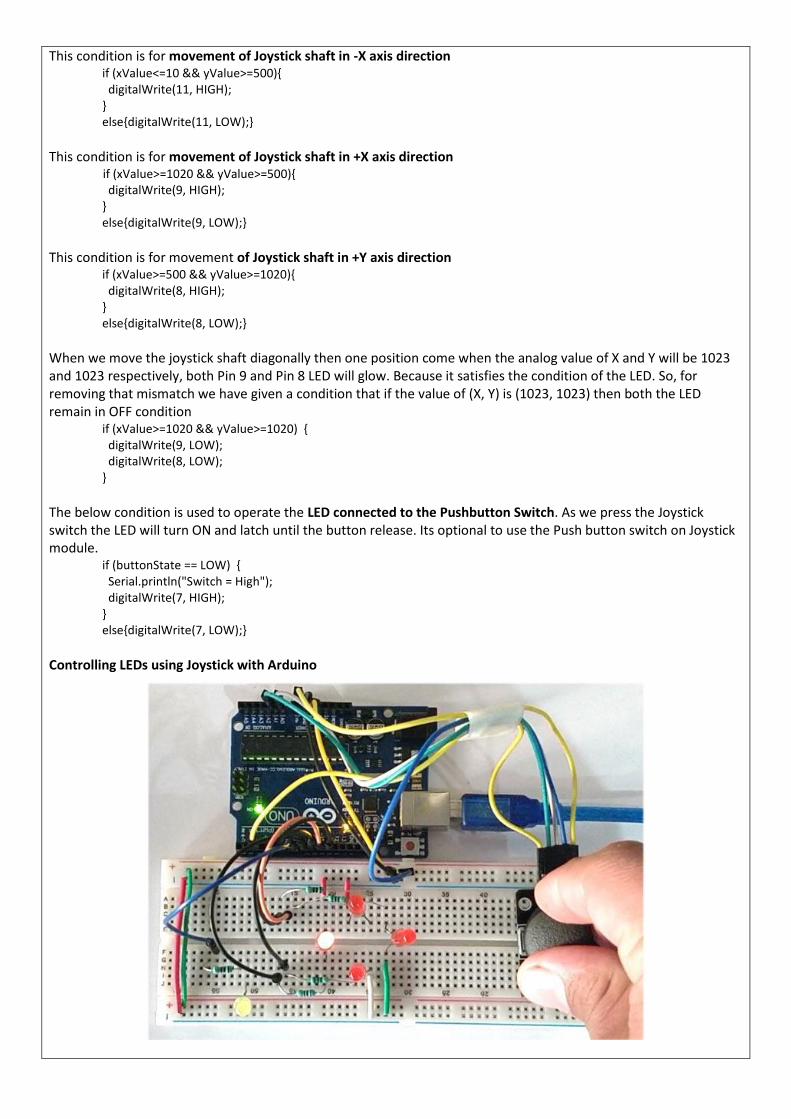
Controlling LEDs using Joystick with Arduino

After uploading the code to the Arduino and connect the components as per the circuit diagram, we can now control the LEDs with Joystick. We can turn ON the four LEDs in each direction as per the Joystick shaft movement. The Joystick is having two potentiometer inside it, one is for X-axis movement and another is for Y-axis movement. Each potentiometer is getting 5v from the Arduino. So as we move the joystick, the voltage value will change and the analog value at Analog pins A0 and A1 will also change. So, from the Arduino, we are reading the analog value for X and Y axis and turning ON the LEDs as per the axis movement of the Joystick. A push button switch on Joystick module is used to control the single LED in the circuit as shown in the video below. Code:
#define joyX A0 #define joyY A1 int button=2; int buttonState = 0; int buttonState1 = 0; void setup() { pinMode(7,OUTPUT); pinMode(button,INPUT); digitalWrite(button, HIGH); Serial.begin(9600); } void loop() { int xValue = analogRead(joyX); int yValue = analogRead(joyY); Serial.print(xValue); Serial.print("\t"); Serial.println(yValue); buttonState = digitalRead(button); Serial.println(buttonState); if (xValue>=0 && yValue<=10) { digitalWrite(10, HIGH); } else{digitalWrite(10, LOW);} if (xValue<=10 && yValue>=500) { digitalWrite(11, HIGH); } else{digitalWrite(11, LOW);} if (xValue>=1020 && yValue>=500) { digitalWrite(9, HIGH); } else{digitalWrite(9, LOW);} if (xValue>=500 && yValue>=1020) { digitalWrite(8, HIGH); } else{digitalWrite(8, LOW);} if (xValue>=1020 && yValue>=1020) { digitalWrite(9, LOW); digitalWrite(8, LOW); } if (buttonState == LOW) { Serial.println("Switch = High"); digitalWrite(7, HIGH); }

else{digitalWrite(7, LOW);} buttonState1 = digitalRead(7); Serial.println(buttonState1); delay(50); }
PNEUMATICA Realizzare i circuiti pneumatici relativi alle seguenti sequenze, scegliendo la tecnica di risoluzione più opportuna, tracciando diagramma di fase, analisi e definizione dei segnali, funzioni logiche di comando.
A+B-C+A-C-B+ A-B+(C+C-)B-A+ A-C-B+A+C+B- A+B+C+A-D+D-C-B+
--------------------------------------------------------


![imiliziani.files.wordpress.com · 12 1.6 Teorema del valor medio Data lafunzione y = f continua nell'intervallo [a; b] (quindi integrabile), esiste almeno un punto c interno all'intervallo](https://static.fdocumenti.com/doc/165x107/5ba17f3109d3f2616b8c7da3/-12-16-teorema-del-valor-medio-data-lafunzione-y-f-continua-nellintervallo.jpg)