CENTRALE DI ALLARME SENZA FILI CENTRALE D’ALARME … · sirena e (solo MOD. 5007 ......
40
1 SILENTRON - ITALIA COPYRIGHT SILENTRON DS5007XA030626GM CENTRALE DI ALLARME SENZA FILI CENTRALE D’ALARME SANS FIL Con possibilità di espansione filare Avec possibilite d’expansion filaire WIRELESS ALARM CONTROL PANEL FUNKALARMZENTRALE With possibility of hard-wired expansion Mit Möglichkeit der Erweiterung über Draht
Transcript of CENTRALE DI ALLARME SENZA FILI CENTRALE D’ALARME … · sirena e (solo MOD. 5007 ......

1SILENTRON - ITALIA COPYRIGHT SILENTRON DS5007XA030626GM
CENTRALE DI ALLARME SENZA FILI CENTRALE D’ALARME SANS FILCon possibilità di espansione filare Avec possibilite d’expansion filaire
WIRELESS ALARM CONTROL PANEL FUNKALARMZENTRALEWith possibility of hard-wired expansion Mit Möglichkeit der Erweiterung über Draht

2SILENTRON - ITALIA COPYRIGHT SILENTRON DS5007XA030626GM
DICHIARAZIONE DI CONFORMITA’: Con la presente SILENTRON s.r.l. dichiara che il materiale sopra descritto è conforme airequisiti essenziali ed alle altre disposizioni pertinenti stabilite dalla direttiva 1999/5/CE.
AVVERTENZE GENERALI - LEGGERE ATTENTAMENTE PRIMA DI OPERARE SULLE APPARECCHIATUREInstallazione: tutte le operazioni di installazione, manutenzione e/o modifica del sistema e suoi apparecchi devono essere effettuate dapersonale tecnico qualificato. Esse possono essere soggetta a norme tecniche specifiche che devono essere rispettate. Collegamenti elettrici:ogni collegamento elettrico senza eccezioni deve essere effettuato a regola d’arte fissando tutti i fili con fascette onde evitarne il distaccoaccidentale. Chiudere correttamente i contenitori degli apparecchi . Scollegare tutti i collegamenti elettrici superiori a 25V.prima di aprirecontenitori di apparecchi in funzione. Alimentazione esterna: 230 CA 50 Hz - collegarsi attraverso un sezionatore bipolare o una spinanormalizzata estraibile. Alimentazione a pile o batterie ricaricabili: sostituire le pile e/o batterie esclusivamente con modelli equivalenti,collocarle e collegarle rispettando la polarità indicata nelle istruzioni. Smaltire quelle esauste secondo le Norme vigenti, anche nel caso dirottamazione degli apparecchi, dai quali dovranno essere preventivamente estratte: in caso di fuoriuscita di liquido proteggere le mani conguanti al silicone. Pile al litio: attenzione ! pericolo di incendio e/o esplosione! La pila deve essere sostituita correttamente come sopra e soloda personale specializzato.Responsabilità: il fabbricante declina ogni responsabilità conseguente a errata installazione e/o manutenzione, errato uso e/o mancato usodegli apparecchi forniti. Garanzia: 3 anni, nei termini descritti sul Catalogo Generale, batterie e pile escluse.
DECLARATION DE CONFORMITE: Par la présente, SILENTRON s.r.l. déclare que le matériel indiqué ci-dessus est conforme auxexigences essentielles et aux autres dispositions pertinentes de la directive 1999/5/CE
AVERTISSEMENT - A LIRE AVEC ATTENTION AVANT D’UTILISER LES APPAREILSInstallation: toute opération d’installation, de manutention et/ou de modification du système et des appareils correspondants doit être effectuéepar du personnel technique qualifié. L’installation pourrait être soumise à des normes techniques spécifiques à respecter. Connexionsélectriques : toute connexion électrique doit impérativement être effectuée dans les règles de l’art, en liant bien tous les fils pour éviter undétachement accidentel. Bien refermer les boîtiers des appareils. Toute connexion électrique supérieure à 25 V doit être détachée avantd’ouvrir les boîtiers des appareils en fonction. Alimentation extérieure : 230 V CA 50 Hz - se brancher au travers d’un interrupteur de sécuritéou d’une fiche extractible. Alimentation à piles ou batteries rechargeables : remplacer les piles et/ou batteries seulement par des modèleséquivalents, les placer et les relier en respectant la polarité indiquée dans la notice. Recycler les piles remplacées selon les normes en vigueur,en cas d’appareil à recycler, les retirer auparavant. En cas de perte de liquide, protéger les mains par des gants en silicone. Piles lithium :Attention ! Danger d’incendie et/ou explosion ! La pile doit être remplacée correctement comme indiquée ci-dessus et seulement par dupersonnel qualifié. Responsabilité: le fabricant décline toute responsabilité concernant l’installation et/ou la manutention incorrecte, l’utilisationincorrecte et/ou la non-utilisation des appareils fournis. Garantie: trois ans, selon les Conditions Générales du Catalogue. Les batteries sonttoujours exclues.
STATEMENT OF CONFORMITY: Hereby, SILENTRON s.r.l., declares that the above mentioned equipment is in compliance withthe essential requirements and other relevant provisions of Directive 1999/5/EC.
WARNING - PLEASE READ CAREFULLY BEFORE USING THE EQUIPMENTInstallation : any installation, maintenance and/or modification of the system must be carried out by qualified personnel. There could be specialtechnical norms to be respected. Electrical connections : any electrical connection must be made according to the state of the art, all wiresmust be fixed and banded in order to avoid accidental detachment. Close properly the boxes of the devices. Disconnect all electrical connectionover 25 V before opening the boxes of the operating devices. Power Supply : 230 V AC 50 Hz - connection through security switch orextractable plug. Batteries : Take care! This equipment contains batteries. Replace the batteries by equivalent models only, place them andconnect them according to polarity as shown on them. Dispose of the exhausted batteries according to existing norms ; in case of wrecking, pullout batteries before destroying the equipment : in case of liquid dripping, wear silicone gloves to protect hands. Lithium batteries : Take Care !Danger of fire or explosion ! Lithium batteries must be properly replaced as shown above and only be qualified personnel.Responsibility : the manufacturer is not responsible for any consequence of improper installation and/or maintenance, improper and/or misseduse of the supplied units. Warranty: Three years warranty, submitted to conditions of General Catalogue - Battery excluded.
ÜBEREINSTIMMUNGSERKLÄRUNGHiermit erklärt SILENTRON s.r.l., dass das beschriebene Material den grundlegenden Anforderungen entspricht und mit denanderen diesbezüglichen, durch die Richtlinie 1999/5/CE festgelegten Vorschriften übereinstimmt.
ALLGEMEINE HINWEISE – VOR INBETRIEBNAHME DER GERÄTE BITTE SORGFÄLTIG LESENInstallation: Alle Installations- und Wartungsarbeiten, sowie Änderungen des Systems müssen von technisch qualifiziertem Fachpersonaldurchgeführt werden. Diese Geräte können besonderen technischen Normen unterliegen, die zu beachten sind.Elektrische Anschlüsse: Alle elektrischen Anschlüsse müssen ausnahmslos fachgerecht durchgeführt und die Drähte mit Kabelbindernbefestigt werden, um ein unbeabsichtigtes Loslösen zu vermeiden. Gehäuse der Geräte einwandfrei schließen. Vor Öffnen der Gehäuse von inBetrieb befindlichen Geräten, alle elektrischen Anschlüsse über 25V abstecken.Außenversorgung: 230V WS 50 Hz - Anschluß über zweipoligen Trennschalter oder einen genormten, herausziehbaren Stecker.Wiederaufladbare Batterien: Batterien ausschließlich durch gleichwertige Modelle ersetzen, Anbringung und Anschluß unter Beachtung der inden Anleitungen angegebenen Polung. Entsorgung der leeren Batterien gemäß den gültigen Normen, im Falle der Verschrottung der Gerätemüssen diese vorher herausgenommen werden. Bei Austreten von Flüssigkeit, Hände mit Silikonhandschuhen schützen.Haftung: Der Hersteller lehnt jegliche Verantwortung infolge von unsachgemäßer Installation und/oder Wartung, unsachgemäßer und/oder nichterfolgter Benutzung der gelieferten Geräte ab. Gewährleistung: 3 Jahre - siehe Bedingungen im Katalog – ausschließlich Batterien –ausschließlich Installation.
3SILENTRON - ITALIA COPYRIGHT SILENTRON DS5007XA030626GM
1a parte - FUNZIONI ED UTILIZZO DELLA CENTRALE
1 PRINCIPIO DI FUNZIONAMENTO
Il sistema EVOLUTION TOP è un insieme di apparecchiature funzionanti a pile e/o con fili di collegamento. Esse, opportunamente installate inun immobile, permettono la rilevazione di intrusioni non autorizzate, con conseguente attivazione di mezzi di allarme locali e segnalazioni adistanza. Dotati degli appositi accessori, i sistemi EVOLUTION sono in grado di rilevare o segnalare altri eventi pericolosi, quali malore -aggressioni o rapine - fughe di gas - incendi - allagamenti.
La centrale presiede al controllo dei rivelatori ed al comando dei mezzi di allarme sia cablati che senza fili. Essa è sempre in funzione pergarantire la protezione antisabotaggio del sistema ed il controllo degli allarmi “24 ore”.La centrale prevede la possibilità di tre “zone” di allarme inseribili singolarmente: in fase preventiva occorre distribuire i vari rivelatori nelle trezone secondo le esigenze dell’utente.
Nel progettare il sistema si deve tenere conto delle caratteristiche dei singoli componenti via radio o via cavo previsti, in funzione dei rischi diintrusione, quindi delle esigenze di utilizzo del cliente. Tutti i rivelatori e mezzi di allarme via cavo in commercio sono generalmente compatibilicon la centrale EVOLUTION TOP: elencarli sempre nel compilare la tabella impianto al fondo del presente manuale.
Fig 1: ESEMPIO DI INSTALLAZIONE CON SUDDIVISIONE IN ZONE:
zona A = protezione del piano terrenozona B = protezione del 1° pianozona C = protezione garage
2 COMPONENTI DEL SISTEMA EVOLUTION SENZA FILI
• 5030 SRA TOP sirena alta potenza per esterni, alimentata con pila litio e completa di lampeggiatore • 5034 SR – P sirena piezoelettrica per interni, alimentata con pile mezza torcia• 5011 PIR TOP rivelatore passivo di movimento (rivelatore di infrarossi) - area protetta superiore a 60mq.• 5015-16-17 SENSOR TOP sensore di apertura e di effrazione per porte e finestre, con morsetti per altri sensori esterni• 5020-21-22 SENSOR SLIM sensore di apertura e di effrazione per porte e finestre, con pila litio, 5 anni di autonomia• 5013 LASERBEAM barriera a raggi infrarossi per protezione di porte e finestre, anche in esterno (ved. istruzioni)• 5014 SILENT PIR rivelatore di infrarossi per impiego in esterni - protezione a ventaglio• 5024 P PCK 3P telecomando per inserire totalmente - inserire parzialmente le zone A+B - disinserire• 5023 P PCK 4P telecomando per inserire totalmente/parzialmente (A+B) - disinserire ed inviare allarme panico• 5023 PCK 4 telecomando per inserire/disinserire - inviare allarme panico + altro comando ausiliario• 5028 KEYPAD tastiera a codice per inserimento totale/parziale e disinserimento, con pulsante panico• 5026 PA WLR segnalatore esterno di stato impianto, presenza rete ed allarme• 5007 EVOLUTION TOP centrale 96 rivelatori radio + altri via filo, divisi su 3 zone + allarmi tecnici e panico, con alimentatore,
sirena e (solo MOD. 5007 C) comunicatore digitale di eventi integrato
3 FUNZIONI DELLA CENTRALE EVOLUTION TOP
• estrema semplicità di programmazione e controllo degli eventi• 96 canali - 96 rivelatori programmabili, singolarmente identificati su display• possibilità di programmazione in “and” di 2 rivelatori per canale - possibilità di ritardare l’allarme di ogni rivelatore• inserimento totale e parziale + disinserimento tramite telecomandi PCK e PCK-P. Sono programmabili fino a 32 PCK• inserimento totale e parziale + disinserimento tramite una o più tastiere a codice numerico Keypad - max 32 codici diversi• possibilità di inserimento / disinserimento generale con chiave elettronica o elettromeccanica via cavo• 3 ingressi NC per rivelatori di allarme via cavo• visualizzazione tramite spie led e display di tutte le funzioni di ogni singolo rivelatore• visualizzazione e memorizzazione degli ultimi 50 eventi in successione cronologica• uscite elettriche per mezzi di allarme e dispositivi di telesorveglianza• allarmi sonori diversificati per intrusione - panico - rapina• allarmi tecnici (fumo - gas - allagamento ecc.) ottenibili collegando un SENSOR Top a rivelatori specifici• allarme manomissione per tutti i componenti del sistema (telecomandi esclusi)• allarme supervisione in caso di pila scarica e/o guasto del rivelatore• allarme scanner in caso di disturbi radio o tentativi di blocco delle radiotrasmissioni del sistema• possibilità di test di ogni singolo componente del sistema• modello /C con trasmettitore telefonico integrato ad 8 numeri (protocolli Ademco/Scantronic e Contact-Id)• modello /C con possibilità di chiamate telefoniche di allarme a privati
4SILENTRON - ITALIA COPYRIGHT SILENTRON DS5007XA030626GM
3.1 FUNZIONI AGGIUNTIVE INTEGRATE NEL SISTEMA EVOLUTION (senza posa di cavi)
COMANDO DI CARICHI ELETTRICI DA TELECOMANDI E/O DA TASTIEREI telecomandi PCK e le tastiere Keypad possono comandare automazioni domotiche anche già esistenti quali cancelli e/o tapparelle motorizzateed anche accendere/spegnere luci o altre utenze elettriche fino a 8A a 230V, attraverso i ricevitori senza fili RX 1 e RX 2. Ogni utenza elettricaasservita ad un ricevitore Silentron può essere comandata anche dall’esterno via telefono, tramite l’apparecchio cod. 5160 Multiactiva. Chiedereinformazioni in merito al vostro installatore o consultare direttamente il ns. sito www.silentron.it.
ACCENSIONE LUCI AUTOMATICAIn ogni ambiente ove sia installato un rivelatore Silentron si può far accendere automaticamente la luce tramite uno o più ricevitori Silentron RX2collegati agli interruttori esistenti. La luce si accenderà solo se è buio e per un tempo regolabile ogni volta che il rilevatore sentirà una presenzain movimento, indipendentemente dal fatto che l’impianto sia o meno inserito.Oltre alla comodità dell’automatismo si ottiene anche un maggior effetto deterrente del sistema di allarme in caso di intrusioni non desiderate.
PROTEZIONE ANTIAGGRESSIONEE’ possibile realizzare protezioni in esterno attraverso gli appositi rivelatori ( 5013 - 5014 ). In questo caso i rivelatori devono essere sempreprogrammati in AND (vedere 16.2). ATTENZIONE: questo tipo di protezione è inevitabilmente soggetto ad allarmi impropri, che soloun’accuratissima installazione può ridurre al minimo.
4 INDICAZIONI OTTICHE DELLA CENTRALE EVOLUTION TOP ( fig. 2 )
Ogni funzione del sistema viene chiaramente indicata dalla centrale, tramite spie led e display numerico. Il significato delle indicazioni èdescritto al paragrafo 10.
5 INSERIMENTO TOTALE DEL SISTEMA
La centrale si inserisce premendo il tasto rosso di un telecomando . Si accendono tutti i led di zona, ad indicare tutte le zone inserite, e si hauna segnalazione acustica (BEP - BEP - BEP): Il sistema è attivo dopo 60”. La segnalazione può essere ripetuta da eventuali sireneL’inserimento può essere effettuato anche da una tastiera, digitando il codice di 4 cifre e successivamente il tasto rosso: si ottiene la stessasegnalazione di conferma. A seguito di un inserimento si possono avere segnalazioni di funzione o anomalia: vedere paragrafo 10“segnalazioni”.
6 INSERIMENTO PARZIALE DEL SISTEMA ( fig. 3)
a) Con un telecomando tipo 5023P o 5024P si inseriscono immediatamente le sole zone A + B premendo il tasto bianco. Il sistema è attivodopo 60”.
b) L’inserimento parziale può essere effettuato anche da una o più tastiere, digitando il codice di 4 cifre, poi i tasti A-B-C delle zone che sidesidera escludere: sulla tastiera si spegneranno i led relativi. Premendo successivamente il tasto rosso si conferma l’inserimento delle zonedesiderate. Il sistema è attivo dopo 60”.
La centrale confermerà l’inserimento con una segnalazione acustica (BEEEEP continuo) e visualizzerà, durante il tempo di uscita, le zoneinserite con l’accensione dei relativi led A-B-C. A seguito di un inserimento parziale si possono avere segnalazioni di anomalia: vedereparagrafo 10 “segnalazioni”.
7 DISINSERIMENTO DEL SISTEMA (sempre totale)
La centrale si disinserisce premendo il tasto verde di un telecomando. Si ha una segnalazione acustica della centrale (BEP), ripetuta daeventuali sirene. Il disinserimento può essere effettuato anche da una tastiera, digitando il codice di 4 cifre e successivamente il tasto verde: siottiene la stessa segnalazione di conferma. A seguito di un disinserimento si possono avere segnalazioni di funzione o anomalia: vedereparagrafo 10 “segnalazioni”.
8 ALLARME INTRUSIONE
Ogni rivelatore sollecitato trasmette un segnale di allarme alla centrale: se essa è inserita si ha un ciclo di allarme di tre minuti.In caso di nuova intrusione, la centrale consente fino a 3 cicli di allarme ripetuti per ogni rivelatore e fino ad un massimo di 8 cicli di allarme intotale per ogni periodo di inserimento, dopodichè si blocca per salvaguardare la quiete pubblica.I rivelatori programmati per funzionare con “ritardo ingresso” danno allarme con un ritardo di 30”, onde consentire l’accesso ai locali protettiper eventuali manovre con la tastiera: durante questo tempo la centrale emette ripetuti BEP di avvertimento.Ogni allarme viene memorizzato dalle spie del canale relativo e segnalato con successivi BEP al disinserimento del sistema.Un comando di “disinserimento” blocca eventuali allarmi in corso.
9 ALTRE SITUAZIONI DI ALLARME ( fig. 4 )
1) Allarme panico: con un telecomando PCK programmato opportunamente sulla zona “PANICO” si possono attivare immediatamente lesole sirene esterne, premendo il pulsante dedicato. E’ disponibile anche una uscita elettrica (morsetto MZ PAN)
2) Allarme rapina: un eventuale combinatore via radio può essere comandato direttamente dal telecomando. Disponendo di un combinatoretelefonico collegato via cavo (5140 - 5145 - 5146 - 5240) il comando è disponibile sul morsetto MZ RAP: in questo caso il tasto dedicato deltelecomando va programmato sulla zona “RAPINA”.

5SILENTRON - ITALIA COPYRIGHT SILENTRON DS5007XA030626GM
3) Allarmi tecnici: eventuali SENSOR TOP dotati di apposito rivelatore (gas - fumo - allagamento ecc.) opportunamente programmati sullazona “ALL. TECNICI” danno luogo ad allarme a bassa intensità. E’ disponibile anche una uscita elettrica (morsetto MZ TEC)
4) Allarmi manomissione
Con centrale disinserita o parzialmente inserita, la manomissione di un apparecchio provoca il suono della sirena interna per 3 minuti ma abassa intensità (disponibile anche una uscita elettrica - morsetto MZ TMP). Con centrale inserita provoca l’attivazione di tutte le sirene per 3minuti. La manomissione delle sirene provoca l’allarme delle stesse senza altra segnalazione, se non protette con un SENSOR SLIM interno,programmato su una zona 24 ore (ad esempio Panico).
5) Allarme disturbi radio e supervisione
Con centrale inserita, la ricezione di disturbi radio tali da limitare la funzionalità del sistema provoca allarme della sirena interna della centrale.Attenzione: la funzione deve essere abilitata in fase di installazione. E’ disponibile anche una uscita elettrica (morsetto MZ VIS), sempre attivaanche con funzione disabilitata.
La mancata ricezione dei segnali di supervisione dei rivelatori provoca segnalazione ottica ed acustica al momento dell’inserimento o deldisinserimento della centrale (vedere “segnalazioni”). Attenzione: la funzione deve essere abilitata in fase di installazione. E’ disponibile ancheuna uscita elettrica (morsetto MZ VIS - in comune con la funzione precedente), sempre attiva anche con funzione disabilitata.
10 SEGNALAZIONI OTTICO - ACUSTICHE DELLA CENTRALE
LA MEMORIA EVENTI
EVOLUTION memorizza gli ultimi 50 eventi occorsi al sistema, cioè ogni inserimento/disinserimento, ogni allarme ed ogni anomalia. Dettieventi possono essere richiamati e visualizzati, a partire dall’ultimo verificatosi ed andando indietro nel tempo. Ogni evento successivo al50esimo cancella automaticamente quello avvenuto più lontano nel tempo. NOTA: per azzerare la memoria eventi è sufficiente entrare inTEST (par. 11)
LETTURA DELLA MEMORIA EVENTI
Quando la centrale è disinserita ed il display è spento si può leggere la memoria eventi: basta premere il tasto verde del telecomando,guardando il riquadro spie della centrale: lampeggeranno i due puntini sul riquadro e verrà visualizzato l’ultimo evento occorso, ove la spiaaccesa identifica il tipo di evento, che sarà relativo al rivelatore indicato dal numero sul display. Se l’evento si riferisce alla centrale stessa verràvisualizzato “CC”. Premendo ancora il tasto verde del telecomando verrà visualizzato il penultimo evento e così via fino al 50esimo. La centralenon indica ora e data, ma solo la successione temporale.
ESEMPIO DI EVENTI
avvenuto allarme del rivelatore n. 11appartenente alla zona A
batteria scarica nel rivelatore 11 (zona A)
SEGNALAZIONE DI NUOVO EVENTO O ANOMALIA - serie di BEP dopo inserimento o disinserimento.
Ogni nuovo “evento” viene memorizzato dalla centrale e segnalato alla prima variazione di stato (da “centrale inserita” a “centrale disinserita” oviceversa), con una serie di BEP-BEP-BEP-BEP in aggiunta a quelli di inserimento o di disinserimento. L’utente non deve e non può ignoraretale segnalazione, poichè indica un’avvenuto allarme o un anomalia del sistema. E’ indispensabile quindi leggere la memoria eventi perverificare e provvedere.
ATTENZIONE: Si esce automaticamente dalla fase di lettura della memoria dopo 60 secondi senza interrogazioni, oppure inserendo lacentrale, oppure raggiungendo l’ultimo evento memorizzato.

6SILENTRON - ITALIA COPYRIGHT SILENTRON DS5007XA030626GM
SEGNALAZIONI DELLA CENTRALE E PROVVEDIMENTI CONSEGUENTI
EVENTO LED FISSO LED LAMP DESCRIZIONEA B C SI zone di allarme inseritePANICO SI allarme panico (via PCK si provoca il suono immediato delle sirene)ALLARMI TECNICI SI allarme fumo, gas, allagamento, secondo i rivelatori utilizzati e programmatiDISPLAY NUMERO PERIFERICA identificazione numerica del singolo rivelatoreTEST SI centrale in TEST per provare il sistema senza attivare le sirene.PROGRAMMAZ. SI centrale in PROGRAMMAZIONERITARDO INGRESSO SI il rivelatore indicato dal numero sul display dà allarme con un ritardo di 30 sec.RIVELATORE ESCLUSO SI il rivelatore indicato dal numero sul display è stato escluso (non è operativo).DOPPIO RIVELATORE SI vi sono 2 rivelatori che operano insieme nell’area indicata dal numero sul display.
PORTA APERTA SI E' stato lasciato aperto un infisso protetto: potete chiuderlo o lasciare così;ovviamente se l’infisso rimane aperto non vi è protezione in quel punto.
MEMORIA ALLARME SIdurante l’ultimo periodo di inserimento il rivelatore indicato dal display hagenerato un allarme: se non vi è stata intrusione o errore avvertire il serviziotecnico.
MANOMISSIONE SIil rivelatore indicato è stato manomesso: questo evento genera immediatamenteallarme (a bassa intensità con centrale disinserita): verificare ed avvertire ilservizio tecnico.
BATTERIA SI il rivelatore indicato necessita di sostituzione della batteria: avete diversi giorni diautonomia residua. E’ comunque bene far sostituire la batteria al più presto.
ANOMALIA R.F SI
la centrale non ha ricevuto correttamente i segnali di controllo (supervisione) delrivelatore indicato. Effettuarne un TEST: se positivo il disturbo potrebbe essereoccasionale, quindi ininfluente. Se la segnalazione si ripete spesso il rivelatore èstato installato al limite della portata o non correttamente, quindi deve esserespostato. Se il rivelatore non funziona escluderlo ed avvertire il servizio tecnico.
SEGNALAZIONI RELATIVE ALLA CENTRALE E COSA FARE DI CONSEGUENZA:
display CC l’indicazione CC del display indica che l’evento evidenziato dal led è relativo alla centrale stessa: nel caso sia acceso il led“batteria” occorre provvedere immediatamente a far sostituire la batteria della centrale.
display on l’indicazione ON appare quando la centrale viene inserita; essa scompare dopo 60 secondi, al termine del tempo di uscita.
display - - l’indicazione - - appare quando la centrale viene disinserita; essa scompare dopo 60 secondi,
11 TEST DEL SISTEMA
Per provare il sistema senza attivare sirene e combinatori telefonici occorre usare un telecomando PCK-P come segue:
tasti rosso e verde: premuti insieme per 1 secondo circa inseriscono lo stato di TEST: si accende la spia TEST.tasti rosso e verde: in stato di TEST, premuti insieme per 1 secondo circa escludono il rivelatore selezionatotasti rosso e verde: in stato di TEST, premuti insieme per 10 secondi circa cancellano tutti i telecomandi programmatitasto verde: vedere "Lettura della memoria eventi"tasto bianco: selezione della posizione (numeri da 1 a 96) del rivelatore - ad ogni pressione avanza di un numero.tasto rosso: fine TEST e ritorno al normale funzionamento
Nello stato di TEST le sirene sono bloccate: alcuni modelli senza fili confermano il blocco con ripetuti BEEP (vedere istruzioni specifiche): ciò èutile anche per cambiarne le batterie senza generare allarme tamper.Provare la funzionalità del sistema sollecitando man mano ogni rivelatore: si avrà un BEEP e l’accensione temporanea del numero relativo adogni rivelatore andato in allarme. Questi allarmi restano memorizzati (fino a 50) e sono quindi verificabili interrogando la memoria eventi (par.10) dopo essere usciti dallo stato di TEST. E’ consigliabile effettuare almeno un test ogni anno.
ATTENZIONE: per provare correttamente i rivelatori volumetrici 5011 PIR TOP e 5014 SILENT PIR occorre lasciare i locali protetti vuoti dapersone e animali per almeno 3 minuti prima di provocare un allarme entrando nell’area. Volendo verificare l’area protetta occorre mettere ognirivelatore in stato di TEST.(vedere sue istruzioni).
11.1 ESCLUSIONE DI RIVELATORI
In caso di guasto di un rivelatore è possibile escluderlo temporaneamente dal sistema. Con la centrale in TEST, cercare la posizione delrivelatore premendo ripetutamente il tasto bianco del telecomando. Localizzato il rivelatore, premere insieme i tasti rosso-verde deltelecomando: l’esclusione è confermata e visualizzata dal led RIVEL. ESCLUSO. Ripetendo la manovra si riporta il rivelatore escluso incondizioni di normale funzionamento.

7SILENTRON - ITALIA COPYRIGHT SILENTRON DS5007XA030626GM
12 SEGNALAZIONI DI APPARECCHIATURE DIVERSE DALLA CENTRALE
Alcune apparecchiature del sistema forniscono segnalazioni indipendenti rispetto alla centrale, ad ulteriore conferma.Vedere anche le istruzioni specifiche dei singoli apparecchi:
5026 PA TOPspia rossa accesa = sistema inseritospia gialla lampegg. = avvenuto allarmespia verde accesa = regolare presenza di tensione di rete
5030 SRA TOP 5034 SR-PBEP BEP BEP all’inserimento della centrale - BEP al disinserimento della centraleBEEEEEP prolungato per 30 secondi = pila scarica - sostituire le pile entro 48 ore
RIVELATORI RADIO DI VARIO TIPOTutti i rivelatori segnalano anche localmente ( BEEP ad ogni allarme ) la necessità di cambiare la pila (entro alcuni giorni)).
2a parte - INSTALLAZIONE E PROGRAMMAZIONI
13 CARATTERISTICHE TECNICHE DELLA CENTRALE 5007 EVOLUTION TOP (vedere anche 13.1 e schema elettrico):
Allarmi intrusione via radio: fino a 96 rivelatori programmabili immediati o ritardati su 3 zone di inserimento (A-B-C) oppure sulle zone 24ore Panico, Rapina, Allarme Tecnico.
via filo: 3 linee NC identificate con i numeri 99 A (zona A) - 99 B (zona B) - 99 C (zona C).
Allarme manomissione via radio: - Ricezione del segnale manomissione da ogni singolo rivelatore- Ricezione dei segnali di “esistenza in vita” e di pila scarica (SUPERVISIONE).
via filo: - linea Tamper NC, che comprende la protezione apertura/strappo della centrale.
Allarme Anomalia R.F. controllo della frequenza radio con segnalazione di disturbi ed occupazione della frequenza
Temporizzazioni : inserimento ritardato di 60 secondi - tempo allarme 3 minuti - ritardo ingresso 30 secondi solo sui rivelatori così programmati.
Visualizzazioni: 16 led di funzione + identificazione numerica del rivelatore tramite display 2 digit.
Sirena interna: con funzione di allarme 106 db - con funzione di segnalazione ad intensità regolabile
Comunicatore digitale (solo modello 5007C) : trasmissione ad 8 numeri telefonici dei protocolli Ademco-Scantronic e/o Contact ID + segnalisonori identificabili dall’utente. Programmazione via PC. Vedere istruzioni specifiche.
Comandi: telecomandi mod. 5023P PCK 4P (4 tasti) e 5024P PCK 3P (3 tasti - 1 pz. fornito a corredo).
RICETRASMISSIONI RADIO: digitali, codificate in fabbrica e gestite in autoapprendimento da microprocessore - frequenza e potenza a normadi legge - Portata radio: 100m in aria libera ed in assenza totale di disturbi di fondo sulla banda - Essa può subire sensibili riduzioni in internicausa la posizione degli apparecchi in relazione con la struttura dei locali e/o a causa di disturbi radio sulla banda. Occorre sempre verificareche le portate radio siano sufficienti prima della installazione definitiva.
DIMENSIONI: 310x214x91mm PESO: 2,6 Kg BOX: ABS bianco/grigio TEMPERATURA: operativa/stoccaggio -20°+50°C
13.1 CARATTERISTICHE TECNICHE DEI COLLEGAMENTI VIA CAVO
Alimentazione 230V CA: collegare alla rete soltanto al termine dell’installazione effettuare programmazione e prove con la sola batteria
Assorbimento: scheda centrale 20 mA in stand-by. Per calcolo autonomia considerare capacita della batteria assorbimento scheda e tutti icarichi esterni collegati via filo
Erogazione stabilizzata in CC: max 600mA a 13,8V con protezioni elettroniche (ved. schema) - batteria prevista PB 12V 7Ah standard (labatteria è obbligatoria e non fornita)
Punti di regolazione RESET pulsante di reset totale delle programmazioni(vedi schema elettrico) Scanner attivazione/disattivazione del controllo disturbi radio e supervisione
BZ regolazione intensità BEEP di segnalazioneJP 4 con il jumper in questa posizione si ha il funzionamento normale del ricevitoreJP 5 spostando il jumper in questa posizione si attiva l’attenuatore del ricevitore
per fare le prove di portata radioIN - OUT collegamenti su morsettiera per linea telefonica e telefono + plug per linea telefonica + plug per
programmazione con PC per il modello 5007/C
COLLEGAMENTI: vedere schema al fondo
8SILENTRON - ITALIA COPYRIGHT SILENTRON DS5007XA030626GM
14 PRECAUZIONI DA OSSERVARE PER UNA CORRETTA INSTALLAZIONE (vedere figura 1)
Ogni installazione deve tenere conto delle diverse situazioni ambientali, quindi richiede professionalita’ ed attenzione. Errori in fase diinstallazione possono causare malfunzionamenti del sistema, non imputabili agli apparecchi.
Prima dell’installazione occorre definire il tipo e la posizione dei rivelatori con e senza fili previsti, nonchè la loro suddivisione nelle 3 zone ai finidell’inserimento parziale, quindi occorre compilare la tabella all’ultima pagina. I rivelatori o telecomandi con funzioni speciali (24 h) dovrannoessere programmati sui canali appositi. La portata dei telecomandi può variare in funzione della posizione e del modo di tenerli in mano durantela trasmissione: verificare le situazioni più favorevoli. Tutti gli ostacoli fisici causano perdita di portata radio. Per controllare la potenza delsegnale ricevuto spostare il jumper dalla posizione JP4 alla posizione JP5 e verificare la corretta ricezione dei segnali. E’ consigliabile utilizzarelo strumento FIELD METER, ponendolo nel luogo di installazione della centrale e verificando che i segnali ricevuti siano almeno nella fasciagialla (fig. 5). In assenza di trasmissioni del sistema, il disturbo di fondo segnalato dal FIELD METER non deve superare la zona verde.
Parte via cavo: prevedere il passaggio dei cavi per sirene, combinatori e quant’altro. Ogni apparecchio deve essere collegato ai morsetti comeda schema. Calcolare l’assorbimento di corrente degli apparecchi via cavo e verificare che il totale sia compatibile con la capacità di erogazionedell’alimentatore (1A max carico di punta - 700mA max continui)
15 POSIZIONAMENTO E FISSAGGIO DELLA CENTRALE (vedere figura 6)
La centrale deve essere in posizione “centrale” rispetto a rivelatori e sirene, per garantire la buona ricezione radio. Essa può essere collocatadentro mobili non metallici oppure fissata al muro, tenendo conto dei seguenti fattori:
• buona ricezione e trasmissione radio (Field meter)• comodità dei collegamenti via filo previsti• collocazione in area protetta almeno da un rivelatore volumetrico• udibilità della sirena interna e delle segnalazioni sonore (intensità regolabile)• necessità di visualizzare le spie led ed il display
NOTA: la corretta posizione degli apparecchi deve essere privilegiata rispetto ad eventuali vincoli estetici che possono pregiudicareil buon funzionamento del sistema.
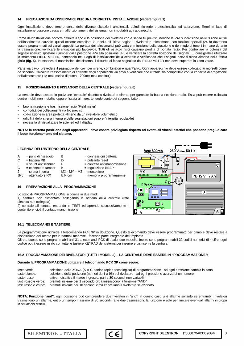
LEGENDA DELL’INTERNO DELLA CENTRALE
A = punti di fissaggio B = connessioni batteriaC = batteria PB D = pulsante resetE = shunt antiscanner F = contatto antimanomissioneG = connettore tamper K = regolazione BEEPJ = sirena interna MX - MY – MZ = morsettiereJP5 = attenuatore RX E Prom = memoria programmazione
16 PREPARAZIONE ALLA PROGRAMMAZIONE
Lo stato di PROGRAMMAZIONE si ottiene in due modi:1) centrale non alimentata: collegando la batteria della centrale (reteelettrica non collegata)2) centrale alimentata: entrando in TEST ed aprendo successivamente ilcontenitore, cioè il contatto manomissione
16.1 TELECOMANDI E TASTIERE
La programmazione richiede il telecomando PCK 3P in dotazione. Questo telecomando deve essere programmato per primo e deve restare adisposizione dell’utente per le normali manovre, facendo parte integrante dell’impiantoOltre a questo sono programmabili altri 31 telecomandi PCK di qualunque modello. Inoltre sono programmabili 32 codici numerici di 4 cifre: ognicodice potrà essere usato con tutte le tastiere KEYPAD del sistema per inserire e disinserire la centrale.
16.2 PROGRAMMAZIONE DEI RIVELATORI (TUTTI I MODELLI) – LA CENTRALE DEVE ESSERE IN “PROGRAMMAZIONE”:
Durante la PROGRAMMAZIONE utilizzare il telecomando PCK 3P come segue:
tasto verde: selezione della ZONA (A-B-C-panico-rapina-tecnologica) di programmazione - ad ogni pressione cambia la zonatasto bianco: selezione della posizione (numeri da 1 a 96) del rivelatore - ad ogni pressione avanza di un numero.tasto rosso: attiva - disattiva il ritardo ingresso, pari a 30 secondi non variabili.tasti rosso e verde: premuti insieme per 1 secondo circa inseriscono la funzione "AND"tasti rosso e verde: premuti insieme per 10 secondi circa cancellano il rivelatore selezionato.
NOTA: Funzione “and”: ogni posizione può comprendere due rivelatori in “and”: in questo caso vi è allarme soltanto se entrambi i rivelatoritrasmettono un allarme, entro un tempo massimo di 30 secondi fra le due trasmissioni: la funzione è utile per limitare eventuali allarmi impropriin situazioni difficili.

9SILENTRON - ITALIA COPYRIGHT SILENTRON DS5007XA030626GM
17 SEQUENZA DI PROGRAMMAZIONE
1 Attivare l’ antiscanner chiudendo lo shunt: la sirena segnalerà eventuali disturbi radio già durante la programmazione e successivamente.2 Collegare una batteria al piombo Pb 12V 7 Ah (carica enon fornita) ed attendere 20 secondi per la stabilizzazione del ricevitore radio..3 Premere il pulsante di RESET per cancellare eventuali programmazioni di prova ( BEEEEEP)4 La centrale presenta il led PROGR. - TEST lampeggiante, ed è pronta alla PROGRAMMAZIONE5 Regolare l’intensità del BEEP a piacere6 Programmare il telecomando fornito con la centrale, premendo insieme i pulsanti rosso e verde fino ad udire il suono di conferma (BEP)7 Programmare gli altri telecomandi (qualunque modello) premendo insieme i pulsanti rosso e verde come sopra8 Programmare eventuali codici da tastiera: digitare 4 cifre, poi premere insieme i tasti rosso e verde fino a udire il BEP9 Selezionare col tasto verde la zona ove si vuole programmare il primo rivelatore (esempio A: sul display appare A1). Volendo inserire il
ritardo di ingresso premere il tasto rosso del telecomando (led RITARDO INGR.). Volendo inserire la funzione “and” premere insieme i tastirosso e verde (led DOPPIO RIVEL.).
10 Prendere nota del numero assegnato e programmare il rivelatore inserendovi la pila: un BEP della centrale conferma ed il display passa allaposizione successiva. Se si è prevista la funzione “and” il numero sul display lampeggia: programmare anche il secondo rivelatore.
11 Programmare gli altri rivelatori come sopra (punti 9 e 10): volendo assegnare posizioni precise, non in sequenza, ricercarle premendo iltasto bianco del PCK
12 Programmare, premendolo 10 secondi, il pulsante giallo o blu dei telecomandi sulla zona PANICO, volendo attivare la relativa funzione 9.113 Programmare, premendolo 10 secondi, il pulsante giallo o blu dei telecomandi sulla zona RAPINA, volendo attivare la relativa funzione 9.214 Programmare eventuali rivelatori di allarme tecnico sulla zona ALL. TECNICI - funzione 9.3
La programmazione effettuata permane nella scheda estraibile EProm anche scollegando la batteria e si cancella totalmente solo premendoRESET. La scheda estraibile può essere trasferita in caso di sostituzione della centrale.Terminata la programmazione della parte radio effettuare prove di corretta ricezione, inserendo il jumper nella posizione JP5 (vedere schema).Eliminare l’attenuatore RX riposizionando il jumper in posizione JP4 e fissare la centrale al muro solo dopo esito positivo. Procedere quindi alcollegamento di eventuali rivelatori e/o mezzi di allarme via filo (vedere schema).
17.1 APPARECCHI VIA FILO
I contatti di allarme dei rivelatori cablati si collegano agli ingressi A - B - C e sono automaticamente destinati alle posizioni A99 - B99 - C99. Gliingressi non utilizzati possono rimanere aperti. Rivelatori e sirene via filo devono essere collegati come descritto al paragrafo 13.1.
Verificare i collegamenti e chiudere la centrale, avvitando la vite del coperchio (chiusura elettrica del pulsante tamper): ciò comporta ilpassaggio automatico dalla condizione di PROGRAMMAZIONE a quella di TEST.
L’allarme dei rivelatori via filo (apertura della linea) provoca l’accensione del led di zona e del numero 99 sul display . Sirene, combinatori esegnalatori via filo vanno provati successivamente, con la centrale in condizione di “normale funzionamento”.
17.2 COLLEGAMENTO ALLA RETE ELETTRICA
Il collegamento alla rete deve essere effettuato con cavo 2x1mmq a doppio isolamenrto,utilizzando l’apposita morsettiera estraibile con fusibile incorporato (500mA). Il cavo deveessere bloccato nei fermi previsti, onde evitare distacchi accidentali e terminare con unaspina inseribile in una presa elettrica. Al termine del collegamento chiudere il vano dellamorsettiera 230V con l’apposito coperchio, chiudere la centrale e, successivamente,connettere la spina alla presa: il led di rete acceso indica la presenza di corrente ed ilfunzionamento dell’alimentatore.
18 PROGRAMMAZIONE DEI MEZZI DI ALLARME
• Predisporre le sirene ed i combinatori telefonici ad apprendere il codice della centrale (vedere istruzioni specifiche).• Inserire la centrale, poi disinserirla attraverso una temporanea connessione fra i morsetti KEY e GND, ed attendere conferma sonora
(sirene = sei BEP consecutivi)
19 MODIFICHE O VARIANTI AL SISTEMA - in ogni caso occorre portare la centrale in posizione TEST
Aggiunta di telecomandi PCK e codici da tastiera: operazione effettuabile dall’utente come descritto al punto 17 (7)
Cancellazione dei PCK (occorre cancellarli tutti, riprogrammando poi quelli utili): premere insieme per 10 secondi i pulsanti rosso e verdedi un PCK programmato: si ha 1 lungo BEEEEEEP a cancellazione avvenuta.
Cancellazione del singolo codice da tastiera: passare in modalità TEST, quindi digitare il codice e poi premere rosso e verde per 10 secondi,fino al BEEEEEEP finale.
Aggiunta/eliminazione di rivelatori: aprendo la centrale si accede alla PROGRAMMAZIONE, quindi si può modificare posizione ecaratteristiche dei rivelatori. Per modifiche del ritardo ingresso procedere come durante la programmazione (par. 16.2): ricerca posizione contasto bianco del telecomando e modifica con il tasto rosso. Per modifiche alla funzione “and”, i sensori vanno cancellati. Per eliminare unrivelatore ricercare la posizione e premere i tasti rosso e verde insieme per 10 secondi (Beeeeep di conferma eliminazione).
Sostituzione della centrale: in caso di guasto è possibile sostituire la centrale con un'altra uguale salvando tutta la programmazionedell'impianto. Occorre togliere alimentazione alla centrale, estrarre la Eprom (ved. schema) ed inserirla nella nuova centrale.

10SILENTRON - ITALIA COPYRIGHT SILENTRON DS5007XA030626GM
première partie - FONCTIONNEMENT ET UTILISATION USAGER
1 FONCTIONNEMENT DU SYSTEME
Le système EVOLUTION TOP est composé de plusieurs appareils sans et/ou avec fil. Installé correctement, l’ensemble du système permet ladétection d’intrusions non-autorisées et le déclenchement d’avertisseurs d’alarme. Avec les accessoires disponibles, EVOLUTION TOP peutdétecter aussi d’autres événements dangereux tels que l’agression, le malaise, la fuite de gaz, l’incendie et les fuites d’eau.La centrale EVOLUTION TOP intègre la gestion des détecteurs et des avertisseurs d’alarmes sans fil et filaires. Elle est toujours en fonctionpour garantir l’autoprotection du système et le déclenchement des alarmes 24h.A l’aide de télécommandes ou/et de claviers, la centrale rend possible la mise en marche séparée des trois groupes de zones : pour cela, il estnécessaire de prédisposer les détecteurs dans les trois groupes, selon les exigences du client.
Pour une installation correcte, bien évaluer les caractéristiques des unités à installer, les exigences du client, mais également les risquesd’intrusion. Tout détecteur, sirène et transmetteur téléphonique filaire disponible sur le marché peut être utilisé avec EVOLUTION TOP. Avantd’installer les unités du système, il est fort conseillé de remplir le tableau final.
Fig. 1: exemple d’installation avec répartition en groupe
groupe A protection rez-de-chausséegroupe B protection premier étagegroupe C protection garage
2 COMPOSANTS DU SYSTEME
• 5030 SRA TOP Sirène extérieure de forte puissance, avec flash clignotant et bloc pile au lithium• 5034 SR - P Sirène intérieure de forte puissance, alimentée par piles alcalines• 5011 PIR TOP Détecteur passif de mouvement à l’infrarouge - surface protégée : plus de 60m².• 5015-16-17 SENSOR TOP Détecteur d’ouverture et choc pour huisseries, avec borne pour des détecteurs filaires• 5020-21-22 SENSOR Slim Détecteur d’ouverture et choc pour huisseries, avec 5 ans de fonctionnement (lithium)• 5013 LASERBEAM barrière infrarouge pour protection de portes et fenêtres, tant à l’intérieur qu’à l’extérieur• 5014 SILENT PIR détecteur infrarouge pour l’utilisation à l’extérieur (ou en intérieur) : protection à rideau ou éventail• 5024 P PCK 3P Télécommande marche-arrêt totale + marche partielle (groupes A + B seulement)• 5023 P PCK 4P Télécommande marche-arrêt totale + marche partielle (groupes A et B) + service panique ou additionnel• 5023 PCK 4 Télécommande marche-arrêt totale + panique + service additionnel• 5028 KEYPAD Clavier déporté pour marche-arrêt + marche partielle + touche panique• 5026 PA WLR Report d’acquit pour marche/arrêt - alarme et présence secteur• 5007 EVOLUTION TOP Centrale 96 détecteurs radio + autres filaires, à répartir sur 3 groupes + alarmes techniques et panique, avec
chargeur, sirène et transmetteur digital d’événements intégré (uniquement référence 5007/C)
3 FONCTIONS DE LA CENTRALE EVOLUTION TOP
♦ Simplicité extrême de programmation et contrôle des événements♦ 96 zones – 96 détecteurs programmables, singulièrement identifiables sur affichage♦ possibilité de programmation en “and” (« ET ») de 2 détecteurs sur la même zone - temporisation de l’alarme de chaque détecteur♦ mise en marche totale ou partielle + mise hors marche par moyens des télécommandes PCK ou PCK-P, 32 télécommandes
programmables au total♦ mise en marche totale ou partielle + mise hors marche par moyens de un ou plusieurs claviers type Keypad à code numérique – max. 32
codes programmables♦ possibilité de mise en/hors marche totale par moyens de clé électronique ou électromécanique filaire♦ 3 entrées NF per détecteurs filaires♦ indications par voyants et sur affichage de toute fonction de chaque détecteur♦ indication et mémoire des 50 derniers événements en ordre chronologique♦ sorties électriques pour sirènes, transmetteur et dispositifs de télésurveillance♦ diversification sonore des alarmes: intrusion, panique agression etc.♦ alarmes techniques (fumée, fuite de gaz, fuite d’eau) en utilisant Sensor Top relié au détecteur spécifique♦ alarme tamper pour tous les composants du système (à l’exclusion des télécommandes)♦ alarme supervision en cas de batterie basse et/ou panne du détecteur♦ alarme scanner en cas de brouillage radio ou de tentatives de blocage de la radioémission du système♦ test individuel de chaque composant du système♦ version /C avec transmetteur digital intégré à 8 numéros (protocoles Ademco-Scantronic et Contact Id)♦ version /C avec possibilité d’appels téléphoniques aux particuliers

11SILENTRON - ITALIA COPYRIGHT SILENTRON DS5007XA030626GM
3.1 FONCTIONS ADDITIONNELLES INTEGREES DANS LE SYSTEME EVOLUTION
COMMANDE DE CHARGES ELECTRIQUES PAR TELECOMMANDES ET/OU CLAVIERS
Les télécommandes PCK et les claviers Keypad peuvent commander des automatismes domotiques, éventuellement déjà existants, tels queportails et/ou volets électriques ainsi qu’allumer et éteindre des lumières ou d’autres systèmes électriques jusqu’à 8 A. et 230 V., grâce auxrécepteurs sans fil RX1 et RX2. Chaque système électrique branché sur un récepteur Silentron peut être commandé par téléphone même enl’absence des habitants, à l’aide de Multiactiva. Se renseigner chez l’installateur ou consulter notre site internet www.silentron.it
ALLUMAGE AUTOMATIQUE DES LUMIERES
Il est possible obtenir la mise en marche automatique de la lumière dans tout endroit où un détecteur Silentron est installé, en utilisant un ouplusieurs récepteurs RX2 reliés aux interrupteurs existants. La lumière se mettra en marche automatiquement, et ceci uniquement en absencede lumière, pour le délai préréglé, chaque fois qu’une présence en mouvement sera détectée, même le système en position d’arrêt. Outre leconfort, notez aussi l’effet de dissuasion d’un tel système d’alarme, en cas d’intrusion.
PROTECTION ANTIAGRESSION
Il est possible de réaliser des protections à l’extérieur grâce aux détecteurs correspondants (5013 – 5014). Dans ce cas, les révélateurs devronttoujours être programmé en « AND » (« ET ») (voir paragraphe 16.2). ATTENTION : ce type de protection est inévitablement objet aux faussesalarmes, qui ne peuvent être diminuer en nombre qu’au travers d’une installation très minutieuse.
4 INDICATIONS OPTIQUES DE LA CENTRALE EVOLUTION
Chaque fonction du système est bien indiquée par la centrale au moyen des voyants et de l’affichage numérique. La description des indicationsse trouve au paragraphe 10.
5 MISE EN MARCHE TOTALE
La centrale est en marche totale lorsque la touche rouge de la télécommande est pressée. Tous les voyants s’allument pour indiquer lesgroupes mis en service, la centrale donne une signalisation acoustique (BEP – BEP – BEP) qui est reprise par les sirènes éventuellementprésentes. Le système est actif 60 sec. après la signalisation acoustique (voir dessin). La mise en marche totale est possible aussi par leclavier : composer le code à 4 chiffres et appuyer sur la touche rouge : le même signal sonore d’acquisition sera audible.Suite à une mise en marche, diverses signalisations de fonction ou d’anomalie peuvent être également audibles : se référer au paragraphe 10“SIGNALISATIONS”
6 MISE EN MARCHE PARTIELLE DU SYSTEME (fig. 3)
a) En appuyant sur la touche blanche d’une télécommande 5023P ou 5024P, les groupes A + B sont immédiatement branchés.Le système est actif après 60 secondes.
b) La mise en marche partielle peut s’effectuer à l’aide d’un ou plusieurs claviers en composant le code à 4 chiffres et en appuyant après, surles touches A – B – C des groupes que l’on veut exclure : sur le clavier, les voyants correspondants s’éteindront. En appuyant en suite sur latouche rouge, la mise en marche des groupes désirés est confirmée.Le système est actif après 60 secondes.
La centrale confirmera la mise en marche par un signal sonore d’acquisition (BEEEEP continu) et, pendant le temps de sortie, les voyantscorrespondant aux groupes activités s’allumeront (A – B – C).Suite à la mise en marche partielle, diverses signalisations de fonction ou d’anomalie peuvent être également audibles : se référer auparagraphe 10 “SIGNALISATIONS”
7 ARRÊT DU SYSTEME (toujours totale)
La centrale se met hors marche en appuyant sur la touche verte de la télécommande. La centrale donne un signal sonore d’acquisition (BEP)qui est répété par les éventuelles sirènes. L’arrêt peut être fait aussi au moyens du clavier. Composer le code à 4 chiffres et appuyer sur latouche verte : la centrale donnera le même signal sonore de confirmation.Suite à un arrêt, diverses signalisations de fonction ou d’anomalie peuvent être également audibles : se référer au paragraphe 10« SIGNALISATIONS »
8 ALARME VOL - INTRUSION
Chaque détecteur, en cas d’intrusion, va transmettre une signalisation d’alarme à la centrale : si celle-ci est en marche, il y aura un cycled’alarme de 3 minutes. La centrale permet jusqu’à 3 cycles d’alarme pour chaque détecteur et un total de 8 cycles d’alarme pour le systèmelorsqu’il est en marche. Une fois que les 8 cycles d’alarme se sont effectuées, un blocage de sauvegarde se place pour préserver la tranquillitépublique.Tous les détecteurs pour lesquels la temporisation est désirée donnent lieu à un déclenchement temporisé de 30” (délai d’entrée) pourpermettre l’entrée dans les locaux protégés, en présence d’un clavier déporté : pendant cette durée, la centrale émet des BEP répétésd’avertissement.Toutes les alarmes sont mémorisées par le voyant de la zone correspondante et visualisées avec des BEP successifs à la mise en arrêt de lacentrale.Un arrêt arrêtera toutes les éventuelles alarmes en cours.

12SILENTRON - ITALIA COPYRIGHT SILENTRON DS5007XA030626GM
9 ALARMES SUPPLEMENTAIRES (fig. 4)
1) alarme panique: une pression sur la touche spécifique d’une télécommande PCK opportunément programmée sur la zone “panique”déclenche immédiatement et uniquement les seule sirènes externes. Une sortie électrique (borne MZ PAN) est également disponible.
2) alarme cambriolage: un transmetteur téléphonique radio peut être éventuellement commandé directement par la télécommande. Si cetransmetteur est filaire (réf. 5140, 5145, 5146, 5240), la commande est disponible sur la borne MZ RAP: dans ce cas, programmer latouche spécifique de la télécommande sur la zone “AGGRESSION”
3) alarmes techniques: d’éventuels Sensor Top avec détecteur spécifique (gaz, fumée etc.), opportunément programmés sur la zone“ALARMES TECHNIQUES” donneront lieu à une alarme à basse intensité. Une sortie électrique est aussi disponible (borne MZ TEC)
4) alarme sabotage : si la centrale est à l’arrêt ou en marche partielle, le sabotage d’un des composants déclenche la sirène à l’intérieur àbasse intensité pour 3 minutes (une sortie électriques est également disponible– borne MZ TMP). Si la centrale est en marche, lesabotage déclenche toutes les sirènes pour 3 minutes. le sabotage des sirènes déclenche leur seule alarme sans d’autressignalisations - à moins de les avoir protégées par un Sensor Slim placé à l’intérieur et programmé sur une zone 24 heures (parexemple sur la zone panique)
5) alarme perturbation radio – supervision : si la centrale est en marche, la réception d’un brouillage radio qui pourrait limiter lefonctionnement du système déclenchera l’alarme de la sirène intérieure. Attention : il est nécessaire de rendre active cette fonction lorsde l’installation. Une sortie électrique, toujours active, même si la fonction ne l’est pas, est disponible sur la borne MZ VIS
La non-réception des signalisations de supervision des détecteurs donne lieu à une indication optique et acoustique au moment de lamise en marche/arrêt de la centrale (voir “signalisations”). Attention: il est nécessaire de rendre active cette fonction lors del’installation. Une sortie électrique, toujours active même si la fonction ne l’est pas, est disponible en commun avec la précédente sur laborne MZ VIS (commune avec la fonction précédente) et toujours active même avec la fonction non activée.
10 SIGNALISATIONS OPTIQUES ET ACOUSTIQUES DE LA CENTRALE
MEMOIRE DES EVENEMENTS
La centrale EVOLUTION tient en mémoire les 50 derniers événements du système, c’est à dire toute mise en marche/arrêt, toute alarme ettoute anomalie. Ces événements peuvent être rappelés et visualisés à partir du dernier, puis l’avant dernier, et ainsi de suite. Tout événementaprès le 50ème efface automatiquement le plus ancien.NB: pour mettre à zéro la mémoire, il suffit de rentrer en TEST (par. 11).
LIRE LA MEMOIRE DES EVENEMENTS
Lorsque la centrale est à l’arrêt et l’écran éteint, il est possible de consulter la mémoire des événements : il suffit d’appuyer sur la touche vertede la télécommande et de regarder les voyants de la centrale: le dernier événement est visualisé, le voyant correspondant indique le typed’événement, qui se réfère au détecteur indiqué sur l’affichage. Si l’événement se réfère à la centrale même, “CC” sera visible. En appuyantencore sur la touche verte de la télécommande, l’avant-dernier événement, et ainsi de suite, jusqu’au 50ème seront visualisés. La centraleindique seulement la suite chronologique
EXAMPLE D’EVENEMENTSAlarme du détecteur n. 11sur le groupe A
Batterie basse du détecteur n. 11 (groupe A)
SIGNALISATION D’UN NOUVEL EVENEMENT OU ANOMALIE (série de BEP après la mise en/hors marche du système)
Chaque nouvel événement est mémorisé par la centrale et signalé à la première variation de l’état du système (mise en marche/arrêt de lacentrale) par des BEP-BEP-BEP-BEP après ceux émis normalement au changement d’état (marche/arrêt). Cette signalisation indique qu’unealarme ou bien qu’une anomalie du système a eu lieu et l’usager pourra lire la mémoire des événements pour vérifier ce qui s’est passé.
ATTENTION : la sortie de la phase de consultation des événements se fait automatiquement après 60 secondes sans interrogation, ou alors enmettant en marche la centrale, ou lorsque vous avez consulté le dernier événement mémorisé.

13SILENTRON - ITALIA COPYRIGHT SILENTRON DS5007XA030626GM
SIGNALISATIONS DE LA CENTRALE ET MESURES A PRENDRE
EVENEMENT LED FIXE LED CLIGN DESCRIPTION
A B C OUI Groupes d’alarme en marchePANIQUE OUI Alarme panique(déclenchement immédiat des sirènes par PCK)AL.TECHN. OUI Fumée, gaz etc. selon le détecteur utilisé et programméAFFICHAGE N. PERIF. Identification du détecteurTEST OUI Centrale en condition de test pour essai du système sans déclenchement des sirènesPROGRAMM. OUI Centrale en condition de PROGRAMMATIONTEMP. D’ENTREE OUI Le détecteur indiqué sur l’affichage est retardé de 30 “DETECT.EXCLU OUI Le détecteur indiqué sur l’affichage a été excluDOUBLE DET. OUI 2 détecteurs travaillent en duo sur la zone indiquée
PORTE OUVERTE OUI Une porte ou une fenêtre a été laissée ouverte : il est possible de la fermer ou de lalaisser ouverte, dans ce dernier cas elle ne sera pas protégée
MEMOIRE AL. OUI A partir de la dernière mise en marche, le détecteur indiqué sur l’affichage a causéune alarme : s’il n’y a pas eu d’intrusion ou d’erreur, appeler le service technique
AUTOPROTECTION OUI Sabotage du détecteur indiqué : cet événement déclenche une alarme immédiate àbasse intensité si la centrale est arrêtée : vérifier et appeler le service technique
BATTERIE OUI Le détecteur indiqué a la batterie basse : vous disposez de plusieurs joursd’autonomie résiduelle. il est cependant préférable de la remplacer le plus rapidement.
SUPERVISION OUI
La centrale n’a pas reçu de signalisation de supervision par le détecteur indiqué.Effectuer un TEST : s’il est positif, il pourrait s’agir d’une cause occasionnelle. Si cettesignalisation se répète souvent, le détecteur a été installé à la limite de portée et il fautdonc le déplacer.Si le détecteur ne marche pas, il faut l’exclure et appeler le service technique
SIGNALISATIONS RELATIVES À LA CENTRALE MEME ET MESURES A PRENDRE
Affichage CC l’indication CC sur l’affichage signifie que l’événement indiqué par le voyant correspond à la centrale même : si le voyant“batterie” s’allume, il faut immédiatement faire remplacer la batterie de la centrale
Affichage on l’indication ON apparaît à la mise en marche de la centrale ; elle disparaît après 60 secondes, après le temps de sortieAffichage - - l’indication - - apparaît à la mise hors marche ; elle disparaît après 60 secondes
11 TEST DU SYSTEME
Pour effectuer un test du système sans activer les sirènes ou les transmetteurs, il convient d’utiliser la télécommande PCK comme suit :
touches verte et rouge : pressées ensemble durant une seconde environ, l’état de test est enclenché : le témoin LED TEST est allumé.Touche rouge et verte : en phase de TEST : pressées ensemble durant une seconde environ, exclue le révélateur sélectionner.Touche rouge et verte : en phase de TEST : pressées ensemble durant 10 secondes environ, annule toutes les télécommandes programmées.Touche verte : voir "lire la memoire des événements"Touche blanche : sélection de la position (numéro de 1 à 96) des révélateurs – chaque pression augmente de 1 numéroTouche rouge : sortie de la phase de TEST et retour à un fonctionnement normal
Dans la condition de test, les sirènes sont bloquées : certains modèles sans fils confirment le blocage avec un BEEP répété (voir lesinstructions correspondantes) : cette possibilité est également utile pour changer les batteries sans provoquer d’alarme tamper.
Essayez le fonctionnement du système en sollicitant l’un après l’autre chaque détecteur : un BEEP et l’affichage momentané du numérocorrespondant au détecteur sollicité aura lieu. Ces alarmes resteront en mémoire (jusqu’à un maximum de 50) et sont donc vérifiables, lors del’interrogation de la mémoire des événements (pour 10), après être sorti de la phase de test. Un test annuel minimum est conseillé.
ATTENTION : pour essayer d’une manière correcte les détecteurs volumétriques 5011 PIR TOP et 5014 SILENT PIR, il est nécessaire delaisser vides les pièces protégées pendant 3 minutes au moins avant de déclencher une alarme en entrant dans la zone protégée. Afin devérifier la zone protégée, mettre chaque détecteur en condition de TEST (voir notice correspondante).
11.1 EXCLUSION DE DETECTEURS
En cas de panne d’un détecteur, il est possible de l’exclure temporairement du système. Mettre la centrale en TEST, chercher la position dudétecteur correspondant en appuyant plusieurs fois sur la touche blanche de la télécommande. Une fois que le détecteur a été localisé,appuyer ensemble les touches rouge et verte de la télécommande : l’exclusion est confirmée et indiquée par le voyant DETECT. EXCLURépéter la manœuvre pour remettre le détecteur exclu en condition de fonctionnement normal.
12 ACQUITS VISUELS OU SONORES D’AUTRES COMPOSANTS DU SYSTEME
Certains appareils du système fournissent des signalisations indépendantes de celles données par la centrale, à celles déjà fournies.Se référer aussi aux instructions spécifiques de chaque appareil.
5026 PA TOPvoyant rouge allumé = système en marchevoyant jaune allumé = alarme déclenchéevoyant vert allumé = tension du secteur régulière

14SILENTRON - ITALIA COPYRIGHT SILENTRON DS5007XA030626GM
5030 SRA TOP - 5034 SR-PBEP BEP BEP à la mise en marche de la centrale - BEP à la mise à l’arrêtBEEEEEEP prolongé de 30 secondes = pile déchargée – remplacer la pile sous 48 heures.
DÉTECTEUR RADIO DE DIVERS TYPESTous les détecteurs signalent aussi de façon indépendante (BEEP à chaque alarme), le besoin de changer la pile.
deuxième partie - INSTALLATION ET PROGRAMMATION
13 CARACTERISTIQUES TECHNIQUES DE LA CENTRALE 5007 EVOLUTION TOP (se référer aussi au point 13.1 et au schémaélectrique)
FONCTIONS
Alarmes intrusion radio: jusqu’à 96 détecteurs, programmables comme immédiats ou temporisé sur trois groupes de miseen marche (A-B-C) ou sur les zones 24 heures : panique, agression, alarme technique
filaire: 3 boucles NF identifiées par les numéros 99A (groupe A) - 99B (groupe B) – 99C (groupe C)
Alarme autoprotection radio: réception de la signalisation de sabotage par chaque détecteur – réception des signalisations desupervision et de batterie basse
filaire: boucle tamper NF, qui inclut la protection ouverture/arrachement de la centrale
Alarme supervision: contrôle de la fréquence radio par signalisation du brouillage et occupation de la fréquence
Temporisations: mise en marche retardée de 60 secondes – temps d’alarme 3 minutestemporisation d’entrée de 30 secondes sur les détecteurs ainsi programmés
Visualisations: voyant de fonction et identification numérique du détecteur sur affichage à 2 digit
Sirène intérieure : pour la fonction d’alarme : 106 Db - pour la fonction de signalisation : intensité réglable
Transmetteur digital (référence 5007C): transmission à 8 numéros téléphoniques des protocoles Ademco-Scantronic et/ou Contact ID +acquits sonores identifiables par l’usager. Programmation à l’aide d’un ordinateur.Voir notice correspondante
COMMANDES: télécommande réf. 5023P (4 touches) et 5024P (3 touches) -1 télécommande 5024P PCK 3P est fournie avec la centrale
EMISSION-RECEPTION RADIO : digitales, codifiées à l’usine, autoapprentissage par microprocesseur – fréquence et puissance auxtermes de la loi – portée radio 100 m. en aire libre et en totale absence de parasites de fond sur la bande. La portée peut se réduire à l’intérieurà cause de la position des appareils, de la structures des pièces et/ou à cause du brouillage radio. Il faut toujours vérifier que la portée radio soitsuffisante avant de procéder à l’installation définitive.
Dimensions: 310x214x91 mm Poids : Kg. 2,6 Box : ABS blanc/gris Température : de stock et en fonction – 20° + 50° C
13.1 CARACTERISTIQUES TECHNIQUES DES CONNEXIONS FILAIRES
Alimentation 230V CA: relier au secteur seulement une fois que l’installation est terminée. Effectuer la programmation et lesessais à l’aide de la seule batterie
Consommation 20mA en stand-by - Il faut calculer l'autonomie compte tenu des appareils filaires installés.
Débit stabilisé en CC: max 600 mA à 13,8 V avec protections électroniques (voir schéma). Batterie nécessaire prévue: auplomb 12V 7 Ah standard (non fournie)
Points de réglage: Reset touche de reset total des programmations(voir schéma électrique) Scanner mise en/hors marche du contrôle du brouillage radio et supervision
BZ réglage de l’intensité du BEEP de signalisationJP 4 cavalier en cette position pour le fonctionnement normal du récepteurJP 5 cavalier en cette position pour activer l’atténuateur de récepteur lors d’essais de portée radioIn – Out connexions sur borne pour ligne téléphonique et appareil + connecteur pour ligne
téléphonique + connecteur pour programmation ordinateur pour le modèle 5007/C
CONNEXIONS Voir dessin en fin de brochure

15SILENTRON - ITALIA COPYRIGHT SILENTRON DS5007XA030626GM
14 PRECAUTIONS POUR UNE INSTALLATION CORRECTE (voir dessin 1)
Chaque installation doit tenir compte de la situation de l’endroit où elle sera effectuée. Professionnalisé et attention sont demandées. Deserreurs pendant la phase d’installation peuvent causer des mal-fonctionnements qui ne sont pas dus aux appareils mêmes.
Il faut définir, avant l’installation, le type et la position des détecteurs prévus, avec et sans fil, ainsi que leur répartition dans les trois groupespour la mise en marche partielle, il faut donc remplir le tableau en dernière page. Les détecteurs et les télécommandes avec des fonctionsspéciales (24 heures) devront être programmés sur les zones appropriées. La portée des télécommandes peut varier selon la position et lafaçon de les tenir dans la main, pendant l’émission : vérifier les situations les plus favorables. Tout obstacle physique cause une diminution dela portée radio. Afin de vérifier la puissance du signal reçu mettre le cavalier JP4 en position JP5 et vérifier la réception correcte du signal. Il estconseillé d’utiliser le mesureur de champ Field Meter: en le plaçant dans l’endroit d’installation de la centrale, et vérifier que les signaux reçussoient dans la zone jaune au moins (dessin 2). En absence d’émission par le système, les parasites de fond signalés par Field Meter ne doiventpas dépasser la zone verte.
Partie filaire : prévoir le passage des fils pour sirènes, transmetteurs etc. Chaque appareil doit être relié aux bornes selon le schéma. Calculer laconsommation de courant des appareils filaires et vérifier que le total soit compatible avec le débit du chargeur (1A max charge – 700 mA maxcontinu).
15 PLACEMENT ET FIXATION DE LA CENTRALE (voir dessin 6)
La centrale doit se trouver en position “centrale” par rapport aux détecteurs et aux sirènes pour avoir une bonne réception radio : la centralepeut être placée dans une placard non-métallique ou être fixée au mur. Suivre les précautions suivantes :
• vérifier la bonne réception radio des détecteurs et la bonne transmission vers les avertisseurs d’alarme• vérifier la facilité d’effectuer les connexions filaires prévues• installer la centrale dans une zone protégée par un détecteur volumétrique au moins• vérifier que la sirène à l’intérieur de la centrale et les signaux sonores d’acquisition soient bien audibles (intensité réglable)• vérifier la visibilité des voyants et de l’affichage
NOTEZ BIEN : le placement correcte des appareils doit avoir la priorité par rapport à des raisons d’esthétique qui pourraientcompromettre le bon fonctionnement du système.
LEGENDE A L’INTERIEUR DE LA CENTRALE
A = points de fixation B = connecteur de la pileC = pile lithium D = touche resetE = cavalier anti-scanner F = contact anti-sabotageG = connecteur tamper K = réglage des beepJ = sirène à l’intérieur MX - MY - MZ = borniersJP5 = atténuateur RX E Prom = mémoire programmation
16 PREPARATION A LA PROGRAMMATION
Il est possible d’obtenir un état de PROGRAMMATION en deux façonsdifférentes:• centrale non alimentée: alimenter la centrale à couvercle ouvert• centrale alimentée: entrer dans la condition de TEST et ensuite
ouvrir le boîtier
16.1 Télécommandes et claviers
La programmation demande l’utilisation de la télécommande PCK 3 P fournie avec la centrale. Cette télécommande doit être programméeavant tout autre élément, et doit rester à disposition de l’utilisateur dans le cadre de manœuvres normales, car faisant partie intégrante del’installation.Outre celle-là, 31 autres télécommandes PCK de n’importe quel type peuvent être programmées. En plus, 32 codes numériques de 4 chiffressont programmables : chaque code pourra être utilisé sur tous les claviers KEYPAD du système pour mettre en marche ou à l’arrêt la centrale.
16.2 programmation des détecteurs (tous les modèles) – centrale en “PROGRAMMATION “
Lors de la programmation, utiliser la télécommande PCK 3P comme suit :
touche verte : sélection du GROUPE (A – B – C – PANIQUE – AGRESSION – ALARME TECHNIQUE) de programmation:chaque pression change de zone
touche blanche : sélection de la position (de 1 à 96) du détecteur – chaque pression fait progresser le numéro de 1touche rouge : active – désactive le retard d’entrée de 30 seconde (durée non modifiable)touches rouge et verte : pressées en même temps pour 1 seconde environ, sélection de la fonction « AND » (« ET »)touches rouge et verte : pressées pour 10 secondes environ, annule le détecteur sélectionné.
NB : fonction « AND » : chaque position peut intégrer 2 détecteurs en « AND » (« ET ») : dans une telle situation, l’alarme ne se déclencheraque si les deux détecteurs transmettent une alarme dans une durée maximum de 30 secondes entre les deux transmissions ; cette fonction estutile pour limiter éventuellement le nombre de fausses alarmes dans des situations difficiles.

16SILENTRON - ITALIA COPYRIGHT SILENTRON DS5007XA030626GM
17 SEQUENCE DE LA PROGRAMMATION
1 Mettre en fonction l’antiscanner, en fermant le pontage (shunt) : la sirène signalera tout éventuel trouble radio lors de la programmation etpar lasuite.
2 Brancher la pile au plomb Pb 12V 7 Ah (non fournie). Celle-ci devra être rechargée. Attendre 20 secondes avant d'établir la liaison radio.3 Appuyer sur la touche de RESET afin d’effacer des éventuelles programmations faites pendant le test à l’usine4 Le voyant de la centrale PROGR TEST clignotera pour indiquer que la centrale est prête à la programmation5 Régler l’intensité du BEEP comme désiré6 Programmer la télécommande fournie avec la centrale, en appuyant en même temps les touches rouge et verte jusqu’à entendre le signal
sonore de confirmation (BEP)7 Programmer les autres télécommandes (n’importe quel modèle) en appuyant ensemble sur les touches rouge et verte comme indiqué ci-
dessus8 Programmer les codes claviers : composer les 4 chiffres et appuyer ensembles sur les touches rouge et verte jusqu’à entendre le BEP9 Sélectionner, à l’aide de la touche verte, le groupe où l’on veut programmer le premier détecteur (exemple A : sur l’affichage apparaît A1).
Pour avoir l’entrée retardée, appuyer sur la touche rouge de la télécommande (voyant TEMP.D’ENTRE ) Pour avoir la fonction “and”(« et »), appuyer ensemble les touche rouge et verte (voyant DOUBLE DETECT.)
10 Prendre note du numéro assigné et brancher la pile dans le détecteur pour le programmer : BEP de confirmation par la centrale et onpasse à la position suivante. Si la fonction “and” est prévue, le numéro sur l’affichage clignote : programmer le deuxième détecteur
11 Programmer le reste des détecteurs comme indiqué aux points 9 et 10 : pour attribuer des positions bien précises, les chercher enappuyant sur la touche blanche de la télécommande programmée
12 Programmer une touche (jaune ou bleue) des télécommandes sur la zone PANIQUE, pour déclencher les fonctions correspondantes auparagraphe 9.1
13 Programmer une touche (jaune ou bleue) des télécommandes sur la zone AGGRESSION, pour déclencher les fonctions correspondantesau paragraphe 9.2
14 Programmer les éventuels détecteurs d’alarme technique sur la zone ALARMES TECHNIQUES – voir le paragraphe 9.3
La programmation effectuée est permanente sur la mémoire Eprom extractible (même si la batterie est débranchée). Elle peut êtreeffacée complètement en appuyant sur RESET. La mémoire extractible peut être utilisée sur une nouvelle carte électronique de lacentrale en cas de remplacement de la centrale même.Une fois que la programmation de la partie radio est terminée, effectuer les essais de réception correcte, en insérant le cavalier dansla position JP5 (voir schéma). Eliminer l’atténuateur RX repositionnant le cavalier en position JP4 et fixer la centrale au murseulement après un résultat positif. Procéder donc aux connexions d’éventuelles sirènes et/ou transmetteurs filaires (voir schéma)
17.1 APPAREILS FILAIRES
Connecter les contacts d’alarme des détecteurs filaires aux entrées A – B – C : ils sont automatiquement destinés aux positions A99 – B99 –C99. Les entrées non-utilisées peuvent rester ouvertes. Détecteurs et sirènes filaires doivent être connectées comme il est indiqué auparagraphe 13.1. Vérifier les connexions et fermer la centrale en vissant la vis du couvercle (fermeture électrique du poussoir tamper) : celacomporte le passage automatique de la condition de PROGRAMMATION à celle de TEST.
L’alarme des détecteurs filaires (ouverture de la boucle) cause l’allumage de la LED du groupe correspondant et le numéro 99 sur l’affichage.Sirènes, transmetteurs et signalateurs filaires doivent être essayés ensuite avec la centrale en condition de “marche normale”.
17.2 CONNEXION AU SECTEURLa connexion au secteur doit être effectuée avec du câble 2x1 mm² à double isolation, en utilisant la borne extractible avec fusible incorporé(500 mA). Le câble doit être bloqué à travers les points de fixage afin d’éviter desdétachements accidentels et doit terminer par une fiche normalisée à enfoncer sur uneprise. Après avoir effectué la connexion, replacer le petit couvercle en plastique qui couvrela borne 230 V, fermer la centrale et ensuite brancher la fiche dans la prise: le voyant dusecteur allumé indique la présence de courant et le chargeur en fonction.
18 PROGRAMMATION DE SIRENES ET TRANSMETTEURS TELEPHONIQUES
• Faire apprendre les sirènes et les transmetteurs téléphoniques par la centrale (voir notice correspondante)• Mettre la centrale en marche, après l’arrêter (faire une liaison temporaire entre les bornes KEY et GMD) et attendre le signal sonore
d’acquisition (sirènes = 6 BEP consécutives).
19 MODIFICATIONS OU VARIATIONS AU SYSTEME - en tout cas, placer la centrale en position TEST
Ajouter des télécommandes PCK ou codes clavier : l’opération peut être effectuée par l’usager. Voir point 7 du par.17
Effacer des PCK (il faut toutes les effacer et reprogrammer celles que l’on veut maintenir): appuyer ensemble pour 10 secondes sur lestouches rouge et verte d’un PCK programmé: on aura un long BEEEEEEP une fois que l’effacement aura eu lieu.
Effacer un code clavier: passer en mode TEST, composer le code, appuyer sur les touches rouge et verte pour 10 secondes jusqu’auBEEEEP final
Ajouter/éliminer des détecteurs: ouvrir la centrale pour accéder à la PROGRAMMATION afin de modifier la position et les caractéristiquesdes détecteurs. Pour ajouter un détecteur ou modifier le délai d’entrée procéder comme pendant la programmation (paragraphe 16.2):rechercher la position par la touche blanche de la télécommande et modifier par la touche rouge.Pour les modifications à la fonction “and”, les détecteurs doivent être effacés. Pour éliminer un détecteur, rechercher sa position et presser lestouches rouges et verte ensemble pour 10 secondes (BEEEEEP de confirmation d’élimination).Remplacement de la centrale : en cas de panne, il est possible de remplacer avec une centrale identique, en conservant toute laprogrammation du système. Pour cela, il faut debrancher l'alimentation avant de retirer l'Eprom (voir Shéma) et de la placer sur la nouvellecentrale.

17SILENTRON - ITALIA COPYRIGHT SILENTRON DS5007XA030626GM
1ST PART – FUNCTIONS AND USE OF CONTROL UNIT
1 HOW IT WORKS
EVOLUTION TOP is a system working either supplied by lithium battery or connected to the mains. The system, properly installed, allows thedetection of intrusions triggering off local or remote alarms.Equipped with special accessories, EVOLUTION systems are able to detect other dangerous events such as panic, burglar, flood, fire and gas.
The control unit controls detectors as well as alarm devices, either wireless or hard-wired.It is always on in order to grant protection against system-tampering and to grant 24 hours alarms.Control unit can be partly set into three groups: it is necessary to previously distribute the total amount of detectors into the three groupsaccording to user’s needs.
While studying the system, it is necessary to take care of the characteristics of each radio or wired component according to intrusion risks. Allwired detectors and alarm devices on the market are usually compatible with Evolution Top: list them in the chart that you will find at the end ofthis manual.
PICT. 1: Example of installation with part setting in three groups:group A= protection of ground floorgroup B= protection of first floorgroup C = protection oof garage
2 COMPONENTS OF WIRELESS EVOLUTION SYSTEM
• 5030 SRA TOP outdoor high-power siren, lithium battery supplied with flash lamp• 5034 SR – P piezo-electrical indoor siren, battery supplied• 5011 PIR TOP passive infrared detector – protected area over 60 sqm• 5015-16-17 SENSOR TOP opening/shock detector for doors and windows with outputs for wired detectors• 5020-21-22 SENSOR SLIM opening/shock detector for doors and windows, battery supplied. 5 years life• 5013 LASERBEAM infrared barrier for protecting doors and windows also outdoor• 5014 SILENT PIR infrared detector for outdoor use• 5024 P PCK 3P remote control for total arming, for part-setting of A + B and for disarming• 5023 P PCK 4P remote control for total arming, for part-setting (A+B) and for sending panic alarm• 5023 PCK4 remote control for arming/disarming, sending panic alarm and for additional service• 5028 KEYPAD keyboard for total/partial arming and for disarming, panic button• 5026 PA WLR outdoor monitoring unit for system status, mains and alarm memory• 5007 EVOLUTION TOP control unit, it accepts up to 96 radio detectors + other wired ones, can be part-set into three groups,
technical and panic alarms available, supply unit, siren and integrated digital dialler on model 5007C
3 FUNCTIONS OF EVOLUTION TOP CONTROL UNIT
• Very easy programming and events check• 96 detectors – 96 programmable detectors, can be identified on display one by one• “and” programming of two detectors each zone, delayed alarm of each detector• total or partial arming + disarming thanks to remote controls PCK and PCK-P. Possibility of programming up to 32 remote controls• total or partial arming/disarming thanks to one or more keypad keyboards – Maximum 32 different codes to be programmed• general arming/disarming via hard-wired electronic or mechanical key• 3 NC inputs for hard-wired alarm detectors• display and LEDs showing all functions of each detector• 50 last events kept in memory in chronological order• electrical outputs for alarm and surveillance devices• different alarms according to event (intrusion, panic etc.)• technical alarms (smoke, gas, flood) to be obtained connecting a special detector to SENSOR TOP• tamper alarm for all components of the system (remote control excluded)• supervision alarm in case of low battery or damaged detector• scanner alarm in case of radio noise of or any attempt of blocking the radio-frequency emissions• possibility of testing of each component of the system• model /C with integrated 8 numbers-digital telephone dialler (Ademco-Scantronic and Contact ID protocols)• model /C allowing alarm telephone calls
3.1 ADDITIONAL FUNCTIONS INTEGRATED INTO EVOLUTION SYSTEM (with no wire)
ELECTRICAL CHARGES FROM REMOTE CONTROLS AND/OR KEYBOARDSRemote controls PCK and Keyboards can drive domotic automations, also existing ones such as gate openings, window-roller openings as wellas switching on/off lights and other electrical uses up to 8A 230 V, via RX1 and RX2 receivers.Any electrical use working together with a Silentron receiver can also be driven from outside via telephone using a Multiactiva dialler (5160). Askyour installer for more information or look up in our site www.silentron.com

18SILENTRON - ITALIA COPYRIGHT SILENTRON DS5007XA030626GM
AUTOMATIC LIGHTINGIt is possible to obtain automatic lighting up of lights using a RX 2 receiver in any room protected by a Silentron detector. Light will automaticallylight up only if it is dark and for an adjusted delay, any time detector detects a presence moving, no mind if the system is on or off.Further to the comfort of the automation, this allows to increase the deterrent effect of the alarm system in case of intrusion.
BURGLAR PROTECTIONIt is possible to have outdoor protections using special detectors (5013-5014). In this case detectors have to be programmed in “and” (see 16.2)TAKE CARE: this kind of protection can cause false alarms, this risk can only be reduced thanks to an installation carefully made.
4 OPTICAL INDICATIONS OF EVOLUTION TOP CONTROL UNIT (PICT. 2)
Each function of the system is clearly shown by the control unit thanks to LEDs and display. The meaning of these indications is explained inparagraph 10
5 TOTAL ARMING OF THE SYSTEM
The control unit can be armed pressing on red push button of remote control. All LEDs light up to show which groups are on and an acousticsignalling is given (BEP -. BEP – BEP). The system is ON after 60 seconds. The signalling can be repeated by sirens if any.Arming of the system can also be made using a keyboard, dialling a 4-figures number and afterwards pressing on the red pushbutton:confirmation signal will follow. Further to arming it is possible to have some signalling indications : see paragraph 10.
6 PARTIAL ARMING OF THE SYSTEM (PICT. 3)
a) With remote control 5023P or 5024P the groups A + B are immediately armed pressing on the white pushbutton. The system is on after 60seconds.b) Part-setting can be made using one or more keyboards, dialling a 4-digit code, pressing on A,B C pushbuttons according to the groups whichhave to be excluded: the concerned LEDs will switch off on the keyboard. Pressing then on the red pushbutton, the arming of the groups will beconfirmed. The system will be on after 60 seconds.The control unit will confirm the arming with an acoustic signalling (continuous BEEEP) and will show, during output time, which groups are on,lighting up the concerned A,B,C LEDs. Further to a partial setting of the system, indication signalling can be obtained: see paragraph 10“Signalling”.
7 DISARMING OF THE SYSTEM (always total)
In order to disarm the system press on the green pushbutton of a remote control. Control unit will give an acoustic warning (BEP) repeated bysirens, if any. Disarming can also be made using a keyboard, dialling a 4-digit code and then pressing on the green pushbutton: the samesignalling confirmation is given. Further to a disarming, indication signalling can be obtained: see paragraph 10 “Signalling”
8 INTRUSION ALARM
Each detector transmits an alarm signal to the control unit: when it is armed it triggers off an alarm cycle lasting three minutes.In case of new intrusion, the control units allows up to 3 alarm cycles repeated for each detector totalling up to 8 for each arming period. Afterthat there is a block in order not to disturb public peace.The detectors programmed to work as delayed give an alarm delayed of 30 seconds, in order to allow access to protected area for any possibleoperation through keyboard: during this period control unit sends out several warning BEP. Any alarm memory is shown by the led of the controlunit zone and is signalled with several BEP at disarming of the system. A disarming action would block any possible alarm.
9 OTHER ALARM SITUATIONS (PICT. 4)
1) Panic alarm: it is possible to immediately drive outdoor radio sirens, pressing on the special pushbutton of a remote control, properlyprogrammed on the PANIC zone of the control unit. An electrical output is also available (switch MZ PAN)
2) Burglary alarm: a radio telephone dialler can be directly driven thanks to remote control. If a hard-wired telephone dialler is available (5140– 5145 – 5146 – 5240), use switch MZ RAP to drive this function: in this case the special pushbutton of the remote control has to beprogrammed on the burglar zone
3) Technical alarms: any SENSOR TOP equipped with special detector (gas, smoke, flood etc.) properly programmed on TECHNIC.AL. willtrigger off a low-intensity alarm. An electrical output is also available (switch MZ TEC)
4) Anti-tamper alarm: when the control unit is disarmed or partly armed, the tampering of a device triggers off the inside siren for 3 min. atlow intensity (an electrical output is also available – switch MZ TMP). When the control unit is armed, it triggers off all sirens for 3 minutes.The tampering of the sirens triggers off their own alarm, with no other signalling, unless they are protected by a Sensor Slim placed insideand programmed on a 24 hours zone (for instance on panic zone)
5) RF noises and supervision alarm: When the control unit is armed, the reception of radio noise strong enough to cut system functionswould trigger off the alarm of the control unit inner siren. PLEASE NOTE: the function has to be chosen during installation. An electricaloutput (switch MZ VIS) is also available and is always on even if the function is off.
If supervision signals by detectors are missing, there will be an optical and acoustic warning at arming or disarming of the system (see“signalling”). PLEASE NOTE: this function has to be chosen during installation. An electrical output (switch MZ VIS together with previousfunction) is also available and is always on even if the function is off.
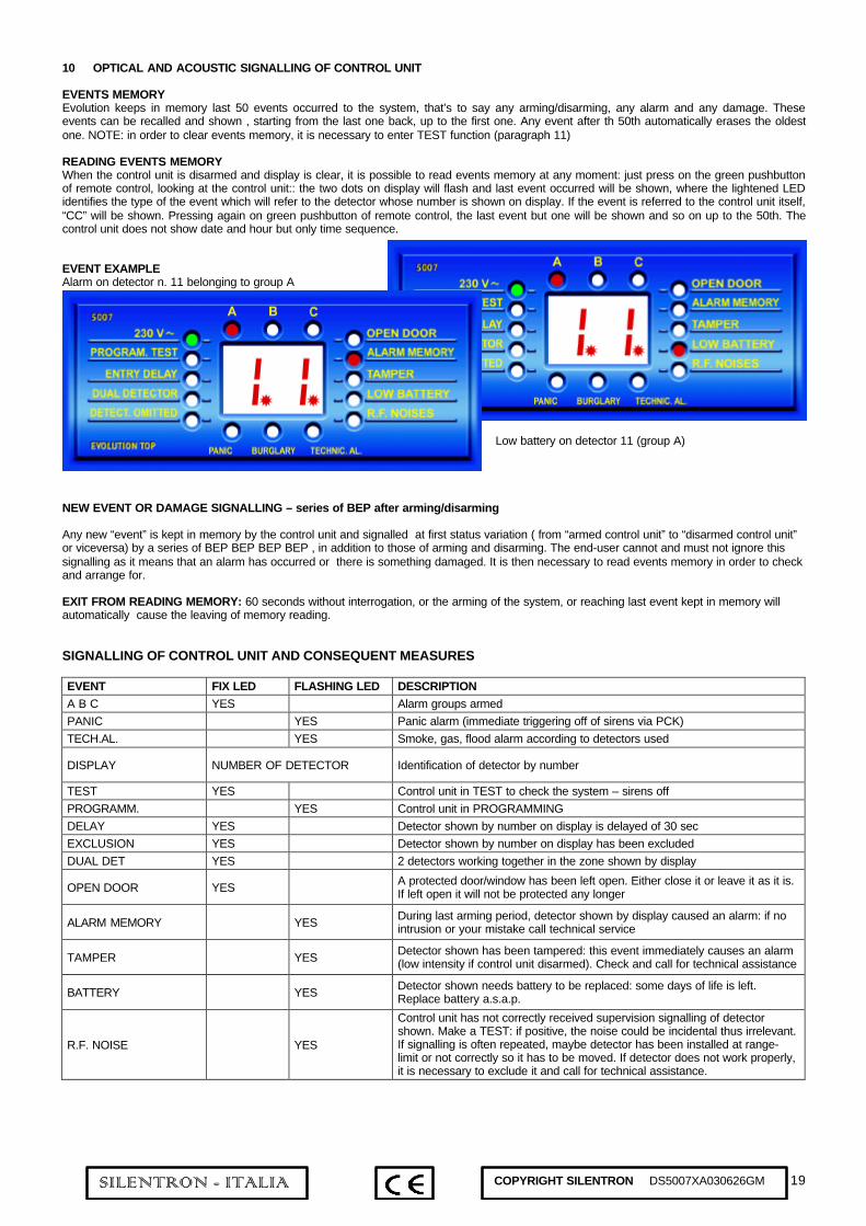
19SILENTRON - ITALIA COPYRIGHT SILENTRON DS5007XA030626GM
10 OPTICAL AND ACOUSTIC SIGNALLING OF CONTROL UNIT
EVENTS MEMORYEvolution keeps in memory last 50 events occurred to the system, that’s to say any arming/disarming, any alarm and any damage. Theseevents can be recalled and shown , starting from the last one back, up to the first one. Any event after th 50th automatically erases the oldestone. NOTE: in order to clear events memory, it is necessary to enter TEST function (paragraph 11)
READING EVENTS MEMORYWhen the control unit is disarmed and display is clear, it is possible to read events memory at any moment: just press on the green pushbuttonof remote control, looking at the control unit:: the two dots on display will flash and last event occurred will be shown, where the lightened LEDidentifies the type of the event which will refer to the detector whose number is shown on display. If the event is referred to the control unit itself,“CC” will be shown. Pressing again on green pushbutton of remote control, the last event but one will be shown and so on up to the 50th. Thecontrol unit does not show date and hour but only time sequence.
EVENT EXAMPLEAlarm on detector n. 11 belonging to group A
Low battery on detector 11 (group A)
NEW EVENT OR DAMAGE SIGNALLING – series of BEP after arming/disarming
Any new “event” is kept in memory by the control unit and signalled at first status variation ( from “armed control unit” to “disarmed control unit”or viceversa) by a series of BEP BEP BEP BEP , in addition to those of arming and disarming. The end-user cannot and must not ignore thissignalling as it means that an alarm has occurred or there is something damaged. It is then necessary to read events memory in order to checkand arrange for.
EXIT FROM READING MEMORY: 60 seconds without interrogation, or the arming of the system, or reaching last event kept in memory willautomatically cause the leaving of memory reading.
SIGNALLING OF CONTROL UNIT AND CONSEQUENT MEASURES
EVENT FIX LED FLASHING LED DESCRIPTIONA B C YES Alarm groups armedPANIC YES Panic alarm (immediate triggering off of sirens via PCK)TECH.AL. YES Smoke, gas, flood alarm according to detectors used
DISPLAY NUMBER OF DETECTOR Identification of detector by number
TEST YES Control unit in TEST to check the system – sirens offPROGRAMM. YES Control unit in PROGRAMMINGDELAY YES Detector shown by number on display is delayed of 30 secEXCLUSION YES Detector shown by number on display has been excludedDUAL DET YES 2 detectors working together in the zone shown by display
OPEN DOOR YES A protected door/window has been left open. Either close it or leave it as it is.If left open it will not be protected any longer
ALARM MEMORY YES During last arming period, detector shown by display caused an alarm: if nointrusion or your mistake call technical service
TAMPER YES Detector shown has been tampered: this event immediately causes an alarm(low intensity if control unit disarmed). Check and call for technical assistance
BATTERY YES Detector shown needs battery to be replaced: some days of life is left.Replace battery a.s.a.p.
R.F. NOISE YES
Control unit has not correctly received supervision signalling of detectorshown. Make a TEST: if positive, the noise could be incidental thus irrelevant.If signalling is often repeated, maybe detector has been installed at range-limit or not correctly so it has to be moved. If detector does not work properly,it is necessary to exclude it and call for technical assistance.
20SILENTRON - ITALIA COPYRIGHT SILENTRON DS5007XA030626GM
CONTROL UNIT SIGNALLING AND CONSEQUENT MEASURES
Display CC CC on display means that the event shown by LED concerns the control unit itself; in case “battery “ LED is on, immediatelyreplace control unit battery.
Display on on is shown when control unit is armed; it disappears after 60 seconds at the end of output time.Display - - this indication is shown when the control unit is disarmed; it disappears after 60 seconds.
11 TEST OF THE SYSTEM
In order to check the system without triggering off the sirens and the telephone diallers, it is necessary to use a PCK remote control as follows:
red and green pushbuttons: press them together for 1 second to have TEST function: TEST LED will light onred and green pushbuttons: in TEST condition, press them together for about 1 second to exclude chosen detectorred and green pushbuttons: in TEST condition, press them together for about 10 seconds to cancel all programmed remote controlsgreen pushbutton: see "reading events memory"white pushbutton: to choose position of detector (from 1 to 96); number moves forward at any pressingred pushbutton: end of the TEST and back to normal functioning
In TEST condition, sirens are blocked: some wireless models confirm the block with several BEEP (see concerned instructions): this is alsouseful to replace batteries without causing tamper alarm.
To check system’s functions, stir detectors one by one: a BEEP will be produced as well as the temporary lighting up of the number to whicheach detector giving alarm is referred.These alarms are kept in memory (up to 50) and can be checked looking into the events memory (paragraph 10) after leaving TEST condition. Atest per year is suggested.
TAKE CARE: in order to correctly check volumetric detectors 5011 PIR TOP and 5014 SILENT PIR, it is necessary to empty the protectedrooms of people and animals for at least three minutes before triggering off an alarm entering the protected area. In order to check the protectedarea, put each detector in TEST condition (refer to concerned instructions).
11.1 DETECTOR’S EXCLUSION
In case of damage of one detector, it is possible to temporarily exclude it out of the system. With control unit in TEST condition, look fordetector position pressing on white pushbutton of remote control for several times. Once located, press together the green and red pushbuttonsof remote control: the exclusion is confirmed and LED “DETECT. OMITTED” will show it. To bring back the omitted detector to normalfunctioning, repeat the operation.
12 SIGNALLING OF OTHER DEVICES
Some devices of the system give a further confirmation signalling, indipendent from control unit. Refer to concerned instructions.
5026 PA TOP
Red LED on = system armedYellow LED flashing = alarm occurredGreen LED on = mains presence
5030 SRA TOP 5034 SR-P
BEP BEP BEP at arming of control unitBEP at disarming of control unitLong BEEEEP for 30 seconds = low battery – to be replaced within 48 hours
VARIOUS RADIO DETECTORS
All detectors also give a local indication (BEEP at any alarm) need for battery replacement (within some days)

21SILENTRON - ITALIA COPYRIGHT SILENTRON DS5007XA030626GM
PART TWO – INSTALLATIONS AND PROGRAMMING
13 TECHNICAL CHARACTERISTICS OF CONTROL PANEL 5007 EVOLUTION TOP (also refer to 13.1 and electrical scheme)
Intrusion alarm by radio: up to 96 detectors, can be programmed either immediate or delayed on 3 arming groups (A-B-C) or on 24 hourszones Panic, Burglar, Technical alarm
by Wire: 3 NC zones identified by numbers 99A (group A) – 99B (group B) – 99C (group C)
Tamper alarm by radio: tamper signalling received by each detector - "existing in life” signalling and low-battery signalling (SUPERVISION)by wire: tamper NC line for protection against opening and tampering of control unit
R.F. Noise Alarm test of radio frequencies with noise signalling and trouble on frequency
Delay: arming delayed of 60 seconds – alarm time 3 minutes – entry delayed of 30 seconds only on detectors soprogrammed
Indications: 16 function LED and number identification of detector on 2 digit display
Inner siren: 106 dB in alarm – adjustable intensity for signalling function
Digital dialler(ref 5007 C only): transmission to 8 telephone numbers of Ademco-Scantronic and/or Contact ID protocols + acousticsignalling to be identified by end user programming. See specific instructions.
Controls: Remote controls 5023P PCK 4P (4 pushbuttons) and 5024P PCK 3P (3 pushbuttons). The control unit is suppliedequipped with 1 PCK 3P
RADIO RECEIVING-TRANSMITTING: digital random code, factory-encoded, programmed by microprocessor self-learning – frequency andpower according to Law – radio range. 100meters in open air and in total absence of noise on the band. It can sensibly reduce inside,according to positioning, to building structure and/or to possible trouble on the band. Always check that radio range is good enough beforestarting final installation.
SIZE: 310x214x91 WEIGHT: 2,6 Kg. BOX: white/grey ABS TEMPERATURE: working and stocking temperature – 20° + 50°
13.1 TECHNICAL CHARACTERISTICS OF WIRE CONNECTIONS
Supplying 230V AC: connect to the mains only once the installation is finished, programming and test with battery only
Consumption: P.C.B. = 20 mA in stand-byTo calculate autonomy, take into consideration battery capacity, P.C.B. consumption and all external chargeswire connected
DC Battery charger: max 600 mA at 13,8 V with electronic protection (see scheme)Standard back-up battery 12 V 7 Ah (necessary but not provided)
Adjustment points: RESET programming total-reset pushbuttonScanner on/off of radio-noise service and supervisionBZ adjustment of signalling BEEPJP 4 jumper in this position for normal working of receiverJP 5 jumper in this position for decreasing 3db receiverMHz to make radio range testsIN – OUT connections on switches for telephone line and telephone – plug for telephone line – plug for
PC programming – for Evolution/c models
CONNECTIONS: see to scheme (end of the book)
14 CARE FOR A CORRECT INSTALLATION (see picture 1)
Any installation must take into account different environmental conditions, it requires skillness and care. Mistakes during installation can causebad functioning of the system, not due to the devices.
Before starting installation, it is necessary to choose type and position of wireless and hard-wired detectors as well as their partition on the threegroups for part-setting. It is necessary to fill out the chart on the last page. Detectors and remote controls with special functions (24 hours) willhave to be programmed on special zones. Remote controls range can vary according to position or to the way they are handled duringtransmission: check most favourable conditions. All physical obstacles cause a loss of radio range. In order to check power of the signalreceived, move jumper from position JP4 to position JP5 and check correct receiving of the signals. We suggest to use Field Meter device,placing it near the control unit and checking signals received reach at least the yellow part (picture 2). During transmission absence the noiseshown by Field Meter must not get over the green part.
Hard-wired installation: take into account passing of cables for sirens, diallers etc. Any device must be connected to switches according toscheme. Calculate consumption of hard-wired devices and check that total amount can be supplied by supply unit ( max 1 A – 700 mAcontinuous)
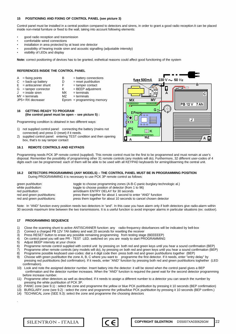
22SILENTRON - ITALIA COPYRIGHT SILENTRON DS5007XA030626GM
15 POSITIONING AND FIXING OF CONTROL PANEL (see picture 3)
Control panel must be installed in a central position compared to detectors and sirens, in order to grant a good radio reception.It can be placedinside non-metal furniture or fixed to the wall, taking into account following elements:
• good radio reception and transmission• comfortable wired connections• installation in area protected by at least one detector• possibility of hearing inside siren and acoustic signalling (adjustable intensity)• visibility of LEDs and display
Note: correct positioning of devices has to be granted, esthetical reasons could affect good functioning of the system
REFERENCES INSIDE THE CONTROL PANEL
A = fixing points B = battery connectionsC = back-up battery D = reset pushbuttonE = antiscanner shunt F = tamper contactG = tamper connector K = BEEP adjustmentJ = inside siren MX = terminalsMY = terminals MZ = terminalsJP5= RX decreaser Eprom = programming memory
16 GETTING READY TO PROGRAM(the control panel must be open – see picture 5) :
Programming condition is obtained in two different ways:
1) not supplied control panel: connecting the battery (mains not connected) and press D (reset) if it needs.
2) supplied control panel: entering TEST condition and then opening box, that’s to say tamper contact
16.1 REMOTE CONTROLS AND KEYPADS
Programming needs PCK 3P remote control (supplied). This remote control must be the first to be programmed and must remain at user’sdisposal. Remember the possibility of programming other 31 remote controls (any models will do). Furthermore, 32 different user-codes of 4digits each can be programmed: each of them will be able to be used with all KEYPAD keyboards for arming/disarming the central unit.
16.2 DETECTORS PROGRAMMING (ANY MODELS) – THE CONTROL PANEL MUST BE IN PROGRAMMING POSITIONDuring PROGRAMMING it is necessary to use PCK 3P remote control as follows:
green pushbutton: toggle to choose programming zones (A-B-C-panic-burglary-technologic al.)white pushbutton: toggle to choose position of detector (from 1 to 96)red pushbutton: arm/disarm ENTRY DELAY for 30 secondsred and green pushbuttons: press them together for about 1 second to enter “AND” functionred and green pushbuttons: press them together for about 10 seconds to cancel chosen detector
Note: In “AND” function every position needs two detectors in “and”. In this case you have alarm only if both detectors give radio-alarm within30 seconds maximum time between the two transmissions. It is a useful function to avoid improper alarms in particular situations (ex: outdoor).
17 PROGRAMMING SEQUENCE
1) Close the scanning shunt to active ANTISCANNER function: any radio-frequency disturbances will be indicated by bell-box2) Connect a charged PB 12V 7Ah battery and wait 20 seconds for resetting the receiver3) Press RESET button to erase any possible remaining programming from testing stage (BEEEEEP)4) On control panel you will see PR - TEST LED. switched on: you are ready to start PROGRAMMING5) Adjust BEEP intensity at your choice6) Programme remote control supplied with control unit by pressing on both red and green keys until you hear a sound confirmation (BEP)7) Programme other remote controls (any models will do), by pressing on both red and green keys until you hear a sound confirmation (BEP)8) Programme possible keyboard user-codes: dial a 4 digit code then press both red and green pushbuttons together (BEP)9) Choose with green pushbutton the zone A, B, C where you want to programme the first detector. If it needs, enter "entry delay" by
pressing red pushbuttons (led confirmation). If it needs, enter "AND" function by pressing both red and green pushbuttons toghether (LEDconfirmation).
10) Look and note the assigned detector number. Insert battery into the detector: it will be stored when the control panel gives a BEPconfirmation and the detector number increases. When the "AND" function is required the panel wait for the second detector programming
before increase number.11) Programme other detectors as well as described. If it needs to assign a different number to a detector you can search the number by
pressing the white pushbutton of PCK 3P.12) PANIC zone (see 9.1) : select the zone and programme the yellow or blue PCK pushbutton by pressing it 10 seconds (BEP confirmation)13) BURGLARY zone (see 9.2) : select the zone and programme the yellow/blue PCK pushbutton by pressing it 10 seconds (BEP confirm.)14) TECHNICAL zone (SEE 9.3): select the zone and programme the choosing detectors
.
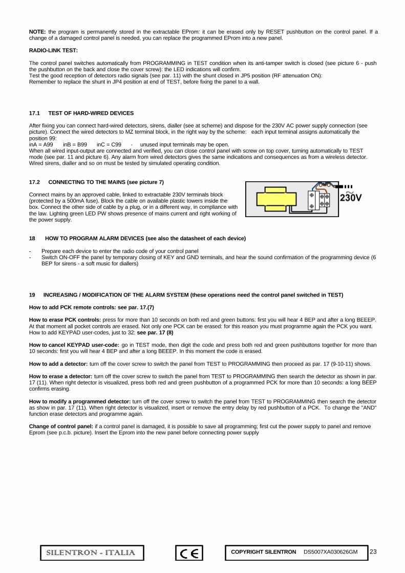
23SILENTRON - ITALIA COPYRIGHT SILENTRON DS5007XA030626GM
NOTE: the program is permanently stored in the extractable EProm: it can be erased only by RESET pushbutton on the control panel. If achange of a damaged control panel is needed, you can replace the programmed EProm into a new panel.
RADIO-LINK TEST:
The control panel switches automatically from PROGRAMMING in TEST condition when its anti-tamper switch is closed (see picture 6 - pushthe pushbutton on the back and close the cover screw): the LED indications will confirm.Test the good reception of detectors radio signals (see par. 11) with the shunt closed in JP5 position (RF attenuation ON):Remember to replace the shunt in JP4 position at end of TEST, before fixing the panel to a wall.
17.1 TEST OF HARD-WIRED DEVICES
After fixing you can connect hard-wired detectors, sirens, dialler (see at scheme) and dispose for the 230V AC power supply connection (seepicture). Connect the wired detectors to MZ terminal block, in the right way by the scheme: each input terminal assigns automatically theposition 99:inA = A99 inB = B99 inC = C99 - unused input terminals may be open.When all wired input-output are connected and verified, you can close control panel with screw on top cover, turning automatically to TESTmode (see par. 11 and picture 6). Any alarm from wired detectors gives the same indications and consequences as from a wireless detector.Wired sirens, dialler and so on must be tested by simulated operating condition.
17.2 CONNECTING TO THE MAINS (see picture 7)
Connect mains by an approved cable, linked to extractable 230V terminals block(protected by a 500mA fuse). Block the cable on available plastic towers inside thebox. Connect the other side of cable by a plug, or in a different way, in compliance withthe law. Lighting green LED PW shows presence of mains current and right working ofthe power supply.
18 HOW TO PROGRAM ALARM DEVICES (see also the datasheet of each device)
- Prepare each device to enter the radio code of your control panel- Switch ON-OFF the panel by temporary closing of KEY and GND terminals, and hear the sound confirmation of the programming device (6
BEP for sirens - a soft music for diallers)
19 INCREASING / MODIFICATION OF THE ALARM SYSTEM (these operations need the control panel switched in TEST)
How to add PCK remote controls: see par. 17.(7)
How to erase PCK controls: press for more than 10 seconds on both red and green buttons: first you will hear 4 BEP and after a long BEEEP.At that moment all pocket controls are erased. Not only one PCK can be erased: for this reason you must programme again the PCK you want.How to add KEYPAD user-codes, just to 32: see par. 17 (8)
How to cancel KEYPAD user-code: go in TEST mode, then digit the code and press both red and green pushbuttons together for more than10 seconds: first you will hear 4 BEP and after a long BEEEP. In this moment the code is erased.
How to add a detector: turn off the cover screw to switch the panel from TEST to PROGRAMMING then proceed as par. 17 (9-10-11) shows.
How to erase a detector: turn off the cover screw to switch the panel from TEST to PROGRAMMING then search the detector as shown in par.17 (11). When right detector is visualized, press both red and green pushbutton of a programmed PCK for more than 10 seconds: a long BEEPconfirms erasing.
How to modify a programmed detector: turn off the cover screw to switch the panel from TEST to PROGRAMMING then search the detectoras show in par. 17 (11). When right detector is visualized, insert or remove the entry delay by red pushbutton of a PCK. To change the "AND"function erase detectors and programme again.
Change of control panel: if a control panel is damaged, it is possible to save all programming; first cut the power supply to panel and removeEprom (see p.c.b. picture). Insert the Eprom into the new panel before connecting power supply

24SILENTRON - ITALIA COPYRIGHT SILENTRON DS5007XA030626GM
Erster Teil - FUNKTION UND VERWENDUNG DER ZENTRALE
1 FUNKTIONSPRINZIP
Das Alarmsystem EVOLUTION TOP besteht aus einer Anzahl von mit Batterien und/oder Drahtverbindungen funktionierenden Geräten. Beifachgerechter Installation in Gebäuden wird das unberechtigte Betreten gemeldet und ein Vor-Ort-Alarm, sowie eine Fernmeldung ausgelöst.Mit entsprechendem Zubehör ausgerüstet, können die Systeme EVOLUTION andere gefährliche Vorkommnisse erfassen oder melden, wieÜbelkeit – Überfall oder Raub – Gasaustritt – Brände – Überschwemmungen.
Die Zentrale steuert die Kontrolle der Melder und der Alarmmittel (drahtlos und verdrahtet). Sie ist immer betriebsbereit, um denAntisabotageschutz des Systems und die Alarmkontrolle “rund um die Uhr” zu gewährleisten.Die Zentrale sieht die Möglichkeit vor, drei Alarmzonen einzeln scharfzuschalten. Die verschiedenen Melder daher schon im Voraus je nachBedarf des Benutzers auf die drei Zonnen verteilen.
Bei der Installation des Systems sind die Eigenschaften der einzelnen Funk- oder verdrahteten Komponenten zu berücksichtigen, inAbhängigkeit von den Einbruchsrisiken und Anforderungen des Benutzers. Alle handelsüblichen Melder und verdrahteten Alarmmittel sindkompatibel mit der Zentrale EVOLUTION TOP: Diese sollten in der nachstehenden Anlagentabelle eingetragen werden.
INSTALLATIONSBEISPIEL MIT AUFTEILUNG IN ZONEN (Abb. 1):
Zone A = Überwachung ErdgeschoßZone B = Überwachung erster StockZone C = Überwachung Garage
2 BESTANDTEILE DES FUNKALARMSYSTEMS EVOLUTION
5030 SRA TOP Funkaußensirene, Versorgung durch Lithiumbatterie, komplett mit Blitzleuchte5034 SR - P Funkinnensirene, Versorgung durch Stabbatterien.5011 PIR TOP Passiv-Infrarotmelder zur Erfassung von Bewegungen in Bereichen von über 60 qm5015-16-17 SENSOR TOP Sensor zum Schutz von Türen und Fenstern gegen gewaltsames Öffnen, mit Klemmen für weitere
Außensensoren5020-21-22 SENSOR SLIM Sensor zum Schutz von Türen und Fenstern gegen gewaltsames Öffnen, Lithiumbatterie 5 Jahre
Lebensdauer5013 LASERBEAM Drahtlose Infrarotstrahlenschranke zum Schutz von Türen und Fenstern auch in Außenbereichen
(siehe Bedienungsanleitungen)5014 SILENT PIR Infrarotbewegungsmelder für Außenbereiche – fächerförmiger Schutz5024 P PCK 3P Handsender zum Gesamtscharf-, Teilscharf-, Unscharfschalten der Zonen A+B5023 P PCK 4P Handsender zum Gesamtscharf-, Teilscharf-, Unscharfschalten (A+B) und Panikalarm5023 PCK 4 Handsender zum Scharf-/Unscharfschalten, Panikalarm, zusätzliche Hilfssteuerung5028 KEYPAD Code-Tastatur zum Gesamtscharf-, Teilscharf-, Unscharfschalten mit Paniktaste5026 PA WLR Außenmelder für Anlagenzustand, Netzbetrieb und Alarm5007 EVOLUTION TOP Alarmzentrale - 96 Funk- und weitere drahtgebundene Melder, auf 3 Zonen aufgeteilt, technische und
Panikalarme mit Netzgerät, Sirene und (nur Modell 5007 C) integriertem digitalem Wählgerät.
3 ZENTRALE EVOLUTION TOP - FUNKTIONEN
• Äußerste Einfachkeit der Programmierung und Kontrolle der Vorkommnisse.• 96 Meldelinien - 96 programmierbare Melder, Identifizierung des einzelnen Melders auf dem Display.• Programmierung in “UND” von 2 Meldern pro Linie. Möglichkeit der Alarmverzögerung für jeden Melder.• Gesamt-, Teil-, Unscharfschaltung durch Handsender PCK und PCK-P. Programmierung von bis zu 32 PCK.• Gesamt-, Teil-, Unscharfschaltung durch eine oder mehrere Tastaturen Keypad mit numerischem Code – bis zu 32 verschiedene Codes• Scharf/Unscharfschaltung mit elektronischem oder elektromechanischem Schlüssel per Draht• 3 NC-Eingänge für verdrahtete Alarmmelder• LED- und Display-Anzeige aller Funktionen der einzelnen Melder• Die letzten 50 Vorkommnisse werden in chronologischer Reihenfolge angezeigt und gespeichert• Elektrische Ausgänge für Alarmgeräte und Fernüberwachung• Unterschiedliche akustische Alarme für Einbruch - Panik - Überfall• Technische Alarme (Rauch-Gas-Überschwemmung) durch Verbindung von SENSOR TOP mit spezifischen Meldern• Sabotagealarm für alle Bestandteile des Systems (ausschließlich Handsender)• Überwachungsalarm bei leerer Batterie und/oder Defekt eines Melders• Scanneralarm bei Funkstörungen oder Sperrversuchen der Funkübertragungen des Systems• Testmöglichkeit für jeden einzelnen Bestandteil des Systems• Modell /C mit integriertem Wählgerät für 8 Nummern (Protokol Ademco/ Scantronic und Contact ID)• Modell /C mit Möglichkeit von telefonischen Alarmanrufen an Privatnummern

25SILENTRON - ITALIA COPYRIGHT SILENTRON DS5007XA030626GM
3.1 ZUSÄTZLICHE FUNKTIONEN DES SYSTEMS EVOLUTION (ohne Verkabelung)
STEUERUNG VON ELEKTRISCHEN STROMVERBRAUCHERN DURCH HANDSENDER UND/ODER TASTATURENDie Handsender PCK und die Tastaturen KEYPAD können schon vorhandene Hausautomationen steuern, wie z.B. elektrische Tore und/odermotorisierte Rolläden, sowie, mit den drahtlosen Emfangsgeräten RX 1 und RX 2, Lichtquellen und andere Stromverbraucher bis zu 8A und230V ein- und ausschalten. Jeder mit einem Empfangsgerät Silentron verbundene Stromverbraucher kann auch von Außen telefonisch überdas Gerät Multiactiva, Art.Nr. 5160, gesteuert werden. Weitere Auskünfte können vom Installateur erteilt oder unserer Internetseitewww.silentron.it entnommen werden.AUTOMATISCHE LICHTEINSCHALTUNGIn allen Räumen, in denen ein Melder Silentron angebracht ist, besteht die Möglichkeit, die dort befindlichen Lichtquellen – durch ein oderemehrere, an die vorhandenen Schalter angeschlossene Empfangsgeräte Silentron RX2 – automatisch einzuschalten. Das automatischeEinschalten erfolgt erst bei Dunkelheit und mit einer einstellbaren Zeitdauer jedesmal, wenn der Melder eine Bewegung erfaßt, unabhängigdavon, ob die Anlage scharfgeschaltet ist oder nicht.Außer dem Vorteil der automatischen Lichteinschaltung wird hiemit auch ein höherer Abschreckeffekt des Alarmsystems bei unerwüschtemEindringen erzielt.
SCHUTZ GEGEN ÜBERFALLDurch entsprechende Melder (5013 - 5014) ist es möglich, einen Schutz in Außenbereichen zu erzielen. In diesem Fall müssen die Melderimmer in "UND"-Funktion programmiert werden (siehe Punkt 16.2). ACHTUNG: Bei dieser Schutzart sind falsche Alarme unvermeidbar, wasnur durch eine äußerst sorfältige Installtion auf ein Mindestmaß beschränkt werden kann.
4 LED-ANZEIGEN DER ZENTRALE EVOLUTION TOP (Abb. 2)
Jede Funktion des Systems wird von der Zentrale deutlich durch LEDs und Display angezeigt. Die Bedeutung der Anzeigen ist unter Punkt 10beschrieben..
5 GESAMTSCHARFSCHALTUNG DES SYSTEMS
Die Zentrale wird durch Drücken der roten Taste eines Handsenders scharfgeschaltet. Alle LEDs der scharfgeschalteten Zonen leuchten aufund es erfolgt eine akustische Meldung (3 Pieptöne). Das System ist nach 60” betriebsbereit. Die Meldung kann von eventuellen Sirenenwiederholt werden.Die Scharfschaltung kann auch über eine Tastatur vorgenommen werden, durch Eingeben der 4 Ziffern des Codes und anschließendesDrücken der roten Taste: Es erfolgt dieselbe Bestätigung.Nach einer Scharfschaltung können Funktions- oder Störmeldungen vorliegen. Siehe unter Punkt 10 “Meldungen”.
6 TEILSCHARFSCHALTUNG DES SYSTEMS (Abb. 3)
a) Mit einem Handsender 5023P oder 5024P können unmittelbar nur die Zonen A + B durch Drücken der weißen Taste scharfgeschaltetwerden. Das System ist nach 60” betriebsbereit.
b) Die Teilscharfschaltung kann auch über eine oder mehrere Tastaturen vorgenommen werden, durch Eingeben der 4 Ziffern des Codes unddanach Drücken der Tasten A-B-C, d.h der Zonen, die ausgeschlossen werden sollen. Auf der Tastatur gehen die entsprechenden LEDs aus.Durch anschließendes Drücken der roten Taste wird die Scharfschaltung der gewünschten Zonen bestätigt.Das System ist nach 60” betriebsbereit.
Die Zentrale bestätigt die Scharfschaltung durch ein akustisches Signal (anhaltender Piepton) und zeigt die scharfgeschalteten Zonen beimVerlassen des Raumes durch Aufleuchten der entsprechenden LEDs A-B-C an.
Nach einer Teilscharfschaltung können Störmeldungen vorliegen. Siehe unter Punkt 10 “Meldungen”.
7 UNSCHARFSCHALTUNG DES SYSTEMS
Die Zentrale wird durch Drücken der grünen Taste eines Handsenders unscharf geschaltet. Es erfolgt eine akustische Meldung der Zentrale(Piepton), die von eventuellen Sirenen wiederholt wird. Die Unscharfschaltung kann auch über eine Tastatur vorgenommen werden, durchEingeben der 4 Ziffern des Codes und anschließendes Drücken der grünen Taste Es erfolgt dieselbe Bestätigung.Nach einer Unscharfschaltung können Funktions- oder Störmeldungen vorliegen. Siehe unter Punkt 10 “Meldungen”.
8 EINBRUCHSALARM
Jeder angesprochene Melder überträgt ein Alarmsignal an die Zentrale: Falls diese scharfgeschaltet ist, erfolgt ein Alarmzyklus von dreiMinuten.Bei erneutem Einbruchsversuch werden durch die Zentrale bis zu 3 Alarmzyklen ausgelöst, mit Wiederholung für jeden Melder und bis zu einemMaximum von 8 Alarmzyklen insgesamt für jede Scharfschaltungsdauer, mit darauffolgender Sperre zur Wahrung der öffentlichen Ruhe.Die mit der Funktion “Eingangsverzögerung” programmierten Melder übertragen einen Alarm mit einer Verzögerung von 30”, um den Zutritt zuden geschützten Räumen und eventuelle Maßnahmen auf der Tastatur zu gestatten. Während dieser Zeit gibt die Zentrale wiederholteWarnpieptöne aus.Jeder ausgelöste Alarm wird von den Kontrolleuchten des entsprechenden Kanals gespeichert und durch aufeinanderfolgendePieptöne beim Unscharfschalten des Systems angezeigt.Eine Steuerung zur “Unscharfschaltung” unterbricht eventuell eingehende Alarme.
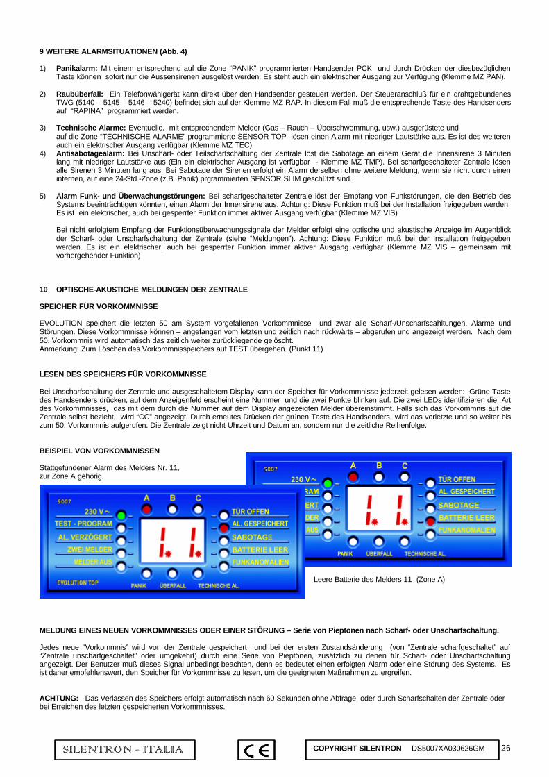
26SILENTRON - ITALIA COPYRIGHT SILENTRON DS5007XA030626GM
9 WEITERE ALARMSITUATIONEN (Abb. 4)
1) Panikalarm: Mit einem entsprechend auf die Zone “PANIK” programmierten Handsender PCK und durch Drücken der diesbezüglichenTaste können sofort nur die Aussensirenen ausgelöst werden. Es steht auch ein elektrischer Ausgang zur Verfügung (Klemme MZ PAN).
2) Raubüberfall: Ein Telefonwählgerät kann direkt über den Handsender gesteuert werden. Der Steueranschluß für ein drahtgebundenesTWG (5140 – 5145 – 5146 – 5240) befindet sich auf der Klemme MZ RAP. In diesem Fall muß die entsprechende Taste des Handsendersauf “RAPINA” programmiert werden.
3) Technische Alarme: Eventuelle, mit entsprechendem Melder (Gas – Rauch – Überschwemmung, usw.) ausgerüstete undauf die Zone “TECHNISCHE ALARME” programmierte SENSOR TOP lösen einen Alarm mit niedriger Lautstärke aus. Es ist des weiterenauch ein elektrischer Ausgang verfügbar (Klemme MZ TEC).
4) Antisabotagealarm: Bei Unscharf- oder Teilscharfschaltung der Zentrale löst die Sabotage an einem Gerät die Innensirene 3 Minutenlang mit niedriger Lautstärke aus (Ein ein elektrischer Ausgang ist verfügbar - Klemme MZ TMP). Bei scharfgeschalteter Zentrale lösenalle Sirenen 3 Minuten lang aus. Bei Sabotage der Sirenen erfolgt ein Alarm derselben ohne weitere Meldung, wenn sie nicht durch eineninternen, auf eine 24-Std.-Zone (z.B. Panik) prgrammierten SENSOR SLIM geschützt sind.
5) Alarm Funk- und Überwachungstörungen: Bei scharfgeschalteter Zentrale löst der Empfang von Funkstörungen, die den Betrieb desSystems beeinträchtigen könnten, einen Alarm der Innensirene aus. Achtung: Diese Funktion muß bei der Installation freigegeben werden.Es ist ein elektrischer, auch bei gesperrter Funktion immer aktiver Ausgang verfügbar (Klemme MZ VIS)
Bei nicht erfolgtem Empfang der Funktionsüberwachungssignale der Melder erfolgt eine optische und akustische Anzeige im Augenblickder Scharf- oder Unscharfschaltung der Zentrale (siehe “Meldungen”). Achtung: Diese Funktion muß bei der Installation freigegebenwerden. Es ist ein elektrischer, auch bei gesperrter Funktion immer aktiver Ausgang verfügbar (Klemme MZ VIS – gemeinsam mitvorhergehender Funktion)
10 OPTISCHE-AKUSTICHE MELDUNGEN DER ZENTRALE
SPEICHER FÜR VORKOMMNISSE
EVOLUTION speichert die letzten 50 am System vorgefallenen Vorkommnisse und zwar alle Scharf-/Unscharfscahltungen, Alarme undStörungen. Diese Vorkommnisse können – angefangen vom letzten und zeitlich nach rückwärts – abgerufen und angezeigt werden. Nach dem50. Vorkommnis wird automatisch das zeitlich weiter zurückliegende gelöscht.Anmerkung: Zum Löschen des Vorkommnisspeichers auf TEST übergehen. (Punkt 11)
LESEN DES SPEICHERS FÜR VORKOMMNISSE
Bei Unscharfschaltung der Zentrale und ausgeschaltetem Display kann der Speicher für Vorkommnisse jederzeit gelesen werden: Grüne Tastedes Handsenders drücken, auf dem Anzeigenfeld erscheint eine Nummer und die zwei Punkte blinken auf. Die zwei LEDs identifizieren die Artdes Vorkommnisses, das mit dem durch die Nummer auf dem Display angezeigten Melder übereinstimmt. Falls sich das Vorkommnis auf dieZentrale selbst bezieht, wird “CC” angezeigt. Durch erneutes Drücken der grünen Taste des Handsenders wird das vorletzte und so weiter biszum 50. Vorkommnis aufgerufen. Die Zentrale zeigt nicht Uhrzeit und Datum an, sondern nur die zeitliche Reihenfolge.
BEISPIEL VON VORKOMMNISSEN
Stattgefundener Alarm des Melders Nr. 11,zur Zone A gehörig.
Leere Batterie des Melders 11 (Zone A)
MELDUNG EINES NEUEN VORKOMMNISSES ODER EINER STÖRUNG – Serie von Pieptönen nach Scharf- oder Unscharfschaltung.
Jedes neue “Vorkommnis” wird von der Zentrale gespeichert und bei der ersten Zustandsänderung (von “Zentrale scharfgeschaltet” auf“Zentrale unscharfgeschaltet” oder umgekehrt) durch eine Serie von Pieptönen, zusätzlich zu denen für Scharf- oder Unscharfschaltungangezeigt. Der Benutzer muß dieses Signal unbedingt beachten, denn es bedeutet einen erfolgten Alarm oder eine Störung des Systems. Esist daher empfehlenswert, den Speicher für Vorkommnisse zu lesen, um die geeigneten Maßnahmen zu ergreifen.
ACHTUNG: Das Verlassen des Speichers erfolgt automatisch nach 60 Sekunden ohne Abfrage, oder durch Scharfschalten der Zentrale oderbei Erreichen des letzten gespeicherten Vorkommnisses.
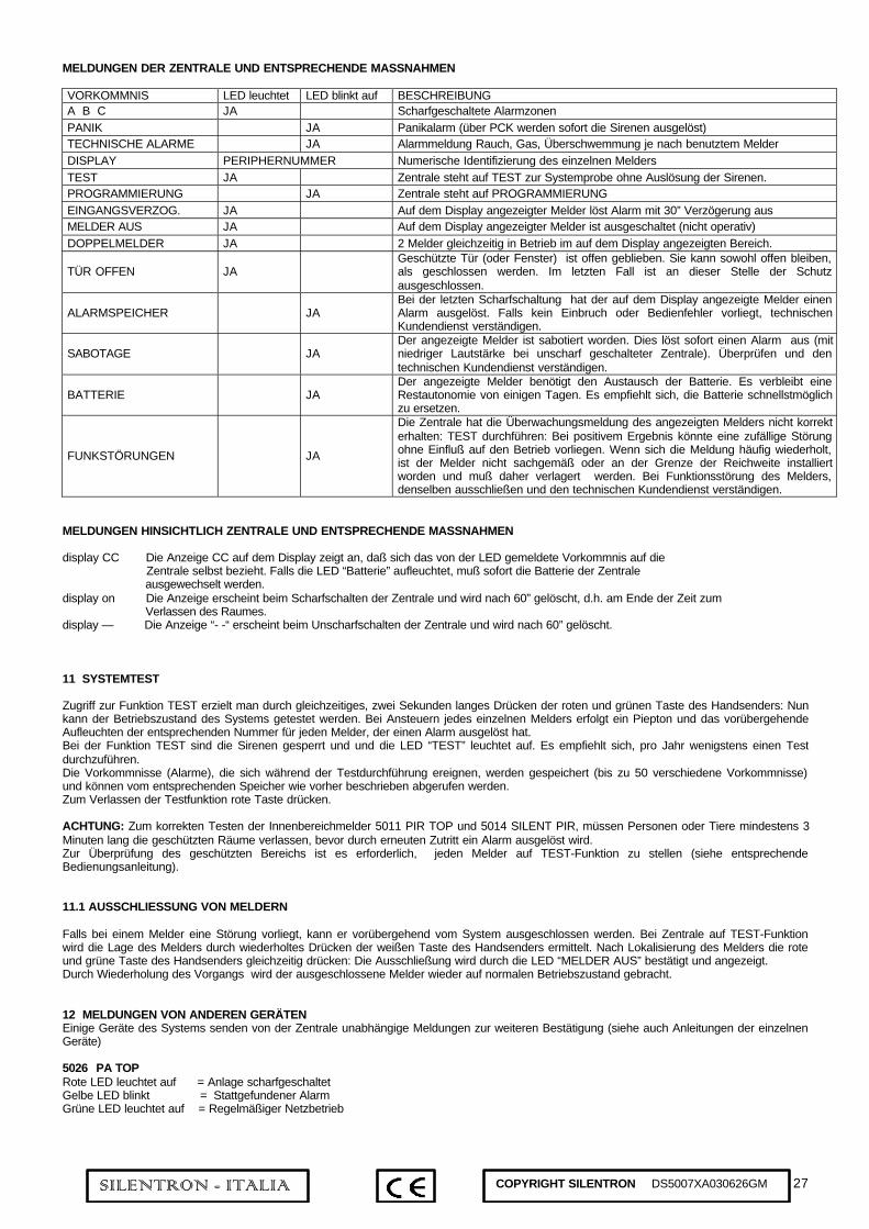
27SILENTRON - ITALIA COPYRIGHT SILENTRON DS5007XA030626GM
MELDUNGEN DER ZENTRALE UND ENTSPRECHENDE MASSNAHMEN
VORKOMMNIS LED leuchtet LED blinkt auf BESCHREIBUNGA B C JA Scharfgeschaltete AlarmzonenPANIK JA Panikalarm (über PCK werden sofort die Sirenen ausgelöst)TECHNISCHE ALARME JA Alarmmeldung Rauch, Gas, Überschwemmung je nach benutztem MelderDISPLAY PERIPHERNUMMER Numerische Identifizierung des einzelnen MeldersTEST JA Zentrale steht auf TEST zur Systemprobe ohne Auslösung der Sirenen.PROGRAMMIERUNG JA Zentrale steht auf PROGRAMMIERUNGEINGANGSVERZOG. JA Auf dem Display angezeigter Melder löst Alarm mit 30” Verzögerung ausMELDER AUS JA Auf dem Display angezeigter Melder ist ausgeschaltet (nicht operativ)DOPPELMELDER JA 2 Melder gleichzeitig in Betrieb im auf dem Display angezeigten Bereich.
TÜR OFFEN JAGeschützte Tür (oder Fenster) ist offen geblieben. Sie kann sowohl offen bleiben,als geschlossen werden. Im letzten Fall ist an dieser Stelle der Schutzausgeschlossen.
ALARMSPEICHER JABei der letzten Scharfschaltung hat der auf dem Display angezeigte Melder einenAlarm ausgelöst. Falls kein Einbruch oder Bedienfehler vorliegt, technischenKundendienst verständigen.
SABOTAGE JADer angezeigte Melder ist sabotiert worden. Dies löst sofort einen Alarm aus (mitniedriger Lautstärke bei unscharf geschalteter Zentrale). Überprüfen und dentechnischen Kundendienst verständigen.
BATTERIE JADer angezeigte Melder benötigt den Austausch der Batterie. Es verbleibt eineRestautonomie von einigen Tagen. Es empfiehlt sich, die Batterie schnellstmöglichzu ersetzen.
FUNKSTÖRUNGEN JA
Die Zentrale hat die Überwachungsmeldung des angezeigten Melders nicht korrekterhalten: TEST durchführen: Bei positivem Ergebnis könnte eine zufällige Störungohne Einfluß auf den Betrieb vorliegen. Wenn sich die Meldung häufig wiederholt,ist der Melder nicht sachgemäß oder an der Grenze der Reichweite installiertworden und muß daher verlagert werden. Bei Funktionsstörung des Melders,denselben ausschließen und den technischen Kundendienst verständigen.
MELDUNGEN HINSICHTLICH ZENTRALE UND ENTSPRECHENDE MASSNAHMEN
display CC Die Anzeige CC auf dem Display zeigt an, daß sich das von der LED gemeldete Vorkommnis auf die Zentrale selbst bezieht. Falls die LED “Batterie” aufleuchtet, muß sofort die Batterie der Zentrale ausgewechselt werden.display on Die Anzeige erscheint beim Scharfschalten der Zentrale und wird nach 60” gelöscht, d.h. am Ende der Zeit zum Verlassen des Raumes.display — Die Anzeige “- -“ erscheint beim Unscharfschalten der Zentrale und wird nach 60” gelöscht.
11 SYSTEMTEST
Zugriff zur Funktion TEST erzielt man durch gleichzeitiges, zwei Sekunden langes Drücken der roten und grünen Taste des Handsenders: Nunkann der Betriebszustand des Systems getestet werden. Bei Ansteuern jedes einzelnen Melders erfolgt ein Piepton und das vorübergehendeAufleuchten der entsprechenden Nummer für jeden Melder, der einen Alarm ausgelöst hat.Bei der Funktion TEST sind die Sirenen gesperrt und und die LED “TEST” leuchtet auf. Es empfiehlt sich, pro Jahr wenigstens einen Testdurchzuführen.Die Vorkommnisse (Alarme), die sich während der Testdurchführung ereignen, werden gespeichert (bis zu 50 verschiedene Vorkommnisse)und können vom entsprechenden Speicher wie vorher beschrieben abgerufen werden.Zum Verlassen der Testfunktion rote Taste drücken.
ACHTUNG: Zum korrekten Testen der Innenbereichmelder 5011 PIR TOP und 5014 SILENT PIR, müssen Personen oder Tiere mindestens 3Minuten lang die geschützten Räume verlassen, bevor durch erneuten Zutritt ein Alarm ausgelöst wird.Zur Überprüfung des geschützten Bereichs ist es erforderlich, jeden Melder auf TEST-Funktion zu stellen (siehe entsprechendeBedienungsanleitung).
11.1 AUSSCHLIESSUNG VON MELDERN
Falls bei einem Melder eine Störung vorliegt, kann er vorübergehend vom System ausgeschlossen werden. Bei Zentrale auf TEST-Funktionwird die Lage des Melders durch wiederholtes Drücken der weißen Taste des Handsenders ermittelt. Nach Lokalisierung des Melders die roteund grüne Taste des Handsenders gleichzeitig drücken: Die Ausschließung wird durch die LED “MELDER AUS” bestätigt und angezeigt.Durch Wiederholung des Vorgangs wird der ausgeschlossene Melder wieder auf normalen Betriebszustand gebracht.
12 MELDUNGEN VON ANDEREN GERÄTENEinige Geräte des Systems senden von der Zentrale unabhängige Meldungen zur weiteren Bestätigung (siehe auch Anleitungen der einzelnenGeräte)
5026 PA TOPRote LED leuchtet auf = Anlage scharfgeschaltetGelbe LED blinkt = Stattgefundener AlarmGrüne LED leuchtet auf = Regelmäßiger Netzbetrieb
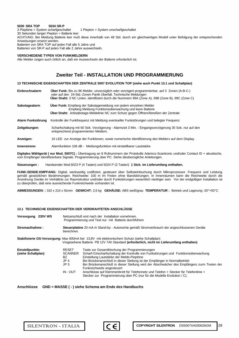
28SILENTRON - ITALIA COPYRIGHT SILENTRON DS5007XA030626GM
5030 SRA TOP 5034 SR-P3 Pieptöne = System scharfgeschaltet 1 Piepton = System unscharfgeschaltet30 Sekunden langer Piepton = Batterie leerACHTUNG: Bei Meldung Batterie leer muß diese innerhalb von 48 Std. durch ein gleichwertiges Modell unter Befolgung der entsprechendenAnweisungen ersetzt werden.Batterien von SRA TOP auf jeden Fall alle 5 Jahre undBatterien von SR-P auf jeden Fall alle 2 Jahre auswechseln.
VERSCHIEDENE TYPEN VON FUNKMELDERNAlle Melder zeigen auch örtlich an, daß ein Auswechseln der Batterie erforderlich ist.
Zweiter Teil - INSTALLATION UND PROGRAMMIERUNG
13 TECHNISCHE EIGENSCHAFTEN DER ZENTRALE 5007 EVOLUTION TOP (siehe auch Punkt 13.1 und Schaltplan)
Einbruchsalarm Über Funk: Bis zu 96 Melder, unverzüglich oder verzögert programmierbar, auf 3 Zonen (A-B-C-) oder auf den 24-Std.-Zonen Panik Überfall, Technische Meldungen Über Draht: 3 NC Linien, identifiziert durch die Nummern 99A (Zone A), 99B (Zone B), 99C (Zone C)
Sabotagealarm Über Funk: Empfang der Sabotagemeldung von jedem einzelnen Melder Empfang Meldung Funktionsüberwachung und leere Batterie Über Draht: Antisabotage-Meldelinie NC zum Schutz gegen Öffnen/Abreißen der Zentrale
Alarm Funkstörung Kontrolle der Funkfrequenz mit Meldung eventueller Funkstörungen und belegter Frequenz
Zeitgebungen: Scharfschaltung mit 60 Sek. Verzögerung - Alarmzeit 3 Min. - Eingangsverzögerung 30 Sek. nur auf denentsprechend programmierten Meldern.
Anzeigen: 16 LED zur Anzeige der Funktionen, sowie numerische Identifizierung des Melders auf dem Display.
Innensirene: Alarmfunktion 106 dB - Meldungsfunktion mit einstellbarer Lautstärke
Digitales Wählgerät ( nur Mod. 5007C) : Übertragung an 8 Rufnummern der Protokolle Ademco-Scantronic und/oder Contact ID + akustische,vom Empfänger identifizierbare Signale. Programmierung über PC. Siehe diesbezügliche Anleitungen.
Steuerungen : Handsender Mod.5023 P (4 Tasten) und 5024 P (3 Tasten) 1 Stck. im Lieferumfang enthalten.
FUNK-SENDE-EMPFANG: Digital, werksseitig codifiziert, gesteuert über Selbsteinbuchung durch Mikroprozessor. Frequenz und Leistunggemäß gesetzlichen Bestimmungen. Reichweite: 100 m im Freien ohne Bandstörungen. In Innenräumen kann die Reichweite durch dieAnordnung Geräte im Verhältnis zur Raumstruktur und/oder durch Funkstörungen wesentlich niedriger sein. Vor der endgültigen Installation istzu überprüfen, daß eine ausreichende Funkreichweite vorhanden ist.
ABMESSUNGEN: : 310 x 214 x 91mm GEWICHT: 2,6 kg GEHÄUSE: ABS weiß/grau TEMPERATUR : Betrieb und Lagerung -20°+50°C
13.1 TECHNISCHE EIGENSCHAFTEN DER VERDRAHTETEN ANSCHLÜSSE
Versorgung 230V WS Netzanschluß erst nach der Installation vornehmen. Programmierung und Test nur mit Batterie durchführen
Stromaufnahme : Steuerplatine 20 mA in Stand-by - Autonomie gemäß Stromverbrauch der angeschlossenen Geräte berechnen.
Stabilisierte GS-Versorgung: Max 600mA bei 13,8V mit elektronischem Schutz (siehe Schaltplan) Vorgesehene Batterie PB 12V 7Ah Standard (erforderlich, nicht im Lieferumfang enthalten)
Einstellpunkte: RESET Taste zur Gesamtlöschung der Programmierungen(siehe Schaltplan) SCANNER Scharf-/Unscharfschaltung der Kontrolle von Funkstörungen und Funktionsüberwachung
BZ Einstellung Lautstärke der Melde-PieptöneJP 4 Bei Brückenanschluß in dieser Stellung ist der Empfänger in NormalbetriebJP 5 Bei Brückenanschluß in dieser Stellung wird der Abschwächer des Empfängers zurm Testen der
Funkreichweite angesteuertIN - OUT Anschlüsse auf Klemmenbrett für Telefonnetz und Telefon + Stecker für Telefonlinie +
Stecker zur Programmierung über PC (nur für die Modelle Evolution / C).
Anschlüsse GND = MASSE ( - ) siehe Schema am Ende des Handbuchs

29SILENTRON - ITALIA COPYRIGHT SILENTRON DS5007XA030626GM
14 ZU BEACHTENDE VORSICHTSMASSNAHMEN FÜR EINE KORREKTE INSTALLATION (siehe Abb. 1)
Bei jeder Installation müssen die verschiedenen Ortsgegebenheiten berücksichtigt werden, daher sind Fachkenntnisse erforderlich.Installationsfehler können zu – den Geräten nicht zuzuschreibenden – Betriebsstörungen des Systems führen.Vor der Installation empfiehlt es sich, die Art und Anordnung der vorgesehenen drahtgebundenen und drahtlosen Melder und deren Aufteilungauf die 3 Zonen zu bestimmen (zwecks Teilscharfschaltung), sowie die Tabelle auf der letzten Seite auszufüllen. Melder und Handsender mitSonderfunktionen (24 Std.) müssen auf den entsprechenden Kanälen programmiert werden. Die Reichweite der Handsender ist veränderlich inAbhängigkeit von der Stellung und der Art, diese während der Übertragung in der Hand zu halten: Günstigste Stellungen bestimmen. Allefeststehenden Hindernisse verursachen Minderung der Funkreichweite. Zur Überprüfung der Signalstärke, Brücke von Position JP4 aufPosition JP5 versetzen und einwandfreien Empfang der Signale ermitteln. Es empfiehlt sich, ein Feldmeßgerät am Installtationsort der Zentralezu verwenden, wobei die empfangenen Signale wenigstens im gelben Bereich sein sollten. (Abb. 5). Bei nicht vorhandener Übertragung desSystems darf die vom Feldmeßgerät angezeigte Grundstörung den grünen Bereich nicht übersteigen.Verkabelung: Kabeldurchgänge für Sirenen, Telefonwählgeräte und so weiter vorsehen. Jedes Gerät muß gemäß Schaltplan an die Klemmenangeschlossen werden. Stromaufnahme der drahtgebundenen Geräte berechnen und ermitteln, daß der Gesamtwert die Kapazität desStromversorgers nicht überschreitet (max. 1A Spitzenlast – max. 600mA Dauerlast)
15 ANORDNUNG UND BEFESTIGUNG DER ZENTRALE (siehe Abb. 6)
Um den bestmöglichen Funkempfang zu erzielen, muß die Zentrale im Verhältnis zu Meldern und Sirenen “mittig” angeordnet sein. Sie kann innichtmetallischen Möbeln angebracht oder an der Wand befestigt werden, unter Berücksichtigung folgender Faktoren:
• Guter Funksignalempfang aller Melder und gute Übertragung an die Alarmvorrichtungen• Problemlose Verlegung der vorgesehenen Drahtverbindungen• Anbringung in einem wenigstens von einem räumlichen Melder geschützten Bereich• Hörbarkeit der Innensirene und der akustischen Meldungen (einstellbare Schallstärke)• Notwendigkeit der Anzeige von LEDs und Display.
ANMERKUNG: Die Anordnung der Geräte hat den Vorrang gegenüber von eventuellen ästhetischen Einschränkungen, die deneinwandfreien Betrieb des Systerms beeinträchtigen könnten.
LEGENDE ZENTRALENINNENRAUM
A = Befestigungspunkte B = BatterieanschlußC = Bleibatterie D = Reset-TasteE = Steckbrücke fÜr Scanner F = SabotagekontaktG = Sabotageschalteranschluss K = PieptonregulierungJ = Innensirene MX - MY - MZ KlemmleistenJP5 = Abschwächer RX EPROM = Programmierbarer Speicher
16 VORBEREITUNG ZUR PROGRAMMIERUNG
Das Einstellen zur Programmierung erfolgt auf zwei Weisen:1 Bei nicht angeschlossener Zentrale: Batterie einlegen.2 Bei angeschlossener Zentrale: TEST-Funktion einstellen, dann
Gehäuse öffnen, d.h. den Sabotagekontakt.
16.1 HANDSENDER UND TASTATUREN
Zur Programmierung ist mindestens ein Handsender PCK 3P oder 4P (Art.Nr. 5054 oder 5053P), mit weißer Taste, unerläßlich zurDurchführung einiger Maßnahmen, erforderlich. Dieser Handsender muß zuerst programmiert werden und dem Benutzer für die normalenSchaltungen zur Verfügung stehen, als wesentlicher Bestanteil der Anlage.Des weiteren sind zusätzliche 31 Stellen verfügbar, auf denen Handsender PCK jeden Typs programmiert werden können, sowie 32numerische, über Tastatur durchgeführte Codes mit 4 Ziffern. Jeder Code über Tastatur mit unterschiedlichen Ziffern besetzt eine eigenePosition, jeder Code kann auf verschiedenen Tastaturen verwendet werden.
16.2 PROGRAMMIERUNG DER MELDER (alle Modelle) - Die Zentrale muß auf “PROGRAMMIERUNG” eingestellt sein:
Wahl der Zone: Durch mehrmaliges Drücken der grünen Taste des bereits programmierten Handsenders PCK-P wird durch Aufleuchten derentsprechenden LED eine Zone bestimmt (A-B-C: PANIK – RAUB – TECHN. ALARME), auf der die Melder programmiert werden sollen.Wahl der Stellung: Jeder der 96 programmierbaren Melder wird einer numerischen Stellung zugeteilt, die automatisch auf dem Displayangezeigt wird – Beispiel A1 – und die sich ändert, wenn ein Melder programmiert wird – A2, A3, usw.Falls andere Stellungen als die automatisch angezeigte gewählt werden sollen, mehrmals die weiße Taste des Handsenders PCK-P drücken.Einstellung der Eingangsverzögerung: Jeder Melder löst einen Sofortalarm aus. Für eine Alarmverzögerung (30 Sekunden Festwert), vorProgrammierung des Melders rote Taste des Handsenders PCK-P drücken: Die LED EINGANGSVERZÖGERUNG leuchtet auf.UND-Funktion: Jede Stellung kann zwei Melder mit UND-Schaltung enthalten: In diesem Fall erfolgt ein Alarm, nur wenn dieser von beidenMeldern innerhalb von 30 Sekunden zwischen den zwei Übertragungen ausgelöst wird. Diese Funktion ist nützlich, um eventuelle falscheAlarme in schwierigen Situationen zu vermeiden. Zur Programmierung dieser Funktion, die Tasten rot-grün des Handsenders PCK-P vorProgrammierung des Melders drücken: Die LED “DOPPELMELDER” leuchtet auf

30SILENTRON - ITALIA COPYRIGHT SILENTRON DS5007XA030626GM
17 PROGRAMMIERUNGSABLAUF
1 Scanner durch Schließen der Brücke ansteuern. Die Sirene wird eventuelle Funkstörungen während der Programmierung melden.2 Eine Batterie Pb 12V 7 Ah (nicht im Lieferumfang) anschließen. Sie muß voll aufgeladen sein. 20 Sekunden zur Ausregelung des
Funkempfängers warten3 RESET-Taste zum Löschen eventueller Probeprogrammierungen drücken (Piepton).4 Die LED der Zentrale “PROGR-TEST” blinkt auf. Die Zentrale ist bereit zur PROGRAMMIERUNG.5 Lautstärke der Pieptöne nach Wunsch einstellen.6 Den mit der Zentrale gelieferten Handsender durch gleichzeitiges Drücken der roten und grünen Taste programmieren, bis die Bestätigung
durch einen Piepton erfolgt.7 Zur Programmierung der anderen Handsender (alle Modelle) grüne und rote Taste gleichzeitig wie oben drücken.8 Programmierung eventueller Codes über Tastatur: die 4 Ziffern eingeben, dann rote und grüne Taste gleichzeitig bis zur Bestätigung durch
einen Piepton drücken.9 Mit der grünen Taste Zone wählen, wo der erste Melder programmiert werden soll (Beispiel A: auf dem Display wird A1 angezeigt). Zum
Eingeben einer Eingangsverzögerung, rote Taste des Handsenders drücken (LED “EINGANGSVERZ.”) Zum Eingeben der “UND”Funktion, rote und grüne Taste gleichzeitig drücken (LED “DOPPELMELDER”)
10 Zugeteilte Nummer notieren und Melder durch Einlegen der Batterie programmieren: Ein Piepton der Zentrale bestätigt und das Displaygeht auf die folgende Stellung über. Falls die UND-Funktion vorgesehen ist, leuchtet die Nummer auf dem Display auf: Auch den zweitenMelder programmieren.
11 Die anderen Melder wie oben angeführt programmieren (Punkte 9 und 10). Zur Zuteilung von bestimmten Stellungen (nicht in Reihenfolge),dieselben durch Drücken der weißen Taste des Handsenders suchen
12 PANIKALARM: Panikzone auf Zentrale anwählen, Taste gelb oder blau des Handsenders wählen. Gewählte Taste 10 Sekunden langdrücken bis zur Bestätigung durch Piepton (Funktion 9.1).
13 ÜBERFALLALARM: Überfallzone auf Zentrale anwählen, Taste gelb oder blau des Handsenders wählen. Gewählte Taste 10 Sekundenlang drücken bis zur Bestätigung durch Piepton (Funktion 9.2).
14 Eventuelle Melder für technische Alarme auf der Zone “TECHN. ALARME” programmieren (Funktion 9.3).
Die durchgeführte Programmierung verbleibt auf der herausziehbaren EPROM-Platine auch nach Abstecken der Batterie und wird nur durchDrücken der RESET-Taste vollständig gelöscht. Die herausziehbare Platine kann beim Auswechseln der Zentrale übertragen werden. NachProgrammierung des Funkelements, Proben hinsichtlich eines einwandfreien Empfangs durchführen, indem die Brücke auf Position JP5gesteckt wird (siehe Schaltplan). Abschwächer RX durch erneutes Stecken der Brücke auf JP4 ausschalten und Wandbefestigung der Zentraleerst nach positivem Ergebnis durchführen. Danach eventuelle Melder und/oder drahtgebundene Alarmgeräte anschließen (siehe Schaltplan).
17.1 VERDRAHTETE GERÄTEDie Alarmkontakte der verdrahteten Melder werden an die Eingänge A-B-C angeschlossen und sind automatisch den Stellungen A99 – B99 –C99 zugeteilt. Ungenutzte Eingänge können offen bleiben. Verdrahtete Melder und Sirenen müssen, wie unter Punkt 13.1 beschrieben,angeschlossen werden.Anschlüsse überprüfen und Zentrale durch Anziehen der Deckelschraube schließen (Schließen Sabotagekontakt). Hierdurch wird automatischder Übergang von PROGRAMMIERUNG auf TEST erzielt.Der Alarm der drahtgebundenen Melder (Linie geöffnet) verursacht das Aufleuchten der LED der entsprechenden Zone und der Nummer 99 aufdem Display. Drahtgebundene Sirenen, Telefonwählgeräte und Melder müssen in der Folge bei Zentrale auf “Normalbetrieb” überprüft werden
17.2 NETZANSCHLUSSNetzanschluß mit Doppelisolierungskabel 2x1 qmm durchführen, unter Benutzung des entsprechenden, herausziehbaren Klemmenbrettes miteingebauter Sicherung (500mA). Die Kabel müssen an den vorgesehenen Stellen befestigtwerden, um ein unbeabsichtigtes Loslösen zu vermeiden und am Kabelende mit einemStecker für elektrische Steckdose versehen sein. Nach erfolgtem Anschluß, Deckel desKlemmenbretts 230V und dann die Zentrale schließen, danach den Stecker in die Steckdoseeinführen. Die aufleuchtende LED zeigt die vorhandene Stromversorgung und den Betriebdes Netzgeräts an.
18 PROGRAMMIERUNG DER ALARMGERÄTE • Sirenen und Telefonwählgeräte auf Selbsteinbuchung des Codes der Zentrale vorbereiten (siehe spezifische Anleitungen).• Zentrale scharf-, dann unscharf schalten ( durch vorübergehende Verbindung der Klemmen KEY und GND ) und auf Bestätigung durch
Piepton warten (Sirenen = sechs aufeinanderfolgende Pieptöne)
19 ÄNDERUNGEN ODER VARIANTEN AM SYSTEM (bei Zentrale auf Einstellung TEST)
Zusätzliche Handsender PCK und Codes von Tastatur: Vorgang vom Benutzer durchführbar (siehe Punkt 17.7).
Löschen von Handsendern (Es müssen alle PCK gelöscht und dann die benötigten programmiert werden): 10 Sekunden lang rote undgrüne Taste eines programmierten Handsenders gleichzeitig drücken. Ein langer Piepton bestätigt die erfolgte Löschung.
Löschen einzelner Handsender von Tastatur: Auf TEST übergehen, Code eingeben, rot und grün 10 Sekunden lang bis zum Endpieptondrücken
Zusatz/Löschung von Meldern: Zugriff zur PROGRAMMIERUNG durch Öffnen der Zentrale, dann können Stellung und Eigenschaft derMelder geändert werden. Zur Abänderung der Eingangsverzögerung wie während der Programmierung vorgehen (Punkt 16.2): Suche derStellung mit weißer Taste des Handsenders und Abänderung mit roter Taste. Für Änderungen der “UND”-Funktion müssen die Sensorengelöscht werden.Zum Löschen eines Melders: Suche der Stellung mit weißer Taste des Handsenders und 10 Sek. langes Drücken der roten und grünen Taste.
Auswechseln der Zentrale: Bei Beschädigung der Zentrale ist es möglich, diese - unter Sicherung der gesamten Programmierungsdaten derAnlage - durch das gleiche Modell zu ersetzen: Zentrale von der Netzversorgung abstecken, Eprom herausnehmen (siehe Schema) und in dieneue Zentrale einfügen.

31SILENTRON - ITALIA COPYRIGHT SILENTRON DS5007XA030626GM
1
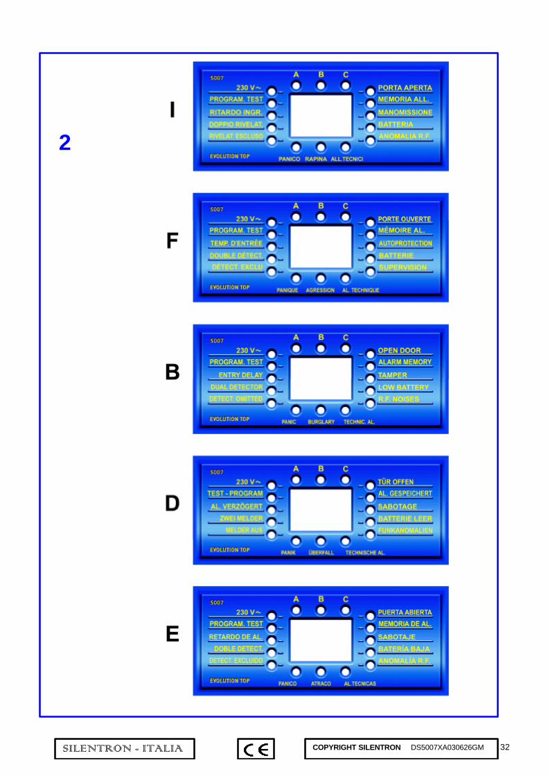
32SILENTRON - ITALIA COPYRIGHT SILENTRON DS5007XA030626GM
2
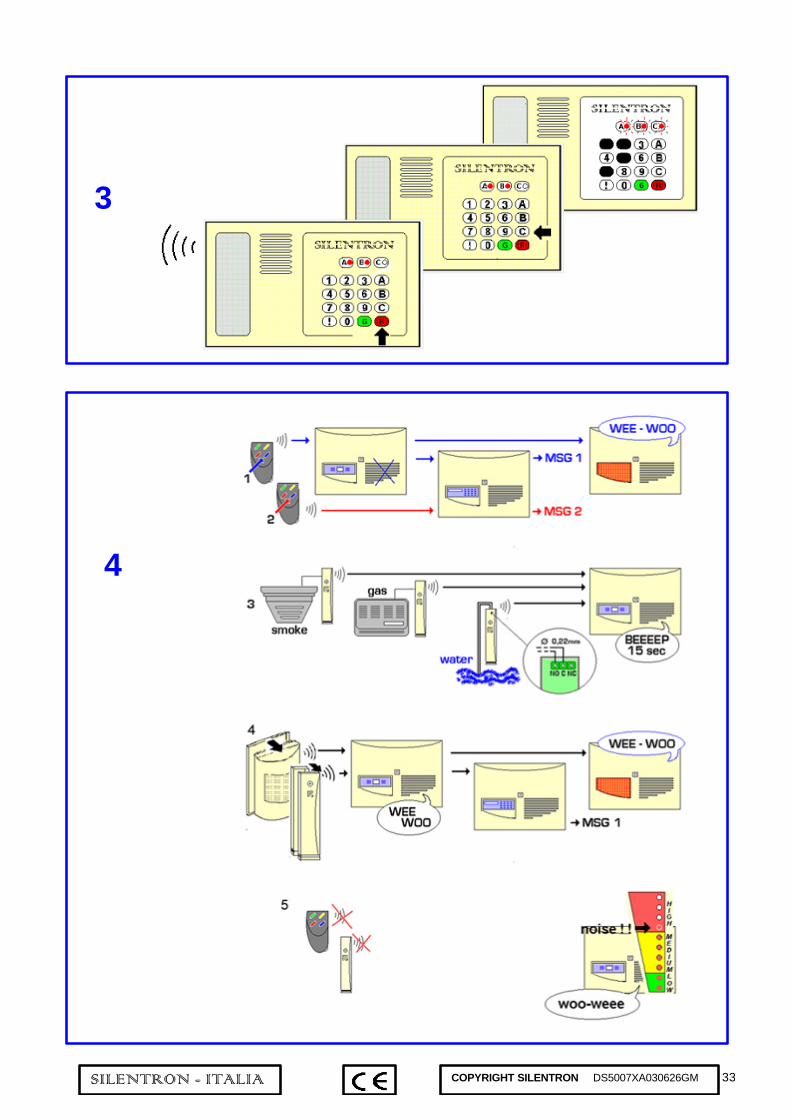
33SILENTRON - ITALIA COPYRIGHT SILENTRON DS5007XA030626GM
3
4

34SILENTRON - ITALIA COPYRIGHT SILENTRON DS5007XA030626GM
5
6

35SILENTRON - ITALIA COPYRIGHT SILENTRON DS5007XA030626GM
SCHEMA ELECTRIQUE ET LIAISONS
Bornier MX
+ AL alimentation détecteurs filaires 12V CC max 200 m+ OFF positif présent en arrêt pour reset détecteurs et sirènes+ SIR alimentation sirène intérieure 12V 500 mA en alarme+ SA alimentation sirène extérieure filaire 14,3V CC 200 mA+ N commande pos. sirène extérieure, à manquer en alarme
Bornier MY (uniquement réf /C)
OUT connexion deux fils téléphoneTerre connexion de terreIN connexion deux fils ligne téléphonique
Bornier MZ: les sorties NPN ferment à masse
C-NF-NO libre échange du relais d’alarme12 V 0,5 A.TMP sortie NPN alarme tamperON sortie NPN centrale en marcheBAT sortie NPN alarme batterie bassePAN sortie NPN alarme paniqueRAP sortie NPN alarme aggressionTEC sortie NPN alarme techniqueVIS sortie NPN alarme anomalie RF et supervisionKEY entrée mono-bistable pour clé filaireinA entrée NF d’alarme filaire groupe AinB entrée NF d’alarme filaire groupe BinC entrée NF d’alarme filaire groupe CinT entrée NF autoprotection filaire
SCHEMA ELETTRICO E COLLEGAMENTI
Morsettiera MX
+AL alimentaz. rivelatori via filo - 12V CC max 200mA+OFF positivo presente in OFF per reset rivelatori e sirene+SIR alimentazione sirena interna - 12V 500mA in allarme+SA alimentaz. sirena esterna via filo - 14,3V CC 200mA+N comando sirena esterna - positivo a mancare in allarme
Morsettiera MY (solo modelli 5007 C e 5008 C)
OUT collegamento dei 2 fili del telefonoterra collegamento di terraIN collegamento dei due fili della linea telefonica
Morsettiera MZ: le uscite NPN chiudono a massa
C-NC-NO scambio libero del relè di allarme 12V 0,5ATMP uscita NPN allarme tamperON uscita NPN centrale inseritaBAT uscita NPN allarme batteria bassaPAN uscita NPN allarme panicoRAP uscita NPN allarme rapinaTEC uscita NPN allarme tecnicoVIS uscita NPN allarme amomalia R.F. e supervisioneKEY ingresso mono-bistabile per chiave via filoinA ingresso NC di allarme via filo zona AinB ingresso NC di allarme via filo zona BinC ingresso NC di allarme via filo zona CinT ingresso NC di autoprotezione via filo

36SILENTRON - ITALIA COPYRIGHT SILENTRON DS5007XA030626GM
ELECTRICAL DIAGRAM AND CONNECTIONS
MX terminal board
+ AL wired detectors supplying - 12V CC max 200 mA+ OFF positive reset for detectors and sirens+ SIR inside siren supply – 12 V 500 mA in alarm+ SA wire outdoor siren supply – 14,3 CC 200 mA+ N outdoor siren service – positive to fall in alarm
MY terminal board (5007C and 5008C only)
OUT connection of the two telephone wiresGround ground connectionIN connection of the two wires of telephone line
MZ terminal board : NPN outputs close towards ground
C-NC-NO alarm relay free exchange 12 V 0,5 ATMP NPN output tamper alarmON NPN output control unit armedBAT NPN output low-batteryPAN NPN output panic alarmRAP NPN output burglar alarmTEC NPN output technical alarmVIS NPN output RF trouble and supervision alarmKEY mono-bistable input for wired keyinA wire-alarm NC input group AinB wire-alarm NC input group BinC wire-alarm NC input group CinT wire-self-protection NC input
SCHALTPLAN DER ANSCHLÜSSE MIT LEGENDE
Klemmenbrett MX+AL Versorgung verdrahteter Melder - 12V GS max 200mA+OFF Positiv bei OFF zum Reset von Meldern und Sirenen+SIR Versorgung Innensirene - 12V 500mA bei Alarm+SA Versorgung verdrahtete Außensirene -14,3V DS 200 mA+N Steuerung Außensirene – kein Positiv bei Alarm
Klemmenbrett MY (nur Modelle 5007 C und 5008 C)OUT Anschluß der 2 Telefondrähteterra ErdungIN Anschluß der 2 Drähte der Telefonlinie
Klemmenbrett MZ: Erdschluß Ausgänge NPNC-NC-NO Freier Austausch Alarmrelais12V 0,5ATMP Ausgang NPN SabotagealarmON Ausgang NPN Zentrale scharfgeschaltetBAT Ausgang NPN Alarm Batterie leerPAN Ausgang NPN PanikalarmRAP Ausgang NPN ÜberfallalarmTEC Ausgang NPN Technischer AlarmVIS Ausgang NPN Funkstörungen und
FunktionsüberwachungKEY mono-/bistabiler Eingang für verdrahteten SchlüsselinA Verdrahteter Alarmeingang NC Zone AinB Verdrahteter Alarmeingang NC Zone BinC Verdrahteter Alarmeingang NC Zone CinT Verdrahteter Selbstschutzeingang NC
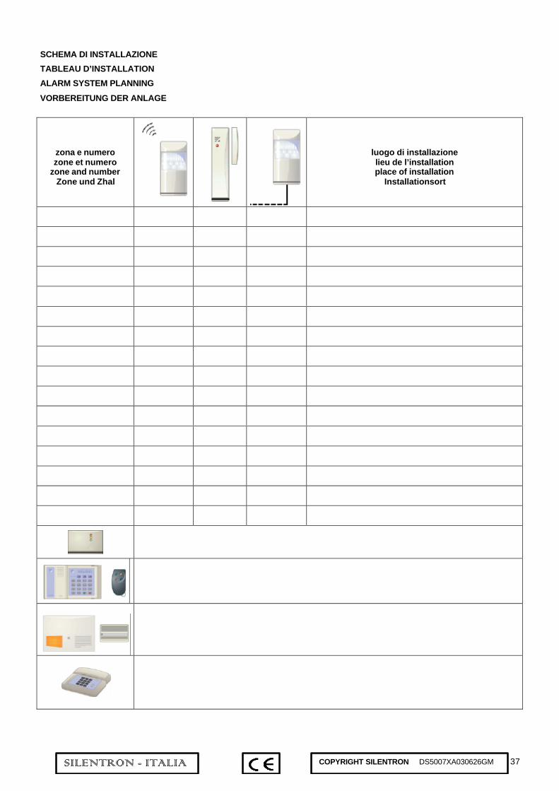
37SILENTRON - ITALIA COPYRIGHT SILENTRON DS5007XA030626GM
SCHEMA DI INSTALLAZIONE
TABLEAU D’INSTALLATION
ALARM SYSTEM PLANNING
VORBEREITUNG DER ANLAGE
zona e numerozone et numero
zone and numberZone und Zhal
luogo di installazionelieu de l’installationplace of installation
Installationsort

38SILENTRON - ITALIA COPYRIGHT SILENTRON DS5007XA030626GM

39SILENTRON - ITALIA COPYRIGHT SILENTRON DS5007XA030626GM

40SILENTRON - ITALIA COPYRIGHT SILENTRON DS5007XA030626GM