CACCIALANZA C. S.p.A. ANTINCENDIO SICUREZZA …
24
CACCIALANZA & C. S.p.A. ANTINCENDIO SICUREZZA ANTINQUINAMENTO 21-04-2010 rev.1 P_mon_1a_E page 1 TECHNICAL FEATURES of ELECTRIC REMOTE CONTROLLED MONITORS SYSTEMS
Transcript of CACCIALANZA C. S.p.A. ANTINCENDIO SICUREZZA …

CACCIALANZA & C. S.p.A. A N T I N C E N D I O S I C U R E Z Z A A N T I N Q U I N A M E N T O
21-04-2010 rev.1 P_mon_1a_E page 1
TECHNICAL FEATURES
of
ELECTRIC REMOTE CONTROLLED
MONITORS SYSTEMS
CACCIALANZA & C. S.p.A. A N T I N C E N D I O S I C U R E Z Z A A N T I N Q U I N A M E N T O
21-04-2010 rev.1 P_mon_1a_E page 2
CACCIALANZA & C. S.p.A. A N T I N C E N D I O S I C U R E Z Z A A N T I N Q U I N A M E N T O
21-04-2010 rev.1 P_mon_1a_E page 3
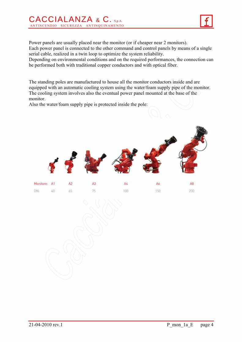
General description The remote controlled monitors are available with foam/water flowrates from 50 up to 30.000 lt/min. and consequently these are the possible flowrates of the systems with Caccialanza electric remote controlled monitors. The monitors are manufactured in 6 different types: A1, A2, A3, A4, A6 and A8. The monitor protection degree is IP 65. The monitors A3, A4, A6 and A8 types are available also in Ex-proof execution for mounting in hazardous areas where explosions may be caused either by gas or powder. The whole monitor system can be realized with the same max. protection degree as the monitor one. A monitor system consists of the required number of monitors, their standing poles (if the monitors are required in elevated position) and the command and control panels. The panel types are the following ones: - Power panels - - Power panels with local control devices - - Remote control panels - - Self standing remote control panels - - Portable remote control panels with cable - - Portable radio remote control panels. Caccialanza remote controlled monitor systems are always designed to minimize the number of electric cables required for connection, thus reaching the double purpose to maximize operating safety and to minimize total costs for realization and maintenance of the system (with total costs we mean not only costs of the fire fighting components of the system, but also costs of the required cables, costs of the civil and mechanical works for their protection in case of fire and costs of installation of all the components). Therefore, for all the actuators of all the monitor types a single cable (resistant to flames for 180 minutes and to acids) is enough to perform both power and control functions. For monitors A1 and A2 types a single cable (resistant to flames for 180 minutes and to acids) is even enough to perform power and control functions of all the functions of all the monitor actuators, valves included. All the remote controlled monitor system components are manufactured according to the European directives and are EC marked. For Ex-proof systems European directives ATEX are applied and all the electric components are certified by a notified body, in addition to the manufacturer's declaration of conformity.
CACCIALANZA & C. S.p.A. A N T I N C E N D I O S I C U R E Z Z A A N T I N Q U I N A M E N T O
21-04-2010 rev.1 P_mon_1a_E page 4
Power panels are usually placed near the monitor (or if cheaper near 2 monitors). Each power panel is connected to the other command and control panels by means of a single serial cable, realized in a twin loop to optimize the system reliability. Depending on environmental conditions and on the required performances, the connection can be performed both with traditional copper conductors and with optical fiber. The standing poles are manufactured to house all the monitor conductors inside and are equipped with an automatic cooling system using the water/foam supply pipe of the monitor. The cooling system involves also the eventual power panel mounted at the base of the monitor. Also the water/foam supply pipe is protected inside the pole:
CACCIALANZA & C. S.p.A. A N T I N C E N D I O S I C U R E Z Z A A N T I N Q U I N A M E N T O
21-04-2010 rev.1 P_mon_1a_E page 5
Monitors
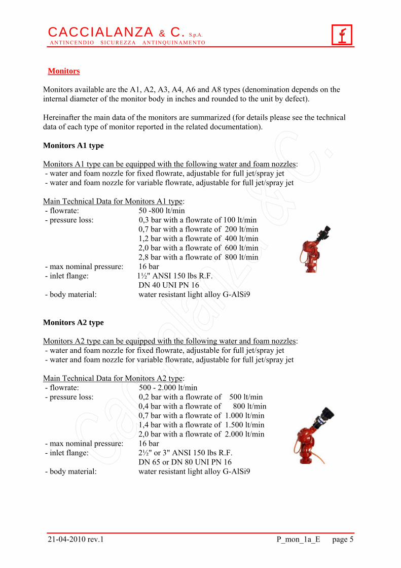
Monitors available are the A1, A2, A3, A4, A6 and A8 types (denomination depends on the internal diameter of the monitor body in inches and rounded to the unit by defect). Hereinafter the main data of the monitors are summarized (for details please see the technical data of each type of monitor reported in the related documentation). Monitors A1 type Monitors A1 type can be equipped with the following water and foam nozzles: - water and foam nozzle for fixed flowrate, adjustable for full jet/spray jet - water and foam nozzle for variable flowrate, adjustable for full jet/spray jet Main Technical Data for Monitors A1 type: - flowrate: 50 -800 lt/min - pressure loss: 0,3 bar with a flowrate of 100 lt/min 0,7 bar with a flowrate of 200 lt/min 1,2 bar with a flowrate of 400 lt/min 2,0 bar with a flowrate of 600 lt/min 2,8 bar with a flowrate of 800 lt/min - max nominal pressure: 16 bar - inlet flange: 1½" ANSI 150 lbs R.F. DN 40 UNI PN 16 - body material: water resistant light alloy G-AlSi9
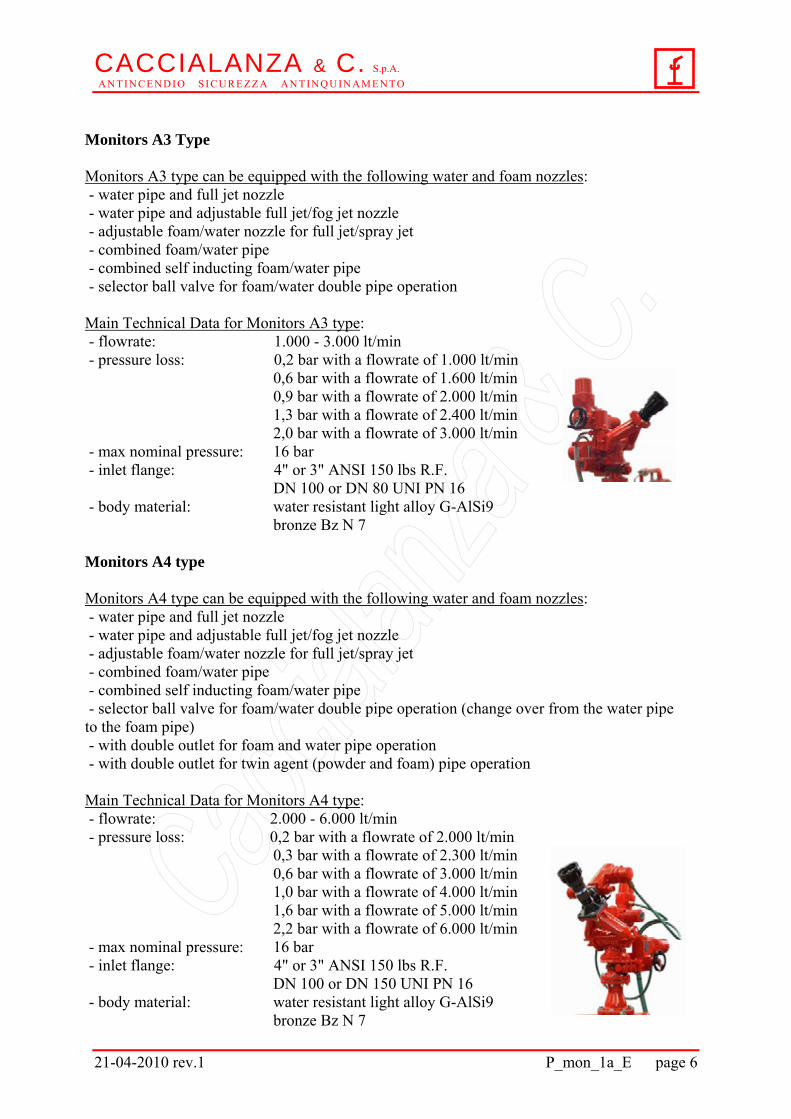
Monitors A2 type Monitors A2 type can be equipped with the following water and foam nozzles: - water and foam nozzle for fixed flowrate, adjustable for full jet/spray jet - water and foam nozzle for variable flowrate, adjustable for full jet/spray jet Main Technical Data for Monitors A2 type: - flowrate: 500 - 2.000 lt/min - pressure loss: 0,2 bar with a flowrate of 500 lt/min 0,4 bar with a flowrate of 800 lt/min 0,7 bar with a flowrate of 1.000 lt/min 1,4 bar with a flowrate of 1.500 lt/min 2,0 bar with a flowrate of 2.000 lt/min - max nominal pressure: 16 bar - inlet flange: 2½" or 3" ANSI 150 lbs R.F. DN 65 or DN 80 UNI PN 16 - body material: water resistant light alloy G-AlSi9
CACCIALANZA & C. S.p.A. A N T I N C E N D I O S I C U R E Z Z A A N T I N Q U I N A M E N T O
21-04-2010 rev.1 P_mon_1a_E page 6
Monitors A3 Type Monitors A3 type can be equipped with the following water and foam nozzles: - water pipe and full jet nozzle - water pipe and adjustable full jet/fog jet nozzle - adjustable foam/water nozzle for full jet/spray jet - combined foam/water pipe - combined self inducting foam/water pipe - selector ball valve for foam/water double pipe operation Main Technical Data for Monitors A3 type: - flowrate: 1.000 - 3.000 lt/min - pressure loss: 0,2 bar with a flowrate of 1.000 lt/min 0,6 bar with a flowrate of 1.600 lt/min 0,9 bar with a flowrate of 2.000 lt/min 1,3 bar with a flowrate of 2.400 lt/min 2,0 bar with a flowrate of 3.000 lt/min - max nominal pressure: 16 bar - inlet flange: 4" or 3" ANSI 150 lbs R.F. DN 100 or DN 80 UNI PN 16 - body material: water resistant light alloy G-AlSi9 bronze Bz N 7
Monitors A4 type Monitors A4 type can be equipped with the following water and foam nozzles: - water pipe and full jet nozzle - water pipe and adjustable full jet/fog jet nozzle - adjustable foam/water nozzle for full jet/spray jet - combined foam/water pipe - combined self inducting foam/water pipe - selector ball valve for foam/water double pipe operation (change over from the water pipe to the foam pipe) - with double outlet for foam and water pipe operation - with double outlet for twin agent (powder and foam) pipe operation Main Technical Data for Monitors A4 type: - flowrate: 2.000 - 6.000 lt/min - pressure loss: 0,2 bar with a flowrate of 2.000 lt/min 0,3 bar with a flowrate of 2.300 lt/min 0,6 bar with a flowrate of 3.000 lt/min 1,0 bar with a flowrate of 4.000 lt/min 1,6 bar with a flowrate of 5.000 lt/min
2,2 bar with a flowrate of 6.000 lt/min - max nominal pressure: 16 bar - inlet flange: 4" or 3" ANSI 150 lbs R.F. DN 100 or DN 150 UNI PN 16 - body material: water resistant light alloy G-AlSi9 bronze Bz N 7
CACCIALANZA & C. S.p.A. A N T I N C E N D I O S I C U R E Z Z A A N T I N Q U I N A M E N T O
21-04-2010 rev.1 P_mon_1a_E page 7
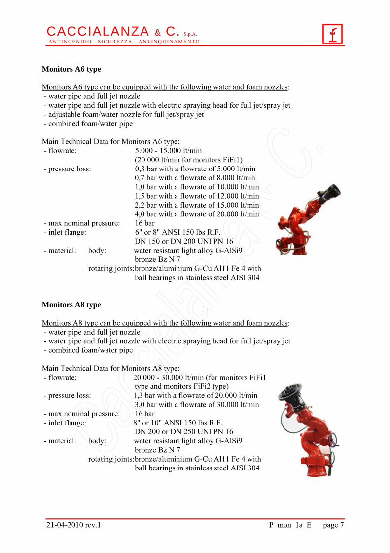
Monitors A6 type Monitors A6 type can be equipped with the following water and foam nozzles: - water pipe and full jet nozzle - water pipe and full jet nozzle with electric spraying head for full jet/spray jet - adjustable foam/water nozzle for full jet/spray jet - combined foam/water pipe Main Technical Data for Monitors A6 type: - flowrate: 5.000 - 15.000 lt/min (20.000 lt/min for monitors FiFi1) - pressure loss: 0,3 bar with a flowrate of 5.000 lt/min 0,7 bar with a flowrate of 8.000 lt/min 1,0 bar with a flowrate of 10.000 lt/min 1,5 bar with a flowrate of 12.000 lt/min
2,2 bar with a flowrate of 15.000 lt/min 4,0 bar with a flowrate of 20.000 lt/min
- max nominal pressure: 16 bar - inlet flange: 6" or 8" ANSI 150 lbs R.F. DN 150 or DN 200 UNI PN 16 - material: body: water resistant light alloy G-AlSi9 bronze Bz N 7
rotating joints: bronze/aluminium G-Cu Al11 Fe 4 with ball bearings in stainless steel AISI 304
Monitors A8 type Monitors A8 type can be equipped with the following water and foam nozzles: - water pipe and full jet nozzle - water pipe and full jet nozzle with electric spraying head for full jet/spray jet - combined foam/water pipe Main Technical Data for Monitors A8 type: - flowrate: 20.000 - 30.000 lt/min (for monitors FiFi1 type and monitors FiFi2 type) - pressure loss: 1,3 bar with a flowrate of 20.000 lt/min 3,0 bar with a flowrate of 30.000 lt/min - max nominal pressure: 16 bar - inlet flange: 8" or 10" ANSI 150 lbs R.F. DN 200 or DN 250 UNI PN 16 - material: body: water resistant light alloy G-AlSi9 bronze Bz N 7
rotating joints: bronze/aluminium G-Cu Al11 Fe 4 with ball bearings in stainless steel AISI 304
CACCIALANZA & C. S.p.A. A N T I N C E N D I O S I C U R E Z Z A A N T I N Q U I N A M E N T O
21-04-2010 rev.1 P_mon_1a_E page 8
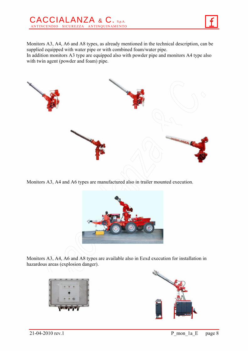
Monitors A3, A4, A6 and A8 types, as already mentioned in the technical description, can be supplied equipped with water pipe or with combined foam/water pipe. In addition monitors A3 type are equipped also with powder pipe and monitors A4 type also with twin agent (powder and foam) pipe. Monitors A3, A4 and A6 types are manufactured also in trailer mounted execution.
Monitors A3, A4, A6 and A8 types are available also in Eexd execution for installation in hazardous areas (explosion danger).
CACCIALANZA & C. S.p.A. A N T I N C E N D I O S I C U R E Z Z A A N T I N Q U I N A M E N T O
21-04-2010 rev.1 P_mon_1a_E page 9
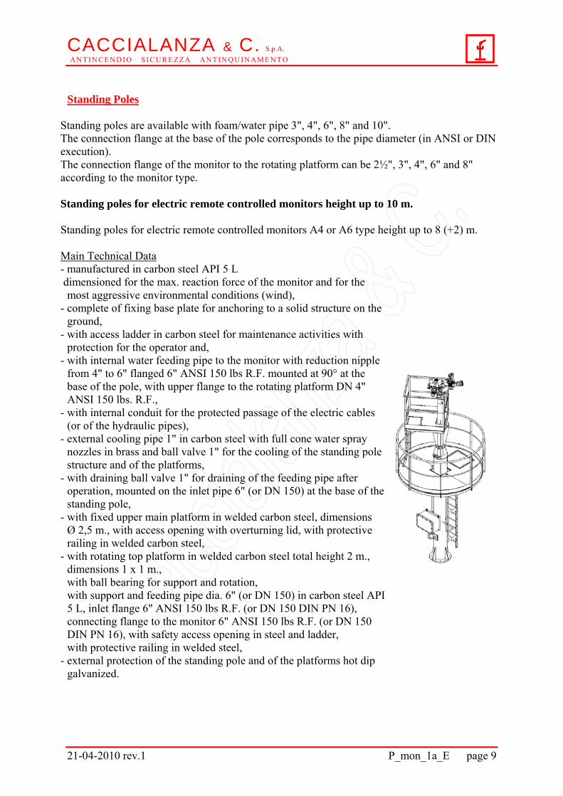
Standing Poles
Standing poles are available with foam/water pipe 3", 4", 6", 8" and 10". The connection flange at the base of the pole corresponds to the pipe diameter (in ANSI or DIN execution). The connection flange of the monitor to the rotating platform can be 2½", 3", 4", 6" and 8" according to the monitor type. Standing poles for electric remote controlled monitors height up to 10 m. Standing poles for electric remote controlled monitors A4 or A6 type height up to 8 (+2) m. Main Technical Data - manufactured in carbon steel API 5 L dimensioned for the max. reaction force of the monitor and for the
most aggressive environmental conditions (wind), - complete of fixing base plate for anchoring to a solid structure on the
ground, - with access ladder in carbon steel for maintenance activities with
protection for the operator and, - with internal water feeding pipe to the monitor with reduction nipple
from 4" to 6" flanged 6" ANSI 150 lbs R.F. mounted at 90° at the base of the pole, with upper flange to the rotating platform DN 4" ANSI 150 lbs. R.F.,
- with internal conduit for the protected passage of the electric cables (or of the hydraulic pipes),
- external cooling pipe 1" in carbon steel with full cone water spray nozzles in brass and ball valve 1" for the cooling of the standing pole structure and of the platforms,
- with draining ball valve 1" for draining of the feeding pipe after operation, mounted on the inlet pipe 6" (or DN 150) at the base of the standing pole,
- with fixed upper main platform in welded carbon steel, dimensions Ø 2,5 m., with access opening with overturning lid, with protective railing in welded carbon steel,
- with rotating top platform in welded carbon steel total height 2 m., dimensions 1 x 1 m., with ball bearing for support and rotation, with support and feeding pipe dia. 6" (or DN 150) in carbon steel API 5 L, inlet flange 6" ANSI 150 lbs R.F. (or DN 150 DIN PN 16), connecting flange to the monitor 6" ANSI 150 lbs R.F. (or DN 150 DIN PN 16), with safety access opening in steel and ladder, with protective railing in welded steel,
- external protection of the standing pole and of the platforms hot dip galvanized.
CACCIALANZA & C. S.p.A. A N T I N C E N D I O S I C U R E Z Z A A N T I N Q U I N A M E N T O
21-04-2010 rev.1 P_mon_1a_E page 10
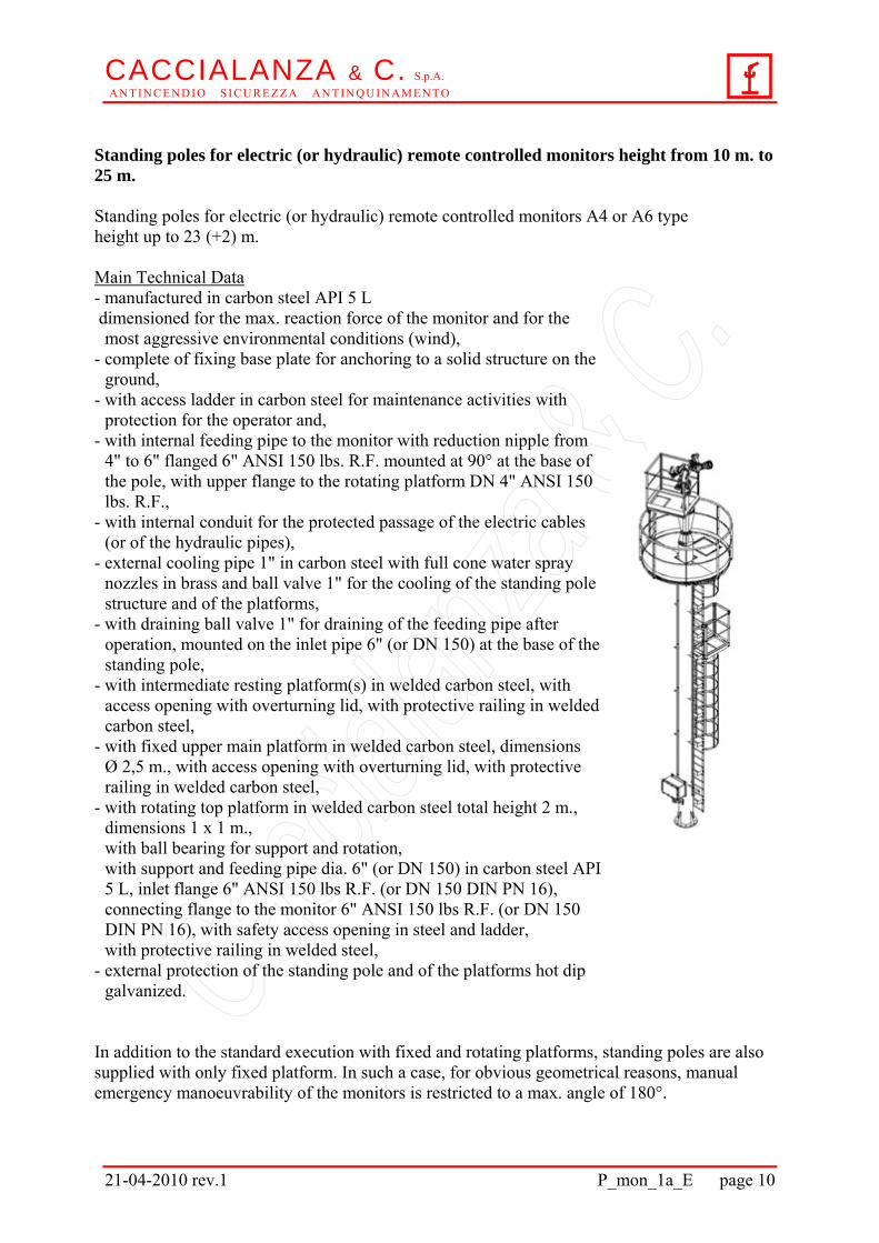
Standing poles for electric (or hydraulic) remote controlled monitors height from 10 m. to 25 m. Standing poles for electric (or hydraulic) remote controlled monitors A4 or A6 type height up to 23 (+2) m. Main Technical Data - manufactured in carbon steel API 5 L dimensioned for the max. reaction force of the monitor and for the
most aggressive environmental conditions (wind), - complete of fixing base plate for anchoring to a solid structure on the
ground, - with access ladder in carbon steel for maintenance activities with
protection for the operator and, - with internal feeding pipe to the monitor with reduction nipple from
4" to 6" flanged 6" ANSI 150 lbs. R.F. mounted at 90° at the base of the pole, with upper flange to the rotating platform DN 4" ANSI 150 lbs. R.F.,
- with internal conduit for the protected passage of the electric cables (or of the hydraulic pipes),
- external cooling pipe 1" in carbon steel with full cone water spray nozzles in brass and ball valve 1" for the cooling of the standing pole structure and of the platforms,
- with draining ball valve 1" for draining of the feeding pipe after operation, mounted on the inlet pipe 6" (or DN 150) at the base of the standing pole,
- with intermediate resting platform(s) in welded carbon steel, with access opening with overturning lid, with protective railing in welded carbon steel,
- with fixed upper main platform in welded carbon steel, dimensions Ø 2,5 m., with access opening with overturning lid, with protective railing in welded carbon steel,
- with rotating top platform in welded carbon steel total height 2 m., dimensions 1 x 1 m., with ball bearing for support and rotation, with support and feeding pipe dia. 6" (or DN 150) in carbon steel API 5 L, inlet flange 6" ANSI 150 lbs R.F. (or DN 150 DIN PN 16), connecting flange to the monitor 6" ANSI 150 lbs R.F. (or DN 150 DIN PN 16), with safety access opening in steel and ladder, with protective railing in welded steel,
- external protection of the standing pole and of the platforms hot dip galvanized.
In addition to the standard execution with fixed and rotating platforms, standing poles are also supplied with only fixed platform. In such a case, for obvious geometrical reasons, manual emergency manoeuvrability of the monitors is restricted to a max. angle of 180°.
CACCIALANZA & C. S.p.A. A N T I N C E N D I O S I C U R E Z Z A A N T I N Q U I N A M E N T O
21-04-2010 rev.1 P_mon_1a_E page 11
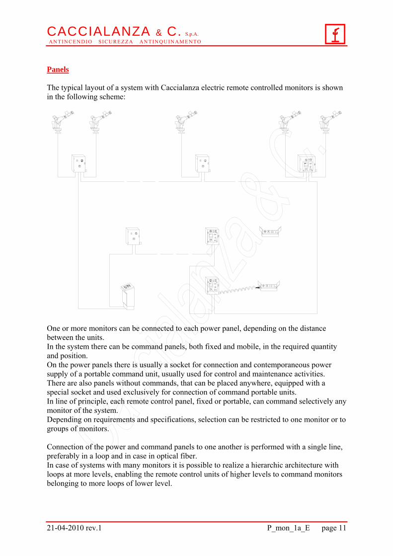
Panels The typical layout of a system with Caccialanza electric remote controlled monitors is shown in the following scheme:
One or more monitors can be connected to each power panel, depending on the distance between the units. In the system there can be command panels, both fixed and mobile, in the required quantity and position. On the power panels there is usually a socket for connection and contemporaneous power supply of a portable command unit, usually used for control and maintenance activities. There are also panels without commands, that can be placed anywhere, equipped with a special socket and used exclusively for connection of command portable units. In line of principle, each remote control panel, fixed or portable, can command selectively any monitor of the system. Depending on requirements and specifications, selection can be restricted to one monitor or to groups of monitors. Connection of the power and command panels to one another is performed with a single line, preferably in a loop and in case in optical fiber. In case of systems with many monitors it is possible to realize a hierarchic architecture with loops at more levels, enabling the remote control units of higher levels to command monitors belonging to more loops of lower level.
CACCIALANZA & C. S.p.A. A N T I N C E N D I O S I C U R E Z Z A A N T I N Q U I N A M E N T O
21-04-2010 rev.1 P_mon_1a_E page 12
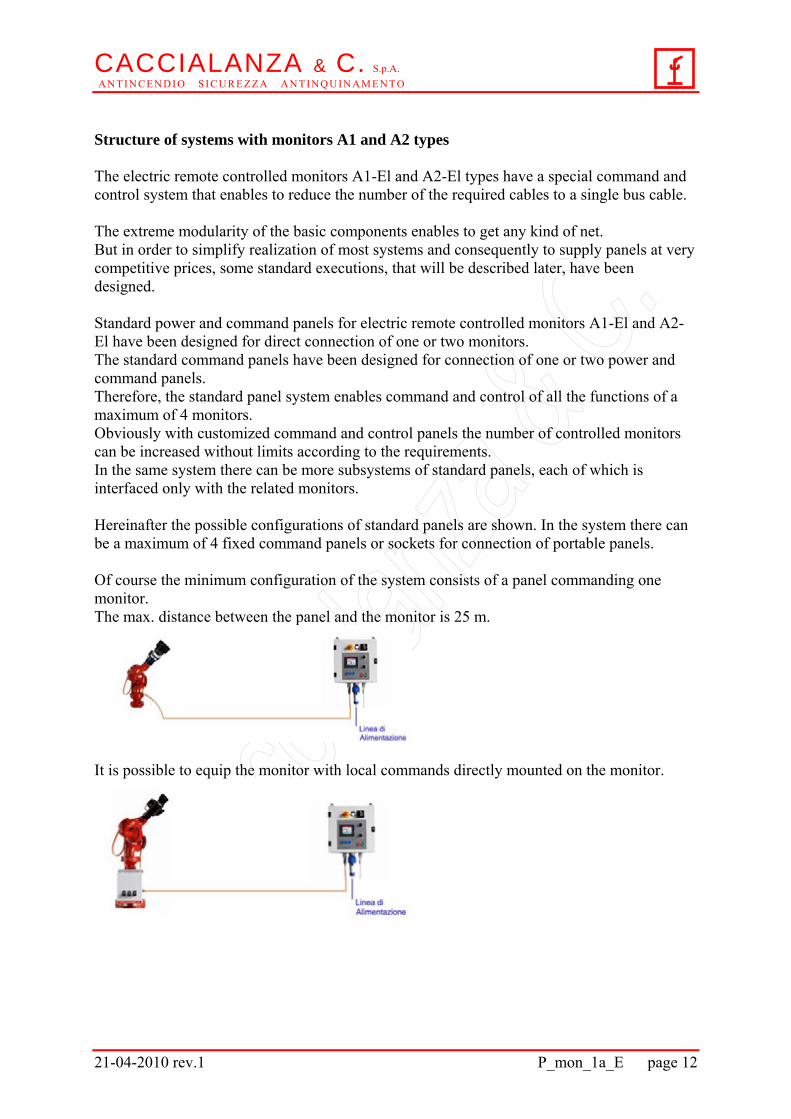
Structure of systems with monitors A1 and A2 types The electric remote controlled monitors A1-El and A2-El types have a special command and control system that enables to reduce the number of the required cables to a single bus cable. The extreme modularity of the basic components enables to get any kind of net. But in order to simplify realization of most systems and consequently to supply panels at very competitive prices, some standard executions, that will be described later, have been designed. Standard power and command panels for electric remote controlled monitors A1-El and A2-El have been designed for direct connection of one or two monitors. The standard command panels have been designed for connection of one or two power and command panels. Therefore, the standard panel system enables command and control of all the functions of a maximum of 4 monitors. Obviously with customized command and control panels the number of controlled monitors can be increased without limits according to the requirements. In the same system there can be more subsystems of standard panels, each of which is interfaced only with the related monitors. Hereinafter the possible configurations of standard panels are shown. In the system there can be a maximum of 4 fixed command panels or sockets for connection of portable panels. Of course the minimum configuration of the system consists of a panel commanding one monitor. The max. distance between the panel and the monitor is 25 m.
It is possible to equip the monitor with local commands directly mounted on the monitor.
CACCIALANZA & C. S.p.A. A N T I N C E N D I O S I C U R E Z Z A A N T I N Q U I N A M E N T O
21-04-2010 rev.1 P_mon_1a_E page 13
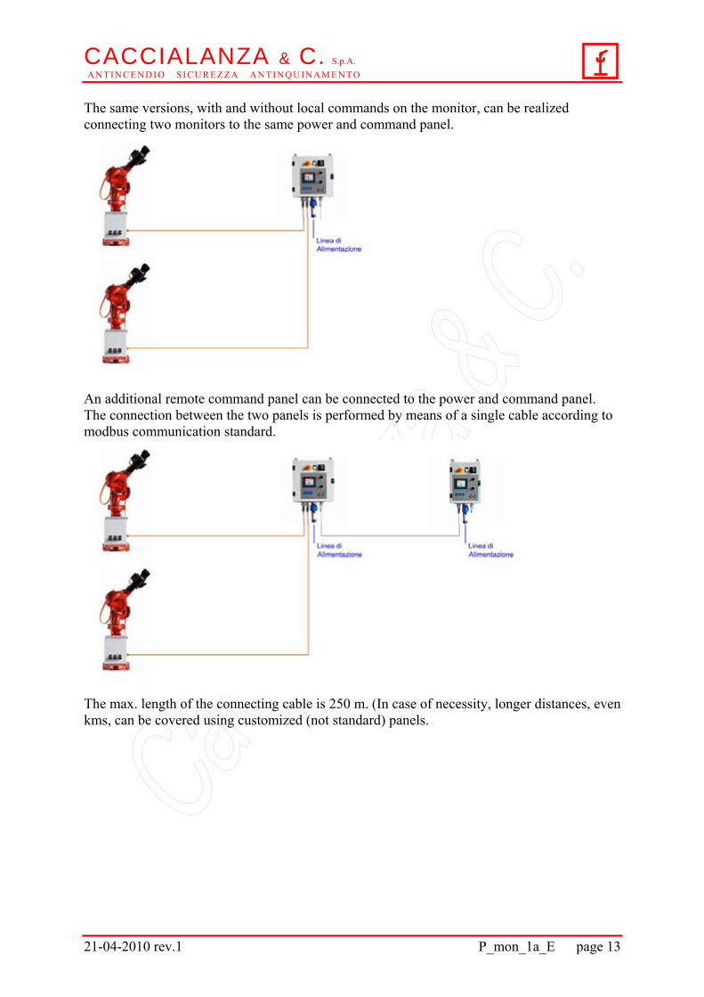
The same versions, with and without local commands on the monitor, can be realized connecting two monitors to the same power and command panel.
An additional remote command panel can be connected to the power and command panel. The connection between the two panels is performed by means of a single cable according to modbus communication standard.
The max. length of the connecting cable is 250 m. (In case of necessity, longer distances, even kms, can be covered using customized (not standard) panels.
CACCIALANZA & C. S.p.A. A N T I N C E N D I O S I C U R E Z Z A A N T I N Q U I N A M E N T O
21-04-2010 rev.1 P_mon_1a_E page 14
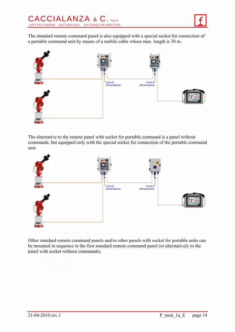
The standard remote command panel is also equipped with a special socket for connection of a portable command unit by means of a mobile cable whose max. length is 30 m.
The alternative to the remote panel with socket for portable command is a panel without commands, but equipped only with the special socket for connection of the portable command unit.
Other standard remote command panels and/or other panels with socket for portable units can be mounted in sequence to the first standard remote command panel (or alternatively to the panel with socket without commands).
CACCIALANZA & C. S.p.A. A N T I N C E N D I O S I C U R E Z Z A A N T I N Q U I N A M E N T O
21-04-2010 rev.1 P_mon_1a_E page 15
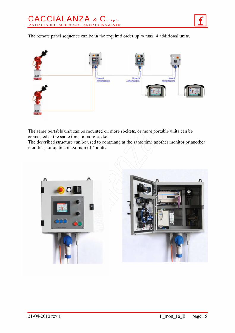
The remote panel sequence can be in the required order up to max. 4 additional units.
The same portable unit can be mounted on more sockets, or more portable units can be connected at the same time to more sockets. The described structure can be used to command at the same time another monitor or another monitor pair up to a maximum of 4 units.
CACCIALANZA & C. S.p.A. A N T I N C E N D I O S I C U R E Z Z A A N T I N Q U I N A M E N T O
21-04-2010 rev.1 P_mon_1a_E page 16
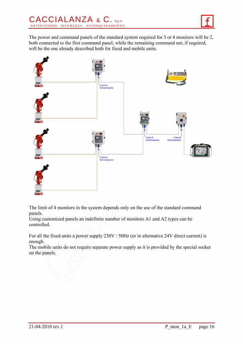
The power and command panels of the standard system required for 3 or 4 monitors will be 2, both connected to the first command panel; while the remaining command net, if required, will be the one already described both for fixed and mobile units.
The limit of 4 monitors in the system depends only on the use of the standard command panels. Using customized panels an indefinite number of monitors A1 and A2 types can be controlled. For all the fixed units a power supply 230V / 50Hz (or in alternative 24V direct current) is enough. The mobile units do not require separate power supply as it is provided by the special socket on the panels.
CACCIALANZA & C. S.p.A. A N T I N C E N D I O S I C U R E Z Z A A N T I N Q U I N A M E N T O
21-04-2010 rev.1 P_mon_1a_E page 17
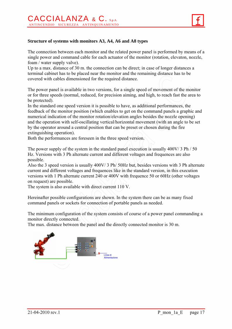
Structure of systems with monitors A3, A4, A6 and A8 types The connection between each monitor and the related power panel is performed by means of a single power and command cable for each actuator of the monitor (rotation, elevaton, nozzle, foam / water supply valve). Up to a max. distance of 30 m. the connection can be direct; in case of longer distances a terminal cabinet has to be placed near the monitor and the remaining distance has to be covered with cables dimensioned for the required distance. The power panel is available in two versions, for a single speed of movement of the monitor or for three speeds (normal, reduced, for precision aiming, and high, to reach fast the area to be protected). In the standard one speed version it is possible to have, as additional performances, the feedback of the monitor position (which enables to get on the command panels a graphic and numerical indication of the monitor rotation/elevation angles besides the nozzle opening) and the operation with self-oscillating vertical/horizontal movement (with an angle to be set by the operator around a central position that can be preset or chosen during the fire extinguishing operation). Both the performances are foreseen in the three speed version. The power supply of the system in the standard panel execution is usually 400V/ 3 Ph / 50 Hz. Versions with 3 Ph alternate current and different voltages and frequences are also possible. Also the 3 speed version is usually 400V/ 3 Ph/ 50Hz but, besides versions with 3 Ph alternate current and different voltages and frequences like in the standard version, in this execution versions with 1 Ph alternate current 240 or 400V with frequence 50 or 60Hz (other voltages on request) are possible. The system is also available with direct current 110 V. Hereinafter possible configurations are shown. In the system there can be as many fixed command panels or sockets for connection of portable panels as needed. The minimum configuration of the system consists of course of a power panel commanding a monitor directly connected. The max. distance between the panel and the directly connected monitor is 30 m.
CACCIALANZA & C. S.p.A. A N T I N C E N D I O S I C U R E Z Z A A N T I N Q U I N A M E N T O
21-04-2010 rev.1 P_mon_1a_E page 18
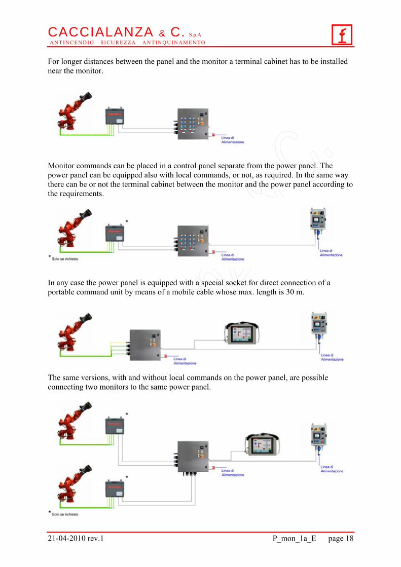
For longer distances between the panel and the monitor a terminal cabinet has to be installed near the monitor.
Monitor commands can be placed in a control panel separate from the power panel. The power panel can be equipped also with local commands, or not, as required. In the same way there can be or not the terminal cabinet between the monitor and the power panel according to the requirements.
In any case the power panel is equipped with a special socket for direct connection of a portable command unit by means of a mobile cable whose max. length is 30 m.
The same versions, with and without local commands on the power panel, are possible connecting two monitors to the same power panel.
CACCIALANZA & C. S.p.A. A N T I N C E N D I O S I C U R E Z Z A A N T I N Q U I N A M E N T O
21-04-2010 rev.1 P_mon_1a_E page 19
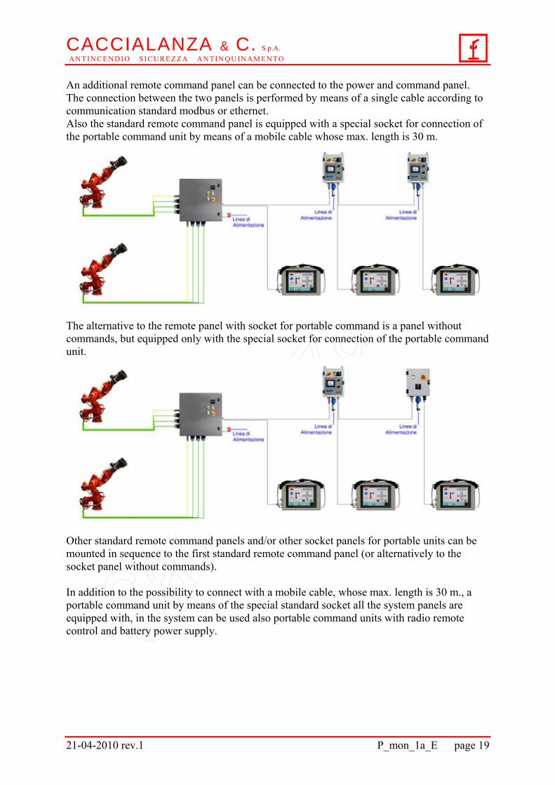
An additional remote command panel can be connected to the power and command panel. The connection between the two panels is performed by means of a single cable according to communication standard modbus or ethernet. Also the standard remote command panel is equipped with a special socket for connection of the portable command unit by means of a mobile cable whose max. length is 30 m.
The alternative to the remote panel with socket for portable command is a panel without commands, but equipped only with the special socket for connection of the portable command unit.
Other standard remote command panels and/or other socket panels for portable units can be mounted in sequence to the first standard remote command panel (or alternatively to the socket panel without commands). In addition to the possibility to connect with a mobile cable, whose max. length is 30 m., a portable command unit by means of the special standard socket all the system panels are equipped with, in the system can be used also portable command units with radio remote control and battery power supply.
CACCIALANZA & C. S.p.A. A N T I N C E N D I O S I C U R E Z Z A A N T I N Q U I N A M E N T O
21-04-2010 rev.1 P_mon_1a_E page 20
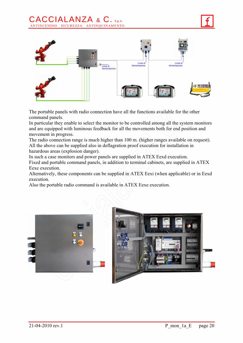
The portable panels with radio connection have all the functions available for the other command panels. In particular they enable to select the monitor to be controlled among all the system monitors and are equipped with luminous feedback for all the movements both for end position and movement in progress. The radio connection range is much higher than 100 m. (higher ranges available on request). All the above can be supplied also in deflagration proof execution for installation in hazardous areas (explosion danger). In such a case monitors and power panels are supplied in ATEX Eexd execution. Fixed and portable command panels, in addition to terminal cabinets, are supplied in ATEX Eexe execution. Alternatively, these components can be supplied in ATEX Eexi (when applicable) or in Eexd execution. Also the portable radio command is available in ATEX Eexe execution.
CACCIALANZA & C. S.p.A. A N T I N C E N D I O S I C U R E Z Z A A N T I N Q U I N A M E N T O
21-04-2010 rev.1 P_mon_1a_E page 21
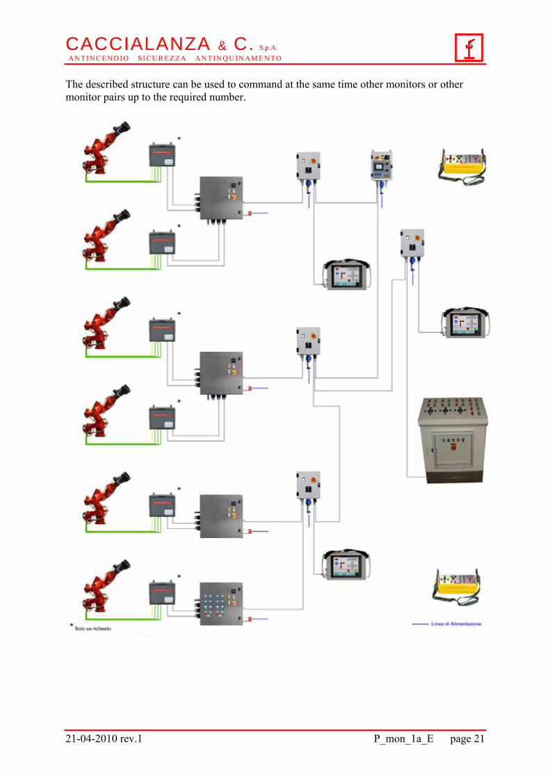
The described structure can be used to command at the same time other monitors or other monitor pairs up to the required number.
CACCIALANZA & C. S.p.A. A N T I N C E N D I O S I C U R E Z Z A A N T I N Q U I N A M E N T O
21-04-2010 rev.1 P_mon_1a_E page 22
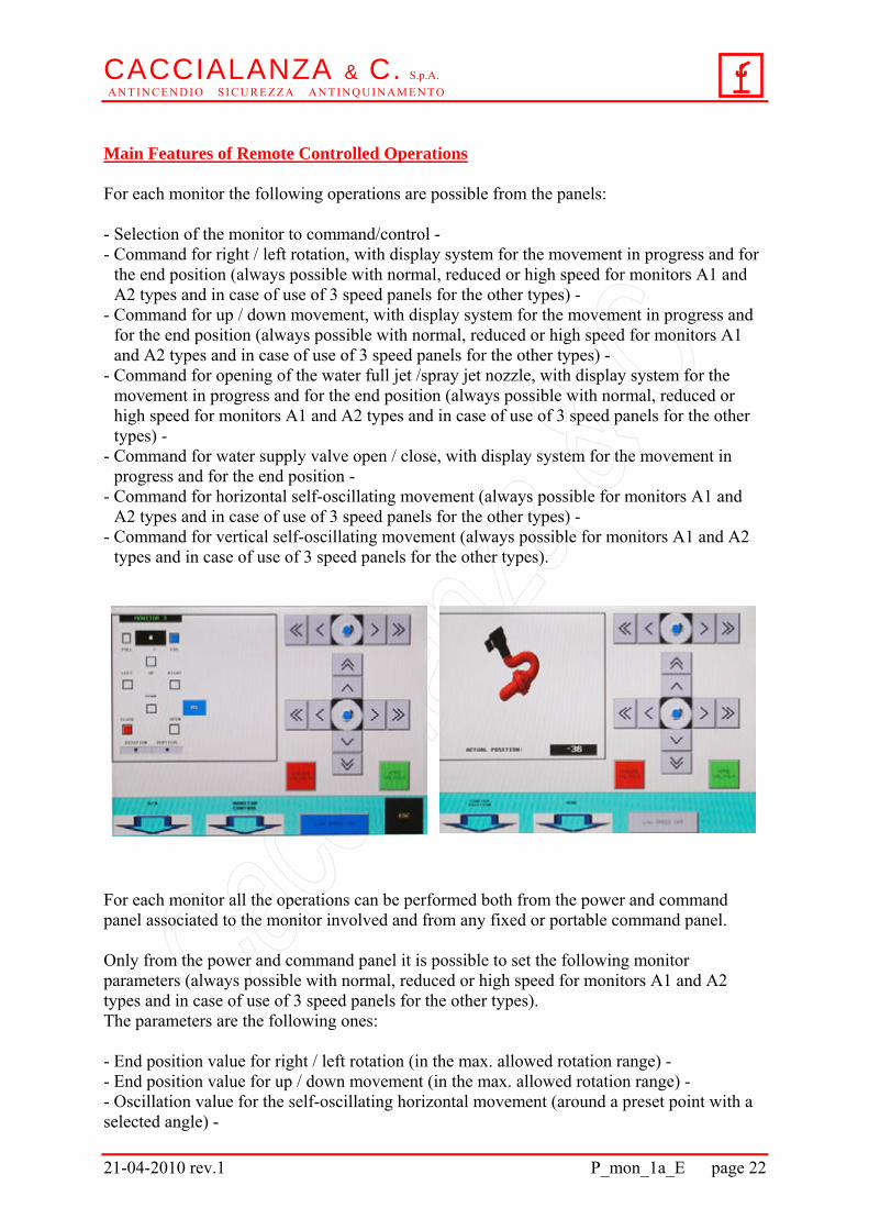
Main Features of Remote Controlled Operations For each monitor the following operations are possible from the panels: - Selection of the monitor to command/control - - Command for right / left rotation, with display system for the movement in progress and for
the end position (always possible with normal, reduced or high speed for monitors A1 and A2 types and in case of use of 3 speed panels for the other types) -
- Command for up / down movement, with display system for the movement in progress and for the end position (always possible with normal, reduced or high speed for monitors A1 and A2 types and in case of use of 3 speed panels for the other types) -
- Command for opening of the water full jet /spray jet nozzle, with display system for the movement in progress and for the end position (always possible with normal, reduced or high speed for monitors A1 and A2 types and in case of use of 3 speed panels for the other types) -
- Command for water supply valve open / close, with display system for the movement in progress and for the end position -
- Command for horizontal self-oscillating movement (always possible for monitors A1 and A2 types and in case of use of 3 speed panels for the other types) -
- Command for vertical self-oscillating movement (always possible for monitors A1 and A2 types and in case of use of 3 speed panels for the other types).
For each monitor all the operations can be performed both from the power and command panel associated to the monitor involved and from any fixed or portable command panel. Only from the power and command panel it is possible to set the following monitor parameters (always possible with normal, reduced or high speed for monitors A1 and A2 types and in case of use of 3 speed panels for the other types). The parameters are the following ones: - End position value for right / left rotation (in the max. allowed rotation range) - - End position value for up / down movement (in the max. allowed rotation range) - - Oscillation value for the self-oscillating horizontal movement (around a preset point with a selected angle) -
CACCIALANZA & C. S.p.A. A N T I N C E N D I O S I C U R E Z Z A A N T I N Q U I N A M E N T O
21-04-2010 rev.1 P_mon_1a_E page 23
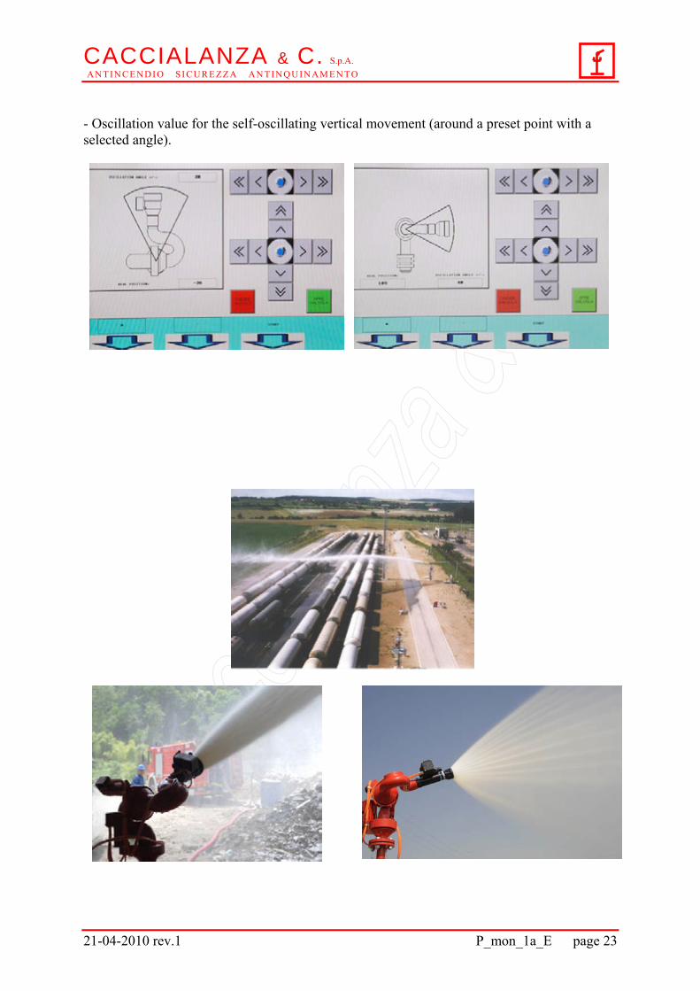
- Oscillation value for the self-oscillating vertical movement (around a preset point with a selected angle).

CACCIALANZA & C. S.p.A. A N T I N C E N D I O S I C U R E Z Z A A N T I N Q U I N A M E N T O
21-04-2010 rev.1 P_mon_1a_E page 24
A WORLDWIDE REFERENCE FOR FIRE EXTINGUISHING AND SECURITY SYSTEMS
IN HEAVY RISK INDUSTRIAL PLANTS Products → Fire Fighting Monitors → Foam Systems → Mobile Foam Components → Mobile Foam Units → Fire Hydrants → Water Spray Nozzles → Dry Powder Units → Powder and Twin Agent Monitors → Systems for Tunnel Protection → Fire Extinguishing Systems for Mobile Units and Vehicles → Water Wall Mitigation Systems → Protection Systems for Large Sites → Electronic Fire Detection and Security Systems → Access Control Systems → Multifunctional Foam Control Systems
Caccialanza & C. reserve the right to change at any time, without prior notice, any specification or feature of the system in order to continuously improve the product.
S. p. A.
I 20090 SEGRATE ( MILANO) VIA PACINOTTI 10 TEL. (+39 ) 02 216918.1 FAX (+39 ) 02 2133861 E-MAIL: [email protected] INTERNET: http://www.caccialanza.it