C M Y CM MY CY CMY K - Pogliano · Energia specifica passante di breve durata riferita a 0,1s -...
12
POGLIANOBUSBAR MB MINIBLINDO ®
Transcript of C M Y CM MY CY CMY K - Pogliano · Energia specifica passante di breve durata riferita a 0,1s -...

C M Y CM MY CY CMY K
POGLIANO BUSBAR s.r.l.
10095 Grugliasco (TO)Corso Allamano, 43Tel. 011 4016611Fax 011 4016652www.blindosbarra.com
Direzione Commerciale ItaliaUfficio di BresciaBorgo Pietro Wührer, 8925125 BresciaTel. 030 2793724Fax 030 2490244
POGLIANOBUSBAR
MB
-09
- ed
. 09/
2009
- c
od. D
0998
2952
6
MBMINIBLINDO®


INDICE GENERALEINDEX
MINIBLINDO® POGLIANOBUSBAR
1
Schema di assemblaggio Assembly layout 2Caratteristiche del sistema System features 3
Elementi rettilinei Straight sections 4Angoli diedri Edgewise elbows 4Angoli piani Flatwise elbow 5
Alimentazioni Feed-in boxes 5Derivazioni Tap-off plugs 6
Staffe di sospensione Hangers 7Portastaffe Brackets 7
Copertura estremità End cover 7
Dati tecnici Technical data 8
CERTIFICAZIONI:La linea MB dispone di certificazioni da parte di laboratori internazional-mente riconosciuti
I prodotti riportati sul presente catalogo possonoessere modificati senza preavviso dallaPOGLIANO BUSBAR srl
The products shown in thiscatalogue may be modifiedwithout warning by POGLIANO BUSBAR s.r.l.
CERTIFICATES:MB system is certified byinternationally accreditedlaboratories
Progetto MB:Layout 1 15-09-2009 11:22 Pagina 1

SCHEMA DI ASSEMBLAGGIO DI UN SISTEMA MINIBLINDOMB SYSTEM LAYOUT
MINIBLINDO® POGLIANOBUSBAR
2
Elemento rettilineoStraight section
Angolo pianoFlatwise elbow
Spina di derivazioneTap-off plug
Angolo pianoFlatwise elbow
AlimentazioneEnd feed-in box
Spina di derivazioneTap-off plug
AlimentazioneEnd feed-in box
Elemento rettilineoStraight section
Angolo diedroEdgewise elbow
Progetto MB:Layout 1 15-09-2009 11:23 Pagina 2

CARATTERISTICHE DEL SISTEMA MINIBLINDO®
MINIBLINDO® SYSTEM FEATURES
MINIBLINDO® POGLIANOBUSBAR
3
Linea MB – Miniblindo. Portate da 63 A 100 A 160 A3P+N+PE IP 55 conduttori in Alluminio. Versioni disponibili a 5 conduttori - 3P+2N+PE (involucro)3P+N+FE (functional heart) +PE (involucro).I codici identificativi della versione a 5 conduttori + PE si ottengonosostituendo la terza cifra rispettivamente con:- il numero 6 (versione 3P+2N+PE involucro).- il numero 7 (versione 3P+N+FE+PE conduttore dedicato).Le restanti numerazioni restano invariate.
Conforme alle norme:EN 60439-1 e 2 - EN 60529 – EN 60332-3
La linea MB è idonea al montaggio in ambiente industriale, terzia-rio e commerciale.Le dimensioni contenute e la sua conformazione permettono l’in-stallazione in orizzontale ed in verticale con cambi di direzione inmaniera molto rapida e semplice ; nel caso di installazioni in con-trosoffitti o pavimenti flottanti, apposite staffe garantiscono il cor-retto posizionamento e l’installazione a regola d’arte.Il sistema di congiunzione e gli accessori a corredo della linea MBconferiscono alla linea facilità e velocità di installazione riducendoi costi di manodopera al minimo.
Alimentazioni:Realizzate in materiale isolante con predisposizione all’imbullona-tura delle barre conduttrici con cavi di alimentazione,coperchiolucchettabile con dispositivo antichiusura accidentale, possibilità diaccogliere cavi fino a 50 mmq in rame e relativi pressacavo IP 55
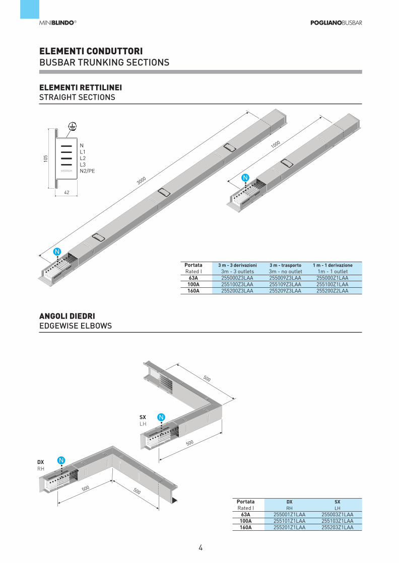
Elementi rettilineiDisponibili in versione da trasporto e distribuzione con lunghezzastandard di 3 m e 1, 5 m; su richiesta sono realizzabili con lunghezzecomprese tra 500 mm e 2999 mm; congiunzione elettrica e mecca-nica mediante sovrapposizione, finestrelle di derivazione applicate daun solo lato ad apertura e richiusura automatica e polarizzazione an-tisbaglio.L’involucro esterno è realizzato in acciaio zincato a caldo, elevataresistenza meccanica alla torsione e flessione ,su richiesta si pos-sono realizzare in acciaio verniciato (RAL) , in alluminio ed in acciaioinox AISI 306.Finestrelle di derivazione n° 3 per elemento disponibili ad inte-rasse di 1000 mm, su richiesta si possono fornire finestrelle diderivazione ad interasse variabile fino ad un massimo di n° 8per elemento l= 3 m.Isolatori supporto barre conduttrici realizzati in materiale autoe-stinguente V1.
Copertura di estremitàRealizzata in acciaio zincato in versioni destra e sinistra in funzionedell’andamento della linea, applicabile sull’estremità di qualsiasielemento conduttore mediante viti M4.
Elementi ad angolo :Realizzati per permettere curve anche diverse da 90 gradi senecessario e di dimensioni da 300 a 500 mm.
Spine di derivazione:realizzate completamente in materiale isolante , portate da 16,32,63A , disponibili in versione vuota con piastra base e guida DIN, por-tafusibili modulari e portafusibili CH 22x58.Nel caso di richiesta si possono fornire con interruttori magneto-termici/differenziali precablati.Montaggio obbligato polarizzato antisbaglio.Le spine di derivazione sono state appositamente progettate per al-lestimenti veloci e manovrabilità in totale sicurezza.Le spine si possono inserire con linea in tensione
Complementi alla linea:Sono stati realizzati una serie di staffe e portastaffe che permettonoqualsiasi tipo di installazione in maniera rapida e sicura .
MB system. Rated currents: 63 A, 100 A, 160 A, TPN+PE IP55.Aluminium conductors. A 5P+Pe version is available on request.
It complies with EN 60439-1 and 2 - EN 60529 - EN 60332-3
MB system is fit for installation in industrial or civil environments.Its compact size and design allow for installation in vertical or ho-rizontal position, with easy changes of direction. In case of in-stallation above false ceilings or under raised floors, appropriatehangers provide for the correct positioning and installation. Thejointing system and accessories make installation easy and cutlabor costs to a minimum.
Feed-in:Made of insulating material, they're set for the bolting of the bu-sbars to the feed-in cables. The cover can be locked and is pro-vided with a device that prevents accidental closing. Set forcopper cables up to 50 square millimeters and IP55 cable clamps.
Straight lengths:Available in feeder and plug-in versions. Standard lengths: 3 mand 1.5 m; on request they can be produced in any length between500 and 3000 mm. Electrical and mechanical jointing by overlap.Tap-off outlets on one side only and with automatic shutter andanti phase-reversal device. The housing is made of (hot-galvanizing) zinc-plated steel. It hasexcellent mechanical withstand ability (against bending and twi-sting). On request it may be produced in painted steel, in alumi-nium or in AISI 306 stainless steel.Three tap-off outlets per 3m element, at a distance of 1 meterfrom each other. On request this distance may be varied, with amaximum of 8 tap-off outlets per 3m element. V1 Self-estinguishing busbar support insulators.
End cover (right-hand or left-hand):Made of zinc-plated steel. It may be fastened to the end of anyelement by means of M4 screws.
Elbows:Elbows (different from 90 degrees on request) and of sizes varyingfrom 300 to 500, edgewise or flatwise.
Tap-off plugs:made entirely of insulating material, for rated currents of 16, 32and 63 A. Empty with DIN railing or with modular fuseholders orwith CH 22x58 fuseholders. On request they may be supplied withpre-cabled MCCB's. Anti phase-reversal device. Tap-off plugs are designed for quick and safe installation and ope-ration.
Accessories:a set of hangers and brackets provide for any type of installationquickly and safely.
Progetto MB:Layout 1 15-09-2009 11:23 Pagina 3
1000
3000
ELEMENTI CONDUTTORIBUSBAR TRUNKING SECTIONS
MINIBLINDO® POGLIANOBUSBAR
4
ELEMENTI RETTILINEISTRAIGHT SECTIONS
Portata 3 m - 3 derivazioni 3 m - trasporto 1 m - 1 derivazioneRated I 3m - 3 outlets 3m - no outlet 1m - 1 outlet
63A 255000Z3LAA 255009Z3LAA 255000Z1LAA100A 255100Z3LAA 255109Z3LAA 255100Z1LAA160A 255200Z3LAA 255209Z3LAA 255200Z2LAA
Portata DX SXRated I RH LH
63A 255001Z1LAA 255003Z1LAA100A 255101Z1LAA 255103Z1LAA160A 255201Z1LAA 255203Z1LAA
ANGOLI DIEDRIEDGEWISE ELBOWS
500
500
500
500
DXRH
SXLH
105
42
NL1L2L3N2/PE
N
N
N
N
Progetto MB:Layout 1 15-09-2009 11:23 Pagina 4

ELEMENTI CONDUTTORIBUSBAR TRUNKING SECTIONS
MINIBLINDO® POGLIANOBUSBAR
5
ANGOLI PIANIFLATWISE ELBOWS
Portata DX SXRated I RH LH160A 255251Z0LAA 255252Z0LAA
ALIMENTAZIONE DI TESTATAFEED-IN BOX
DXRH
SXLH
SXLH
500
500
500
500
DXRH
Portata DX SXRated I RH LH
63A 255002Z1LAA 255004Z1LAA100A 255102Z1LAA 255104Z1LAA160A 255202Z1LAA 255204Z1LAA
N
N
150
240
150
240
N
N
Progetto MB:Layout 1 15-09-2009 11:23 Pagina 5
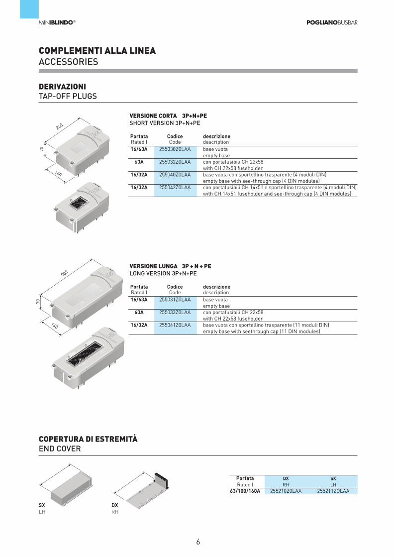
COMPLEMENTI ALLA LINEAACCESSORIES
MINIBLINDO® POGLIANOBUSBAR
6
DERIVAZIONITAP-OFF PLUGS
COPERTURA DI ESTREMITÀEND COVER
240
70
000
70
DXRH
SXLH
Portata DX SXRated I RH LH
63/100/160A 255210Z0LAA 255211ZOLAA
Portata Codice descrizioneRated I Code description16/63A 255030Z0LAA base vuota
empty base63A 255032Z0LAA con portafusibili CH 22x58
with CH 22x58 fuseholder16/32A 255040Z0LAA base vuota con sportellino trasparente (4 moduli DIN)
empty base with see-through cap (4 DIN modules)16/32A 255042Z0LAA con portafusibili CH 14x51 e sportellino trasparente (4 moduli DIN)
with CH 14x51 fuseholder and see-through cap (4 DIN modules)
VERSIONE CORTA 3P+N+PESHORT VERSION 3P+N+PE
Portata Codice descrizioneRated I Code description16/63A 255031Z0LAA base vuota
empty base63A 255033Z0LAA con portafusibili CH 22x58
with CH 22x58 fuseholder16/32A 255041Z0LAA base vuota con sportellino trasparente (11 moduli DIN)
empty base with seethrough cap (11 DIN modules)
VERSIONE LUNGA 3P + N + PELONG VERSION 3P+N+PE
140
140
Progetto MB:Layout 1 15-09-2009 11:23 Pagina 6
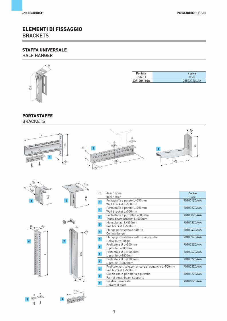
ELEMENTI DI FISSAGGIOBRACKETS
MINIBLINDO® POGLIANOBUSBAR
7
STAFFA UNIVERSALEHALF HANGER
PORTASTAFFEBRACKETS
Portata CodiceRated I Code
63/100/160A 255020Z0LAA
120
3015
0
145
L 500
200
50 195
40
130
130
50
41
30
50
L
80
30
21
200
500 5001
2 3
4 5
6
8 9
7
Rif. descrizione Codicedescription CodePortastaffa a parete L=550mm 901001Z0AAAWall bracket L=550mmPortastaffa a parete L=750mm 901002Z0AAAWall bracket L=550mmPortastaffa a putrella L=500mm 901008Z0AAATruss-beam bracket L=500mmMensola fast L=500mm 901013Z0AAAfast bracket L=500mmFlange portastaffa a soffitto 901004Z0AAACeiling flangeFlange portastaffa a soffitto rinforzata 901009Z0AAAHeavy duty flangeProfilato a U L=500mm 901005Z0AAAU profile L=500mmProfilato a U L=1000mm 901006Z0AAAU profile L=1000mmProfilato a U L=2000mm 901007Z0AAAU profile L=2000mmProfilato verticale con ancore di aggancio L=500mm 901003Z0AAAfast bracket L=500mmCoppia rostri per staffa a putrella 901012Z0AAAPair of truss-beam supportsPiastra universale 901010Z0AAAUniversal plate
1
1
2
3
4
5
6
6
6
7
8
9
Progetto MB:Layout 1 15-09-2009 11:23 Pagina 7

DATI TECNICITECHNICAL DATA
MINIBLINDO® POGLIANOBUSBAR
8
Grado di protezione IPProtection Degree IPIntensità nominale In (A)Rated CurrentSezione conduttori di fase Sf (mmq)Phase cross sectionSezione conduttori di neutro Sn (mmq)Neutral cross sectionSezione conduttore di protezione (mmq Fe) Spe (mmq)Protective conductor cross sectionSezione conduttore di protezione (mmq Cu) Spe (mmq)Protective conductor cross sectionTensione nominale di isolamento Ui (V)Insulation rated voltageCorrente nominale ammissibile di breve durata (KA) (0,1s) trifase ICW (KA)Short-circuit rated current (short-time) 3-phaseCorrente nominale ammissibile di breve durata (KA) (0,1s) fase-N ICW (KA) Short-circuit rated current (short-time) phase-nCorrente nominale ammissibile di breve durata (KA) (0,1s) fase-PE ICW (KA)Short-circuit rated current (short-time) phase-peCorrente nominale di picco ammissibile (KA) per c.c. trifase Ipk (KA)Short-circuit rated current (peak) 3-phaseCorrente nominale di picco ammissibile (KA) per c.c. fase-N Ipk (KA)Short-circuit rated current (peak) phase-nCorrente nominale di picco ammissibile (KA) per c.c. fase-PE Ipk (KA)Short-circuit rated current (peak) phase-peEnergia specifica passante di breve durata riferita a 0,1s - trifase (A2s)* 106
Specific energy (short-time)Energia specifica passante di breve durata riferita a 0,1s - Neutro - PE (A2s)* 106
Specific energy (short-time)Energia specifica passante di breve durata riferita a 0,1s - fase - PE (A2s)* 106
Specific energy (short-time)Resistenza a Rt (mΩ/100m) RtPhase resistanceResistenza a 20° C (mΩ/100m) R20Phase resistanceReattanza (mΩ/100m) XfPhase reactanceImpedenza a 20° C (mΩ/100m) Z20Phase impedanceImpedenza a equilibrio termico (mΩ/100m) ZtPhase impedanceResistenza spira di guasto (mΩ/100m) fase-N R0-NFault loop resistanceReattanza spira di guasto (mΩ/100m) fase-N X0-NFault loop reactanceImpedenza spira di guasto (mΩ/100m) fase-N Z0-NFault loop impedanceResistenza spira di guasto (mΩ/100m) R0-PEFault loop resistanceReattanza spira di guasto (mΩ/100m) X0-PEFault loop reactanceImpedenza spira di guasto (mΩ/100m) Z0-PEFault loop impedancePerdite Joule a In 3RI2 P(W/m)Joule losses In 3RI2
Massa (Kg/m)Mass
160A100A
55
63
45
45
311
39
750
3
3
3
10
10
10
0,9
0,9
0,9
0,745
0,710
0,237
0,748
0,782
1,49
0,237
1,31
1,155
0,337
1,21
8,870715
3
55
100
54
54
311
39
750
5
5
5
10
10
10
2,5
2,5
2,5
0,649
0,590
0,210
0,626
0,682
1,30
0,21
1,31
1,059
0,31
1,1
19,47
3,1
55
160
60
60
311
39
750
6,5
6,5
5
10
10
10
4,25
4,25
2,5
0,636
0,530
0,200
0,566
0,667
1,27
0,2
1,31
1,046
0,3
1,09
48,8448
3,1
63A
Progetto MB:Layout 1 15-09-2009 11:23 Pagina 8

C M Y CM MY CY CMY K
POGLIANO BUSBAR s.r.l.
10095 Grugliasco (TO)Corso Allamano, 43Tel. 011 4016611Fax 011 4016652www.blindosbarra.com
Direzione Commerciale ItaliaUfficio di BresciaBorgo Pietro Wührer, 8925125 BresciaTel. 030 2793724Fax 030 2490244
POGLIANOBUSBAR
MB
-09
- ed
. 09/
2009
- c
od. D
0998
2952
6
MBMINIBLINDO®